Embed Size (px)
Citation preview

© Baxi Heating UK Ltd 2011
G U I D A N C E N OT E S
Solar CollectorsOn-Roof Installation (First Fix)
Please leave these instructionswith the User
© Baxi Heating UK Ltd 2012


Symbols and tools
Health and safety
Kit Contents and Components
Snow and Wind Load
Notes
Installation
Fixation position
Weight and dimensions
Legislation, recommendations and maintenance
1.0
2.0
3.0
4.0
5.0
6.0
7.0
8.0
9.0
Contents
4
9
21
6
12
23
5
10
22

Tile cutter
4
1.0
Meter tape
Hammer
Spanner Tight (13mm/32mm)
Symbols
Caution
Page Reference Number
Extention of the collector
1 Collector
Weight
Measure
Information
Material purchased separately
2 Collectors
Maximum pressure
Supplied separately
bar01 0
+
Tools
Drill / Diver

5
2.0Health and safety
Use safety helmet. Danger of lightning in stormy weather
Beware of tripping
Heavy load
Beware of slippery surfaces
Beware of high temperatures
Handle collector by grasping the profile
Use safety shoes.
Use safety harness for protection against falling.
Use safety gloves.
Use safety goggles.
Include the collector in the lightning protec-tion device of the building.
kg

2 2 2
- - -
4 4 4
- - -
2 2 2
4 4 4
4 4 4
4 4 4
4 4 4
8 8 8
9 9 9
8 8 8
4 4 4
1 1 1
6
A
B
C
D
E
F
G
H
J
K
L
M
N
O
4 4 4 2 2 2
2 2 2 2 2 2
4 4 4 - - -
2 2 2 2 2 2
4 4 4 2 2 2
6 6 8 2 2 4
6 6 8 2 2 4
6 6 8 2 2 4
4 4 4 - - -
12 12 14 4 4 6
12 12 16 4 4 4
12 12 16 4 4 8
6 6 8 2 2 4
1 1 1 - - -
3.0
SO
L 20
0 P
SO
L 20
0 P
SO
L 20
0 P
SO
L 25
0 P
SO
L 25
0 P
SO
L 25
0 P
SO
L 20
0 L
SO
L 20
0 L
SO
L 20
0 L
Kit Contents and Components
+

7
A
C
B
K
DJ
E
M
L
G
H
F
N
3.0
A- Rail B- Joining PlateC- End ClampD- Join Stud PlateE- Support BracketF- Lower BracketG- Under Tile BeamH- Upper BracketJ- T-Bolts M8x30K- M8 NutsL- M8 WashersM- 8x60mm Wood screwsN- Captive 8mm washerO- Intructions

8
3.1 Hydraulic kit contents and components
S3
S12
S6
S11
S8 S9
S4
S2S1
S5
S10
S7
S1- End CapS2- Joining PieceS3- ElbowS4- Manual Air Vent (Optional part)S5- Tee Piece (Optional part)S6- ClipS7- Plug for manual Air Vent (Optional part)S8- Auto Air Vent (Optional part)S9- 2m Pipe KitS10- Straight Connector with FittingsS11- Temperature SensorS12- Sensor Elbow

9
y
x
z
kg
4.0Weight and dimensions
35 10 1147 1753 87
48 10 1147 2187 87
36 10 1753 1147 87
SOL 200 P
SOL 250 P
SOL 200 L
(bar)(kg) (mm) (mm) (mm)x y zbar01 0

Fixation position
SOL 200 P 1187 1250-1550
SOL 250 P 1187 1750-1950
a(mm) (mm)b
10
5.0
300
300
300
125
300 300
300
<_ <_
<_
<_ <_
<_
+ . . . +
a
a
a
a300 300
300 300
b
b
<_ <_
<_ <_
125
a a300
300
b
<_
<_
125

SOL 200 P 1187 1250-1550
SOL 250 P 1187 1750-1950
SOL 200 L 1793 700-900
a(mm) (mm)b
11
5.0
+ . . . +
300
300
125
300
300
<_
<_
<_
<_
125
300
300
300
300
<_
<_
<_
<_
300 300
300 300
300
300
< <
< <
<_ _
_ _
_
<_
a a a
a
a
a
300
300
<_
<_
125
300 300
300 300
300
300
< <
< <
<_ _
_ _
_
<_
b
b
b
300
300
<_
<_

12
6.0
1
2
3
x2
a
10-11
Installation
The illustrations in this manual may differ from the equipment supplied.
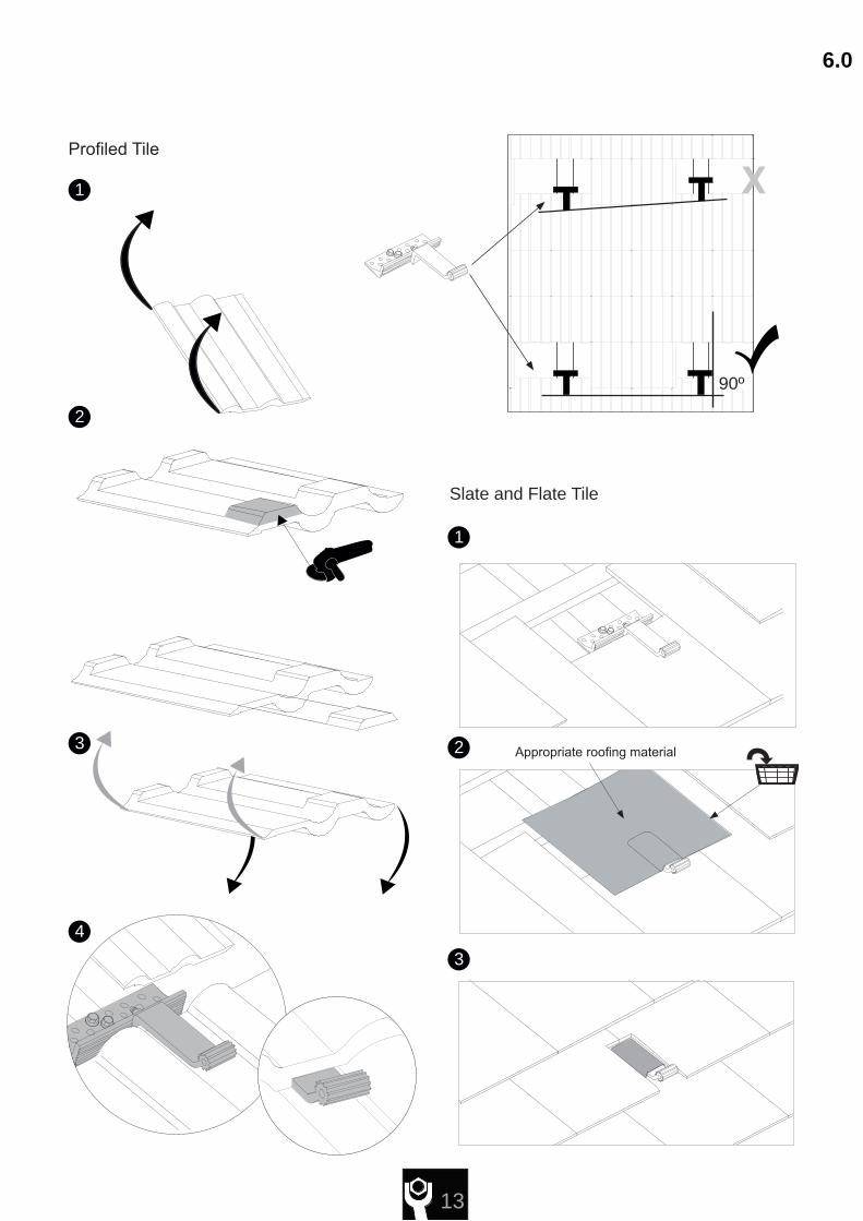
13
1
2
3
4
6.0
90º
1
2
3
Profiled Tile
Slate and Flate Tile
Appropriate roofing material

14
6.0
1
1
2
a (mm) (mm) (mm)b c
Z1 50 80 105Z2 58 87 112
<_<_ <_
Z1
Z2
a
b
c
Installation

15
6.0
!
1
2 3
<_
<_
<300mm
<300mm

16
300mm
300mm
<_
<_
6.0
6.0
Installation

200mm<_
17
6.0
21
!
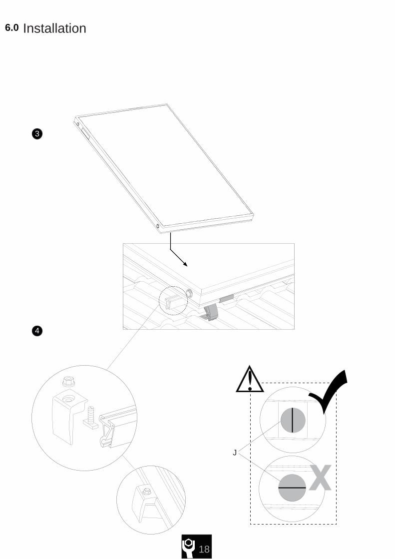
18
3
4
6.0 Installation
J

40mm
19
2
31
6.0

20
4
6.0 Installation

21
EN1991
7.0Snow and Wind Load
Design limit snow load on the ground = Sol 200 P/ Sol 200 L = 2.3kN/m² Sol 250 P = 1.9kN/m²
NOTE: This limit will be reduced for installations where abutments create additional risks of drifting or falling snow. In high snow load areas (greater than 1kN/m²) it is recommended that a snow fence is fitted at maximum distance of 0.5m above the collector.
The maximum wind load to be borne by the mounting structure depends on the height and geographical area of the site among other factors This structure must be installed in accordance with the provisions of the EN1991 standard. Consult your official dealer if in doubt.

22
8.0 Legislation, recommendations and maintenance
LEGISLATION
Please note the following instructions regarding laws, regulations and technical rules.When setting up solar energy installations, the laws and regulations at local, state, European and international level that apply to the country in question must be obser-ved. Generally acknowledged technical regulations apply; these are usually formulated in the form of standards, guidelines, provisions, regulations and technical rules laid down by local and national bodies, energy supply companies, trade organisations and technical committees in the relevant fields. The installation of solar units may require improved rain resistance with regard to roof, wall and sealing technology and this must be taken into account accordingly. To meet regulations for the prevention of accidents, it may be necessary to use safety equipment (straps, scaffolding, supports, etc.). Such safety equipment is not supplied. Installation must only be carried out by technically qualified and authorised personnel with a recognised qualification (verified by a state or national body) in the relevant technical area.
RECOMMENDATIONS- Use a safety harness when working at height.- The structure of the roof must be assessed for its suitability prior to commencing work.- Consult a Structural Engineer if you are unsure of the collector’s siting.- Loading due to snow may exceed the capability of the property’s structure.- Wind loads may cause excess forces on the structure and cause damage.- The Installer is responsible for the suitability of the site and its sub-structure.- An anchor plug and bolt may be used to secure the collector on a suitable roof sur-face.- The collector should be sited to avoid damage from falling debris and vandalism.- All pipe work within this installation must be Earth bonded.- In exposed areas, the collector must be protected against the risk of lightning.- It is recommended that a minimum of 2 people are used to lift this product.- The collector must not be lifted by its pipe connections.- Ensure all hydraulic connections are securely fixed and are free of leaks.- The system must be inspected on completion of the work.- A further inspection is recommended annually.- Avoid installing the collector in shaded areas.- The general recommended torque setting for nuts and bolts is 10Nm.- Large arrays will require specialist piping, pump groups and design.- The collector must not be installed on an uneven roof surface.- Do not apply excessive force when installing the collector.- Hot, exposed surfaces that can be touched must be insulated to protect against injury.- Lubrication is not required for the ‘O’ ring connections.- A separate second array can be installed behind the first if necessary.-The mounting at 90° on a wall must be possible (on the on-roof profile) but only if the panel is covered on his top with a cover which is build by the installer.
MAINTENANCEIt is recommended that the following checks are carried out on an annual basis:1) Check the collector installation for any signs of damage or any build up of debris.2) Check for any corrosion to the collector or the mounting system and repair if ne-cessary.3) Check the tightness of the fasteners. Where fasteners cannot be readily accessed, the overall security of the collector installation may indicate whether problems exist.4) Check the fittings and pipe work for any signs of fluid leakage or damage, includin the condition of the pipe insulation, and repair if necessary. Check inside the building for any evidence of leaks.5) Examine the roof tiles around the collector installation for any damage or deteriora-tion, and repair if necessary.6 )Check for any foliage growth that may cause shading of the collectors.7) Where applicable, check the condition of any ballast used to secure the system.8) In areas where there may be a build up of dirt on the collector, only nonabrasive cleaning materials and methods should be used to clean the collectors and mounting system components.

23
9.0Notes

SP Comp No 720290903c (04/12)
720290903
All descriptions and illustrations provided in this leaflet have been carefullyprepared but we reserve the right to make changes and improvements inour products which may affect the accuracy of the information contained inthis leaflet. All goods are sold subject to our standard Conditions of Salewhich are available on request.
MULTIFITA Trading Division of Baxi Heating UK Ltd (3879156)Brooks House, Coventry Road, Warwick. CV34 4LLTechnical Enquiries 0844 871 1568Website www.bdrthermea.com
e&oe
© Baxi Heating UK Ltd 2012