Embed Size (px)
Citation preview
HAL Id: hal-00733773https://hal.archives-ouvertes.fr/hal-00733773
Submitted on 19 Sep 2012
HAL is a multi-disciplinary open accessarchive for the deposit and dissemination of sci-entific research documents, whether they are pub-lished or not. The documents may come fromteaching and research institutions in France orabroad, or from public or private research centers.
L’archive ouverte pluridisciplinaire HAL, estdestinée au dépôt et à la diffusion de documentsscientifiques de niveau recherche, publiés ou non,émanant des établissements d’enseignement et derecherche français ou étrangers, des laboratoirespublics ou privés.
Guidance of Unmanned Surface Vehicles: Experimentsin Vehicle Following
Marco Bibuli, Massimo Caccia, Lionel Lapierre, Bruzzone Gabriele
To cite this version:Marco Bibuli, Massimo Caccia, Lionel Lapierre, Bruzzone Gabriele. Guidance of Unmanned SurfaceVehicles: Experiments in Vehicle Following. IEEE Robotics and Automation Magazine, Institute ofElectrical and Electronics Engineers, 2012, 19 (3), pp.92-102. �10.1109/MRA.2011.2181784�. �hal-00733773�
Control of UnmannedSurface VehiclesExperiments in Vehicle Following
•By Marco Bibuli, Massimo Caccia, Lionel Lapierre, and Gabriele Bruzzone
Virtual target-based path-following techniquesare extended to execute the task of vehicle fol-lowing in the case of unmanned surface vehicles(USVs). Indeed, vehicle following is reduced to theproblem of tracking a virtual target moving at a
desired range from a master vessel, while separating thespatial and temporal constraints, giving priority to theformer one. The proposed approach is validated experi-mentally in a harbor area with the help of the prototypeUSVs ALANIS and Charlie, developed by Consiglio Nazio-nale delle Ricerche-Istituto di Studi sui Sistemi Intelligentiper l’Automazione (CNR-ISSIA) <AU: Please checkwhether the expanded form of “CNR-ISSIA” Is correct.>.
The 21st century’s scenarios of marine operations,regarding environmental monitoring, border surveillance,warfare, and defense applications, foresee the cooperationof networked heterogeneous manned/unmanned air,ground, and marine platforms. Examples are given by theautonomous ocean sampling network, integrating roboticvehicle and ocean models to increase the capacity ofobserving and predicting the ocean behavior and theBarents 2020 vision, optimizing marine resources; thanksto historical and real-time information collected by a largenetwork of cooperating vehicles.
In this framework, USVs, given their position at theair–sea interface, can play a key role both in relayingradio-frequency transmissions in air and acoustic trans-missions undersea, as proposed, for instance, in the Euro-pean Commission (EC)-funded <AU: Please check
1070-9932/11/$26.00ª2011 IEEE DECEMBER 2011 • IEEE ROBOTICS & AUTOMATIONMAGAZINE • 1
Digital Object Identifier 10.1109/MRA.2011.942995
Date of publication:
IEEE
PROOF
whether the spell out form of EC is correct.> ASIMOVproject [1], and monitoring ocean and atmospheredynamics as well as surface and underwater intrusions.As a consequence of their networking capabilities, USVsare naturally seen as a part of flotillas of heterogeneousvehicles executing large-scale surveys and supportingrapid environmental assessment (REA). The result is thatan increasing number of prototype vehicles have beendeveloped for science, bathymetric mapping, defense, andgeneral robotics research. For an overview of the devel-oped prototype vessels and basic design and researchtrends and issues, the reader can refer to [2].
In this context, the research presented in the followingdeals with aspects related to cooperative motion control ofunmanned marine vehicles (UMVs), focusing on the theo-retical and experimental study of the problem of a slaveUSV following a master vessel at a predefined range. Thissimple formation configuration, with its natural extensionto a fleet of slaves vehicles following a master vessel, is thebase for a number of different applications. An example isgiven by the execution of morphobathymetric surveys invery shallow water, such as coastal lagoons, combining theuse of vertical incidence echosounders and subbottom chirpdevices [3]. In this case, a flotilla of USVs can constitute aforce multiplier in executing multiple surveys with the samesensor, installed aboard the master and slave vessels, respec-tively, or using different sensors in the same place at thesame time with respect to the spatiotemporal resolution ofthe phenomena under investigation, as in the case of acous-tic devices that cannot work when mounted below the samehull. A team of heterogeneous USVs able to tackle this prob-lem is currently under development at the NationalResearch Council of Italy. Other interesting operational sce-narios include surveys, i.e., periodic bathymetries for evalu-ating the distribution of sediments and classifying theirquality, of harbor areas for driving dredging, coastal land-slides and sand distribution for beach maintenance, andartificial lakes, including dam inspection.
The main contribution of this article relies in the exper-imental validation of guidance techniques, i.e., virtual tar-get-based path following and their extension to handlemultivehicle cooperation as well as in identifying the majorsources of performance limitations. Successful experimen-tal demonstrations, contributing to bridge the gap betweentheory and practice, push the development of operationalmarine robots for marine monitoring, surveillance, explo-ration, and exploitation.
In particular, experiments have been carried out in aharbor area using the Charlie USV [4] as a slave vehicleand the dual-mode ALANIS vessel [5], in this case pilotedby a human operator, as a master vehicle. As discussed inthe following, the proposed guidance law privileges thespatial constraint of driving the slave vehicle over the refer-ence path with respect to the temporal requirement ofmaintaining a desired range from the master vessel. Thetarget path, defined by the motion of the master vessel, is
followed by adopting a conventional nonlinear path-following algorithm of the type discussed in [6].
Problem Definition and State-of-the-ArtIn the literature, motion control scenarios of USVs areusually classified into three main categories (pointstabilization, trajectory tracking, and path following),along with the concept of path maneuvering (see, forinstance, [7]).l Point stabilization: The goal is to stabilize the vehicle
zeroing the position and orientation error with respectto a given target point with a desired orientation (in theabsence of currents). The goal cannot be achieved withsmooth or continuous state-feedback control laws whenthe vehicle has nonholonomic constraints. In the pres-ence of currents, the desired orientation is not specified.
l Trajectory tracking: The vehicle is required to track atime-parameterized reference. For a fully actuated sys-tem, the problem can be solved with advanced nonlinearcontrol laws; in the case of underactuated vehicles, i.e.,the vehicle has less degrees of freedom than state varia-bles to be tracked, the problem is still a very active topicof research.
l Path following: The vehicle is required to converge to andfollow a path without any temporal specification. Theassumption made in this case is that the vehicle’s forwardspeed tracks a desired speed profile, while the controlleracts on the vehicle orientation to drive it to the path. Thistypically allows a smoother convergence to the desiredpath with respect to the trajectory tracking controllers,less likely pushing to saturation the control signals.
l Path maneuvering: The knowledge about the vehicle’smaneuverability constraints enables the design of speedand steering laws that allow for feasible path negotiation.In recent years <AU: Please check whether “last years”
can be changed to “recent years”>, the above-mentionedscenarios have been extended to the case of coordinatedand/or cooperative guidance of multiple vessels, basicallyintroducing the concept of formation, i.e., geometric dis-position of a set of vehicles.
As discussed in [8], a fleet of vessels can be required totrack a set of predefined spatial paths while holding adesired formation pattern and speed (cooperative path fol-lowing) to follow (in space) or track (in space and time) amoving target (cooperative target following and tracking,respectively). It is worth noting that these problems can besolved by converting them into an equivalent virtual tar-get-based path-following problem. In particular, the so-called path-tracking scenario, in which the vehicle isrequired to track a target that moves along a predefinedpath, is the basic component of cooperative target-follow-ing/tracking systems. Indeed, with respect to trajectorytracking, path tracking separates the spatial and temporalconstraints, giving priority to the former one, i.e., the vehi-cle tries to move along the path and then to zero the rangefrom the target, as, for instance, in the case of a virtual
2 • IEEE ROBOTICS & AUTOMATIONMAGAZINE • DECEMBER 2011
IEEE
PROOF
target moving at a desired range from a master vessel(vehicle-following scenario).
In this context, a number of preliminary experimentson multiple vehicle cooperative guidance were performedusing combinations of USVs, autonomous underwatervehicles (AUVs), and manned vessels. Indeed, after firstdemonstrations carried out with autonomous kayaksSCOUT <AU: Please spell out “SCOUT.”> in the UnitedStates to validate COLREGS <AU: Please spell out
“COLREGS”.> -based anticollision for UMVs [9],research focused on vehicle following, cooperative pathfollowing and target tracking, as well as mission coordina-tion of multiple vehicles in the case of poorcommunication.
In particular, the need of collecting bathymetric data inan REA framework is strongly pushing research in vehiclefollowing to support an operating scenario where a mastervessel is followed on its sides by a flotilla of small USVs.The first full-scale experiment in a civilian setting world-wide, involving as USV a retrofitted leisure boat of length8.5 with a maximum speed of 18 knots and as mannedvehicle a research vessel of length 30 with an upper speedof 13 knots, was performed in Trondheimsfjord, Norway,on September 2008 [10]. In the following year, the experi-ment was replicated with a couple of slave vehicles follow-ing the master vessel [11] (a video describing theexperiment can be found at http://www.youtube.com/watch?v=i_NrA5DwIcc ).
Very interesting preliminary demonstrations of cooper-ative control of multiple UMVs, supported by a large theo-retical work, were performed in the framework of the EC-funded project GREX [Instituto Superior Tecnico (IST)-Project No. 035223] about coordination and control ofcooperating heterogeneous unmanned systems in uncer-tain environments. In particular, experiments oriented toevaluate the possibility of coordinating the operations ofmultiple AUVs in the presence of very limited underwateracoustic communications were carried out with theIFREMER’s <AU: Please spell out “IFREMER.”> AUVsAsterx and AUVortex in the Toulon area, France, onNovember 2008 [12]. During these trials, Asterx, the fasterAUV, when measuring an excessive coordination error,sent the coordinates of a target point that the slower AUV,AUVortex, had to reach, while Asterx was circling aroundthe waiting location.
Preliminary experiments, aiming at validating the exe-cution of vehicle primitives, such as path following and tar-get following, were carried out with the DELFIMx ASV<AU: Please spell out “DELFIM” and “ASV.”> followingthe human-piloted boat Aguas Vivas by the researchers ofthe IST of Lisbon in Azores in May 2008 [8].
On November 2009, coordinated path-followingexperiments involving the USVs DELFIM and DELFIMxby the IST of Lisbon, the AUV SEABEE <AU: Please spell
out “SEABEE.”> by Atlas Elektronic, and the AUVortexby IFREMER were carried out in Sesimbra, Portugal [13].
The vehicles that operated on the surface communicatingthrough a radio link had to follow paths composed by asegment of line, followed by an arc, and then finalized by asegment of line, while keeping an in-line formation, i.e.,aligning themselves along a straight line perpendicular tothe paths.
In the meantime, the autonomous kayaks SCOUT wereexploited for evaluating the capacities of autonomouscooperation of AUVs and USVs in executing search tasksat sea, e.g., mine countermeasures [14], as well as foradaptive collection of oceanographic data, e.g., characteri-zation of the sound speed profile with multiple USVs [15].Very interesting experiments on the cooperative maneu-vering of a couple of USVs for capturing a floating objectand shepherding it to a designated position were carriedout by the University of Southern California [16].
Vehicle FollowingThe problem of cooperative path following, where a slavevehicle follows a master maintaining a predefined positionconfiguration, is addressed in this section. In particular,the proposed approach assumes that the slave vehicledoesn’t a priori know the path to be followed: the masterexecutes its motion, i.e., automatically following a path orbeing driven by a human operator and sends basic naviga-tion information to the slave. From this reduced set ofinformation (for instance, master’s position, actual veloc-ity, and orientation), the slave vehicle online reconstructsthe path to be followed. This means that the only con-straints on the master vessel are given by the fact that it hasto be equipped with simple sensors and a communicationsystem to send the navigation data to the slave vehicle.
The goal is to have a slave USV following the path of amaster vessel at a fixed range, measured in terms of curvi-linear abscissa of the desired path or linear distance in aspecific direction in a suitable reference frame (typically,rigidly fixed to the master). Indeed, the problem consists oftracking an online-defined path, giving priority to thespatial constraints with respect to the temporal ones. Thus,since the main objective is that the two vehicles follow thesame path, the proposed approach consists of three steps(executed at each control cycle):l reconstructing the master path on the basis of continu-
ously collected navigation datal guiding the vehicle over the reference path according to
a conventional path-following algorithml adapting the vehicle surge speed according to the error
from the desired distance from the master.It is worth noting that, according to research results
presented in [6], the vehicle-following controller isdesigned at the guidance level generating reference yawrate and surge, that, in the case of the Charlie USV, aretracked by suitable PI <AU: Please spell out PI.> gain-scheduling velocity controllers. In the operative frameworkused for validating the proposed approach, a slave vehicleis in charge of following exactly the shape of the path
DECEMBER 2011 • IEEE ROBOTICS & AUTOMATIONMAGAZINE • 3
IEEE
PROOF
executed by a human-driven master vessel, maintaining adesired position configuration with respect to it. Forinstance, the slave has to follow the master’s path keeping adesired distance from its stern or (path-based) curvilineardistance between the two vehicles. While moving, themaster transmits basic navigation information to the slave,i.e., horizontal position provided by GPS <AU: Pleasespell out GPS.>, when working with surface vessels, oracoustic positioning systems when underwater vehicles areinvolved. This basic information set can be augmented forinstance adding when the master follows a predefinedpath, actual tangent and curvature values. Collecting thedata provided by the master, the slave online generates areference path that is followed using a Lyapunov-basedguidance law improved with the virtual target approach, aspresented in [6] and summarized in the following subsec-tion. To maintain the desired range from the master, theslave’s surge velocity is adapted according to a saturatedproportional integral function of the desired distance, lin-ear or curvilinear, between the two vehicles.
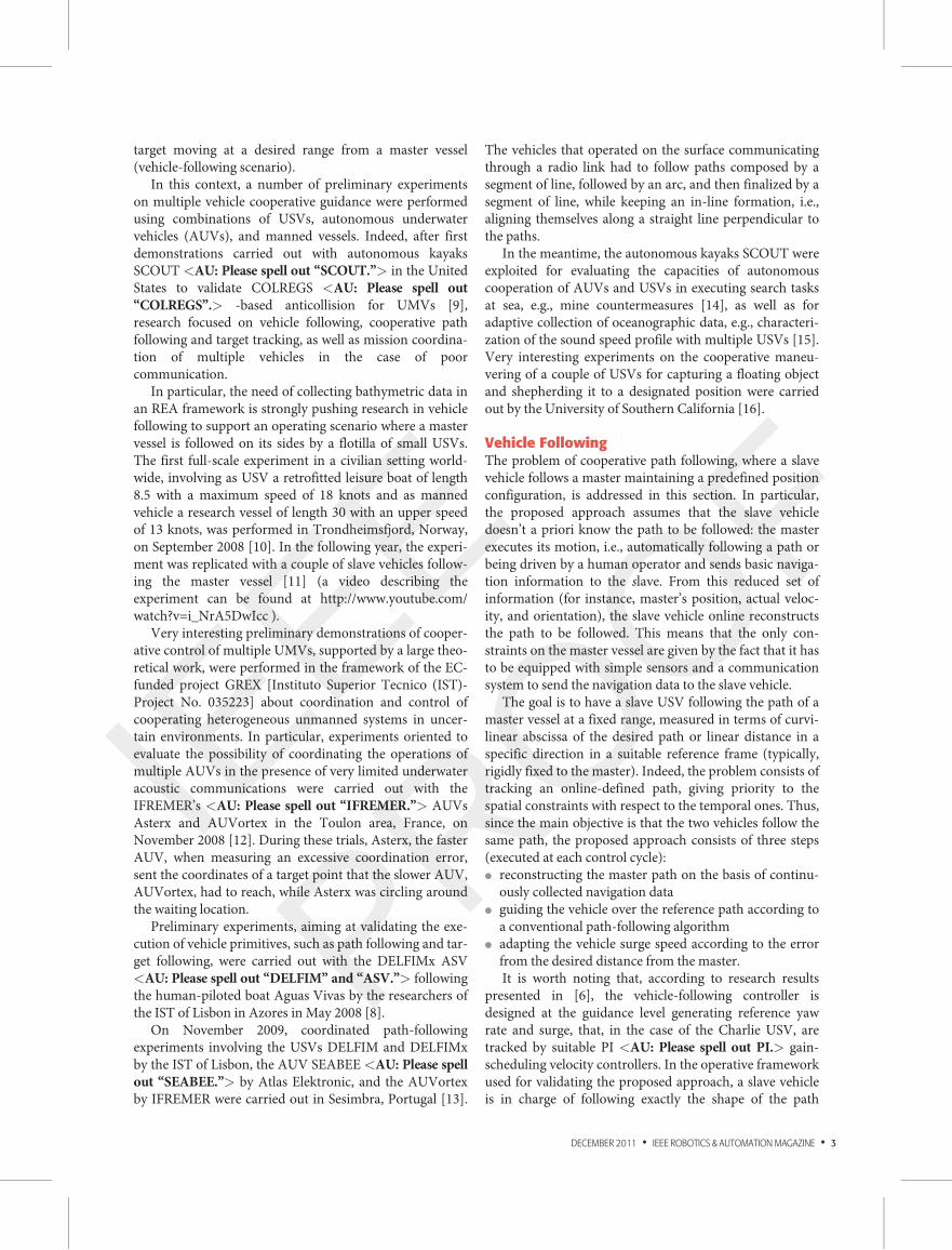
Virtual Target-Based Path FollowingA brief description of the adopted path-following guidancealgorithm for a single vehicle system follows. All the detailsof the proposed technique can be found in [6]. With refer-ence to Figure 1, a Serret-Frenet frame < f > is attachedto a virtual target VT moving along the path. The errorvector connecting the virtual target VT to the vehicleV, expressed in < f >, is d ¼ ½s1 y1�
T<PE: As variables “d
and x” were underlined in the author pdf, we have fol-
lowed the same. Please check.>. Thus, after straightfor-ward computations, on the horizontal plane the errordynamics is given by the following equation system:
_s1 ¼ �_s 1� ccy1ð Þ þ U cos b,_y1 ¼ �cc_ss1 þ U sin b,_b ¼ re � cc _s,
8
<
:
(1)
where b ¼ we � wf is the angle of approach to the path, r�
and re are, respectively, the rotation rates of the vehicle andits velocity vector, which has a absolute value U , s repre-sents the position of the virtual target VT over the path(i.e., curvilinear abscissa), and cc ¼ cc(s) is the signedcurvature of the path. Defining the Lyapunov functionV ¼ 1
2(b� u)2, the following control law for the yaw-rate
input signal is obtained:
r� ¼1
g(t)_u� k1(b� u)þ cc_s½ �, (2)
where g(t) embeds the ratio between the angular speed ofthe vehicle’s velocity vector and the vehicle’s yaw rate, k1 isa controller parameter, and u is an odd function definingthe actual angle approach, as a function of the distance y1from the path. A typical choice of u y1ð Þ is
u y1ð Þ ¼ �wa tanh kuy1� �
, (3)
where wa is the maximum approach angle value and ku isa tunable function parameter. Moreover, it is worth notingthat the speed _s of the target Serret-Frenet frame < f >constitutes an additional degree of freedom that can becontrolled to guarantee the convergence of the vehicle atthe desired path avoiding possible singularities. Indeed, themotion of the feedback control system restricted to the setE, where _V ¼ 0, i.e., b ¼ u y1ð Þ, can be studied definingthe Lyapunov function VE ¼ (1=2) s21 þ y21
� �
. Consideringthat in the set E y1 sinu y1ð Þ � 0 for the choice of u y1ð Þ in(3), the regulation law for the virtual target speed is com-puted as follows:
_s� ¼ U cos bþ k2s1: (4)
Vehicle Range TrackingAs introduced previously, the vehicle-following approachproposed in this work is based on the single-vehicle path-following guidance technique (2), combined with thecontinuous adaptation of the surge speed of the slave vehi-cle, with the aim of forcing the intervehicle distance to con-verge to and be maintained at a desired value.
The intervehicle distance D can be defined in differentways according to the mission requirements: the mostcommon establishes the linear range between the vehicles,i.e., D ¼ kxmaster � xslavek<PE: Please specify whether
underline should be removed.>, or the curvilinear dis-tance between the master and slave, i.e., the differencebetween the respective curvilinear abscissas D ¼ Ds ¼smaster � sslave. Thus, the range tracking task consists ofdesigning a control law to reach a desired distance D�.Defining the distance error es ¼ D� D�, the simplestimplemented solution to make es ! 0 is a PI control lawthat generates a surge speed reference signal u�. This basic
B
U
<b>
<f>
<e>
ψf
ψe
ψ
d
x
P
p
xe
ye
Figure 1. Vehicle’s parameters and frames definition.
4 • IEEE ROBOTICS & AUTOMATIONMAGAZINE • DECEMBER 2011
IEEE
PROOF
solution can be easily improved by introducing a continu-ous saturation function to constrain the computed surge-speed reference within a minimum and maximum value,generating a feasible reference signal u�sat for the lowerorder surge speed controller:
u� ¼ uff þ Kpes þ Ki
R
esdt,u�sat ¼ C þ umax�umin
2tanh ku� � Cð Þ
�
, (5)
where Kp and Ki are, respectively, the proportional andintegral gains of the controller, k is a gain factor, andC ¼ umin þ ((umax � umin)=2). The feed forward of thevelocity of the master vehicle uff can be transmitteddirectly from the vessel itself or computed by the slaveusing, for instance, classic numerical derivation or somesort of filter. A minimum surge speed limit umin, usuallygreater than zero, is needed to guarantee maneuverability,whereas the maximum speed limit umax takes into accountthe physical constraints of the thrust actuation.
Sensing IssuesAs introduced previously, the motion of the master andslave vehicles is estimated online on the basis of themeasurements of aboard GPS and compass. Depending onthe quality of the sensor measurements, issues in thesmoothness of the estimated path or in the ground truth-ing of the estimated positions of the vehicles can turn up.l Estimation of the target path: The steering control
action, which is a function of the master path tangentand curvature as in (2), can be affected by the noise intheir estimates. Indeed, a direct computation of the pathtangent and curvature amplifies the noise of the GPSposition measurements. Anyway, when the slave vehiclecan be assumed to keep a certain distance from themaster, a local smoothing for estimating the referencepath is possible, thus reducing the impact of disturbancein position measurements. On the other hand, wherethe vehicles are required to maintain a parallel forma-tion, only causal filtering techniques can be used for esti-mating the master’s path.
l Consistency of position measurements: Althoughadvanced guidance techniques usually guarantee thata vehicle follows a path with a desired precision, this istrue for the estimated position of the vehicle that, as aconsequence of disturbance on GPS measurements,could differ from the actual one also of some meters.Indeed, when a slave vehicle is required to follow thepath of a master vehicle to collect data in the same pla-ces, the precision in executing this task is not only afunction of the performance of the guidance and con-trol modules but also of the consistency of the positionmeasurements collected aboard the two vehicles.Thus, special attention to ground-truth verificationof the followed path has to be paid when performingfield trials.
Experimental SetupExperiments have been carried out with the Charlie USVand ALANIS dual-mode vessel in a rowing regatta fieldinside the Genova Pr�a harbor, Italy, on July 2009. Accordingto the requirements specified by the Hydrographic Instituteof the Italian Navy, the experiments focused on the high-precision vehicle following to provide, although in a pro-tected environment, a preliminary feasibility demonstrationof the proposed technology and to validate the basic architec-ture requirements in terms of control, communication, andsensing systems. In the following, after a short introductionof the basic characteristics of the vehicles involved in thedemonstration, a detailed presentation of their adaptation,required to support the experiments, will be given togetherwith a description of the adopted navigation sensors.
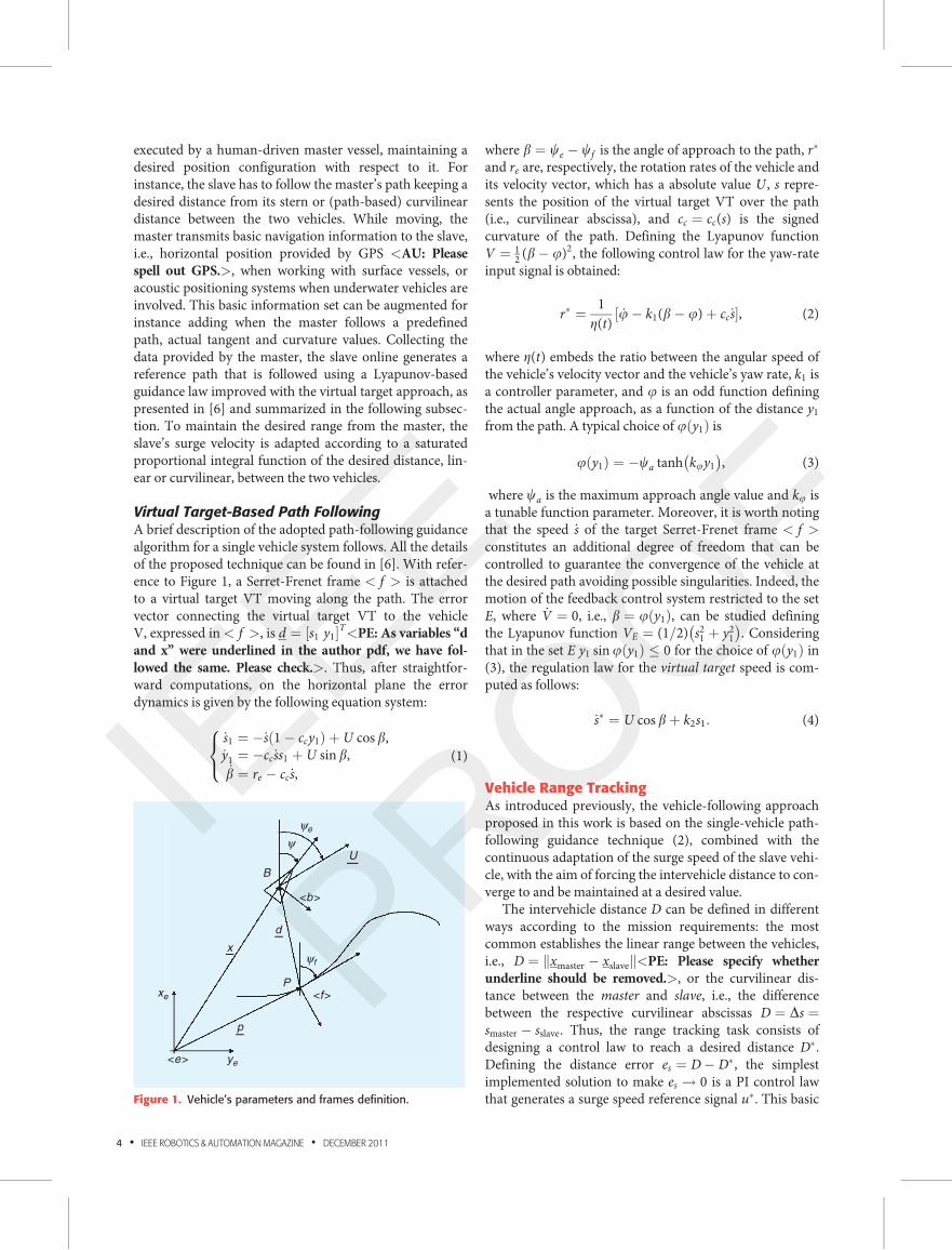
Charlie USVThe Charlie USV [4] is a small autonomous catamaranprototype that is 2.40 m long, 1.70 m wide, and weighsabout 300 kg in air (see Figure 2). The vessel, originallydesigned and developed by CNR-ISSIA, Genova, for sam-pling sea surface microlayer and collecting data on the air–sea interface in Antarctica, is propelled by two dc thrusterswhose revolution rate is controlled by a couple of servoamplifiers, closing a hardware speed control loop with timeconstant negligible with respect to the system.With respectto the original version, where steering was guaranteed bythe differential revolution rate of the propellers, the vehiclehas been upgraded with a rudder-based steering systemconstituted by two rigidly connected rudders, positionedbehind the propellers, and actuated by a brushless motor.The standard vessel navigation package is constituted by aGPS Ashtech GG24C integrated with a KVH <AU: Please
spell out KVH.> Azimuth Gyrotrac providing the truenorth. The electrical power supply is provided by four 12 Vat 40 Ah lead batteries integrated with four 32 W triplejunction, flexible solar panels.
Figure 2. A view of the Charlie USV in the Genova Pr�aharbor.<AU: Please confirm that permission has beengranted by the copyright owner to print this photo andplease provide proper credit line.>
DECEMBER 2011 • IEEE ROBOTICS & AUTOMATIONMAGAZINE • 5
IEEE
PROOF
Communications with the remote control and supervi-sion station are guaranteed by a radio wireless LAN at 2.4GHz with a maximum data transfer rate of 3 Mb/s, sup-porting robot telemetry, operator commands, and videoimage transmission. Owing to poor performance, mainlyin terms of reliability, offered by commercial, relatively lowcost, wireless line-of-sight links, the communication sys-tem has been upgraded with a radio modem working at169 MHz with a transfer rate of 2,400 b/s, guaranteeing asafe transfer of commands and basic telemetry. Indeed, theradio modem link acts as a backup channel, due to the fre-quent and unpredictable main wireless link disconnec-tions, allowing to send a basic command set to drive orrecover the vehicle.
The human operator station is formed by a laptopcomputer, running a human computer interface, imple-mented originally in C++ and then in Java, and the powersupply system, which integrates a couple of solar panels(32 W at 12 V) and one lead battery (100 Ah at 12 V), thus,guaranteeing its full autonomy and portability.
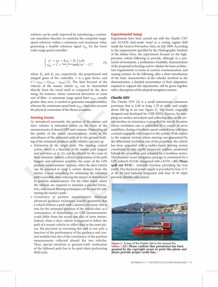
ALANIS Dual-Mode USVThe ALANIS USV [5] is a 4.50-long, 2.20-m wide rubberdinghy-shaped aluminum vessel with a 40 HP Honda out-board motor (see Figure 3). It weighs 600 kg for a loadcapacity of 800 kg and has an autonomy of about 12 hguaranteed by a fuel capacity of 65 L <AU: Please check
whether “65 L” is given correctly.>. A motorized winchcan be mounted on board for automatic deployment andrecovery of scientific instrumentation through a stern holeof 0.20 m diameter. The basic navigation package isformed by a Garmin GPS 152 with 12 parallel channels, anavicontrol smart compass SC1G, and a dual-axis appliedgeomechanics IRIS MD900-TW <AU: Please spell out“IRIS MD900-TW”.> wide-angle clinometer providingaccurate pitch and roll measurements. A manually (dis)-connectible electromechanical system for servoactuatingthe vessel steering and throttle allows the dual use of thevehicle as a manned and an unmanned platform. Indeed,the possibility of having a crew onboard and fast switchingcontrol to a human pilot has been motivated by the lack ofrules for operating unmanned vehicles at sea. For thesereasons, when working in the automatic mode, thehuman–computer interface, which has the same architec-ture as the operator station of the Charlie USV, is keptaboard the vessel itself. The basic navigation, guidance,and control system implemented on a single-boardcomputer-based architecture running GNU/Linux OS<AU: Please spell out “GNU.”> consists of PD <AU:Please spell out “PD.”> auto heading and LOS <AU:
Please spell out “LOS.”> way-point guidance.
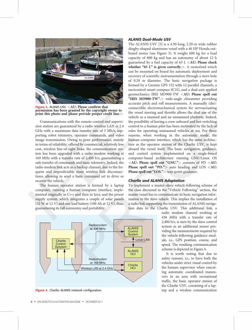
Charlie and ALANIS AdaptationTo implement a master–slave vehicle-following scheme ofthe class discussed in the “Vehicle Following” section, themaster vessel has to communicate its basic navigation infor-mation to the slave vehicle. This implies the installation ofa radio link supporting the transmission of ALANIS naviga-tion data to the Charlie USV. This additional link, a
radio modem channel working at436 MHz with a transfer rate of2,400 b/s, is seen by the slave controlsystem as an additional sensor pro-viding the measurements required bythe vehicle-following guidance mod-ule, i.e., GPS position, course, andspeed. The resulting communicationscheme is depicted in Figure 4.
It is worth noting that due tosafety reasons, i.e., to have both thevehicles under strict visual control bythe human supervisor when execut-ing automatic coordinated maneu-vers in an area with recreationaltraffic, the basic operator station ofthe Charlie USV, consisting of a lap-top and a wireless communication
Figure 3. ALANIS USV. <AU: Please confirm thatpermission has been granted by the copyright owner toprint this photo and please provide proper credit line.>
Radiomodem
at 436 MHz
Radiomodem
at 169 MHz
Wireless LAN at 2.4 GHz
CharlieControl
Sysytem
ALANISControlSystem
ALANISHCI
Local LAN
CharlieHCI
Figure 4. Charlie–ALANIS network configuration.
6 • IEEE ROBOTICS & AUTOMATIONMAGAZINE • DECEMBER 2011
IEEE
PROOF
link, has been mounted onboard the ALANIS vessel toperform the experiments. Moreover, to improve the local-ization performance and navigation accuracy, accordingto the issues discussed in the “Sensing Issues” section, thetwo vehicles have been equipped with a couple of Omnis-tar HP-8300 high-positioning GPS receivers with a 95%accuracy, supplied by the Hydrographic Institute of theItalian Navy.
Test SiteExperimental tests have been carried out in the GenovaPr�a harbor, a calm water channel devoted to rowing races(44�2503200 N, 8�4604800 E), at the end of July 2009, in a daywith no significant wind disturbance. As shown in the fol-lowing, the presence of white buoys delimiting the lines ofthe regatta field has been very useful for visual ground-truth evaluation of the system performance.
Experimental ResultsField trials, aiming at validating the proposed approach,have been carried out with the slave Charlie USV followingthe master ALANIS vessel piloted by a human operator. Asdiscussed previously, the master vessel sends to the slavevehicle its fundamental navigation data (position, course,and speed). The result is that the slave follows the actualpath of the master at less errors than in the intercalibrationof the GPS receivers mounted on the two vehicles. Toexperimentally evaluate the amount of this intercalibrationerror using GPS devices of different classes, dedicatedpreliminary tests have been performed.
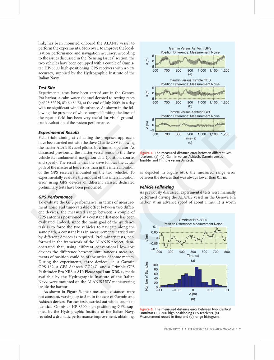
GPS PerformanceTo evaluate the GPS performance, in terms of measure-ment noise and time-variable offset between two differ-ent devices, the measured range between a couple ofGPS antennas positioned at a constant distance has beenevaluated. Indeed, since the main goal of the guidancetask is to force the two vehicles to navigate along thesame path, a constant bias in measurements carried outby different devices is required. Preliminary tests, per-formed in the framework of the ALANIS project, dem-onstrated that, using different conventional low-costdevices the difference between simultaneous measure-ments of position could be of the order of some meters.During the experiments, three devices, i.e. a GarminGPS 152, a GPS Ashtech GG24C, and a Trimble GPSPathfinder Pro XRS <AU: Please spell out XRS.>, madeavailable by the Hydrographic Institute of the ItalianNavy, were mounted on the ALANIS USV maneuveringinside the harbor.
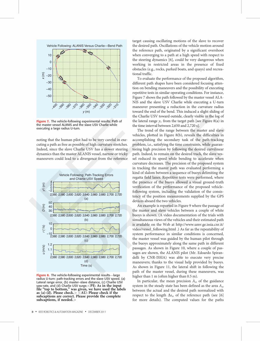
As shown in Figure 5, their measured distances werenot constant, varying up to 5 m in the case of Garmin andAshtech devices. Further tests, carried out with a couple ofidentical Omnistar HP-8300 high-positioning GPS, sup-plied by the Hydrographic Institute of the Italian Navy,revealed a dramatic performance improvement, obtaining,
as depicted in Figure 6(b), the measured range errorbetween the devices that was always lower than 0.1 m.
Vehicle FollowingAs previously discussed, experimental tests were manuallyperformed driving the ALANIS vessel in the Genova Pr�aharbor at an advance speed of about 1 m/s. It is worth
600 700 800 900 1,000 1,100 1,200
600 700 800 900 1,000 1,100 1,200
600 700 800 900 1,000 1,100 1,200
−5
0
5
Garmin Versus Ashtech GPS
Position Difference: Measurement Noise
d (
m)
−5
0
5
Garmin Versus Trimble GPS
Position Difference: Measurement Noise
d (
m)
−5
0
5
Trimble Versus Ashtech GPS
Position Difference: Measurement Noise
(a)
(b)
Time (s)
(c)
d (
m)
Figure 5. The measured distance error between different GPSreceivers. (a)–(c): Garmin versus Ashtech, Garmin versusTrimble, and Trimble versus Ashtech.
200 300 400 500 600 700 800−0.1
−0.05
0
0.05
0.1
Omnistar HP−8300
Position Difference: Measurement Noise
Time (s)
d (
m)
−0.1 −0.05 0 0.05 0.10
20
40
60
80
100
d (m)
(a)
(b)
Num
ber
of S
am
ple
s
Figure 6. The measured distance error between two identicalOmnistar HP-8300 high-positioning GPS receivers. (a)Measurement record in time and (b) range histogram.
DECEMBER 2011 • IEEE ROBOTICS & AUTOMATIONMAGAZINE • 7
IEEE
PROOF
noting that the human pilot had to be very careful in exe-cuting a path as free as possible of high curvature stretches.Indeed, since the slave Charlie USV has a slower steeringdynamics than the master ALANIS vessel, narrow or trickymaneuvers could lead to a divergence from the reference
target causing oscillating motions of the slave to recoverthe desired path. Oscillations of the vehicle motion aroundthe reference path, originated by a significant overshootwhen converging to a path at a high speed with respect tothe steering dynamics [6], could be very dangerous whenworking in restricted areas in the presence of fixedobstacles (e.g., rocks, parked boats, and quays) and recrea-tional traffic.
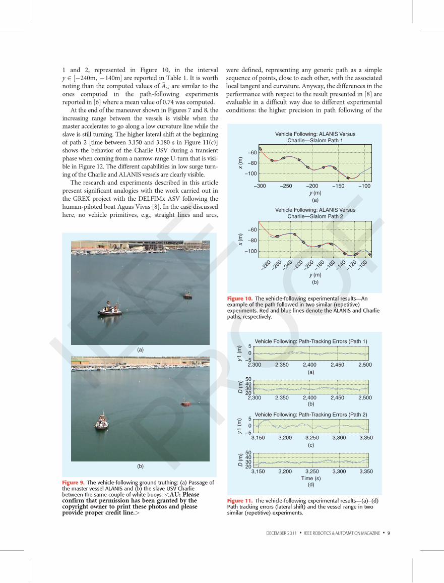
To evaluate the performance of the proposed algorithm,different path shapes have been considered focusing atten-tion on bending maneuvers and the possibility of executingrepetitive tests in similar operating conditions. For instance,Figure 7 shows the path followed by the master vessel ALA-NIS and the slave USV Charlie while executing a U-turnmaneuver presenting a reduction in the curvature radiustoward the end of the bend. This induced a slight sliding ofthe Charlie USV toward outside, clearly visible in the log ofthe lateral range y1 from the target path [see Figure 8(a) inthe time interval between 2,650 and 2,720 s].
The trend of the range between the master and slavevehicles, plotted in Figure 8(b), reveals the difficulties inaccomplishing the secondary task of the path-trackingproblem, i.e., satisfying the time constraints, while guaran-teeing high precision by following the desired curvilinearpath. Indeed, to remain on the desired track, the slave ves-sel reduced its speed while bending to accelerate whencurvature decreases. The precision of the proposed systemin tracking the master path was evaluated performing akind of slalom between a sequence of buoys delimiting theregatta field lanes. Repetitive tests were performed, wherethe presence of the buoys allowed a visual ground-truthverification of the performance of the proposed vehicle-following system, including the validation of the consis-tency of the position measurements supplied by the GPSdevices aboard the two vehicles.
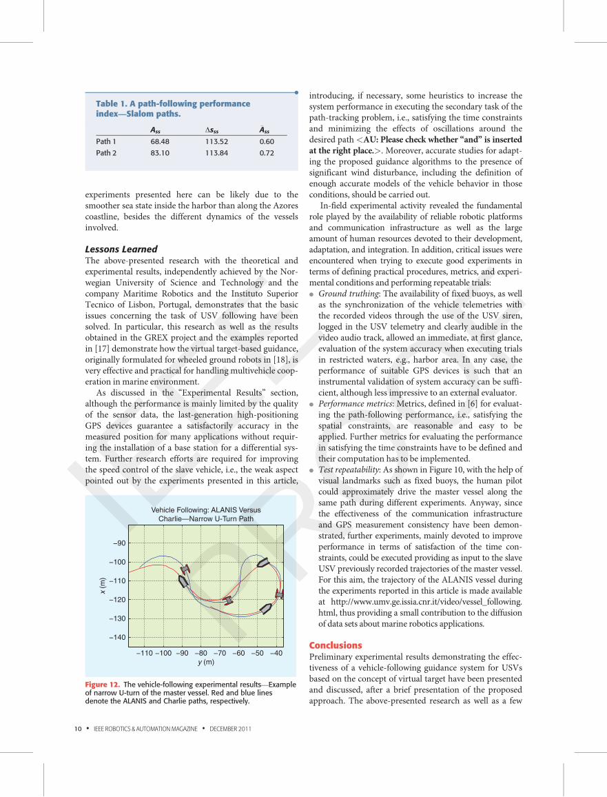
An example is reported in Figure 9 where the passage ofthe master and slave vehicles between a couple of whitebuoys is shown. (A video documentation of the trials withsimultaneous views of the vehicles and their estimated pathis available on the Web at http://www.umv.ge.issia.cnr.it/video/vessel_following.html .) As far as the repeatability ofsystem performance in similar conditions is concerned,the master vessel was guided by the human pilot throughthe buoys approximately along the same path in differentpassages. As shown in Figure 10, where a couple of pas-sages are shown, the ALANIS pilot (Mr. Edoardo Spiran-delli by CNR-ISSIA) was able to execute very precisemaneuvers; thanks to the visual help provided by buoys.As shown in Figure 11, the lateral shift in following thepath of the master vessel, during these maneuvers, washigher than 1 m (often higher than 0.5 m).
In particular, the mean precision �Ass of the guidancesystem in the steady state has been defined as the area Ass
between the actual and the desired path normalized withrespect to the length Dsss of the reference path (see [6]for more details). The computed values for the paths
−400
−390
−380
−370
−360
−350
−340
−330
−320
−310
−50
−40
−30
−20
−10
0
10
Vehicle Following: ALANIS Versus Charlie—Bend Path
y (m)
x (
m)
Figure 7. The vehicle-following experimental results: Path ofthe master vessel ALANIS and the slave USV Charlie whileexecuting a large radius U-turn.
2,560 2,580 2,600 2,620 2,640 2,660 2,680 2,700 2,720
2,560 2,580 2,600 2,620 2,640 2,660 2,680 2,700 2,720
2,560 2,580 2,600 2,620 2,640 2,660 2,680 2,700 2,720
2,560 2,580 2,600 2,620 2,640 2,660 2,680 2,700 2,720
−2024
Vehicle Following: Path-Tracking Errors
and Charlie USV Speed
y1 (
m)
30
40
50
D (
m)
−10
0
10
r (°
/s)
1
1.1
1.2
(d)
Time (s)
(c)
(b)
(a)
u (
m/s
)
Figure 8. The vehicle-following experimental results—largeradius U-turn: path-tracking errors and the slave USV speed. (a)Lateral range error, (b) master–slave distance, (c) Charlie USVyaw-rate, and (d) Charlie USV surge.<PE: As in the inputfile “top to bottom,” was given, we have used the labelsas (a)-(d). Please check.> <AU: Please check if thesubcaptions are correct. Please provide the completesubcaptions, if needed.>
8 • IEEE ROBOTICS & AUTOMATIONMAGAZINE • DECEMBER 2011
IEEE
PROOF
1 and 2, represented in Figure 10, in the intervaly 2 �240m, �140m½ � are reported in Table 1. It is worthnoting than the computed values of �Ass are similar to theones computed in the path-following experimentsreported in [6] where a mean value of 0.74 was computed.
At the end of the maneuver shown in Figures 7 and 8, theincreasing range between the vessels is visible when themaster accelerates to go along a low curvature line while theslave is still turning. The higher lateral shift at the beginningof path 2 [time between 3,150 and 3,180 s in Figure 11(c)]shows the behavior of the Charlie USV during a transientphase when coming from a narrow-range U-turn that is visi-ble in Figure 12. The different capabilities in low surge turn-ing of the Charlie and ALANIS vessels are clearly visible.
The research and experiments described in this articlepresent significant analogies with the work carried out inthe GREX project with the DELFIMx ASV following thehuman-piloted boat Aguas Vivas [8]. In the case discussedhere, no vehicle primitives, e.g., straight lines and arcs,
were defined, representing any generic path as a simplesequence of points, close to each other, with the associatedlocal tangent and curvature. Anyway, the differences in theperformance with respect to the result presented in [8] areevaluable in a difficult way due to different experimentalconditions: the higher precision in path following of the
(a)
(b)
Figure 9. The vehicle-following ground truthing: (a) Passage ofthe master vessel ALANIS and (b) the slave USV Charliebetween the same couple of white buoys. <AU: Pleaseconfirm that permission has been granted by thecopyright owner to print these photos and pleaseprovide proper credit line.>
2,300 2,350 2,400 2,450 2,500
2,300 2,350 2,400 2,450 2,500
−5
0
5Vehicle Following: Path-Tracking Errors (Path 1)
Vehicle Following: Path-Tracking Errors (Path 2)
y1 (
m)
20304050
D (
m)
3,150 3,200 3,250 3,300 3,350
3,150 3,200 3,250 3,300 3,350
−5
0
5
y1 (
m)
20304050
Time (s)
(b)
(c)
(a)
(d)
D (
m)
Figure 11. The vehicle-following experimental results—(a)–(d)Path tracking errors (lateral shift) and the vessel range in twosimilar (repetitive) experiments.
−300 −250 −200 −150 −100
−100
−80
−60
Vehicle Following: ALANIS Versus
Charlie—Slalom Path 1
Vehicle Following: ALANIS Versus
Charlie—Slalom Path 2
y (m)
y (m)
(a)
(b)
x (
m)
x (
m)
−280
−260
−240
−220
−200
−180
−160
−140
−120
−100
−100
−80
−60
Figure 10. The vehicle-following experimental results—Anexample of the path followed in two similar (repetitive)experiments. Red and blue lines denote the ALANIS and Charliepaths, respectively.
DECEMBER 2011 • IEEE ROBOTICS & AUTOMATIONMAGAZINE • 9
IEEE
PROOF
experiments presented here can be likely due to thesmoother sea state inside the harbor than along the Azorescoastline, besides the different dynamics of the vesselsinvolved.
Lessons LearnedThe above-presented research with the theoretical andexperimental results, independently achieved by the Nor-wegian University of Science and Technology and thecompany Maritime Robotics and the Instituto SuperiorTecnico of Lisbon, Portugal, demonstrates that the basicissues concerning the task of USV following have beensolved. In particular, this research as well as the resultsobtained in the GREX project and the examples reportedin [17] demonstrate how the virtual target-based guidance,originally formulated for wheeled ground robots in [18], isvery effective and practical for handling multivehicle coop-eration in marine environment.
As discussed in the “Experimental Results” section,although the performance is mainly limited by the qualityof the sensor data, the last-generation high-positioningGPS devices guarantee a satisfactorily accuracy in themeasured position for many applications without requir-ing the installation of a base station for a differential sys-tem. Further research efforts are required for improvingthe speed control of the slave vehicle, i.e., the weak aspectpointed out by the experiments presented in this article,
introducing, if necessary, some heuristics to increase thesystem performance in executing the secondary task of thepath-tracking problem, i.e., satisfying the time constraintsand minimizing the effects of oscillations around thedesired path <AU: Please check whether “and” is inserted
at the right place.>. Moreover, accurate studies for adapt-ing the proposed guidance algorithms to the presence ofsignificant wind disturbance, including the definition ofenough accurate models of the vehicle behavior in thoseconditions, should be carried out.
In-field experimental activity revealed the fundamentalrole played by the availability of reliable robotic platformsand communication infrastructure as well as the largeamount of human resources devoted to their development,adaptation, and integration. In addition, critical issues wereencountered when trying to execute good experiments interms of defining practical procedures, metrics, and experi-mental conditions and performing repeatable trials:l Ground truthing: The availability of fixed buoys, as well
as the synchronization of the vehicle telemetries withthe recorded videos through the use of the USV siren,logged in the USV telemetry and clearly audible in thevideo audio track, allowed an immediate, at first glance,evaluation of the system accuracy when executing trialsin restricted waters, e.g., harbor area. In any case, theperformance of suitable GPS devices is such that aninstrumental validation of system accuracy can be suffi-cient, although less impressive to an external evaluator.
l Performance metrics: Metrics, defined in [6] for evaluat-ing the path-following performance, i.e., satisfying thespatial constraints, are reasonable and easy to beapplied. Further metrics for evaluating the performancein satisfying the time constraints have to be defined andtheir computation has to be implemented.
l Test repeatability: As shown in Figure 10, with the help ofvisual landmarks such as fixed buoys, the human pilotcould approximately drive the master vessel along thesame path during different experiments. Anyway, sincethe effectiveness of the communication infrastructureand GPS measurement consistency have been demon-strated, further experiments, mainly devoted to improveperformance in terms of satisfaction of the time con-straints, could be executed providing as input to the slaveUSV previously recorded trajectories of the master vessel.For this aim, the trajectory of the ALANIS vessel duringthe experiments reported in this article is made availableat http://www.umv.ge.issia.cnr.it/video/vessel_following.html, thus providing a small contribution to the diffusionof data sets about marine robotics applications.
ConclusionsPreliminary experimental results demonstrating the effec-tiveness of a vehicle-following guidance system for USVsbased on the concept of virtual target have been presentedand discussed, after a brief presentation of the proposedapproach. The above-presented research as well as a few
•Table 1. A path-following performanceindex—Slalom paths.
Ass Dsss �Ass
Path 1 68.48 113.52 0.60
Path 2 83.10 113.84 0.72
−110 −100 −90 −80 −70 −60 −50 −40
−140
−130
−120
−110
−100
−90
Vehicle Following: ALANIS Versus
Charlie—Narrow U-Turn Path
y (m)
x (
m)
Figure 12. The vehicle-following experimental results—Exampleof narrow U-turn of the master vessel. Red and blue linesdenote the ALANIS and Charlie paths, respectively.
10 • IEEE ROBOTICS & AUTOMATIONMAGAZINE • DECEMBER 2011
IEEE
PROOF
other similar demonstrations cited in the text contribute tobridge the gap between theory and practice in the field ofUMVs encouraging the application of this emergingtechnology not only in military scenarios but also in civil-ian applications.
AcknowledgmentsThis research has been partially funded by the CNR-CNRS<AU: Please spell out “CNR.”> bilateral agreement Coor-dinated mission control for autonomous marine vehiclesand Parco Scientifico e Tecnologico della Liguria s.c.p.a.
The authors thank the Hydrographic Institute of theItalian Navy for supplying high-positioning GPS devicesand participating in the definition of the multivehiclemaneuvers. Moreover, the authors also thank GiorgioBruzzone and Edoardo Spirandelli for their activity in thedevelopment and operation of the ALANIS and CharlieUSVs, Riccardo Mantovani for the video documentationof the experiments, and the personnel of A.S.D.P.S. Pr�aSapello for their kind support to the execution of sea trials.
References[1] A. Pascoal, C. Silvestre, L. Sebastiao, M. Rufino, V. Barroso, J. Gomes,
G. Ayela, P. Coince, M. Cardew, A. Ryan, H. Braithwaite, N. Cardew, J.
Trepte, N. Seube, J. Champeau, P. Dhaussy, V. Sauce, R. Moiti, R. Santos,
F. Cardigos, M. Brussieux, and P. Dando, “Robotic ocean vehicles for
marine science applications: The European ASIMOV project,” in Proc.
Oceans, Providence, RI, Sept. 2000, <AU: Please provide the complete
page range.>.
[2] J. Manley, “Unmanned surface vehicles, 15 years of development,” in
Proc. MTS/IEEE Oceans’08, Quebec City, Canada, Sept. 2008 <AU:
Please provide the complete page range.>.
[3] L. Gasperini, “Extremely shallow-water morphobathymetric surveys:
The Valle Fattibello (Comacchio, Italy) test case,” Marine Geophys. Res.,
vol. 26, pp. 97–107, 2005<AU: Please provide the issue number.>.
[4] M. Caccia, M. Bibuli, R. Bono, G. Bruzzone, G. Bruzzone, and E.
Spirandelli, “Unmanned surface vehicle for coastal and protected water
applications: The Charlie project,” Marine Technol. Soc. J., vol. 41, no. 2,
pp. 62–71, 2007.
[5] M. Caccia, M. Bibuli, and G. Bruzzone, “Aluminim autonomous navi-
gator for intelligent sampling: The ALANIS project,” Sea Technol., 2009
<AU: Please provide the volume and issue number(s) and page
range.>.
[6] M. Bibuli, G. Bruzzone, M. Caccia, and L. Lapierre, “Path-following
algorithms and experiments for an unmanned surface vehicle,” J. Field
Robot., vol. 26, no. 8, pp. 669–688, 2009.
[7] M. Breivik and T. Fossen, “Guidance laws for planar motion control,”
in Proc. 47th IEEE Conf. Decision and Control, Cancun, Mexico, Dec.
2008, pp. 570–577.
[8] A. Aguiar, J. Almeida, M. Bayat, B. Cardeira, R. Cunha, A. H€ausler, P.
Maurya, P. Oliveira, A. Pascoal, A. Pereira, M. Rufino, L. Sebastiao, C.
Silvestre, and F. Vanni, “Cooperative control of multiple marine vehicles,”
in Proc. 8th IFAC Int. Conf. Manoeuvring and Control of Marine Craft,
Guaruj�a, Brasil, Sept. 16–18, 2009, <AU: Please provide the complete
page range.>.
[9] M. Benjamin, J. Curcio, and P. Newman, “Navigation of unmanned
marine vehicles in accordance with the rules of the road,” in IEEE Proc.
Int. Conf. Robotics and Automation, 2006, pp. 3581–3587.
[10] M. Breivik. (2009). Formation control with unmanned surface
vehicles. Centre for Ships and Ocean Structures, Norwegian Univ. Sci.
Technol., Tech. Rep. [Online]. Available: http://www.ivt.ntnu.no/imt/
courses/tmr4240/literature/formation_control_usvs.pdf.
[11] M. Breivik, “Topics in guided motion control of marine vehicles,”
Ph.D. dissertation, Dept. Eng. Cybern., Norwegian Univ. Sci. Technol.
2010.
[12] T. Alves, L. Brignone, M. Schneider, and J. Kalwa, “Communication
infrastructure for fleets of autonomous marine vehicles: concepts and first
results,” in Proc. 8th IFAC Conf. Manoeuvring and Control of Marine
Craft, 2009<AU: Please provide the complete page range.>.
[13] J. Kalwa, “Final results of the European Project GREX: Coordination
and control of cooperating marine robots,” in Proc. 7th IFAC Symp. Intel-
ligent Autonomous Vehicles, 2010 <AU: Please provide the complete
page range.>.
[14] A. Shafer, M. Benjamin, J. Leonard, and J. Curcio, “Autonomous
cooperation of heterogeneous platforms for sea-based search tasks,” in
Proc. Oceans, 2008<AU: Please provide the complete page range.>.
[15] J. Curcio, T. Schneider, M. Benjamin, and A. Patrikalakis,
“Autonomous surface craft provide flexibility to remote adaptive oceano-
graphic sampling and modeling,” in Proc. Oceans, 2008 <AU: Please
provide the complete page range.>.
[16] F. Arrichiello, H. Heidarsson, S. Chiaverini, and G. Sukhatme,
“Cooperative caging using autonomous aquatic surface vehicles,” in Proc.
IEEE Int. Conf. Robotics and Automation, 2010 <AU: Please provide the
complete page range.>.
[17] M. Bibuli, L. Lapierre, and M. Caccia, “Virtual target based coordi-
nated path-following for multi-vehicle systems,” in Proc. 8th IFAC Conf.
Control Applications in Marine Systems, 2010 <AU: Please provide the
complete page range.>.
[18] L. Lapierre, D. Soetanto, and A. Pascoal, “Adaptive, non-singular
path-following of dynamic wheeled robots,” in Proc. 42nd IEEE Conf.
Decision and Control, Maui, HI, Dec. 2003 <AU: Please provide the
complete page range.>.
Marco Bibuli, Istituto di Studi sui Sistemi Intelligentiper l’Automazione, Consiglio Nazionale delle Ricerche,Genova, Italy. E-mail: [email protected].
Massimo Caccia, Istituto di Studi sui Sistemi Intelligentiper l’Automazione, Consiglio Nazionale delle Ricerche,Genova, Italy. E-mail: [email protected].
Lionel Lapierre, Laboratoire d’Informatique, Robotiqueet Micro-�electronique de Montpellier of CNRS, Montpellier, France. E-mail: [email protected].
Gabriele Bruzzone, Istituto di Studi sui Sistemi Intelligentiper l’Automazione, Consiglio Nazionale delle Ricerche,Genova, Italy. E-mail: [email protected].
DECEMBER 2011 • IEEE ROBOTICS & AUTOMATIONMAGAZINE • 11
IEEE
PROOF
•Charlie USV is propelled by
two dc thrusters whose
revolution rate is controlled
by a couple of servo
amplifiers.
•
•USVs are seen as a part of
flotillas of heterogeneous
vehicles executing
large-scale surveys and
supporting REA.
•
•USVs, given their position at
the air–sea interface, can
play a key role both in
relaying radio-frequency
transmissions in air and
acoustic transmissions
undersea.
•
•Field trials, aiming at
validating the proposed
approach, have been
carried outwith the slave
Charlie USV following the
master ALANIS vessel
piloted by a human
operator.
•
•In-field experimental
activity revealed the
fundamental role played by
the availability of reliable
robotic platforms and
communication
infrastructure aswell as the
large amount of human
resources devoted to their
development, adaptation,
and integration
•
12 • IEEE ROBOTICS & AUTOMATIONMAGAZINE • DECEMBER 2011
IEEE
PROOF