Embed Size (px)
Citation preview
Guidance on the Control of Odour and Noise from Commercial Kitchen Exhaust Systems This report was prepared by Netcen on behalf of Department for Environment, Food and Rural Affairs January 2005
This in
formati
on is
out o
f date
and h
as be
en w
ithdra
wn
2
Department for Environment, Food and Rural Affairs Nobel House 17 Smith Square London SW1P 3JR Telephone 020 7238 6000 Website: www.defra.gov.uk © Queen’s Printer and Controller of HMSO 2005 This report was prepared by Netcen on behalf of Department for Environment, Food and Rural Affairs. Copyright in the typographical arrangement and design rests with the Crown. All enquiries relating to the copyright in the work should be addressed to HMSO, The Licensing Division, St Clements House, 2-16 Colegate, Norwich, NR3 1BQ This document is also available on the Defra website. Published electronically by the Department for Environment, Food and Rural Affairs, January 2005. Product code PB 10527
This in
formati
on is
out o
f date
and h
as be
en w
ithdra
wn
3
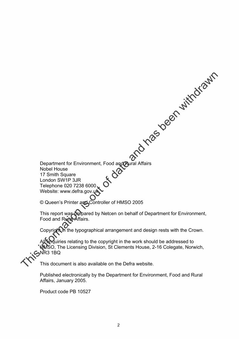
Report Guide
This in
formati
on is
out o
f date
and h
as be
en w
ithdra
wn
4
Contents
Executive Summary 9
1. Introduction 13 1.1 Preamble 13 1.2 Report structure 14
2. Background 15 2.1 Odour 15
2.1.1 Odour and nuisance 15 2.1.2 What is odour? 15 2.1.3 Attributes of odour 16 2.1.4 Effects of odour 16 2.1.5 Physical properties and odour perception 17 2.1.6 Factors that influence magnitude of an odour problem 17 2.1.7 Characteristics of different food types and cooking appliances 17
2.2 Noise 19
2.2.1 Noise and nuisance 19 2.2.2 Properties of noise 20 2.2.3 Types of noise in industrial kitchens 21
2.3 Typical problems encountered with commercial kitchen ventilation systems 23
3. Regulation of kitchen ventilation systems 26 3.1 Role of council officers 26
3.1.1 Regulation in response to submission of a planning application 26 3.1.2 Regulation in response to a noise and/or odour complaint 26 3.1.3 Assessment of whether causing statutory nuisance 26 3.1.4 Regulation in response to a change of use not requiring planning permission 29
3.2 Regulation governing design and performance of ventilation systems 30
3.2.1 Relevant legislation 31 3.2.2 Industry guidance/standards 33 3.2.3 Regulations/guidance relating to fire safety 34
4. Review of common types of kitchen ventilation systems 35 4.1 Overview 35 4.2 Extraction canopy 36
4.2.1 What ventilation systems are used 37 4.2.2 Determining ventilation rates 38 4.2.3 Make-up air 39 4.2.4 Hoods/extract points 41 4.2.5 Ventilated ceilings 43 4.2.6 Materials of construction of canopies 45
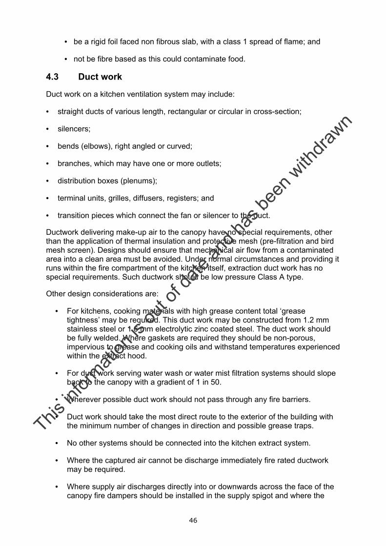
4.3 Duct work 46
This in
formati
on is
out o
f date
and h
as be
en w
ithdra
wn
5
4.4 Dampers 47 4.5 Fans 48 4.6 Access panels for cleaning 51 4.7 Odour abatement tools 52
4.7.1 Coarse or grease filtration 52 4.7.2 Fine filtration 54 4.7.3 Electrostatic precipitation 55 4.7.4 Adsorption 56 4.7.5 Wet scrubbing (absorption) systems 57 4.7.6 In-line oxidation systems 59 4.7.7 Odour neutralising and counteracting agents 59 4.7.8 Stack 60 4.7.9 Summary of grease and odour mitigation measures 63
4.8 Noise attenuation 64 4.9 Fire suppression 66 4.10 Financial considerations 67
4.10.1 Cost of odour abatement equipment 67 4.10.2 Relative cost effectiveness of odour abatement systems 72 4.10.3 Cost of noise abatement equipment 74
4.10.4 Relative cost effectiveness of odour abatement systems 74 4.11 Installation 75
5. Maintenance requirements 76 5.1.1 Consequence of poor maintenance 76
5.1.2 Recommendations for maintenance 77 5.1.3 Maintenance activities 78 5.1.4 Monitoring methods 79
6. Acknowledgement 81 7. References 82 8. Bibliography 84 Annex A: Summary of odour and noise problems encountered by local authority environmental officers.
Annex B: Information required to support planning application for a commercial kitchen.
Annex C: Risk assessment for odour.
Annex D: Factors to take into account in noise assessment.
Annex E: Demonstration photographs (Plates 1-10)
This in
formati
on is
out o
f date
and h
as be
en w
ithdra
wn

6
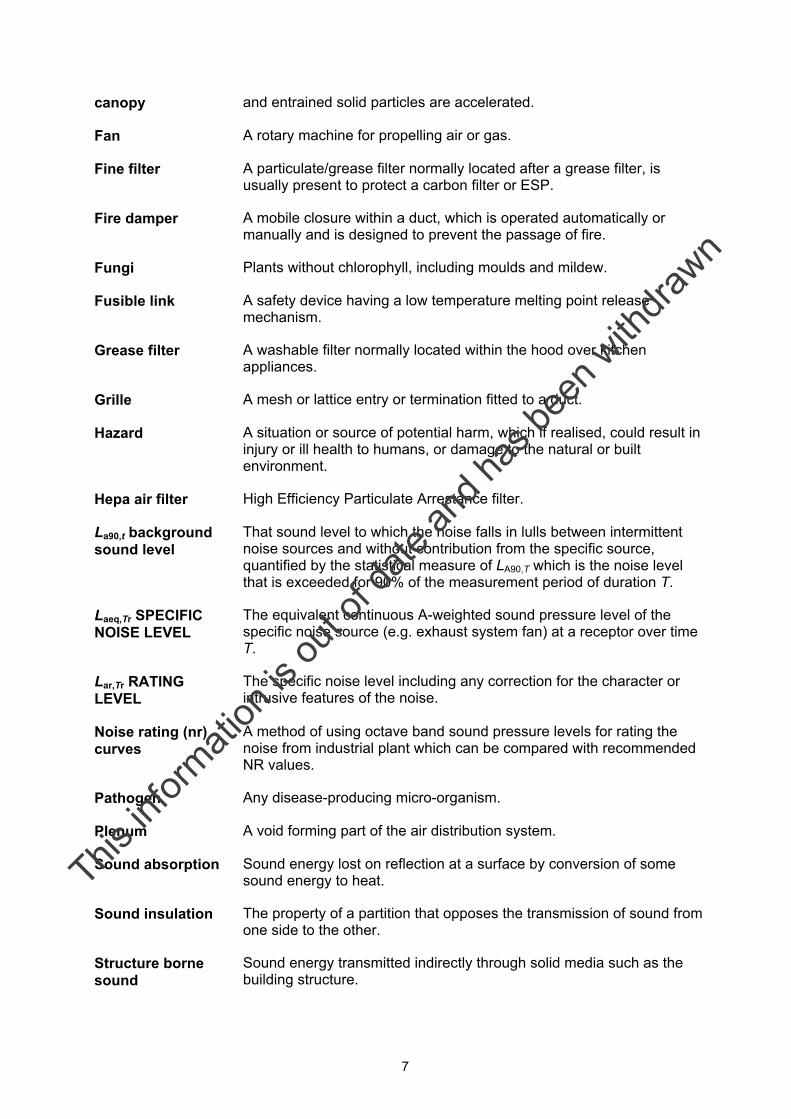
Glossary of Terms Access door A door providing access for maintenance or inspection purposes.
Air borne sound Sound transmitted through the air rather than through the structure of a building or the ground.
Air conditioning A form of air treatment whereby temperature, humidity, ventilation, and air cleanliness are all controlled within limits determined by the requirements of the air-conditioned space.
Air diffuser A supply air terminal device usually placed in the ceiling and generally of circular, square or rectangular shape composed of divergent deflecting parts.
Air filter A mechanical device for removing particulate contaminants from an air stream.
Air handling unit The assembly of air treatment equipment within one casing. It may include filters, fans, humidifier, cooler battery and associated controls.
Balancing The process of adjusting the rates of air flow to achieve specified values.
Carbon filter An air cleaning device, normally using activated carbon for removing gaseous chemicals.
Cassette unit A type of split packaged air conditioning unit in which the internal unit is mounted in the ceiling (recessed into the ceiling void).
Coil A heat-exchanging battery made of tubing formed into a compact shape by spiral or serpentine configuration.
Damper A blade or set of blades that can be moved within a duct in order to control air flow rate.
Detergent A cleansing agent, which may be solvent or water based, for removing dirt.
Dirt Dry dust and debris
Dirt traps Those parts of the system prone to heavy dirt accumulation.
Disinfection A process to reduce micro-organisms to an acceptable level.
Duct An enclosure of any cross-sectional shape, but generally circular or rectangular, through which air can flow.
Ductwork A system of ducts for distribution or extraction of air.
Electrostatic precipitator
A device for removing particulate matter using electrical charge.
Exhaust hood or A hood associated with an extract system into which contaminated air
This in
formati
on is
out o
f date
and h
as be
en w
ithdra
wn
7
canopy and entrained solid particles are accelerated.
Fan A rotary machine for propelling air or gas.
Fine filter A particulate/grease filter normally located after a grease filter, is usually present to protect a carbon filter or ESP.
Fire damper A mobile closure within a duct, which is operated automatically or manually and is designed to prevent the passage of fire.
Fungi Plants without chlorophyll, including moulds and mildew.
Fusible link A safety device having a low temperature melting point release mechanism.
Grease filter A washable filter normally located within the hood over kitchen appliances.
Grille A mesh or lattice entry or termination fitted to a duct.
Hazard A situation or source of potential harm, which if realised, could result in injury or ill health to humans, or damage to the natural or built environment.
Hepa air filter High Efficiency Particulate Arrestance filter.
La90,t background sound level
That sound level to which the noise falls in lulls between intermittent noise sources and without contribution from the specific source, quantified by the statistical measure of LA90,T which is the noise level that is exceeded for 90% of the measurement period of duration T.
Laeq,Tr SPECIFIC NOISE LEVEL
The equivalent continuous A-weighted sound pressure level of the specific noise source (e.g. exhaust system fan) at a receptor over time T.
Lar,Tr RATING LEVEL
The specific noise level including any correction for the character or intrusive features of the noise.
Noise rating (nr) curves
A method of using octave band sound pressure levels for rating the noise from industrial plant which can be compared with recommended NR values.
Pathogen Any disease-producing micro-organism.
Plenum A void forming part of the air distribution system.
Sound absorption Sound energy lost on reflection at a surface by conversion of some sound energy to heat.
Sound insulation The property of a partition that opposes the transmission of sound from one side to the other.
Structure borne sound
Sound energy transmitted indirectly through solid media such as the building structure.
This in
formati
on is
out o
f date
and h
as be
en w
ithdra
wn
8
Abbreviations Used
BCO Building Control Officer
BS British Standard
BSRIA Building Services Research and Information Association
CIBSE Chartered Institute of Building Services Engineers
CIEH Chartered Institute of Environmental Health
Defra Department for Environment, Food and Rural Affairs
EHO Environmental Health Officer
ESP Electrostatic precipitator
HSE Health and Safety Executive
HVAC Heating, Ventilation and Air Conditioning
HVCA Heating and Ventilation Contractors’ Association
NR Noise rating curve
PO Planning Officer
UV Ultra Violet
This in
formati
on is
out o
f date
and h
as be
en w
ithdra
wn
9
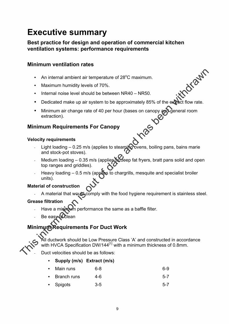
Executive summary Best practice for design and operation of commercial kitchen ventilation systems: performance requirements
Minimum ventilation rates
• An internal ambient air temperature of 28oC maximum.
• Maximum humidity levels of 70%.
• Internal noise level should be between NR40 – NR50.
• Dedicated make up air system to be approximately 85% of the extract flow rate. • Minimum air change rate of 40 per hour (bases on canopy and general room
extraction).
Minimum Requirements For Canopy
Velocity requirements - Light loading – 0.25 m/s (applies to steaming ovens, boiling pans, bains marie
and stock-pot stoves). - Medium loading – 0.35 m/s (applies to deep fat fryers, bratt pans solid and open
top ranges and griddles). - Heavy loading – 0.5 m/s (applies to chargrills, mesquite and specialist broiler
units).
Material of construction - A material that would comply with the food hygiene requirement is stainless steel.
Grease filtration - Have a minimum performance the same as a baffle filter. - Be easy to clean
Minimum Requirements For Duct Work
- All ductwork should be Low Pressure Class ‘A’ and constructed in accordance with HVCA Specification DW/144[1] with a minimum thickness of 0.8mm.
- Duct velocities should be as follows:
• Supply (m/s) Extract (m/s) • Main runs 6-8 6-9
• Branch runs 4-6 5-7
• Spigots 3-5 5-7
This in
formati
on is
out o
f date
and h
as be
en w
ithdra
wn
10
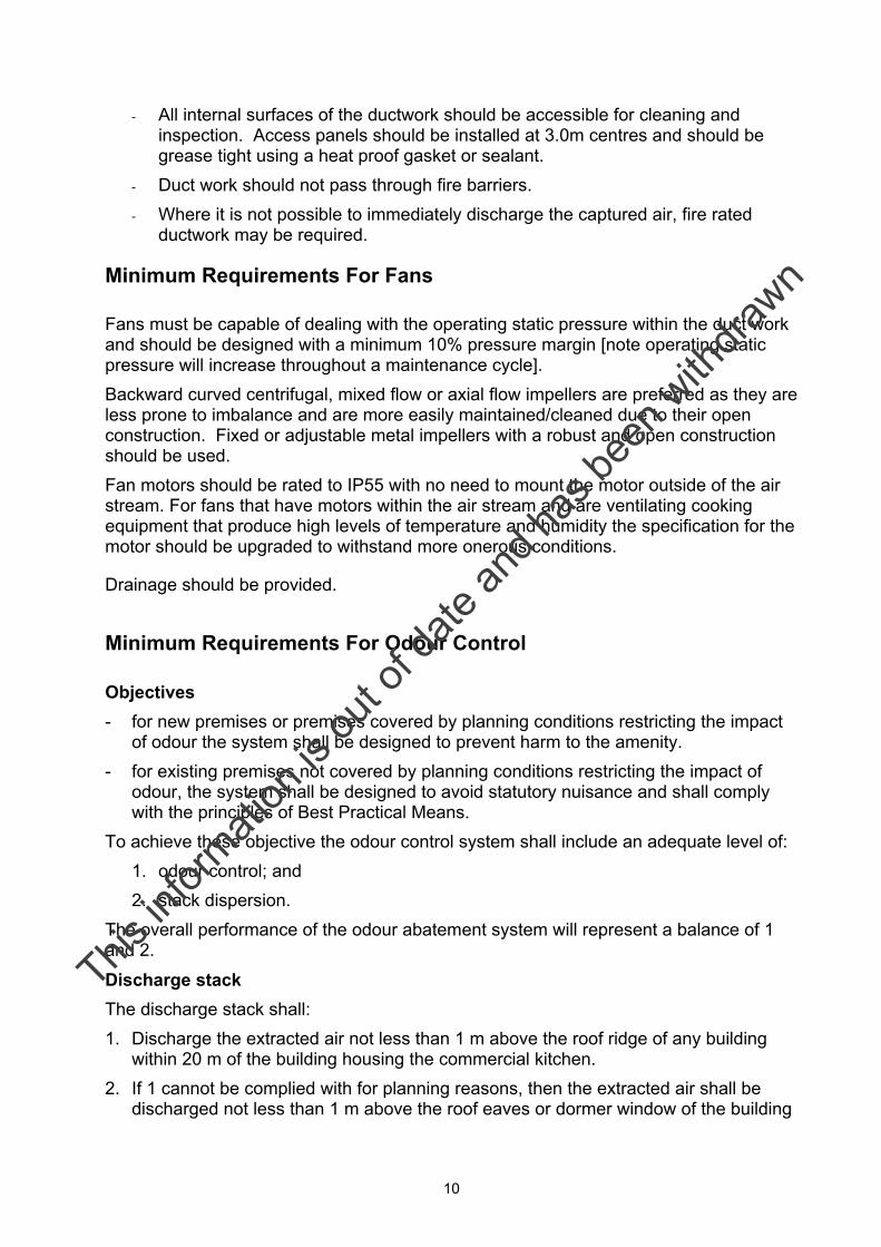
- All internal surfaces of the ductwork should be accessible for cleaning and inspection. Access panels should be installed at 3.0m centres and should be grease tight using a heat proof gasket or sealant.
- Duct work should not pass through fire barriers. - Where it is not possible to immediately discharge the captured air, fire rated
ductwork may be required.
Minimum Requirements For Fans
Fans must be capable of dealing with the operating static pressure within the duct work and should be designed with a minimum 10% pressure margin [note operating static pressure will increase throughout a maintenance cycle]. Backward curved centrifugal, mixed flow or axial flow impellers are preferred as they are less prone to imbalance and are more easily maintained/cleaned due to their open construction. Fixed or adjustable metal impellers with a robust and open construction should be used. Fan motors should be rated to IP55 with no need to mount the motor outside of the air stream. For fans that have motors within the air stream and are ventilating cooking equipment that produce high levels of temperature and humidity the specification for the motor should be upgraded to withstand more onerous conditions.
Drainage should be provided.
Minimum Requirements For Odour Control
Objectives - for new premises or premises covered by planning conditions restricting the impact
of odour the system shall be designed to prevent harm to the amenity. - for existing premises not covered by planning conditions restricting the impact of
odour, the system shall be designed to avoid statutory nuisance and shall comply with the principles of Best Practical Means.
To achieve these objective the odour control system shall include an adequate level of: 1. odour control; and 2. stack dispersion.
The overall performance of the odour abatement system will represent a balance of 1 and 2.
Discharge stack The discharge stack shall: 1. Discharge the extracted air not less than 1 m above the roof ridge of any building
within 20 m of the building housing the commercial kitchen. 2. If 1 cannot be complied with for planning reasons, then the extracted air shall be
discharged not less than 1 m above the roof eaves or dormer window of the building
This in
formati
on is
out o
f date
and h
as be
en w
ithdra
wn
11
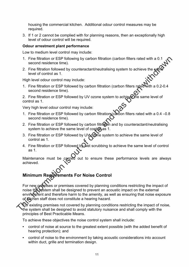
housing the commercial kitchen. Additional odour control measures may be required.
3. If 1 or 2 cannot be complied with for planning reasons, then an exceptionally high level of odour control will be required.
Odour arrestment plant performance Low to medium level control may include: 1. Fine filtration or ESP following by carbon filtration (carbon filters rated with a 0.1
second residence time). 2. Fine filtration followed by counteractant/neutralising system to achieve the same
level of control as 1. High level odour control may include: 1. Fine filtration or ESP followed by carbon filtration (carbon filters rated with a 0.2-0.4
second residence time). 2. Fine filtration or ESP followed by UV ozone system to achieve the same level of control as 1. Very high level odour control may include: 1. Fine filtration or ESP followed by carbon filtration (carbon filters rated with a 0.4 –0.8
second residence time). 2. Fine filtration or ESP followed by carbon filtration and by counteractant/neutralising
system to achieve the same level of control as 1. 3. Fine filtration or ESP followed by UV ozone system to achieve the same level of
control as 1. 4. Fine filtration or ESP followed by wet scrubbing to achieve the same level of control
as 1.
Maintenance must be carried out to ensure these performance levels are always achieved.
Minimum Requirements For Noise Control
For new premises or premises covered by planning conditions restricting the impact of noise the system shall be designed to prevent an acoustic impact on the external environment and therefore harm to the amenity, as well as ensuring that noise exposure of kitchen staff does not constitute a hearing hazard. For existing premises not covered by planning conditions restricting the impact of noise, the system shall be designed to avoid statutory nuisance and shall comply with the principles of Best Practicable Means. To achieve these objectives the noise control system shall include:
• control of noise at source to the greatest extent possible (with the added benefit of hearing protection); and
• control of noise to the environment by taking acoustic considerations into account within duct, grille and termination design.
This in
formati
on is
out o
f date
and h
as be
en w
ithdra
wn
12
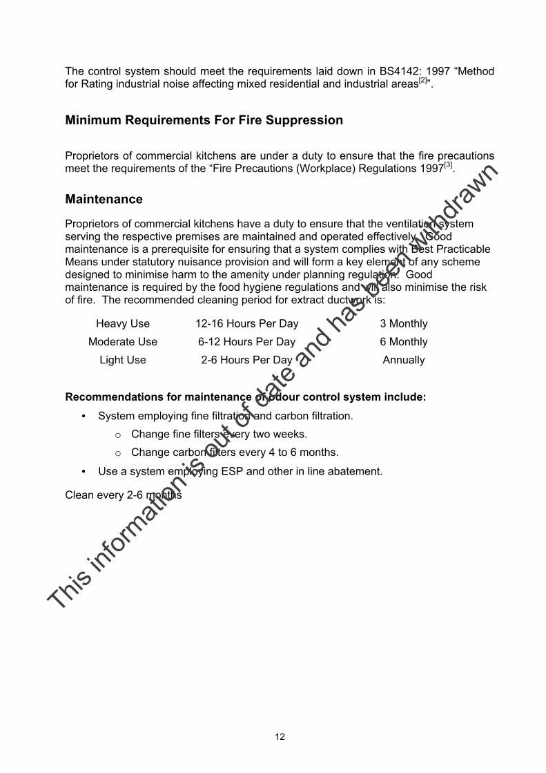
The control system should meet the requirements laid down in BS4142: 1997 “Method for Rating industrial noise affecting mixed residential and industrial areas[2]”.
Minimum Requirements For Fire Suppression
Proprietors of commercial kitchens are under a duty to ensure that the fire precautions meet the requirements of the “Fire Precautions (Workplace) Regulations 1997[3].
Maintenance
Proprietors of commercial kitchens have a duty to ensure that the ventilation system serving the respective premises are maintained and operated effectively. Good maintenance is a prerequisite for ensuring that a system complies with Best Practicable Means under statutory nuisance provision and will form a key element of any scheme designed to minimise harm to the amenity under planning regulation. Good maintenance is required by the food hygiene regulations and will also minimise the risk of fire. The recommended cleaning period for extract ductwork is:
Heavy Use 12-16 Hours Per Day 3 Monthly Moderate Use 6-12 Hours Per Day 6 Monthly Light Use 2-6 Hours Per Day Annually
Recommendations for maintenance of odour control system include:
• System employing fine filtration and carbon filtration. o Change fine filters every two weeks. o Change carbon filters every 4 to 6 months.
• Use a system employing ESP and other in line abatement.
Clean every 2-6 months
This in
formati
on is
out o
f date
and h
as be
en w
ithdra
wn

13
1 Introduction
1.1 Preamble
Problems associated with nuisance odour and noise emissions from commercial kitchen exhausts are very common, particularly in urban areas where housing may be adjacent to or even immediately above catering premises. These premises might include pubs, clubs, restaurants and takeaways that may be open until the early hours of the morning.
Responsibility for the enforcement of statutory controls available to Local Authorities is shared between a number of regulatory functions;
• An authority’s Building Control Officer would usually handle building Regulation requirements relating to the structural safety of installations such as high exhaust flues;
• Planning issues relating to new premises, and to the acceptability and positioning of new ventilation systems that involve the provision of a large flue, are likely to require planning consent, the application for which would be submitted to the Local Planning Authority (or the Planning Service in the Department of the Environment in Northern Ireland);
• Environmental Health Officers providing advice on the odour and noise control aspects of any planning application to the Planning Officers; and
• Environmental Health Officers/Technical Officers would deal with any complaints of statutory nuisance arising from the smell or noise of a kitchen extraction system.
Many kitchen extraction systems are well designed, well maintained and seldom cause nuisance problems. Others can provide a significant and recurring source of nuisance. Currently, there is little advice available to the enforcing officers on what measures may constitute best practicable means for abating the nuisance. Apart from the statutory nuisance aspects, kitchen exhaust system design may also:
• influence the work place environment where temperature and fume control is important; or
• have fire safety and hygiene implications where systems are poorly maintained.
Status of this guidance
This guidance document, prepared by Netcen an operating division of AEA Technology, is sought by Defra, and through it the Devolved Administrations of the Scottish Executive, the National Assembly for Wales, and the Department of the Environment in Northern Ireland to provide clear guidance to the regulation process. Although this guidance is not statutory, it provides information on best practice techniques for the minimisation of odour and noise nuisance from kitchen exhaust systems.
This in
formati
on is
out o
f date
and h
as be
en w
ithdra
wn
14
1.2 Report Structure
This report is structured as follows:
Best Practice Guide summarises the best practice for the design and operation of commercial kitchen ventilation systems and the control of grease, odour and noise emissions (as executive summary).
Section 2 provides:
• a brief overview of odour and noise, illustrating why these parameters can be annoying to members of the public living in the vicinity of commercial kitchens;
• an indication of the composition of the emissions arising from commercial kitchens and types of cooking;
• an indication of the sources of noise from a commercial kitchen; and
• the findings of a survey of Local Authority Officers.
Section 3 provides an overview of the roles of key Local Authority officers who deal with proposed and existing kitchens. The overview summarises the legislative tools available for regulating and setting standards for commercial kitchen design and operation.
Section 4 reviews the range of ventilation systems available, identifying the types of equipment available for the kitchen extraction system through to the control of grease, odour and noise emissions. The review also includes a cost benefit appraisal of remediation measures.
Section 5 presents a practical guide for maintaining kitchen ventilation systems and the associated control equipment.
This report relates to ventilation/extraction systems in all types of premises where hot food is prepared for immediate consumption (other than reheating in microwave ovens).
The views expressed in this document are not necessarily those of Defra. Its officers, servants or agents accept no liability whatsoever for any loss or damage arising from the interpretation or use of the information, or reliance upon the views contained herein.
All references to regulations, standards and guidelines relate to that current at the time of publication. The reader should ensure that they are in possession of the most recent advice when using this document.
This in
formati
on is
out o
f date
and h
as be
en w
ithdra
wn
15
2 Background
2.1 Odour
2.1.1 Odour and nuisance
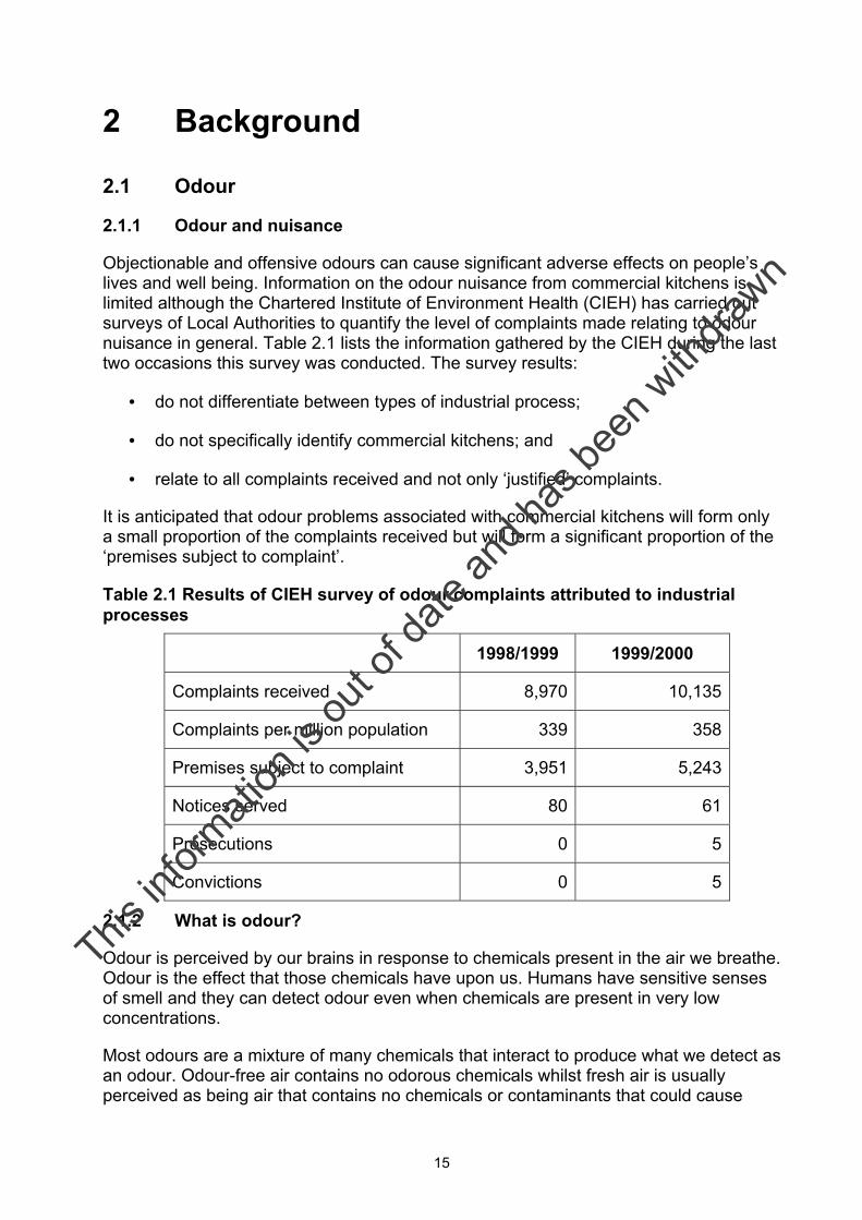
Objectionable and offensive odours can cause significant adverse effects on people’s lives and well being. Information on the odour nuisance from commercial kitchens is limited although the Chartered Institute of Environment Health (CIEH) has carried out surveys of Local Authorities to quantify the level of complaints made relating to odour nuisance in general. Table 2.1 lists the information gathered by the CIEH during the last two occasions this survey was conducted. The survey results:
• do not differentiate between types of industrial process;
• do not specifically identify commercial kitchens; and
• relate to all complaints received and not only ‘justified’ complaints.
It is anticipated that odour problems associated with commercial kitchens will form only a small proportion of the complaints received but will form a significant proportion of the ‘premises subject to complaint’.
Table 2.1 Results of CIEH survey of odour complaints attributed to industrial processes
1998/1999 1999/2000
Complaints received 8,970 10,135
Complaints per million population 339 358
Premises subject to complaint 3,951 5,243
Notices served 80 61
Prosecutions 0 5
Convictions 0 5
2.1.2 What is odour?
Odour is perceived by our brains in response to chemicals present in the air we breathe. Odour is the effect that those chemicals have upon us. Humans have sensitive senses of smell and they can detect odour even when chemicals are present in very low concentrations.
Most odours are a mixture of many chemicals that interact to produce what we detect as an odour. Odour-free air contains no odorous chemicals whilst fresh air is usually perceived as being air that contains no chemicals or contaminants that could cause
This in
formati
on is
out o
f date
and h
as be
en w
ithdra
wn
16
harm, or air that smells “clean”. Fresh air may contain some odour, but these odours will usually be pleasant in character such as the smell of freshly mown grass or sea spray.
Different life experiences and natural variation in the population can result in different sensations and emotional responses by individuals to the same odorous compounds. Because the response to odour is synthesised in our brains, other senses such as sight and taste, and even our upbringing, can influence our perception of odour and whether we find it acceptable, objectionable or offensive.
2.1.3 Attributes of odour
There are four interlinked (sensory) characteristics that are used to describe an odorous emission. These are as follows:
1) Hedonic tone is a judgement of the relative pleasantness or unpleasantness of an odour made by assessors in an odour panel. Outside of a laboratory setting this parameter can be subject to substantial variation between individuals. Some odours may be pleasant when weak but unpleasant when strong, or when exposure is frequent.
2) Quality/Characteristic is a qualitative attribute, which is expressed in terms of “descriptors” (e.g. “oily”, “greasy” or “spicy”). This can be of use when establishing an odour source from complainants’ descriptions. Alternatively, it may be possible to identify key chemical components by a description of their specific odour.
3) Concentration is the “amount” of odour present in a sample of air. It is usually expressed in terms of odour units per cubic metre and is determined using dynamic dilution olfactometry.
4) Intensity may vary between faint to strong. Perceived intensity is the magnitude (strength) of perception of an odour. Increases or decreases in concentration of an odour do not always produce a corresponding proportional change in the odour strength as perceived by the human nose. This can be important for control where an odour has a strong intensity at low concentration as even a low residual odour may cause odour problems.
Odour quality, hedonic tone and concentration influence the perceived odour intensity (and potential for annoyance), although the response to a particular odour will vary between individuals.
2.1.4 Effects of odour
The main concern with odour is its ability to cause an effect that could be considered ‘objectionable or offensive’. An objectionable or offensive effect can occur where an odorous compound is present in very low concentrations, usually far less than the concentration that could cause adverse effects on the physical health of humans or impacts on any other part of the environment.
Effects that have been reported by people include nausea, headaches, retching, difficulty breathing, frustration, annoyance, depression, stress, tearfulness, reduced appetite, being woken in the night and embarrassment in front of visitors. All of these contribute to a reduced quality of life for the individuals who are exposed.
This in
formati
on is
out o
f date
and h
as be
en w
ithdra
wn
17
2.1.5 Physical properties and odour perception
How an odour is perceived and its subsequent effects are not straightforward. The human perception of odour is governed by complex relationships and its properties need to be considered when assessing potential odour effects.
The perception of the intensity of odour in relation to the odour concentration is not a linear but a logarithmic relationship. This means that if the concentration of an odour increases tenfold, the perceived increase in intensity will be by a much smaller amount.
Interactions between mixtures of odorous compounds can also occur. These are known as synergistic effects. An example of a synergistic effect is where one odorous compound disguises or masks the presence of other compounds. As the odour concentration reduces through dilution the nature of the odour may change as different compounds dominate the effect. For example, certain emissions treated with incorrect levels of odour counteracting agents has been observed to have distinctly different odour characteristics at source than when diluted downwind. The odour intensity experienced by an observer is, in general, not equivalent to the sum of the intensities of the component odorous compounds. The perceived intensity may be greater or less than the components depending on the synergistic effects of the compounds present.
Exposure to an odour can result in people becoming desensitised so that they can no longer detect the odour even though the odorous chemical is constantly present in the air. This is sometimes known as olfactory fatigue. For example, people working in an environment with a persistent odour are often unaware of its presence and may not be aware if the odour is having an impact on the surrounding community.
2.1.6 Factors that influence magnitude of an odour problem
Factors that influence the control of odour from commercial kitchens include:
Size of the cooking facility: This influences the intensity of the odour and volume of ventilation air to be handled.
Type of food prepared: This affects the chemical constituents within the ventilation air.
Type of cooking appliances used: This dictates the level of fat, water droplets and temperature within the ventilation air.
2.1.7 Characteristics of different food types and cooking appliances
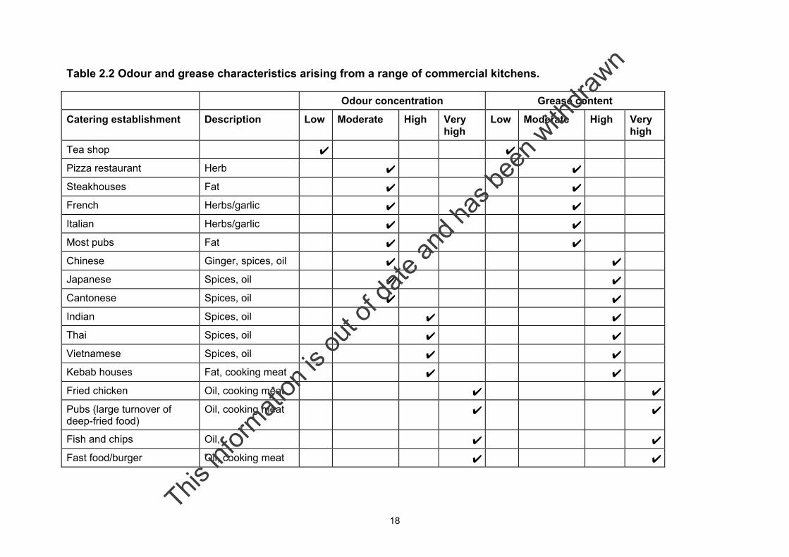
The odour and grease characteristics from a range of commercial kitchen types are summarised in Table 2.2 (CIEH 1996[4]).
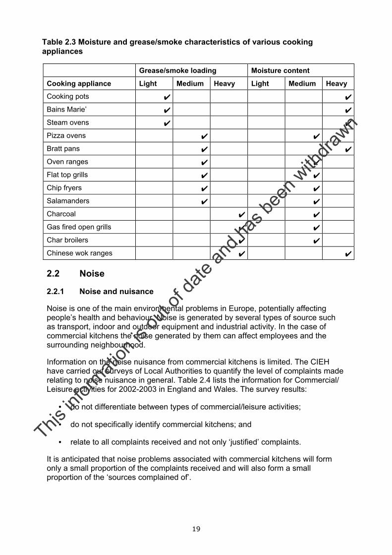
The grease and moisture characteristics anticipated from a range of kitchen appliances are provided in Table 2.3 (LPS, 2003[5]).
This in
formati
on is
out o
f date
and h
as be
en w
ithdra
wn
18
Table 2.2 Odour and grease characteristics arising from a range of commercial kitchens.
Odour concentration Grease content
Catering establishment Description Low Moderate High Very high
Low Moderate High Very high
Tea shop ✔ ✔
Pizza restaurant Herb ✔ ✔
Steakhouses Fat ✔ ✔
French Herbs/garlic ✔ ✔
Italian Herbs/garlic ✔ ✔
Most pubs Fat ✔ ✔
Chinese Ginger, spices, oil ✔ ✔
Japanese Spices, oil ✔ ✔
Cantonese Spices, oil ✔ ✔
Indian Spices, oil ✔ ✔
Thai Spices, oil ✔ ✔
Vietnamese Spices, oil ✔ ✔
Kebab houses Fat, cooking meat ✔ ✔
Fried chicken Oil, cooking meat ✔ ✔
Pubs (large turnover of deep-fried food)
Oil, cooking meat ✔ ✔
Fish and chips Oil, ✔ ✔
Fast food/burger Oil, cooking meat ✔ ✔
This in
formati
on is
out o
f date
and h
as be
en w
ithdra
wn
19
Table 2.3 Moisture and grease/smoke characteristics of various cooking appliances
Grease/smoke loading Moisture content
Cooking appliance Light Medium Heavy Light Medium Heavy
Cooking pots ✔ ✔
Bains Marie’ ✔ ✔
Steam ovens ✔ ✔
Pizza ovens ✔ ✔
Bratt pans ✔ ✔
Oven ranges ✔ ✔
Flat top grills ✔ ✔
Chip fryers ✔ ✔
Salamanders ✔ ✔
Charcoal ✔ ✔
Gas fired open grills ✔ ✔
Char broilers ✔ ✔
Chinese wok ranges ✔ ✔
2.2 Noise
2.2.1 Noise and nuisance
Noise is one of the main environmental problems in Europe, potentially affecting people’s health and behaviour. Noise is generated by several types of source such as transport, indoor and outdoor equipment and industrial activity. In the case of commercial kitchens the noise generated by them can affect employees and the surrounding neighbourhood.
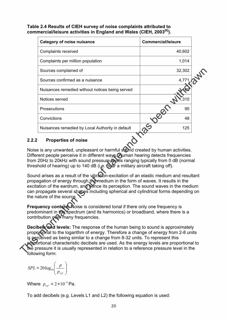
Information on the noise nuisance from commercial kitchens is limited. The CIEH have carried out surveys of Local Authorities to quantify the level of complaints made relating to noise nuisance in general. Table 2.4 lists the information for Commercial/ Leisure activities for 2002-2003 in England and Wales. The survey results:
• do not differentiate between types of commercial/leisure activities;
• do not specifically identify commercial kitchens; and
• relate to all complaints received and not only ‘justified’ complaints.
It is anticipated that noise problems associated with commercial kitchens will form only a small proportion of the complaints received and will also form a small proportion of the ‘sources complained of’.
This in
formati
on is
out o
f date
and h
as be
en w
ithdra
wn
20
Table 2.4 Results of CIEH survey of noise complaints attributed to commercial/leisure activities in England and Wales (CIEH, 2003[6]).
Category of noise nuisance Commercial/leisure
Complaints received 40,602
Complaints per million population 1,014
Sources complained of 32,302
Sources confirmed as a nuisance 4,771
Nuisances remedied without notices being served 3,140
Notices served 1,310
Prosecutions 95
Convictions 48
Nuisances remedied by Local Authority in default 125
2.2.2 Properties of noise
Noise is any unwanted, unpleasant or harmful sound created by human activities. Different people perceive it in different ways. Human hearing detects frequencies from 20Hz to 20kHz with sound pressure levels ranging typically from 0 dB (normal threshold of hearing) up to 140 dB (i.e. near a military aircraft taking off).
Sound arises as a result of the vibration-excitation of an elastic medium and resultant propagation of energy through the medium in the form of waves. It results in the excitation of the eardrum, and hence its perception. The sound waves in the medium can propagate several shapes including spherical and cylindrical forms depending on the nature of the source.
Frequency content: Noise is considered tonal if there only one frequency is predominant in the spectrum (and its harmonics) or broadband, where there is a contribution over many frequencies.
Decibels and levels: The response of the human being to sound is approximately proportional to the logarithm of energy. Therefore a change of energy from 2-8 units is perceived as being similar to a change from 8-32 units. To represent this proportional characteristic decibels are used. As the energy levels are proportional to the pressure it is usually represented in relation to a reference pressure level in the following form:
=
refppSPL 10log20
Where 5102 −×=refp Pa.
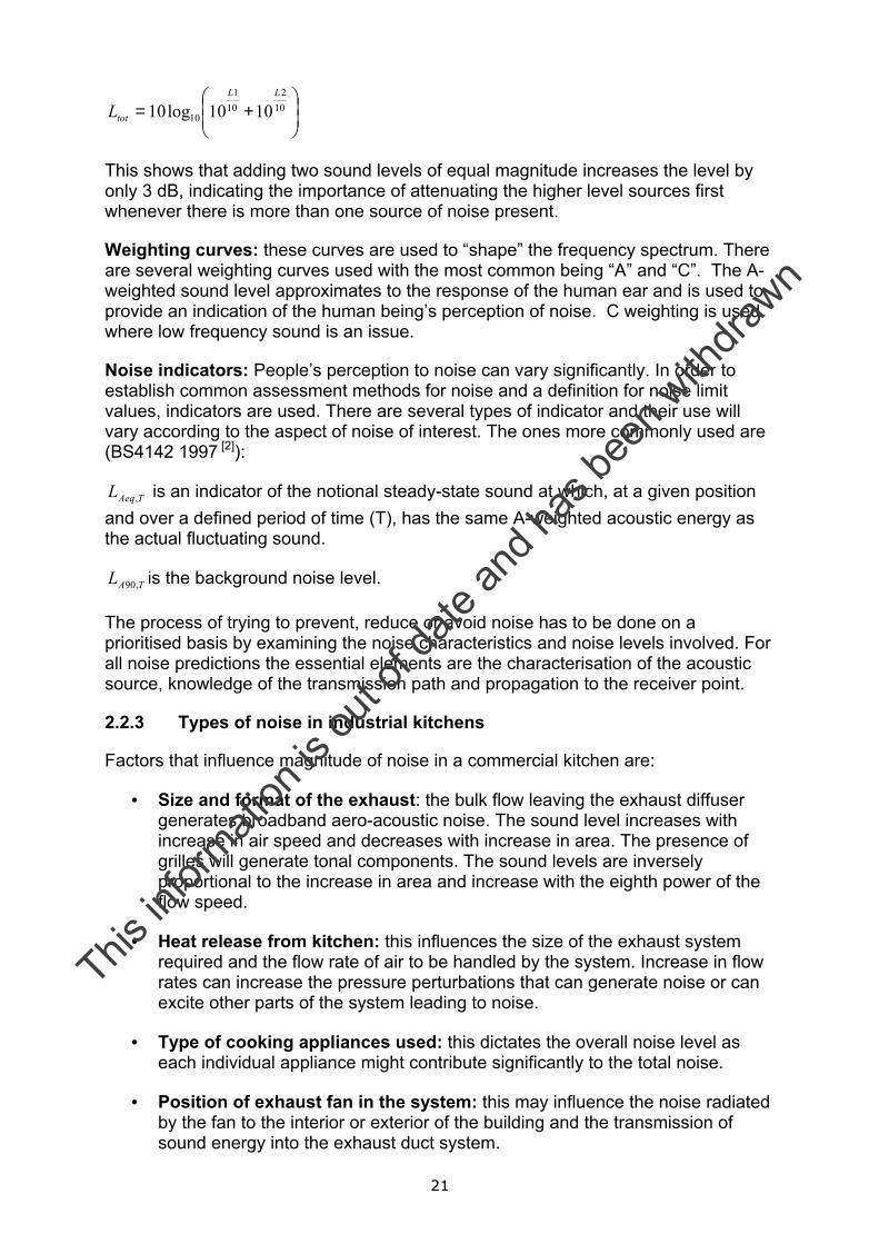
To add decibels (e.g. Levels L1 and L2) the following equation is used:
This in
formati
on is
out o
f date
and h
as be
en w
ithdra
wn
21
+= 10
210
1
10 1010log10LL
totL
This shows that adding two sound levels of equal magnitude increases the level by only 3 dB, indicating the importance of attenuating the higher level sources first whenever there is more than one source of noise present.
Weighting curves: these curves are used to “shape” the frequency spectrum. There are several weighting curves used with the most common being “A” and “C”. The A-weighted sound level approximates to the response of the human ear and is used to provide an indication of the human being’s perception of noise. C weighting is used where low frequency sound is an issue.
Noise indicators: People’s perception to noise can vary significantly. In order to establish common assessment methods for noise and a definition for noise limit values, indicators are used. There are several types of indicator and their use will vary according to the aspect of noise of interest. The ones more commonly used are (BS4142 1997 [2]):
TAeqL , is an indicator of the notional steady-state sound at which, at a given position and over a defined period of time (T), has the same A-weighted acoustic energy as the actual fluctuating sound.
TAL ,90 is the background noise level.
The process of trying to prevent, reduce or avoid noise has to be done on a prioritised basis by examining the noise characteristics and noise levels involved. For all noise predictions the essential elements are the characterisation of the acoustic source, knowledge of the transmission path and propagation to the receiver point.
2.2.3 Types of noise in industrial kitchens
Factors that influence magnitude of noise in a commercial kitchen are:
• Size and format of the exhaust: the bulk flow leaving the exhaust diffuser generates broadband aero-acoustic noise. The sound level increases with increase in air speed and decreases with increase in area. The presence of grilles will generate tonal components. The sound levels are inversely proportional to the increase in area and increase with the eighth power of the flow speed.
• Heat release from kitchen: this influences the size of the exhaust system required and the flow rate of air to be handled by the system. Increase in flow rates can increase the pressure perturbations that can generate noise or can excite other parts of the system leading to noise.
• Type of cooking appliances used: this dictates the overall noise level as each individual appliance might contribute significantly to the total noise.
• Position of exhaust fan in the system: this may influence the noise radiated by the fan to the interior or exterior of the building and the transmission of sound energy into the exhaust duct system.
This in
formati
on is
out o
f date
and h
as be
en w
ithdra
wn
22
• Fitting and dimensions of the exhaust flow ducts: exhaust duct dimensions, fixings and insulation can all influence the amount of noise these structures will transmit and propagate. Selection of appropriate noise attenuating materials, avoidance of flow restrictions, and vibration isolators between the ducts and the fan are some of the aspects to be considered.
• Fan type and speed: Type of fan used (e.g. centrifugal fan with blades that are backward curved, forward curved or radial, or axial fan) will influence the level and nature of noise emitted. The fan characteristic needs to be chosen so that it is operating at its most efficient duty point as this tends to be the region of minimum noise. If fan speed is too high it will be operating away from that point which can lead to increases in level of up to 10 dB, as well as inefficient air management. It is often also desirable acoustically to use larger fans operating at low speeds rather than smaller fans operating at higher speeds
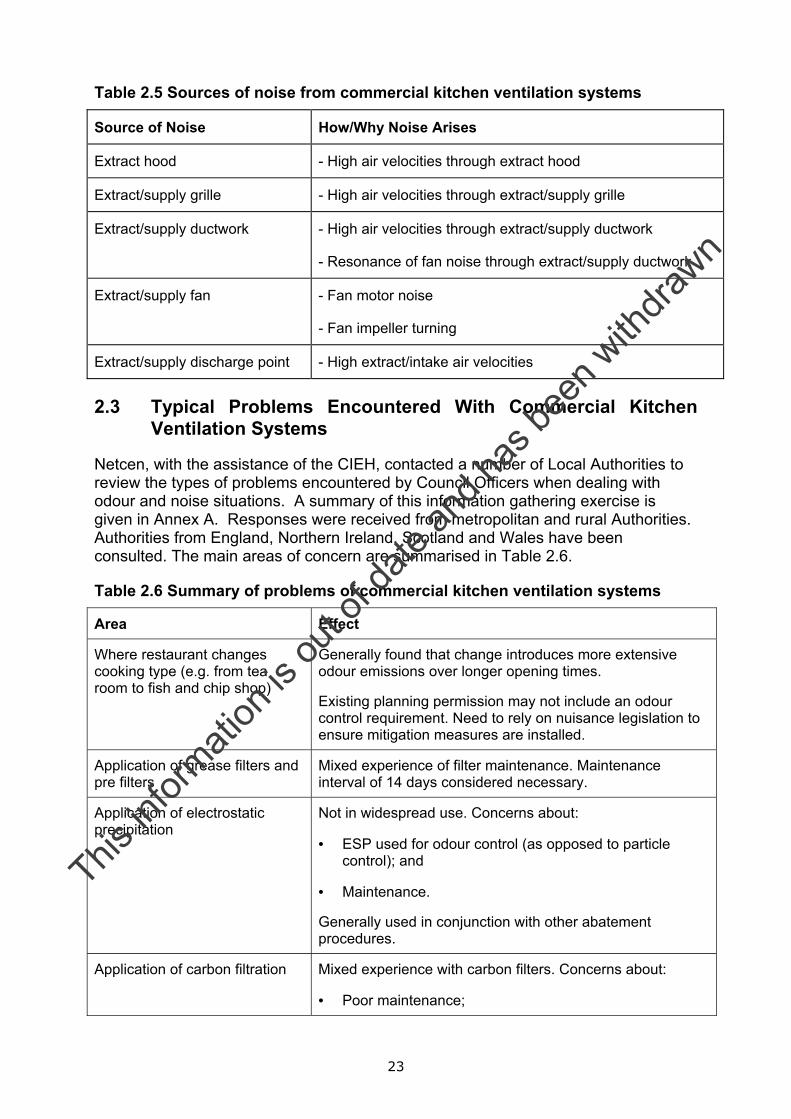
Sources of noise from commercial kitchen ventilation systems are summarised in Table 2.5.
This in
formati
on is
out o
f date
and h
as be
en w
ithdra
wn
23
Table 2.5 Sources of noise from commercial kitchen ventilation systems
Source of Noise How/Why Noise Arises
Extract hood - High air velocities through extract hood
Extract/supply grille - High air velocities through extract/supply grille
Extract/supply ductwork - High air velocities through extract/supply ductwork
- Resonance of fan noise through extract/supply ductwork
Extract/supply fan - Fan motor noise
- Fan impeller turning
Extract/supply discharge point - High extract/intake air velocities
2.3 Typical Problems Encountered With Commercial Kitchen Ventilation Systems
Netcen, with the assistance of the CIEH, contacted a number of Local Authorities to review the types of problems encountered by Council Officers when dealing with odour and noise situations. A summary of this information gathering exercise is given in Annex A. Responses were received from metropolitan and rural Authorities. Authorities from England, Northern Ireland, Scotland and Wales have been consulted. The main areas of concern are summarised in Table 2.6.
Table 2.6 Summary of problems of commercial kitchen ventilation systems
Area Effect
Where restaurant changes cooking type (e.g. from tea room to fish and chip shop)
Generally found that change introduces more extensive odour emissions over longer opening times.
Existing planning permission may not include an odour control requirement. Need to rely on nuisance legislation to ensure mitigation measures are installed.
Application of grease filters and pre filters
Mixed experience of filter maintenance. Maintenance interval of 14 days considered necessary.
Application of electrostatic precipitation
Not in widespread use. Concerns about:
• ESP used for odour control (as opposed to particle control); and
• Maintenance.
Generally used in conjunction with other abatement procedures.
Application of carbon filtration Mixed experience with carbon filters. Concerns about:
• Poor maintenance;
This in
formati
on is
out o
f date
and h
as be
en w
ithdra
wn

24
• Effect on back pressure leading to noise;
• Effect on fan size leading to noise; and
• Maintenance interval of 4 to 6 months considered appropriate
Always used in conjunction with stack for discharge.
This in
formati
on is
out o
f date
and h
as be
en w
ithdra
wn
25
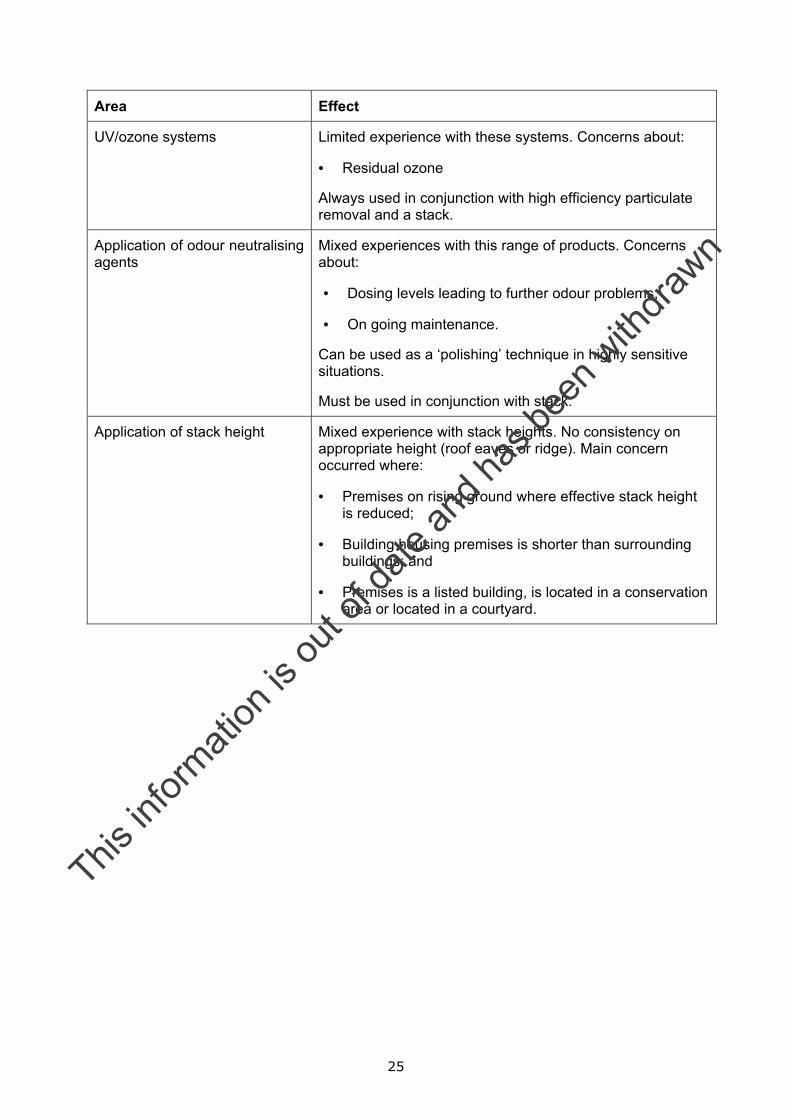
Area Effect
UV/ozone systems Limited experience with these systems. Concerns about:
• Residual ozone
Always used in conjunction with high efficiency particulate removal and a stack.
Application of odour neutralising agents
Mixed experiences with this range of products. Concerns about:
• Dosing levels leading to further odour problems;
• On going maintenance.
Can be used as a ‘polishing’ technique in highly sensitive situations.
Must be used in conjunction with stack.
Application of stack height Mixed experience with stack heights. No consistency on appropriate height (roof eaves or ridge). Main concern occurred where:
• Premises on rising ground where effective stack height is reduced;
• Building housing premises is shorter than surrounding buildings; and
• Premises is a listed building, is located in a conservation area or located in a courtyard.
This in
formati
on is
out o
f date
and h
as be
en w
ithdra
wn
26
3 Regulation of kitchen ventilation systems
3.1 Role of Council Officers
There are three principal officers within the Local Authority (LA) who are involved in the regulation of commercial kitchen exhaust systems in terms of noise and odour. These are:
• Planning;
• Building Control; and
• Environmental Health.
The nature and extent of their role will depend upon the situation that has initiated the process of regulation and could be as a result of any of the following:
• Planning application submitted (new build or change of use);
• Noise or odour complaint has been received; or
• Change of use not requiring a planning application.
The following sections provide a summary of the roles of the Local Authority Officers for each of these situations, and where applicable additional explanation is provided immediately below.
3.1.1 Regulation in response to submission of a planning application
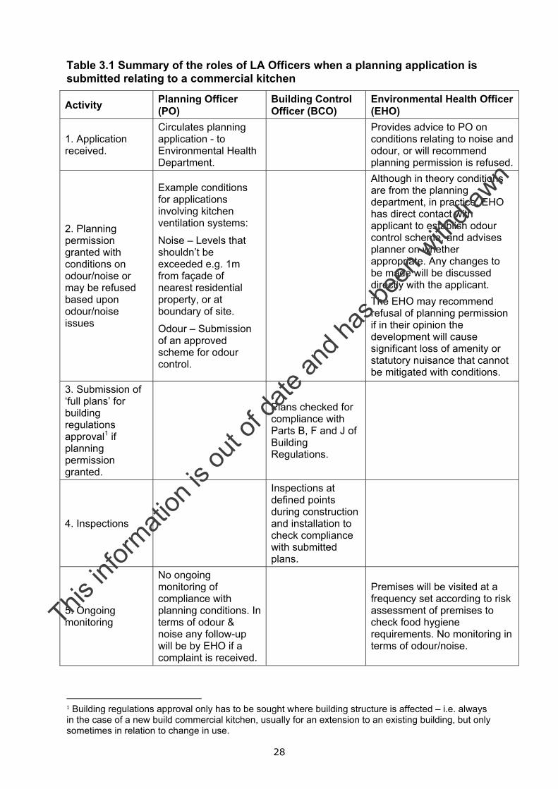
Table 3.1 summarises the roles of the LA Officers in the regulation of commercial kitchens in response to submission of a planning application. This could be in relation to a new build kitchen, a change of use or an extension to an existing commercial kitchen premises requiring planning permission.
Annex B provides examples of information required to support a planning application for a commercial kitchen ventilation system.
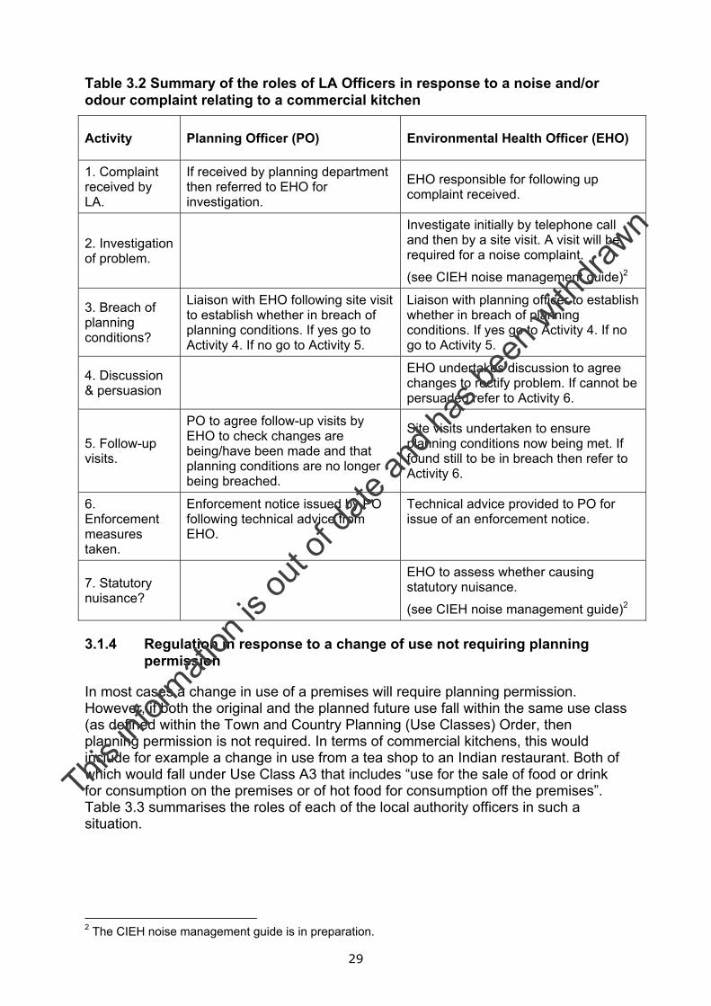
3.1.2 Regulation in response to a noise and/or odour complaint
Table 3.2 summarises the roles of the Planning and Environmental Health Officers in the situation that a noise and/or odour complaint is received by the Local Authority. The Building Control Officer has been omitted from the table because they are not normally involved.
3.1.3 Assessment of whether causing statutory nuisance
Noise
• If planning conditions are not being breached then the noise source would not be expected to be causing a statutory nuisance, since conditions/limits would
This in
formati
on is
out o
f date
and h
as be
en w
ithdra
wn

27
have been set so that statutory nuisance is not caused. Requires further investigation.
Odour
• Planning condition only likely to have been set following a scheme to manage odour. It is possible that the scheme is appropriate, but that its implementation is poor or non-existent. Therefore will need to assess as to whether statutory nuisance is present (see section below for details of statutory nuisance).
This in
formati
on is
out o
f date
and h
as be
en w
ithdra
wn
28
Table 3.1 Summary of the roles of LA Officers when a planning application is submitted relating to a commercial kitchen
Activity Planning Officer (PO)
Building Control Officer (BCO)
Environmental Health Officer (EHO)
1. Application received.
Circulates planning application - to Environmental Health Department.
Provides advice to PO on conditions relating to noise and odour, or will recommend planning permission is refused.
2. Planning permission granted with conditions on odour/noise or may be refused based upon odour/noise issues
Example conditions for applications involving kitchen ventilation systems:
Noise – Levels that shouldn’t be exceeded e.g. 1m from façade of nearest residential property, or at boundary of site.
Odour – Submission of an approved scheme for odour control.
Although in theory conditions are from the planning department, in practice, EHO has direct contact with applicant to establish odour control scheme, and advises planner on whether appropriate. Any changes to be made will be discussed directly with the applicant. The EHO may recommend refusal of planning permission if in their opinion the development will cause significant loss of amenity or statutory nuisance that cannot be mitigated with conditions.
3. Submission of ‘full plans’ for building regulations approval1 if planning permission granted.
Plans checked for compliance with Parts B, F and J of Building Regulations.
4. Inspections
Inspections at defined points during construction and installation to check compliance with submitted plans.
5. Ongoing monitoring
No ongoing monitoring of compliance with planning conditions. In terms of odour & noise any follow-up will be by EHO if a complaint is received.
Premises will be visited at a frequency set according to risk assessment of premises to check food hygiene requirements. No monitoring in terms of odour/noise.
1 Building regulations approval only has to be sought where building structure is affected – i.e. always in the case of a new build commercial kitchen, usually for an extension to an existing building, but only sometimes in relation to change in use.
This in
formati
on is
out o
f date
and h
as be
en w
ithdra
wn
29
Table 3.2 Summary of the roles of LA Officers in response to a noise and/or odour complaint relating to a commercial kitchen
Activity Planning Officer (PO) Environmental Health Officer (EHO)
1. Complaint received by LA.
If received by planning department then referred to EHO for investigation.
EHO responsible for following up complaint received.
2. Investigation of problem.
Investigate initially by telephone call and then by a site visit. A visit will be required for a noise complaint.
(see CIEH noise management guide)2
3. Breach of planning conditions?
Liaison with EHO following site visit to establish whether in breach of planning conditions. If yes go to Activity 4. If no go to Activity 5.
Liaison with planning officer to establish whether in breach of planning conditions. If yes go to Activity 4. If no go to Activity 5.
4. Discussion & persuasion
EHO undertakes discussion to agree changes to rectify problem. If cannot be persuaded refer to Activity 6.
5. Follow-up visits.
PO to agree follow-up visits by EHO to check changes are being/have been made and that planning conditions are no longer being breached.
Site visits undertaken to ensure planning conditions now being met. If found still to be in breach then refer to Activity 6.
6. Enforcement measures taken.
Enforcement notice issued by PO following technical advice from EHO.
Technical advice provided to PO for issue of an enforcement notice.
7. Statutory nuisance?
EHO to assess whether causing statutory nuisance.
(see CIEH noise management guide)2
3.1.4 Regulation in response to a change of use not requiring planning permission
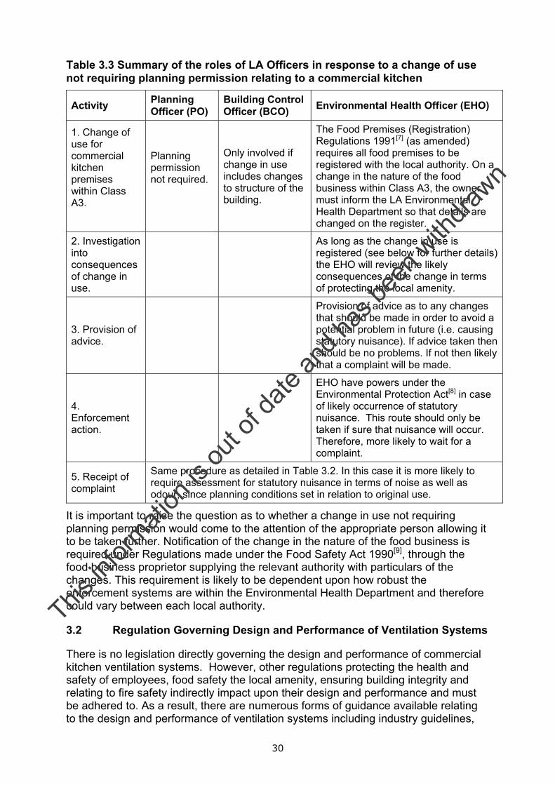
In most cases a change in use of a premises will require planning permission. However, if both the original and the planned future use fall within the same use class (as defined within the Town and Country Planning (Use Classes) Order, then planning permission is not required. In terms of commercial kitchens, this would include for example a change in use from a tea shop to an Indian restaurant. Both of which would fall under Use Class A3 that includes “use for the sale of food or drink for consumption on the premises or of hot food for consumption off the premises”. Table 3.3 summarises the roles of each of the local authority officers in such a situation.
2 The CIEH noise management guide is in preparation.
This in
formati
on is
out o
f date
and h
as be
en w
ithdra
wn
30
Table 3.3 Summary of the roles of LA Officers in response to a change of use not requiring planning permission relating to a commercial kitchen
Activity Planning Officer (PO)
Building Control Officer (BCO) Environmental Health Officer (EHO)
1. Change of use for commercial kitchen premises within Class A3.
Planning permission not required.
Only involved if change in use includes changes to structure of the building.
The Food Premises (Registration) Regulations 1991[7] (as amended) requires all food premises to be registered with the local authority. On a change in the nature of the food business within Class A3, the owner must inform the LA Environmental Health Department so that details are changed on the register.
2. Investigation into consequences of change in use.
As long as the change in use is registered (see below for further details) the EHO will review the likely consequences of the change in terms of protecting the local amenity.
3. Provision of advice.
Provision of advice as to any changes that should be made in order to avoid a potential problem in future (i.e. causing statutory nuisance). If advice taken then should be no problems. If not then likely that a complaint will be made.
4. Enforcement action.
EHO have powers under the Environmental Protection Act[8] in case of likely occurrence of statutory nuisance. This route should only be taken if sure that nuisance will occur. Therefore, more likely to wait for a complaint.
5. Receipt of complaint
Same procedure as detailed in Table 3.2. In this case it is more likely to require assessment for statutory nuisance in terms of noise as well as odour, since planning conditions set in relation to original use.
It is important to raise the question as to whether a change in use not requiring planning permission would come to the attention of the appropriate person allowing it to be taken further. Notification of the change in the nature of the food business is required under Regulations made under the Food Safety Act 1990[9], through the food business proprietor supplying the relevant authority with particulars of the changes. This requirement is likely to be dependent upon how robust the enforcement systems are within the Environmental Health Department and therefore could vary between each local authority.
3.2 Regulation Governing Design and Performance of Ventilation Systems
There is no legislation directly governing the design and performance of commercial kitchen ventilation systems. However, other regulations protecting the health and safety of employees, food safety the local amenity, ensuring building integrity and relating to fire safety indirectly impact upon their design and performance and must be adhered to. As a result, there are numerous forms of guidance available relating to the design and performance of ventilation systems including industry guidelines,
This in
formati
on is
out o
f date
and h
as be
en w
ithdra
wn
31
British Standards, and guidance from government departments. This section aims to summarise the relevant legislation as well as guidance available.
3.2.1 Relevant legislation
The Building Regulations 2000[10] (in response to the Building Act 1984)
The main purpose of the Building Regulations is to protect the Health and Safety of people in and around buildings. It is necessary to gain approval under the Building Regulations for any new building, or any change to an existing building that involves changes to the building structure. The Regulations are split into 14 parts, of which the following are particularly applicable to commercial kitchens:
• Part B: Means of escape in the event of a fire, internal fire spread, external fire spread including access and facilities for the fire service;
• Part F: Ventilation of buildings; and
• Part J: Air supply to heat producing appliances, discharge of the products of combustion and the protection of buildings from the risk of fire due to heat producing appliances, chimneys and flues.
Part B and Part J relate to fire safety in the kitchen, and are discussed further in the section on fire safety. Part F is more specific to the requirements for the design of ventilation systems in general. In terms of commercial kitchens, Part F refers to the CIBSE (Chartered Institution of Building Services) Guide B2[11], section 3.6 sets out the requirements for ventilation systems in commercial kitchens. Complimentary to this, is Guide B3[12], which specifically deals with ductwork connected to ventilation systems. As well as providing general design criteria, there are sections dealing specifically with noise and fire issues.
The Environmental Protection Act 1990[8]
This Act places a duty on the Local Authority to investigate the likely occurrence of statutory nuisance and where it does occur to require and enforce implementation of measures to rectify them. Statutory nuisance is defined under the EPA 1990 for England and Scotland and includes, in relation to noise and odour:
a) any fumes or gases emitted from premises so as to be prejudicial to health or cause a nuisance;
b) any dust, steam, smell or other effluvia arising on industrial, trade or business premises and being prejudicial to health or a nuisance; and
c) noise emitted from premises so as to be prejudicial to health or a nuisance.
In Northern Ireland Statutory nuisance is defined under the Local Government (NI) Order ‘78/ Public Health (Ireland) Act 1878 as:
a) any factory, workshop, or workplace not kept in a cleanly state, or not ventilated in such a manner as to render harmless as far as practicable any gases, vapours dust, or other impurities generated in the course of the work carried out therein that are a nuisance or prejudicial to health, or so
This in
formati
on is
out o
f date
and h
as be
en w
ithdra
wn

32
overcrowded while work is carried on as to be dangerous or prejudicial to health of those employed therein;
b) any trade, business, manufacture or process which is a nuisance, or which causes any grit or dust (being solid particles of any kind, other than such particles emitted from a chimney as an ingredient of smoke) or effluvia which is a nuisance to, or injurious to the health of, any of the inhabitants of the neighbourhood.
The Noise and Statutory Nuisance Act 1993[13] amends Part III of the EPA but does not affect the definition of statutory nuisance relating to noise and odour. One way in which the Local Authority is able to prevent statutory nuisance occurring is via conditions in planning permission. This is discussed below.
The Town and Country Planning Act 1990[14]
Town and Country Planning legislation requires new build commercial kitchens (as well as most other new developments) to obtain planning permission. In addition, premises will require planning permission for a change in use as defined under the Town and Country Planning (Use Classes) Order and where significant structural changes are to take place.
In relation to noise and odour, the local authority will consider whether sufficient measures for their control are included in the design, and subsequently planning permission may be granted with conditions. For commercial kitchens these are likely to include measures to ensure that noise and odour are managed to avoid detriment to the amenity.
Planning Policy Guidance Notes 23 and 24
Planning Policy Guidance (PPG) notes are statements of policy aimed at assisting and directing the planning system. PPG 23 (Planning and Pollution Control)[15] and PPG 24 (Planning and Noise) [16] are of relevance to the control of noise and odour via guidance on what a local authority should consider when making decisions on planning applications.
In the case of PPG 23 “Material considerations may include: …the loss of amenity which the pollution would cause…” and “…the possibility that nuisance might be caused, for example, by the release of smoke, fumes, gases, dust, steam, smell or noise…”.
In the case of PPG 24, paragraph 20 states that “Commercial developments such as fast food restaurants, discos, night clubs and public houses pose particular difficulties, not least because associated activities are often at their peak in the evening and late at night. Local planning authorities may wish to bear in mind not only the noise that is generated within the premises but also the attendant problems of noise that may be made by customers in the vicinity...” This is however of less relevance in terms of noise from ventilation systems. Guidance for the assessment of noise from commercial/commercial premises includes reference to BS4142[2]. This will be relevant to kitchen extract noise.
This in
formati
on is
out o
f date
and h
as be
en w
ithdra
wn
33
Health and Safety legislation/guidance
In relation to general ventilation in the workplace, the Workplace (Health, Safety and Welfare) Regulations 1992[17] require that ‘an effective and suitable provision shall be made to ensure that every enclosed workplace is ventilated by a sufficient quantity of fresh or purified air’. Directly related to commercial kitchens, the Health and Safety Executive (HSE) have produced a reference sheet with the title “Ventilation of kitchens in catering establishments”. This provides guidance on how to assess the adequacy of any existing ventilation equipment, and the ventilation requirements for new build kitchens.
The Noise at Work Regulations 1989[18] specify Action Levels that relate to the “daily personal noise exposure” (LEP,d) of workers. At the first Action Level (LEP,d = 85 dB(A)) ear protection must be provided and at the second Action Level (LEP,d = 90 dB(A)) ear protection must be worn. The Action Levels will reduce in the near future when the requirements of the EC Physical Agents Directive (Noise) 2003 come into force. Guidance on plant noise for unoccupied spaces is given in BS8233 (1999)[19].
Food Hygiene Legislation
The relevant sections of the Food Safety (General Food Hygiene) Regulations 1995[20] require that:
• there must be suitable and sufficient means of either natural or mechanical ventilation;
• mechanical air flow from a contaminated area to a clean area must be avoided; and
• ventilation systems must be so constructed as to enable filters and other parts requiring cleaning or replacement to be readily accessible.
Fire prevention legislation
Proprietors of commercial kitchens are under a duty to ensure that the fire precautions meet the requirements of the “Fire Precaution (Workplace) Regulations 1997[3].
3.2.2 Industry guidance/standards
The Heating and Ventilation Contractors’ Association (HVCA), who aim to provide standards for the design of commercial kitchen ventilation systems, have produced relevant industry guidance. Their publications, along with other available relevant industry guidance, are listed below:
• HVCA Standard for Kitchen Ventilation Systems, DW 171, 1999[21];
• HVCA Standard for Cleanliness of Ventilation Systems, TR 17, 2002[22]; and
• Building Services Research and Information Association FMS 1/97 S[23].
This in
formati
on is
out o
f date
and h
as be
en w
ithdra
wn
34
It is worth noting that HVCA Standard DW 171[21] includes a useful section on odour control.
Also, in relation to food hygiene, there is a series of industry guides to compliance with the Food Safety (General Food Hygiene) Regulations 1995[20]. The ‘Catering Guide[24]’ would be relevant to this subject and can be obtained from Chadwick House Group Ltd (CIEH).
3.2.3 Regulations/guidance relating to fire safety
The Building Regulations[10] Part B relates to general fire safety, and Part J relates to protection of buildings from fire risk due to heating appliances. These must, therefore be complied with by commercial kitchens in order to obtain Building Regulations approval. Further to this legislation, the establishment will also be required to comply with the Fire Precautions (Workplace) Regulations 1997[3], which relate to general fire safety.
Guidance in terms of general fire safety is provided by the Building Services Research and Information Association in their publication ‘Fire Risk Assessment - Catering Extract Ventilation’[25]. This provides practical guidance on the factors influencing the likelihood of a fire in a kitchen ventilation system and how to undertake an appropriate risk assessment.
More specific guidance relating to fire suppression in ventilation systems and duct work is provided in the HVCA Standard DW 171[21].
This in
formati
on is
out o
f date
and h
as be
en w
ithdra
wn
35
4 Review of common types of kitchen ventilation systems
4.1 Overview
The principle function of a kitchen canopy is to protect the working environment around the cooking process from soiled matter and flame, and to ensure that the working environment is tolerable and safe for people to work in. An air flow should be created across the cooking process (es) to capture the effluent created (heat, steam, fat, smoke and odour). Any vapours produced should be collected and contained by means of filters within the canopy and duct work, thus allowing clean air to be discharged. Ventilation is required in the kitchen area and adjoining areas because:
• considerable convective and radiant heat is given off by cooking equipment;
• air becomes laden with odours, grease, fumes and products of combustion;
• during meal preparation and washing up, humidity levels increase over a wide area;
• air replacement and consistency of temperature are required throughout the cooking and adjoining areas;
• air is required to dilute and replace products of combustion from gas fired appliances; and
• supply air is required to ensure complete combustion of fuel.
The four main emissions that require removal from kitchen are:
• smoke;
• expanded air from the hot cooking processes;
• arisings generated by the cooking process, namely steam, grease and cooking odour; and
• exhaust fumes from direct fuelled appliances such as gas, charcoal and mesquite.
Kitchen ventilation systems can take many different forms. The design of a system is dictated by the type of cooking carried out, the scale of cooking carried out and the location of the kitchen premises. As part of this general review the main elements that may be found in a ventilation system are shown in Figure 4.1, which presents a schematic diagram of a kitchen ventilation system. In this chapter the different options for each of these elements are described.
This in
formati
on is
out o
f date
and h
as be
en w
ithdra
wn
36
4.2 Extraction Canopy
The objective of the extraction canopy or canopies within a commercial kitchen is to maintain the internal ambient environment:
• at a safe and comfortable temperature;
• within a comfortable moisture level; and
• at a safe noise level that permits an appropriate level of communication[19].
This in
formati
on is
out o
f date
and h
as be
en w
ithdra
wn
37
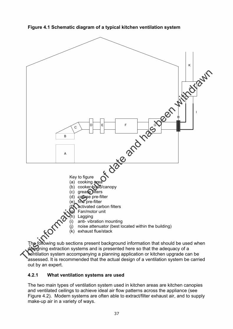
Figure 4.1 Schematic diagram of a typical kitchen ventilation system
Key to figure (a) cooking area (b) cooker hood/canopy (c) grease filters (d) coarse pre-filter (e) fine pre-filter (f) activated carbon filters (g) Fan/motor unit (h) Lagging (i) anti- vibration mounting (j) noise attenuator (best located within the building) (k) exhaust flue/stack
The following sub sections present background information that should be used when designing extraction systems and is presented here so that the adequacy of a ventilation system accompanying a planning application or kitchen upgrade can be assessed. It is recommended that the actual design of a ventilation system be carried out by an expert.
4.2.1 What ventilation systems are used
The two main types of ventilation system used in kitchen areas are kitchen canopies and ventilated ceilings to achieve ideal air flow patterns across the appliance (see Figure 4.2). Modern systems are often able to extract/filter exhaust air, and to supply make-up air in a variety of ways.
A
B
CF GED
HI
J
K
This in
formati
on is
out o
f date
and h
as be
en w
ithdra
wn
38
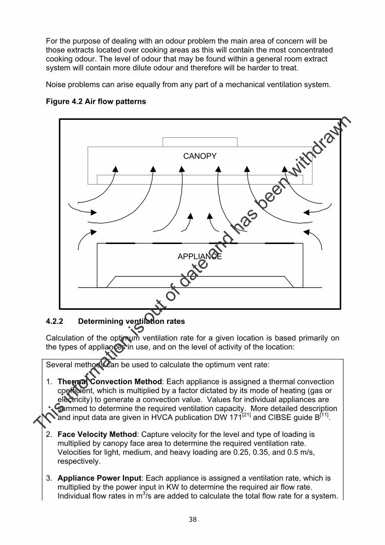
For the purpose of dealing with an odour problem the main area of concern will be those extracts located over cooking areas as this will contain the most concentrated cooking odour. The level of odour that may be found within a general room extract system will contain more dilute odour and therefore will be harder to treat.
Noise problems can arise equally from any part of a mechanical ventilation system.
Figure 4.2 Air flow patterns
4.2.2 Determining ventilation rates
Calculation of the optimum ventilation rate for a given location is based primarily on the types of appliances in use, and on the level of activity of the location:
Several methods can be used to calculate the optimum vent rate:
1. Thermal Convection Method: Each appliance is assigned a thermal convection coefficient, which is multiplied by a factor dictated by its mode of heating (gas or electricity) to generate a convection value. Values for individual appliances are summed to determine the required ventilation capacity. More detailed description and input data are given in HVCA publication DW 171[21] and CIBSE guide B[11].
2. Face Velocity Method: Capture velocity for the level and type of loading is multiplied by canopy face area to determine the required ventilation rate. Velocities for light, medium, and heavy loading are 0.25, 0.35, and 0.5 m/s, respectively.
3. Appliance Power Input: Each appliance is assigned a ventilation rate, which is multiplied by the power input in KW to determine the required air flow rate. Individual flow rates in m3/s are added to calculate the total flow rate for a system.
APPLIANCE
CANOPY
This in
formati
on is
out o
f date
and h
as be
en w
ithdra
wn
39
More detailed description and input data are given in HVCA publication DW 171[21] and CIBSE guide B[11].
4. Air Changes Method: A per hour vent rate equivalent to 40 times the ventilation volume is considered minimum for comfort under normal conditions, but rates as high as 60-100 volumes per hour may be required where high-output equipment is densely located. Using this method air will may be extracted via both a hood extract and a ceiling extract.
5. Linear Extract Method: Each linear meter of active filter length is assigned a vent rate depending on the vent canopy type.
6. Meals Method: Extract rate in litres/sec is expressed as 10-15 times the number of meals served per hour.
7. Area Method: Area of the cooking space in m2 is multiplied by 15-20 litres/sec to give an approximate volume flow rate.
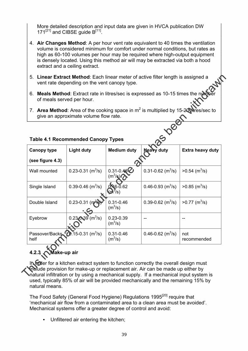
Table 4.1 Recommended Canopy Types
Canopy type
(see figure 4.3)
Light duty Medium duty Heavy duty Extra heavy duty
Wall mounted 0.23-0.31 (m3/s) 0.31-0.46 (m3/s)
0.31-0.62 (m3/s) >0.54 (m3/s)
Single Island 0.39-0.46 (m3/s) 0.46-0.62 (m3/s)
0.46-0.93 (m3/s) >0.85 (m3/s)
Double Island 0.23-0.31 (m3/s) 0.31-0.46 (m3/s)
0.39-0.62 (m3/s) >0.77 (m3/s)
Eyebrow 0.23-0.39 (m3/s) 0.23-0.39 (m3/s)
-- --
Passover/Backshelf
0.15-0.31 (m3/s) 0.31-0.46 (m3/s)
0.46-0.62 (m3/s) not recommended
4.2.3 Make-up air
In order for a kitchen extract system to function correctly the overall design must include provision for make-up or replacement air. Air can be made up either by natural infiltration or by using a mechanical supply. If a mechanical input system is used, typically 85% of air will be provided mechanically and the remaining 15% by natural means.
The Food Safety (General Food Hygiene) Regulations 1995[20] require that ‘mechanical air flow from a contaminated area to a clean area must be avoided’. Mechanical systems offer a greater degree of control and avoid:
• Unfiltered air entering the kitchen;
This in
formati
on is
out o
f date
and h
as be
en w
ithdra
wn
40
• Air being drawn from dirty areas; and
• Draughts and discomfort during cold weather
Natural systems cannot provide targeted ‘cooling’ to staff working adjacent to canopies. Make-up air can be introduced into a kitchen by means of:
• the canopy;
• ventilated ceiling;
• HVAC system; or
• combination of the above.
A range of extraction/make up air hoods are available. The choice of hood will be dictated by the application. Whichever system is chosen due regard should be given to potential noise issues arising from the make up air system (fans, duct work, grilles, noise breakout etc).
Where a kitchen relies on a natural make-up air system, its resistance must be taken into account when calculating the overall system resistance against which the extraction fan will operate. In such a system, restaurant operators may rely on open doors and windows within the kitchen area to supply natural make up air. During summer months this may give rise to odour and noise problems for receptors living adjacent to the kitchen area or, allow the ingress of pests into the food areas.
This in
formati
on is
out o
f date
and h
as be
en w
ithdra
wn
41
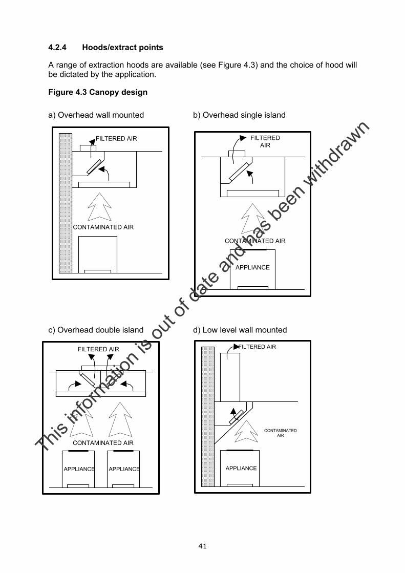
4.2.4 Hoods/extract points
A range of extraction hoods are available (see Figure 4.3) and the choice of hood will be dictated by the application.
Figure 4.3 Canopy design a) Overhead wall mounted b) Overhead single island
c) Overhead double island d) Low level wall mounted
CONTAMINATED AIR
FILTERED AIR
APPLIANCE APPLIANCE
FILTEREDAIR
CONTAMINATED AIR
APPLIANCE
CONTAMINATED AIR
FILTERED AIR
FILTERED AIR
CONTAMINATEDAIR
APPLIANCE
This in
formati
on is
out o
f date
and h
as be
en w
ithdra
wn
42
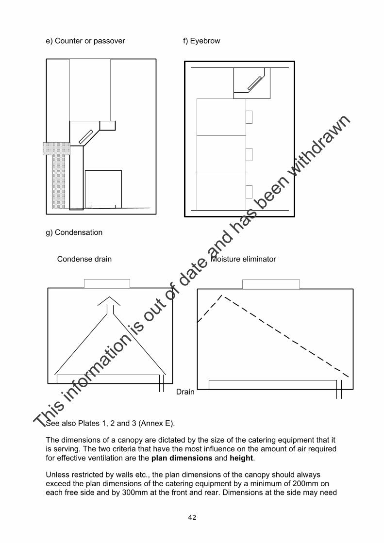
e) Counter or passover f) Eyebrow
g) Condensation
Condense drain Moisture eliminator
See also Plates 1, 2 and 3 (Annex E).
The dimensions of a canopy are dictated by the size of the catering equipment that it is serving. The two criteria that have the most influence on the amount of air required for effective ventilation are the plan dimensions and height.
Unless restricted by walls etc., the plan dimensions of the canopy should always exceed the plan dimensions of the catering equipment by a minimum of 200mm on each free side and by 300mm at the front and rear. Dimensions at the side may need
Drain
This in
formati
on is
out o
f date
and h
as be
en w
ithdra
wn

43
to be increased where high output equipment is located at the end of the cooking line-up.
Where combination steamer and certain types of baking ovens are used, the overhang at the front should be 600mm to cope with steam or fumes that arise when the doors of the appliance are opened.
The height of the canopy is governed by the height of the ceiling and the underside of the canopy should be located between 2000 and 2100 mm above the finished floor level. The efficiency of canopies less than 400mm high are less than normal because the collection volume is reduced. In these situations, the face velocity may need to be increased to 0.5m/s to compensate. Where the ideal flow rate cannot be achieved the size of the canopy may be increased to aid capture.
The ideal distance between the lowest edge of the grease filter and the top of the cooking surface should be between 450mm to 1350mm. This is to avoid the risk of excessive temperatures or fire in the filter that could cause the extracted grease to vaporise and pass through to the ductwork. This dimension will vary with the type of cooking appliance and can be reduced where fire suppression equipment is installed, but should never be below 1350mm where mesh filters are installed. Figure 4.4 demonstrates required canopy dimensions.
Figure 4.4 Canopy dimensions
4.2.5 Ventilated ceilings
In certain circumstances it may not be practical to install extract canopies, for example:
• where due to structural limitations, low ceiling levels make the use of canopies impractical;
2000to
2100
Min 400
50Min 250
Filter
CONTAMINATED AIR
FILTERED AIR
This in
formati
on is
out o
f date
and h
as be
en w
ithdra
wn
44
• where the cooking equipment does not generate intensive output in concentrated areas; or
• where a good level of extraction is required but the level of odour/grease produced is relatively low such as in large food preparation or distribution areas.
In these situations ventilated ceilings may be employed. These systems tend to have higher capital and installation costs and therefore the use will be limited to larger kitchens.
This in
formati
on is
out o
f date
and h
as be
en w
ithdra
wn
45
Two types of system are available:
• Cassette system: Is an integrated system incorporating partitioned or dedicated extract and partitioned or dedicated supply. The systems are modular and contain a number of cassettes of proprietary design, which filter and separate grease from the air prior to its exhaust. The grease is normally collected in a non-drip integral or perimeter trough for removal and cleaning.
• Modular plenum system: The plenum system comprises a series of filter plenum units which allow the exhaust air to pass through a single or double bank grease filter for grease separation before passing into the ceiling void for central point connection and discharge to atmosphere.
4.2.6 Materials of construction of canopies
The Food Safety (General Food Hygiene) Regulations[20] requires that in food preparation areas:
‘ceilings and overhead fixtures must be designed, constructed and finished to prevent the accumulation of dirt and reduce condensation, the growth of undesirable moulds and the shedding of particles.’
In relation to canopies, it is best practice to use stainless steel especially if the relevant surface comes directly into contact with food. Typically canopies and other overhead fixtures are fabricated using ultra fine-grained stainless steel (Grade 304). Higher Grades of stainless steel may also be specified. Other materials that could be employed are as follows:
• Galvanised steel is not recommended.
• Untreated aluminium should not be used. Poisonous particles can be generated when aluminium oxidises in moist atmospheres.
• Electrolytic zinc coated steel can be used provided it is treated with a protective finish (e.g. heat baked epoxy polyester powder coating).
• Wired glass and translucent panels should not be used as bacterial growth can occur at joints between sheets.
Other best practice guidelines include:
• Where air must be equalised within a supply plenum of a canopy 0.8 mm perforated stainless steel sheet should be used. In addition, care should be taken to ensure that the face velocity is about 0.7 m/s. Noise generation increases when velocities of 0.9 m/s are exceeded.
• Discharge grills on make-up air system should be fabricated with 1mm perforated stainless steel sheet.
• Condensation should be avoided in canopies that are provided with supply plenum. Where insulation is used it should:
This in
formati
on is
out o
f date
and h
as be
en w
ithdra
wn
46
• be a rigid foil faced non fibrous slab, with a class 1 spread of flame; and
• not be fibre based as this could contaminate food.
4.3 Duct work
Duct work on a kitchen ventilation system may include:
• straight ducts of various length, rectangular or circular in cross-section;
• silencers;
• bends (elbows), right angled or curved;
• branches, which may have one or more outlets;
• distribution boxes (plenums);
• terminal units, grilles, diffusers, registers; and
• transition pieces which connect the fan or silencer to the duct.
Ductwork delivering make-up air to the canopy have no special requirements, other than the application of thermal insulation and protective mesh (pre-filtration and bird mesh screen). Designs should ensure that mechanical air flow from a contaminated area into a clean area must be avoided. Under normal circumstances and providing it runs within the fire compartment of the kitchen itself, extraction duct work has no special requirements. Such ductwork should be low pressure Class A type.
Other design considerations are:
• For kitchens, cooking materials with high grease content total ‘grease tightness’ may be required. This duct work may be constructed from 1.2 mm stainless steel or 1.6 mm electrolytic zinc coated steel. The duct work should be fully welded. Where gaskets are required they should be non-porous, impervious to grease and cooking oils and withstand temperatures experienced within the extract hood.
• For duct work serving water wash or water mist filtration systems should slope back to the canopy with a gradient of 1 in 50.
• Wherever possible duct work should not pass through any fire barriers.
• Duct work should take the most direct route to the exterior of the building with the minimum number of changes in direction and possible grease traps.
• No other systems should be connected into the kitchen extract system.
• Where the captured air cannot be discharge immediately fire rated ductwork may be required.
• Where supply air discharges directly into or downwards across the face of the canopy fire dampers should be installed in the supply spigot and where the
This in
formati
on is
out o
f date
and h
as be
en w
ithdra
wn
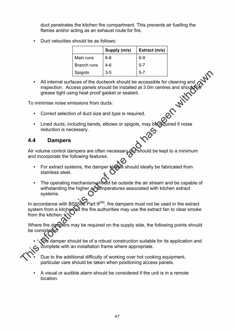
47
duct penetrates the kitchen fire compartment. This prevents air fuelling the flames and/or acting as an exhaust route for fire.
• Duct velocities should be as follows:
Supply (m/s) Extract (m/s)
Main runs
Branch runs
Spigots
6-8
4-6
3-5
6-9
5-7
5-7
• All internal surfaces of the ductwork should be accessible for cleaning and inspection. Access panels should be installed at 3.0m centres and should be grease tight using heat proof gasket or sealant.
To minimise noise emissions from ducts:
• Correct selection of duct size and type is required.
• Lined ducts, including bends, elbows or spigots, may be required if noise reduction is necessary.
4.4 Dampers
Air volume control dampers are often necessary but should be kept to a minimum and incorporate the following features:
• For extract systems, the damper blades should ideally be fabricated from stainless steel.
• The operating mechanism should be outside the air stream and be capable of withstanding the higher air temperatures associated with kitchen extract systems.
In accordance with BS5588 Part 9[26], fire dampers must not be used in the extract system from a kitchen as the fire authorities may use the extract fan to clear smoke from the kitchen.
Where fire dampers may be required on the supply side, the following points should be considered:
• The damper should be of a robust construction suitable for its application and complete with an installation frame where appropriate.
• Due to the additional difficulty of working over hot cooking equipment, particular care should be taken when positioning access panels.
• A visual or audible alarm should be considered if the unit is in a remote location.
This in
formati
on is
out o
f date
and h
as be
en w
ithdra
wn
48
4.5 Fans
Kitchen ventilation systems often have relatively high resistance against which a fan has to operate. Therefore, fans need to be sized to cope with a design pressure of a minimum additional 10% pressure margin. Care must to be taken:
• to ensure operational changes e.g. build up of dirt on mesh filters are taken into account; and
• if changes are made to the ventilation system that may alter the operating pressure.
To overcome such changes variable speed control or balancing dampers may be used. A range of impeller designs is available as follows:
• Backward curved centrifugal, mixed flow or axial flow impellers are preferred as they are less prone to imbalance and are easier to clean and maintain due to their open construction.
• Fixed or adjustable metal impellers are recommended.
• Lightweight multi-vane or plastic–type impellers can warp and are prone to collecting grease. Although plastic bladed fans can be used in non-grease, low temperature situation.
The fan must be able to operate at between 40o and 60o at 95% relative humidity. Motors should be rated to IP55. Where fan motors sit within warm moist air streams, they should be upgraded to withstand more onerous conditions. To avoid excessive temperature build-up, temperature detectors should be fitted.
Drain holes should be provided at the lowest point in the fan housing to remove condensation. Care needs to be taken to ensure that the drain hole does not downgrade the Index of Protection (IP) of the motor.
Dual or variable speed regulation are widely used. The fan must always operate at its design duty, especially when grease is being produced. A minimum extract level should be set within the speed regulator to ensure that, even at low speed, an adequate rate of ventilation is maintained. Speed regulation should be applied to both make-up air and extraction air. Speed regulation cannot be employed with water wash/cartridge systems as flow rates are fixed.
Make-up and extract fan operation should be interlocked with gas supply, so that gas supply is switched off if the fans fail. Fans should be isolated when fire a suppression system is activated.
The connection between ductwork and fan housing should be suitable for use in grease-laden atmospheres and at duct temperature. Joints must be clamped or bonded to prevent air leakage. Under fire conditions the material should have a minimum integrity of at least 15 minutes. The advantages and disadvantages of different fan types are summarised in Table 4.2.
This in
formati
on is
out o
f date
and h
as be
en w
ithdra
wn
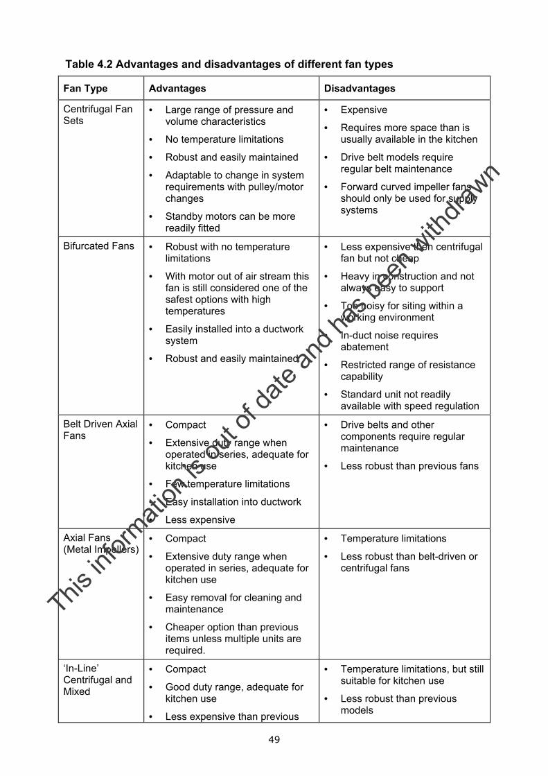
49
Table 4.2 Advantages and disadvantages of different fan types
Fan Type Advantages Disadvantages
Centrifugal Fan Sets
• Large range of pressure and volume characteristics
• No temperature limitations
• Robust and easily maintained
• Adaptable to change in system requirements with pulley/motor changes
• Standby motors can be more readily fitted
• Expensive
• Requires more space than is usually available in the kitchen
• Drive belt models require regular belt maintenance
• Forward curved impeller fans should only be used for supply systems
Bifurcated Fans • Robust with no temperature limitations
• With motor out of air stream this fan is still considered one of the safest options with high temperatures
• Easily installed into a ductwork system
• Robust and easily maintained
• Less expensive then centrifugal fan but not cheap
• Heavy in construction and not always easy to support
• Too noisy for siting within a working environment
• In-duct noise requires abatement
• Restricted range of resistance capability
• Standard unit not readily available with speed regulation
Belt Driven Axial Fans
• Compact
• Extensive duty range when operated in series, adequate for kitchen use
• Few temperature limitations
• Easy installation into ductwork
• Less expensive
• Drive belts and other components require regular maintenance
• Less robust than previous fans
Axial Fans (Metal Impellers)
• Compact
• Extensive duty range when operated in series, adequate for kitchen use
• Easy removal for cleaning and maintenance
• Cheaper option than previous items unless multiple units are required.
• Temperature limitations
• Less robust than belt-driven or centrifugal fans
‘In-Line’ Centrifugal and Mixed
• Compact
• Good duty range, adequate for kitchen use
• Less expensive than previous
• Temperature limitations, but still suitable for kitchen use
• Less robust than previous models
This in
formati
on is
out o
f date
and h
as be
en w
ithdra
wn
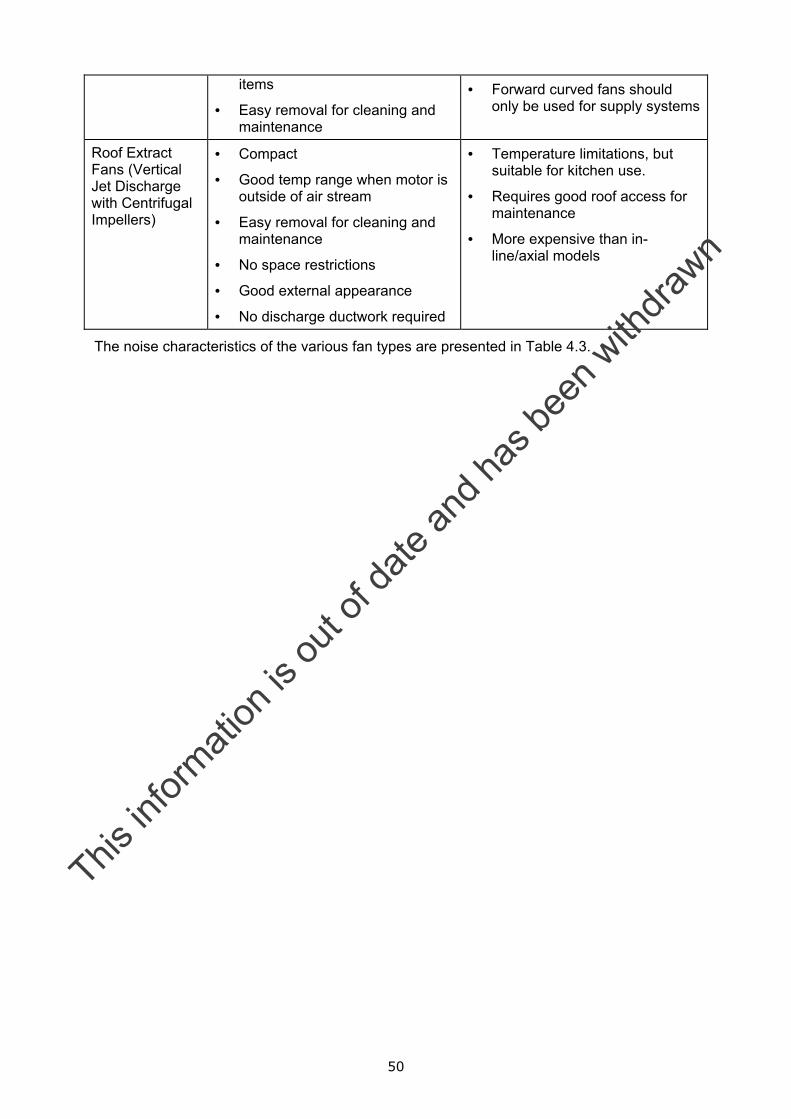
50
items
• Easy removal for cleaning and maintenance
• Forward curved fans should only be used for supply systems
Roof Extract Fans (Vertical Jet Discharge with Centrifugal Impellers)
• Compact
• Good temp range when motor is outside of air stream
• Easy removal for cleaning and maintenance
• No space restrictions
• Good external appearance
• No discharge ductwork required
• Temperature limitations, but suitable for kitchen use.
• Requires good roof access for maintenance
• More expensive than in-line/axial models
The noise characteristics of the various fan types are presented in Table 4.3.
This in
formati
on is
out o
f date
and h
as be
en w
ithdra
wn
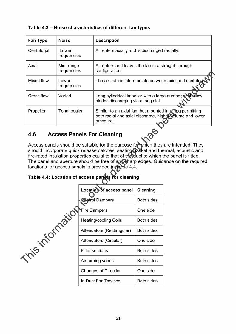
51
Table 4.3 – Noise characteristics of different fan types
Fan Type Noise Description
Centrifugal Lower frequencies
Air enters axially and is discharged radially.
Axial Mid–range frequencies
Air enters and leaves the fan in a straight–through configuration.
Mixed flow Lower frequencies
The air path is intermediate between axial and centrifugal.
Cross flow Varied Long cylindrical impeller with a large number of shallow blades discharging via a long slot.
Propeller Tonal peaks Similar to an axial fan, but mounted in a ring permitting both radial and axial discharge, higher volume and lower pressure.
4.6 Access Panels For Cleaning
Access panels should be suitable for the purpose for which they are intended. They should incorporate quick release catches, sealing gasket and thermal, acoustic and fire-rated insulation properties equal to that of the duct to which the panel is fitted. The panel and aperture should be free of any sharp edges. Guidance on the required locations for access panels is provided in Table 4.4.
Table 4.4: Location of access panels for cleaning
Location of access panel Cleaning
Control Dampers Both sides
Fire Dampers One side
Heating/cooling Coils Both sides
Attenuators (Rectangular) Both sides
Attenuators (Circular) One side
Filter sections Both sides
Air turning vanes Both sides
Changes of Direction One side
In Duct Fan/Devices Both sides
This in
formati
on is
out o
f date
and h
as be
en w
ithdra
wn
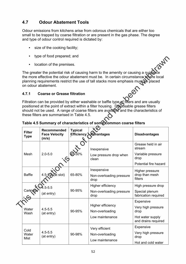
52
4.7 Odour Abatement Tools
Odour emissions from kitchens arise from odorous chemicals that are either too small to be trapped by coarse filtration or are present in the gas phase. The degree and type of odour control required is dictated by:
• size of the cooking facility;
• type of food prepared; and
• location of the premises.
The greater the potential risk of causing harm to the amenity or causing a nuisance the more effective the odour abatement must be. In certain circumstance where local planning requirements restrict the use of tall stacks more emphasis must be placed on odour abatement.
4.7.1 Coarse or Grease filtration
Filtration can be provided by either washable or baffle type of filters and are usually positioned at the point of extract within a filter housing. Disposable grease filters should not be used. A range of coarse filters are available and the characteristics of these filters are summarised in Table 4.5.
Table 4.5 Summary of characteristics of some common coarse filters
Filter Type
Recommended Face Velocity (m/s)
Typical Efficiency*
Advantages Disadvantages
Mesh 2.0-5.0 40-50% Inexpensive
Low pressure drop when clean
Grease held in air stream
Variable pressure drop
Potential fire hazard
Baffle 4.5-5.5 (at slot) 65-80% Inexpensive
Non-overloading pressure drop
Higher pressure drop than mesh filters
Cartridge 4.5-5.5
(at entry) 90-95%
Higher efficiency
Non-overloading pressure drop
High pressure drop
Special plenum fabrication required
Water Wash
4.5-5.5 (at entry) 90-95%
Higher efficiency
Non-overloading
Low maintenance
Expensive
Very high pressure drop
Hot water supply and drains required
Cold Water Mist
4.5-5.5 (at entry) 90-98%
Very efficient
Non-overloading
Low maintenance
Expensive
Very high pressure drop
Hot and cold water
This in
formati
on is
out o
f date
and h
as be
en w
ithdra
wn
53
supplies and drains required
*manufacturer’s data.
Mesh or impingement filters
These filters comprise a number of layers of galvanised or stainless steel mesh within a steel housing. Grease laden air is deposited onto the non-corrosive mesh. Their application is limited to low level grease production. A mesh of less than 50 mm is unlikely to be effective. The performance varies with use and temperature and may need to be cleaned twice weekly to avoid grease build-up. Mesh filters provide no barrier to flame and therefore should not be used either at low level or in applications where there is a risk of fire. A mesh filter should be installed at an angle of not less than 45o from the horizontal. Plate 4 (Annex E) shows an example of a mesh filter.
This in
formati
on is
out o
f date
and h
as be
en w
ithdra
wn
54
Baffle filters
These filters comprise a number of interlocked vanes which when assembled, form a two-pass grease removal device. Grease laden air passes through the filter and by a series of forced changes in direction and velocity, the grease becomes separated from the air stream and is deposited on the vertical vanes. The deposited grease is then drained off through weep holes spaced at intervals and into a collection drawer that has to be cleaned at regular intervals. The size of the grease drawer should be sufficient to suit the type of cooking and frequency of cleaning. The grease drawer must be isolated from the air stream otherwise re-entrainment can occur.
The resistance to air flow in a baffle filter is higher than with mesh filters, but pressure drop remains constant and blades provide a barrier in the event of a flash fire. A baffle filter should be installed at an angle of not less than 45o from the horizontal.
Cartridge filters
Installed horizontally, cartridge filters comprise a high velocity slot opening on to a series of baffles which cause air to change direction four times compared to only twice in a conventional baffle filter. The cartridge filters are installed over the full length of the extract plenum and should be sloped to allow trapped grease to fall through a drain to a grease drawer. These filters are intended for heavy grease loads. Having a higher velocity enables lower air volumes to be used. Air balancing is required to prevent carry over of grease.
Water wash systems
These systems comprise an extract plenum similar to the cartridge filters, except that there is an inbuilt self-cleaning system. This provides routine maintenance as well as fire protection to the plenum and duct. A water wash canopy is operated by a control panel. In its simplest form it is started and stopped at the beginning and end of the cooking process each day. Automatic systems are available. Cleaning is achieved by spraying the interior of the canopy extraction system chamber with pressurised hot water containing detergent. The waste water flows from the system to drain.
Continuous cold water mist systems
These systems are similar to water wash system in which grease extraction is enhanced by means of a cold water spray that runs continuously during cooking operation. The vapour entering the canopy passes through the mist, which causes the grease particles in the suspension to drop in temperature, solidify, increase in size, and drop via a drain trough to a drain. These systems are particularly suitable for solid fuel appliances where the mist will extinguish hot embers that may be drawn into the canopy. The cleaning regime is the same as for a water wash system.
4.7.2 Fine filtration
A basic filtration system can be used to deal with a low intensity odour problem, but more usually will form a protective pre-treatment step before an activated carbon step.
A typical filtration system may be supplied with a three stages of progressively more efficient filtration. This would include:
This in
formati
on is
out o
f date
and h
as be
en w
ithdra
wn
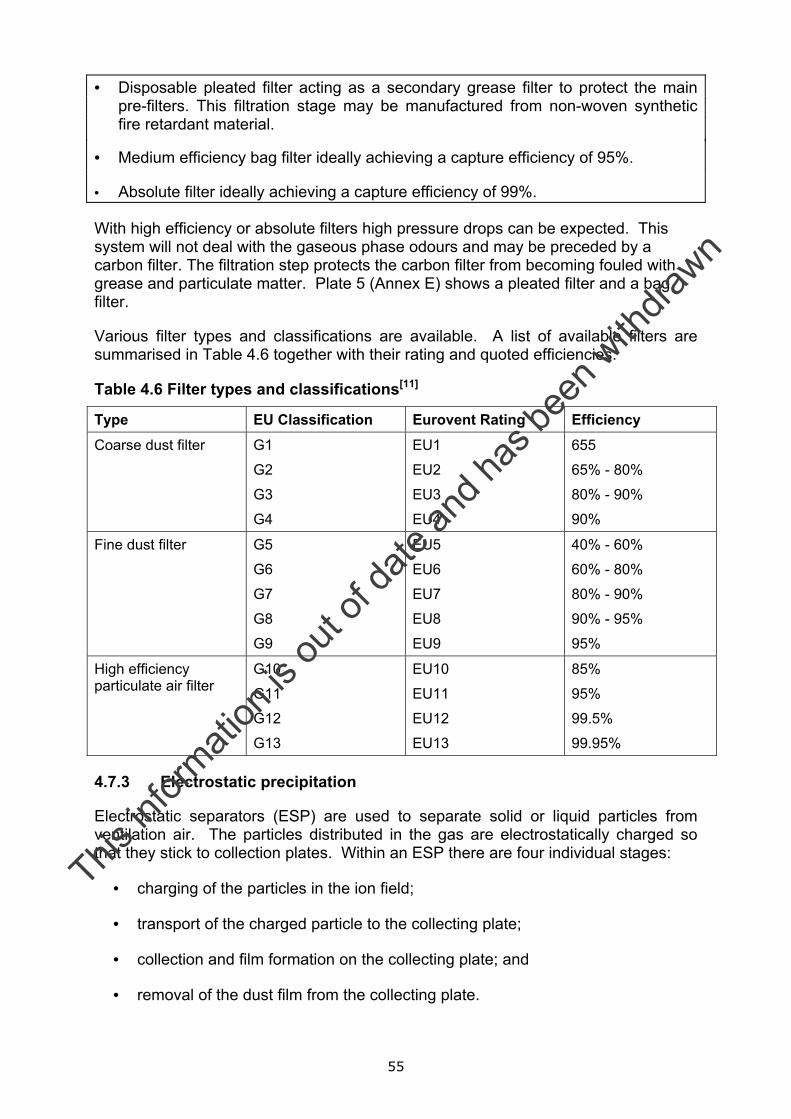
55
• Disposable pleated filter acting as a secondary grease filter to protect the main pre-filters. This filtration stage may be manufactured from non-woven synthetic fire retardant material.
• Medium efficiency bag filter ideally achieving a capture efficiency of 95%.
• Absolute filter ideally achieving a capture efficiency of 99%.
With high efficiency or absolute filters high pressure drops can be expected. This system will not deal with the gaseous phase odours and may be preceded by a carbon filter. The filtration step protects the carbon filter from becoming fouled with grease and particulate matter. Plate 5 (Annex E) shows a pleated filter and a bag filter.
Various filter types and classifications are available. A list of available filters are summarised in Table 4.6 together with their rating and quoted efficiencies.
Table 4.6 Filter types and classifications[11]
Type EU Classification Eurovent Rating Efficiency Coarse dust filter G1
G2
G3
G4
EU1
EU2
EU3
EU4
655
65% - 80%
80% - 90%
90%
Fine dust filter G5
G6
G7
G8
G9
EU5
EU6
EU7
EU8
EU9
40% - 60%
60% - 80%
80% - 90%
90% - 95%
95%
High efficiency particulate air filter
G10
G11
G12
G13
EU10
EU11
EU12
EU13
85%
95%
99.5%
99.95%
4.7.3 Electrostatic precipitation
Electrostatic separators (ESP) are used to separate solid or liquid particles from ventilation air. The particles distributed in the gas are electrostatically charged so that they stick to collection plates. Within an ESP there are four individual stages:
• charging of the particles in the ion field;
• transport of the charged particle to the collecting plate;
• collection and film formation on the collecting plate; and
• removal of the dust film from the collecting plate.
This in
formati
on is
out o
f date
and h
as be
en w
ithdra
wn
56
The main components of an ESP are the filter housing, discharge and collecting electrodes, power supply, gas guides or baffles and a rapping system for cleaning the collecting plates.
ESPs can be designed to eliminate extensive quantities of smoke, giving collection efficiencies of 99% at 1 µm and 90% at 0.1 µm. The effectiveness of an ESP is limited to removing the grease that adheres to smoke and should not be considered to be a primary source of odour control. Where installed, pre-filters should be fitted upstream of the ESP to provide some protection from large contaminants that may pass through the grease filters. The types of ESP that are used to treat kitchen ventilation emissions are less effective at temperatures over 60oC and are not suitable for relative humidity levels of above 75%.
Where an ESP is used to treat oily fume the collecting plates can become fouled, rendering them less effective. Weekly servicing should be the minimum requirement and they should be cleaned immediately as soon as there is any sign of deterioration in fume control. Some manufacturers have incorporated automatic self-cleaning mechanism into their equipment to facilitate automatic daily cleaning. Plates 6 and 7 (Annex E) provide examples of an electrostatic precipitator.
4.7.4 Adsorption
Adsorption is a process involving the capture of airborne components on to a fine particulate active surface. There are a number of possible active materials that can be used for general application but activated carbon is by far the most widely used. Other materials used are: Zeolites, silicas and polymeric resins. Activated carbon systems are available that include impregnated oxidising materials e.g. chlorine dioxide or permanganate, although such materials tend to be more expensive.
Adsorption is a dynamic process in which gaseous molecules impinge on the surface of the solid and remain there for a period of time before desorbing again in to the gas phase. An equilibrium is established between the adsorption and desorption processes. For the majority of odorous emissions, where the organic mass emission is low, the equilibrium amount of adsorbed material increases rapidly with small increases in concentration. Thus, the adsorption process allows a positive driving force for adsorption up to a point where the equilibrium position changes and the odour concentration in the outlet exhaust increases. This is the point at which the carbon has been fully utilised and there are insufficient active sites remaining for further adsorption. The adsorption bed has thus reached the end of its useful life and will require replacement or regeneration.
The adsorption process, ensuring odorous components adhere to the matrix, can be physical e.g. adsorbed molecules are held to the surface by Van der Waals forces, or chemical e.g. a chemical bond forms between the adsorbed molecules and the surface. Adsorption, using carbon as a matrix, can be a very effective abatement option, with odour removal efficiencies in the range 80 to 99% achievable.
Design considerations for adsorption systems include:
• Residence time typically of between 0.1 to 0.2 seconds for gas streams containing relatively low concentration of odorants (this can rise to 1 to 3 seconds for gas streams containing relatively high concentration of odorants).
This in
formati
on is
out o
f date
and h
as be
en w
ithdra
wn
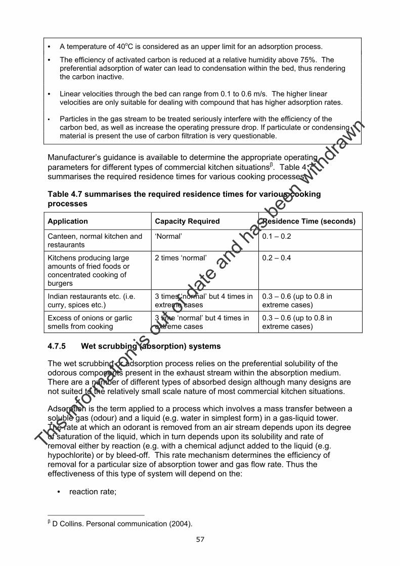
57
• A temperature of 40oC is considered as an upper limit for an adsorption process.
• The efficiency of activated carbon is reduced at a relative humidity above 75%. The preferential adsorption of water can lead to condensation within the bed, thus rendering the carbon inactive.
• Linear velocities through the bed can range from 0.1 to 0.6 m/s. The higher linear velocities are only suitable for dealing with compound that has higher adsorption rates.
• Particles in the gas stream to be treated seriously interfere with the efficiency of the carbon bed, as well as increase the operating pressure drop. If particulate or condensing material is present the use of carbon filtration is very questionable.
Manufacturer’s guidance is available to determine the appropriate operating parameters for different types of commercial kitchen situationsβ. Table 4.7 summarises the required residence times for various cooking processes.
Table 4.7 summarises the required residence times for various cooking processes
Application Capacity Required Residence Time (seconds)
Canteen, normal kitchen and restaurants
‘Normal’ 0.1 – 0.2
Kitchens producing large amounts of fried foods or concentrated cooking of burgers
2 times ‘normal’ 0.2 – 0.4
Indian restaurants etc. (i.e. curry, spices etc.)
3 times ‘normal’ but 4 times in extreme cases
0.3 – 0.6 (up to 0.8 in extreme cases)
Excess of onions or garlic smells from cooking
3 time ‘normal’ but 4 times in extreme cases
0.3 – 0.6 (up to 0.8 in extreme cases)
4.7.5 Wet scrubbing (absorption) systems
The wet scrubbing or adsorption process relies on the preferential solubility of the odorous components present in the exhaust stream within the absorption medium. There are a number of different types of absorbed design although many designs are not suited to the relatively small scale nature of most commercial kitchen situations.
Adsorption is the term applied to a process which involves a mass transfer between a soluble gas (odour) and a liquid (e.g. water in simplest form) in a gas-liquid tower. The rate at which an odorant is removed from an air stream depends upon its degree of saturation of the liquid, which in turn depends upon its solubility and rate of removal either by reaction (e.g. with a chemical adjunct added to the liquid (e.g. hypochlorite) or by bleed-off. This rate mechanism determines the efficiency of removal for a particular size of absorption tower and gas flow rate. Thus the effectiveness of this type of system will depend on the:
• reaction rate;
β D Collins. Personal communication (2004).
This in
formati
on is
out o
f date
and h
as be
en w
ithdra
wn
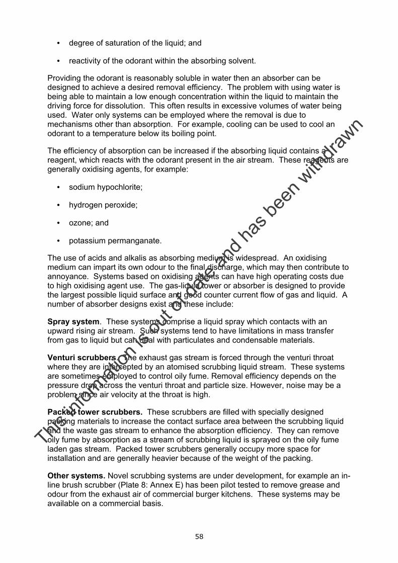
58
• degree of saturation of the liquid; and
• reactivity of the odorant within the absorbing solvent.
Providing the odorant is reasonably soluble in water then an absorber can be designed to achieve a desired removal efficiency. The problem with using water is being able to maintain a low enough concentration within the liquid to maintain the driving force for dissolution. This often results in excessive volumes of water being used. Water only systems can be employed where the removal is due to mechanisms other than absorption. For example, cooling can be used to cool an odorant to a temperature below its boiling point.
The efficiency of absorption can be increased if the absorbing liquid contains a reagent, which reacts with the odorant present in the air stream. These reagents are generally oxidising agents, for example:
• sodium hypochlorite;
• hydrogen peroxide;
• ozone; and
• potassium permanganate.
The use of acids and alkalis as absorbing medium is widespread. An oxidising medium can impart its own odour to the final discharge, which may then contribute to annoyance. Systems based on oxidising agents can have high operating costs due to high oxidising agent use. The gas-liquid tower or absorber is designed to provide the largest possible liquid surface and good counter current flow of gas and liquid. A number of absorber designs exist and these include:
Spray system. These systems comprise a liquid spray which contacts with an upward rising air stream. Such systems tend to have limitations in mass transfer from gas to liquid but can deal with particulates and condensable materials.
Venturi scrubbers. The exhaust gas stream is forced through the venturi throat where they are intercepted by an atomised scrubbing liquid stream. These systems are sometimes employed to control oily fume. Removal efficiency depends on the pressure drop across the venturi throat and particle size. However, noise may be a problem since air velocity at the throat is high.
Packed tower scrubbers. These scrubbers are filled with specially designed packing materials to increase the contact surface area between the scrubbing liquid and the waste gas stream to enhance the absorption efficiency. They can remove oily fume by absorption as a stream of scrubbing liquid is sprayed on the oily fume laden gas stream. Packed tower scrubbers generally occupy more space for installation and are generally heavier because of the weight of the packing.
Other systems. Novel scrubbing systems are under development, for example an in-line brush scrubber (Plate 8: Annex E) has been pilot tested to remove grease and odour from the exhaust air of commercial burger kitchens. These systems may be available on a commercial basis.
This in
formati
on is
out o
f date
and h
as be
en w
ithdra
wn
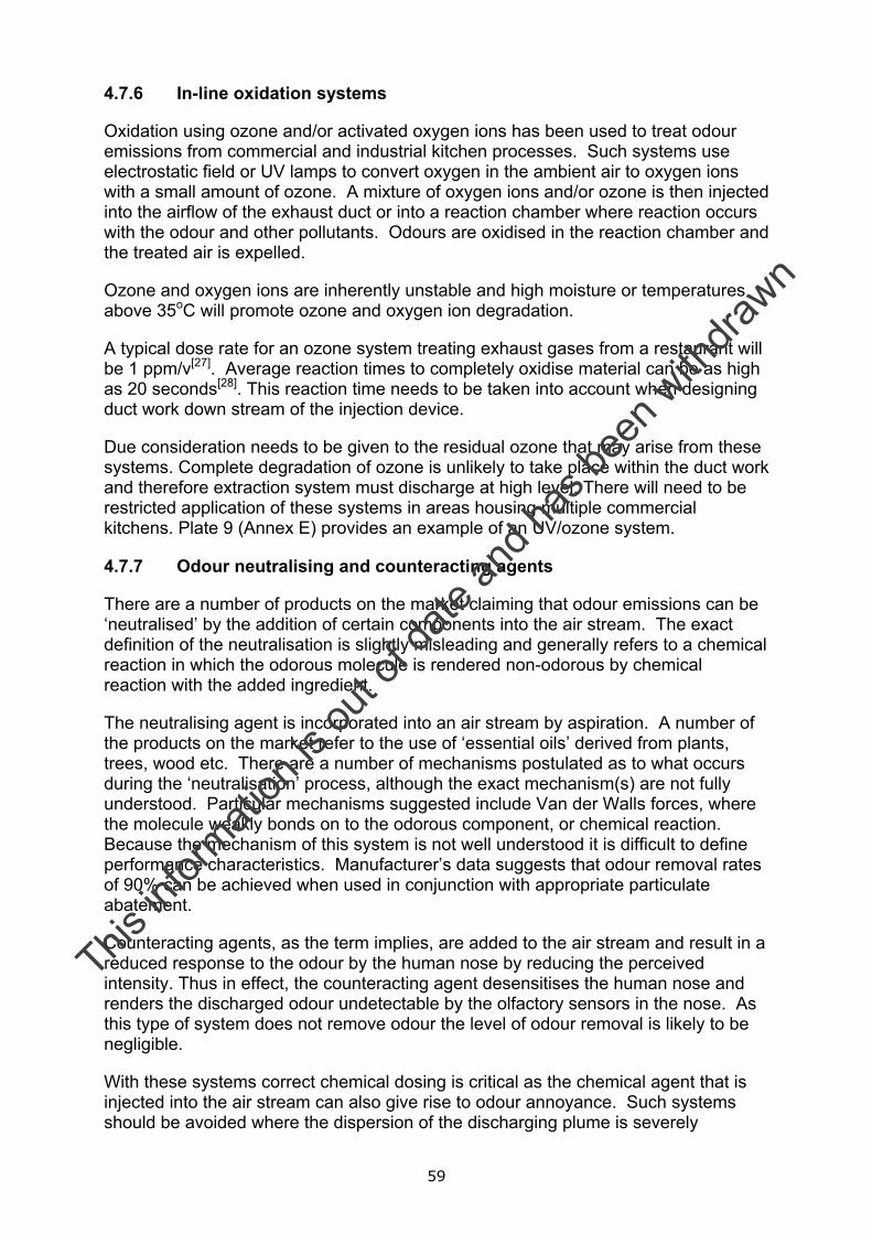
59
4.7.6 In-line oxidation systems
Oxidation using ozone and/or activated oxygen ions has been used to treat odour emissions from commercial and industrial kitchen processes. Such systems use electrostatic field or UV lamps to convert oxygen in the ambient air to oxygen ions with a small amount of ozone. A mixture of oxygen ions and/or ozone is then injected into the airflow of the exhaust duct or into a reaction chamber where reaction occurs with the odour and other pollutants. Odours are oxidised in the reaction chamber and the treated air is expelled.
Ozone and oxygen ions are inherently unstable and high moisture or temperatures above 35oC will promote ozone and oxygen ion degradation.
A typical dose rate for an ozone system treating exhaust gases from a restaurant will be 1 ppm/v[27]. Average reaction times to completely oxidise material can be as high as 20 seconds[28]. This reaction time needs to be taken into account when designing duct work down stream of the injection device.
Due consideration needs to be given to the residual ozone that may arise from these systems. Complete degradation of ozone is unlikely to take place within the duct work and therefore extraction system must discharge at high level. There will need to be restricted application of these systems in areas housing multiple commercial kitchens. Plate 9 (Annex E) provides an example of an UV/ozone system.
4.7.7 Odour neutralising and counteracting agents
There are a number of products on the market claiming that odour emissions can be ‘neutralised’ by the addition of certain components into the air stream. The exact definition of the neutralisation is slightly misleading and generally refers to a chemical reaction in which the odorous molecule is rendered non-odorous by chemical reaction with the added ingredient.
The neutralising agent is incorporated into an air stream by aspiration. A number of the products on the market refer to the use of ‘essential oils’ derived from plants, trees, wood etc. There are a number of mechanisms postulated as to what occurs during the ‘neutralisation’ process, although the exact mechanism(s) are not fully understood. Particular mechanisms suggested include Van der Walls forces, where the molecule weakly bonds on to the odorous component, or chemical reaction. Because the mechanism of this system is not well understood it is difficult to define performance characteristics. Manufacturer’s data suggests that odour removal rates of 90% can be achieved when used in conjunction with appropriate particulate abatement.
Counteracting agents, as the term implies, are added to the air stream and result in a reduced response to the odour by the human nose by reducing the perceived intensity. Thus in effect, the counteracting agent desensitises the human nose and renders the discharged odour undetectable by the olfactory sensors in the nose. As this type of system does not remove odour the level of odour removal is likely to be negligible.
With these systems correct chemical dosing is critical as the chemical agent that is injected into the air stream can also give rise to odour annoyance. Such systems should be avoided where the dispersion of the discharging plume is severely
This in
formati
on is
out o
f date
and h
as be
en w
ithdra
wn
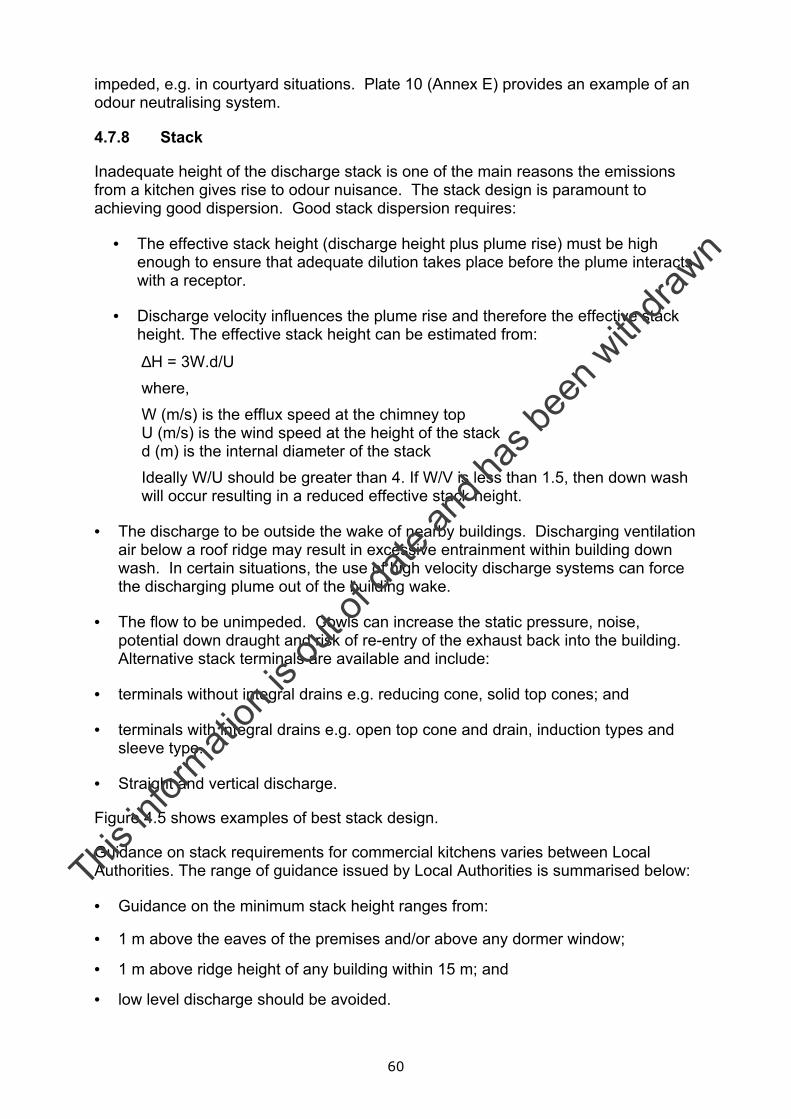
60
impeded, e.g. in courtyard situations. Plate 10 (Annex E) provides an example of an odour neutralising system.
4.7.8 Stack
Inadequate height of the discharge stack is one of the main reasons the emissions from a kitchen gives rise to odour nuisance. The stack design is paramount to achieving good dispersion. Good stack dispersion requires:
• The effective stack height (discharge height plus plume rise) must be high enough to ensure that adequate dilution takes place before the plume interacts with a receptor.
• Discharge velocity influences the plume rise and therefore the effective stack height. The effective stack height can be estimated from:
∆H = 3W.d/U where, W (m/s) is the efflux speed at the chimney top U (m/s) is the wind speed at the height of the stack d (m) is the internal diameter of the stack Ideally W/U should be greater than 4. If W/V is less than 1.5, then down wash will occur resulting in a reduced effective stack height.
• The discharge to be outside the wake of nearby buildings. Discharging ventilation air below a roof ridge may result in excessive entrainment within building down wash. In certain situations, the use of high velocity discharge systems can force the discharging plume out of the building wake.
• The flow to be unimpeded. Cowls can increase the static pressure, noise, potential down draught and risk of re-entry of the exhaust back into the building. Alternative stack terminals are available and include:
• terminals without integral drains e.g. reducing cone, solid top cones; and
• terminals with integral drains e.g. open top cone and drain, induction types and sleeve type.
• Straight and vertical discharge.
Figure 4.5 shows examples of best stack design.
Guidance on stack requirements for commercial kitchens varies between Local Authorities. The range of guidance issued by Local Authorities is summarised below:
• Guidance on the minimum stack height ranges from:
• 1 m above the eaves of the premises and/or above any dormer window;
• 1 m above ridge height of any building within 15 m; and
• low level discharge should be avoided.
This in
formati
on is
out o
f date
and h
as be
en w
ithdra
wn
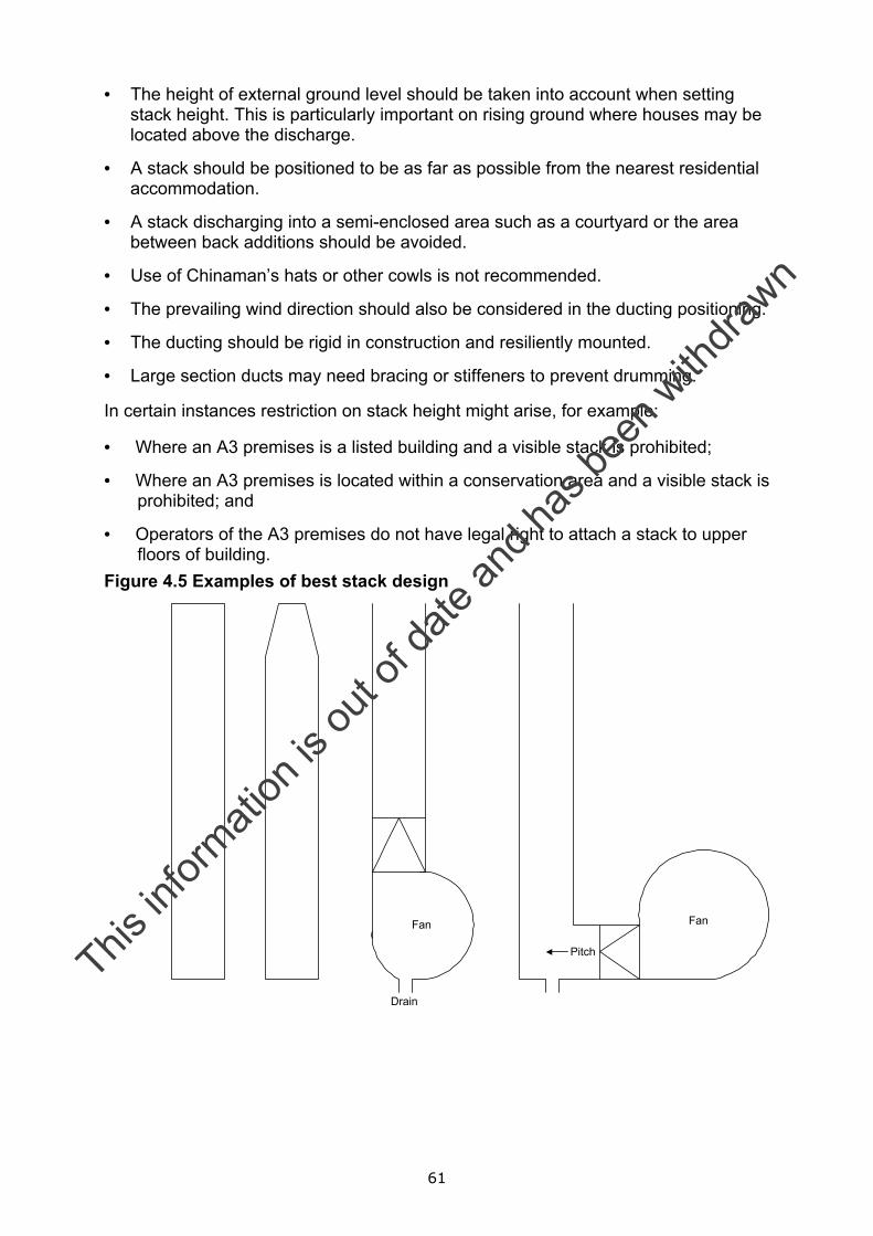
61
• The height of external ground level should be taken into account when setting stack height. This is particularly important on rising ground where houses may be located above the discharge.
• A stack should be positioned to be as far as possible from the nearest residential accommodation.
• A stack discharging into a semi-enclosed area such as a courtyard or the area between back additions should be avoided.
• Use of Chinaman’s hats or other cowls is not recommended.
• The prevailing wind direction should also be considered in the ducting positioning.
• The ducting should be rigid in construction and resiliently mounted.
• Large section ducts may need bracing or stiffeners to prevent drumming.
In certain instances restriction on stack height might arise, for example:
• Where an A3 premises is a listed building and a visible stack is prohibited;
• Where an A3 premises is located within a conservation area and a visible stack is prohibited; and
• Operators of the A3 premises do not have legal right to attach a stack to upper floors of building.
Figure 4.5 Examples of best stack design
Pitch
FanFan
Drain
This in
formati
on is
out o
f date
and h
as be
en w
ithdra
wn
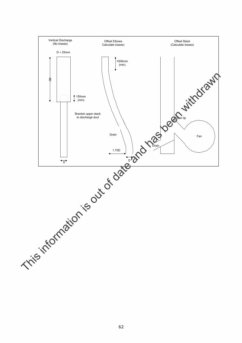
62
D + 25mm
4D
150mm(min)
D
Bracket upper stackto discharge duct
Drain
1000mm(min)
1.75D
D
Drain
Fan
Drain lip
Vertical Discharge(No losses)
Offset ElbowsCalculate losses)
Offset Stack(Calculate losses)
This in
formati
on is
out o
f date
and h
as be
en w
ithdra
wn
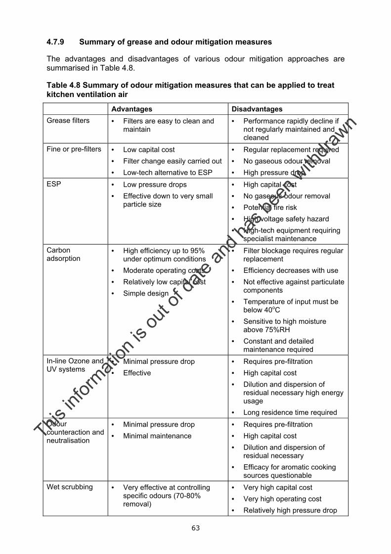
63
4.7.9 Summary of grease and odour mitigation measures
The advantages and disadvantages of various odour mitigation approaches are summarised in Table 4.8.
Table 4.8 Summary of odour mitigation measures that can be applied to treat kitchen ventilation air
Advantages Disadvantages Grease filters • Filters are easy to clean and
maintain • Performance rapidly decline if
not regularly maintained and cleaned
Fine or pre-filters • Low capital cost • Filter change easily carried out • Low-tech alternative to ESP
• Regular replacement required • No gaseous odour removal • High pressure drop
ESP • Low pressure drops • Effective down to very small
particle size
• High capital cost • No gaseous odour removal • Potential fire risk • High voltage safety hazard • High-tech equipment requiring
specialist maintenance Carbon adsorption
• High efficiency up to 95% under optimum conditions
• Moderate operating costs • Relatively low capital cost • Simple design
• Filter blockage requires regular replacement
• Efficiency decreases with use • Not effective against particulate
components • Temperature of input must be
below 40oC • Sensitive to high moisture
above 75%RH • Constant and detailed
maintenance required In-line Ozone and UV systems
• Minimal pressure drop • Effective
• Requires pre-filtration • High capital cost • Dilution and dispersion of
residual necessary high energy usage
• Long residence time required Odour counteraction and neutralisation
• Minimal pressure drop • Minimal maintenance
• Requires pre-filtration • High capital cost • Dilution and dispersion of
residual necessary • Efficacy for aromatic cooking
sources questionable Wet scrubbing • Very effective at controlling
specific odours (70-80% removal)
• Very high capital cost • Very high operating cost • Relatively high pressure drop
This in
formati
on is
out o
f date
and h
as be
en w
ithdra
wn
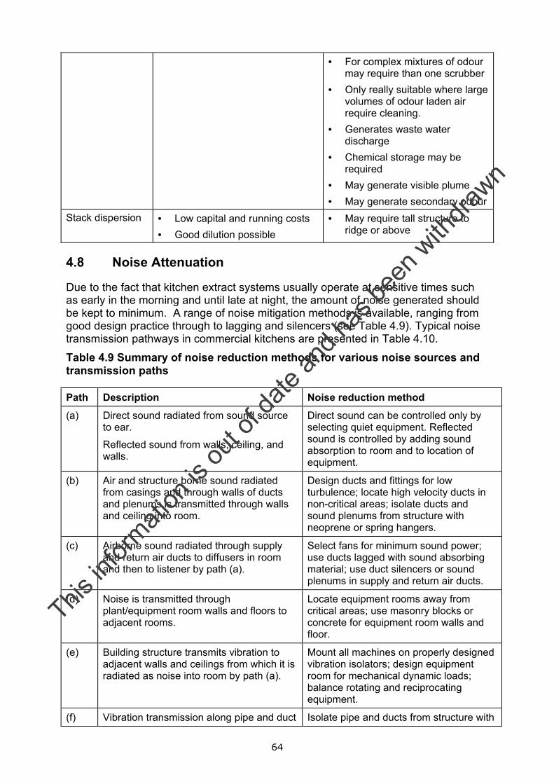
64
• For complex mixtures of odour may require than one scrubber
• Only really suitable where large volumes of odour laden air require cleaning.
• Generates waste water discharge
• Chemical storage may be required
• May generate visible plume • May generate secondary odour
Stack dispersion • Low capital and running costs • Good dilution possible
• May require tall structure to ridge or above
4.8 Noise Attenuation
Due to the fact that kitchen extract systems usually operate at sensitive times such as early in the morning and until late at night, the amount of noise generated should be kept to minimum. A range of noise mitigation methods is available, ranging from good design practice through to lagging and silencers (see Table 4.9). Typical noise transmission pathways in commercial kitchens are presented in Table 4.10.
Table 4.9 Summary of noise reduction methods for various noise sources and transmission paths Path Description Noise reduction method
(a) Direct sound radiated from sound source to ear.
Reflected sound from walls, ceiling, and walls.
Direct sound can be controlled only by selecting quiet equipment. Reflected sound is controlled by adding sound absorption to room and to location of equipment.
(b) Air and structure borne sound radiated from casings and through walls of ducts and plenums is transmitted through walls and ceiling into room.
Design ducts and fittings for low turbulence; locate high velocity ducts in non-critical areas; isolate ducts and sound plenums from structure with neoprene or spring hangers.
(c) Airborne sound radiated through supply and return air ducts to diffusers in room and then to listener by path (a).
Select fans for minimum sound power; use ducts lagged with sound absorbing material; use duct silencers or sound plenums in supply and return air ducts.
(d) Noise is transmitted through plant/equipment room walls and floors to adjacent rooms.
Locate equipment rooms away from critical areas; use masonry blocks or concrete for equipment room walls and floor.
(e) Building structure transmits vibration to adjacent walls and ceilings from which it is radiated as noise into room by path (a).
Mount all machines on properly designed vibration isolators; design equipment room for mechanical dynamic loads; balance rotating and reciprocating equipment.
(f) Vibration transmission along pipe and duct Isolate pipe and ducts from structure with
This in
formati
on is
out o
f date
and h
as be
en w
ithdra
wn
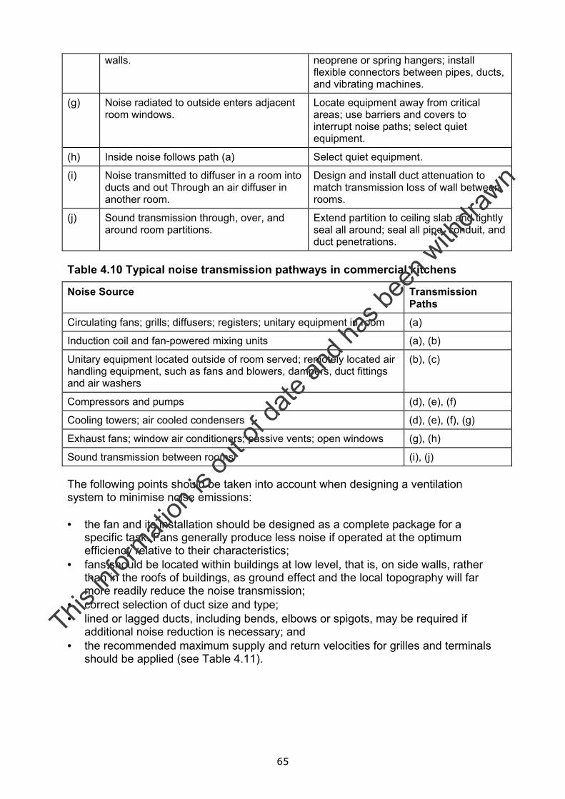
65
walls.
neoprene or spring hangers; install flexible connectors between pipes, ducts, and vibrating machines.
(g) Noise radiated to outside enters adjacent room windows.
Locate equipment away from critical areas; use barriers and covers to interrupt noise paths; select quiet equipment.
(h) Inside noise follows path (a) Select quiet equipment.
(i) Noise transmitted to diffuser in a room into ducts and out Through an air diffuser in another room.
Design and install duct attenuation to match transmission loss of wall between rooms.
(j) Sound transmission through, over, and around room partitions.
Extend partition to ceiling slab and tightly seal all around; seal all pipe, conduit, and duct penetrations.
Table 4.10 Typical noise transmission pathways in commercial kitchens
Noise Source Transmission Paths
Circulating fans; grills; diffusers; registers; unitary equipment in room (a)
Induction coil and fan-powered mixing units (a), (b)
Unitary equipment located outside of room served; remotely located air handling equipment, such as fans and blowers, dampers, duct fittings and air washers
(b), (c)
Compressors and pumps (d), (e), (f)
Cooling towers; air cooled condensers (d), (e), (f), (g)
Exhaust fans; window air conditioners; passive vents; open windows (g), (h)
Sound transmission between rooms (i), (j) The following points should be taken into account when designing a ventilation system to minimise noise emissions: • the fan and its installation should be designed as a complete package for a
specific task. Fans generally produce less noise if operated at the optimum efficiency relative to their characteristics;
• fans should be located within buildings at low level, that is, on side walls, rather than in the roofs of buildings, as ground effect and the local topography will far more readily reduce the noise transmission;
• correct selection of duct size and type; • lined or lagged ducts, including bends, elbows or spigots, may be required if
additional noise reduction is necessary; and • the recommended maximum supply and return velocities for grilles and terminals
should be applied (see Table 4.11).
This in
formati
on is
out o
f date
and h
as be
en w
ithdra
wn
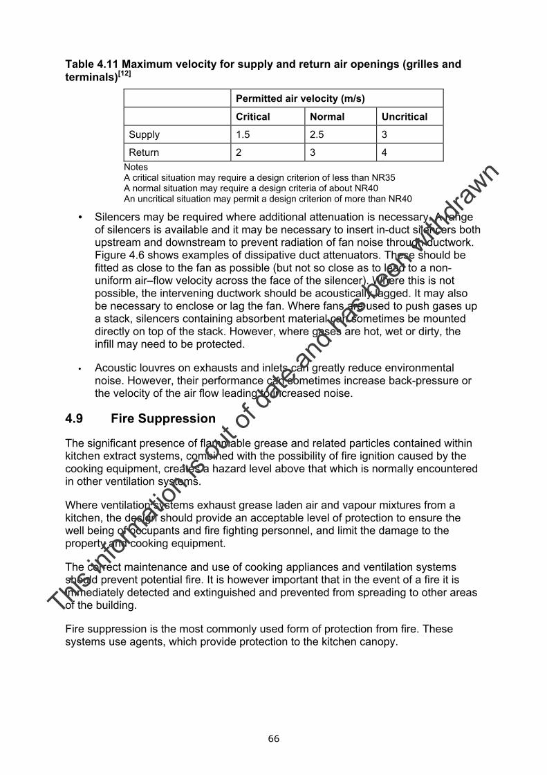
66
Table 4.11 Maximum velocity for supply and return air openings (grilles and terminals)[12]
Permitted air velocity (m/s)
Critical Normal Uncritical
Supply 1.5 2.5 3
Return 2 3 4 Notes A critical situation may require a design criterion of less than NR35 A normal situation may require a design criteria of about NR40 An uncritical situation may permit a design criterion of more than NR40
• Silencers may be required where additional attenuation is necessary. A range of silencers is available and it may be necessary to insert in-duct silencers both upstream and downstream to prevent radiation of fan noise through ductwork. Figure 4.6 shows examples of dissipative duct attenuators. These should be fitted as close to the fan as possible (but not so close as to lead to a non-uniform air–flow velocity across the face of the silencer). Where this is not possible, the intervening ductwork should be acoustically lagged. It may also be necessary to enclose or lag the fan. Where fans are used to push gases up a stack, silencers containing absorbent material can sometimes be mounted directly on top of the stack. However, where gases are hot, wet or dirty, the infill may need to be protected.
• Acoustic louvres on exhausts and inlets can greatly reduce environmental noise. However, their performance can sometimes increase back-pressure or the velocity of the air flow leading to increased noise.
4.9 Fire Suppression
The significant presence of flammable grease and related particles contained within kitchen extract systems, combined with the possibility of fire ignition caused by the cooking equipment, creates a hazard level above that which is normally encountered in other ventilation systems.
Where ventilation systems exhaust grease laden air and vapour mixtures from a kitchen, the design should provide an acceptable level of protection to ensure the well being of occupants and fire fighting personnel, and limit the damage to the property and cooking equipment.
The correct maintenance and use of cooking appliances and ventilation systems should prevent potential fire. It is however important that in the event of a fire it is immediately detected and extinguished and prevented from spreading to other areas of the building.
Fire suppression is the most commonly used form of protection from fire. These systems use agents, which provide protection to the kitchen canopy.
This in
formati
on is
out o
f date
and h
as be
en w
ithdra
wn
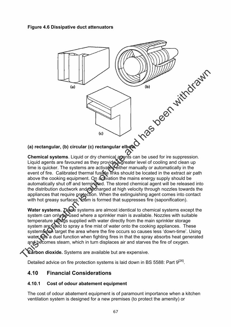
67
Figure 4.6 Dissipative duct attenuators
(a) rectangular, (b) circular (c) rectangular elbow
Chemical systems. Liquid or dry chemical agents can be used for ire suppression. Liquid agents are favoured as they provide a greater level of cooling and clean up time is quicker. The systems are activated either manually or automatically in the event of fire. Calibrated thermal fusible links should be located in the extract air path above the cooking equipment. On activation the mains energy supply should be automatically shut off and terminated. The stored chemical agent will be released into the distribution ductwork and discharged at high velocity through nozzles towards the appliances that require protection. When the extinguishing agent comes into contact with hot greasy surfaces, foam is formed that suppresses fire (saponification).
Water systems. These systems are almost identical to chemical systems except the system can only be used where a sprinkler main is available. Nozzles with suitable temperature ratings supplied with water directly from the main sprinkler storage system are used to spray a fine mist of water onto the cooking appliances. These systems can target the area where the fire occurs so causes less ‘down-time’. Using water has a duel function when fighting fires in that the spray absorbs heat generated and becomes steam, which in turn displaces air and starves the fire of oxygen.
Carbon dioxide. Systems are available but are expensive.
Detailed advice on fire protection systems is laid down in BS 5588: Part 9[26].
4.10 Financial Considerations
4.10.1 Cost of odour abatement equipment
The cost of odour abatement equipment is of paramount importance when a kitchen ventilation system is designed for a new premises (to protect the amenity) or
This in
formati
on is
out o
f date
and h
as be
en w
ithdra
wn
68
upgraded to minimise the impact of an existing premises (to prevent statutory nuisance). The factors that dictate the level of expenditure that an operator can be expected to pay will depend on a number of factors:
• Size of the cooking facility;
• Type of food prepared;
• Type of cooking appliances used; and
• Compliance with the requirements of Best Practicable Means.
For the purpose of this report, interpreting Best Practicable Means must take into account the following:
• Local conditions and circumstances will vary from case to case and will depend on the proximity of residential properties and local planning restrictions.
• The current state of technical knowledge for controlling odour is described in section 4.7 of this report. It is recognised that developments are continuously being made in the field of emissions control, so due regard must be given to any new techniques/technologies that can be designed to suit the commercial kitchen situation.
• The financial implications of odour control must be weighed against the harm caused by emission of offensive odour to local residents.
• Operation of the site for example, the design, installation, maintenance and manner, periods of operation of plant and machinery, and the design, construction and maintenance of buildings and structures etc.
In this section the typical costs of two ventilation systems are presented based on:
• a general kitchen operation situation (Table 4.12); and
• a high or very high grease/smoke situation (Table 4.13). This system involves a second pass through an ESP.
The costing provide an indication of:
• capital cost (not including installation);
• monthly maintenance and running costs; and
• annual maintenance and running costs.
The costings presented in Table 4.12 and 4.13 are based on typical costs 2004 and consider the following scenarios:
• general situation treated using pre filter panel followed by bag filter (i.e. only grease control);
• general situation treated using pre filter panel followed by bag and HEPA filter (i.e. only grease control);
• general situation treated using pre and fine filters followed by activated carbon;
This in
formati
on is
out o
f date
and h
as be
en w
ithdra
wn

69
• general situation treated using pre filter panel, bag filter and HEPA filter followed by activated carbon;
• general situation treated using an ESP followed by activated carbon;
• general situation treated using an ESP followed by odour counteractant;
• general situation treated using an ESP followed by in-line UV/ozone system;
• high or very high grease/smoke situation using an ESP followed by activated carbon;
• high or very high grease/smoke situation using an ESP followed by odour counteractant; and
• high or very high grease/smoke situation using an ESP followed by in-line UV/ozone system.
This in
formati
on is
out o
f date
and h
as be
en w
ithdra
wn

70
Table 4.12 Anticipated cost of abatement treating odour emissions from a general kitchen operation situation including maintenance and running (M&R) costs
Design Flow Rate (m/s3)
Abatement System Capital Cost
Monthly M & R Cost
Annual M & R Cost
Total Yearly cost
Panel and Bag £1,500 £160 £1,100 £3,020
Panel, Bag and HEPA £3,000 £160 £1,800 £3,720
Pre, Fine and CF £1,500 £160 £1,700 £3,620
Panel, Bag, HEPA and CF
£7,000 £160 £3,400 £5,320
ESP and CF £4,500 £125 £800 £2,300
ESP and counteractant
£5,000 £150 £0 £1,800
Up to 1.5
ESP and UV/ozone £7,000 £135 £ 450 £2,070
Panel and Bag £2,000 £180 £1,300 £3,460
Panel, Bag and HEPA £5,000 £180 £2,300 £4,460
Pre, Fine and CF £3,000 £180 £3,400 £5,560
Panel, Bag, HEPA and CF
£9,000 £180 £3,900 £6,060
ESP and CF £8,000 £150 £1400 £3,200
ESP and counteractant
£7000 £175 £0 £2,100
Up to 2
ESP and UV/ozone £10,000 £160 £900 £2,820
Panel and Bag £2,500 £200 £1,500 £3,900
Panel, Bag and HEPA £4,000 £200 £2,500 £4,900
Panel, Bag and HEPA a
£9,500 £200 £4,200 £6,600
ESP and CF £8,000 £150 £900 £2,700
ESP and counteractant
£7000 £175 £0 £2,100
2.5
ESP and UV/ozone £11,000 £175 £1,400 £3,500
Panel and Bag £4,000 £275 £2,600 £5,900
Panel, Bag and HEPA £8,000 £275 £4,500 £7,800
Pre, Fine and CF £4,500 £275 £5,100 £8,400
Panel, Bag, HEPA and CF
£17,500 £275 £7,600 £10,900
ESP and CF £11,500 £175 £2,100 £4,200
ESP and counteractant
£10,500 £200 £0 £2,400
3.5
ESP and UV/ozone £17,385 £195 £1,800 £4,140
This in
formati
on is
out o
f date
and h
as be
en w
ithdra
wn

71
Panel and Bag £5,000 £335 £3,000 £7,020
Panel, Bag and HEPA £9,000 £335 £4,900 £8,920
Pre, Fine and CF £6,000 £335 £6,800 £10,820
Panel, Bag, HEPA and CF
£19,000 £335 £8,400 £12,420
ESP and CF £12,000 £175 £2,700 £4,800
ESP and counteractant
£10,500 £225 £0 £2,700
4.5
ESP and UV/ozone £23,000 £215 £2,700 £5,280
This in
formati
on is
out o
f date
and h
as be
en w
ithdra
wn
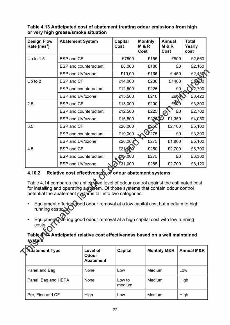
72
Table 4.13 Anticipated cost of abatement treating odour emissions from high or very high grease/smoke situation
Design Flow Rate (m/s3)
Abatement System Capital Cost
Monthly M & R Cost
Annual M & R Cost
Total Yearly cost
ESP and CF £7500 £155 £800 £2,660
ESP and counteractant £8,000 £180 £0 £2,160
Up to 1.5
ESP and UV/ozone £10,00 £165 £ 450 £2,430
ESP and CF £14,000 £200 £1400 £3,800
ESP and counteractant £12,500 £225 £0 £2,700
Up to 2
ESP and UV/ozone £15,500 £210 £900 £3,420
ESP and CF £13,000 £200 £900 £3,300
ESP and counteractant £12,500 £225 £0 £2,700
2.5
ESP and UV/ozone £16,500 £225 £1,350 £4,050
ESP and CF £20,000 £250 £2,100 £5,100
ESP and counteractant £19,000 £275 £0 £3,300
3.5
ESP and UV/ozone £26,000 £275 £1,800 £5,100
ESP and CF £21,000 £250 £2,700 £5,700
ESP and counteractant £19,000 £275 £0 £3,300
4.5
ESP and UV/ozone £31,000 £285 £2,700 £6,120
4.10.2 Relative cost effectiveness of odour abatement systems
Table 4.14 compares the anticipated level of odour control against the estimated cost for installing and operating a system. Of those systems that contain odour control potential the abatement systems fall into two categories:
• Equipment offering good odour removal at a low capital cost but medium to high running costs; or
• Equipment offering good odour removal at a high capital cost with low running costs.
Table 4.14 Anticipated relative cost effectiveness based on a well maintained system
Abatement Type Level of Odour Abatement
Capital Monthly M&R Annual M&R
Panel and Bag None Low Medium Low
Panel, Bag and HEPA None Low to medium
Medium High
Pre, Fine and CF High Low Medium High
This in
formati
on is
out o
f date
and h
as be
en w
ithdra
wn

73
Panel, Bag, HEPA and CF High to very high
High Medium High
ESP and CF High to very high
High Low Low
ESP and counteractant Medium to high*
High Medium None
ESP and UV/ozone High Very high Low Low
* level of abatement difficult to quantify using conventional odour measurement techniques.
This in
formati
on is
out o
f date
and h
as be
en w
ithdra
wn
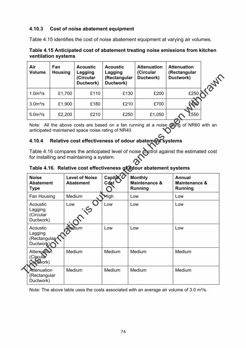
74
4.10.3 Cost of noise abatement equipment
Table 4.15 identifies the cost of noise abatement equipment at varying air volumes.
Table 4.15 Anticipated cost of abatement treating noise emissions from kitchen ventilation systems
Air Volume
Fan Housing
Acoustic Lagging (Circular Ductwork)
Acoustic Lagging (Rectangular Ductwork)
Attenuation (Circular Ductwork)
Attenuation (Rectangular Ductwork)
1.0m³/s £1,700 £110 £130 £200 £250
3.0m³/s £1,900 £180 £210 £700 £400
5.0m³/s £2,200 £210 £250 £1,050 £550
Note: All the above costs are based on a fan running at a noise rating of NR60 with an anticipated maintained space noise rating of NR40.
4.10.4 Relative cost effectiveness of odour abatement systems
Table 4.16 compares the anticipated level of noise control against the estimated cost for installing and maintaining a system.
Table 4.16. Relative cost effectiveness of odour abatement systems
Noise Abatement Type
Level of Noise Abatement
Capital Cost
Monthly Maintenance & Running
Annual Maintenance & Running
Fan Housing Medium High Low Low
Acoustic Lagging (Circular Ductwork)
Low Low Low Low
Acoustic Lagging (Rectangular Ductwork)
Medium Low Low Low
Attenuation (Circular Ductwork)
Medium Medium Medium Medium
Attenuation (Rectangular Ductwork)
Medium Medium Medium Medium
Note: The above table uses the costs associated with an average air volume of 3.0 m³/s.
This in
formati
on is
out o
f date
and h
as be
en w
ithdra
wn
75
4.11 Installation
The following qualification criteria should be considered when selecting specialist design and installation contractors.
• Experience
• Number of years designing and installing ventilation systems.
• Demonstration of track record with project references.
• Total number of operatives directly employed full time in ventilation design and installation work.
• Affiliation
• Membership of appropriate trade body.
• Quality assurance
• Work with quality systems or to accredited quality standards
• Qualifications and technical training of staff
• Health and safety
• Heath and safety policy
• Records of training and competency
• Safety/accident records
• Insurance
• Full details of any professional indemnity, employer’s liability, public liability and contractors all risk policy, clearly stating any limitations on cover.
This in
formati
on is
out o
f date
and h
as be
en w
ithdra
wn
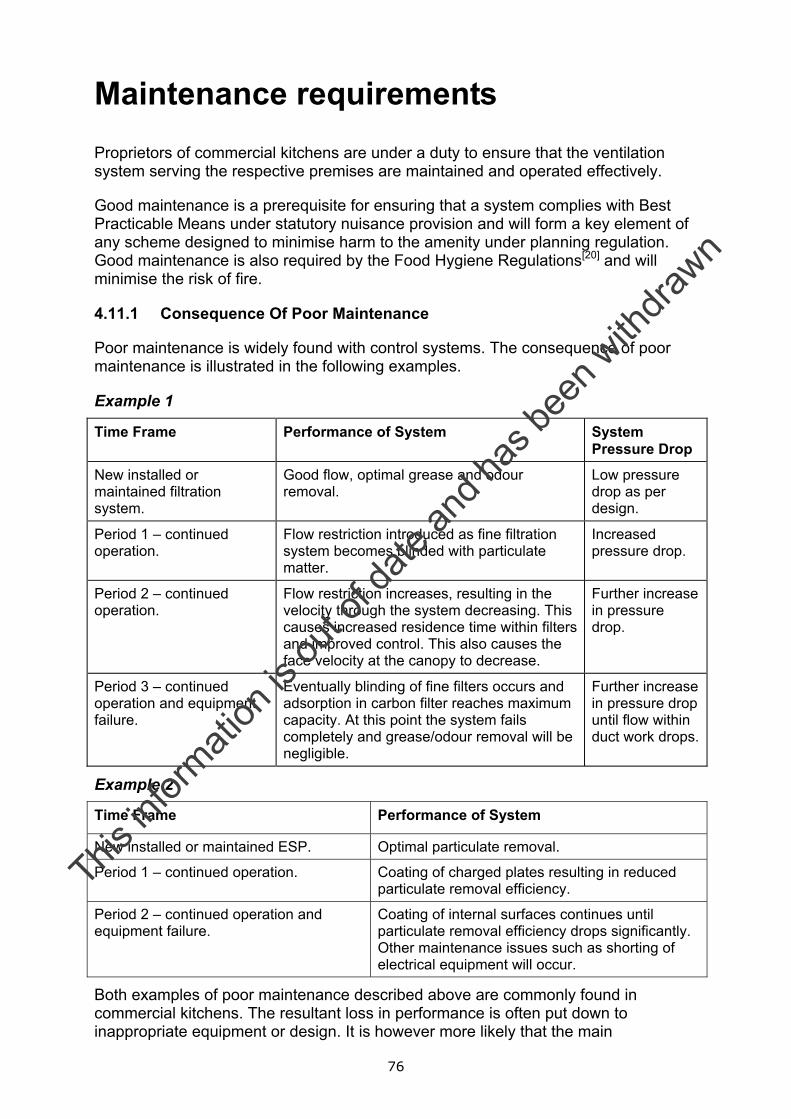
76
Maintenance requirements Proprietors of commercial kitchens are under a duty to ensure that the ventilation system serving the respective premises are maintained and operated effectively.
Good maintenance is a prerequisite for ensuring that a system complies with Best Practicable Means under statutory nuisance provision and will form a key element of any scheme designed to minimise harm to the amenity under planning regulation. Good maintenance is also required by the Food Hygiene Regulations[20] and will minimise the risk of fire.
4.11.1 Consequence Of Poor Maintenance
Poor maintenance is widely found with control systems. The consequence of poor maintenance is illustrated in the following examples.
Example 1
Time Frame Performance of System System Pressure Drop
New installed or maintained filtration system.
Good flow, optimal grease and odour removal.
Low pressure drop as per design.
Period 1 – continued operation.
Flow restriction introduced as fine filtration system becomes blinded with particulate matter.
Increased pressure drop.
Period 2 – continued operation.
Flow restriction increases, resulting in the velocity through the system decreasing. This causes increased residence time within filters and improved control. This also causes the face velocity at the canopy to decrease.
Further increase in pressure drop.
Period 3 – continued operation and equipment failure.
Eventually blinding of fine filters occurs and adsorption in carbon filter reaches maximum capacity. At this point the system fails completely and grease/odour removal will be negligible.
Further increase in pressure drop until flow within duct work drops.
Example 2
Time Frame Performance of System
New installed or maintained ESP. Optimal particulate removal.
Period 1 – continued operation. Coating of charged plates resulting in reduced particulate removal efficiency.
Period 2 – continued operation and equipment failure.
Coating of internal surfaces continues until particulate removal efficiency drops significantly. Other maintenance issues such as shorting of electrical equipment will occur.
Both examples of poor maintenance described above are commonly found in commercial kitchens. The resultant loss in performance is often put down to inappropriate equipment or design. It is however more likely that the main
This in
formati
on is
out o
f date
and h
as be
en w
ithdra
wn
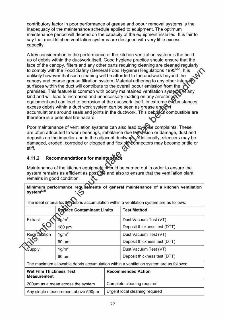
77
contributory factor in poor performance of grease and odour removal systems is the inadequacy of the maintenance schedule applied to equipment. The optimum maintenance period will depend on the capacity of the equipment installed. It is fair to say that most kitchen ventilation systems are designed with very little excess capacity.
A key consideration in the performance of the kitchen ventilation system is the build-up of debris within the ductwork itself. Good hygiene practice should ensure that the face of the canopy, filters and any other parts requiring cleaning are cleaned regularly to comply with the Food Safety (General Food Hygiene) Regulations 1995[20]. It is unlikely however that such cleaning will be afforded to the ductwork beyond the canopy and coarse grease filtration system. Material adhering to any other internal surfaces within the duct will contribute to the overall odour emission from the premises. This feature is common with poorly maintained ventilation systems of any kind and will lead to increased and unnecessary loading on any arrestment equipment and can lead to corrosion of the ductwork itself. In extreme circumstances excess debris within a duct work system can be seen as grease and dirt accumulations around seals and joints in the ductwork. This debris is combustible are therefore is a potential fire hazard.
Poor maintenance of ventilation systems can also lead to noise complaints. These are often attributed to worn bearings, imbalance due to erosion or damage, dust and deposits on the impeller and in the adjacent ductwork. Additionally, silencers may be damaged, eroded, corroded or clogged and flexible connectors may become brittle or stiff.
4.11.2 Recommendations for maintenance
Maintenance of the kitchen equipment should be carried out in order to ensure the system remains as efficient as possible and also to ensure that the ventilation plant remains in good condition.
Minimum performance requirements of general maintenance of a kitchen ventilation system[22]
The ideal criteria for the debris accumulation within a ventilation system are as follows:
Surface Contaminant Limits Test Method
Extract
6g/m2
180 µm
Dust Vacuum Test (VT)
Deposit thickness test (DTT)
Recirculation 1g/m2
60 µm
Dust Vacuum Test (VT)
Deposit thickness test (DTT)
Supply
1g/m2
60 µm
Dust Vacuum Test (VT)
Deposit thickness test (DTT)
The maximum allowable debris accumulation within a ventilation system are as follows:
Wet Film Thickness Test Measurement
Recommended Action
200µm as a mean across the system Complete cleaning required
Any single measurement above 500µm Urgent local cleaning required
This in
formati
on is
out o
f date
and h
as be
en w
ithdra
wn
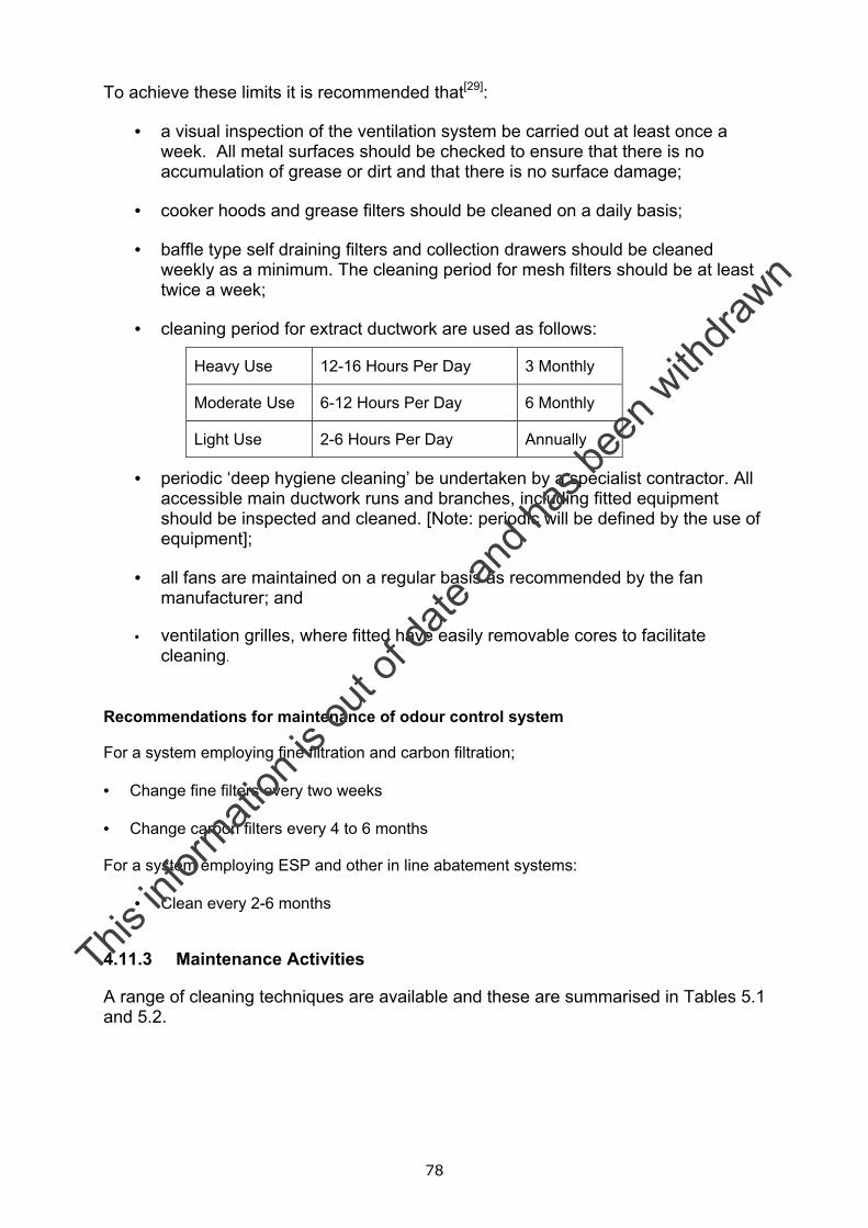
78
To achieve these limits it is recommended that[29]:
• a visual inspection of the ventilation system be carried out at least once a week. All metal surfaces should be checked to ensure that there is no accumulation of grease or dirt and that there is no surface damage;
• cooker hoods and grease filters should be cleaned on a daily basis;
• baffle type self draining filters and collection drawers should be cleaned weekly as a minimum. The cleaning period for mesh filters should be at least twice a week;
• cleaning period for extract ductwork are used as follows:
Heavy Use 12-16 Hours Per Day 3 Monthly
Moderate Use 6-12 Hours Per Day 6 Monthly
Light Use 2-6 Hours Per Day Annually
• periodic ‘deep hygiene cleaning’ be undertaken by a specialist contractor. All accessible main ductwork runs and branches, including fitted equipment should be inspected and cleaned. [Note: periodic will be defined by the use of equipment];
• all fans are maintained on a regular basis as recommended by the fan manufacturer; and
• ventilation grilles, where fitted have easily removable cores to facilitate cleaning.
Recommendations for maintenance of odour control system
For a system employing fine filtration and carbon filtration; • Change fine filters every two weeks • Change carbon filters every 4 to 6 months For a system employing ESP and other in line abatement systems:
• Clean every 2-6 months
4.11.3 Maintenance Activities
A range of cleaning techniques are available and these are summarised in Tables 5.1 and 5.2.
This in
formati
on is
out o
f date
and h
as be
en w
ithdra
wn
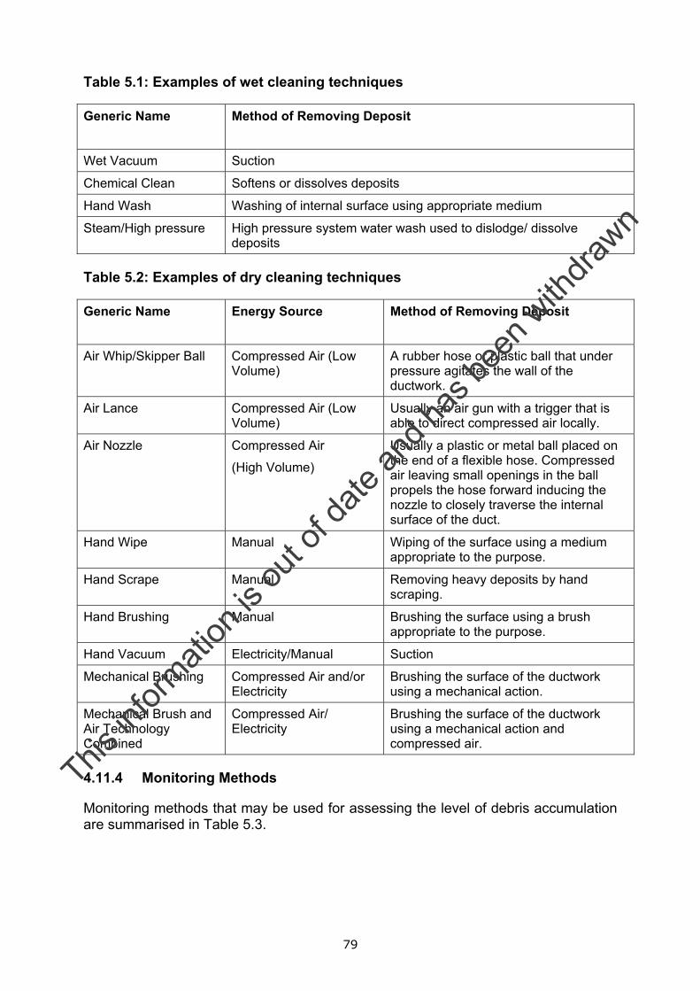
79
Table 5.1: Examples of wet cleaning techniques
Generic Name Method of Removing Deposit
Wet Vacuum Suction
Chemical Clean Softens or dissolves deposits
Hand Wash Washing of internal surface using appropriate medium
Steam/High pressure High pressure system water wash used to dislodge/ dissolve deposits
Table 5.2: Examples of dry cleaning techniques
Generic Name Energy Source
Method of Removing Deposit
Air Whip/Skipper Ball Compressed Air (Low Volume)
A rubber hose or plastic ball that under pressure agitates the wall of the ductwork.
Air Lance Compressed Air (Low Volume)
Usually an air gun with a trigger that is able to direct compressed air locally.
Air Nozzle Compressed Air
(High Volume)
Usually a plastic or metal ball placed on the end of a flexible hose. Compressed air leaving small openings in the ball propels the hose forward inducing the nozzle to closely traverse the internal surface of the duct.
Hand Wipe Manual Wiping of the surface using a medium appropriate to the purpose.
Hand Scrape Manual Removing heavy deposits by hand scraping.
Hand Brushing Manual Brushing the surface using a brush appropriate to the purpose.
Hand Vacuum Electricity/Manual Suction
Mechanical Brushing Compressed Air and/or Electricity
Brushing the surface of the ductwork using a mechanical action.
Mechanical Brush and Air Technology Combined
Compressed Air/ Electricity
Brushing the surface of the ductwork using a mechanical action and compressed air.
4.11.4 Monitoring Methods
Monitoring methods that may be used for assessing the level of debris accumulation are summarised in Table 5.3.
This in
formati
on is
out o
f date
and h
as be
en w
ithdra
wn
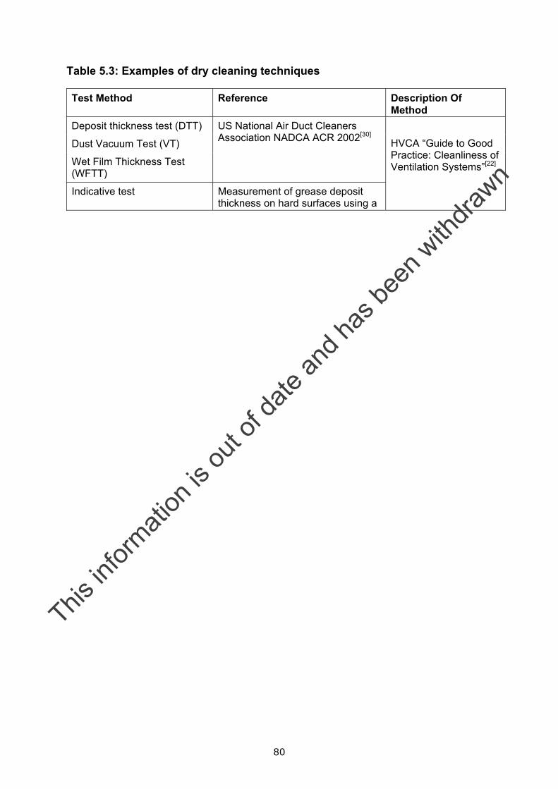
80
Table 5.3: Examples of dry cleaning techniques
Test Method Reference Description Of Method
Deposit thickness test (DTT)
Dust Vacuum Test (VT)
Wet Film Thickness Test (WFTT)
US National Air Duct Cleaners Association NADCA ACR 2002[30]
Indicative test Measurement of grease deposit thickness on hard surfaces using a
HVCA “Guide to Good Practice: Cleanliness of Ventilation Systems”[22]
This in
formati
on is
out o
f date
and h
as be
en w
ithdra
wn

81
6 Acknowledgement Netcen would like to thank The Heating and Ventilation Contractors’ Association (HVCA) for technical contribution to this work. Netcen would also like to thank those Local Environmental Health Officers who took part in the survey and to David Collins and Len Facey for their technical assistance.
This in
formati
on is
out o
f date
and h
as be
en w
ithdra
wn
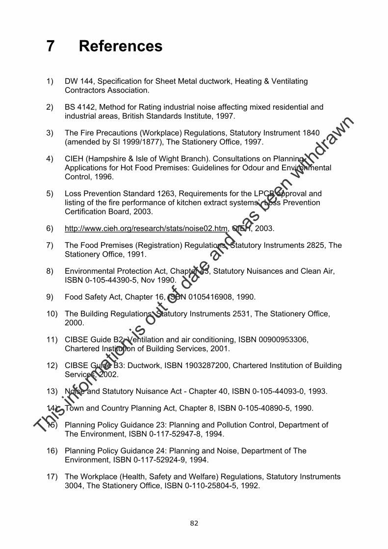
82
7 References 1) DW 144, Specification for Sheet Metal ductwork, Heating & Ventilating
Contractors Association.
2) BS 4142, Method for Rating industrial noise affecting mixed residential and industrial areas, British Standards Institute, 1997.
3) The Fire Precautions (Workplace) Regulations, Statutory Instrument 1840 (amended by SI 1999/1877), The Stationery Office, 1997.
4) CIEH (Hampshire & Isle of Wight Branch). Consultations on Planning Applications for Hot Food Premises: Guidelines for Odour and Environmental Control, 1996.
5) Loss Prevention Standard 1263, Requirements for the LPCB approval and listing of the fire performance of kitchen extract systems’, Loss Prevention Certification Board, 2003.
6) http://www.cieh.org/research/stats/noise02.htm, CIEH, 2003.
7) The Food Premises (Registration) Regulations, Statutory Instruments 2825, The Stationery Office, 1991.
8) Environmental Protection Act, Chapter 43, Statutory Nuisances and Clean Air, ISBN 0-105-44390-5, Nov 1990.
9) Food Safety Act, Chapter 16, ISBN 0105416908, 1990.
10) The Building Regulations, Statutory Instruments 2531, The Stationery Office, 2000.
11) CIBSE Guide B2: Ventilation and air conditioning, ISBN 00900953306, Chartered Institution of Building Services, 2001.
12) CIBSE Guide B3: Ductwork, ISBN 1903287200, Chartered Institution of Building Services, 2002.
13) Noise and Statutory Nuisance Act - Chapter 40, ISBN 0-105-44093-0, 1993.
14) Town and Country Planning Act, Chapter 8, ISBN 0-105-40890-5, 1990.
15) Planning Policy Guidance 23: Planning and Pollution Control, Department of The Environment, ISBN 0-117-52947-8, 1994.
16) Planning Policy Guidance 24: Planning and Noise, Department of The Environment, ISBN 0-117-52924-9, 1994.
17) The Workplace (Health, Safety and Welfare) Regulations, Statutory Instruments 3004, The Stationery Office, ISBN 0-110-25804-5, 1992.
This in
formati
on is
out o
f date
and h
as be
en w
ithdra
wn
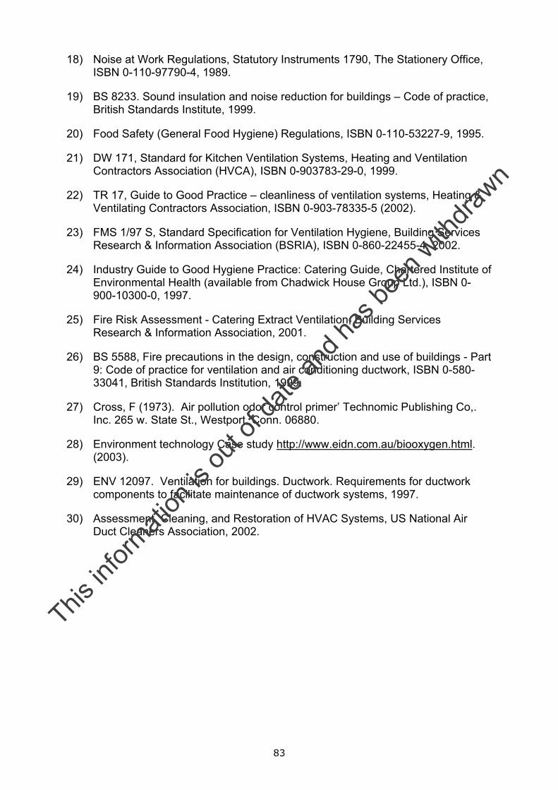
83
18) Noise at Work Regulations, Statutory Instruments 1790, The Stationery Office, ISBN 0-110-97790-4, 1989.
19) BS 8233. Sound insulation and noise reduction for buildings – Code of practice, British Standards Institute, 1999.
20) Food Safety (General Food Hygiene) Regulations, ISBN 0-110-53227-9, 1995.
21) DW 171, Standard for Kitchen Ventilation Systems, Heating and Ventilation Contractors Association (HVCA), ISBN 0-903783-29-0, 1999.
22) TR 17, Guide to Good Practice – cleanliness of ventilation systems, Heating & Ventilating Contractors Association, ISBN 0-903-78335-5 (2002).
23) FMS 1/97 S, Standard Specification for Ventilation Hygiene, Building Services Research & Information Association (BSRIA), ISBN 0-860-22455-4, 2002.
24) Industry Guide to Good Hygiene Practice: Catering Guide, Chartered Institute of Environmental Health (available from Chadwick House Group Ltd.), ISBN 0-900-10300-0, 1997.
25) Fire Risk Assessment - Catering Extract Ventilation, Building Services Research & Information Association, 2001.
26) BS 5588, Fire precautions in the design, construction and use of buildings - Part 9: Code of practice for ventilation and air conditioning ductwork, ISBN 0-580-33041, British Standards Institution, 1999.
27) Cross, F (1973). Air pollution odor control primer’ Technomic Publishing Co,. Inc. 265 w. State St., Westport, Conn. 06880.
28) Environment technology Case study http://www.eidn.com.au/biooxygen.html. (2003).
29) ENV 12097. Ventilation for buildings. Ductwork. Requirements for ductwork components to facilitate maintenance of ductwork systems, 1997.
30) Assessment, Cleaning, and Restoration of HVAC Systems, US National Air Duct Cleaners Association, 2002.
This in
formati
on is
out o
f date
and h
as be
en w
ithdra
wn
84
8 Bibliography 1) Environment Agency IPPC Horizontal Guidance for Noise (IPPC H3) Part 2 -
Noise Assessment and Control. (September 2002).
2) Environment Agency IPPC Horizontal Guidance for Odour (IPPC H4) Part 2 - Odour Assessment and Control. Working draft for consultation (October 2002).
3) Health & Safety Executive (HSE) information sheet. Ventilation of kitchens in catering establishments – Catering sheet no. 10 (March, 2000).
4) Valantin & North ‘Odour Control – A Concise Guide’ Chapter 11 “Dispersion of Odour”, (ISBN 0 85624 2144) (1980).
5) Workplace (Health, Safety and Welfare) Regulations - Approved Code of Practice and Guidance L24 (1992), (ISBN 0 11 886333 9).
This in
formati
on is
out o
f date
and h
as be
en w
ithdra
wn
85
Annex A Summary of odour and noise problems encountered by Local Authority Environmental Officers
This in
formati
on is
out o
f date
and h
as be
en w
ithdra
wn
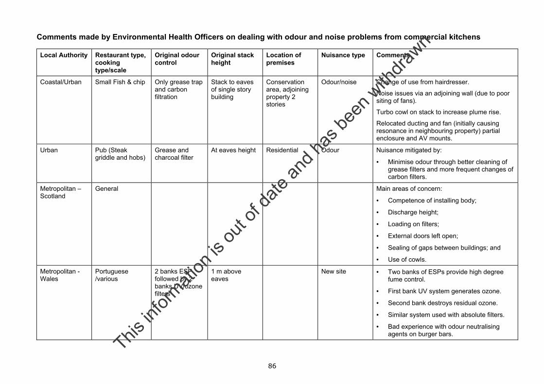
86
Comments made by Environmental Health Officers on dealing with odour and noise problems from commercial kitchens
Local Authority Restaurant type, cooking type/scale
Original odour control
Original stack height
Location of premises
Nuisance type Comments
Coastal/Urban Small Fish & chip Only grease trap and carbon filtration
Stack to eaves of single story building
Conservation area, adjoining property 2 stories
Odour/noise Change of use from hairdresser.
Noise issues via an adjoining wall (due to poor siting of fans).
Turbo cowl on stack to increase plume rise.
Relocated ducting and fan (initially causing resonance in neighbouring property) partial enclosure and AV mounts.
Urban Pub (Steak griddle and hobs)
Grease and charcoal filter
At eaves height Residential Odour Nuisance mitigated by:
• Minimise odour through better cleaning of grease filters and more frequent changes of carbon filters.
Metropolitan – Scotland
General Main areas of concern:
• Competence of installing body;
• Discharge height;
• Loading on filters;
• External doors left open;
• Sealing of gaps between buildings; and
• Use of cowls.
Metropolitan - Wales
Portuguese /various
2 banks ESP followed by 2 banks UV/ozone filters
1 m above eaves
New site • Two banks of ESPs provide high degree fume control.
• First bank UV system generates ozone.
• Second bank destroys residual ozone.
• Similar system used with absolute filters.
• Bad experience with odour neutralising agents on burger bars.
This in
formati
on is
out o
f date
and h
as be
en w
ithdra
wn
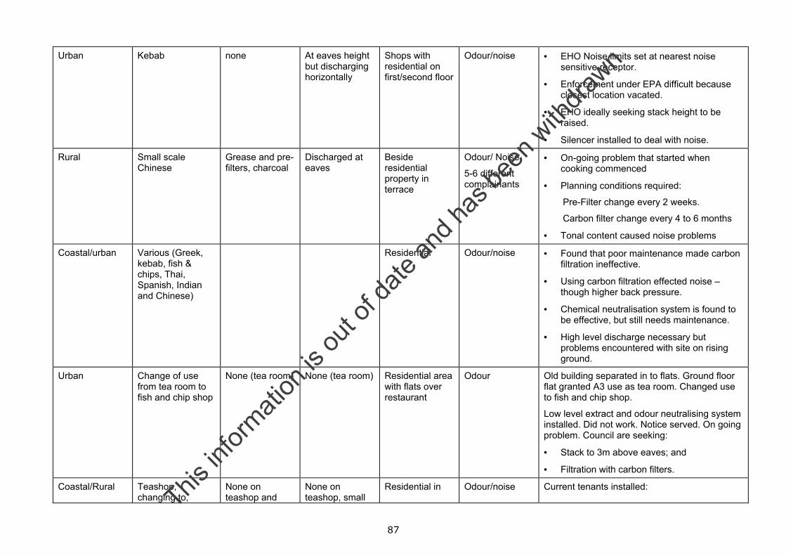
87
Urban Kebab none At eaves height but discharging horizontally
Shops with residential on first/second floor
Odour/noise • EHO Noise limits set at nearest noise sensitive receptor.
• Enforcement under EPA difficult because closest location vacated.
• EHO ideally seeking stack height to be raised.
• Silencer installed to deal with noise.
Rural Small scale Chinese
Grease and pre-filters, charcoal
Discharged at eaves
Beside residential property in terrace
Odour/ Noise
5-6 different complainants
• On-going problem that started when cooking commenced
• Planning conditions required:
Pre-Filter change every 2 weeks.
Carbon filter change every 4 to 6 months
• Tonal content caused noise problems
Coastal/urban Various (Greek, kebab, fish & chips, Thai, Spanish, Indian and Chinese)
Residential Odour/noise • Found that poor maintenance made carbon filtration ineffective.
• Using carbon filtration effected noise – though higher back pressure.
• Chemical neutralisation system is found to be effective, but still needs maintenance.
• High level discharge necessary but problems encountered with site on rising ground.
Urban Change of use from tea room to fish and chip shop
None (tea room) None (tea room) Residential area with flats over restaurant
Odour Old building separated in to flats. Ground floor flat granted A3 use as tea room. Changed use to fish and chip shop.
Low level extract and odour neutralising system installed. Did not work. Notice served. On going problem. Council are seeking:
• Stack to 3m above eaves; and
• Filtration with carbon filters.
Coastal/Rural Teashop, changing to,
None on teashop and
None on teashop, small
Residential in Odour/noise Current tenants installed:
This in
formati
on is
out o
f date
and h
as be
en w
ithdra
wn
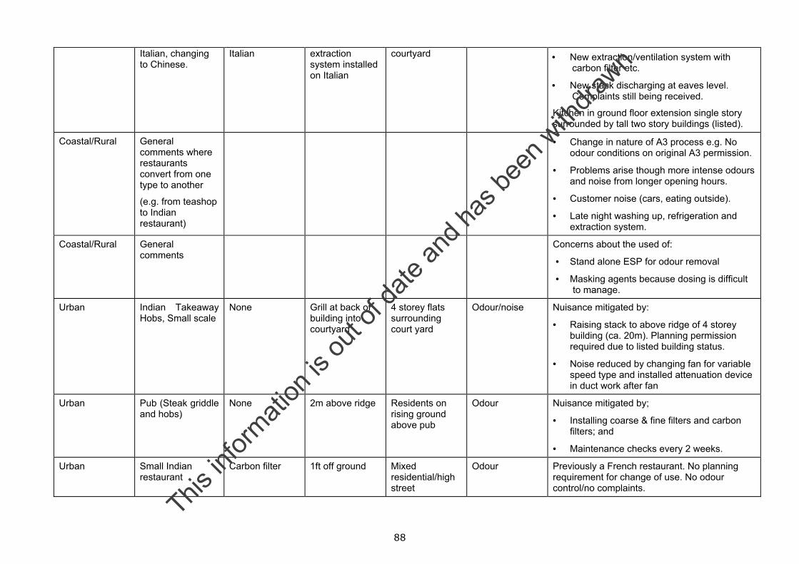
88
Italian, changing to Chinese.
Italian
extraction system installed on Italian
courtyard • New extraction/ventilation system with carbon filter etc.
• New stack discharging at eaves level. Complaints still being received.
Kitchen in ground floor extension single story surrounded by tall two story buildings (listed).
Coastal/Rural General comments where restaurants convert from one type to another
(e.g. from teashop to Indian restaurant)
• Change in nature of A3 process e.g. No odour conditions on original A3 permission.
• Problems arise though more intense odours and noise from longer opening hours.
• Customer noise (cars, eating outside).
• Late night washing up, refrigeration and extraction system.
Coastal/Rural General comments
Concerns about the used of:
• Stand alone ESP for odour removal
• Masking agents because dosing is difficult to manage.
Urban Indian Takeaway Hobs, Small scale
None Grill at back of building into courtyard
4 storey flats surrounding court yard
Odour/noise Nuisance mitigated by:
• Raising stack to above ridge of 4 storey building (ca. 20m). Planning permission required due to listed building status.
• Noise reduced by changing fan for variable speed type and installed attenuation device in duct work after fan
Urban Pub (Steak griddle and hobs)
None 2m above ridge Residents on rising ground above pub
Odour Nuisance mitigated by;
• Installing coarse & fine filters and carbon filters; and
• Maintenance checks every 2 weeks.
Urban Small Indian restaurant
Carbon filter 1ft off ground Mixed residential/high street
Odour Previously a French restaurant. No planning requirement for change of use. No odour control/no complaints.
This in
formati
on is
out o
f date
and h
as be
en w
ithdra
wn
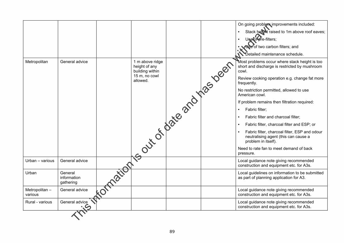
89
On going problem improvements included:
• Stack height raised to 1m above roof eaves;
• Use of pre-filters;
• Use of two carbon filters; and
• Detailed maintenance schedule.
Metropolitan General advice 1 m above ridge height of any building within 15 m, no cowl allowed.
Most problems occur where stack height is too short and discharge is restricted by mushroom cowl.
Review cooking operation e.g. change fat more frequently.
No restriction permitted, allowed to use American cowl.
If problem remains then filtration required:
• Fabric filter;
• Fabric filter and charcoal filter;
• Fabric filter, charcoal filter and ESP; or
• Fabric filter, charcoal filter, ESP and odour neutralising agent (this can cause a problem in itself).
Need to rate fan to meet demand of back pressure.
Urban – various General advice Local guidance note giving recommended construction and equipment etc. for A3s.
Urban General information gathering
Local guidelines on information to be submitted as part of planning application for A3.
Metropolitan – various
General advice Local guidance note giving recommended construction and equipment etc. for A3s.
Rural - various General advice Local guidance note giving recommended construction and equipment etc. for A3s.
This in
formati
on is
out o
f date
and h
as be
en w
ithdra
wn
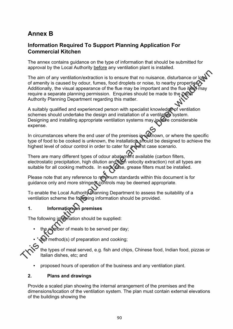
90
Annex B
Information Required To Support Planning Application For Commercial Kitchen
The annex contains guidance on the type of information that should be submitted for approval by the Local Authority before any ventilation plant is installed.
The aim of any ventilation/extraction is to ensure that no nuisance, disturbance or loss of amenity is caused by odour, fumes, food droplets or noise, to nearby properties. Additionally, the visual appearance of the flue may be important and the flue itself may require a separate planning permission. Enquiries should be made to the Local Authority Planning Department regarding this matter.
A suitably qualified and experienced person with specialist knowledge of ventilation schemes should undertake the design and installation of a ventilation system. Designing and installing appropriate ventilation systems may involve considerable expense.
In circumstances where the end user of the premises is unknown, or where the specific type of food to be cooked is unknown, the installation should be designed to achieve the highest level of odour control in order to cater for a worst case scenario.
There are many different types of odour abatement available (carbon filters, electrostatic precipitation, high dilution and high velocity extraction) not all types are suitable for all cooking methods. In each case, grease filters must be installed.
Please note that any reference to minimum standards within this document is for guidance only and more stringent controls may be deemed appropriate.
To enable the Local Authority Planning Department to assess the suitability of a ventilation scheme the following information should be provided.
1. Information on premises
The following information should be supplied:
• the number of meals to be served per day;
• the method(s) of preparation and cooking;
• the types of meal served, e.g. fish and chips, Chinese food, Indian food, pizzas or Italian dishes, etc; and
• proposed hours of operation of the business and any ventilation plant.
2. Plans and drawings
Provide a scaled plan showing the internal arrangement of the premises and the dimensions/location of the ventilation system. The plan must contain external elevations of the buildings showing the
This in
formati
on is
out o
f date
and h
as be
en w
ithdra
wn
91
• dimensions;
• route; and
• exhaust characteristics (i.e. appearance) of the ductwork in relation to the building.
The location of all filters and the fan must be clearly marked. Where the location of a filter is shown the type must be clearly identified and cross-referenced to the detailed product specification.
3. Pre-filters
A copy of the manufacturer’s product data sheet should be supplied clearly showing:
• manufacturer’s name;
• filter name and product code;
• dimensions of the pre-filter; and
• nature of the filter media.
• manufacturer’s recommendations on the frequency and type of maintenance of the pre-filter having regard to the conditions that it will be used under.
4. Electrostatic precipitators (where proposed)
A copy of the manufacturer’s product data sheet should be supplied clearly showing:
• manufacturer’s name;
• ESP name and product code;
• dimensions of the ESP; and
• flow rate rating.
Manufacturer’s recommendation on the frequency and type of maintenance of the ESP having regard to the conditions that it will be used under.
5. Carbon Filters (where proposed)
The details and type of carbon filter units should be identified. A copy of the manufacturer’s product data sheet should be supplied that clearly shows:
• manufacturer’s name;
• filter name and product code;
• dimensions of the filter panel; and
• the total number of filter panels in the filter bed.
This in
formati
on is
out o
f date
and h
as be
en w
ithdra
wn
92
The following information should also be included:
• the nature of the carbon (including product type);
• the frequency of replacement of the carbon units having regard to the conditions that it will be used under. The assumptions to this calculation must be clearly stated, including the frequency and duration of use. The manufacturer should provide recommendations on the frequency and type of maintenance required;
• total volume of carbon expressed in cubic metres;
• total mass of carbon expressed in kilograms;
• total surface area of the panels exposed to the exhausted air; and
• dwell time of the gases in the filter compartment and the control setting at which this is achieved. The assumptions to this calculation must be clearly stated, and should include the air change rate for the setting quoted.
6. Odour counteractant or neutralising system (where proposed)
The details and type of counteractant or neutralising system should be identified. A copy of the manufacturer’s product data sheet should be supplied that clearly shows:
• manufacturer’s name;
• name of delivery system and product code;
• counteractant or neutralising chemical to be used;
• COSHH data sheets for chemical to be used; and
• anticipated counteractant or neutralising delivery rate.
7. Cooker hood
The following information on the characteristics of the cooker hood should be supplied that clearly shows the:
• length that the cooker hood overhangs the appliances;
• face velocity at the cooker hood, expressed in metres per second; and
• dimensions of the opening of the cooker hood.
8. System Operation
In addition to the specification of the components the following must be provided about the system:
• extract rate (expressed as m3/s) at the proposed rate of extract;
• dwell time of the gases in the carbon filtration zone;
This in
formati
on is
out o
f date
and h
as be
en w
ithdra
wn
93
• volume of the kitchen; and
• efflux velocity
Note: The system performance is dependant upon the extract rate of the air. Where the rate can be adjusted by the use of dampers or a variable speed fan, then the conditions under which the extract rate can be achieved must be described.
9. Flue Design
The height and velocity of the final discharge are the two important factors. Generally, the greater the flue height, the better the dispersion and dilution of odours.
The discharge of air should be at a minimum height of 1m above the roof ridge, especially if there are buildings nearby that may affect odour dispersion and dilution.
Where this is not possible (e.g. because of ownership or structural constraints), additional techniques will be required in order to reduce odours, such as an increase in efflux velocity and additional filters, etc.
The final discharge should be vertically upwards, unimpeded by flue terminals. The number of bends in the ducting should be minimised and the ducting should have a smooth internal surface.
10. Noise
Data on the noise produced by the system as a whole should be provided including:
• sound power levels or sound pressure levels at given distances (the assumptions to this calculation must be clearly stated);
• an octave band analysis of the noise produced by the system should also be provided, where possible; and
• hours of operation of the ventilation system (where this differs from the hours of opening).
11. Maintenance
A schedule of maintenance must be provided including details for:
• cleaning of washable grease filters;
• frequency of inspection and replacement of all filters (grease filters, pre-filters and carbon filters where proposed);
• inspection and servicing of fans; and
• if schedule is not based on manufacturer’s instructions include the reasons why.
This in
formati
on is
out o
f date
and h
as be
en w
ithdra
wn
94
12. Additional notes for guidance
The air inlets must not permit pests to enter the kitchen. Fly screens are an example of how this can be achieved.
Sufficient air must be permitted into the premises to replace air extracted. The method for supplying this make-up air should be detailed. The route of the air into the kitchen must not result in its contamination, for example passage through a toilet. Separate provision must be made for ventilation of a toilet.
There must be sufficient access points to permit adequate cleaning of all the ductwork.
This in
formati
on is
out o
f date
and h
as be
en w
ithdra
wn
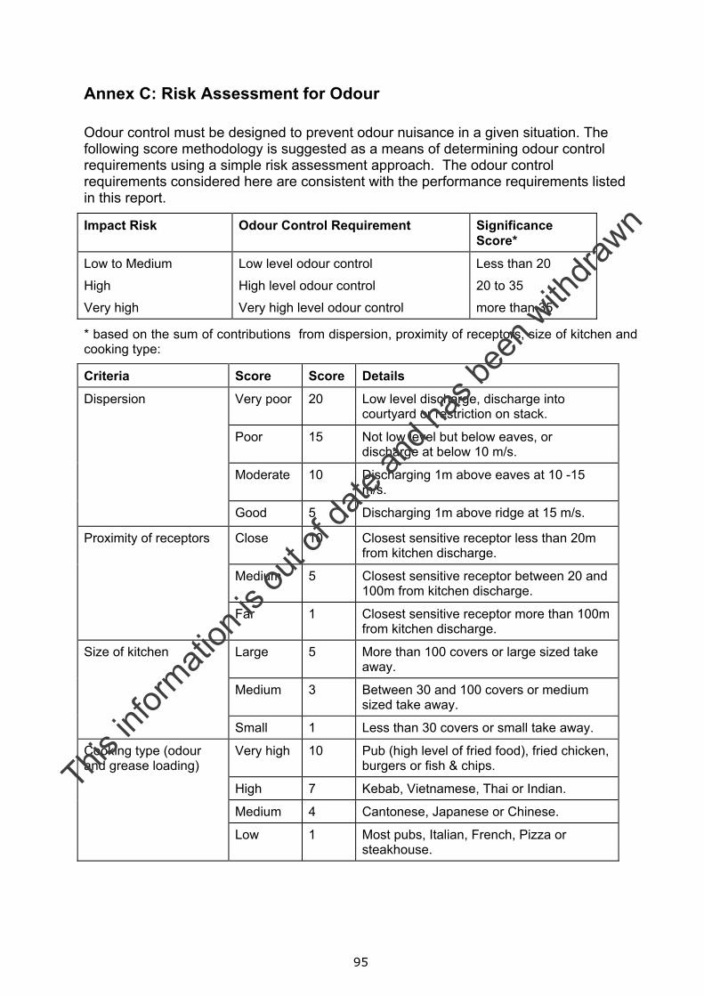
95
Annex C: Risk Assessment for Odour
Odour control must be designed to prevent odour nuisance in a given situation. The following score methodology is suggested as a means of determining odour control requirements using a simple risk assessment approach. The odour control requirements considered here are consistent with the performance requirements listed in this report.
Impact Risk Odour Control Requirement Significance Score*
Low to Medium
High
Very high
Low level odour control
High level odour control
Very high level odour control
Less than 20
20 to 35
more than 35
* based on the sum of contributions from dispersion, proximity of receptors, size of kitchen and cooking type:
Criteria Score Score Details
Very poor 20 Low level discharge, discharge into courtyard or restriction on stack.
Poor 15 Not low level but below eaves, or discharge at below 10 m/s.
Moderate 10 Discharging 1m above eaves at 10 -15 m/s.
Dispersion
Good 5 Discharging 1m above ridge at 15 m/s.
Close 10 Closest sensitive receptor less than 20m from kitchen discharge.
Medium 5 Closest sensitive receptor between 20 and 100m from kitchen discharge.
Proximity of receptors
Far 1 Closest sensitive receptor more than 100m from kitchen discharge.
Large 5 More than 100 covers or large sized take away.
Medium 3 Between 30 and 100 covers or medium sized take away.
Size of kitchen
Small 1 Less than 30 covers or small take away.
Very high 10 Pub (high level of fried food), fried chicken, burgers or fish & chips.
High 7 Kebab, Vietnamese, Thai or Indian.
Medium 4 Cantonese, Japanese or Chinese.
Cooking type (odour and grease loading)
Low 1 Most pubs, Italian, French, Pizza or steakhouse.
This in
formati
on is
out o
f date
and h
as be
en w
ithdra
wn
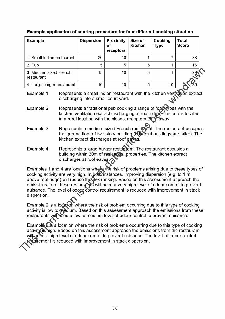
96
Example application of scoring procedure for four different cooking situation
Example Dispersion
Proximity of receptors
Size of Kitchen
Cooking Type
Total Score
1. Small Indian restaurant 20 10 1 7 38
2. Pub 5 5 5 1 16
3. Medium sized French restaurant
15 10 3 1 29
4. Large burger restaurant 10 10 5 10 35
Example 1 Represents a small Indian restaurant with the kitchen ventilation extract discharging into a small court yard.
Example 2 Represents a traditional pub cooking a range of food types with the kitchen ventilation extract discharging at roof ridge. The pub is located in a rural location with the closest receptors 25 m away.
Example 3 Represents a medium sized French restaurant. The restaurant occupies the ground floor of two story building (adjacent buildings are taller). The kitchen extract discharges at roof eaves.
Example 4 Represents a large burger restaurant. The restaurant occupies a building within 20m of residential properties. The kitchen extract discharges at roof eaves.
Examples 1 and 4 are locations where the risk of problems arising due to these types of cooking activity are very high. In both instances, improving dispersion (e.g. to 1 m above roof ridge) will reduce the risk ranking. Based on this assessment approach the emissions from these restaurants will need a very high level of odour control to prevent nuisance. The level of odour control requirement is reduced with improvement in stack dispersion.
Example 2 is a location where the risk of problem occurring due to this type of cooking activity is low to medium. Based on this assessment approach the emissions from these restaurants will need a low to medium level of odour control to prevent nuisance.
Example 3 is a location where the risk of problems occurring due to this type of cooking activity is high. Based on this assessment approach the emissions from the restaurant will need a high level of odour control to prevent nuisance. The level of odour control requirement is reduced with improvement in stack dispersion.
This in
formati
on is
out o
f date
and h
as be
en w
ithdra
wn

97
Annex D: Factors to take into account in noise assessment
Two fundamental categories of noise source are of relevance. The first is the noise produced by the fan, which is a function of the type of fan (axial, centrifugal, mixed flow, etc), the rate of the airflow and the pressure drop. For these calculations the octave band sound power from the fan is required. This can normally be obtained from the manufacturer.
The second category of noise is generated by turbulence as the air passes within the ducts or through the exit grille or louvre. In this case the amount of noise is determined by the design of duct, grille or louvre, the pressure drop across terminations, the velocity of the air (this can be variable across the duct, grille or louvre) and the area of the duct or opening. The problem with this form of noise, especially at terminations, is that in most situations it can only be controlled at its source. For example, at the feature that is generating the noise as there is no further length of duct in which to install noise control equipment.
In some situations a third source may need to be considered. This is where noise generated within the building breaks into the ductwork and is radiated from the outlet. The area of the duct walls, the acoustic properties of the duct walls and the area of any inlets determine the amount of break-in noise. Once this noise has broken into the ducts it can be treated as if it were an additional component of the fan noise. However, the nature of this additional noise is such that it usually contains a relatively high level of low frequency sound which can be difficult to attenuate.
The attenuation of fan noise (and break-in noise) provided by the ductwork is determined by the length of the ducts, the presence of any bends, changes in cross-section, the presence of any plenum chambers and termination effects (including sound-attenuating louvres if present and the attenuation provided by any change in cross-section). A balance has to be struck between the acoustic benefit of bends and louvres etc and the pressure drop that these create, possibly requiring a larger fan.
The sound energy components arising from fan noise, turbulence within the duct and at outlets, and from noise break-in, combine to produce an acoustic source at the outlet. The energy will then propagate away from the outlet in a manner determined by the nature and geometry of surrounding buildings and terrain. The nature, temporal characteristic and level of the resultant sound that reaches the ears of people in the vicinity (usually quantified by considering the noise at façades), and its level relative to the background noise, all contribute to its potential to cause disturbance and complaint. These factors should be taken into account at the planning stage as a matter of course. They form the basis of BS 4142 “Rating industrial noise affecting mixed residential and industrial areas[2]” which will often be used by a Local Authority as support to the issue of a Noise Abatement Notice under the Environmental Protection Act.
When mitigation is required it can be provided in a variety of ways. For example, if the problem is grille/louvre noise then alternative designs or relocation of the outlet are usually the only available solutions. However, with fan noise many of the basic parameters can be altered to achieve a reduction in the sound pressure level. These may include the selection of a quieter fan or adding an additional attenuator close to the fan.
This in
formati
on is
out o
f date
and h
as be
en w
ithdra
wn

98
Although there will be exceptions it is worth noting that it is usually most effective to control the noise at source, for example by using quiet fans and grilles/louvres. The next most effective form of control is to increase the attenuation in the propagation path, close to the source wherever possible (plenum chambers, bends, branches and purpose-built attenuators). The least effective approach is likely to be relocation of the outlet.
The process that should be followed in order to ensure efficient management of environmental noise when planning new ventilation systems or designing retro-fitted mitigation, for example when the Local Authority has identified that a nuisance exists, is shown in Figure D1.
This in
formati
on is
out o
f date
and h
as be
en w
ithdra
wn
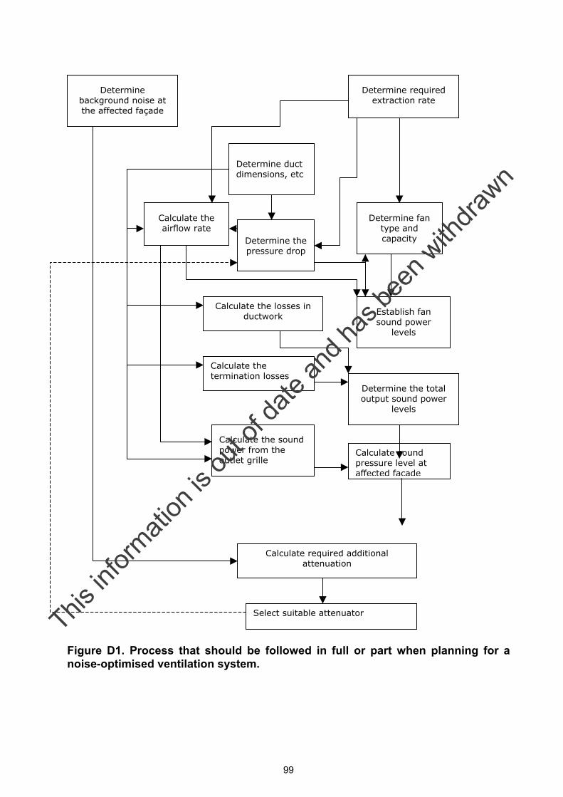
99
Figure D1. Process that should be followed in full or part when planning for a noise-optimised ventilation system.
Determine background noise at the affected façade
Determine required extraction rate
Determine duct dimensions, etc
Determine the pressure drop
Determine fan type and capacity
Establish fan sound power
levels
Calculate the losses in ductwork
Calculate the termination losses
Determine the total output sound power
levels
Calculate the sound power from the outlet grille
Calculate the airflow rate
Calculate sound pressure level at affected façade
Calculate required additional attenuation
Select suitable attenuator This in
formati
on is
out o
f date
and h
as be
en w
ithdra
wn


![Panasonic...Durian odour 6 Natural reduction 60tmin.] Sweat odour Nonanoic acid Natural reduction 120[min.] Garbage odour Methylmercaptan Natural reduction 601minJ Scalp odour Panasonic](https://img.pdfslide.net/doc/110x75/60d72199474aa2073d394000/panasonic-durian-odour-6-natural-reduction-60tmin-sweat-odour-nonanoic-acid.jpg)