Embed Size (px)
Citation preview
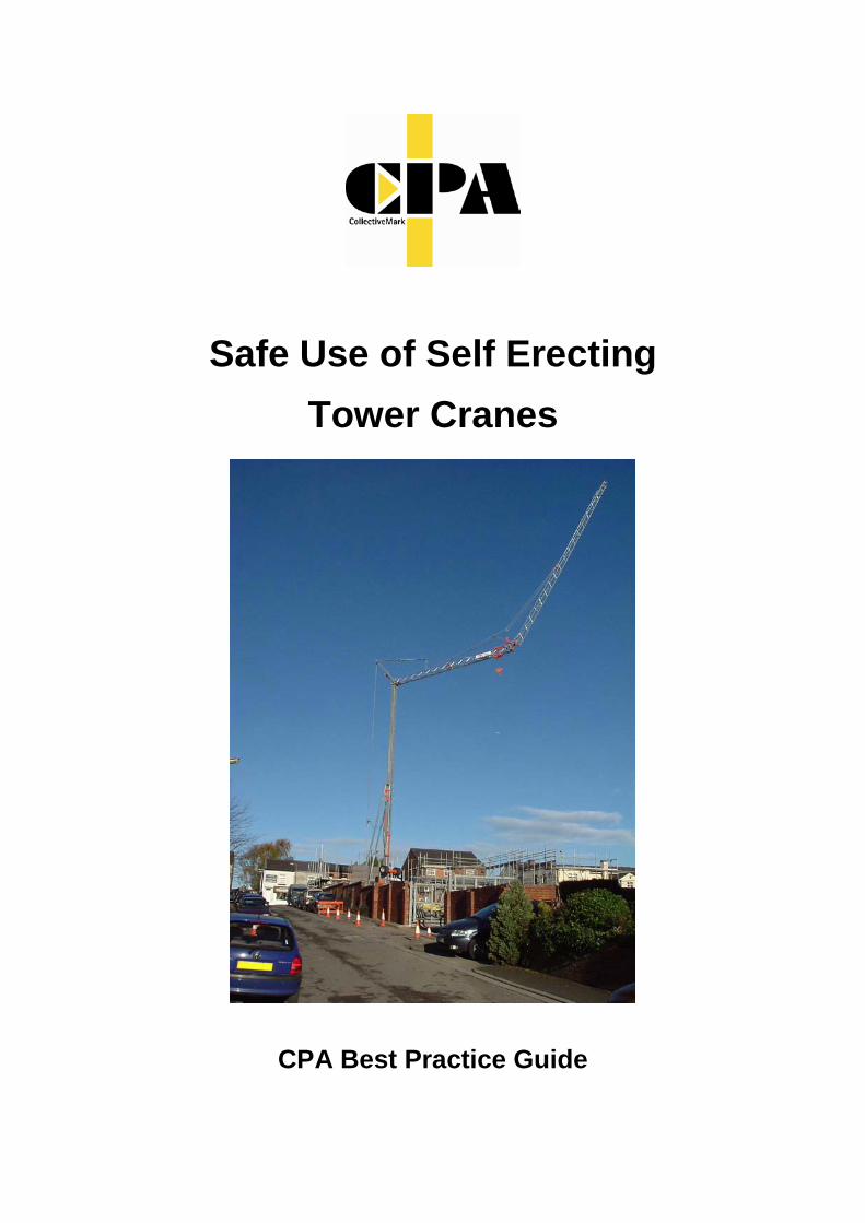
Safe Use of Self Erecting Tower Cranes
CPA Best Practice Guide
2
Safe Use of Self Erecting Tower Cranes
CPA Best Practice Guide
Working in Partnership
First Published May 2006 2nd Edition October 2006 3rd Edition May 2010 Published by:
Tower Crane Interest Group (TCIG) Construction Plant-hire Association 27/28 Newbury St London EC1A 7HU Telephone: 020 7796 3366 Email: [email protected] © CPA Copyright – 2006 & 2010
3
Contents Page
Foreword ……………………………………………………………………. 4
1. Introduction …………………………………………………………………. 5
2. Types of Hire Contract ……………………………………………………... 6
3. Planning ……………………………………………………………………... 8
4. Duties of Persons Involved in Lifting Operations ……………………….. 16
5. Selection and Training ….…………………………………………………. 20
6. Siting of SETCs ..…………………………………………………………… 22
7. SETC Operation …………………………………………………………..... 29
8. Lifting Accessories ………………………………………………………..... 33
9. Transportation to Site including loading and unloading ………………… 34
10. Erection, Alteration and Dismantling ……………………………………... 35
11. Checks, Inspections and Maintenance ...………………………………… 38
12. Thorough Examination …………………………………………………...... 40
Annex A Definitions ……………………………………………………………. 41
Annex B Examples of Categorisation of Lifts ………………………………. 44
Annex C Example of a Lifting Schedule …………………………………….. 46
Annex D Example of a Method Statement Format (Lift Plan) …………….. 48
Annex E Example of a Lifting Accessory Register ……………………….... 53
Annex F Example of a Daily Check List …………………………………….. 54
Annex G Example of a Foundation Completion Form ……………………... 55
Annex H Work at Height ………………………………………………………. 56
Annex I Guidance on the Lifting of Persons ……………………………….. 61
Annex J Radio Communications for Lifting Operations …………………… 65
Annex K Blind Lifting ………………………………………………………….. 68
Annex L Examples of Good and Bad Practice ……………………………. 69
Annex M Further Information and Guidance ………………………………... 73
Annex N Working Group Membership ………………………………………. 76
NOTE: Whilst every care has been taken to ensure the accuracy of the material contained within this booklet, no liability is accepted by the Construction Plant-hire Association in respect of the information given. Compliance with this document cannot confer immunity from legal obligations. No material from this booklet may be reproduced in any shape or form without the permission of the Construction Plant-hire Association.
4
Foreword The Construction Plant-hire Association (CPA) has, for many years, been in the vanguard of plant safety. This CPA Best Practice Guide on the Safe Use of Self Erecting Tower Cranes is one of a number of guidance documents which confirm the Association’s continued and dedicated commitment to safety and training.
Self Erecting Tower Cranes (SETCs) are now commonplace on medium and small construction sites in the UK, where the cost and complexity of conventional top slew tower cranes is not justified. Whilst the SETC brings many benefits in terms of efficiency and safety, particularly in the reduction of manual handling on small sites, like all lifting equipment it needs to be used safely, by adequately trained personnel, if the maximum benefits they can bring are to be seen.
This document’s aim is to provide guidance on the planning, installation, safe use, maintenance and thorough examination of SETCs. It sets out in readily understandable terms what the user of an SETC needs to do to ensure that the crane can be used safely and efficiently, including advice on the training of personnel and further sources of information.
This CPA Best Practice Guide has been produced by a very experienced team of people with an in-depth knowledge of SETCs and who understand the practical issues of using them on sites. The work has been carried out by a Working Group drawn from members of the CPA’s Tower Crane Interest Group, in partnership with specialist inspectors from the Health and Safety Executive.
The Best Practice Guide was originally published in May 2006 and has become a standard reference for all those engaged in the supply and use of SETCs in the UK. Over the intervening period there have been significant developments in both the design and use of SETCs and we have taken the opportunity to produce this revised version of the document, which reflects these developments.
On behalf of the CPA I would like to thank the members of the Working Group for all the time and effort they have spent on revising this work.
Syd Appleyard Chairman Tower Crane Interest Group Construction Plant-hire Association.
5
1.0 Introduction
Self-erecting tower cranes (SETCs) have become increasingly popular on small construction sites where the size of the project does not justify the installation of a conventional top slew tower crane. The management of the installation and use of self-erecting tower cranes follows exactly the same principles as top slew tower cranes. The details however, vary between the two generic types and the purpose of this Best Practice Guide is to provide guidance on the safe siting, erection, use, maintenance, thorough examination and dismantling of SETCs, together with the management and planning of these activities.
In addition to SETCs that are towed or transported to site on a vehicle, truck mounted tower cranes have become popular in the UK over the past few years. These cranes, which have many of the attributes of the self erecting tower crane, are permanently mounted on a mobile crane carrier chassis and in operational requirements fall between SETCs and conventional mobile cranes. This Best Practice Guide does not address many aspects of truck mounted tower crane operation. This distinct type of crane will be covered by a future Best Practice Guide
SETCs are sometimes referred to as “pedestrian operated tower cranes”. This may not always be correct, as although the majority of SETCs are operated with the operator standing on the ground adjacent to the crane using remote controls, some are provided with cabs at a high level or operating stations at the base. It is also possible for some conventional top-slew tower cranes to be operated by remote controls at ground level.
Attention is drawn to the following statutory regulations:-
The Health and Safety at Work etc. Act 1974;
The Lifting Operations and Lifting Equipment Regulations 1998 (LOLER);
The Provision and Use of Work Equipment Regulations 1998 (PUWER);
The Management of Health Safety & Welfare Regulations 1999 (MHSWR);
The Work at Height Regulations 2005 (WAHR);
The Supply of Machinery (Safety) Regulations 2008;
The Construction (Design and Management) Regulations 2007 (CDM);
Personal Protective Equipment at Work Regulations 1992 (PPE);
The Reporting of Injuries, Diseases and Dangerous Occurrences Regulations 1995 (RIDDOR);
The Air Navigation Order 2005.
6
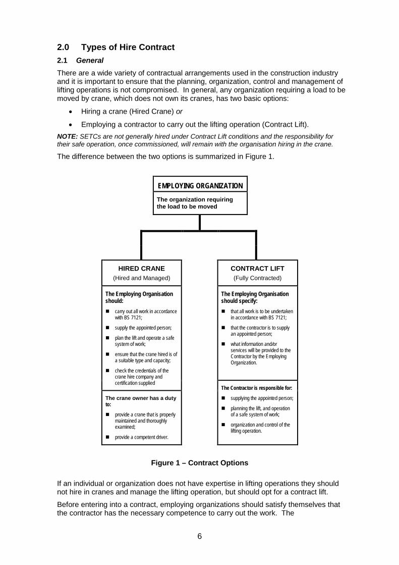
2.0 Types of Hire Contract 2.1 General There are a wide variety of contractual arrangements used in the construction industry and it is important to ensure that the planning, organization, control and management of lifting operations is not compromised. In general, any organization requiring a load to be moved by crane, which does not own its cranes, has two basic options:
• Hiring a crane (Hired Crane) or
• Employing a contractor to carry out the lifting operation (Contract Lift). NOTE: SETCs are not generally hired under Contract Lift conditions and the responsibility for their safe operation, once commissioned, will remain with the organisation hiring in the crane.
The difference between the two options is summarized in Figure 1.
EMPLOYING ORGANIZATION The organization requiring
the load to be moved
HIRED CRANE (Hired and Managed)
CONTRACT LIFT (Fully Contracted)
The Employing Organisation should: carry out all work in accordance
with BS 7121;
supply the appointed person;
plan the lift and operate a safe system of work;
ensure that the crane hired is of a suitable type and capacity;
check the credentials of the crane hire company and certification supplied
The Employing Organisation should specify: that all work is to be undertaken
in accordance with BS 7121;
that the contractor is to supply an appointed person;
what information and/or services will be provided to the Contractor by the Employing Organization.
The Contractor is responsible for:
supplying the appointed person;
planning the lift, and operation of a safe system of work;
organization and control of the lifting operation.
The crane owner has a duty to:
provide a crane that is properly maintained and thoroughly examined;
provide a competent driver.
Figure 1 – Contract Options
If an individual or organization does not have expertise in lifting operations they should not hire in cranes and manage the lifting operation, but should opt for a contract lift.
Before entering into a contract, employing organizations should satisfy themselves that the contractor has the necessary competence to carry out the work. The
7
responsibilities for insurance of the crane, personnel, the load and third parties will also need to be clarified.
2.2 Contract lifting operations The employing organization may enter into a contract with a contractor who undertakes the work on their behalf.
The parties to the contract should ensure that :-
• All work is carried out in accordance with the BS 7121 series;
• The contractor appoints a person, in accordance with Section 3 to the satisfaction of the employing organization;
• All information or services provided by the employing organization to facilitate compliance with the BS 7121 series are notified to the contractor in writing.
The contractor should carry out lifting operations in accordance with the BS 7121 series. The contractor should be given full authority by the employing organization to work in accordance with the BS 7121 series including, where appropriate, authority to control and instruct the employing organization’s personnel.
Although the BS 7121 series is intended to assist organizations to comply with their statutory and common law obligations, it does not relieve them from these obligations.
Before entering into a contract, the employing organization should ensure that the contractor has the necessary competence to carry out the work in accordance the BS 7121 series.
The normal contract conditions used for carrying out contract lifts are the Construction Plant-hire Association’s Standard Terms & Conditions for Contract Lifting Services. The user organization (hirer) should ensure that they are fully aware of their liabilities under these conditions and, if necessary, arrange for adequate additional insurance cover for possible loss of or damage to the goods being lifted.
2.3 User’s duties when using hired cranes When a crane is hired out to the user organization, the crane owner should provide a crane that is properly maintained and inspected and tested in accordance with BS 7121-2, and has a current report of thorough examination. Where an operator is provided with the crane he should be competent (see Sections 4 & 5).
The user organization retains the responsibility for nominating the appointed person in accordance with Section 3 of this document for those matters for which the appointed person is expressly made responsible and for following the recommendations given in the BS 7121 series. Although the crane owner has a duty to provide, on request, certain technical information about the crane such as outrigger loadings and duty charts to assist the user (hirer) with their planning, the responsibility for ensuring that the crane is of a suitable type, size and capacity for the task being undertaken and for planning the operation remains with the user organization.
Therefore, if an individual or organization does not have expertise in lifting operations, they should not hire cranes but should opt for a contract lift.
The normal form of contract conditions used when hiring a crane are the Construction Plant-hire Association’s Model Conditions for the Hiring of Plant (July 2001). The user organization (hirer) should ensure that they are fully aware of their liabilities under these conditions, including ground conditions, and arrange for adequate insurance cover for all risks including possible loss of or damage to the crane.
8
3.0 Planning
All lifting operations should be planned to ensure that they are carried out safely and that all foreseeable risks have been taken into account. Poor planning is one of the major causes of accidents arising from lifting operations.
The siting, setting up, use, dismantling and removal from site of a Self Erecting Tower Crane (SETC) requires careful planning if all these activities are to be carried out safely and efficiently. One person with sufficient training, practical and theoretical knowledge and experience should be appointed to be responsible for planning and supervising the tasks. This person is known as the “appointed person”.
In practice the tasks may well fall into two groups:-
• Delivery to site, erection, movement and dismantle – This will generally be carried out by the crane owner or supplier, who will carry out the planning in conjunction with the hirer and occupier of the site. The occupier of the site is responsible for ensuring that both access and foundations are adequate for the crane before it is brought on to site and erected.
• Lifting operations on site when erected. – This will normally be carried out by the hirer (user) of the SETC who is responsible for the planning, supervision and execution of each lift.
On construction sites where lifting operations are carried out by various subcontractors (including the crane supplier), the Principal Contractor should appoint the appointed person for the site. Each of the sub-contractors on site may employ individuals who have undergone appointed person training, but they should remain subservient to the Principal Contractor’s appointed person.
Both the Principal Contractor’s (hirer’s) appointed person and the crane supplier’s appointed person must ensure that the planning for each task includes the following :-
• Identifying the task to be undertaken;
• Identifying the hazards associated with the task;
• Carrying out a risk assessment;
• Identifying control measures;
• Developing the method to be used;
• Recording the planning in a Method Statement (including any contingency activities for rescue);
• Communicating the plan to all persons involved;
• Reviewing the plan before the tasks starts and incorporating any changing circumstances.
To enable lifts to be planned, supervised and carried out effectively it is helpful to categorise lifts into one of three categories - basic, intermediate and complex as detailed below.
9
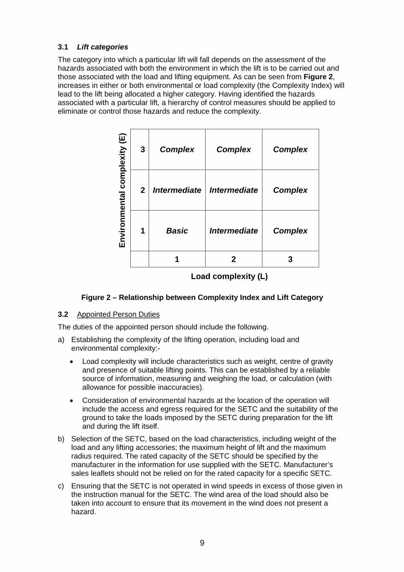
3.1 Lift categories The category into which a particular lift will fall depends on the assessment of the hazards associated with both the environment in which the lift is to be carried out and those associated with the load and lifting equipment. As can be seen from Figure 2, increases in either or both environmental or load complexity (the Complexity Index) will lead to the lift being allocated a higher category. Having identified the hazards associated with a particular lift, a hierarchy of control measures should be applied to eliminate or control those hazards and reduce the complexity.
En
viro
nmen
tal c
ompl
exity
(E)
3 Complex Complex Complex
2 Intermediate Intermediate Complex
1 Basic Intermediate Complex
1 2 3 Load complexity (L)
Figure 2 – Relationship between Complexity Index and Lift Category
3.2 Appointed Person Duties
The duties of the appointed person should include the following.
a) Establishing the complexity of the lifting operation, including load and environmental complexity:-
• Load complexity will include characteristics such as weight, centre of gravity and presence of suitable lifting points. This can be established by a reliable source of information, measuring and weighing the load, or calculation (with allowance for possible inaccuracies).
• Consideration of environmental hazards at the location of the operation will include the access and egress required for the SETC and the suitability of the ground to take the loads imposed by the SETC during preparation for the lift and during the lift itself.
b) Selection of the SETC, based on the load characteristics, including weight of the load and any lifting accessories; the maximum height of lift and the maximum radius required. The rated capacity of the SETC should be specified by the manufacturer in the information for use supplied with the SETC. Manufacturer’s sales leaflets should not be relied on for the rated capacity for a specific SETC.
c) Ensuring that the SETC is not operated in wind speeds in excess of those given in the instruction manual for the SETC. The wind area of the load should also be taken into account to ensure that its movement in the wind does not present a hazard.
10
d) Ensuring that the SETC has been thoroughly examined at least within the previous 6 months (for lifting of persons) or 12 months, inspected and checked before use. It is essential that the report of thorough examination which confirms that the equipment is safe to use is available. (See 12.0) NOTE: The report of thorough examination for the SETC should be available on site.
e) Selecting appropriate lifting accessories, including their method of attachment to the load, configuration and any protection used to prevent damage.
f) Ensuring that lifting accessories are thoroughly examined, at least within the previous 6 months, inspected and checked before use. It is essential that the report of thorough examination is available to confirm that the lifting accessories are safe to use.
g) Ensuring that a system for reporting and rectifying defects is in place.
h) Designating a suitable person to check the lifting accessories and any lifting points that are provided on the load, to ensure they are free from any obvious defect before attaching the load to the SETC.
i) Ensuring that the outcomes of the planning process are recorded in a risk assessment and method statement, which should be signed by the appointed person. NOTE: In many instances a basic lift may be covered by a generic risk assessment and a generic method statement, provided that no additional hazards are identified on site
j) Briefing all persons involved in the lifting operation to ensure that the safe system of work described in the method statement is understood. All persons involved in the lifting operation should be instructed to seek advice from the appointed person if any change is required to the lifting operation, or if any doubts about safety arise. If one or more handlines/taglines are required to give more control of the load, the appointed person should designate persons to handle the lines.
k) Checking, if numerous loads are to be lifted over a long period, that no changes are required in the safe system of work.
l) Ensuring that there is a crane supervisor (see 4.3) designated to direct personnel and that the operation is carried out in accordance with the method statement.
m) Identifying all significant hazards in the operating area, including any areas required for access or setting up of the SETC.
n) Ensuring that a site specific risk assessment and method statement, detailing control measures for the identified risks, is prepared.
o) Liaison with any other person or authority, as required to overcome any hazard, by including any necessary corrective action or special measures in the safe system of work.
p) Determining any requirement for personnel in addition to the SETC operator, such as a slinger, signaller or dedicated crane supervisor
q) Consideration of the effect of the lifting operation on surrounding property or persons, including the general public. This should lead to arranging for appropriate action to minimize any adverse effects, and to giving appropriate notice to all persons concerned.
r) Identifying all exceptional hazards in the operating area, including any areas required for access or setting up of the SETC. This will require the appointed person to visit the location of the planned lifting operation as part of the planning process.

11
s) Liaison with any other person or authority, as required to overcome any hazard, by including any necessary corrective action or special measures in the safe system of work.
t) Ensuring that the method statement includes access, ground conditions, setting up, etc., as well as the exact sequence of operations when lifting the load;
u) Preparing a sufficiently detailed and dimensioned drawing of the site, SETC and the load, identifying the load path, pick up and set down areas, together with the position of any exceptional hazards in the area. The information provided should be sufficient to enable the operator to position the SETC accurately.
v) Ensuring that where persons are being lifted, the requirements of Annex I are met.
It is essential that the appointed person is present on the site during a complex lift.
The appointed person and crane supervisor should be aware of the limits of their knowledge and experience concerning lifting operations, and when conditions exceed these limits, further advice should be sought.
For a basic lift the SETC operator may, if suitably trained and authorised, also take on the roles of the slinger and crane supervisor.
3.3 Identifying the task to be undertaken As the first stage in the planning process, the task to be undertaken should be clearly identified, together with the location and sequence.
Certain lifting operations require particular care and attention. Further advice can be found in BS 7121 Part 5. The appointed person should be familiar with these and plan the lift accordingly.
These operations include:
• lifting of persons (See Annex I);
• blind lifting (See Annex K);
• operating in hazardous environments (chemical, nuclear, power stations etc).
SETCs should not be used for tandem or multiple lifting, demolition or piling duties.
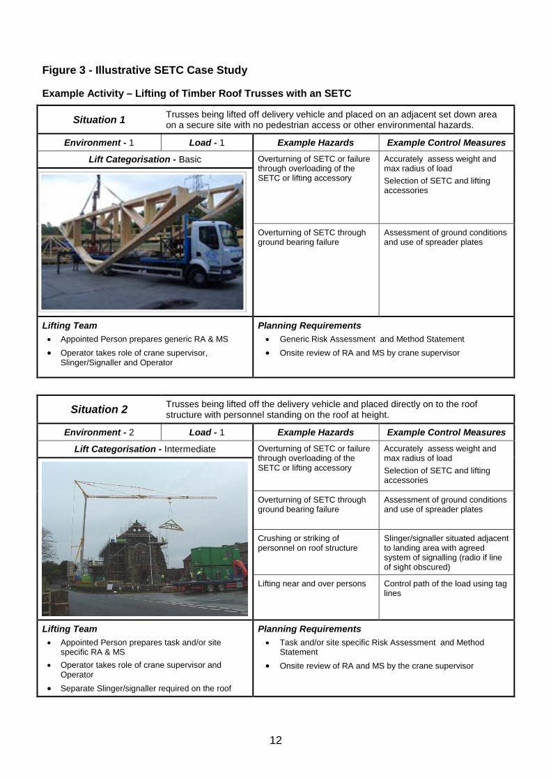
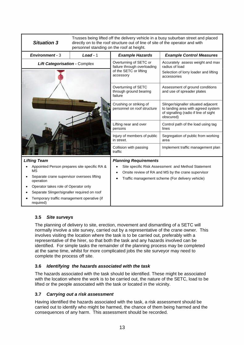
3.4 Case study The case study in Figure 3 illustrates the way in which both the complexity of the load being lifted and the environment in which the lift is taking place affect the overall complexity of the lift. The case study takes a typical lifting operation carried out by a lorry loader, the lifting of timber roof trusses. Three different situations are evaluated with examples of the hazards encountered and the control measures required to eliminate or reduce those hazards to an acceptable level. It should be noted that this is an example only and does not identify all the hazards that may be present in a given circumstance.
Examples of the categorisation of lifting operations are given in Annex B.
12
Figure 3 - Illustrative SETC Case Study
Example Activity – Lifting of Timber Roof Trusses with an SETC
Situation 1 Trusses being lifted off delivery vehicle and placed on an adjacent set down area on a secure site with no pedestrian access or other environmental hazards.
Environment - 1 Load - 1 Example Hazards Example Control Measures
Lift Categorisation - Basic Overturning of SETC or failure through overloading of the SETC or lifting accessory
Accurately assess weight and max radius of load Selection of SETC and lifting accessories
Overturning of SETC through ground bearing failure
Assessment of ground conditions and use of spreader plates
Lifting Team • Appointed Person prepares generic RA & MS • Operator takes role of crane supervisor,
Slinger/Signaller and Operator
Planning Requirements • Generic Risk Assessment and Method Statement • Onsite review of RA and MS by crane supervisor
Situation 2 Trusses being lifted off the delivery vehicle and placed directly on to the roof structure with personnel standing on the roof at height.
Environment - 2 Load - 1 Example Hazards Example Control Measures
Lift Categorisation - Intermediate Overturning of SETC or failure through overloading of the SETC or lifting accessory
Accurately assess weight and max radius of load Selection of SETC and lifting accessories
Overturning of SETC through ground bearing failure
Assessment of ground conditions and use of spreader plates
Crushing or striking of personnel on roof structure
Slinger/signaller situated adjacent to landing area with agreed system of signalling (radio if line of sight obscured)
Lifting near and over persons Control path of the load using tag lines
Lifting Team • Appointed Person prepares task and/or site
specific RA & MS • Operator takes role of crane supervisor and
Operator • Separate Slinger/signaller required on the roof
Planning Requirements • Task and/or site specific Risk Assessment and Method
Statement • Onsite review of RA and MS by the crane supervisor
13
Situation 3 Trusses being lifted off the delivery vehicle in a busy suburban street and placed directly on to the roof structure out of line of site of the operator and with personnel standing on the roof at height.
Environment - 3 Load - 1 Example Hazards Example Control Measures
Lift Categorisation - Complex Overturning of SETC or failure through overloading of the SETC or lifting accessory
Accurately assess weight and max radius of load Selection of lorry loader and lifting accessories
Overturning of SETC through ground bearing failure
Assessment of ground conditions and use of spreader plates
Crushing or striking of personnel on roof structure
Slinger/signaller situated adjacent to landing area with agreed system of signalling (radio if line of sight obscured)
Lifting near and over persons
Control path of the load using tag lines
Injury of members of public in street.
Segregation of public from working area
Collision with passing traffic
Implement traffic management plan
Lifting Team • Appointed Person prepares site specific RA &
MS • Separate crane supervisor oversees lifting
operation • Operator takes role of Operator only • Separate Slinger/signaller required on roof • Temporary traffic management operative (if
required)
Planning Requirements • Site specific Risk Assessment and Method Statement • Onsite review of RA and MS by the crane supervisor • Traffic management scheme (For delivery vehicle)
3.5 Site surveys The planning of delivery to site, erection, movement and dismantling of a SETC will normally involve a site survey, carried out by a representative of the crane owner. This involves visiting the location where the task is to be carried out, preferably with a representative of the hirer, so that both the task and any hazards involved can be identified. For simple tasks the remainder of the planning process may be completed at the same time, whilst for more complicated jobs the site surveyor may need to complete the process off site.
3.6 Identifying the hazards associated with the task The hazards associated with the task should be identified. These might be associated with the location where the work is to be carried out, the nature of the SETC, load to be lifted or the people associated with the task or located in the vicinity.
3.7 Carrying out a risk assessment Having identified the hazards associated with the task, a risk assessment should be carried out to identify who might be harmed, the chance of them being harmed and the consequences of any harm. This assessment should be recorded.
14
3.8 Identifying control measures Once the risk assessment has highlighted the risks involved in the task, the procedures and measures required to control them should be identified.
3.9 Developing the method to be used Having identified the hazards, evaluated the risks and worked out the control measures required to carry out the task safely, these components should be developed into a coherent plan. Any contingency measures and rescue procedures should be included in the plan.
3.10 Recording the planning in a Method Statement Once the plan has been developed it should be recorded in a Method Statement. The length and detail of this document depends on the complexity of the task to be undertaken and on the risks involved. A simple low risk job such as a routine lift of dry lining sheets might only require the use of a brief generic method statement, whilst a more complex and high risk job such installation of the SETC on site would require a more detailed job specific method statement. The method statement covering all planned lifting on a site is often referred to as the “lift plan”. The method statement should include a “lifting schedule” listing each type of item to be lifted together with the following information:
• Item description;
• Weight;
• Dimensions;
• Lifting points/method;
• Assess and record the lift category;
• Define the roles and any combination of roles of the lifting team;
• Type of lifting accessories to be used and configuration;
• Pick up and landing locations referenced to the site plan.
An example of a lifting schedule is shown in Annex C and an example of a method statement in Annex D.
3.11 Scale drawing The appointed person should prepare, or have drawn up under his direction, a scale drawing of the site. The drawing should include the following information:-
• Plan and side elevation views;
• Outline envelope of the building under construction;
• The planned location of the crane with dimensions to reference points to aid location;
• The make and model of crane selected;
• The radius that the crane can reach;
• SWL at max radius;
• Height under hook;
• Proximity hazards and delivery vehicle unloading areas.
15
3.12 Communicating the plan to all persons involved One of the most important aspects of successful planning is to ensure that the contents of the plan are communicated effectively to and between all parties involved, taking account of language differences. Arrangements should be made to ensure that copies of any method statements are given to the appropriate people and that others involved in the job are fully briefed. Similarly any changes to the plan should be communicated to all parties.
On a site subject to CDM, the Principal Contractor will need to review and comment on all lift plans before a lifting operation takes place on that site.
3.13 Reviewing the plan before the job starts Immediately before a job starts the risk assessment and method should be reviewed to check if any aspect of the job has changed and the effect that these changes could have on the safety of the operation. If any modifications to the plan are required these should be communicated to all those involved. The appointed person should amend the method statement (lift plan) and initial any significant changes.
3.14 Further guidance Further guidance on planning of lifting and installation is given in:
• BS 7121 Code of practice for safe use of cranes – Part 1 General and Part 5 Tower Cranes;
• L113 Safe Use of Lifting Equipment - Lifting Operations and Lifting Equipment Regulations 1998 Code of Practice - ISBN 0 7176 1628 2;
• HSE Leaflet INDG218 – Guide to Risk Assessment;
• HSE Leaflet INDG163 – Five Steps to Risk Assessment.
16
4.0 Duties of Personnel Involved in Lifting Operations
The Health and Safety at Work, etc Act 1974 demands that employers have safe systems of work, so that their employees and others are protected from any risk, so far as is reasonably practicable. Using SETCs without a safe system of work is a breach of this Act.
The British Standard Code of Practice for the Safe Use of Cranes, BS 7121 Part 5, gives advice to organisations requiring lifting operations to be carried out with SETCs and on ways of meeting their legal obligations. It also details who is responsible and what their duties are.
It is a requirement of the Lifting Operations and Lifting Equipment Regulations 1998 (LOLER 98) and BS 7121 Part 5 that one person should be appointed to have overall control of each lifting operation to ensure that it is carried out safely.
In certain circumstances it may be possible to combine some of the roles of members of the lifting team (see 4.7).
4.1 The Duties of the Appointed Person The appointed person is nominated by management of the user organisation (generally the Principal Contractor) to be in overall control of the lifting operations and the members of the lifting team. This person must have had training, experience, and be competent.
His duties include ensuring that:
• the lifting operation is properly planned and carried out;
• a suitable and sufficient risk assessment is carried out to evaluate the hazards associated with the lifting operation and identify control measures;
• planning is recorded in a lift plan which is effectively communicated to all members of the lifting team;
• accurate weights, radii, heights, etc are established;
• suitable SETCs, lifting accessories and other equipment are selected ;
• suitable access is provided to unload and store materials within the operating area of the SETC;
• competent, properly trained personnel are provided and that they are fully briefed;
• all SETCs, lifting accessories and other equipment are properly maintained, inspected, examined and tested (when necessary);
• appropriate steps are taken to exclude persons not directly involved with the lift from the lifting zone using barricades etc.
The appointed person needs to appoint a crane supervisor to be present throughout the lifting operation in order to control it and ensure that it is carried out in accordance with the planning. The appointed person may choose to act as the crane supervisor. The SETC operator must know who the crane supervisor is and, if they have any problems whilst on site, they should consult him.
The appointed person retains overall responsibility for the lifting operation and has the authority to stop the lifting operation at any time if it is considered that there is a risk to safety. If the appointed person is not present, then this authority passes to the crane supervisor.
17
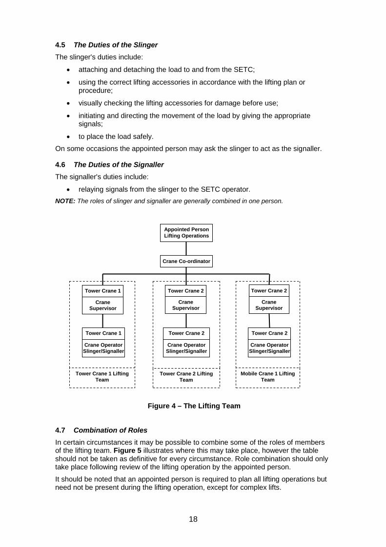
On multi-crane sites the appointed person should appoint a crane co-ordinator for the site and a crane supervisor for each crane.
Figure 3 shows the relationship between members of the “Lifting Team”
4.2 The Duties of the Crane Co-ordinator The crane co-ordinator’s duties include:
• planning and directing the sequence of operations of SETCs to ensure that they do not collide with other cranes, loads and other equipment (e.g. concrete placing booms, telehandlers, and piling rigs).
NOTE: A site with only one crane and where the risk of collision with other equipment is minimal will not require a crane co-ordinator.
4.3 The Duties of the Crane Supervisor The crane supervisor's duties include:
• ensuring that the SETC and other equipment are in accordance with the lifting plan prepared by the appointed person;
• ensuring that sufficient personnel are available to safely carry out the lifting operation;
• ensuring that the conditions on site are the same as those identified by the lifting plan;
• reporting back to the appointed person if there are any problems;
• briefing the personnel before the lifting operation begins;
• supervising and directing the slinger, signaller and SETC operator;
• only lifting items that have been detailed in the lifting plan;
• stopping the operation in the event of any risk to safety.
4.4 The Duties of the SETC Operator The SETC operator's duties include:
• establishing who is in charge of the lifting operation and the other members of the team and their roles;
• establishing which signalling system is to be used and following instructions from only one nominated signaller at a time;
• stopping operations if given any instructions that would take the SETC outside its permitted duties;
• informing the crane supervisor if any problems arise which would affect the lifting operation;
• carrying out the daily checks and weekly inspections;
• carrying out specified maintenance in accordance with the manufacturers and employer’s instruction and training;
• using the SETC to lift only the loads that are identified in the lift plan.
If the SETC operator believes that the operation they are being asked to carry out is unsafe, they should initially speak to the crane supervisor or appointed person. In the event that there is a disagreement between the operator and the crane supervisor or appointed person the operator should notify his employer.
18
4.5 The Duties of the Slinger The slinger's duties include:
• attaching and detaching the load to and from the SETC;
• using the correct lifting accessories in accordance with the lifting plan or procedure;
• visually checking the lifting accessories for damage before use;
• initiating and directing the movement of the load by giving the appropriate signals;
• to place the load safely.
On some occasions the appointed person may ask the slinger to act as the signaller.
4.6 The Duties of the Signaller The signaller's duties include:
• relaying signals from the slinger to the SETC operator. NOTE: The roles of slinger and signaller are generally combined in one person.
Figure 4 – The Lifting Team
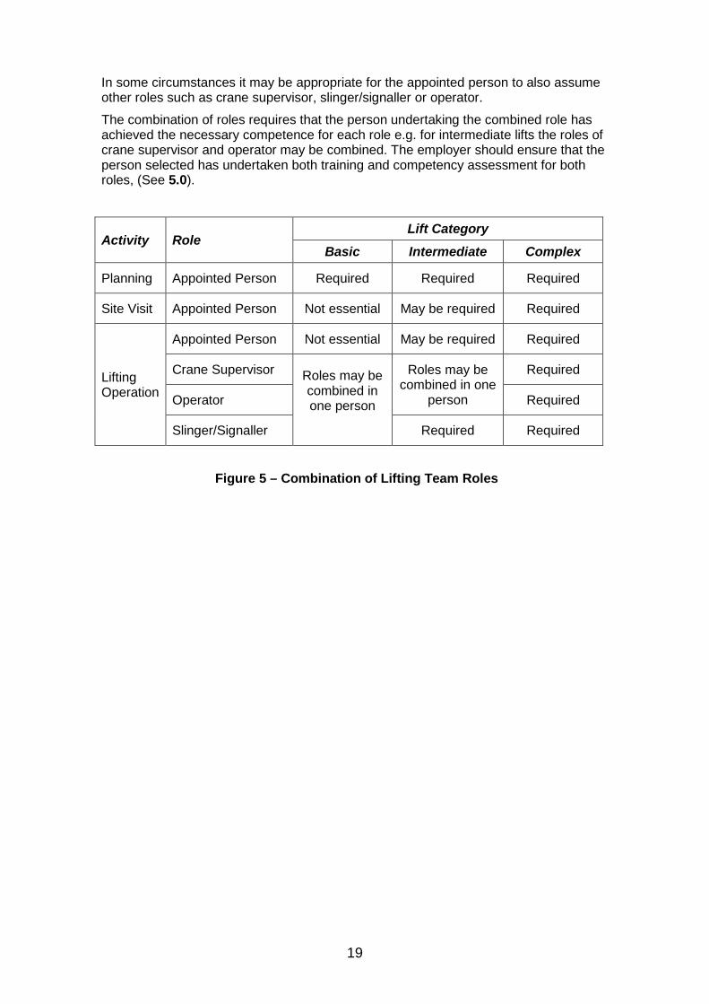
4.7 Combination of Roles In certain circumstances it may be possible to combine some of the roles of members of the lifting team. Figure 5 illustrates where this may take place, however the table should not be taken as definitive for every circumstance. Role combination should only take place following review of the lifting operation by the appointed person.
It should be noted that an appointed person is required to plan all lifting operations but need not be present during the lifting operation, except for complex lifts.
Appointed Person Lifting Operations
Crane Co-ordinator
Tower Crane 2
Crane Supervisor
Tower Crane 2 Crane Operator Slinger/Signaller
Tower Crane 2 Lifting Team
Tower Crane 1
Crane Supervisor
Tower Crane 1 Crane Operator Slinger/Signaller
Tower Crane 1 Lifting Team
Tower Crane 2
Crane Supervisor
Tower Crane 2 Crane Operator Slinger/Signaller
Mobile Crane 1 Lifting Team
19
In some circumstances it may be appropriate for the appointed person to also assume other roles such as crane supervisor, slinger/signaller or operator.
The combination of roles requires that the person undertaking the combined role has achieved the necessary competence for each role e.g. for intermediate lifts the roles of crane supervisor and operator may be combined. The employer should ensure that the person selected has undertaken both training and competency assessment for both roles, (See 5.0).
Activity Role Lift Category
Basic Intermediate Complex
Planning Appointed Person Required Required Required
Site Visit Appointed Person Not essential May be required Required
Lifting Operation
Appointed Person Not essential May be required Required
Crane Supervisor Roles may be combined in one person
Roles may be combined in one
person
Required
Operator Required
Slinger/Signaller Required Required
Figure 5 – Combination of Lifting Team Roles
20
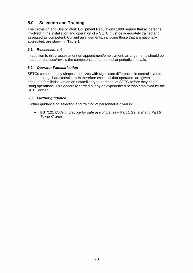
5.0 Selection and Training The Provision and Use of Work Equipment Regulations 1998 require that all persons involved in the installation and operation of a SETC must be adequately trained and assessed as competent. Current arrangements, including those that are nationally accredited, are shown in Table 1.
5.1 Reassessment In addition to initial assessment on appointment/employment, arrangements should be made to reassess/review the competence of personnel at periodic intervals.
5.2 Operator Familiarisation SETCs come in many shapes and sizes with significant differences in control layouts and operating characteristics. It is therefore essential that operators are given adequate familiarisation on an unfamiliar type or model of SETC before they begin lifting operations. This generally carried out by an experienced person employed by the SETC owner.
5.3 Further guidance Further guidance on selection and training of personnel is given in:
• BS 7121 Code of practice for safe use of cranes – Part 1 General and Part 5 Tower Cranes;
21
Activity Provided By Qualification
Slinger CPCS Accredited Training Provider CPCS Scheme Category A40
Signaller CPCS Accredited Training Provider CPCS Scheme Category A40
SETC Operators CPCS Accredited Training Provider CPCS Scheme Category A63
Additional training required for operating from cab
CPCS Scheme Category A04A or A04B
Configuration (erect & dismantle)
Crane manufacturer to crane owner for each model of SETC
In-house assessment by a competent assessor
Partial reconfiguration on site (folding jib and/or mast)
Crane owner to operator for each model of SETC
In-house assessment by a competent assessor
Maintenance Crane manufacturer to crane owner for each model of SETC
In-house assessment by a competent assessor
Instructor providing operator familiarisation
CPCS Accredited Training Provider CPCS Scheme Category A63
Crane manufacturer to crane owner for each model of SETC
In-house assessment by a competent assessor
Additional training required for operating from cab
CPCS Scheme Category A04A or A04B
Operator familiarisation
Crane owner to operator for each model of SETC
In-house assessment by a competent assessor
Crane Co-odinator In house training In-house assessment by a competent assessor
Crane Supervisor CPCS Accredited Training Provider CPCS Scheme Category A62
Appointed Person CPCS Accredited Training Provider CPCS Scheme Category A61
Site survey -fundamental
Crane owner to representative In-house assessment by a competent assessor
Site survey -familiarisation
Crane owner to representative for each model of SETC
In-house assessment by a competent assessor
Information on accredited training providers can be obtained from the Construction Plant Certification Scheme Help Desk on 0870 417 7274 or www.citb.co.uk/cardschemes/cpcs
Table 1 – Current Training Arrangements
22
6.0 Siting of SETCs The area in which a SETC is to be sited must be carefully assessed to ensure that it is suitable before the crane is taken to site and put into service. During this assessment, the following points should be considered.
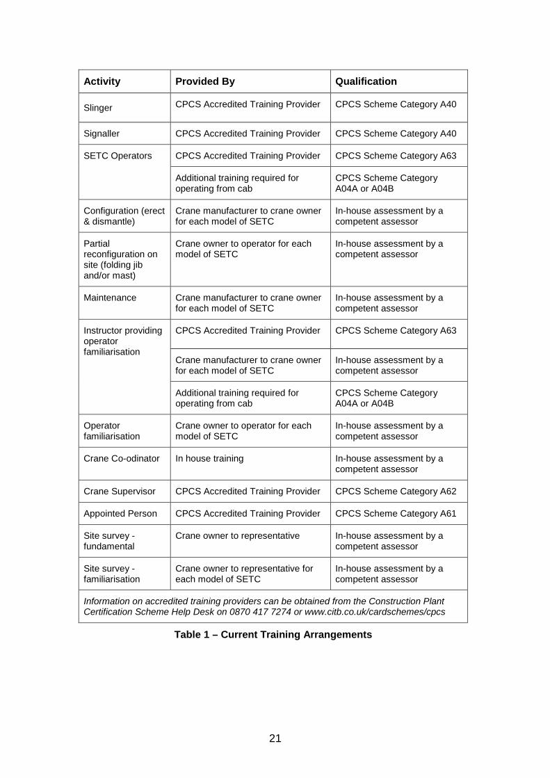
6.1 Clearances The area chosen must be of a sufficient size to enable the SETC to be manoeuvred into position, set up, operated and dismantled, with sufficient clearances between the crane and surrounding structures, as detailed in the manufacture’s operation and instruction manual. This is to ensure that trapping points are not created and that damage does not occur to either the crane or the surrounding structures (including the building under construction). The Guidance to LOLER specifies a minimum gap for areas into which persons may enter of 0.6m. Fencing or barriers should be erected around the base of cranes to restrict access to pedestrians or damage from workplace transport moving in the immediate vicinity. Entry to the area should be controlled by a safe system of work (See Figure 6)
Figure 6 - Unprotected and Protected Base of a SETC
6.2 Ground conditions
Insufficient consideration and assessment of ground conditions has been found to be a major cause of accidents with SETCs.
All SETCs rely for their stability on the ability of the ground on which they are standing to safely absorb the loads imposed by the crane. Most SETC manufacturers supply information on the loads imposed by the crane on the ground in the various operating and set up configurations of the crane. These generally consist of :-
• Maximum vertical load per stabiliser;
• Maximum horizontal reactions;
• Dimensions of stabiliser support plate (pad);
• Ground-level pressure under stabiliser support plate.
An assessment of the ability of the ground to accept these loads should be made by a competent person. This assessment may indicate that the ground has insufficient bearing capacity to accept the loads imposed by the crane, in which case additional measures will need to be taken before the crane can be set up. These may include using timber sleepers, proprietary mats or concrete pads to spread the applied
23
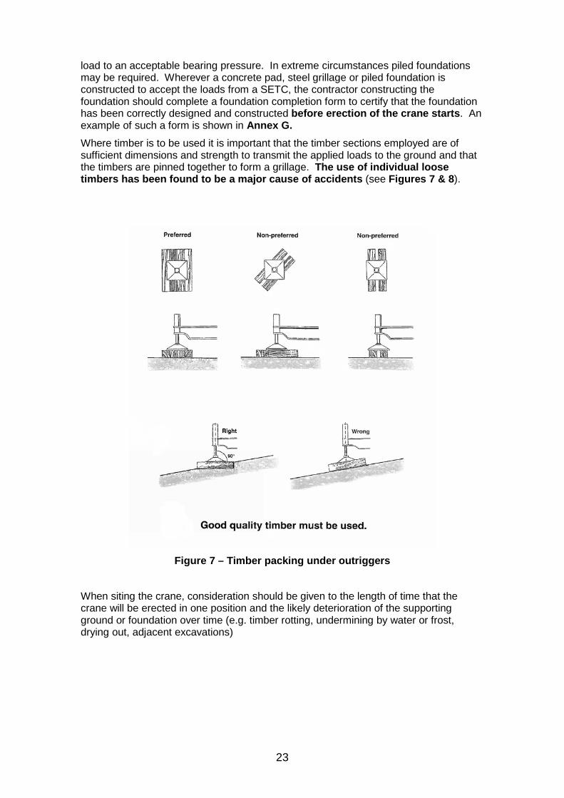
load to an acceptable bearing pressure. In extreme circumstances piled foundations may be required. Wherever a concrete pad, steel grillage or piled foundation is constructed to accept the loads from a SETC, the contractor constructing the foundation should complete a foundation completion form to certify that the foundation has been correctly designed and constructed before erection of the crane starts. An example of such a form is shown in Annex G. Where timber is to be used it is important that the timber sections employed are of sufficient dimensions and strength to transmit the applied loads to the ground and that the timbers are pinned together to form a grillage. The use of individual loose timbers has been found to be a major cause of accidents (see Figures 7 & 8).
Figure 7 – Timber packing under outriggers
When siting the crane, consideration should be given to the length of time that the crane will be erected in one position and the likely deterioration of the supporting ground or foundation over time (e.g. timber rotting, undermining by water or frost, drying out, adjacent excavations)
24
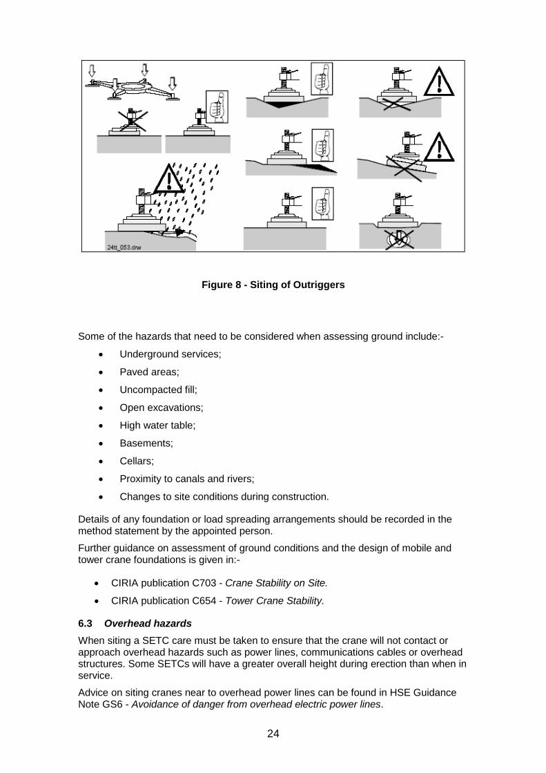
Figure 8 - Siting of Outriggers
Some of the hazards that need to be considered when assessing ground include:-
• Underground services;
• Paved areas;
• Uncompacted fill;
• Open excavations;
• High water table;
• Basements;
• Cellars;
• Proximity to canals and rivers;
• Changes to site conditions during construction.
Details of any foundation or load spreading arrangements should be recorded in the method statement by the appointed person.
Further guidance on assessment of ground conditions and the design of mobile and tower crane foundations is given in:-
• CIRIA publication C703 - Crane Stability on Site.
• CIRIA publication C654 - Tower Crane Stability.
6.3 Overhead hazards When siting a SETC care must be taken to ensure that the crane will not contact or approach overhead hazards such as power lines, communications cables or overhead structures. Some SETCs will have a greater overall height during erection than when in service.
Advice on siting cranes near to overhead power lines can be found in HSE Guidance Note GS6 - Avoidance of danger from overhead electric power lines.
25
6.4 Proximity to railways and airports If the SETC is to be sited adjacent to a railway or in the vicinity of an airfield or airport the appointed person should contact the operator of the facility as they may well impose restrictions on the height, lifting capacity and use of the crane.
Further guidance on the use of cranes in the vicinity of airfields is given in:-
• Cranes and planes - A guide to procedures for operation of cranes in the vicinity of aerodromes. Airport Operators Association (AOA).
• A voluntary code of practice for the safe use of cranes in and around airports. Off-highway Plant and Equipment Research Centre.
6.5 Oversailing adjacent property If the siting of the crane will result in oversailing of an adjacent property not in control of the Principal Contractor, oversailing rights must be obtained in advance by the Principal Contractor (hirer). Consideration needs to be given to inadvertent oversailing whilst the crane is left, when not in use, in free slew. Should the crane need to be guyed, tethered or the slew locked, when out of service this must be considered at the initial planning stage and foundation loads for the specific configuration obtained from the manufacturer. This information must be provided to the hirer and included in both the erection and use method statements. Cranes should not be left in a part erected condition overnight ( i.e. jib partially folded back) unless allowed for in the manufacturer’s manual or without prior written approval from the crane manufacturer.
A self erecting tower crane was erected on a site adjacent to a row of occupied houses. Over the first weekend the occupants of the houses became alarmed when the crane, which had been left in free slew, moved over their houses. Their concern was heightened by the presence of a generator slung from the hook. A complaint to the Health and Safety Executive resulted in a prohibition notice being served on the construction company.
Where the crane’s jib and/or mast is to be folded to avoid oversailing when out of service the operator must be competent to carry out this procedure (see 5.0). The maintenance schedule for the crane will need to be adjusted accordingly. (See 11)
6.6 Access & egress to and from the site It is important when siting a SETC to ensure that there is adequate access to the crane position for both the SETC and any supporting transport. It is equally important to assess egress with regard to removing the crane from site. It has been known for a building to be constructed around a crane, making it extremely difficult and costly to remove at the end of the job!
A self erecting tower crane was being used for lifting on a refurbishment project in a town centre. The crane stood in a courtyard for the duration of the project and the only way in to the courtyard was through a single archway, which was just high enough to allow the folded SETC to pass below. During construction a beam was inserted at the top of the arch to support a wall being constructed above. When it was time to remove the crane from site it was found that the headroom had been reduced to such an extent that the crane could not pass through the archway. The only way to remove the crane was to dismantle it at considerable cost and inconvenience to the site.
26
6.7 Power supply
Before the SETC arrives on site, checks should be made to ensure that there is an adequate mains electricity supply. Larger SETCs require a three phase supply, whilst smaller cranes can run on a single phase supply. The SETC manufacturer’s instruction manual will specify the type and size of supply required. If a suitable mains supply is not available on site, the alternative is to use an engine driven generator which must be adequately earthed and sized to cope with the potentially high starting currents of the SETC motors. The use of frequency controlled motors on later designs of crane will reduce starting currents and consequently the capacity of the power supply, which is particularly beneficial when a generator is used. Some control systems however, require that the power supply to the control panel heaters is left on at all times to ensure to maintain a stable temperature. In this case, when power from a generator is not available, a temporary night supply will be required.
All cables should be of the steel wire armoured type to give adequate mechanical protection in site conditions. The power supply should terminate in a suitable weatherproof isolator adjacent to the crane. If earth fault protection is provided by the use of Residual Current Devices (RCDs) these may need to be set with higher trip current and delay setting than normal (typically 100mA and 5s), to prevent nuisance tripping caused by frequency control drives on the SETC. RCDs with a 30mA rated tripping current are only required on final sub circuits such as socket outlets.
The electrical installation should be in accordance with BS 7671:2008 Requirements for electrical installations — IEE Wiring Regulations 17th edition.
Further guidance on the electrical safety on construction sites is given in:-
• HSE Guidance document HS(G) 141 Electrical safety on construction sites.
6.8 Wind The crane supplier/manufacturer will be able to advise on the maximum in-service and out of service wind conditions for the specific model of crane to be used. The out of service wind loadings will often be much greater than the in-service loads and the load bearing capability of the ground (foundation) must be sufficient for the extra imposed loads due to out-of-service wind. Where the SETC is to be taken down when high winds are anticipated, the operator must be made aware of any wind speed restrictions for dismantling.
There have been a number of accidents where the ground conditions were not suitable for the out of service loadings or SETC have been dismantled at wind speeds in excess of the manufacturers maximum recommended speeds.
SETC’s should be left in free slew when out of service to allow the crane to “weathervane”, to ensure that the out of service foundation loads are not exceeded.
The Approved Code of Practice to LOLER says that “Where lifting equipment, and/or its load, may be affected by high wind the equipment should be fitted with appropriate devices so as to detect dangerous situations and allow measures to be taken to cease using the equipment”. Consequently all SETCs should be fitted with an anemometer (many new cranes are now supplied with an anemometer as a standard fitting). A record of wind speed monitoring should be kept and electronic wind recording systems are now available for this task.
All operating personnel should be aware of wind speed action levels for the particular crane in use. It is important to note that the maximum wind speed at which the jib of a SETC can be safely folded back is often lower that the maximum in-service wind speed. Ignoring this has led to a number of accidents. (See 7.8)
Further advice on wind on tower cranes, both in and out of service, is given in TIN 020 and TIN 025
27
NOTE: The normal design limiting in-service wind speed for tower cranes is 45 mph (20 m/s, 72 kph). Following a review of in-service wind speeds by the CPA Tower Crane Interest Group, involving tower crane suppliers, major contractors and the Health and Safety Executive, the industry recommended maximum wind speed at which tower cranes operating in the UK must be taken out of service is 38 mph (16.5 m/s, 60 kph).
6.9 Lightning Protection When a SETC is to left erected on a site for a period of time, consideration should be made to providing lightning protection. Reliance should not be placed on the earth conductor of any mains power supply. Normally the earth bonding can be connected to the lowest metallic part of the crane structure as the metal structure of a SETC provides good continuity. To ensure an adequate earth is achieved the resistance path between the bottom of the tower and earth should be measured and should not exceed a value of 10 Ω.
If the resistance to earth exceeds 10Ω, the SETC base should be bonded to a suitable earth network via a single core cable of not less than 70 mm2 cross sectional area and the earth resistance measured again to ensure that it has been reduced to an acceptable value.
In the event of a lightning strike the SETC should be thoroughly examined before being returned to service, to ensure that damage has not occurred to the crane or any of its components including the slew ring, safety and control systems. NOTE: Lightning protection is normally carried out by the user as part of the power supply provision.
6.10 Floodlights It is not recommended that SETC are used for mounting flood lights unless both the lights and installation are approved by the crane manufacturer.
6.11 Zoning systems Some SETCs are fitted with working space limiters or “zoning devices”. These prevent the load and/or parts of the crane from entering a prohibited place such as a railway line. NOTE: Zoning systems should be subjected to daily function checks before lifting operations are started. NOTE: The appointed person should periodically confirm and check that the zoning systems are both functional and sufficient.
6.12 Radio communication systems SETCs often work on congested construction sites where the signaller is out of sight of the SETC operator and the standard hand signals specified in BS 7121 cannot be used. As an alternative, hand held VHF/UHF radios are often used. This however, can lead to a number of problems which may interfere with the clear communication vital for safe lifting operations:-
• Loss of signal and thus communication, leading to loss of control of the lifting operation;
• Interference from radios on adjacent sites, which can lead to loss of communication or directions being given to the wrong SETC operator;
• Misunderstanding between the SETC operator and the signaller, leading to problems such as a load being lifted before the slinger has his hands clear, loads colliding with the building structure and the load being lowered before people are clear of the landing area.
28
Further details on radio communications, including call signs and standard commands are given in Annex J (TIN 017).
6.13 Scale drawing Where a mobile crane is to be used for installation or removal the crane owner’s appointed person should prepare, or have drawn up under his direction, a scale drawing of the site. The drawing should include the following information:-
• Plan and side elevation views;
• Outline envelope of the building under construction;
• The planned location of the mobile crane with dimensions to reference points to aid location;
• The make and model of crane selected;
• The radius that the crane can reach;
• SWL at max radius;
• Height under hook;
• Outrigger loadings;
• Proximity hazards and delivery vehicle unloading areas.
6.14 Further guidance Further detailed guidance on the siting of cranes is given in:
• BS 7121 Code of practice for safe use of cranes – Part 1 General and Part 5 Tower Cranes.
• CIRIA publication C654 - Tower Crane Stability. • CIRIA publication C703 - Crane Stability on Site.
29
7.0 SETC Operation
SETCs should be operated by operators who have been trained and assessed as competent (see Sections 4 & 5). NOTE: Where SETCs are to be operated from a cab, the operator will require additional training (see Section 5).
7.1 Manuals and Signs All operations should be carried out in accordance with the manufacturer’s operating instruction manual, a copy of which should be with the crane at all times. Checks should be made by the supplier to ensure that the manual :-
• Has been left with a responsible person on site;
• Is the correct manual for the crane supplied;
• Conveys information to the users in a simple and understandable format and is in a language (normally English) that is readily understood by the operator.
All signs labels and decals on the crane must be in a language (normally English) that is readily understood by the operator.
7.2 Slinging, Signalling and Crane Operation The operator of a pedestrian operated SETC has some flexibility in where he stands and may be able to take on some of the responsibilities normally undertaken by a signaller. He should however, not normally take on the additional role as the slinger. Combining the roles of slinging, signalling and crane operation requires very careful planning See 4.7.
7.3 Pedestrian Crane Operation The operation of SETCs is frequently carried out by a pedestrian operator at ground level, using remote controls that may be hard wired or use a wireless data transmission system. Whilst pedestrian control provides flexibility with the possible combination of roles (see 7.2) there are several potential disadvantages that must be taken into account in planning the lifting operations:-
• The crane operator may well be at risk of tripping and falling when trying to move around the site over uneven ground whilst concentrating on controlling the crane. Pedestrian operated SETCs should only be controlled whilst the operator is stationary;
• The crane operator has no feel for the machine and could, under certain circumstances, be tempted to handle the machine more roughly than if the crane were operated via a cabin control;
• The operator may not have a good view of the load and any obstructions, consequently the operator must always have the crane jib and load in sight at all times;
• Infra-red remote control can be unreliable on SETCs if the receiving sensor rotates with the crane and thus loses alignment with the transmitter.
7.4 Wireless Controls To prevent unauthorized use, the operator of a SETC that is controlled by transmitted signals, such as radio signals, should retain the control station (transmitter) in their physical possession or remove the key from its key-lock switch and, for short periods, retain the key in their possession. For longer periods, or when the crane is not in use, the transmitter should be kept in secure storage.
30
When the control station (transmitter) is fitted with a belt or harness, the operator should be wearing the harness before switching on the controls so that accidental operation of the crane is prevented. The control station (transmitter) should only be switched on when operating the crane and should be switched off before removing the harness.
The design of controls and shrouding should comply with BS EN 13557:2003 – Cranes – Controls and control stations to prevent inadvertent operation. Wireless controls should be fitted with a warning signal of the approach to the rated capacity as required by BS EN 14439:2006 Cranes – Tower cranes.
Some SETCs are provided with remote controls with reduced functionality which must only be used as a temporary measure in the event of an emergency.
Wireless controls must only be used to control one crane at one time.
SETCs controlled by wireless controls must be fitted with a separate emergency stop control at the base of the crane to enable bystanders to stop the crane in an emergency, if the operator and control station are not in the immediate vicinity.
7.5 Rated Capacity The rated capacity of a SETC should not be exceeded, except when testing the crane under the supervision of a competent person. If the crane is fitted with supplementary RCI indicators take care not to obstruct them from view.
The RCI audible alarm should be checked to ensure that it is audible and discernable above background noise within the operating radius of the crane.
Care should be taken to prevent pendulum swinging of the load, by careful control of the operating motions to match the swing of the load and to keep it under control at all times.
Rated capacities apply only to freely suspended loads. The hoisting, slewing, traversing, luffing or travelling motions of a crane should not be used to drag any load along the ground with the hoist rope out of the vertical position. Before lifting a load, the hoist line should be plumb. Failure to observe these points can adversely affect the stability of the crane or introduce loadings (stresses) into the crane for which it has not been designed and, even with a rated capacity indicator/limiter fitted, a sudden failure can occur. Tag lines should be attached to loads where movement of the load during the lifting operation may be hazardous. Further guidance in the use of tag lines is given in TIN 020.
A site with two top slew tower cranes requested that they be fitted with wireless remote controls. This enabled the contractor to save money by allowing one operator to operate both cranes whilst sitting in the cab of one of them. Inevitably this led to an incident where a load on the hook of the remote crane became entangled with scaffolding, when the operator’s view was obscured.
31
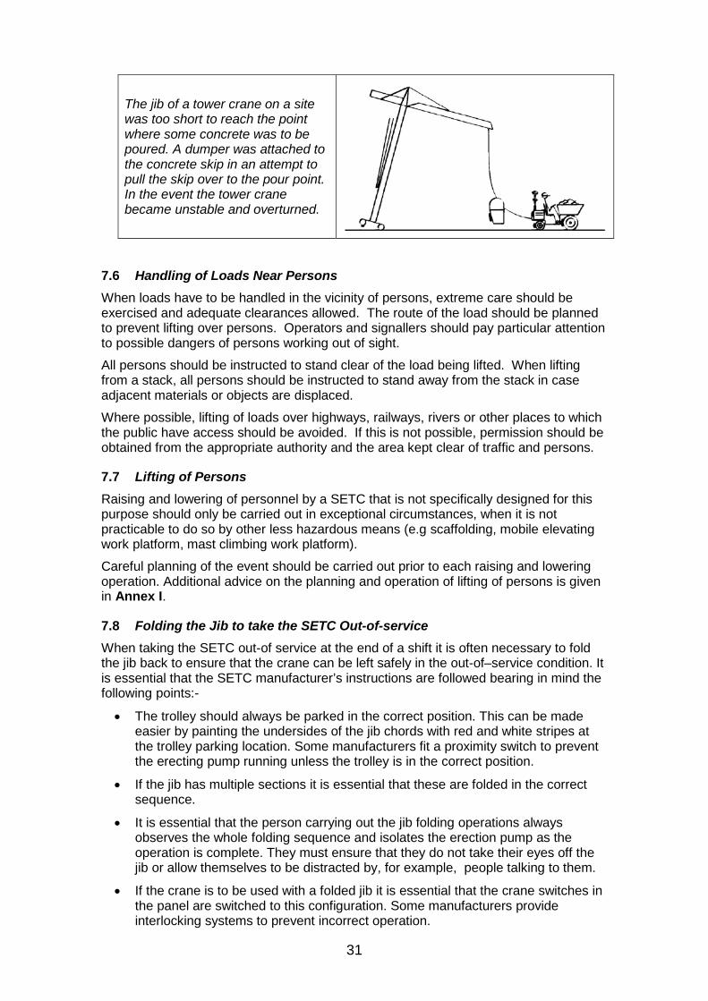
The jib of a tower crane on a site was too short to reach the point where some concrete was to be poured. A dumper was attached to the concrete skip in an attempt to pull the skip over to the pour point. In the event the tower crane became unstable and overturned.
7.6 Handling of Loads Near Persons When loads have to be handled in the vicinity of persons, extreme care should be exercised and adequate clearances allowed. The route of the load should be planned to prevent lifting over persons. Operators and signallers should pay particular attention to possible dangers of persons working out of sight.
All persons should be instructed to stand clear of the load being lifted. When lifting from a stack, all persons should be instructed to stand away from the stack in case adjacent materials or objects are displaced.
Where possible, lifting of loads over highways, railways, rivers or other places to which the public have access should be avoided. If this is not possible, permission should be obtained from the appropriate authority and the area kept clear of traffic and persons.
7.7 Lifting of Persons Raising and lowering of personnel by a SETC that is not specifically designed for this purpose should only be carried out in exceptional circumstances, when it is not practicable to do so by other less hazardous means (e.g scaffolding, mobile elevating work platform, mast climbing work platform).
Careful planning of the event should be carried out prior to each raising and lowering operation. Additional advice on the planning and operation of lifting of persons is given in Annex I.
7.8 Folding the Jib to take the SETC Out-of-service When taking the SETC out-of service at the end of a shift it is often necessary to fold the jib back to ensure that the crane can be left safely in the out-of–service condition. It is essential that the SETC manufacturer’s instructions are followed bearing in mind the following points:-
• The trolley should always be parked in the correct position. This can be made easier by painting the undersides of the jib chords with red and white stripes at the trolley parking location. Some manufacturers fit a proximity switch to prevent the erecting pump running unless the trolley is in the correct position.
• If the jib has multiple sections it is essential that these are folded in the correct sequence.
• It is essential that the person carrying out the jib folding operations always observes the whole folding sequence and isolates the erection pump as the operation is complete. They must ensure that they do not take their eyes off the jib or allow themselves to be distracted by, for example, people talking to them.
• If the crane is to be used with a folded jib it is essential that the crane switches in the panel are switched to this configuration. Some manufacturers provide interlocking systems to prevent incorrect operation.
32
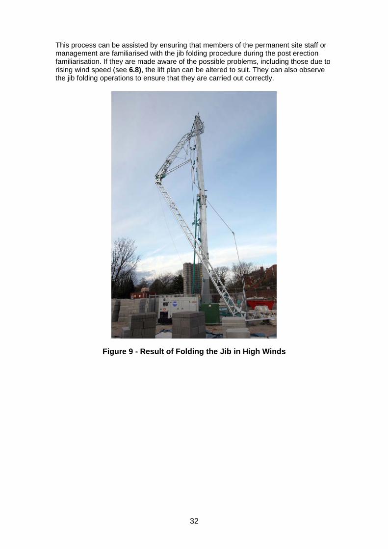
This process can be assisted by ensuring that members of the permanent site staff or management are familiarised with the jib folding procedure during the post erection familiarisation. If they are made aware of the possible problems, including those due to rising wind speed (see 6.8), the lift plan can be altered to suit. They can also observe the jib folding operations to ensure that they are carried out correctly.
Figure 9 - Result of Folding the Jib in High Winds
33
8.0 Lifting Accessories
In preparing the method statement (lift plan) consideration should be made to the selection of lifting accessories such as wire rope slings, chains slings, webbing slings and shackles to ensure that they are sized for the anticipated loads to be handled.
All the lifting accessories on a site should be listed in a lifting accessory register (see Annex E).
The following points should be considered when selecting lifting accessories:-
• Lifting accessories should be supplied with a current report of thorough examination;
• The secure storage of lifting accessories when not in use should be considered at the planning stage and suitable arrangements made;
• Lifting accessories should be protected with protective sleeves or suitable packing, where loads with sharp edges are to be lifted;
• For the lifting of awkward materials or items with a non-central centre of gravity, lifting beams, spreader bars or purpose designed lifting beams may be required;
• All accessories should be marked with a Working Load Limit (Safe Working Load);
• The type, size, rating and configuration of lifting accessories to be used for each load or generic type of load to be lifted should be recorded in the method statement (lift plan);
• Before each use of lifting accessories pre-use checks should be carried out to ensure that they are in good condition and that a current report of thorough examination is available;
• LOLER requires that lifting accessories are thoroughly examined at intervals not exceeding six months.
34
9.0 Transportation to Site Including Loading, Unloading and Positioning on Site
SETCs can be transported to site in a number of ways depending on their design.
These are:-
• Carried to site on a low-loader;
• Towed to site on high speed axles;
• Towed to site on low speed axles;
• Be mounted on a road going chassis.
When towed on the road the SETC should comply with the requirements of the Road Traffic Act and the Construction and Use Regulations. Vehicles that cannot comply with the Construction and Use Regulations will need to be moved under the Motor Vehicles (Authorisation of Special Types) General Order 2003 (STGO) which requires advance notice to be given to the Police and Road & Bridge Authorities.
9.1 Transportation to site All transportation of the SETC should be planned and the method statement should include :-
• Vehicle routes, taking into account height restrictions etc;
• Parking restrictions around the site;
• Access to the site;
• Towing vehicle, if the SETC is to be towed;
• Access on site for off loading;
• Unloading of the SETC from a trailer – winch, crane etc;
• Preparation for transport - Slew lock engaged and correct configuration (prop to take load off slew ring);
• Marking of lifting points to avoid confusion with tie-down points.
9.2 Positioning on site Moving and positioning an SETC on site should be taken into account by the appointed person at the Planning stage (see Section 3) and fully detailed in the method statement.
The method statement should include:-
• Method used to position the SETC e.g. mobile crane, winch, site vehicle;
• Route to be taken on site;
• Protection of bystanders;
• Any ground preparation required of the planned route;
• Timing of operation and personnel required.
35
10.0 Erection, Alteration and Dismantling 10.1 Erection personnel Erection, alteration and dismantling procedures should be carried out by personnel, who have been trained and assessed as competent (see Sections 4 & 5), in accordance with the manufacture’s instruction manual for the specific model of SETC.
10.2 Working at height Erection, dismantling or reconfiguration of an SETC may require persons to work at height (e.g. installation of counterweights or reconfiguration of the jib). The Work at Height Regulations require that before working at height a risk assessment is made and control measures are taken to reduce the risk of a person falling and being injured. These should include the provision of fixed ladders or steps at all access points. If fall arrest systems are used a plan should be drawn up to cover the rescue of persons suspended from fall arrest equipment. Addition information on work at height is given in Annex H.
10.3 Erection The SETC should be erected in accordance with the method statement (lift plan) prepared by the appointed person (see Section 3.10). Attention should be paid to the following:-
• That a copy of the manufacture’s installation manual is available on site and is followed:
• That the crane is erected in the position shown on the site plan;
• That a foundation handover certificate (see Annex G) is provided prior to erection;
• That spreader mats and grillages to spread the outrigger loads are installed as specified by the appointed person;
• That a check is made to see if there are any new or additional hazards on the site prior to erection. The appointed person should be consulted if any significant hazards are identified and appropriate control measures agreed with the appointed person;
• That a suitable exclusion zone is established to exclude personnel from the area into which the crane or its components could fall in the event of a failure during erection;
• That after erection a full functional check on the crane should be completed and any slewing/zoning restriction systems set and tested. The functional testing should include the lifting of a test weight in accordance with the manufactures instructions. This will enable the Rated Capacity Indicator and Limiting Device to be calibrated
• That the correct functioning of the Rated Capacity Indicator and Limiting Device is tested;
• That a thorough examination (if required See 12.1) is carried out after erection and that a report of thorough examination is completed;
• That following erection a handover sheet should be completed and signed by the erector and handed to the user (employing organisation);
36
A SETC was being used to construct a four storey building on a congested site. As the building increased in height the jib was luffed to enable the crane to reach over the pitched roof under construction. Unfortunately during re-rigging the selector switch in the control panel was not reset for the new duty and the crane was used in the new configuration to lift a pack of timber onto the roof. The operator was able to hoist and trolley out the load, but when he put the trolley control in neutral the brake was not able to hold the trolley on the inclined jib and the trolley, with the load, moved down the jib until it reached the mast. As the load rotated and hit the mast, the timbers broke loose from the pack with individual lengths falling like javelins to the ground below. Although the operator was severely shaken, fortunately no one was hurt.
If the selector switch had been correctly reset for the new duty, the lifting capacity of the crane would have been reduced to compensate for the increased loading placed on the trolley motor by the inclined jib and the accident avoided.
• That the owner of the crane should familiarise the user’s trained operators with
the controls, functions and limitations of the specific SETC before it is taken into use;
• Ballast weights of SETCs are often made from precast reinforced concrete. Checks should be made, before lifting the weights into place, that the weights are not damaged and that the lifting points are in good condition.
10.4 Dismantling The SETC should be dismantled in accordance with the manufacture’s instructions and the method statement prepared by the appointed person (see Section 3.10). Attention should be paid to the following:-
• That a copy of the manufacture’s installation manual is available on site and is followed;
• That the wind speed is within the limits specified by the SETC manufacturer and is steady or falling. Dismantling should not be started with a rising wind speed;
• That before starting dismantling the crane is still erected in the position shown on the site plan;
• That spreader mats and grillages to spread the outrigger loads are still installed as specified by the appointed person;
• That the ballast is still installed as specified in the manufacturer’s manual;
• That a check is made to see if there are any new or additional hazards on the site prior to dismantling. Particular attention should be paid to ensuring that sufficient space is available for the jib/mast assembly to be lowered. The appointed person should be consulted if any significant hazards are identified and appropriate control measures agreed with the appointed person;
• That a suitable exclusion zone is established to exclude personnel from the area into which the crane or its components could fall in the event of a failure during dismantling;
• That before dismantling a full functional check on the crane should be completed and the slew brake/pins set according to the manufacturer’s instructions.
37
• Care should be taken that any outrigger jacks are retracted evenly to prevent the crane becoming unstable;
• Ballast weights of SETCs are often made from precast reinforced concrete. Checks should be made before lifting the weights that the weights are not damaged and that the lifting points are in good condition. After removal the weights should be stacked correctly in a safe location.
A SETC was being dismantled to a point where the mast and jib had been stowed. The erection team were in the process of retracting the outriggers. Unfortunately the crane had been left in free slew and as the superstructure tilted it swung round severely crushing one of the erectors against the newly constructed building.
Had the manufacturer’s instructions been followed the accident could have been prevented.
10.5 Further guidance Further detailed guidance on the erection, alteration and dismantling of tower cranes is given in :-
• BS 7121 Code of practice for safe use of cranes – Part 5: Tower cranes.
• CIRIA publication C654 - Tower Crane Stability.
38
11.0 Checks, Inspections and Maintenance The effective maintenance of a SETC is an essential part of safe operation. As with all lifting machines, the SETC wears and deteriorates over time and the maintenance process, including checks and inspections, both monitors, prevents and rectifies this deterioration. It is important that the personnel asked to carry out these tasks have the necessary machine-specific training, experience and competence in both periodic and breakdown maintenance.
SETCs are complex machines with electrical, mechanical and hydraulic systems that require the manufacturer’s preventative maintenance instructions to be strictly complied with, if safety is to be maintained in use. Checks and inspections should be carried out taking account of the frequency of use of the SETC and the environmental conditions in which it regularly works. If the operator is considered to be competent, they may be authorized to carry out routine pre-use and weekly checks.
The employer of the person carrying out these checks should ensure that the machine is taken out of use for the period of time required to carry them out. Also, the employer or authorized person carrying out the checks should ensure that a safe system of work is in place to prevent personnel from being exposed to risk, for example from the inadvertent operation of the equipment.
It is essential that the base of the SETC is well drained and kept free of obstructions that would impede access for checks and inspections.
Detailed guidance on the maintenance, inspection and thorough examination of tower cranes is given in the CPA Best Practice Guide on the Maintenance, Inspection and Thorough Examination of Tower Cranes. This publication may be downloaded without charge from the CPA website
A SETC was placed on a site where conditions dictated that the crane was erected and dismantled on a daily basis. The maintenance schedule for the crane was not adjusted to take account of the high frequency of erection and dismantling, and the pinned joints on the folding jib were not greased at sufficient frequency. During a Thorough Examination excessive wear on the pins and joints was discovered and the crane was taken out of service. This resulted in considerable down time, delay to the site and expense which could have been easily avoided by revision of the lubrication schedule.
11.1 Daily pre-use checks At the beginning of each shift or working day before work commences, the following visual and functional routine checks, if appropriate for the type of SETC, should be carried out :-
• Checks as required by the manufacturer’s handbook;
• Cleanliness and general signs of damage;
• Lubrication as required by the manufacture’s handbook;
• Visual check of the ground supporting the base;
• Visual check of packers/grillages;
• Visual check that the base is level;
• Visual check of the chassis and outriggers;
• Visual check of base fencing;
• Visual check of the condition of the power supply cable;
39
• Visual check of wire ropes, anchorages and hook block;
• Check of the wire rope spooling on the winch drums;
• If fitted, check levels of the engine cooling-water and lubricating oil;
• Visual check of security of any pin locating arrangements and for visible damage to the structure;
• No load operation of the crane motions to check correct functioning of motors and brakes and for movement under outriggers during slewing;
• Check for correct functioning of controls and safety devices.
A record of the daily check should be kept (for example on a timesheet) and a defect reporting system should be in place so that any defects are rectified promptly. NOTE: Where there are multiple operators for one crane, a system should be put in place to ensure that one person is responsible for carrying out the pre use checks.
11.2 Intermediate (weekly) inspections The intermediate inspections listed should either be carried out once a week or at intervals recommended by the manufacturer. These inspections are in addition to the daily pre-use checks and are to ensure that all systems function correctly, that the SETC is free from damage and that fluid levels are within the manufacturer’s limits. Inspections should be appropriate for the type of SETC and include the following :-
• Inspections as required by the manufacturer’s handbook;
• All structural parts should be sound and free from visible defects. The structure should be inspected for damage, loose or missing retaining pins, damaged hoses and wiring, and any loose or missing fittings;
• Hydraulic systems (if fitted) should be free from leaks;
• Hydraulic fluid levels should be checked where accessible;
• The base structure, including any safety guards, should be free of damage and clear of debris;
• The crane base should be level. Any stabiliser support plates should be firmly founded, the screw jacks in good condition and locked;
• All engine, water, oil and fuel levels should be checked and topped up where necessary;
• All hoses, fittings, wiring and valves etc. should be inspected for leaks, security and damage;
• Any emergency lowering and slewing equipment fitted should be tested;
• All operating and warning decals should be clear and readable;
• All controls, including any emergency systems, should be tested;
• Drive systems, brakes, steering and speed controls should all be tested for correct operation;
• The correct operation of the Rated Capacity Limiter should be checked;
• The operation of limit switches should be checked by carefully carrying out load-free manoeuvres at all speeds;
• The condition of the hook and latch should be checked;
• Wire ropes on the accessible area of the crane should be checked for lubrication, wear and damage;
• Automatic lubrication systems should be checked for correct functioning.
40
12.0 Thorough Examination The Lifting Operations and Lifting Equipment Regulations 1998 (LOLER) require that all lifting equipment, including SETCs, is thoroughly examined by a competent person in the following circumstances:-
• At regular intervals (a period not exceeding 12 months, if persons are not lifted, or 6 months if persons are lifted);
• After erection on a new site;
• After any major alteration or damage (event).
It is however good practice to set the maximum interval for all tower cranes (including SETCs) on construction sites at six months for the following reasons:-
• Tower cranes frequently work above or near people, both personnel on site and members of the public outside the site;
• The intensity of use and the environment in which they are installed.
This decision may be made by the competent person or the tower crane owner.
Top slew tower cranes are invariably erected on site from a selection of components and must therefore be thoroughly examined after erection and before they are taken into use. They are then thoroughly examined at the appropriate periodic intervals for as long as they remain on that site. Thorough examination is also required when any alteration is made to the crane’s structure or configuration.
12.1 Thorough Examination of SETCs The requirement for thorough examination of SETCs will depend on the extent of assembly from components carried out during the deployment of the crane on site. In the case where a SETC arrives at site, is positioned on a prepared base, connected to a power supply, deployed by unfolding with its own winches and where no additional components are put into the structure; then no thorough examination following erection will be required as the crane will not have materially altered since its last periodic examination. A parallel may be drawn here with mobile cranes.
On the other hand a SETC where after delivery to site and positioning on a prepared base, the deployment of the crane structure requires the assembly of additional components will require a thorough examination after erection as is the case with a top slew tower crane.
In either case checks should be carried out on site after installation to ensure that all crane motions and limits are functioning correctly.
12.2 Thorough Examination of Lifting Accessories LOLER requires that lifting accessories are thoroughly examined at intervals not exceeding six months.
12.3 Further guidance Further detailed guidance on the thorough examination of cranes is given in:-
• Best Practice Guide on the Maintenance, Inspection and Thorough Examination of Tower Cranes, 2008 – Construction Plant-hire Association.
• BS 7121 Code of practice for safe use of cranes – Part 2: Inspection, testing and examination.
• L113 Safe Use of Lifting Equipment - Lifting Operations and Lifting Equipment Regulations 1998 Code of Practice - ISBN 0 7176 1628 2
41
Annex A – Definitions appointed person person with the training, practical and theoretical knowledge and experience required to comply with 3.0
crane coordinator person who plans and directs the sequence of operations of cranes (including lorry loaders) to ensure that they do not collide with other cranes, loads and other plant (e.g. concrete placing booms, telehandlers, piling rigs)
crane operator person who is operating the crane for the purpose of positioning loads (or erection of the crane) NOTE: Sometimes referred to as “crane driver”.
crane supervisor person who controls the lifting operation, and ensures that it is carried out in accordance with the appointed person’s safe system of work
employing organization person or organization who requires a lifting operation to be carried out and is responsible for safe use of the crane NOTE: In the case of a hired crane the degree of the employing organization’s responsibility for the safe use of the crane will depend on whether the crane is being supplied under a crane hire contract or a part of a contract lift See 2.0
lifting any movement of loads or persons that includes a change of height
lifting accessory equipment from which the load can be suspended
lift plan see method statement
lifts
basic lift lifting operation where the weight of the load(s) can be simply established, and there are no significant hazards within the working area or on the access route to the working area
intermediate lift lifting operation where there are significant hazards, either within the working area of the SETC or on the access route to the working area NOTE: Formally known as a “standard lift”.
42
complex lift lifting operation where the SETC is used to lift complex loads or persons, where two or more SETCs are used to lift the load or where the lifting operation is carried out at a location with exceptional hazards NOTE: An example of a location with exceptional hazards is a chemical plant.
load weight which is lifted by the crane NOTE: If cranes are used to lift loads from water, the load could also include forces due to water flow or suction.
method statement document produced by the appointed person to describe how the crane installation or lifting operation should be carried out NOTE: The appointed person may delegate the task of preparing the method statement to another person however they retain responsibility for the method statement. It is essential that the appointed person sign and date the document before it is issued for use to signify their approval of the method statement’s content.
truck mounted tower crane self-erecting tower crane permanently mounted on a road-going chassis
pedestrian operated tower crane a tower crane of any type (top slew or self erecting) which is controlled by an operator standing at a position not on the crane structure using a hard wire or wireless (cableless) control station. NOTE: The CPCS training category A63 limits pedestrian operated tower cranes to a maximum of 36m - 100metre-tonne
rated capacity load that the crane is designed to lift for a given operating condition (e.g. configuration, position of the load) NOTE: The rated capacity was formerly known as “safe working load”.
self-erecting tower crane (SETC) slewing jib type crane with jib located at the top of a vertical tower which is a pre-assembled unit transported to site and deployed from its travelling configuration for use NOTE: Additional jib or tower sections may be added to the crane once it has been deployed at site.
signaller person responsible for directing the crane operator to ensure safe movement of the crane and load
slinger person responsible for attaching and detaching the load to and from the crane, for correct selection and use of lifting accessories in accordance with the specifications of the appointed person and for initiating the movement of the load

43
thorough examination examination by a competent person in such depth and detail as the competent person considers necessary to enable them to determine whether the equipment being examined is safe to continue in use NOTE: The thorough examination is not part of the maintenance regime for the equipment but provides owners with information which could be used to determine the effectiveness of the regime.
weight the vertical force exerted by a mass as a result of gravity
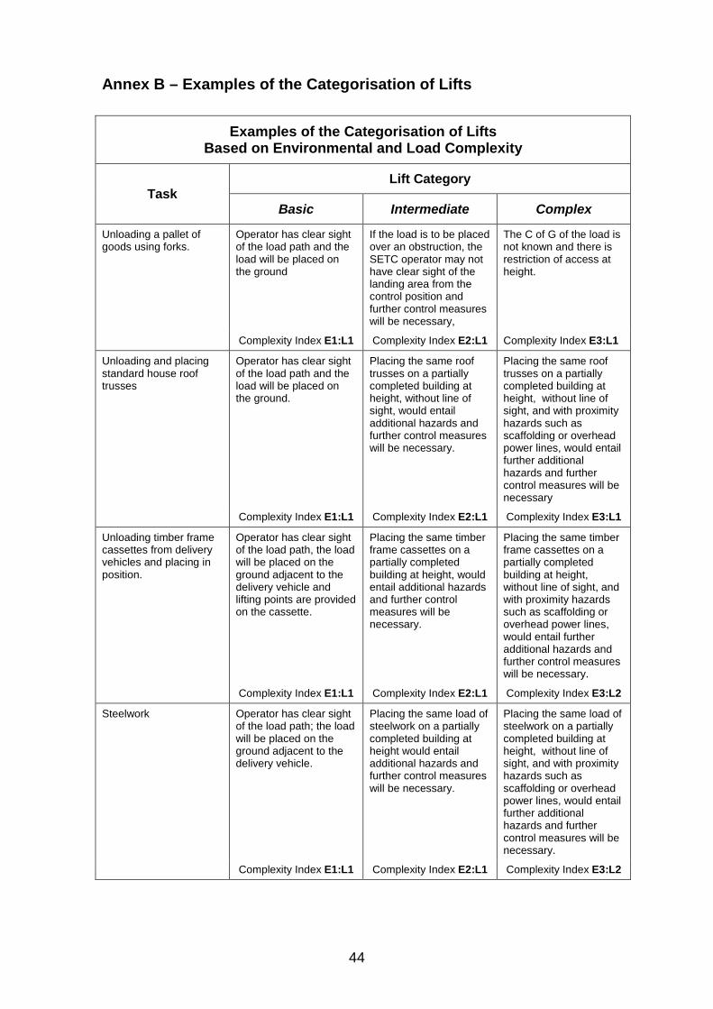
44
Annex B – Examples of the Categorisation of Lifts
Examples of the Categorisation of Lifts Based on Environmental and Load Complexity
Task Lift Category
Basic Intermediate Complex
Unloading a pallet of goods using forks.
Operator has clear sight of the load path and the load will be placed on the ground
If the load is to be placed over an obstruction, the SETC operator may not have clear sight of the landing area from the control position and further control measures will be necessary,
The C of G of the load is not known and there is restriction of access at height.
Complexity Index E1:L1 Complexity Index E2:L1 Complexity Index E3:L1
Unloading and placing standard house roof trusses
Operator has clear sight of the load path and the load will be placed on the ground.
Placing the same roof trusses on a partially completed building at height, without line of sight, would entail additional hazards and further control measures will be necessary.
Placing the same roof trusses on a partially completed building at height, without line of sight, and with proximity hazards such as scaffolding or overhead power lines, would entail further additional hazards and further control measures will be necessary
Complexity Index E1:L1 Complexity Index E2:L1 Complexity Index E3:L1
Unloading timber frame cassettes from delivery vehicles and placing in position.
Operator has clear sight of the load path, the load will be placed on the ground adjacent to the delivery vehicle and lifting points are provided on the cassette.
Placing the same timber frame cassettes on a partially completed building at height, would entail additional hazards and further control measures will be necessary.
Placing the same timber frame cassettes on a partially completed building at height, without line of sight, and with proximity hazards such as scaffolding or overhead power lines, would entail further additional hazards and further control measures will be necessary.
Complexity Index E1:L1 Complexity Index E2:L1 Complexity Index E3:L2
Steelwork
Operator has clear sight of the load path; the load will be placed on the ground adjacent to the delivery vehicle.
Placing the same load of steelwork on a partially completed building at height would entail additional hazards and further control measures will be necessary.
Placing the same load of steelwork on a partially completed building at height, without line of sight, and with proximity hazards such as scaffolding or overhead power lines, would entail further additional hazards and further control measures will be necessary.
Complexity Index E1:L1 Complexity Index E2:L1 Complexity Index E3:L2
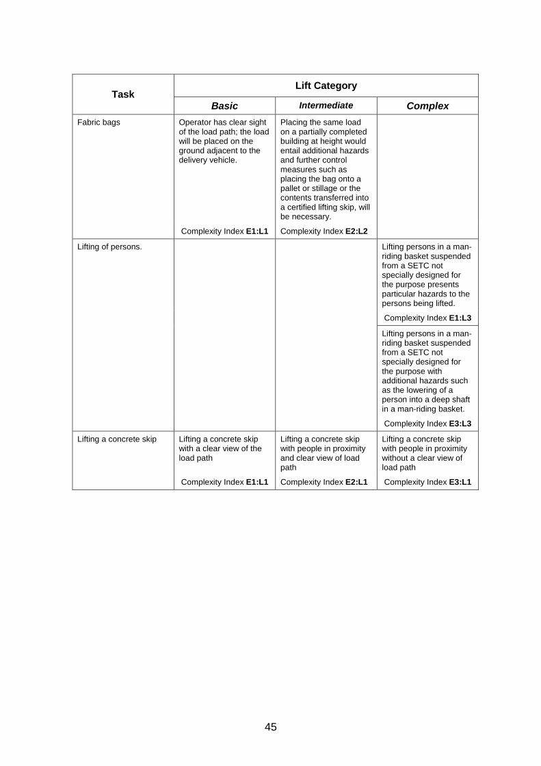
45
Task Lift Category
Basic Intermediate Complex
Fabric bags
Operator has clear sight of the load path; the load will be placed on the ground adjacent to the delivery vehicle.
Placing the same load on a partially completed building at height would entail additional hazards and further control measures such as placing the bag onto a pallet or stillage or the contents transferred into a certified lifting skip, will be necessary.
Complexity Index E1:L1 Complexity Index E2:L2
Lifting of persons. Lifting persons in a man-riding basket suspended from a SETC not specially designed for the purpose presents particular hazards to the persons being lifted.
Complexity Index E1:L3
Lifting persons in a man-riding basket suspended from a SETC not specially designed for the purpose with additional hazards such as the lowering of a person into a deep shaft in a man-riding basket.
Complexity Index E3:L3
Lifting a concrete skip Lifting a concrete skip with a clear view of the load path
Lifting a concrete skip with people in proximity and clear view of load path
Lifting a concrete skip with people in proximity without a clear view of load path
Complexity Index E1:L1 Complexity Index E2:L1 Complexity Index E3:L1
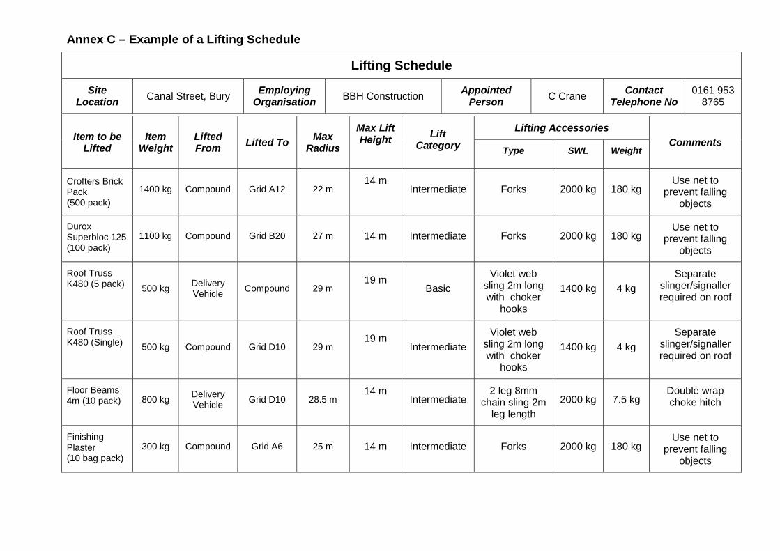
Annex C – Example of a Lifting Schedule
Lifting Schedule
Site Location Canal Street, Bury Employing
Organisation BBH Construction Appointed Person C Crane Contact
Telephone No 0161 953
8765
Item to be
Lifted Item
Weight Lifted From Lifted To Max
Radius
Max Lift Height
Lift Category
Lifting Accessories Comments
Type SWL Weight
Crofters Brick Pack (500 pack)
1400 kg Compound Grid A12 22 m 14 m
Intermediate Forks 2000 kg 180 kg
Use net to prevent falling
objects
Durox Superbloc 125 (100 pack)
1100 kg Compound Grid B20 27 m 14 m Intermediate Forks 2000 kg 180 kg Use net to
prevent falling objects
Roof Truss K480 (5 pack) 500 kg Delivery
Vehicle Compound 29 m 19 m
Basic
Violet web sling 2m long with choker
hooks
1400 kg 4 kg Separate
slinger/signaller required on roof
Roof Truss K480 (Single) 500 kg Compound Grid D10 29 m
19 m
Intermediate
Violet web sling 2m long with choker
hooks
1400 kg 4 kg Separate
slinger/signaller required on roof
Floor Beams 4m (10 pack) 800 kg Delivery
Vehicle Grid D10 28.5 m 14 m
Intermediate
2 leg 8mm chain sling 2m
leg length 2000 kg 7.5 kg
Double wrap choke hitch
Finishing Plaster (10 bag pack)
300 kg Compound Grid A6 25 m 14 m Intermediate Forks 2000 kg 180 kg Use net to
prevent falling objects
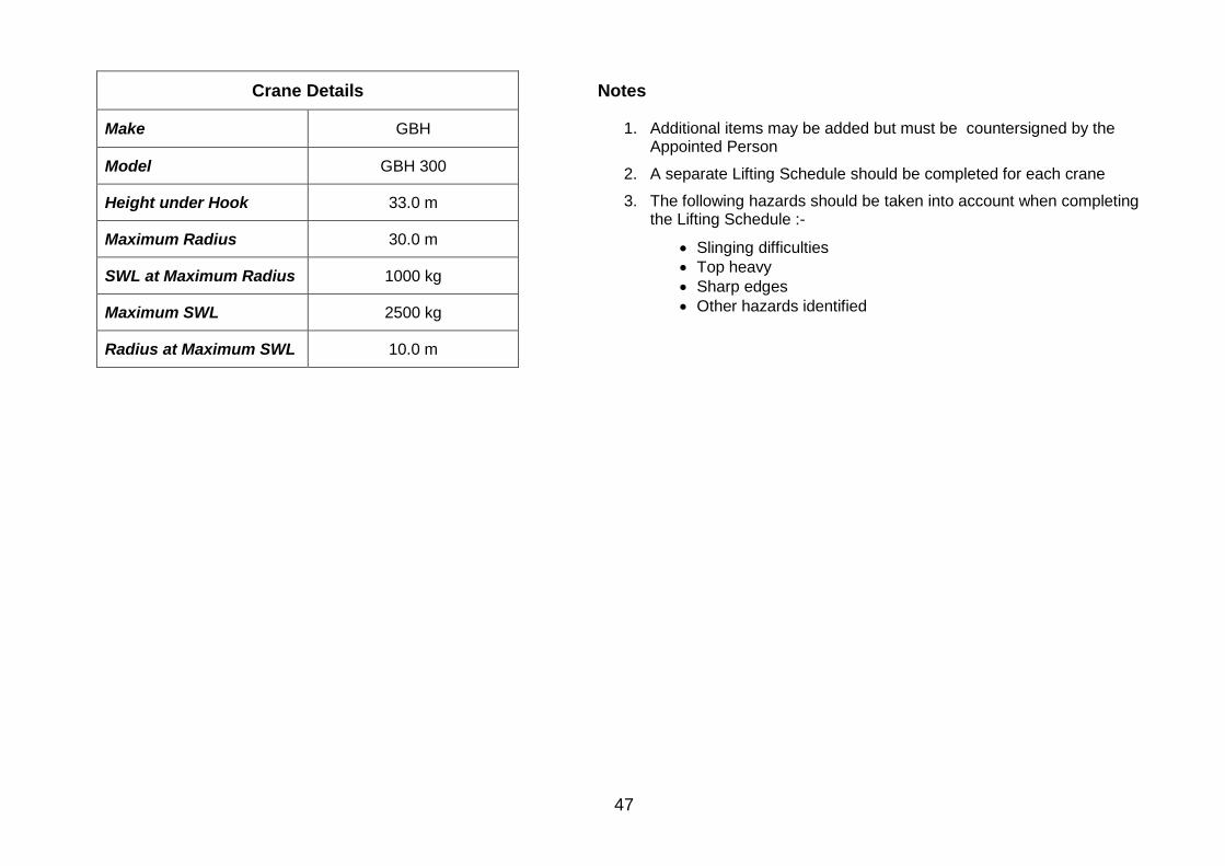
47
Crane Details Notes
Make GBH 1. Additional items may be added but must be countersigned by the Appointed Person
2. A separate Lifting Schedule should be completed for each crane
3. The following hazards should be taken into account when completing the Lifting Schedule :-
• Slinging difficulties • Top heavy • Sharp edges • Other hazards identified
Model GBH 300
Height under Hook 33.0 m
Maximum Radius 30.0 m
SWL at Maximum Radius 1000 kg
Maximum SWL 2500 kg
Radius at Maximum SWL 10.0 m
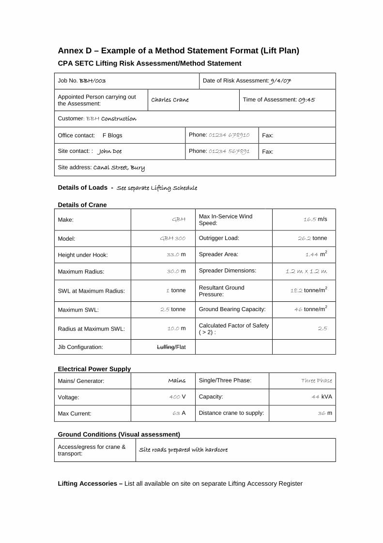
Annex D – Example of a Method Statement Format (Lift Plan) CPA SETC Lifting Risk Assessment/Method Statement
Job No. BBH/003 Date of Risk Assessment: 9/4/07
Appointed Person carrying out the Assessment:
Charles Crane Time of Assessment: 09:45
Customer: BBH Construction
Office contact: F Blogs Phone: 01234 678910 Fax:
Site contact: : John Doe Phone: 01234 567891 Fax:
Site address: Canal Street, Bury
Details of Loads - See separate Lifting Schedule Details of Crane
Make: GBH Max In-Service Wind Speed:
16.5 m/s
Model: GBH 300 Outrigger Load: 26.2 tonne
Height under Hook: 33.0 m Spreader Area: 1.44 m2
Maximum Radius: 30.0 m Spreader Dimensions: 1.2 m x 1.2 m
SWL at Maximum Radius: 1 tonne Resultant Ground Pressure:
18.2 tonne/m2
Maximum SWL: 2.5 tonne Ground Bearing Capacity: 46 tonne/m2
Radius at Maximum SWL: 10.0 m Calculated Factor of Safety ( > 2) :
2.5
Jib Configuration: Luffing/Flat
Electrical Power Supply
Mains/ Generator: Mains Single/Three Phase: Three Phase
Voltage: 400 V Capacity: 44 kVA
Max Current: 63 A Distance crane to supply: 36 m
Ground Conditions (Visual assessment)
Access/egress for crane & transport:
Site roads prepared with hardcore
Lifting Accessories – List all available on site on separate Lifting Accessory Register
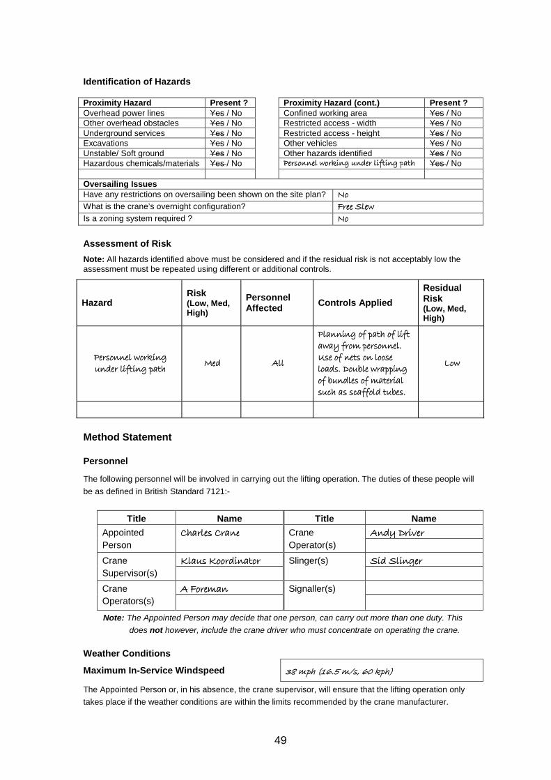
49
Identification of Hazards Proximity Hazard Present ? Proximity Hazard (cont.) Present ? Overhead power lines Yes / No Confined working area Yes / No Other overhead obstacles Yes / No Restricted access - width Yes / No Underground services Yes / No Restricted access - height Yes / No Excavations Yes / No Other vehicles Yes / No Unstable/ Soft ground Yes / No Other hazards identified Yes / No Hazardous chemicals/materials Yes / No Personnel working under lifting path Yes / No Oversailing Issues Have any restrictions on oversailing been shown on the site plan? No What is the crane’s overnight configuration? Free Slew Is a zoning system required ? No
Assessment of Risk Note: All hazards identified above must be considered and if the residual risk is not acceptably low the assessment must be repeated using different or additional controls.
Hazard Risk (Low, Med, High)
Personnel Affected Controls Applied
Residual Risk (Low, Med, High)
Personnel working under lifting path Med All
Planning of path of lift away from personnel. Use of nets on loose loads. Double wrapping of bundles of material such as scaffold tubes.
Low
Method Statement Personnel
The following personnel will be involved in carrying out the lifting operation. The duties of these people will be as defined in British Standard 7121:-
Title Name Title Name Appointed Person
Charles Crane Crane Operator(s)
Andy Driver
Crane Supervisor(s)
Klaus Koordinator Slinger(s) Sid Slinger
Crane Operators(s)
A Foreman Signaller(s)
Note: The Appointed Person may decide that one person, can carry out more than one duty. This does not however, include the crane driver who must concentrate on operating the crane.
Weather Conditions
Maximum In-Service Windspeed 38 mph (16.5 m/s, 60 kph)
The Appointed Person or, in his absence, the crane supervisor, will ensure that the lifting operation only takes place if the weather conditions are within the limits recommended by the crane manufacturer.
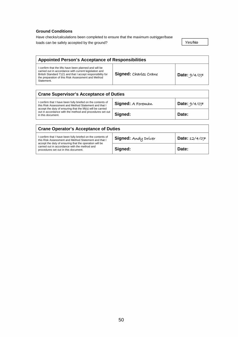
50
Ground Conditions Have checks/calculations been completed to ensure that the maximum outrigger/base loads can be safely accepted by the ground? Appointed Person’s Acceptance of Responsibilities I confirm that the lifts have been planned and will be carried out in accordance with current legislation and British Standard 7121 and that I accept responsibility for the preparation of this Risk Assessment and Method Statement.
Signed: Charles Crane Date: 9/4/07
Crane Supervisor’s Acceptance of Duties I confirm that I have been fully briefed on the contents of this Risk Assessment and Method Statement and that I accept the duty of ensuring that the lift(s) will be carried out in accordance with the method and procedures set out in this document.
Signed: A Foreman Date: 9/4/07
Signed: Date:
Crane Operator’s Acceptance of Duties I confirm that I have been fully briefed on the contents of this Risk Assessment and Method Statement and that I accept the duty of ensuring that the operation will be carried out in accordance with the method and procedures set out in this document.
Signed: Andy Driver Date: 12/4/07
Signed: Date:
Yes/No
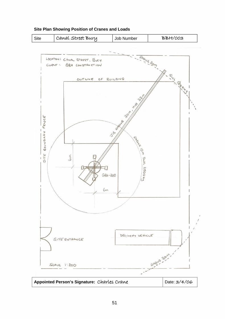
51
Site Plan Showing Position of Cranes and Loads
Appointed Person’s Signature: Charles Crane Date: 3/4/06
Site Canal Street Bury Job Number BBH/003
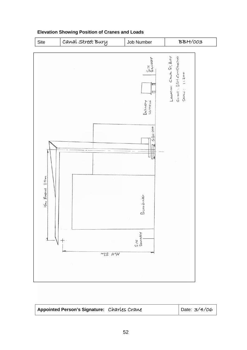
52
Elevation Showing Position of Cranes and Loads
Appointed Person’s Signature: Charles Crane Date: 3/4/06
Site Canal Street Bury Job Number BBH/003
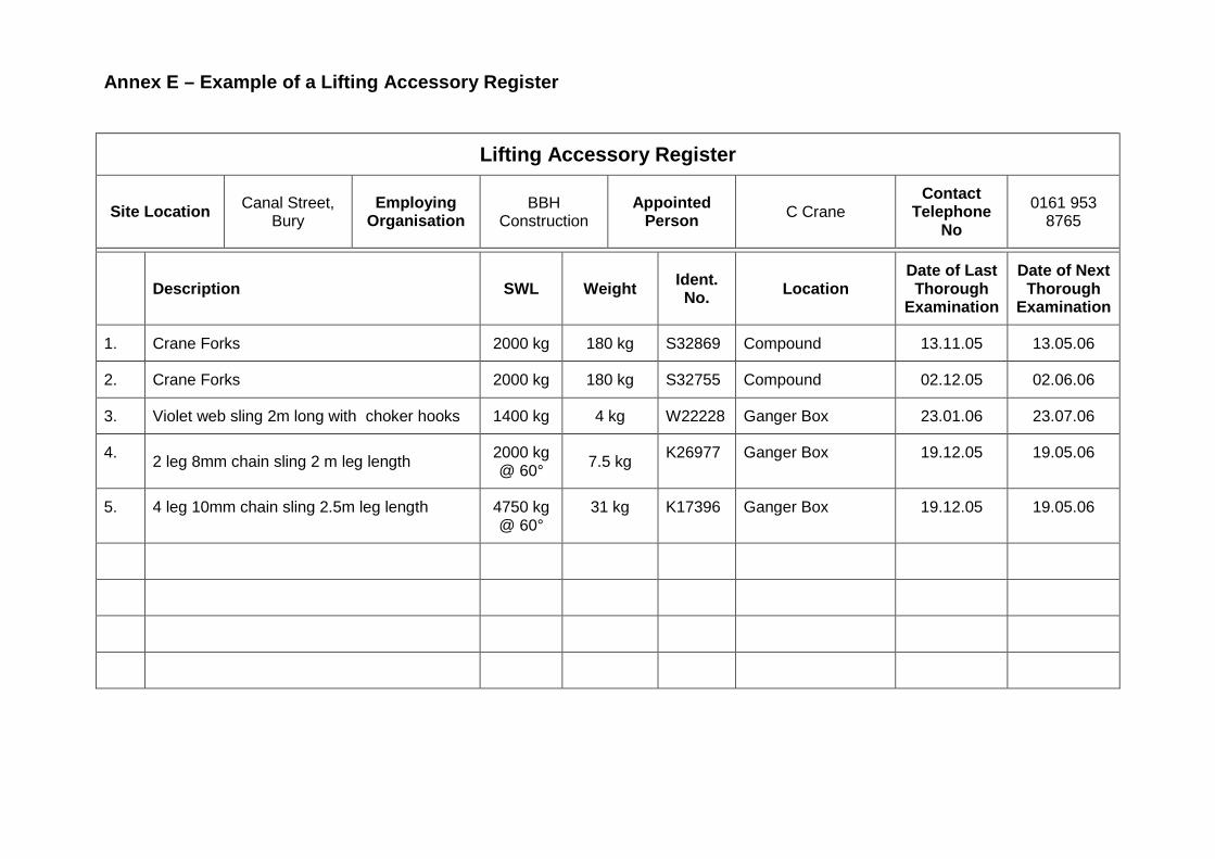
Annex E – Example of a Lifting Accessory Register
Lifting Accessory Register
Site Location Canal Street, Bury
Employing Organisation
BBH Construction
Appointed Person C Crane
Contact Telephone
No
0161 953 8765
Description SWL Weight Ident.
No. Location Date of Last Thorough
Examination
Date of Next Thorough
Examination
1. Crane Forks 2000 kg 180 kg S32869 Compound 13.11.05 13.05.06
2. Crane Forks 2000 kg 180 kg S32755 Compound 02.12.05 02.06.06
3. Violet web sling 2m long with choker hooks 1400 kg 4 kg W22228 Ganger Box 23.01.06 23.07.06
4. 2 leg 8mm chain sling 2 m leg length 2000 kg @ 60° 7.5 kg K26977 Ganger Box 19.12.05 19.05.06
5. 4 leg 10mm chain sling 2.5m leg length 4750 kg @ 60°
31 kg K17396 Ganger Box 19.12.05 19.05.06
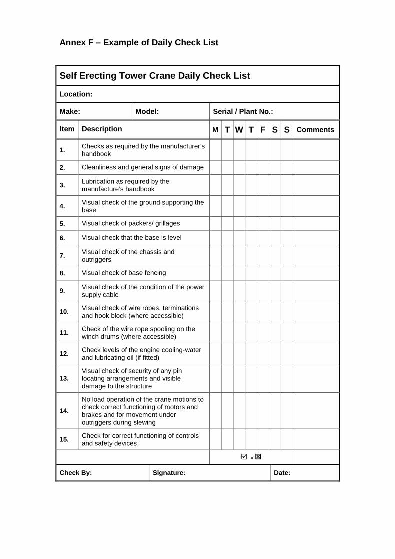
Annex F – Example of Daily Check List
Self Erecting Tower Crane Daily Check List
Location:
Make: Model: Serial / Plant No.:
Item Description M T W T F S S Comments
1. Checks as required by the manufacturer’s handbook
2. Cleanliness and general signs of damage
3. Lubrication as required by the manufacture’s handbook
4. Visual check of the ground supporting the base
5. Visual check of packers/ grillages
6. Visual check that the base is level
7. Visual check of the chassis and outriggers
8. Visual check of base fencing
9. Visual check of the condition of the power supply cable
10. Visual check of wire ropes, terminations and hook block (where accessible)
11. Check of the wire rope spooling on the winch drums (where accessible)
12. Check levels of the engine cooling-water and lubricating oil (if fitted)
13. Visual check of security of any pin locating arrangements and visible damage to the structure
14. No load operation of the crane motions to check correct functioning of motors and brakes and for movement under outriggers during slewing
15. Check for correct functioning of controls and safety devices
or
Check By: Signature: Date:
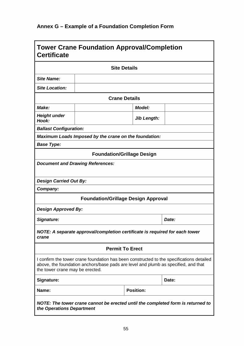
55
Annex G – Example of a Foundation Completion Form
Tower Crane Foundation Approval/Completion Certificate
Site Details
Site Name:
Site Location:
Crane Details
Make: Model: Height under Hook: Jib Length:
Ballast Configuration: Maximum Loads Imposed by the crane on the foundation: Base Type:
Foundation/Grillage Design
Document and Drawing References:
Design Carried Out By: Company:
Foundation/Grillage Design Approval
Design Approved By:
Signature: Date:
NOTE: A separate approval/completion certificate is required for each tower crane
Permit To Erect
I confirm the tower crane foundation has been constructed to the specifications detailed above, the foundation anchors/base pads are level and plumb as specified, and that the tower crane may be erected.
Signature: Date:
Name: Position:
NOTE: The tower crane cannot be erected until the completed form is returned to the Operations Department
56
Annex H – Work at Height
H1.1.0 Introduction
Working at height is an inevitable part of the maintenance and thorough examination of tower cranes and should be carried out by trained personnel, following careful planning which includes adequate assessment of the risks involved. This planning should include provision for the rescue of persons.
Health and Safety legislation requires that safe systems of work are in place for all work activities and the particular references for the requirement to provide safe access, egress and a means of safe rescue are:-
• Health and Safety at Work etc. Act 1974. - Sections 2 & 3
• Work at Height Regulations 2005
• Provision and Use of Work Equipment Regulations (PUWER) 1998 – Regulation 17
• Lifting Operations and Lifting Equipment Regulations (LOLER) 1998 – Regulation 3
• Management of Health and Safety at Work Regulations 1999 – Regulation 3
• Construction Design and Management Regulations 2007
H1.2.0 Responsibility for Planning of Work at Height and Provision of Rescue Resources
It is clear that the primary duty for ensuring that work at height on a tower crane is effectively planned and that there are adequate resources for carrying out rescue of persons from height, rests with the organization in control of the premises on which any tower crane is sited. In the case of a construction site this will be the Principal Contractor as defined by the Construction (Design and Management) Regulations 2007.
In practice it is likely that:-
• Arrangements for work at height during maintenance and thorough examination will be made by the tower crane supplier;
• Arrangements for rescue during maintenance and thorough examination will be made by the tower crane supplier.
H1.3.0 Guidance for Work at Height The Work at Height Regulations 2005 set out a hierarchy of fall protection measures to be taken when planning work at height.
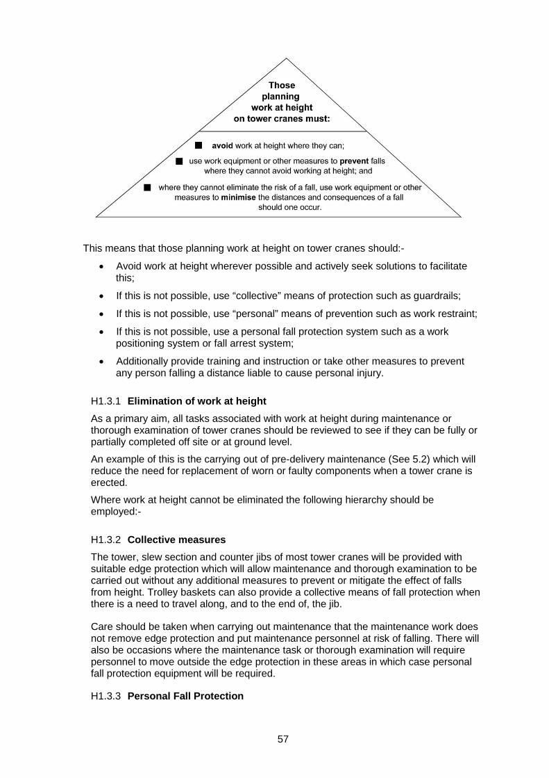
57
This means that those planning work at height on tower cranes should:-
• Avoid work at height wherever possible and actively seek solutions to facilitate this;
• If this is not possible, use “collective” means of protection such as guardrails;
• If this is not possible, use “personal” means of prevention such as work restraint;
• If this is not possible, use a personal fall protection system such as a work positioning system or fall arrest system;
• Additionally provide training and instruction or take other measures to prevent any person falling a distance liable to cause personal injury.
H1.3.1 Elimination of work at height As a primary aim, all tasks associated with work at height during maintenance or thorough examination of tower cranes should be reviewed to see if they can be fully or partially completed off site or at ground level.
An example of this is the carrying out of pre-delivery maintenance (See 5.2) which will reduce the need for replacement of worn or faulty components when a tower crane is erected.
Where work at height cannot be eliminated the following hierarchy should be employed:-
H1.3.2 Collective measures The tower, slew section and counter jibs of most tower cranes will be provided with suitable edge protection which will allow maintenance and thorough examination to be carried out without any additional measures to prevent or mitigate the effect of falls from height. Trolley baskets can also provide a collective means of fall protection when there is a need to travel along, and to the end of, the jib.
Care should be taken when carrying out maintenance that the maintenance work does not remove edge protection and put maintenance personnel at risk of falling. There will also be occasions where the maintenance task or thorough examination will require personnel to move outside the edge protection in these areas in which case personal fall protection equipment will be required.
H1.3.3 Personal Fall Protection
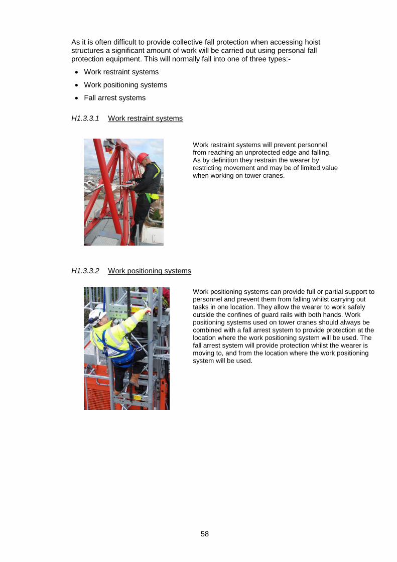
58
As it is often difficult to provide collective fall protection when accessing hoist structures a significant amount of work will be carried out using personal fall protection equipment. This will normally fall into one of three types:-
• Work restraint systems
• Work positioning systems
• Fall arrest systems
H1.3.3.1 Work restraint systems
H1.3.3.2 Work positioning systems
Work restraint systems will prevent personnel from reaching an unprotected edge and falling. As by definition they restrain the wearer by restricting movement and may be of limited value when working on tower cranes.
Work positioning systems can provide full or partial support to personnel and prevent them from falling whilst carrying out tasks in one location. They allow the wearer to work safely outside the confines of guard rails with both hands. Work positioning systems used on tower cranes should always be combined with a fall arrest system to provide protection at the location where the work positioning system will be used. The fall arrest system will provide protection whilst the wearer is moving to, and from the location where the work positioning system will be used.
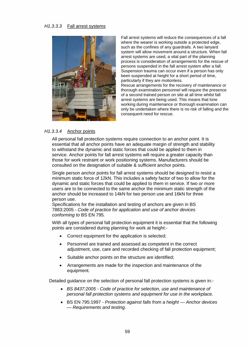
59
H1.3.3.3 Fall arrest systems
H1.3.3.4 Anchor points
All personal fall protection systems require connection to an anchor point. It is essential that all anchor points have an adequate margin of strength and stability to withstand the dynamic and static forces that could be applied to them in service. Anchor points for fall arrest systems will require a greater capacity than those for work restraint or work positioning systems. Manufacturers should be consulted on the designation of suitable & sufficient anchor points.
Single person anchor points for fall arrest systems should be designed to resist a minimum static force of 12kN. This includes a safety factor of two to allow for the dynamic and static forces that could be applied to them in service. If two or more users are to be connected to the same anchor the minimum static strength of the anchor should be increased to 14kN for two person use and 16kN for three person use. Specifications for the installation and testing of anchors are given in BS 7883:2005 - Code of practice for application and use of anchor devices conforming to BS EN 795.
With all types of personal fall protection equipment it is essential that the following points are considered during planning for work at height:-
• Correct equipment for the application is selected;
• Personnel are trained and assessed as competent in the correct adjustment, use, care and recorded checking of fall protection equipment;
• Suitable anchor points on the structure are identified;
• Arrangements are made for the inspection and maintenance of the equipment.
Detailed guidance on the selection of personal fall protection systems is given in:-
• BS 8437:2005 - Code of practice for selection, use and maintenance of personal fall protection systems and equipment for use in the workplace.
• BS EN 795:1997 - Protection against falls from a height — Anchor devices — Requirements and testing.
Fall arrest systems will reduce the consequences of a fall where the wearer is working outside a protected edge, such as the confines of any guardrails. A two lanyard system will allow movement around a structure. When fall arrest systems are used, a vital part of the planning process is consideration of arrangements for the rescue of persons suspended in the fall arrest system after a fall. Suspension trauma can occur even if a person has only been suspended at height for a short period of time, particularly if they are motionless. Rescue arrangements for the recovery of maintenance or thorough examination personnel will require the presence of a second trained person on site at all time whilst fall arrest systems are being used. This means that lone working during maintenance or thorough examination can only be undertaken where there is no risk of falling and the consequent need for rescue.
60
H1.4.0 Rescue from suspension in a fall arrest harness A suitable rescue system such as the Spanset “Gotcha” system may be used in this situation. This system is contained in a bag, taken up the tower crane by the maintenance team and kept there whenever fall arrest systems are in use. In the event of a person falling and being suspended in the fall arrest system his colleagues will attach a block and tackle to the crane structure and clip one end of the fibre rescue rope to the casualty’s harness ring using the telescoping pole provided. The casualty can then be raised back up to the crane structure or lowered to the ground (after the casualty’s harness lanyard has been severed).
The Gotcha system is always operated by members of the maintenance team who have been trained by the system manufacturer or by in-house trainers trained and authorised by the manufacturer. In planning for rescue from height, reliance should not be placed on the use of the Emergency Services without first consulting those services
Suspension in a harness for a period of time (often as little a ten minutes) without moving may give rise to “suspension trauma” which leads to pooling of blood in the veins of the lower limbs. This can cause disturbance to the circulatory system leading to damage of the vital organs. When rescuing a suspended person care must be taken to avoid moving them into a horizontal position as this can cause a massive flow of venous blood to the heart, which cannot cope, and this can cause potentially fatal cardiac abnormalities. Additional information on suspension trauma is given in Annex D of BS 8437:2005 - Code of practice for selection, use and maintenance of personal fall protection systems and equipment for use in the workplace.
Additional information on access and work at height on tower cranes is given in the following TINs in the CPA Technical Information Note series:
• TIN 001 Access to Tower Cranes After Commissioning • TIN 003 Tower Crane Access Procedures • TIN 006 Tower Crane Access Ladders • TIN 008 Tower Crane Edge Protection • TIN 009 Security of Access to the Crane Base • TIN 013 Rescue of Personnel From Height on Tower Cranes • TIN 015 Risk Assessment – General Access to Tower Cranes (including for
maintenance) • TIN 016 Fall Protection Equipment For Tower Crane Operators

61
Annex I – Guidance on the Lifting of Persons I.1.0 General Raising and lowering of personnel by a SETC that is not specifically designed for this purpose should only be carried out in exceptional circumstances, when it is not practicable to do so by any other less hazardous means (e.g scaffolding, mobile elevating work platform, mast climbing work platform).
Careful planning of the event should be carried out prior to each raising and lowering operation. NOTE 1 Attention is drawn to LOLER [1] regarding the planning of lifting operations.
NOTE 2 Further details on raising and lowering personnel are given in ISO 12480-1 & BS EN 14502-1.
NOTE 3 The crane manufacturer’s instructions must be consulted before the crane is used for lifting of persons
I.2.0 Carrier The type of carrier selected when raising/lowering personnel should depend on a risk assessment and varies according to the application, for example construction, forestry, rescue. New carriers should comply with BS EN 14502-1
I.3.0 Compatibility of carrier and crane I.3.1 Capacity The crane selected to lift the carrier should have a rated capacity on the fixed load lifting attachment of at least twice the minimum rated capacity of the crane configuration in use.
I.3.2 Motion control system The crane should be equipped with a motion control system that brings motion to rest automatically when the controls are released.
The crane should be equipped with power lowering. Cranes with free-fall capability should not be used to lower and raise persons unless the free-fall facility is locked out.
Load bearing hydraulic cylinders should be fitted with a device to stop movement in case of hose rupture or pipe fracture.
The crane control system should be able to provide a smooth transition of the carrier. The working speed of the carrier should be limited to a maximum of 0.5 m/s on all motions.
Means should be provided so that if the power supply or control system fails, the carrier can be positioned to enable access/egress without risk.
I.3.3 Ropes Ropes used for hoisting and lowering the carrier should have a minimum diameter of 8 mm.
I.3.4 Hook The crane hook should be provided with a safety catch.
62
I.3.5 Lifting Accessories
Lifting accessories used to connect the carrier to the crane hook should :-
• require a tool to make or break any connection to the carrier and masterlink;
• only to have been used previously for the lifting of persons;
• have a masterlink sized to fit the crane hook.
I.4.0 Thorough examination and pre-use checks Additional recommendations for the thorough examination and pre-use checks of cranes and carriers for lifting persons are given in BS 7121-2:2003, Clause 11.
I.5.0 Other devices/facilities I.5.1 Anemometer The crane should be fitted with an anemometer or other device to monitor in-service wind speeds.
I.5.2 Storage Storage accommodation for equipment, including any emergency egress equipment, should be provided in the carrier.
I.5.3 Rated capacity limiter/rated capacity indicator The rated capacity limiter/rated capacity indicator on the crane should be maintained in good working order.
Limit switches should be provided to prevent over-hoisting, over-lowering or over-derricking.
The operator should check limit switches for correct operation each day before personnel carrying operations are carried out. Limit switches are not necessarily fail safe and therefore care should be taken if motion limits are approached.
A fail safe procedure should be provided to ensure that sufficient hoist rope remains on the winch drum at all times to prevent the end of the rope running off the drum while lowering the carrier.
To ensure that sufficient rope remains on the drum at all times, the empty carrier should be lowered as a trial to the bottom of the shaft, cofferdam or caisson as follows:
• The first time it is lowered;
• After each time the shaft, cofferdam or caisson depth increases;
• If the crane hoist rope is replaced.
Care should be taken when the crane is moved to different locations to ensure that sufficient rope is fitted for each operation.
Operation of limit switches, check valves and similar devices could prevent some motions of the crane with the carrier still suspended. Precautions should be taken to ensure that persons in the carrier are not left suspended for an excessive period, and/or a procedure for raising or lowering the carrier to a safe position should be provided.
63
I.6.0 Operation I.6.1 Organizational requirements Lifting, lowering and supporting the carrier should be carried out by the operator in controlled conditions from the normal control station, directed by an appointed signaller. The operator must not operate the SETC from the carrier.
It is essential that the crane operator is present at the normal crane control station when the carrier is occupied. Visible and audible communication should be possible between the persons in the carrier and the crane operator at all times during the lifting operation. If a wireless control station is used it is essential that it is being worn by the operator whenever the carrier is occupied. The controls must be switched on and the carrier in full view of the operator at all times.
During the operation:
• An adequately trained and briefed person should be present to perform any emergency recovery procedure;
• The crane operator and signaller should not perform any other work at the same time. The crane operator and signaller should only be responsible for operating one crane or directing one carrier;
• Machines should not operate simultaneously in the same place if there could be a risk of collision;
• All movements should proceed gently and not exceed 0.5 m/s.
Carriers should not be used in the following conditions:
• Winds exceeding 7 m/s (25 km/h). Windspeed measurements should be taken using a calibrated handheld anemometer at a similar level to that to which the carrier will be lifted;
• Electrical storms;
• Snow or ice;
• Fog;
• Sleet;
• Other weather conditions that could affect the safety of personnel.
Unintentional rotation of the carrier should be prevented, for example by using guide ropes or anchoring. The means of preventing unintentional rotation should not inhibit any emergency procedures and otherwise interfere with the safe operation of the carrier.
Lifts should not be made on any other hoist lines of the crane while any person occupies a carrier attached to the crane.
The crane, load lifting attachments and carrier should be inspected prior to use every working day. NOTE For further information on inspections see BS 7121-2. An example of a personnel carrier pre-use check form is given in BS 7121-2:2003, Annex E.
I.6.2 Precautions for persons in the carrier The payload of the carrier should not be exceeded.
The stability of the carrier should not be affected by the operation.
Additional care should be taken if the carrier is of a length that could lead to excessive tilting through movement of persons or tools within the carrier.
64
It is strongly recommended that all users of carriers wear suitable full body harnesses with work restraint systems attached to a suitable anchorage point in the carrier. The most suitable type of work restraint system is an adjustable lanyard, adjusted to be as short as possible to ensure that a person is restrained within the carrier. Further information on the use of personal fall protection equipment is given in BS 8437.
Consideration should be given to the rescue of persons from carriers if the carrier is unable to be lowered for any reason, such as machine malfunction or carrier entanglement. Any rescue procedure should be properly planned, taking into account the reasons why the carrier is stranded at height and any need for urgent action. In many circumstances the rescue plan simply involves lowering of the carrier by the supporting crane.
In the event that fall arrest equipment is selected, a rescue plan is required to avoid the consequences of suspension trauma when a person is suspended from a fall arrest harness.
Any tools/materials in the carrier should be secured to prevent displacement, tipping and/or falling out.
Personnel should remain entirely inside the carrier during raising, lowering and positioning to avoid pinch points. Personnel should only stand on or work from the floor of the carrier.
Carriers should be secured so that access and egress can be accomplished without danger. NOTE Crane suspended manriding cages should not generally be provided in lieu of fixed access/egress methods
I.7.0 Work from a carrier NOTE 1 Exposed electrical conductors in the vicinity of the lifting operation can present electrical hazards. Exposed high voltage conductors can cause electric shocks or burns even if not touched by personnel. If there are electrical conductors adjacent to the work area, seek advice from the owner of the conductor. Overhead lines usually belong to the local electricity supplier or the National Grid company. These suppliers can provide advice on safe working distances from electrical conductors.
If electric arc welding is carried out from a carrier, precautions should be taken to prevent stray welding return currents from flowing through the load lifting attachments, crane hoist rope, or other part of the crane. Electric arc welding should be carried out in accordance with HS G 118 [23]. The return welding current lead should be secured to the welded part, as close as practicable to the point of the weld. NOTE 2 Complete insulation of the crane hoist rope or use of clean dry webbing lifting attachments can also prevent stray currents.
Electric powered hand tools, if used, should be battery powered.
Power cables provided to the carrier should not interfere with safe operation of the carrier.
Power cables should not be used as steady lines.
65
Annex J – Radio Communications for Lifting Operations –TIN 017 Introduction Tower cranes often work on congested construction sites where the signaller is out of sight of the tower crane operator and the standard hand signals specified in BS 7121 cannot be used. As an alternative, hand held VHF/UHF radios are often used. This however, can lead to a number of problems which may interfere with the clear communication vital for safe lifting operations:- • Loss of signal and thus communication, leading to loss of control of the lifting
operation; • Interference from radios on adjacent sites, which can lead to loss of communication
or directions being given to the wrong crane operator; • Misunderstanding between the crane operator and the signaller, leading to
problems such as a load being lifted before the slinger has his hands clear, loads colliding with the building structure and the load being lowered before people are clear of the landing area.
Radio Specification The first two issues should be addressed by specification of the correct radio equipment for the application taking into account:- • Signal strength – if it is too low there is a risk of signal loss - too high and it will
cause interference with adjacent sites. When working blind the structure may well cause signal loss and a booster aerial could be required. Signal strength should be checked at the beginning of each shift before lifting operations are started;
• Frequency – choosing a different frequency from other radios on the site or in the area will avoid interference from or to other radios;
• Durability – radio hand sets should be sufficiently durable to withstand use on site; • Charging – adequate charging arrangements to ensure that batteries are charged
at the end of a shift and that spare charged batteries are available at all times; • Battery capacity – sufficient capacity to last for a full shift.
Calls Signs and Standard Commands The third issue, misunderstandings between the crane operator and signaller, should be addressed as follows:- • Both parties must have a sufficient command of a common language (normally
English) to ensure that clear, unambiguous communication can take place; • A clear, unique call sign should be allocated to each signaller and crane operator; • Each message should preceded by the call sign (e.g. TC1….); • The crane operator should not respond to any command (other than Stop) that is
not preceded by the call sign; • Voice commands must only be given by one person, normally the signaller, at
any one time; • Voice commands should be given using the signals in the following table.
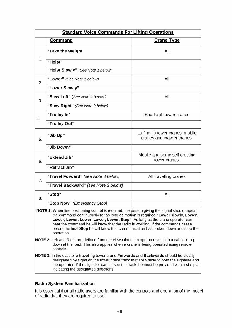
66
Standard Voice Commands For Lifting Operations Command Crane Type
1.
“Take the Weight” All
“Hoist” “Hoist Slowly” (See Note 1 below)
2. “Lower” (See Note 1 below) All
“Lower Slowly”
3. “Slew Left” (See Note 2 below ) All
“Slew Right” (See Note 2 below)
4. “Trolley In” Saddle jib tower cranes
“Trolley Out”
5. “Jib Up” Luffing jib tower cranes, mobile
cranes and crawler cranes
“Jib Down”
6. “Extend Jib” Mobile and some self erecting
tower cranes
“Retract Jib”
7. “Travel Forward” (see Note 3 below) All travelling cranes
“Travel Backward” (see Note 3 below)
8. “Stop” All
“Stop Now” (Emergency Stop) NOTE 1: When fine positioning control is required, the person giving the signal should repeat
the command continuously for as long as motion is required “Lower slowly, Lower, Lower, Lower, Lower, Lower, Lower, Stop”. As long as the crane operator can hear the command he will know that the radio is working. If the commands cease before the final Stop he will know that communication has broken down and stop the operation.
NOTE 2: Left and Right are defined from the viewpoint of an operator sitting in a cab looking down at the load. This also applies when a crane is being operated using remote controls.
NOTE 3: In the case of a travelling tower crane Forwards and Backwards should be clearly designated by signs on the tower crane track that are visible to both the signaller and the operator. If the signaller cannot see the track, he must be provided with a site plan indicating the designated directions.
Radio System Familiarization It is essential that all radio users are familiar with the controls and operation of the model of radio that they are required to use.
67
Anti-collision Radio Systems On sites where multiple tower cranes are installed and there is the possibility of jibs, counter jibs and hoist ropes clashing, an anti-collision radio system should be installed. This comprises of a separate radio in each tower crane cab operating on a unique frequency to allow open, unimpeded communication between all the tower crane operators. In the event of the jib or counter jib of one crane approaching the hoist rope of a higher crane the operator of the higher crane can immediately warn the operator of the lower crane.
Radio Licensing Requirements Radios used for two way communication on construction sites, and for industrial use, are referred to as Private Mobile Radio (PMR). Some low powered PMR radios use a European system called PMR446 and do not require a licence. This system is however limited to 8 UHF frequencies, each with 38 channels, which may lead to interference from other users. PMR446 radios are also limited to a maximum of 500 mW Effective Radiated Power, which gives a range of 0.5 to 1 mile in built up areas and 2 miles in open country.
More powerful radios work on VHF and UHF radio frequencies which are assigned to a user by OFCOM who also regulate the frequency bands. To obtain a licence on one of these frequencies an application needs to be made to OFCOM. The benefits of a licensed frequency are generally greater range, less interference from other users and more features available on the radio sets.
These frequencies are allocated to businesses only, on a case-by-case basis. Once the licence has been issued, radios can be purchased. The supplier will need to see a copy of the licence to program the radios to the correct frequency before shipping.
Additional guidance is given in:-
• Information Sheet RA 195. Business radio communications for tower cranes published by OFCOM at www.ofcom.org.uk/static/archive/ra/publication/ra-info.htm
• BS 7121-5:2006 Code of Practice for Safe Use of Cranes – Part 5: Tower Cranes
Annex K - Blind Lifting Blind lifting, where the tower crane operator cannot see the full path of the load from pick up area to set down area involves particular hazards. Consequently great care should be exercised in the planning and carrying out of such lifts.
Planning • The path of the load should be surveyed for hazards such as
obstructions, people working below, snagging points and radio blind spots.
• The hazards should be assessed and adequate measures put in place to control those hazards (e.g. sufficient signallers to keep the load in sight at all times and direct the tower crane operator).
• The personnel involved in the lift should be fully briefed on the lift plan and their role in the operation.
• The use of tag lines to control long loads should be assessed for potential snagging. (See TIN 022)
Lifting • Before starting to lift the load path should be checked to ensure that
additional hazards have not occurred such as changes to scaffolding or the permanent structure.
• Weather conditions should be checked to ensure that wind speeds are at or below an acceptable level for the size and weight of the load. Wind speed may well differ on opposite sides of a building or other structure.
• All radios used for signalling should be checked for battery charge and correct functioning at all signalling positions.
• All lifting motions should be carried out at a slow speed to ensure that the load does not swing and snag on the structure.
• The standard voice commands for lifting operations contained in Annex H (TIN017) should be used at all times.
• If the tower crane operator looses contact with the slinger or any of the signallers at any time during the lifting operation he must immediately stop the lift and contact the crane supervisor for instructions.
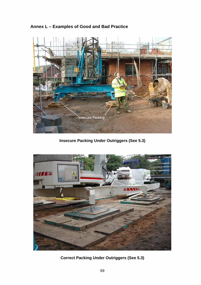
69
Annex L – Examples of Good and Bad Practice
Insecure Packing Under Outriggers (See 5.3)
Correct Packing Under Outriggers (See 5.3)
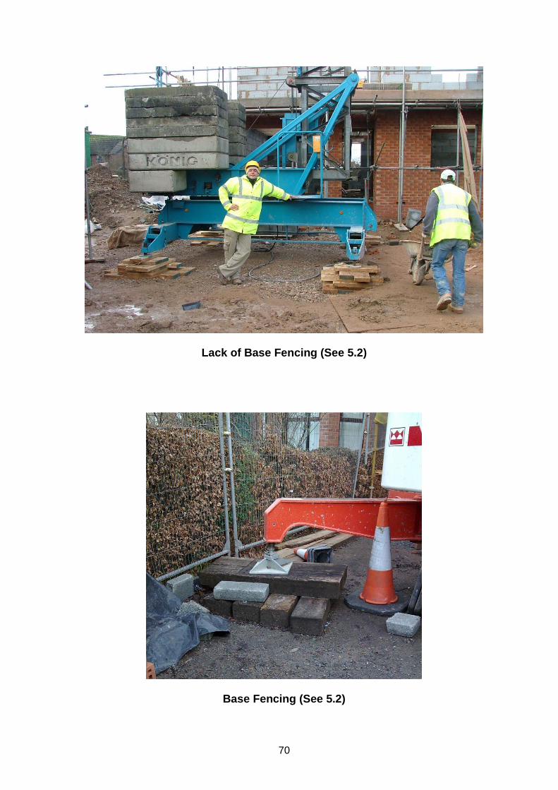
70
Lack of Base Fencing (See 5.2)
Base Fencing (See 5.2)
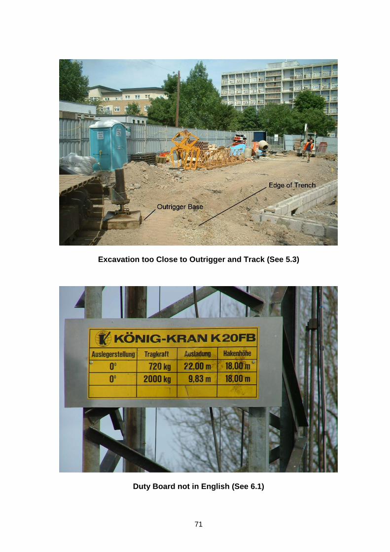
71
Excavation too Close to Outrigger and Track (See 5.3)
Duty Board not in English (See 6.1)

72
Installing Ballast using Full Harnesses with Inertia Reel Lanyards
Installing Ballast using Full Harnesses with Inertia Reel Lanyards
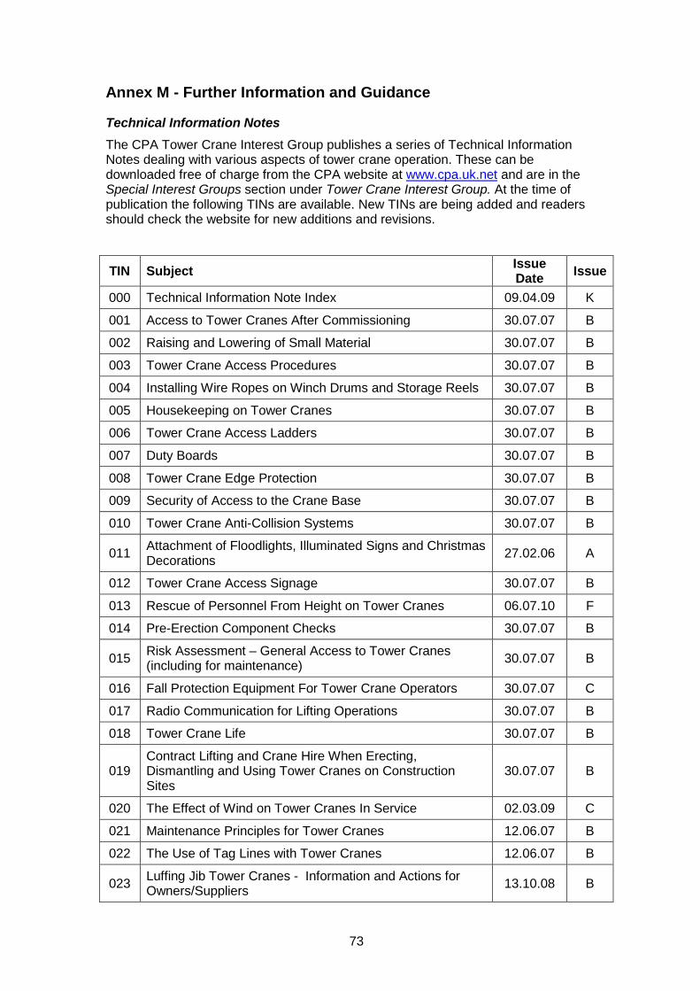
73
Annex M - Further Information and Guidance
Technical Information Notes The CPA Tower Crane Interest Group publishes a series of Technical Information Notes dealing with various aspects of tower crane operation. These can be downloaded free of charge from the CPA website at www.cpa.uk.net and are in the Special Interest Groups section under Tower Crane Interest Group. At the time of publication the following TINs are available. New TINs are being added and readers should check the website for new additions and revisions.
TIN Subject Issue Date Issue
000 Technical Information Note Index 09.04.09 K
001 Access to Tower Cranes After Commissioning 30.07.07 B
002 Raising and Lowering of Small Material 30.07.07 B
003 Tower Crane Access Procedures 30.07.07 B
004 Installing Wire Ropes on Winch Drums and Storage Reels 30.07.07 B
005 Housekeeping on Tower Cranes 30.07.07 B
006 Tower Crane Access Ladders 30.07.07 B
007 Duty Boards 30.07.07 B
008 Tower Crane Edge Protection 30.07.07 B
009 Security of Access to the Crane Base 30.07.07 B
010 Tower Crane Anti-Collision Systems 30.07.07 B
011 Attachment of Floodlights, Illuminated Signs and Christmas Decorations 27.02.06 A
012 Tower Crane Access Signage 30.07.07 B
013 Rescue of Personnel From Height on Tower Cranes 06.07.10 F
014 Pre-Erection Component Checks 30.07.07 B
015 Risk Assessment – General Access to Tower Cranes (including for maintenance) 30.07.07 B
016 Fall Protection Equipment For Tower Crane Operators 30.07.07 C
017 Radio Communication for Lifting Operations 30.07.07 B
018 Tower Crane Life 30.07.07 B
019 Contract Lifting and Crane Hire When Erecting, Dismantling and Using Tower Cranes on Construction Sites
30.07.07 B
020 The Effect of Wind on Tower Cranes In Service 02.03.09 C
021 Maintenance Principles for Tower Cranes 12.06.07 B
022 The Use of Tag Lines with Tower Cranes 12.06.07 B
023 Luffing Jib Tower Cranes - Information and Actions for Owners/Suppliers 13.10.08 B
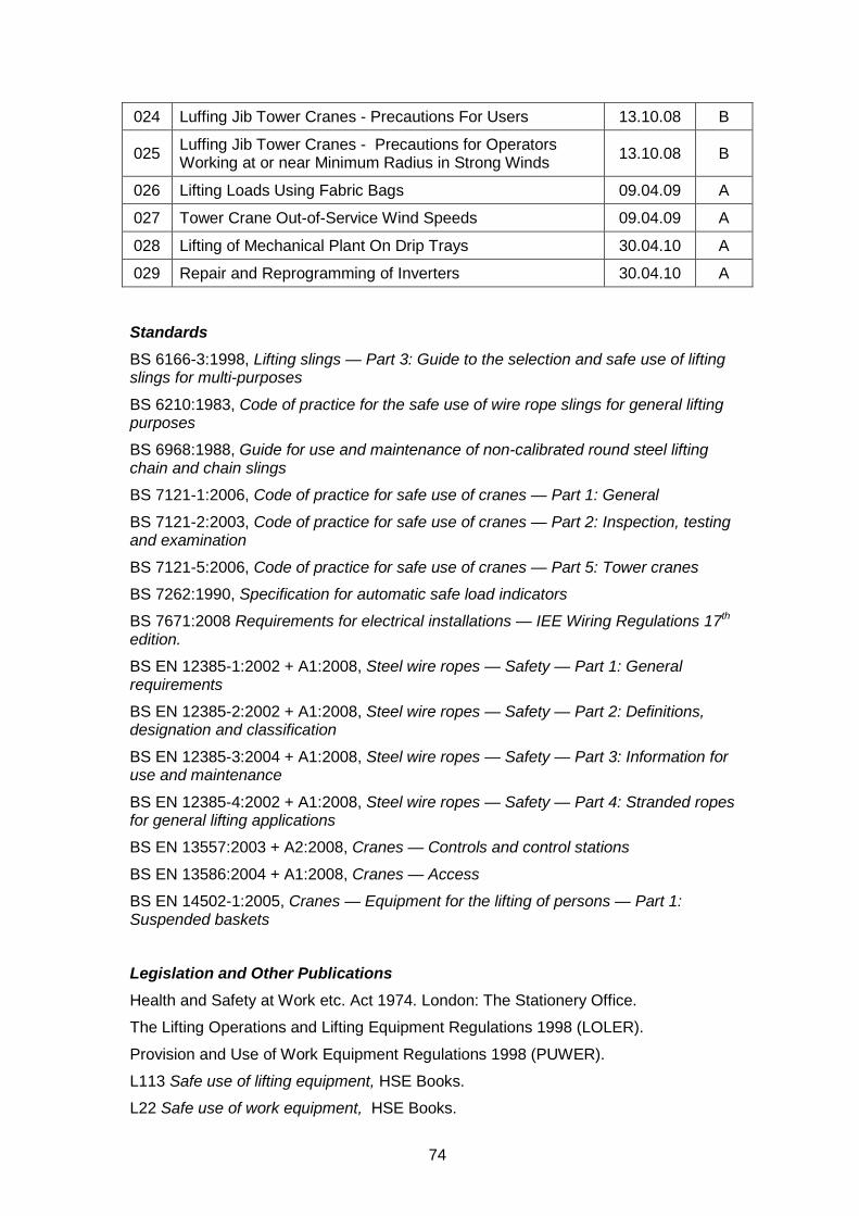
74
024 Luffing Jib Tower Cranes - Precautions For Users 13.10.08 B
025 Luffing Jib Tower Cranes - Precautions for Operators Working at or near Minimum Radius in Strong Winds 13.10.08 B
026 Lifting Loads Using Fabric Bags 09.04.09 A
027 Tower Crane Out-of-Service Wind Speeds 09.04.09 A
028 Lifting of Mechanical Plant On Drip Trays 30.04.10 A
029 Repair and Reprogramming of Inverters 30.04.10 A
Standards BS 6166-3:1998, Lifting slings — Part 3: Guide to the selection and safe use of lifting slings for multi-purposes
BS 6210:1983, Code of practice for the safe use of wire rope slings for general lifting purposes
BS 6968:1988, Guide for use and maintenance of non-calibrated round steel lifting chain and chain slings
BS 7121-1:2006, Code of practice for safe use of cranes — Part 1: General
BS 7121-2:2003, Code of practice for safe use of cranes — Part 2: Inspection, testing and examination
BS 7121-5:2006, Code of practice for safe use of cranes — Part 5: Tower cranes
BS 7262:1990, Specification for automatic safe load indicators
BS 7671:2008 Requirements for electrical installations — IEE Wiring Regulations 17th edition.
BS EN 12385-1:2002 + A1:2008, Steel wire ropes — Safety — Part 1: General requirements
BS EN 12385-2:2002 + A1:2008, Steel wire ropes — Safety — Part 2: Definitions, designation and classification
BS EN 12385-3:2004 + A1:2008, Steel wire ropes — Safety — Part 3: Information for use and maintenance
BS EN 12385-4:2002 + A1:2008, Steel wire ropes — Safety — Part 4: Stranded ropes for general lifting applications
BS EN 13557:2003 + A2:2008, Cranes — Controls and control stations
BS EN 13586:2004 + A1:2008, Cranes — Access
BS EN 14502-1:2005, Cranes — Equipment for the lifting of persons — Part 1: Suspended baskets
Legislation and Other Publications Health and Safety at Work etc. Act 1974. London: The Stationery Office.
The Lifting Operations and Lifting Equipment Regulations 1998 (LOLER).
Provision and Use of Work Equipment Regulations 1998 (PUWER).
L113 Safe use of lifting equipment, HSE Books.
L22 Safe use of work equipment, HSE Books.
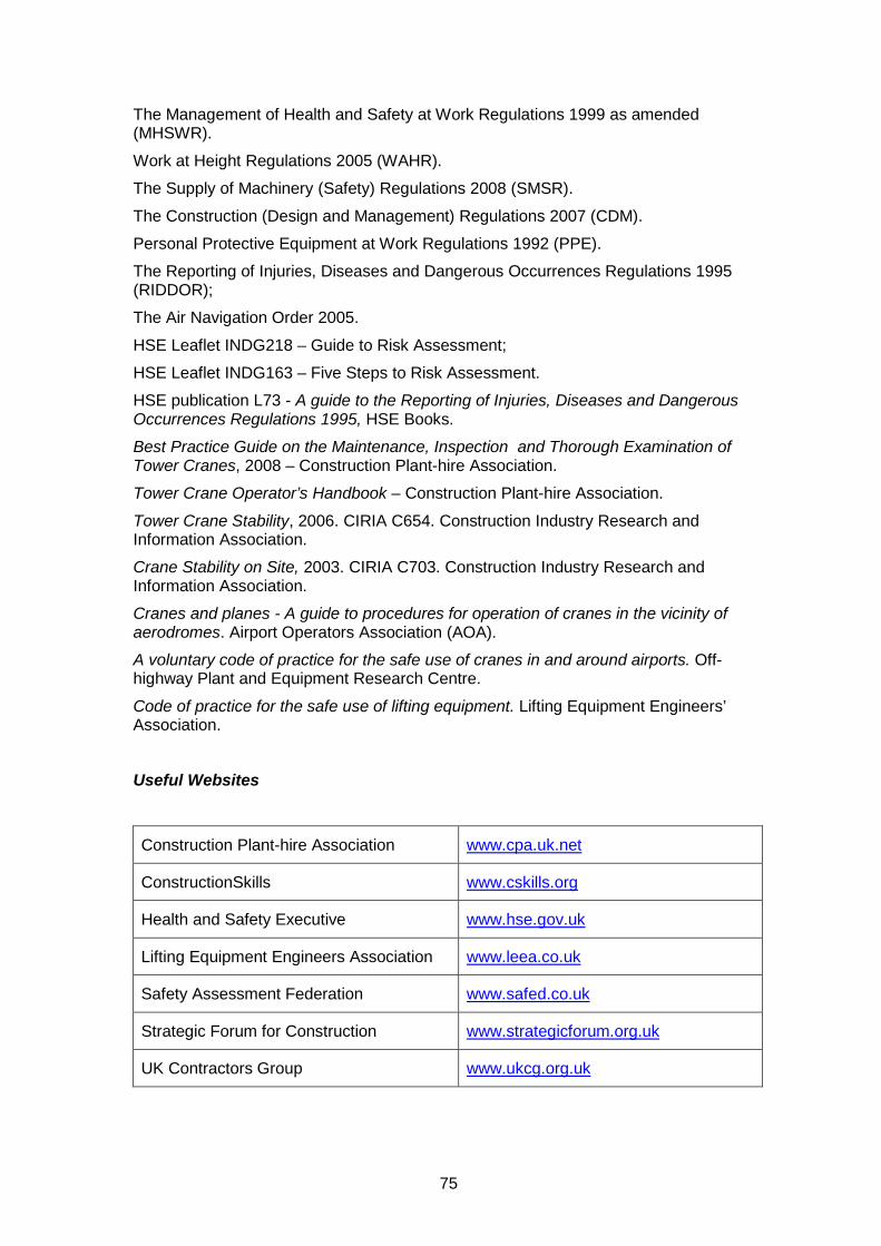
75
The Management of Health and Safety at Work Regulations 1999 as amended (MHSWR).
Work at Height Regulations 2005 (WAHR).
The Supply of Machinery (Safety) Regulations 2008 (SMSR).
The Construction (Design and Management) Regulations 2007 (CDM).
Personal Protective Equipment at Work Regulations 1992 (PPE).
The Reporting of Injuries, Diseases and Dangerous Occurrences Regulations 1995 (RIDDOR);
The Air Navigation Order 2005.
HSE Leaflet INDG218 – Guide to Risk Assessment;
HSE Leaflet INDG163 – Five Steps to Risk Assessment.
HSE publication L73 - A guide to the Reporting of Injuries, Diseases and Dangerous Occurrences Regulations 1995, HSE Books.
Best Practice Guide on the Maintenance, Inspection and Thorough Examination of Tower Cranes, 2008 – Construction Plant-hire Association.
Tower Crane Operator’s Handbook – Construction Plant-hire Association.
Tower Crane Stability, 2006. CIRIA C654. Construction Industry Research and Information Association.
Crane Stability on Site, 2003. CIRIA C703. Construction Industry Research and Information Association.
Cranes and planes - A guide to procedures for operation of cranes in the vicinity of aerodromes. Airport Operators Association (AOA).
A voluntary code of practice for the safe use of cranes in and around airports. Off-highway Plant and Equipment Research Centre.
Code of practice for the safe use of lifting equipment. Lifting Equipment Engineers’ Association.
Useful Websites
Construction Plant-hire Association www.cpa.uk.net
ConstructionSkills www.cskills.org
Health and Safety Executive www.hse.gov.uk
Lifting Equipment Engineers Association www.leea.co.uk
Safety Assessment Federation www.safed.co.uk
Strategic Forum for Construction www.strategicforum.org.uk
UK Contractors Group www.ukcg.org.uk
76
Annex N - Working Group Membership
CPA Tower Crane Interest Group – Safe Use of Self Erecting Tower Cranes – Best Practice Guide Working Group
Chairman:
S Appleyard Select Tower Cranes
Members:
K Dandridge Manitowoc Crane Group (UK) G Fisher Kier Plant Ltd D Genge Falcon Crane Hire Ltd D O’Neil Liebherr (Great Britain) Ltd I Simpson HSE Specialist Inspector H Steele Construction Plant-hire Association G Welford Arcomet Cranes Secretary & Editor:
T P Watson Construction Plant-hire Association
Working in Partnership
First Published May 2006 2nd Edition October 2006 3rd Edition May 2010 Published by:
Tower Crane Interest Group (TCIG) Construction Plant-hire Association 27/28 Newbury St London EC1A 7HU Telephone: 020 7796 3366 Email: [email protected] © CPA Copyright – 2006 & 2010