Embed Size (px)
Citation preview

8/8/2019 Guide 4 Some Important Final Things
http://slidepdf.com/reader/full/guide-4-some-important-final-things 1/20
GUIDE 4 - Some final things
TOPIC 1 MORE ON HEAT TREATED STEELS
1. NORMALISING
Temp°C
50
At 950 °C
Weight % Carbon
910
727
2
0.4 0.8 1.00.1
α-Fe + γ – FeFerrite +
γ – Fe(Austenite)
α-Fe + Fe3C(Ferrite +
α-Fe + γ – Fe(Austenite+cementite)
γ – Fe(Austenite)solidsolutiongrains
A B D50 μm CAt 20 °C
α – Fe(Ferrite)solidsolutiongrains
Coarseparticles of Fe3C (bigger
than 3μm)Pearlite
(layers of α-Fe and Fe3C)
Coarse(excess)
Fe3C
Evolution of steel microstructures
Slow cooling from austenite range
50 μm
SLOW COOLING IN AIR
“Normalising”
Samples A, B & C were tested during LAB 2.
1

8/8/2019 Guide 4 Some Important Final Things
http://slidepdf.com/reader/full/guide-4-some-important-final-things 2/20
2. HARDENING & TEMPERING
50
At 950
γ – Fe(Austenite)solidsolutiongrains
Evolution of steel microstructures“Hardening and tempering”
50 μm
Temp°C
Wei ht %
910
727
200.4 0.8 1.0
0.1
α-Fe + γ – Fe
γ – Fe(Austenite)
α-Fe + Fe3C(Ferrite +
α-Fe + γ – Fe(Austenite+ cementite)
RAPID COOLING (QUENCHING IN OIL
OR WATER)
(“Hardening”)
α’ – FeMARTENSITE – Fesupersaturated with C(microstructure sameregardless of carbon content)
At 20 °C
Tempered at 400°C
Very fine α – Fe (Ferrite) solid solution grains (~1um)
Very fine particles of Fe3C (smaller than 1μm)
A B D C
1 μm
Tempered at 600°C
1 μm
Slightly coarser α – Fe (Ferrite) solid solution grains ~3 um
Slightly coarser and fewer – more widely spaced - particles of Fe3C (smaller
than 2μm)
B* - LAB 2
2

8/8/2019 Guide 4 Some Important Final Things
http://slidepdf.com/reader/full/guide-4-some-important-final-things 3/20
UNDERSTANDING fracture toughnessCONTRAST the energy absorbed from a crack growing through:
(i) Pearlite (layered Fe3C) containing steels– refer to your NOTES !
Sample B - LAB 2
(ii) Hardened and tempered (particle Fe3C particle containing ) steels – refer toyour NOTES ! B* - LAB 2
Sample B* - LAB 2
3

8/8/2019 Guide 4 Some Important Final Things
http://slidepdf.com/reader/full/guide-4-some-important-final-things 4/20
HENCE – WE ACHIEVE THE BEST TOUGHNESS (ENERGY
ABSORBTION – AFTER TEMPERING AT 600°C – SEE LAB 2
DATA FOR SAMPLE B* & page 5)
For all steels – having more carbon in the steel microstructure means:-
1. For Normalised steels more pearlite (Fe3C palates)
2. For Hardened & tempered steels More Fe3C particles
In both cases Yield strength/proof strength, hardness & UTS (σu)
increase as the quantity of Fe3C increases. For normalised steels strength
increasing due to more Fe3C plate formation (pearlite) & ductility
(measured by the strain to fracture – εf ) deceases:- see Drawing 1 below)– also refer to Guide 1. Pure Fe3C & pure solid solution (α-Fe, called
ferrite) also shown here for reference.
1. For Normalised steels
Stress (σ)
Strain (ε)
DRAWING 1
PURE SOLIDSOLUTION α-Fe(C)
PURE COMPOUND, Fe3C
0.4% C steel
0.3% C steel
0.1% C steel
Increasing Fe 3 C plate content & increasing yield strength
Increasing α-Fe (C) content & increasing ductility (strain to fracture)
σy
σy
σy
σy
σy
εf εf εf εf εf
4

8/8/2019 Guide 4 Some Important Final Things
http://slidepdf.com/reader/full/guide-4-some-important-final-things 5/20
For Hardened & tempered steels
l hardened and tempered at different
fracture TOUGHNESS INCREASES (for the reasonsdicated on p.3).
nship/rule
.mm-2)-2
= locking parameter of grain boundaries (N.mm-3/2
)
CONSIDER A 0.4%C stee
temperatures…DRAWING 2
A range of strength, ductility & toughness can be achieved FOR THE
SAME CARBON CONTENT. In this example, the amount (volume) of
Fe3C particles does NOT change, but their size & spacing increases (seep.2) with increasing tempering temperature. Similarly, the ferrite grain
size (in H & T steels), which is always small (a few micrometres)
increases with increasing tempering temperature. Hence strength
decreases (Hall-Petch Relationship/rule) with increasing tempering
temperature, whilein
Hall-Petch Relatio
σ = yield strength of polycrystalline material (MPa/Ny
σ = yield strength of a single crysta0 l (MPa/N.mm )
d = grain diameter (size) - (m/mm)
k
Stress σ
Strain (ε)
DRAWING 2
TENSILE DATA –
Tempered at 400°C
σy
σy
σy
Tempered at 600°Csample B*
Tempered at 700°C
Quench hardenedσy
0.4%C STEELS, TEMPERED AT VARIOUSTEMPERATURES
Increasing STRENGTH
ε ε ε ε
Normalised Sam le B
Increasing α-Fe (C) grain size,increasing spacing between Fe 3 C particles and increasing ductility
σy
2 / 1−.+= d k o y σ σ
5

8/8/2019 Guide 4 Some Important Final Things
http://slidepdf.com/reader/full/guide-4-some-important-final-things 6/20
TOPIC 2 CREEP Deformation in brief
Creep is a concern for materials subjected to constant stress (below the yield strength)
at application temperatures more than about 0.3 times the absolute melting
temperature (>0.3 Tm). Window frames made of plastic deform over a couple of years unless they are reinforced with glass fibres, old fashioned lead lined window
frames and lead tiles show the same effect. More elegant examples include the creep
of Ni and Ti alloy turbine blades and fibre reinforced wind turbine blades.
There are 3 regimes of creep:-
failure
Strain
time
Drawing 1
I II
III
I – primary creep
II – secondary creep
III – tertiary creep
Unless you have designed things completely wrong, most materials find
themselves somewhere in the secondary creep regime.
6

8/8/2019 Guide 4 Some Important Final Things
http://slidepdf.com/reader/full/guide-4-some-important-final-things 7/20
Strain
time
Drawing 2
The arrow shown in drawing 2 indicates the effect on creep rates when
temperature and/or the applied force is increased.
Limiting creep deformation is based on controlling material
micro/macrostructutes.
For alloys this means:
• Maximising the grain size – possibly use single crystals, e.g., some
gas turbine blades
• Controlling the grain orientation to prevent plastic flow
• Increase the stress needed to cause creep deformation by increasing
the compund content of the alloy
• Preventing grain boundary sliding/rotation by causing very fine
(nanometre sized) compound formation on the solid solution grain
boundaries – this causes a type of grain boundary “pinning”.
Also refer to the handout (see pdf file) – circulated earlier this year - on
some research work aimed at developing Mg alloys for creep
applications.
7

8/8/2019 Guide 4 Some Important Final Things
http://slidepdf.com/reader/full/guide-4-some-important-final-things 8/20
TOPIC 3 MORE ON POLYMERS
Here’s a reminder of what happens to the amorphous chain
structure of a simple polymer during tensile testing (no
crystallites in these materials).
POLYMER CHAINS REARRANGED
IN DIRECTION OF APPLIED
STRESS
σσ
RANDOMLY
ARRANGED CHAINS
(NON‐DEFORMED PART OF
TEST‐PIECE)
8

8/8/2019 Guide 4 Some Important Final Things
http://slidepdf.com/reader/full/guide-4-some-important-final-things 9/20
Now consider the same material again taken to the point of
fracture and let’s contrast this with what happens to a semi-
crystalline polymer. Semi-crystalline polymers contain (i) the
usual amorphous chains and (ii) “crystallites”. The latter are
tightly folded chains with a high Young’s modulus (maybe
220GPa) compared to about 1 GPa for the amorphous material.
Here’s what happens to both structures during plastic deformation
(of course this is above Tg when plastic deformation is possible).
Applied shear
Chains & crystallites rotate
in direction of shear Randomly oriented chains &
crystallites
Crystallites
vertically align
to form
“micro‐fibrils”
Fracture
Chains & un‐tangle
in direction of shear
Amorphous polymers
Semi‐crystalline
Applied shear
REGARDLESS OF THE POLYMER TYPE a critical chain length is
required to enable their structures to “hang together” during plastic
deformation – remember the demo/ with the string !
The Young’s moduli of Semi-crystalline polymers can be modelled using
composite rules. In fact they follow ISOSTRESS behaviour (see Guide3):-
⎥⎦
⎤⎢⎣
⎡+⎥
⎦
⎤⎢⎣
⎡=
⎥⎥⎦
⎤
⎢⎢⎣
⎡
2
2
1
11
P
V
P
V
PComposite
Here, P = property or parameter (e.g., hardness, Young’s modulus etc) and the subscripts 1 and 2
refer to phases 1 & 2 or components 1 & 2. So we can rewrite this as:-
⎥⎥⎦
⎤
⎢⎢⎣
⎡+
⎥⎦
⎤
⎢⎣
⎡=
⎥⎥⎦
⎤
⎢⎢⎣
⎡
− cryst
cryst
amor
amor
polcryst semi E
V
E
V
E .
1
9

8/8/2019 Guide 4 Some Important Final Things
http://slidepdf.com/reader/full/guide-4-some-important-final-things 10/20
TOPIC 4 - MORE ON INTERFACES AND
BOUNDARIES
MANY TIMES WE HAVE STATED:
1. Solid solutions are TOUGH
2. Compounds are BRITTLE
FURTHERMORE THE BUILDING BLOCKS OF AN ALLOY ARE:
MIXES of solid solutions and compounds.
WE DISCOVERED IN THE LECTURES THAT
3. Phase boundaries and grain boundaries are very important too !
SUMMARY of the “LATEST” NEWS
Grain boundaries in pure metals and pure (clean) alloys
ARE TOUGH
PHASE boundaries between
(i) Ceramics and metals
(ii) solid solutions and compounds
ARE VERY BRITTLE
This explains WHY compound SHAPE and SIZE is so important in influencing
FRACTURE TOUGHNESS !
SOMETHING NEW Grain boundaries in pure ceramics
ARE ALSO BRITTLE
10

8/8/2019 Guide 4 Some Important Final Things
http://slidepdf.com/reader/full/guide-4-some-important-final-things 11/20
TOPIC 4 MORE ON CERAMICS
CERAMICS AT
ROOM TEMPERATURE BRITTLE
Obey the Griffith’s Equation
GRIFFITH’S
EQUATION
σf = FRACTURE
STRESS (M.Pa)
E = YOUNG'S
MODULUS (G.Pa)
γ = WORK TO
FRACTURE (J/m2
)
c = DEFECT RADIUS (m)
FLAWS/DEFECTS ORIGINATE FROM
PROCESSING
NOTE: WHEN CERAMICS ARE DEFECT FREE σy ~ σf
[σy = YIELD STRENGTH]
11

8/8/2019 Guide 4 Some Important Final Things
http://slidepdf.com/reader/full/guide-4-some-important-final-things 12/20
γ (WORK TO FRACTURE)
FOR CERAMICS γ ~ 10 J/m2
SODA GLASS γ ~ 5 J/m2
FOR METALS γ ~ 103
TO 106
J/m2
(Compare these figures with your own data obtained
from Labs 1 and 2 !)CRACK TIP (METALS)
PLASTIC ZONE ABSORBS ENERGY OF
ADVANCING CRACK
CRACK TIP (CERAMICS)
LITTLE OR NO
PLASTIC ZONE LITTLE ENERGY
ABSORPTION
12
8/8/2019 Guide 4 Some Important Final Things
http://slidepdf.com/reader/full/guide-4-some-important-final-things 13/20
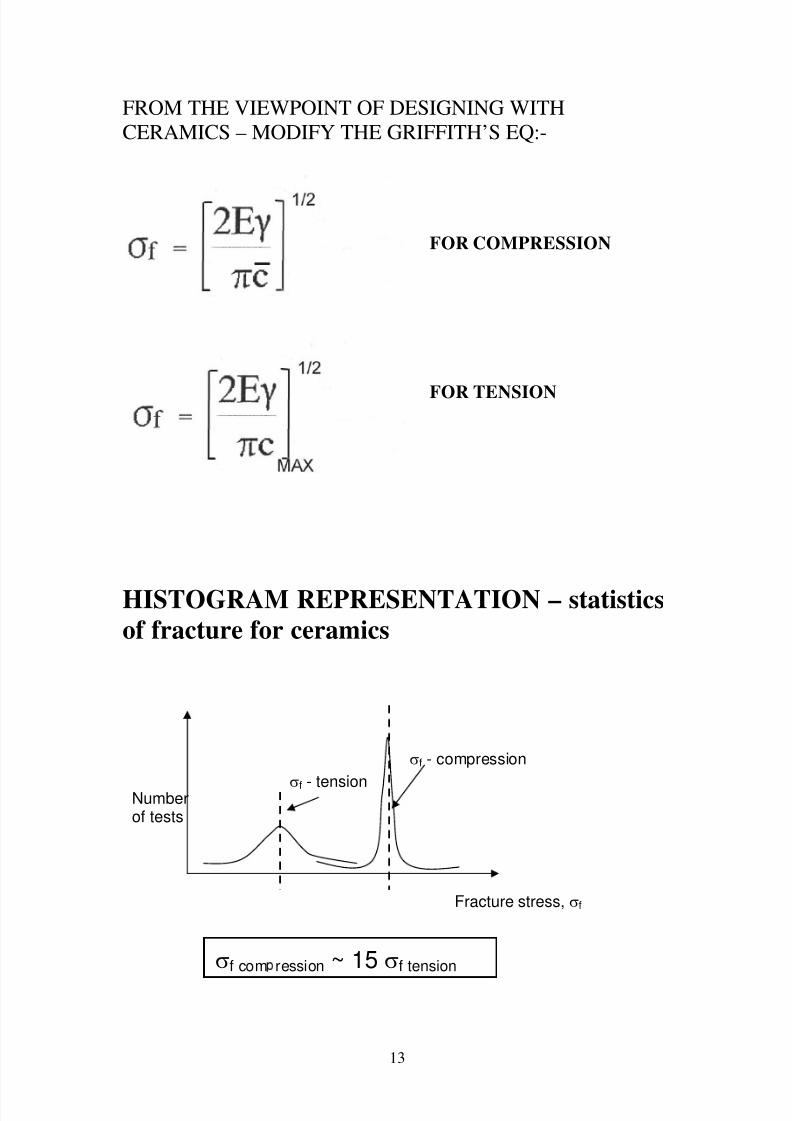
FROM THE VIEWPOINT OF DESIGNING WITH
CERAMICS – MODIFY THE GRIFFITH’S EQ:-
FOR COMPRESSION
FOR TENSION
HISTOGRAM REPRESENTATION – statistics
of fracture for ceramics
Numberof tests
Fracture stress, σf
σf - tension
σf - compression
σf com ression ~ 15 σf tension
13

8/8/2019 Guide 4 Some Important Final Things
http://slidepdf.com/reader/full/guide-4-some-important-final-things 14/20
IN COMPRESSION CRACKS PROPAGATE
STABLY
ON APPLICATION OF
STRESS CRACKS "TWIST-
OUT" OF ORIGINAL
ORIENTATION -
ALIGN PARALLEL TO
AXIS
OF APPLIED STRESS
IN COMPRESSION
FAILURE
PROCEEDS VIA
PROGRESSIVECRUSHING
"CRUSHED
ZONE” FORMS
FOLLOWED BY
COLLAPSE
[NOTE: "c" IN EQUATION 1, WILL BE AVERAGE VALUE
IN THIS CASE]
HENCE, THERE WILL BE A DEFINITE "WARNING”
OF FAILURE
14

8/8/2019 Guide 4 Some Important Final Things
http://slidepdf.com/reader/full/guide-4-some-important-final-things 15/20
IN TENSION FAILURE IS SUDDEN
AND CATASTROPHIC (NO
WARNING)
[NOTE: "c" IN EQUATION 1, WILL BE MAXIMUM VALUE IN THIS
CASE]
15

8/8/2019 Guide 4 Some Important Final Things
http://slidepdf.com/reader/full/guide-4-some-important-final-things 16/20
THE MINIMISATION OF DEFECTS AND
PORES IN CERAMICS
TYPICAL MICROSTRUCTURE OF A CERAMIC
SHOWING GRAINS AND DEFECTS
TECHNICALCERAMICS PRODUCED FROM
POWDERS
TO ACHIEVE ~95-99% DENSITY – TWO MAIN STEPS:
(A) COLD PRESSING
MIX POWDER WITH WAX
COLD PRESS POWDER IN RIGID DIE
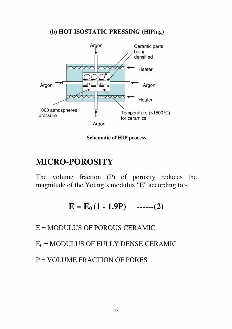
(B) HIGH TEMPERATURE DIFFUSION BONDING
"FIRE" OR "SINTER" >1500ºC
16

8/8/2019 Guide 4 Some Important Final Things
http://slidepdf.com/reader/full/guide-4-some-important-final-things 17/20
MINIMISE “c” INCLUDE:-
(1) ONLY ULTRA-FINE (<1µm) POWDERS
(2) "CLEAN ROOM" CONDITIONS
(3) APPLY PRESSURE DURING SEOND STAGE (HIGH
TEMPERATURE)
(a) HOT PRESSING (~ 30 M.Pa)
17
8/8/2019 Guide 4 Some Important Final Things
http://slidepdf.com/reader/full/guide-4-some-important-final-things 18/20

8/8/2019 Guide 4 Some Important Final Things
http://slidepdf.com/reader/full/guide-4-some-important-final-things 19/20
Here is a plot using Equation 2 for three typical Engineering
ceramic materials. As the AMOUNT of porosity decreases E
proportionately decreases…
FROM EQUATIONS 1 AND 2
We can deduce that if we want MAXIMISE the fracture
strength (σf ) of a ceramic we must:
MAXIMISE E
MINIMISE c
MINIMISE P
19

8/8/2019 Guide 4 Some Important Final Things
http://slidepdf.com/reader/full/guide-4-some-important-final-things 20/20
Here’s a typical numerical problem based on the Griffith’s equations
and other relationships given in this short guide on ceramics
An Al2O3 ceramic contains defects (pores) with an average diameter0.96μm and with a density that is 97.5% of the theoretical value, i.e., the
ceramic contains 2.5 volume % porosity. Based on this data and by
applying the appropriate equation(s) determine the fracture strength of
the ceramic in (i) tension and; (ii) compression. (The theoretical value
of the Young’s modulus for Al2O3 ceramic is 400 GPa. Assume the
work to fracture is 10 J/m2.)
Strategy:
FIRST Determine the Young’s modulus (E) of the porous ceramic via
equation 2
E = E0 (1 - 1.9P)
obviously here P=0.025 & E0=400GPa
SECOND Determine the fracture strength of the ceramic in compression.
We are given the average pore daimeter (2c = 0.96 x 10⁻⁶
m so
c=0.48x10⁻⁶
m). Next all we need do is to rearrange the appropriateversion of the Griffiths’s equation (for compression) and insert the value
of 10 J/m2 for the work to fracture. Take care here to keep the E units in
N/m2.
THIRD Convert your compressive fracture strength into a tensilestrength via the rule of thumb relationship:
σf compression ~ 15 σf tension
SIMPLE !
THE END