Embed Size (px)
Citation preview
Advanced Output CenterSullivan Center, Rm. 1232
312 629 6688 / [email protected] document is available electronically at http://crit.artic.edu/aoc
Page: 1 of 19 Last Modified: June 9, 2017 1:49 PM
Handyscan REVScanMinimum Size
Maximum Size
Resolution
AccuracyTexture Capture
Material
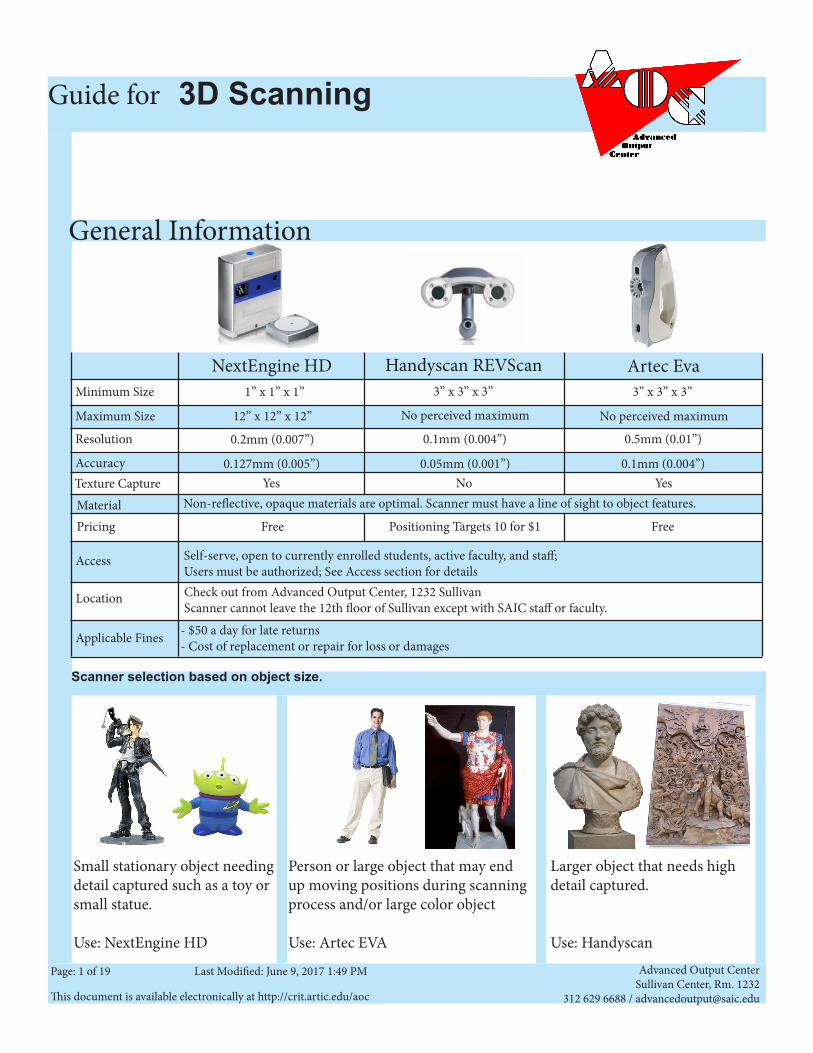
NextEngine HD Artec Eva1” x 1” x 1” 3” x 3” x 3” 3” x 3” x 3”
12” x 12” x 12” No perceived maximum No perceived maximum
0.2mm (0.007”) 0.1mm (0.004”) 0.5mm (0.01”)
Yes No YesNon-reflective, opaque materials are optimal. Scanner must have a line of sight to object features.
0.127mm (0.005”) 0.05mm (0.001”) 0.1mm (0.004”)
Pricing Free Positioning Targets 10 for $1 Free
Access
Applicable Fines
Self-serve, open to currently enrolled students, active faculty, and staff;Users must be authorized; See Access section for details
- $50 a day for late returns- Cost of replacement or repair for loss or damages
Location Check out from Advanced Output Center, 1232 SullivanScanner cannot leave the 12th floor of Sullivan except with SAIC staff or faculty.
Guide for 3D Scanning
General Information
Scanner selection based on object size.
Small stationary object needing detail captured such as a toy or small statue.
Use: NextEngine HD
Person or large object that may end up moving positions during scanning process and/or large color object
Use: Artec EVA
Larger object that needs high detail captured.
Use: Handyscan
Advanced Output CenterSullivan Center, Rm. 1232
312 629 6688 / [email protected] document is available electronically at http://crit.artic.edu/aoc
Page: 2 of 19 Last Modified: June 9, 2017 1:49 PM
Accessing the 3D Scanners Authorizations
Reservations
Walk-ins
Special Conditions
• Before using the 3D scanners, you must first attend an authorization session at the AOC. Currently enrolled students, faculty and staff can be authorized for 3D scanning.
• The information covered during authorizations will change as software and hardware are updated or reconfigured. To keep users up to date on 3D scanning techniques and policies, authorizations will be good for one calendar year, after which you will need to be re-authorized.
• View the authorization schedule and sign up online: crit.artic.edu/aoc
• Reservations must be made in person through a lab monitor at least 12 hours before the time being reserved, and no more than 2 weeks in advance.
• Reservations are non-transferable from one person to another. You can only make and use reservations for yourself. • Reservations can be rescheduled if you notify the AOC at least 3 hours in advance of your reserved timeslot. • You will be given a 10-minute grace period to show up for your reserved time slot. After the grace period expires, your slot will
become available for walk-in users.• In the unlikely event that your reserved time slot must be canceled due to equipment malfunction or other
unforesee-able issues, you will be notified as quickly as possible and given the option to make a new reservation at the earliest available time slot.
• In the event that a 3D scanner is taken offline, it will not be available for reservation until it is operational again.
• All authorized users are able to walk in and use any 3D scanner when it has not been reserved in advance, or when a no-show for a reservation occurs. Walk-in users must check in with a lab monitor prior to scanning.
• Walk-in users can use as much time as is available, up to when the next reservation starts or 30 minutes before the AOC closes, whichever comes first.
• The 3D scanner can NOT leave the 12th floor of the Sullivan building without SAIC staff or faculty accompanying the scanner. • Late returns will be fined $50/day. • The 3D scanner must be returned the same day it is checked out, half an hour before the AOC closes.
Advanced Output CenterSullivan Center, Rm. 1232
312 629 6688 / [email protected] document is available electronically at http://crit.artic.edu/aoc
Page: 3 of 19 Last Modified: June 9, 2017 1:49 PM
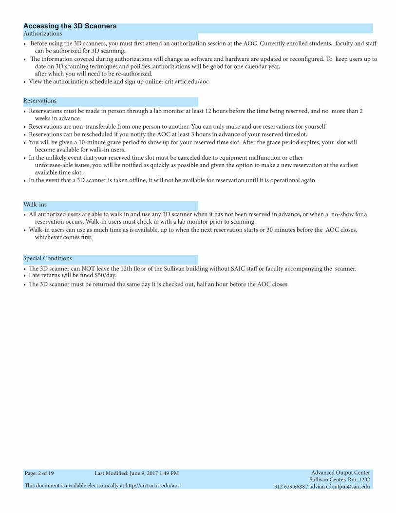
Artec Eva 3D Scanner Artec Eva Contents:
Artec Eva• Artec Eva• Power Supply• Power Supply cable• 2 connected USB cords• Case(not pictured)
Dell Laptop• Dell laptop• Laptop Case(not pictured)• Power Supply cable• mouse
Optional Artec External Battery
• The Artec has an added option of using a portable rechargeable battery. This can be useful if you are scanning in an area without access to a wall outlet.
• If you are interested in this option, try to let the AOC know ahead of time through email or in person so we can have both the battery and laptop at full charge for you.
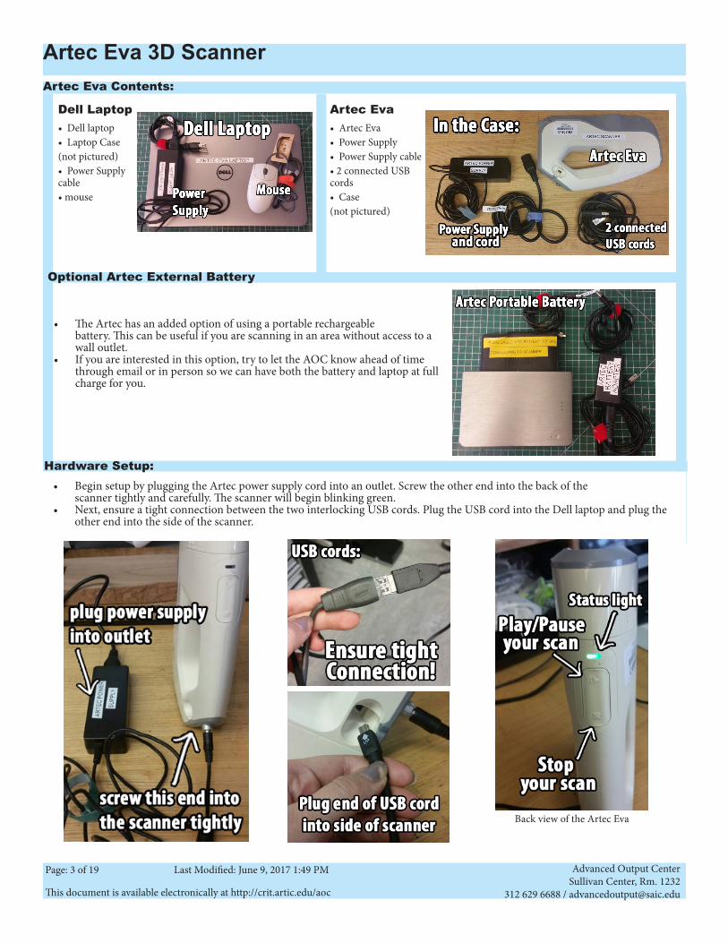
• Begin setup by plugging the Artec power supply cord into an outlet. Screw the other end into the back of the scanner tightly and carefully. The scanner will begin blinking green.
• Next, ensure a tight connection between the two interlocking USB cords. Plug the USB cord into the Dell laptop and plug the other end into the side of the scanner.
Hardware Setup:
Back view of the Artec Eva
Advanced Output CenterSullivan Center, Rm. 1232
312 629 6688 / [email protected] document is available electronically at http://crit.artic.edu/aoc
Page: 4 of 19 Last Modified: June 9, 2017 1:49 PM
Artec Studio 9 Overview
Handling the Artec Eva
• The Artec Eva is a lightweight hand-held device, be very careful to set it down away from the edges of the table or platform you are working on as it does not have a cradle to rest in when not in use.
• The Artec is not cordless so you must be mindful of tripping hazards. • On the front face of the Artec, you have two cameras and circular lightsource. Do not directly touch any of these areas. If they
appear dirty, alert an AOC staff member - do not attempt to clean.
• Using the scan software requires a lot of memory. It is highly recommended you close out all other applications before beginning.
• Open Artec Studio 9. Before you begin, you may want to save your project from the “file” menu so you can continue to save your work as you progress.
• Keep in mind that as your project grows with more and more scans, it will take much longer to save. Do not try to save every-thing from your whole session at once. These scanners are due back 30 minutes before closing - no exceptions.
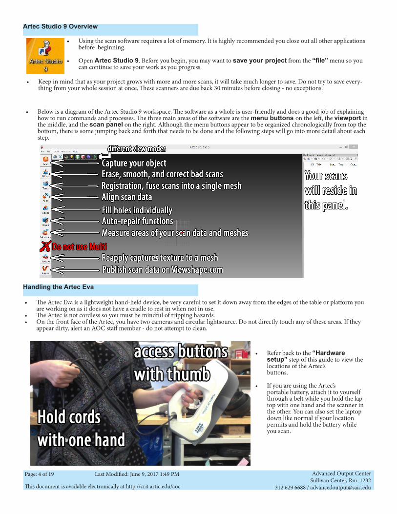
• Below is a diagram of the Artec Studio 9 workspace. The software as a whole is user-friendly and does a good job of explaining how to run commands and processes. The three main areas of the software are the menu buttons on the left, the viewport in the middle, and the scan panel on the right. Although the menu buttons appear to be organized chronologically from top the bottom, there is some jumping back and forth that needs to be done and the following steps will go into more detail about each step.
• Refer back to the “Hardware setup” step of this guide to view the locations of the Artec’s buttons.
• If you are using the Artec’s portable battery, attach it to yourself through a belt while you hold the lap-top with one hand and the scanner in the other. You can also set the laptop down like normal if your location permits and hold the battery while you scan.
Advanced Output CenterSullivan Center, Rm. 1232
312 629 6688 / [email protected] document is available electronically at http://crit.artic.edu/aoc
Page: 5 of 19 Last Modified: June 9, 2017 1:49 PM
Configure the Artec Eva in Artec Studio 9
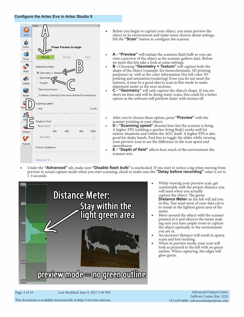
• Before you begin to capture your object, you must preview the object in its environment and make some choices about settings. Hit the “Scan” button to configure the scanner.
• A - “Preview” will initiate the scanners flash bulb so you can view a preview of the object as the scanner gathers data. Before we press this lets take a look at some settings.
• B - Choosing “Geometry + Texture” will capture both the shape of the object (example: for monochromatic 3D printing purposes) as well as the color information (for full color 3D printing and animation/rendering) Even you do not need the textures, it may be a good idea to scan in this mode to make alignment easier in the next sections.
• C - “Geometry” will only capture the object’s shape. If you are short on time and will be doing many scans, this could be a better option as the software will perform faster with texture off.
• After you’ve chosen these option, press “Preview” with the scanner pointing at your object.
• D - “Scanning speed” denotes how fast the scanner is firing. A higher FPS (yielding a quicker firing flash) works well for indoor situations and within the AOC itself. A higher FPS is also good for shaky hands. Feel free to toggle the slider while viewing your preview scan to see the difference in the scan speed and smoothness.
• E - “Depth of field” affects how much of the environment the scanner sees.
• Under the “Advanced” tab, make sure “Disable flash bulb” is unchecked. If you start to notice a lag when moving from preview to actual capture mode when you start scanning, check to make sure the “Delay before recording” value is set to 1-3 seconds.
• While viewing your preview scan, get comfortable with the proper distance you will need when you actually capture the object. The green Distance Meter on the left will aid you in this. You want most of your data curve to reside in the lightest green area of the meter.
• Move around the object with the scanner pointed at it and observe the meter mak-ing sure you have ample room to capture the object optimally in the environment you are in.
• An incorrect distance will result in sparse scans and lost tracking.
• When in preview mode, your scan will look as pictured to the left with no green outline. When capturing, the edges will glow green.
Advanced Output CenterSullivan Center, Rm. 1232
312 629 6688 / [email protected] document is available electronically at http://crit.artic.edu/aoc
Page: 6 of 19 Last Modified: June 9, 2017 1:49 PM
Scanning in Artec Studio 9
Editing your scan - Erasing
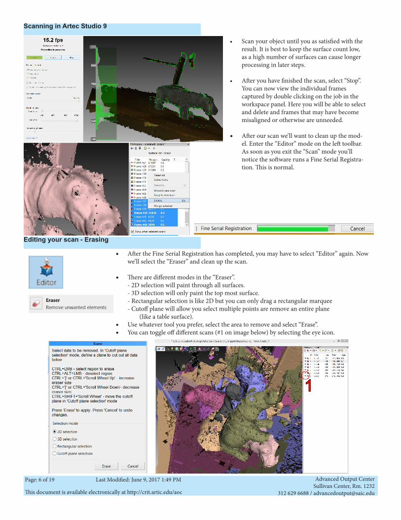
• Scan your object until you as satisfied with the result. It is best to keep the surface count low, as a high number of surfaces can cause longer processing in later steps.
• After you have finished the scan, select “Stop”. You can now view the individual frames captured by double clicking on the job in the workspace panel. Here you will be able to select and delete and frames that may have become misaligned or otherwise are unneeded.
• After our scan we’ll want to clean up the mod-el. Enter the “Editor” mode on the left toolbar. As soon as you exit the “Scan” mode you’ll notice the software runs a Fine Serial Registra-tion. This is normal.
• After the Fine Serial Registration has completed, you may have to select “Editor” again. Now we’ll select the “Eraser” and clean up the scan.
• There are different modes in the “Eraser”. - 2D selection will paint through all surfaces. - 3D selection will only paint the top most surface. - Rectangular selection is like 2D but you can only drag a rectangular marquee - Cutoff plane will allow you select multiple points are remove an entire plane (like a table surface).
• Use whatever tool you prefer, select the area to remove and select “Erase”.• You can toggle off different scans (#1 on image below) by selecting the eye icon.
Advanced Output CenterSullivan Center, Rm. 1232
312 629 6688 / [email protected] document is available electronically at http://crit.artic.edu/aoc
Page: 7 of 19 Last Modified: June 9, 2017 1:49 PM
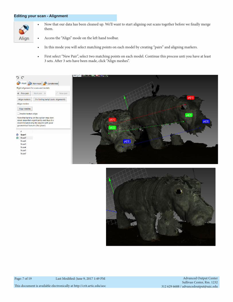
• Now that our data has been cleaned up. We’ll want to start aligning out scans together before we finally merge them.
• Access the “Align” mode on the left hand toolbar.
• In this mode you will select matching points on each model by creating “pairs” and aligning markers.
• First select “New Pair”, select two matching points on each model. Continue this process unti you have at least 3 sets. After 3 sets have been made, click “Align meshes”.
Editing your scan - Alignment
Advanced Output CenterSullivan Center, Rm. 1232
312 629 6688 / [email protected] document is available electronically at http://crit.artic.edu/aoc
Page: 8 of 19 Last Modified: June 9, 2017 1:49 PM
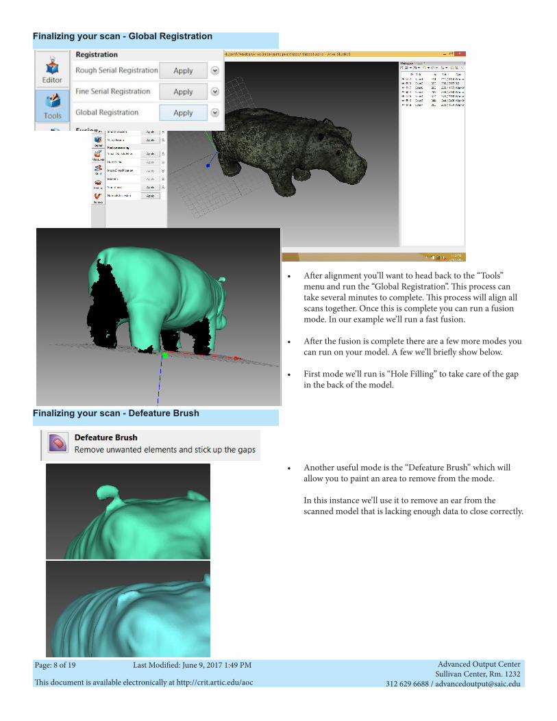
Finalizing your scan - Global Registration
Finalizing your scan - Defeature Brush
• After alignment you’ll want to head back to the “Tools” menu and run the “Global Registration”. This process can take several minutes to complete. This process will align all scans together. Once this is complete you can run a fusion mode. In our example we’ll run a fast fusion.
• After the fusion is complete there are a few more modes you can run on your model. A few we’ll briefly show below.
• First mode we’ll run is “Hole Filling” to take care of the gap in the back of the model.
• Another useful mode is the “Defeature Brush” which will allow you to paint an area to remove from the mode. In this instance we’ll use it to remove an ear from the scanned model that is lacking enough data to close correctly.
Advanced Output CenterSullivan Center, Rm. 1232
312 629 6688 / [email protected] document is available electronically at http://crit.artic.edu/aoc
Page: 9 of 19 Last Modified: June 9, 2017 1:49 PM
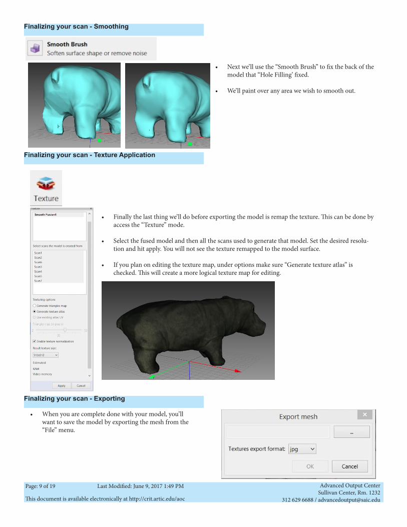
• Next we’ll use the “Smooth Brush” to fix the back of the model that “Hole Filling’ fixed.
• We’ll paint over any area we wish to smooth out.
• Finally the last thing we’ll do before exporting the model is remap the texture. This can be done by access the “Texture” mode.
• Select the fused model and then all the scans used to generate that model. Set the desired resolu-tion and hit apply. You will not see the texture remapped to the model surface.
• If you plan on editing the texture map, under options make sure “Generate texture atlas” is checked. This will create a more logical texture map for editing.
• When you are complete done with your model, you’ll want to save the model by exporting the mesh from the “File” menu.
Finalizing your scan - Smoothing
Finalizing your scan - Texture Application
Finalizing your scan - Exporting
Advanced Output CenterSullivan Center, Rm. 1232
312 629 6688 / [email protected] document is available electronically at http://crit.artic.edu/aoc
Page: 10 of 19 Last Modified: June 9, 2017 1:49 PM
Handyscan Object Preparation
Macbook Pro • Macbook Pro• Laptop Case (Not Pictured) • Power Supply • Mouse
Handyscan • Handyscan • FireWire Cable • Firewire Adapter (labeled “HS”)• Power Supply• Stand • Case (not pictured) • Positioning targets or stickered board
HandyScan REVscan G2:
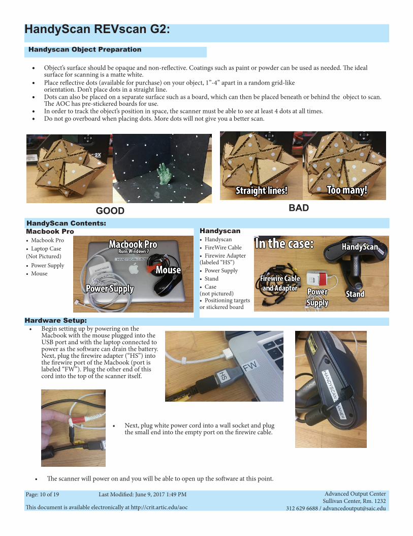
• Object’s surface should be opaque and non-reflective. Coatings such as paint or powder can be used as needed. The ideal surface for scanning is a matte white.
• Place reflective dots (available for purchase) on your object, 1”-4” apart in a random grid-like orientation. Don’t place dots in a straight line.
• Dots can also be placed on a separate surface such as a board, which can then be placed beneath or behind the object to scan. The AOC has pre-stickered boards for use.
• In order to track the object’s position in space, the scanner must be able to see at least 4 dots at all times. • Do not go overboard when placing dots. More dots will not give you a better scan.
• Begin setting up by powering on the Macbook with the mouse plugged into the USB port and with the laptop connected to power as the software can drain the battery. Next, plug the firewire adapter (“HS”) into the firewire port of the Macbook (port is labeled “FW”). Plug the other end of this cord into the top of the scanner itself.
• Next, plug white power cord into a wall socket and plug the small end into the empty port on the firewire cable.
• The scanner will power on and you will be able to open up the software at this point.
GOOD BADHandyScan Contents:
Hardware Setup:
Advanced Output CenterSullivan Center, Rm. 1232
312 629 6688 / [email protected] document is available electronically at http://crit.artic.edu/aoc
Page: 11 of 19 Last Modified: June 9, 2017 1:49 PM
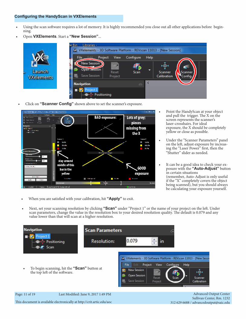
Configuring the HandyScan in VXElements
• Using the scan software requires a lot of memory. It is highly recommended you close out all other applications before begin-ning.
• Open VXElements. Start a “New Session”...
• Click on “Scanner Config” shown above to set the scanner’s exposure.
• Point the HandyScan at your object and pull the trigger. The X on the screen represents the scanner’s laser-crosshairs. For ideal exposure, the X should be completely yellow or close as possible.
• Under the “Scanner Parameters” panel on the left, adjust exposure by increas-ing the “Laser Power” first, then the “Shutter” slider as needed.
• It can be a good idea to check your ex-posure with the “Auto-Adjust” button in certain situations (remember, Auto-Adjust is only useful if the “X” completely covers the object being scanned), but you should always be calculating your exposure yourself.
• To begin scanning, hit the “Scan” button at the top left of the software.
• Next, set your scanning resolution by clicking “Scan” under “Project 1” or the name of your project on the left. Under scan parameters, change the value in the resolution box to your desired resolution quality. The default is 0.079 and any value lower than that will scan at a higher resolution.
• When you are satisfied with your calibration, hit “Apply” to exit.
Advanced Output CenterSullivan Center, Rm. 1232
312 629 6688 / [email protected] document is available electronically at http://crit.artic.edu/aoc
Page: 12 of 19 Last Modified: June 9, 2017 1:49 PM
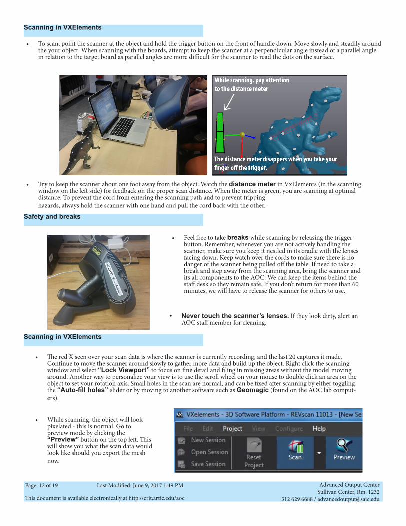
• Try to keep the scanner about one foot away from the object. Watch the distance meter in VxElements (in the scanning window on the left side) for feedback on the proper scan distance. When the meter is green, you are scanning at optimal distance. To prevent the cord from entering the scanning path and to prevent tripping hazards, always hold the scanner with one hand and pull the cord back with the other.
• The red X seen over your scan data is where the scanner is currently recording, and the last 20 captures it made. Continue to move the scanner around slowly to gather more data and build up the object. Right click the scanning window and select “Lock Viewport” to focus on fine detail and filing in missing areas without the model moving around. Another way to personalize your view is to use the scroll wheel on your mouse to double click an area on the object to set your rotation axis. Small holes in the scan are normal, and can be fixed after scanning by either toggling the “Auto-fill holes” slider or by moving to another software such as Geomagic (found on the AOC lab comput-ers).
• To scan, point the scanner at the object and hold the trigger button on the front of handle down. Move slowly and steadily around the your object. When scanning with the boards, attempt to keep the scanner at a perpendicular angle instead of a parallel angle in relation to the target board as parallel angles are more difficult for the scanner to read the dots on the surface.
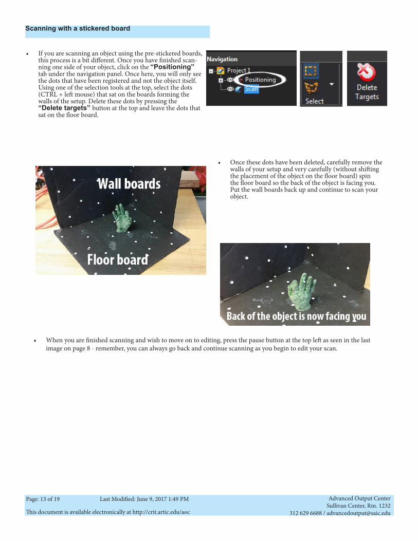
• Feel free to take breaks while scanning by releasing the trigger button. Remember, whenever you are not actively handling the scanner, make sure you keep it nestled in its cradle with the lenses facing down. Keep watch over the cords to make sure there is no danger of the scanner being pulled off the table. If need to take a break and step away from the scanning area, bring the scanner and its all components to the AOC. We can keep the items behind the staff desk so they remain safe. If you don’t return for more than 60 minutes, we will have to release the scanner for others to use.
• While scanning, the object will look pixelated - this is normal. Go to preview mode by clicking the “Preview” button on the top left. This will show you what the scan data would look like should you export the mesh now.
Scanning in VXElements
• Never touch the scanner’s lenses. If they look dirty, alert an AOC staff member for cleaning.
Safety and breaks
Scanning in VXElements
Advanced Output CenterSullivan Center, Rm. 1232
312 629 6688 / [email protected] document is available electronically at http://crit.artic.edu/aoc
Page: 13 of 19 Last Modified: June 9, 2017 1:49 PM
• When you are finished scanning and wish to move on to editing, press the pause button at the top left as seen in the last image on page 8 - remember, you can always go back and continue scanning as you begin to edit your scan.
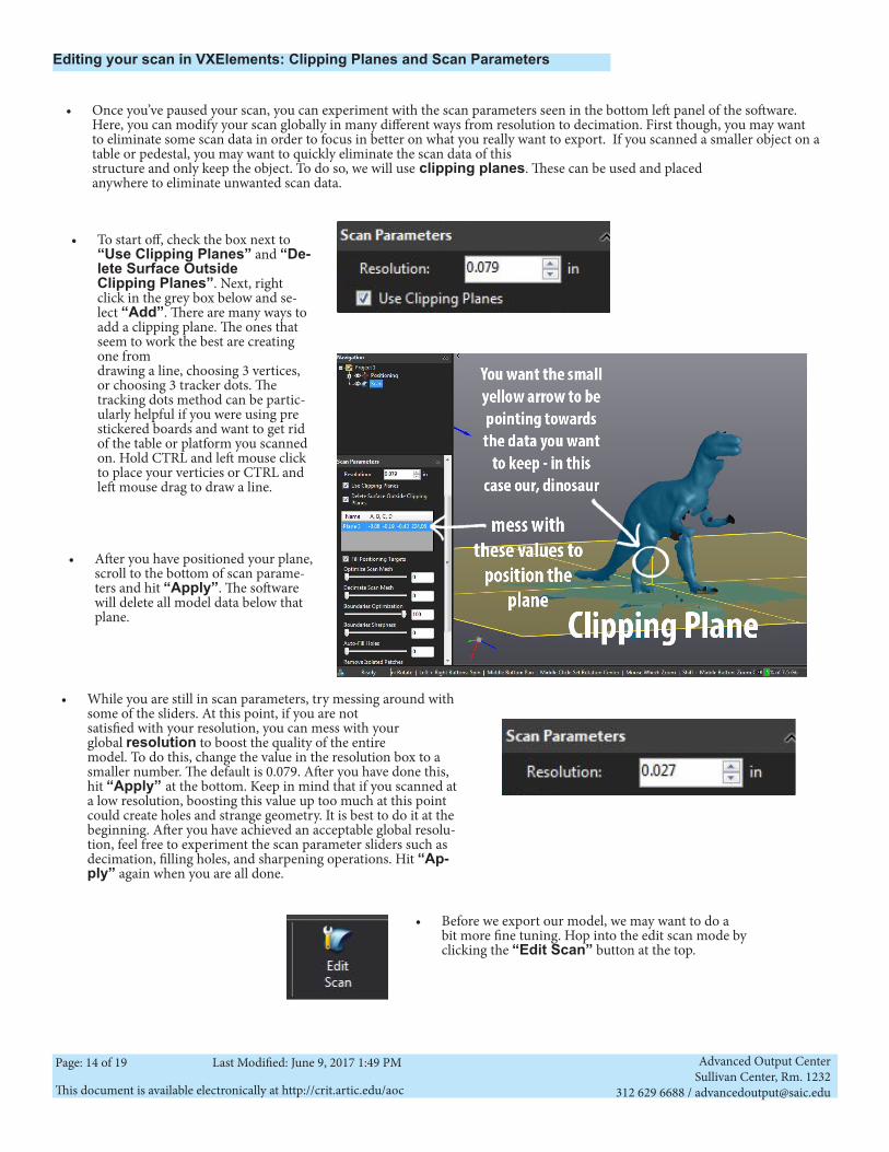
• If you are scanning an object using the pre-stickered boards, this process is a bit different. Once you have finished scan-ning one side of your object, click on the “Positioning” tab under the navigation panel. Once here, you will only see the dots that have been registered and not the object itself. Using one of the selection tools at the top, select the dots (CTRL + left mouse) that sat on the boards forming the walls of the setup. Delete these dots by pressing the “Delete targets” button at the top and leave the dots that sat on the floor board.
• Once these dots have been deleted, carefully remove the walls of your setup and very carefully (without shifting the placement of the object on the floor board) spin the floor board so the back of the object is facing you. Put the wall boards back up and continue to scan your object.
Scanning with a stickered board
Advanced Output CenterSullivan Center, Rm. 1232
312 629 6688 / [email protected] document is available electronically at http://crit.artic.edu/aoc
Page: 14 of 19 Last Modified: June 9, 2017 1:49 PM
• Once you’ve paused your scan, you can experiment with the scan parameters seen in the bottom left panel of the software. Here, you can modify your scan globally in many different ways from resolution to decimation. First though, you may want to eliminate some scan data in order to focus in better on what you really want to export. If you scanned a smaller object on a table or pedestal, you may want to quickly eliminate the scan data of this structure and only keep the object. To do so, we will use clipping planes. These can be used and placed anywhere to eliminate unwanted scan data.
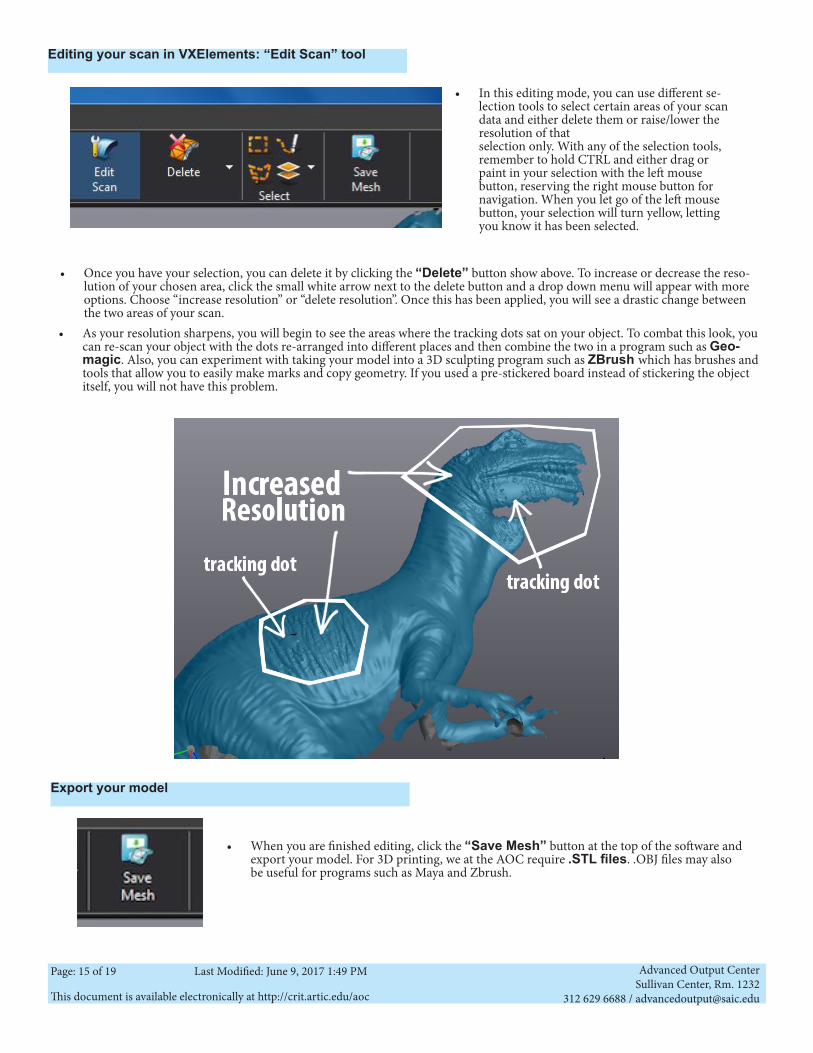
• To start off, check the box next to “Use Clipping Planes” and “De-lete Surface Outside Clipping Planes”. Next, right click in the grey box below and se-lect “Add”. There are many ways to add a clipping plane. The ones that seem to work the best are creating one from drawing a line, choosing 3 vertices, or choosing 3 tracker dots. The tracking dots method can be partic-ularly helpful if you were using pre stickered boards and want to get rid of the table or platform you scanned on. Hold CTRL and left mouse click to place your verticies or CTRL and left mouse drag to draw a line.
• After you have positioned your plane, scroll to the bottom of scan parame-ters and hit “Apply”. The software will delete all model data below that plane.
• While you are still in scan parameters, try messing around with some of the sliders. At this point, if you are not satisfied with your resolution, you can mess with your global resolution to boost the quality of the entire model. To do this, change the value in the resolution box to a smaller number. The default is 0.079. After you have done this, hit “Apply” at the bottom. Keep in mind that if you scanned at a low resolution, boosting this value up too much at this point could create holes and strange geometry. It is best to do it at the beginning. After you have achieved an acceptable global resolu-tion, feel free to experiment the scan parameter sliders such as decimation, filling holes, and sharpening operations. Hit “Ap-ply” again when you are all done.
• Before we export our model, we may want to do a bit more fine tuning. Hop into the edit scan mode by clicking the “Edit Scan” button at the top.
Editing your scan in VXElements: Clipping Planes and Scan Parameters
Advanced Output CenterSullivan Center, Rm. 1232
312 629 6688 / [email protected] document is available electronically at http://crit.artic.edu/aoc
Page: 15 of 19 Last Modified: June 9, 2017 1:49 PM
Editing your scan in VXElements: “Edit Scan” tool
• In this editing mode, you can use different se-lection tools to select certain areas of your scan data and either delete them or raise/lower the resolution of that selection only. With any of the selection tools, remember to hold CTRL and either drag or paint in your selection with the left mouse button, reserving the right mouse button for navigation. When you let go of the left mouse button, your selection will turn yellow, letting you know it has been selected.
• Once you have your selection, you can delete it by clicking the “Delete” button show above. To increase or decrease the reso-lution of your chosen area, click the small white arrow next to the delete button and a drop down menu will appear with more options. Choose “increase resolution” or “delete resolution”. Once this has been applied, you will see a drastic change between the two areas of your scan.
• When you are finished editing, click the “Save Mesh” button at the top of the software and export your model. For 3D printing, we at the AOC require .STL files. .OBJ files may also be useful for programs such as Maya and Zbrush.
Export your model
• As your resolution sharpens, you will begin to see the areas where the tracking dots sat on your object. To combat this look, you can re-scan your object with the dots re-arranged into different places and then combine the two in a program such as Geo-magic. Also, you can experiment with taking your model into a 3D sculpting program such as ZBrush which has brushes and tools that allow you to easily make marks and copy geometry. If you used a pre-stickered board instead of stickering the object itself, you will not have this problem.
Advanced Output CenterSullivan Center, Rm. 1232
312 629 6688 / [email protected] document is available electronically at http://crit.artic.edu/aoc
Page: 16 of 19 Last Modified: June 9, 2017 1:49 PM
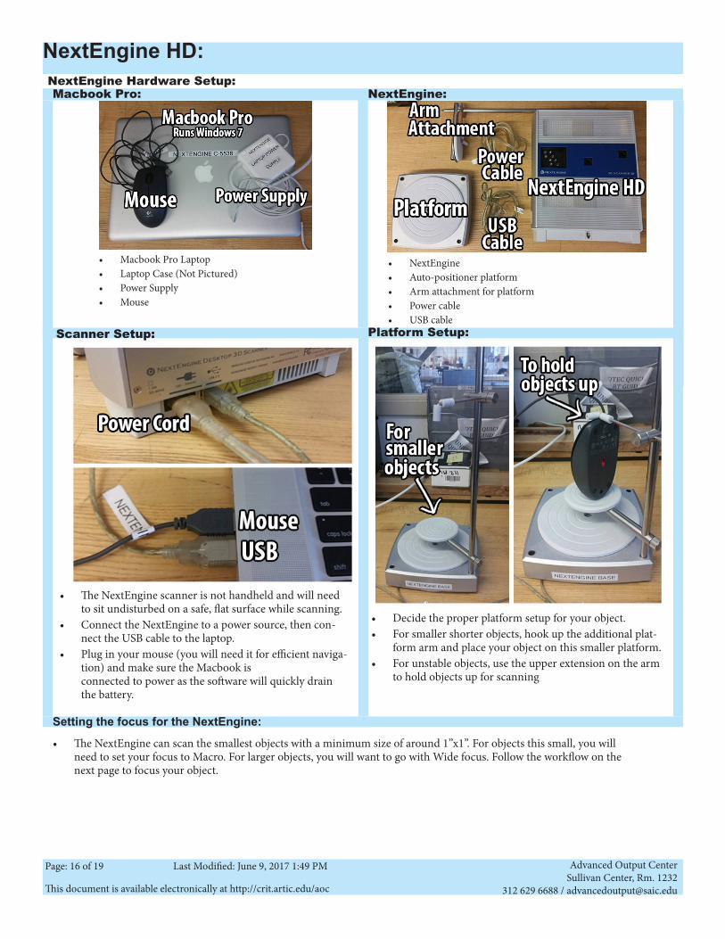
• The NextEngine scanner is not handheld and will need to sit undisturbed on a safe, flat surface while scanning.
• Connect the NextEngine to a power source, then con-nect the USB cable to the laptop.
• Plug in your mouse (you will need it for efficient naviga-tion) and make sure the Macbook is connected to power as the software will quickly drain the battery.
• NextEngine • Auto-positioner platform • Arm attachment for platform• Power cable• USB cable
• Macbook Pro Laptop• Laptop Case (Not Pictured)• Power Supply• Mouse
NextEngine Hardware Setup: NextEngine:Macbook Pro:
Scanner Setup: Platform Setup:
• Decide the proper platform setup for your object.• For smaller shorter objects, hook up the additional plat-
form arm and place your object on this smaller platform.• For unstable objects, use the upper extension on the arm
to hold objects up for scanning
• The NextEngine can scan the smallest objects with a minimum size of around 1”x1”. For objects this small, you will need to set your focus to Macro. For larger objects, you will want to go with Wide focus. Follow the workflow on the next page to focus your object.
Setting the focus for the NextEngine:
NextEngine HD:
Advanced Output CenterSullivan Center, Rm. 1232
312 629 6688 / [email protected] document is available electronically at http://crit.artic.edu/aoc
Page: 17 of 19 Last Modified: June 9, 2017 1:49 PM
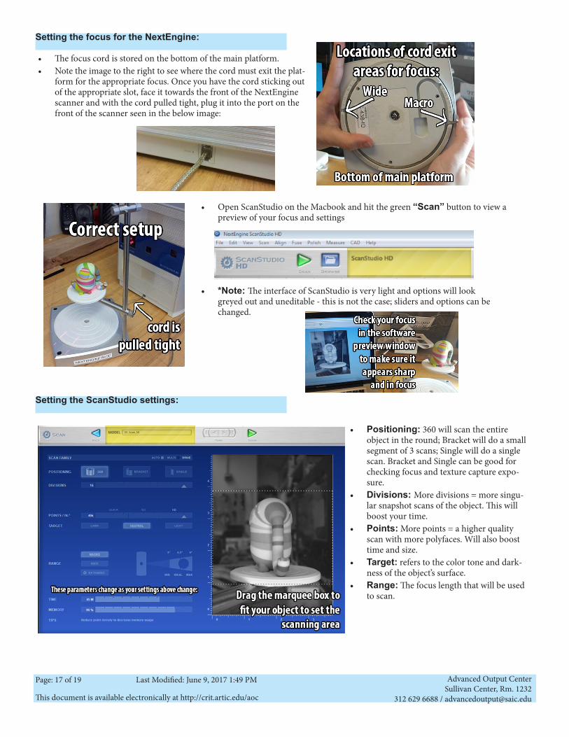
Setting the focus for the NextEngine:
• The focus cord is stored on the bottom of the main platform.• Note the image to the right to see where the cord must exit the plat-
form for the appropriate focus. Once you have the cord sticking out of the appropriate slot, face it towards the front of the NextEngine scanner and with the cord pulled tight, plug it into the port on the front of the scanner seen in the below image:
• Open ScanStudio on the Macbook and hit the green “Scan” button to view a preview of your focus and settings
• *Note: The interface of ScanStudio is very light and options will look greyed out and uneditable - this is not the case; sliders and options can be changed.
Setting the ScanStudio settings:
• Positioning: 360 will scan the entire object in the round; Bracket will do a small segment of 3 scans; Single will do a single scan. Bracket and Single can be good for checking focus and texture capture expo-sure.
• Divisions: More divisions = more singu-lar snapshot scans of the object. This will boost your time.
• Points: More points = a higher quality scan with more polyfaces. Will also boost time and size.
• Target: refers to the color tone and dark-ness of the object’s surface.
• Range: The focus length that will be used to scan.
Advanced Output CenterSullivan Center, Rm. 1232
312 629 6688 / [email protected] document is available electronically at http://crit.artic.edu/aoc
Page: 18 of 19 Last Modified: June 9, 2017 1:49 PM
Scanning with the NextEngine:
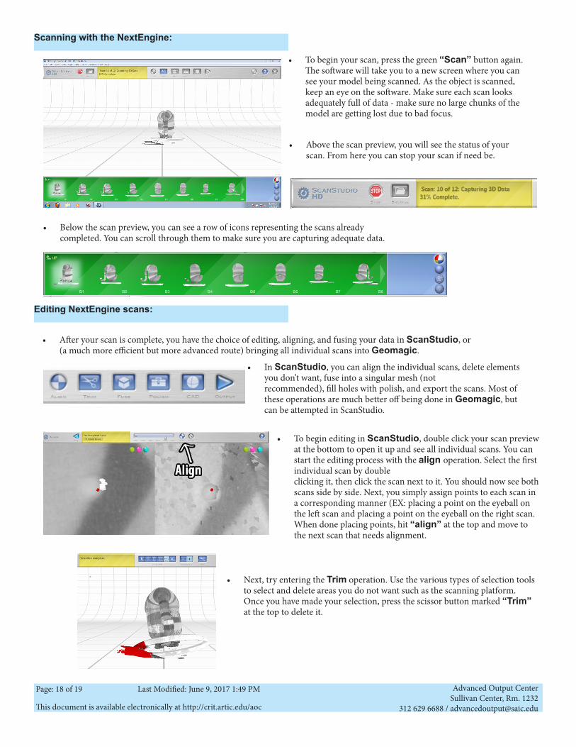
• To begin your scan, press the green “Scan” button again. The software will take you to a new screen where you can see your model being scanned. As the object is scanned, keep an eye on the software. Make sure each scan looks adequately full of data - make sure no large chunks of the model are getting lost due to bad focus.
• Above the scan preview, you will see the status of your scan. From here you can stop your scan if need be.
• Below the scan preview, you can see a row of icons representing the scans already completed. You can scroll through them to make sure you are capturing adequate data.
Editing NextEngine scans:
• After your scan is complete, you have the choice of editing, aligning, and fusing your data in ScanStudio, or (a much more efficient but more advanced route) bringing all individual scans into Geomagic.
• To begin editing in ScanStudio, double click your scan preview at the bottom to open it up and see all individual scans. You can start the editing process with the align operation. Select the first individual scan by double clicking it, then click the scan next to it. You should now see both scans side by side. Next, you simply assign points to each scan in a corresponding manner (EX: placing a point on the eyeball on the left scan and placing a point on the eyeball on the right scan. When done placing points, hit “align” at the top and move to the next scan that needs alignment.
• In ScanStudio, you can align the individual scans, delete elements you don’t want, fuse into a singular mesh (not recommended), fill holes with polish, and export the scans. Most of these operations are much better off being done in Geomagic, but can be attempted in ScanStudio.
• Next, try entering the Trim operation. Use the various types of selection tools to select and delete areas you do not want such as the scanning platform. Once you have made your selection, press the scissor button marked “Trim” at the top to delete it.
Advanced Output CenterSullivan Center, Rm. 1232
312 629 6688 / [email protected] document is available electronically at http://crit.artic.edu/aoc
Page: 19 of 19 Last Modified: June 9, 2017 1:49 PM
Editing NextEngine scans:
• Fusing your scans into one mesh is not recommended in this software as we have other programs that can complete this op-eration much more efficiently and with a much more accurate result. Geomagic, of course, is the best option - Work through the AOC’s Geomagic guide for help with this or ask the AOC Manager or Technician for assistance. If you are comfortable with Artec Studio, you can import your individual scans into Artec Studio, do the alignment in that program and do a fast, smooth, or sharp fusion to get your mesh.
• Polish operations in ScanStudio, including filling holes, is another operation best left to Geomagic or Artec Studio.
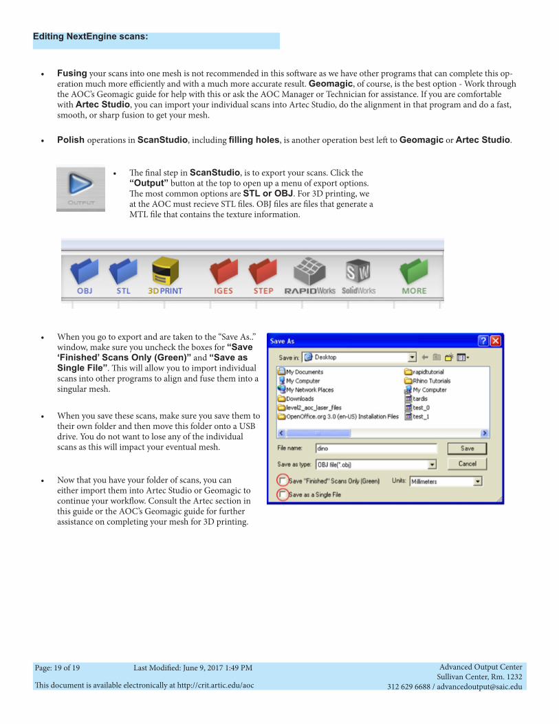
• The final step in ScanStudio, is to export your scans. Click the “Output” button at the top to open up a menu of export options. The most common options are STL or OBJ. For 3D printing, we at the AOC must recieve STL files. OBJ files are files that generate a MTL file that contains the texture information.
• When you go to export and are taken to the “Save As..” window, make sure you uncheck the boxes for “Save ‘Finished’ Scans Only (Green)” and “Save as Single File”. This will allow you to import individual scans into other programs to align and fuse them into a singular mesh.
• When you save these scans, make sure you save them to their own folder and then move this folder onto a USB drive. You do not want to lose any of the individual scans as this will impact your eventual mesh.
• Now that you have your folder of scans, you can either import them into Artec Studio or Geomagic to continue your workflow. Consult the Artec section in this guide or the AOC’s Geomagic guide for further assistance on completing your mesh for 3D printing.