Embed Size (px)
Citation preview

GUIDE FOR ARCHITECT ENGINEER FIRMS
PERFORMING SERVICES FOR THE
MARINE CORPS AIR STATION
CHERRY POINT, NORTH CAROLINA 28533-0006
REVISION 5
1 SEPTEMBER 2003


ii
RECORD OF REVISIONS REV DATE OF DESCRIPTION DATE NO. REVISION ENTERED Initial Publication 4/16/97 1 12/22/99 Review/Rewrite 2 5/1/00 **Minor Revisions** 3 10/28/01 **Minor Revisions** 4 08/29/02 **Minor Revisions** 5 09/01/03 **Minor Revisions** (paragraph 3.3.3 “Final Submittal” modified to reflect form letter information & current policies) 6 7 8 9 10 11

iii
FORWARD 1. This publication is issued to provide guidance to Architect-Engineer (A&E) firms performing services for the Officer in Charge NAVFAC Contracts, Marine Corps Air Station, Cherry Point, North Carolina. It is essential that all A&E personnel and associates responsible for preparing plans, specifications, cost estimates, studies or other services, follow all procedures and instructions outlined herein. All A&E contracts issued by OIC NAVFAC Contracts, MCAS, Cherry Point, NC reference this guide as part of the contract. 2. Contract services of this nature fall into three broad classes: a. Architect and Engineering Services related to construction, maintenance, alteration or repair of shore facilities. The product of this class of service is a set of construction documents; i.e., drawings, specifications, cost estimate and pre and post design support such as soil borings, site topography, and construction surveillance. b. Engineering Services related to planning, inspection, study and project development for existing or proposed facilities. The product of this class of service is normally a study or report. c. Environmental studies and remedial designs per Federal/State/Local environmental laws and regulations. 3. A firm providing contract services to the Marine Corps will be the Designer of Record and will incur the usual professional responsibilities and liabilities for the specific project/task. We evaluate design changes that occur during construction and actively pursue A&E liability if appropriate. The Designer of Record should become familiar with the contract terms and content of this publication with respect to pre and post construction design responsibilities. Problems typically encountered in several critical areas of project development are listed below in an effort to focus your attention. These areas should receive special emphasis as applicable. a. Field Work - Properly conducted field and condition surveys are essential. This data must be complete, accurately documented and appropriately incorporated into the plans and specifications to avoid large and expensive change orders and construction delays. b. Cost and Budget Control - Effective cost control is essential to successful project development. Establishment of an adequate budget and a design cost control system at the beginning of a project and continuing application of this system throughout the design process can prevent costly redesign of projects.

iv
c. Scheduling and Submittals - Project schedules are established at the outset to meet the customer's operational commitments and inserted in our master scheduling process to balance our workload. Adherence to the established schedule or notification of need for change is imperative. Incomplete and/or uncoordinated submittals are a major problem and will not be accepted. During fee negotiations, the Designer of Record should assure that the preparation period is adequate to allow for a thorough review by the firm prior to submission. d. Design Quality Control - Design Quality is a high priority and is the responsibility of the A&E firm. At times it appears that A&E firms rely on a Government review to provide quality control for the plans and specifications. This, of course, usually delays the return of submittals, involves additional time on our part, and often ultimately results in a poor set of bid documents. Coordination among the various disciplines as well as sections of the specifications is often a major problem that needs particular improvement. It is expected that your control program must be the primary discipline to deliver the level of design quality expectation. Time spent preparing a quality design package will reduce redesign effort and time spent resolving problems during the construction contract phase. 4. Where the provisions of this guide address the same subject as the contract clauses, the contract clauses shall govern. 5. Work of the A&E will be reviewed by OIC NAVFAC Contracts, MCAS, Cherry Point, NC only to the extent necessary to establish conformance with authorized scope and applicable Navy design criteria, and to establish reasonable assurance that work can be completed within funds authorized. The A&E shall accept full responsibility for the technical accuracy and professional quality of all work and materials that are furnished under a contract with OIC NAVFAC Contracts, MCAS, Cherry Point, NC. 6. OIC NAVFAC Contracts, MCAS, Cherry Point, NC is committed to Quality. To achieve this goal we:
a. Expect professional performance from A&Es. b. Strive for environmentally compatible solutions. c. Require A&Es to document and implement their own Quality Assurance Plan. d. Insist on attention to details e. Strive for technically sound, functional and aesthetically pleasing solutions responsive to customer needs and expectations, but also a prudent balance between need and desire, and the ideal and the realistic in terms of construction.

v
f. Require project execution to stay within scope and budget. g. Expect A&E to stay on schedule.

vi
We appreciate your support in achieving these goals and objectives. ____________________________ M. SAYGER CDR, CEC, USN
Officer in Charge, NAVFAC Contracts

vii
INDEX Page RECORD OF REVISIONS… … … … … … … … … … … … … … … … … … … … ii FORWARD… … … … … … … … … … … … … … … … … … … … … … … … … ...iii 1. DEFINITIONS AND GENERAL GUIDANCE 1.1 DEFINITIONS… … … … … … … … … … … … … … … … … … … … … … … … … 1 1.2 PHILOSOPHY… … … … … … … … … … … … … … … … … … … … … … … … … 3 1.3 CONFLICTS OF INTEREST… … … … … … … … … … … … … … … … … … … .3 1.4 RELEASE OF INFORMATION PERTAINING TO DESIGN PROJECTS… .3 1.5 ECONOMY IN DESIGN AND CONSTRUCTION… … … … … … … … ..… … 4 1.6 SELECTION OF MATERIALS… … … … … … … … … … … … … … … … … .… 4 1.7 DATA AND MATERIAL FURNISHED BY THE GOVERNMENT… … … ..5 1.8 CONSULTATION SERVICES… … … … … … … … … … … … … … … … … … ..5 1.9 A&E PERFORMANCE EVALUATION… … … … … … … … … … … … … … ..5 1.10 A&E PERFORMANCE AWARDS… … … … … … … … … … … … … … … … ...5 1.11 PROGRESS PAYMENTS… … … … … … … … … … … … … … … … … … … … ..6 Blank Naval Facilities Engineering Command Contractor's Invoice… … … … .8 Sample Naval Facilities Engineering Comm and Contractor's Invoice… … ...… 9 Blank A/E Project Accounting Form MCAS, Cherry Point… … … … … .… … 10 Sample A/E Project Accounting Form MCAS, Cherry Point… … … … … .… ..11 2. CONTRACTOR REQUIREMENTS 2.1 QUALITY OF WORK… … … … … … … … … … … … … … … … … … … .… .… 12 2.2 A&E LIABILITY… … … … … … … … … … … … … … … … … … … .… … .… ...12 2.3 SCOPE… … … … … … … … … … … … … … … … … … … … … … … … … ..… … 13

viii
2.4 CONFERENCES AND INSPECTIONS… … … … … … … … … … … … … … 13 2.5 DESIGN SCHEDULE AND PROGRESS REPORTING… … … … … … … ..14 2.6 SITE INFORMATION… … … … … … … … … … … … … … … … … … … … … 14 2.7 SURVEYS… … … … … … … … … … … … … … … … … … … … … … … … … ...14 2.8 SUBSURFACE CONDITIONS… … … … … … … … … … … … … … … … … ..14 2.9 CONSTRUCTION SCHEDULE… … … … … … … … … … … … … … … … … .15 2.10 OCCUPATIONAL SAFETY AND HEALTH STANDARDS… … ..… … … .15 2.11 CONSTRUCTION AND OPERATING PERMITS… … … … … … … … … … 15 2.12 SECURITY CLEARANCES… … … … … … … … … … … … … … … … … … ...16 2.13 CAMERA PASS… … … … … … … … … … … … … … … … … … … … … … … ..17 SAMPLE CONTRACT A&E PROGRESS REPORT… … … … … … … … … .18 3. SUBMITTAL REQUIREMENTS 3.1 INTRODUCTION… … … … … … … … … … … … … … … … … … … … … ...… .19 3.2 A&E SEAL ON DOCUMENTS… … … … … … … … … … … … … … … … … ..19 3.3 DESIGN SUBMITTALS… … … … … … … … … … … … … … … … … … … … .19 3.3.1 35% SUBMITTAL… … … … … … … … … … … … … … … … … … … … … … ...20 3.3.2 PRE-FINAL SUBMITTAL… … … … … … … … … … … … … … … … … … … ..21 3.3.3 FINAL SUBMITTAL… … … … … … … … … … … … … … … … … … … … … ..24 4. BASIS OF DESIGN 4.1 INTRODUCTION… … … … … … … … … … … … … … … … … … … … … … … 27 4.2 BASIS OF DESIGN - SUGGESTED FORMAT… … … … … … … … .… … … 27 4.3 ARCHITECTURAL… … … … … … … … … … … … … … … … … … … … .… … 27 4.4 STRUCTURAL… … … … … … … … … … … … … … … … … … … … … … … … 28

ix
4.5 CIVIL........................................................................................................... 29 4.5.1 SITE PLAN.................................................................................................. 29 4.5.2 ENVIRONMENTAL CONSTRUCTION AND OPERATING PERMITS.... 30 4.5.3 ASBESTOS, LEAD BASED PAINT, AND HAZARDOUS MATERIALS.. 30 4.5.4 WATER SUPPLY........................................................................................ 32 4.5.5 SEWERS AND SEWAGE DISPOSAL SYSTEMS...................................... 33 4.5.6 ROADS, DRIVEWAYS, PARKING AREAS, AND WALKS...................... 33 4.5.7 AIRFIELD PAVEMENT.............................................................................. 33 4.5.8 DUST AND EROSION CONTROL ............................................................ 34 4.5.9 CATHODIC PROTECTION & PROTECTIVE COATINGS........................ 34 4.5.10 FENCING .................................................................................................... 36 4.5.11 RAILROADS............................................................................................... 36 4.5.12 PHYSICAL SECURITY............................................................................... 37 4.5.13 STORM WATER MANAGEMENT PLAN ................................................. 37 4.6 MECHANICAL ........................................................................................... 37 4.6.1 MECHANICAL SYSTEMS......................................................................... 37 4.6.2 PLUMBING................................................................................................. 38 4.6.3 HEATING, VENTILATION, AND COOLING............................................ 38 4.6.4 ENERGY CONSERVATION....................................................................... 41 4.6.4.1 ENERGY CONSERVATION METHODS................................................... 41 4.6.4.2 ENERGY CONSERVATION SUBMITTAL REQUIREMENTS................. 42
FORM T-2, GUIDELINES FOR USING BUILDING DESIGN ENERGY TARGET...................................................................................................... 43
FORM E-1, ENERGY ANALYSIS.............................................................. 44

x
FORM MS-1, PROJECT SUMMARY DATA FOR MECHANICAL SYSTEMS.................................................................................................... 45
4.6.5 HEATING PLANTS AND HEATING PLANT ADDITIONS...................... 46 4.6.6 REFRIGERATION (COLD STORAGE)...................................................... 46 4.6.7 FUEL DISTRIBUTION AND STORAGE.................................................... 46 4.7 FIRE PROTECTION AND SAFETY........................................................... 47 4.7.1 FIRE PROTECTION SYSTEMS.................................................................. 47 4.7.2 SYSTEM SAFETY ...................................................................................... 48 4.8 ELECTRICAL.............................................................................................. 48 4.8.1 ELECTRICAL SYSTEMS ........................................................................... 48 4.8.2 ELECTRONIC SYSTEMS........................................................................... 50 4.8.3 INSTRUMENTATION AND CONTROL SYSTEMS.................................. 53 5. DRAWINGS/SKETCHES 5.1 ARRANGEMENT AND PRESENTATION OF DRAWINGS..................... 55 5.2 CAD DRAWING PREPARATION.............................................................. 56 5.3 DRAFTING MEDIA .................................................................................... 57 5.4 ORIENTATION........................................................................................... 57 5.5 LETTERING AND SHADING .................................................................... 57 5.6 SCALES....................................................................................................... 58 5.7 SECTION AND DETAIL DESIGNATION.................................................. 58 5.8 DRAWING NUMBERS............................................................................... 58 5.9 MATERIAL SYMBOLS ON DRAWINGS.................................................. 59 5.10 RELATION OF DRAWINGS AND SPECIFICATIONS ............................. 59 5.11 DISK LABELING........................................................................................ 59

xi
5.12 COMMON DISCREPANCIES IN NOMENCLATURE............................... 60 5.13 BORING LOG PRESENTATION................................................................ 60 FIGURE 5.2.2 TITLE BLOCK REQUIREMENTS...................................... 62 FIGURE 5.14.1 SAMPLE BORING LOG DRAWING................................ 63 6. SPECIFICATIONS 6.1 GENERAL REQUIREMENTS FOR THE PREPARATION OF PROJECT
SPECIFICATIONS....................................................................................... 64 6.2 GUIDE SPECIFICATIONS.......................................................................... 64 6.3 REFERENCES............................................................................................. 65 6.4 SPECIFYING NEW MATERIALS.............................................................. 65 6.5 PROPRIETARY AND RESTRICTIVE REQUIREMENTS......................... 66 6.6 PRE-QUALIFICATION STATEMENTS AND EXPERIENCE REQUIREMENTS....................................................................................... 66 6.7 PHRASEOLOGY......................................................................................... 67 6.8 MISUSE OF WORDS.................................................................................. 68 6.9 USE OF ABBREVIATIONS AND SYMBOLS............................................ 69 6.10 STANDARD PLATES, SKETCHES, AND DETAILS ................................ 70 6.11 SUBMITTAL PROCEDURES..................................................................... 70 6.12 BID ITEMS.................................................................................................. 75 6.13 FEDERAL AND MILITARY SPECIFICATIONS....................................... 76 6.14 INTERIM SPECIFICATION REVISIONS (ISR)......................................... 76 7. COST ESTIMATES 7.1 GENERAL ................................................................................................... 77 7.2 PROJECT DESIGN ESTIMATES................................................................ 77

xii
7.2.1 35% DESIGN............................................................................................... 77 7.2.2 PRE-FINAL DESIGN .................................................................................. 78 7.2.3 FINAL.......................................................................................................... 79 8. POST DESIGN SERVICES 8.1 CONSULTATION DURING CONSTRUCTION......................................... 80 8.1.1 GENERAL ................................................................................................... 80 8.1.2 CONSULTATION REPORTS...................................................................... 80 8.1.2.1 EVALUATION OF CONTRACTOR PROPOSED EXCEPTIONS OR
VARIATIONS TO THE CONTRACT DOCUMENTS................................. 80 8.1.2.2 EVALUATION OF CONSTRUCTION CONTRACTOR VALUE
ENGINEERING CHANGE PROPOSALS (VECPs).................................... 81 8.2 SHOP DRAWINGS/SUBMITTAL REVIEW............................................... 81 8.2.1 GOVERNMENT IS APPROVING AUTHORITY....................................... 81 8.2.2 MISCELLANEOUS SUBMITTAL REVIEW ASPECTS............................. 83 8.3 OPERATION AND MAINTENANCE SUPPORT INFORMATION (OMSI)
(OPTION)… … … … … … … … … … … … … … … … … … … … … … … … … … .84 8.4 CATHODIC PROTECTION SYSTEM INSPECTION, TESTING, AND
ACCEPTANCE (OPTION) .......................................................................... 86 ATTACHMENT A CHERRY POINT CAD STANDARDS........................................................ 88 ATTACHMENT B
CHERRY POINT MECHANICAL STANDARDS....................................... 94
ATTACHMENT C CHERRY POINT CIVIL STANDARDS… … … … … … … … … … … … … … 97

1
SECTION 1. DEFINITIONS AND GENERAL GUIDANCE 1.1 DEFINITIONS A&E: An architectural firm, an engineering firm, or an architectural and engineering firm engaged for design services. Appendix A: The document that defines th e A&E's detailed scope of work to include amount of construction funds available, activity points of contact, schedules for submittals, etc. Architect or Engineer in Charge (AIC/EIC): The individual within Cherry Point who is designated as the point of contact on technical matters. CAD: Computer Aided Drafting CMC: Commandant of the Marine Corps CNO: Chief of Naval Operations COE: Corps of Engineers CS: Contract Specialist, is the individual within the Contracts Office who is responsible to ensure that regulations, laws, and procedures are complied with in the award of a contract. Contracting Officer: The Officer in Charge NAVFAC Contracts, Marine Corps Air Station, Cherry Point, North Carolina. Only Contracting Officers are authorized to enter into, modify and/or terminate contracts, issue final decisions on contract disputes, and assign responsibility for conducting negotiations. COTR: Contracting Officer’s Technical Representative DOD: Department of Defense EFD: Engineering Field Division such as LANTNAVFACENGCOM ES: Engineering services FAR: Federal Acquisition Regulations FED: Facilities Engineering Department, Marine Corps Air Station Cherry Point, North Carolina. This department is responsible for technical review of A&E construction contract documents. In certain cases, (i.e., fire alarm systems) technical reviews are performed by LANTDIV (see next item) for the Facilities Engineering Department.

2
LANTNAVFACENGCOM: Atlantic Division, Naval Facilities Engineering Command, Norfolk, Virginia, often referred to as LANTDIV. MCON: Military Construction - Navy MILCON: Military Construction - DOD NAVFACENGCOM: Naval Facilities Engineering Command, headquartered in Alexandria, Virginia, often referred to as NAVFAC. OICC: Officer in Charge of Construction OMSI: Operation and Maintenance Support Information PEP: Parametric Estimating and Programming which is the document prepared to support a MCON project for Congress to approve the programming and appropriation cycles. The PEP is a concept design effort and replaces the 0 -35% Design/Project Engineering Documentation process. Preparation instructions are available for PEP. Project Manager (PM): The individual within the Facilities Engineering Department who serves as the Contracting Officer's primary representative assigned to a specific project. Unless specifically directed otherwise, all liaison between the A&E and Cherry Point will be conducted through the assigned PM. Variations to this standard procedure will be handled by special instructions prior to negotiation and award of the contract. ROICC: Resident Officer in Charge of Construction at a specific station or facility designated by the Contracting Officer. He/She is responsible for the field administrati on of construction contracts. All correspondence and submittals shall be addressed and mailed to: Officer in Charge NAVFAC Contracts Facilities Curtis Road MCAS PSC Box 8006 Cherry Point, North Carolina 28533 -0006 For overnight deliveries: Officer in Charge of Construction/NAVFAC Contracts Facilities Building 163 Curtis Road MCAS (ATTN: Appropriate Person or Code) Cherry Point North Carolina 28533 -0006

3
1.2 PHILOSOPHY Prior to commencing design, the A&E should become thoroughly familiar w ith current design criteria, standard method/procedures, guides, specifications, project site conditions, project costs and specific project requirements. Generally, a pre -negotiation conference will be conducted on all military construction funded projec ts and on other projects of significant magnitude or complexity where the A&E or we determine it will be beneficial. The A&E should be aware that there are differences between private work and Government work such as: (1) the Government cannot limit bid ding to a selected list of contractors known to do good work unless approved in advance under specific and limited circumstances. In most cases, any contractor may bid. Therefore, drawings and specification requirements must leave nothing to the imaginat ion. They must be clear, concise, and provide thorough detailing of existing and proposed construction. (2) Department of Defense requires the use of Federal, Military, and Industry specifications for procurement of materials and equipment covered by the se specifications. Use of these specifications assures the non -restrictive competition required in the expenditure of public funds. Proprietary specifications are not allowed without written authorization. Failure to grasp these basic differences in rul es and policies has been the source of many costly disputes. It is essential that all personnel responsible for the execution of an A&E or ES contract with OIC NAVFAC Contracts, MCAS, Cherry Point, NC study this guide and follow the procedures and instruc tions set forth herein. General instructions cannot cover every situation. Specific problems relating to a particular project will be jointly resolved in conferences with activity personnel and the PM. 1.3 CONFLICTS OF INTEREST Firms that design, prep are plans and specifications, or cost estimates for a construction contract or procurement of supplies or services, cannot provide the construction or supplies or services. This limitation also applies to subsidiaries and affiliates of a firm. 1.4 RELEASE OF INFORMATION PERTAINING TO DESIGN PROJECTS The A&E shall give no information concerning a project to anyone other than authorized station personnel, other A&Es performing design of related facilities and personnel of OIC NAVFAC Contracts, MCAS, Cherr y Point, NC. During the bidding period, any requests made of the A&E by prospective bidders for clarification or intent of drawings and specifications should be referred to the OIC NAVFAC Contracts, MCAS, Cherry Point, NC, telephone 252-466-2746. However, sources of supply for special equipment may be given to contractors. The A&E should promptly notify OIC NAVFAC Contracts, MCAS, Cherry Point, NC of any necessary corrections or clarifications of the drawings and specifications. Release in any form of i nformation pertinent to a project under design or construction for publication, for public speeches or address shall not be made without first securing clearance and a release in writing from

4
the OIC NAVFAC Contracts, MCAS, Cherry Point, NC. All material for which clearance is desired shall be submitted in duplicate. 1.5 ECONOMY IN DESIGN AND CONSTRUCTION It is Cherry Point’s objective to obtain a functionally adequate, habitable, and economical facility. In the design of all projects, it is the Navy's policy to provide functional facilities of durability consistent with the mission. The A&E shall bear in mind that the interest of the Government is to acquire facilities, which are economical in design, construction, operation and maintenance. Accordin gly, although due consideration shall be given to appearance, structures shall not entail frills and embellishments and shall not be conceived on the basis of unnecessarily complicated and costly construction systems, materials, or equipment. Although the above paragraph stresses economical design, the A&E is responsible to assure compatibility of the new structure with the architectural character of the base activity. For people oriented facilities such as Bachelor Enlisted Quarters (BEQ), Bachelor Officers' Quarters (BOQ), dining facilities, lounges, recreation areas, libraries, chapels and theaters, the A&E will be responsible for a totally integrated design. Integrated design means the complete design of a facility, taking into consideration all engineering disciplines involved plus landscape architecture and complete interior design for a comprehensively designed facility. An integrated design achieves harmony of site, landscaping, building design and functional requirements. 1.6 SELECTION OF MATERIALS Cherry Point’s objective is to provide functional and economical shore facilities for the Navy establishment. We are not in the research and development business. Consequently, it is necessary to investigate thoroughly all -new materials that have not been proven in the specific type of service involved, or whose promotion is based upon unsupported statements and lists of supposedly satisfied users. Materials must be used in a manner that will afford the maximum service at the lowest life cycle cos t. Operation and maintenance costs must be weighed against initial costs to achieve maximum economy. Before deciding upon a specific material for design or specification purposes, the following points shall be considered: a. Contemplated life of the fa cility. b. Climatic and operating conditions. c. Will material be used to the best advantage under contemplated conditions, including aesthetics? d. Is material a stock item or does it require special processing? e. Availability of material in the area of usage.

5
f. Is material proprietary or restrictive? g. Compatability with MCAS Cherry Point's Base Exterior Architectural Plan. Where new unproven materials are selected, documentation including detailed economic analysis justifying its use may b e required. 1.7 DATA AND MATERIAL FURNISHED BY THE GOVERNMENT Schematics, designs, and other criteria are furnished with the contract's Appendix A. Materials furnished by the Government such as reference drawings, surveys and soil borings are provided to assist the A&E and are not intended in any way to relieve the responsibilities of the A&E, unless otherwise noted by the Contracting Officer. The A&E of record will be totally responsible for all information described in the design documents. 1.8 CONSULTATION SERVICES During design or study preparation, various disciplines are available for consultation. Coordinate the availability of this with the PM. 1.9 A&E PERFORMANCE EVALUATION An evaluation of the performance of the A&E is prepared concurre nt with the final review of the drawings and specifications or other services performed. This evaluation includes a rating of the services performed in various categories. Such categories include thoroughness of site investigation, quality control proced ures and execution, plans/specifications accurate and coordinated, plans clear and detailed sufficiently, management and adherence to schedules, meeting cost limitations, suitability of design or study results, solution environmentally suitable, cooperativ eness and responsiveness, quality of briefings and presentations. The completed evaluation is permanently retained in the A&E's file at LANTNAVFACENGCOM for review and consideration by future Selection Boards and is distributed to the A&E of record and to other Government agencies via the Architect/Engineering Contract Administration Support System (ACASS), Portland, Oregon. A&E ratings are available for review by the Designer of Record upon request to the PM. Upon completion of the construction contract, a second evaluation is completed by the ROICC with emphasis on quality and construction of the design, timeliness and response with respect to shop drawing review, clarification of drawings/specification intent and resolution of construction problems, a nd cooperation. This rating is used in conjunction with the rating described above in determining an overall A&E rating. 1.10 A&E PERFORMANCE AWARDS
Three programs currently exist to provide recognition of outstanding performance:

6
a. The NAVFAC Design Awards Program is a biennial competition established in 1997. The purpose of the program is “to recognize excellence in design activities, design products, and associated management activities, and to publicize these accomplishments as examples to be e mulated by others.” Guidance is found in LANTNAVFACENGCOMINST 5061.7, latest edition.
b. The Industrial Incentive Plan (IIP) provides recognition for performance by a
contractor in excess of contract requirements, in one or a combination of better pro duct, speed of accomplishment, savings to the Government, and cooperation beyond the contract terms to serve the convenience of the Command, the Navy, or the U. S. Government. Guidance is found in LANTNAVFACENGCOMINST 4804.1, latest edition.
c. The NAVFAC Specifications Award Program was implemented to recognize
construction specifications of superior quality. Guidance is found in the latest edition of LANTNAVFACENGCOMINST 5061.7, and in NAVFACENGCOM letter 151 of 23 July 1996, available from Code 151 at NAVFAC Headquarters.
It is the policy of NAVFAC for all of its organizational elements to participate, as appropriate, in these programs. For further information, contact the PM. 1.11 PROGRESS PAYMENTS It is our policy to process partial payments. Generally, we process payment requests associated with a consultant’s “review submittal” (i.e., PEP, 35%, 90%, etc.) as required by the project scope. Consultants shall wait 7 days after making submittal before sending a payment request; this will allow t he COTR time to review the submittal before authorizing payment (e.g. signing the invoice). Other progress payments can also be made and will be processed when accompanied by adequate evidence of progress. Requests for payment consist of an invoice, whi ch must contain a Contractor's Invoice with original signature (NAVFAC Form 7300/41 (Rev 7/85) and a MCAS Cherry Point A/E Project Accounting Form. Submit all invoices to: Officer in Charge NAVFAC Contracts Facilities Curtis Road MCAS PSC Box 8006 Cherry Point, North Carolina 28533 -0006 Sample copies of these forms addressed above are provided in the following pages. Invoice submittals made incorrectly (i.e., invoice not signed, wrong contract number, performance statement not extended, etc.) will be promptly returned to your firm for correction. We will process all correct invoices in a timely manner. A Contractor's Release (2 copies with original signatures) must accompany your final invoice. If you have any questions concerning payment s, please contact the Contract Specialist/Project Manager.


12
SECTION 2. CONTRACTOR REQUIREMENTS 2.1 QUALITY OF WORK The A&E shall be responsible for the professionalism and technical accuracy and coordination of all services such as designs, drawings, s pecifications, cost estimates, and other work or materials furnished by the contractor under this contract. The project submitted by the A&E shall represent the best engineering solution possible for the scope of work in the A&E contract. All work must be per current criteria, guides, and specifications established by the Naval Facilities Engineering Command, and shall be per the best engineering practices. Workmanship shall be neat with all lines and lettering of uniform weight and clarity for complete legibility and satisfactory reproduction. Any computer disks submitted must be scanned for viruses using a commercial virus scanning program. All elements of submittals shall be checked by the A&E and such check shall be made by persons other than those preparing the materials and by professional personnel trained in that specific discipline. The various departments in OIC NAVFAC Contracts, MCAS, Cherry Point, NC responsible for compliance with Government requirements and standard criteria will review i t. The A&E shall correct errors and deficiencies at no additional cost to the Government. 2.2 A&E LIABILITY Neither Cherry Point's review, approval, or acceptance of, nor payment for any of the services required shall be construed to operate as a waiver of any rights or of any cause of action arising out of the performance of the contract. The A&E shall be, and remain, liable to the Government for all costs of any kind, which are incurred by the Government as a result of negligent performance of any of the services furnished. Reimbursement of costs incurred by the Government as a result of A&E's error and/or negligent performance are actively pursued by OIC NAVFAC Contracts, MCAS, Cherry Point, NC. Upon determination that there may be A&E financial r esponsibility involved, the A&E shall be contacted by the ROICC. The A&E shall be advised of the design deficiency and requested to provide a technical solution to the problem, including cost estimate. The A&E shall be further informed that it is the ROI CC's opinion that the A&E may be held financially responsible, but that the final decision rests with the Contracting Officer. A&E financial responsibility can include contractor extended overhead costs. Therefore, upon notification of potential liabilit y, the A&E should coordinate with the directing official to determine required technical support and timing to minimize delay costs. Pending final decision by the Contracting Officer, the A&E will be invited to attend all price negotiations for corrective work. The A&E shall participate as a non -voting technical advisor to the Government negotiating board. Inability to obtain agreement from the A&E as to financial responsibility or A&E unwillingness to participate in negotiations shall not be cause for delay or remedial construction contract action by the ROICC.

13
As an alternate to the above, the A&E (where design error is clearly at fault) may discharge the firm's financial responsibility through negotiation with, and direct payment to, the contractor. This action must be participated in and sanctioned by the ROICC. 2.3 SCOPE The A&E is restricted to the authorized contract scope of work provided in the contract's Appendix A. Deviations from the scope include incorporating embellishments within the project scope, increasing the cost above programmed amounts for the project, increases in area, major changes in construction criteria, the inclusion of unauthorized buildings or areas, or selections of specific systems or equipment without economic or technical evaluation. The A&E is directly responsible to the Contracting Officer and any requested deviation from the scope or elaborations within the scope must be brought to the attention of the Contracting Officer. It is the contractual responsibility of the A&E to design a facility, which can be constructed within the funds available and meets the design energy targets. Refer to Energy Conservation in the Basis of Design Section. During the progress of the work, the A&E may expect minor changes in criteria within the general scope of the project and should make necessary adjustments accordingly. Generally the PEP or 35% design submittal is intended to clarify and establish specified requirements of the project. Incorporation of Value Engineering ( VE) comments of minor consequence, systems justified on pay back which should have been evaluated during PEP or 35% design preparation, and changes in functional layout occurring during review are considered within scope of the contract. Should major changes in the scope of work be required, a contract modification will be issued. A member or individual of the A&E firm shall be designated as the Point of Contact (POC) and OIC NAVFAC Contracts, MCAS, Cherry Point, NC shall be so notified. As such, the person shall be fully cognizant of the requirements of the performance schedule. The POC will work directly with the assigned Cherry Point PM who will furnish design guidance necessary for the successful execution of the work 2.4 CONFERENCES AND INSPECTIONS Prior to submitting a fee proposal (unless exempted by the PM), it is the responsibility of the A&E to visit and inspect the location of the work and to become acquainted with all pertinent local conditions. All conferences with Station personnel (including telephone conversations, consultation, etc.) that involve some question of scope, primary design element, or other consideration of basic import, shall be submitted in writing by the A&E to the Project Manager. The general intent being that the PM will be fully apprised of all factors affecting the project. The contract scope of work or schedule of performance shall not under any circumstances be modified without a contract modification.

14
2.5 DESIGN SCHEDULE AND PROGRESS REPORTING It is the responsibility of the A&E to be fully cognizant of the contractual requirements of the schedule of performance. A report shall be provided to the PM once a month for all task orders in the contract (A&E may report separately or all on one report). Suggested format of the report is contained at the end of this section. 2.6 SITE INFORMATION Any available information relative to existing conditions at the site of the construction will be furnished to the A&E who (unless fee negotiations establish otherwise) s hall evaluate and verify such information and make field measurements and investigations as necessary to prepare adequate construction drawings and specifications. When the exposure of existing subsurface construction is considered necessary, the A&E shal l accomplish this work at his own expense after coordinating with the PM. The A&E shall contact the PM and obtain approval to dig, probe, sample or drill in order to avoid injury or damage from encountering active utilities. 2.7 SURVEYS The A&E shall m ake all field surveys required for design and preparation of construction documents. In general, this may consist of topographic site surveys, alignment, profiles and cross sections. A sufficient number of semi -permanent survey points to serve as initial horizontal and vertical survey controls for construction of the project shall be set. The horizontal control points and benchmarks shall be shown and described on the plans. The datum used shall be that used for the station or area in question and shall be shown on the appropriate site drawings. The surveying firm shall obtain from the PM the benchmark or datum location to be used for the project design. That datum shall be confirmed in writing. Failure to comply with this requirement may be cause for survey/design rework at no additional cost to the Government. Boundary surveys to be used as instruments for real estate purposes shall carry the seal of a licensed land surveyor acceptable to the political subdivision in question. 2.8 SUBSURFACE CONDITIONS The A&E is required to take soil borings and evaluate subsurface conditions in all cases where the Contracting Officer and A&E determine that soil explorations and laboratory soil test data are necessary, i.e., when adequate data is not available in Cherry Point's files. Include soil borings in project drawings. Include a note to bidders listing what subsurface information is available (i.e., test results, interpretations, recommendations, etc.) and that the information may be examined at FED. The A&E shall analyze and interpret all necessary information concerning foundation soil conditions and shall include, in the preparation of specifications and drawings, complete and specific coverage of procedures for foundation construction and for handling unusual subsurface conditions. Soil explorations and tests should conform to the essential requirements outlined in NAVFAC Design Manual DM -7, Soil Mechanics and Earth

15
Structures and MIL-HDBK 1021, Airfield Pavement. The A&E shall contact the PM prior to arriving on the station and obtain approval to dig, probe, sample or drill in order to avoid injury or damage from encountering active utilities. All project areas that require subsurface exploration (bore holes or test pits) during the design stage or will require excavation during constructions shall be scanned for the presence of existing underground utilities by the A&E design contractor (or sub -consultant). This information, in conjunction with file drawing research (review of existing as -builts from prior projects) and field survey location of above ground visible utilities, shall be used by the A&E to create a site plan showing all known utilities in the affected area. Depths to utilities shall be estimated whenever possible. All costs associated with the location of existing utilities shall be the responsibility of the A&E. For information purposes only, known utility locator sub -consultants currently doing work at Cherry Point include Pro-Mark and No-Cuts. Other firms may offer competitive services. 2.9 CONSTRUCTION SCHEDULE Construction scheduling, i.e., sequence of events and time of construction, is required to be submitted for all projects. For projects which involve interruptions of existing building operations or major utility usage, it is the A&E's responsibility to discuss the required outages and interruptions with the appropriate PM and operations personnel, and establish a construction schedule for these interruptions in the contract specifications. Where these outages and inter ruptions adversely impact the project costs or time for completion, notify the PM. A brief description of the restrictions and their basis may be required. 2.10 OCCUPATIONAL SAFETY AND HEALTH STANDARDS Occupational safety and health standards are appli cable to A&E contracts. The Department of the Army, Corps of Engineers, Safety and Health Requirements Manual, Federal, State, and local laws, rules, regulations, and special requirements established during fee negotiations shall form the basis of those r equirements. Our particular concern is directed to individual safety during performance of contract requirements while on Marine Corps property. The A&E of record (hereinafter referred to as the contractor) has the primary responsibility of assuring the safety and health of the firm's personnel while on Marine Corps property. The safety plan submitted to the Government shall be for information purposes only. The contractor shall contact the designated activity point -of-contact prior to each visit to the site. 2.11 CONSTRUCTION AND OPERATING PERMITS a. Procedures for Preparing Permit Application:

16
For projects that require construction and operating permit applications, a list of those required permits shall be included in the contract's Appendix A. The designer is responsible to have knowledge of the project's geographical location and the environmental construction and operating permits required for the facility. The designer is responsible to confirm any requirements for the project. The A&E should not be contacting the regulator without guidance and approval by the PM. The draft permit application for some permits can be submitted prior to the 35% submittal. The schedule in the Appendix A should identify the draft and final permit applica tion dates. In multi -discipline projects, like BEQ, vehicle maintenance shops, warehouse, etc. usually the regulated aspects of the design can be scheduled early in the design so that permit applications can be made. This particularly applies to civil site work, as the site work is generally complete prior to the architectural and electrical drawings. The applications will be reviewed by the PM for accuracy and completeness. If needed, the reviewed permits shall be returned for correction to the A&E alo ng with the completed review package. b. Procedures for Submitting and Obtaining Permit Approvals: (1) The A&E Firm will submit the reviewed permit applications (with corrections) by letter to the PM. (2) The PM shall be responsible for reviewing a nd certifying that permit applications are ready for signature by the applicant. The applicant's name for construction permits shall be Commanding General, MCAS Cherry Point, NC. Agent or point of contact with the regulatory agencies will be established by the Technical Code in the letter submitting the permit application. When submitting the permit applications and necessary liaison is required with the appropriate regulatory agency, CNO policy requires permit applications be signed by an 0 -6 or above. The A&E may be directed to attend any public hearings, which may be held, but only the appropriate PM shall be the official Marine Corps representative. If public notice is required by a particular Government agency (such as COE, VMRC, etc.), the PM is responsible for ensuring that advertisement is made. (3) Where possible, the intent is to have the approved permits available at the same time the 100% design is submitted for review. NOTE: Several types of permit applications require final design in formation and approved permits may not be available at the pre -final design stage. 2.12 SECURITY CLEARANCES Upon award of the A/E's contract for engineering services, the A/E shall provide the PM with a list of all personnel anticipated to need access t o MCAS Cherry Point and its tenant commands. The list shall include the individual's name, social security number, date of birth, place of birth, and place of citizenship. Any changes to the list during the

17
duration of the contract, shall be identified t o the PM at least two weeks prior to the individual's scheduled visit. 2.13 CAMERA PASS Some A/E's may find it advantageous to photograph the existing conditions at project sites for future reference to assist in their design efforts. This is usually p ermitted, but only with proper clearance. All requests to photograph facilities at Cherry Point must be made in writing to the PM at least two weeks prior to the anticipated visit.

18
SAMPLE CONTRACT A&E PROGRESS REPORT
To: Officer in Charge of NAVFAC C ontracts Facilities, Building 163 Curtis Road MCAS (ATTN: Appropriate Person or Code) PSC Box 8006 Cherry Point, North Carolina 28533 -0006 Subj: CONTRACT N62470-_____________ , PROGRESS REPORT PROJECT: _________________________________________ LOCATION: _______________________________________ CONTACTS: FAC ENG ______________ CUSTOMER __________________ 1. The following represents the design progress of this project as of (date) , 20 . 2. Project milestones for the subject project are as follows: Preliminary submittal due (date) , 20 . Prefinal submittal due (date) , 20 . Final submittal due (date) , 20 . 3. The contracted scheduled percentage complete as of the date of this report i s ___%. The actual percentage complete is ___%. 4. Our plan of action to correct the ___% slippage is as follows : (COMPLETE AS APPLICABLE) 5. The following outstanding actions/decisions should be resolved by (date) in order to maintain the cur rent schedule: (COMPLETE AS APPLICABLE) 6. Progress highlights since last report, including problems and resolutions: (COMPLETE AS APPLICABLE) 7. Projected work for next month: : (COMPLETE AS APPLICABLE) 8. Projected percent complete during next month: ___% 9. Remarks: (COMPLETE AS APPLICABLE)
I certify that this report is accurate and complete as of this date ________ , 20__ . _________________________________________ (Signature/Title)
SAMPLE

19
SECTION 3. SUBMITTAL REQUIREMENTS 3.1 INTRODUCTION This section discusses the design -related submittal of plans and specifications for review. Submittal requirements will be covered in the Appendix A. At times circumstances dictate that a formal 35% submittal be waived. When these circumstances exist, waiving the 35% submittal is intended to save the time required for submittal preparation and review and not too short-cut project development. When the formal submittal is waived, the A&E shall at the 35% design stage cont act the activity, submit the design as developed thus far, assure mutual understanding of scope and discuss functional and/or operational requirements which impact the design and/or the construction. Concurrently, the A&E shall coordinate with Cherry Poin t regarding project scope and development, i.e., guide specifications, cost estimating, fire protection, etc. 3.2 A&E SEAL ON DOCUMENTS A principal or authorized licensed/certified employee shall apply a stamp or computer generated seal to final and com plete cover sheets of plans, drawings, plats, technical reports and specifications. A stamp or computer generated seal shall also be applied to each original sheet of plans, drawings or plats, prepared by the Registered Architect or Professional Engineer or someone under their direct control and personal supervision. a. All seal imprints on final documents shall bear an original signature and date. b. Incomplete plans, documents and sketches, whether advance or preliminary copies, shall be so identif ied and need not be sealed or signed. c. All plans, drawings or plats prepared by the Registered Architect or Professional Engineer shall bear the Registered Architect or Professional Engineer's name or firm name, address, and project name. d. The seal of each Registered Architect or Professional Engineer responsible for each discipline shall be used. e. Application of the seal and signature indicates acceptance of responsibility for work shown thereon. 3.3 DESIGN SUBMITTALS Each copy of individual elements shall be separately bound and shall bear the A&E's name, the project construction contract number, and date of submittal. Do not use A&E contract number on any drawings or specifications. Incomplete submittals will NOT be accepted.

20
3.3.1 35% SUBMITTAL This submittal allows Cherry Point to review and concur with the A&E's interpretation of the functional and organizational requirements of the project. This submittal is intended to clarify and establish specific requirements for the project. Elements will include: For projects in AutoCAD, Versions 2000/2002 shall be used and all computer aided drafting (CAD) compact discs (CDs) (with individual CAD drawing files BOUND prior to writing to CD) shall be forwarded to the PM at the 35% submittal .
(1) Drawings with a minimum of the following:
(a) Civil site and utility plan.
(b) Architectural floor plans, including room names and dimensions; furniture footprint plan reflecting and including an updated collateral equipment list coordinated with the activity; finish schedule, roof plan, elevations, and typical wall section.
(c) Structural to include foundation plan, floor framing and roof framing plan.
(d) Mechanical site plan, plumbing floor plan showing fixtures and equipment location, HVAC floor plan showi ng equipment locations, one or two line duct layout, preliminary piping runs, mechanical room plans showing major equipment and maintenance access space and legends.
(e) Electrical site plan, lighting floor plan and fixture schedule, power floor plan, specia l systems (telecommunications, FA, CATV, CCTV, intercom, etc.) floor plan(s), one-line diagrams and/or power riser diagrams and legends. NOTE: Electrical floor plans should indicate proposed number and location of fixtures, outlets, devices, etc., but should not indicate any conduit or cable runs. Electrical floor plans should also indicate proposed location and space required for electrical equipment such as transformers, switchboards, panel boards, telecommunication equipment, etc. (2) Basis of Design - See Section 4. (3) Preliminary Color Design - See Section 4.3. (4) Outline Specification - See Section 6. (5) Cost Estimate - See Section 7. For bid items, if estimated construction cost exceeds the established budget, identify potential additive bid items per Section 6.12.

21
(6) Geo-technical reports and foundation studies. (7) Proposed construction schedule and schedule of major utility outages. See Section 2.9. (8) Calculations - Include to the extent required by the Basis of Desi gn. See Section 4. (9) Energy Conservation Documents (Analyses). See Section 4.6.4. (10) Dust and Erosion Control Plan. See Section 4.5.8. (11) Storm water Management Plan. See Section 4.5.13. NOTE: The basis of design and outline specifica tion should be combined into a single bound document. Other elements must be separate. Distribution and number of copies is Activity/project specific and will be provided by the PM in the contract's Appendix A. 3.3.2 PRE-FINAL SUBMITTAL A technical r eview is required to ensure compliance with Navy, DOD and Non -DOD requirements, construction adequacy, and a functional check. The A&E should submit plans and specifications in final form from his viewpoint, thus preventing time -consuming reviews of incom plete plans and specifications. Each 35% or previous review comment sent to the A&E shall be returned with each comment addressed. If the comment was incorporated into the design, a response shall so indicate. If the comment was not incorporated, an e xplanation shall be provided for not doing so. Elements: (1) Plans - coordinated, checked, and complete from the A&E viewpoint (except for NAVFAC drawing numbers). (2) Mechanical Drawings - Area for tube, coil, filter, etc., removal must be shown dotted and labeled. Piping and equipment isometrics should be included for all but the simplest systems. If space is limited, show dotted in major equipment from other trades; air compressor, domestic hot water heater, electrical panels, etc. Consider use of 3-D isometric layout for spaces that are crowded. Prior to final submittal an overlay should be made of plumbing, mechanical, electrical and communication equipment in the space to verify required clearances and access space. The sequence of operation, control diagrams, and point schedules for the temperature control system should be shown on the drawings.

22
(3) Color Design (if applicable): (a) Finish schedule with color code columns completed with the appropriate color codes. (b) Where other than usual painting or wall covering schemes or ceramic wall tile, graphics, built -in equipment or window treatments are used, labeled floor plans, elevations and sketches using the color codes as necessary should be drawn. (c) A color legend along with color notes should be completed referencing and specifying all finishes used in the finish schedule. (d) A color board identifying all finish colors listed in the finish schedule, labeled with appropriate color codes. The board should be a reasonable, transferable size (maximum size 20" X 30"). (e) Check with activity to ensure that collateral equipment list is accurate. If necessary, revise the collateral equipment list and furniture footprint. (4) Specification - photographic copies of fully edited guide specifications supplemented as required are acceptable. Specifications must be thoroughly edited for coordination with the drawings. See Section 6. (5) Cost Estimate - See Section 7. (a) Computerized Estimate (MEANS, MCASES, etc): 1. Computer run estimate 2. Marked 35% estimate 3. Vendor/manufacturer quotes (b) Manual Estimates: 1. Backup estimate with summary sheets 2. Marked 35% estimate 3. Vendor/manufacturer quotes (c) Bid Items - if estimated construction cost exceeds construction funds available, identify in conjunction with the activity additive bid items and respective values with detailed back -up estimates required to produce a base bid within available construction funds. See Section 6.13 for additional information.
23
(6) Draft Environmental Construction and/or Operating Permit(s). (7) Calculations - engineering calculations shall be neat, legible, logically ordered, bound and indexed. Design data shall be clearly stated. Formulas and reference sources shall be cited. Designers and checkers shall initial and date each computation sheet. Upon request A&E firms using computerized design procedures must submit, in conjunction with calculations: (a) A description of the type(s) and configuration(s) used. (b) Copies of all pertinent input and output data. (c) Documentation of each program may be requested, including a written summary of the program intent and function, assumptions, formulas, numerical metho ds used, nomenclature, limitations of the program, and references used in developing the program. In the event "non -proven" programs are used, a computer run by the A&E, for check problems may be required (by the reviewer) for verification, which will be at no expense to the Government. (d) See Submittal Flow process in Energy Conservation (Section 4.6.4.). (8) Dust and Erosion Control Plan (See Section 4.5.8). (9) Storm water Management Plan (See Section 4.5.13). (10) Manufacturer's catalog data of major equipment that was used as basis of design. Data shall include dimensions, weights, and specified ratings. Examples of major equipment requiring catalog data are: (a) Switchgear/substations (b) M-G sets (c) Eng-Gen sets (d) IDS (e) Frequency converters (f) Filters (g) Heat rejection equipment (h) HVAC

24
(i) Pumps, fans and air compressors (j) Domestic hot water heaters (k) Other special equipment (11) All marked materials returned to the A&E with p revious submittal (i.e., plans, specifications, cost estimate, Basis of Design, Calculations, reports, etc.). Distribution of plans, specifications and cost estimates are project specific and are provided by the PM in the contract's Appendix A. 3.3.3 FINAL (100%) SIGNED SUBMITTAL
a. The purpose of the final submittal is to finalize design phase and prepare
documents for construction contract advertisement. Each pre-final comment sent to the A&E shall be returned with each comment addressed. If the co mment was incorporated into the design, a response shall so indicate. If the comment was not incorporated, an explanation shall be provided for not doing so.
b. Elements include appropriate signatures and final tracings. All documents shall have the seal of the A&E responsible for the work as required by Section 3.2. A firm or partnership stamp is not acceptable. Where the firm's state of residency does not provide for professional sealing, compliance with the state's normal requirements will suffic e. c. Final tracings, masters and any other data developed by the A&E shall become the property of the Government unless stated otherwise in the contract. d. Drawings on CD-R in individual AutoCAD .DWG files PLUS one hard copy of 1/2 size and one hard copy of full-size drawings. On a project specific basis, PM may have the A&E provide .PDF files in addition to .DWG files. Individual CAD drawing files will be BOUND prior to writing to CD. Prior to submission, scan all computer disks for viruses using a commercial anti -virus scanning program. All discs shall be labeled as described in paragraph 5.11. e. Final Spec on CD-R in SPECSINTACT format. f. Included on this CD with Spec will be the Cost Estimate, Calculations, Field Notes, Reports & Studies, Environmental Construction and/or Operating Permit(s), if applicable, Spec Title Page signed by the A/E , and any reports or attachments that need to be included in the contract, ALL in individual .PDF files . CD shall be left open by the A/E so that information can be added to or corrected, if necessary. Cost estimates in Adobe Acrobat .PDF format on SPECS CD-R include:

25
(1) Computerized estimate, which includes a computer run estimate, marked pre -final estimate, and vendor/manufacturer quotes (i. e. MEANS, MCASES, etc). (2) Manual estimates (if applicable) that include a backup estimate with summary sheet(s), marked pre -final estimate, and vendor/manufacturer quotes. (3) Proposed bid items with detailed backup estimate (if estimated construct ion cost exceeds construction funds available). NOTE: All computations, studies, and significant material shall be produced in bound book form in Adobe Acrobat .PDF format on SPECS CD. g. Interior Color Design (if applicable), which may include: (1) One color board (maximum size 23” X 30”) displaying all materials labeled with color codes. (2) Two (2) 8-1/2" X 11" binders containing all coded materials. (3) Furniture footprint reflecting final collateral equipment list and the color study when one has been required. (4) Finalized finish schedule, color legend and color notes. h. All marked materials returned with previous submittal. i. A/E Quality Control Check prints. j. Special Scheduling Paragraphs.

26
k. Your firm will be expe cted to perform a quality control review. This review will evaluate both the technical accuracy and discipline coordination. Your Final Submittal shall include a single set of final prints and specifications highlighted to indicate the review was performed. In addition it will indicate that corrections were made and a signature in the Quality Review Signature Block (see below) on the original in the Quality Control line of the title block on the cover sheet of D size drawings, indicating a quality review was performed. Such items as section, detail, and note references to other sheets, major dimensions, and equipment locations shall be marked. Verify that all equipment is correctly identified the same way on all sheets and in the specifications. Ensure that all work as indicated on the drawings is fully and consistently specified.
QUALITY CONTROL REVIEW _______________________ ___________ Signature Date
Quality Review Signature Block Distribution is as specified in the contract's Appendix A.
27
SECTION 4. BASIS OF DESIGN 4.1 INTRODUCTION The basis of design should be a bound presentation of facts sufficiently complete per the following suggested format to expedite Cherry Point's review of the preliminary submittal. Detailed design computations, sizing of members or conductors, details of connections, etc., are not necessary with the basis of design, but general computations supporting system selection are required. The Criteria Manual is MIL-HDBK-1190 (latest edition), Facility Planning and Design Guide. 4.2 BASIS OF DESIGN - SUGGESTED FORMAT The following guidance is written around new building type construction. Where a project consists primarily of mechanical, electrical, structu ral, or another discipline, the basis of design shall provide more detailed information for the major discipline. 4.3 ARCHITECTURAL a. Statement of the type of construction adopted with reference to the occupancy, anticipated tenure of usage, degree of fire resistance, and maximum allowable floor areas and number of stories allowed by the Uniform Building Code. b. Statement as to the type of thermal insulation to be provided, when required, and the value of the U factors for the various portions of the structure, i.e., roof, walls, floor, etc. Also provide description of all architectural energy conserving features to be incorporated, including any passive solar systems. Refer to the Energy Conservation Section for additional information. Refer to AS HRAE Standard 90.1 - 1989, Section 8.5 (latest edition) for determining U factors instead of previous DOD criteria. c. Provide a one page narrative description of the preliminary color design concept addressing Architectural finishes and colors. Describ e materials for all major items of construction and all interior and exterior finishes. The description of finishes (colors, textures, and patterns) shall be accomplished by the use of a finish schedule, color legend and notes. The finish schedule on the drawings shall identify interior building material finishes (A&E may choose room -by-room name or number format). For the completed project all reference to building colors shall be on the drawings in the color legend that is referenced to the finish sche dule. Any finishes not referenced in the color code columns of the finish schedule should be in either the comment section or color notes. Provide a generic color board referencing the narrative. d. A description of items not considered to be a permane nt part of the structure, such as workbenches, shelving, bins and removable partitions.

28
e. Analyze the design for compliance with latest edition of DM -01.03, Architectural Acoustics, and DM3.10, Noise and Vibration Control. Include a statement as to gen eral adherence to the criteria. When required, list areas of high noise and vibration and acoustic design principles applied. f. Facilities required to be accessible to physically handicapped persons shall be designed and constructed or retrofitted per the Uniform Federal Accessibility Standards (UFAS), Federal Register, (49 FR 31528 latest edition) (reference (5e)). Requirements for new construction, additions, and alterations vary and are specified in the standards. In general, all facilities worldwi de which are open to the public, or to limited segments of the public, or which may be visited by the public in the conduct of normal business, shall be designed and constructed to be accessible to physically handicapped persons. This includes facilities constructed with non-appropriated funds, privately financed facilities on military installations, and contractor -owned facilities where the Department of Defense is funding all or any part of the construction. In fact, every facility should be designed to assure access to physically handicapped persons unless its intended use is specifically restricted to able -bodied military personnel. Able -bodied military personnel are defined as those military personnel considered to be physically fit for duty. At lea st five percent of family housing units at an installation and not less than one unit shall be accessible. g. Computation of gross floor area should be done per MIL-HDBK-1190 (latest edition), and should be indicated on the drawings. h. Analysis of Lif e Safety Code (NFPA 101) requirements for all occupancies involved. Determine occupancy classifications, calculated occupant load, number and size of exits and other requirements. Describe unusual or critical code requirements and indicate how such requi rements will be met. i. Describe special construction features incorporated into the facility such as barred windows, special wall/roof construction, raised computer flooring, RF Shielding, HEMP protection, etc. j. The architect shall identify to the s tructural designer all partitions, i.e., non -load bearing walls (full height and less than full height), so that required strengthening can be determined. These considerations shall include seismic, wind and other dynamic loads applied to these walls. Th e partitions may be wood or steel stud framed, or CMU. Appropriate control joints shall also be considered. 4.4 STRUCTURAL a. Description of foundation conditions, type of foundation to be used, method by which the allowable bearing values is to be det ermined, and maximum allowable bearing capacity for the foundations. Geo-technical information including field boring notes and report of recommendations shall be submitted.

29
b. Statement of the type of construction adopted, and reason therefor, with capacity, dimensions, or other size criteria, and list of material selected with design strengths. c. Special features to be included in the structure, which are not evident from the drawings. d. Description of the structural floor and roof systems proposed, with length, spacing and size of principal members (for beam and girder, etc.). e. Description of the Lateral Force Resisting System proposed with appropriate materials and dimensions. f. Statement of live loading to be used, to include floor loads , wind, snow, earthquake, etc., with data to justify. g. Statement of any special considerations that affect the design (e.g., super flat floors for high stacking warehouses, special corrosion resistance requirements, retractable roofs, etc.). h. Contact the cognizant PM for extent of crane design required. Include special considerations as to crane and monorail requirements; i.e., special architectural -structural considerations, area of service, and type of system. i. The usual accepted means of str uctural system selection is economy. Demonstrate this with computations of various appropriate framing systems and cost comparisons of each, including: (1) Typical bay member sizing and cost comparisons of alternate structural systems; (2) Horizontal force resisting system for wind and earthquake; (3) Consideration of unusual geometry (long span, high bay, deep cuts, etc.); (4) Consideration of heavy equipment supports. 4.5 CIVIL 4.5.1 SITE PLAN a. Provide site plan showing layout and utili ty connections. It is Cherry Point's policy that site plans shall be drawn to a scale of 1" = 25' whenever feasible, allowing for ease of conversion to the metric system and aid in the eventual compilation and updating of utility and planning maps.

30
b. Describe and quantify the dredging requirement, proposed disposal plan, status of the dredging permit, and status of the Environmental Impact Statement (EIS). Identify dredge depth and quality control procedure requirements. 4.5.2 ENVIRONMENTAL CONSTRUCTION AND OPERATING PERMITS a. Identify with a narrative description the pollution that will be generated on -site during construction and a proposed method that can be specified to control the pollution. A detailed description of construction pollution con trol shall be outlined in the basis of design for air pollution, pollution to ground and surface waters and the central prohibited discharges to on-site sewage systems. Provide as appropriate the elements proposed for final design needed for a Storm Water Pollution Prevention Plan. b. Environmental Operating Permits - Identify by a narrative description each of the permits needed to operate the proposed design. Identify assumptions and limitations that are proposed as a basis for design. Address discha rge limitations of air and water pollution with regard to MIL-HDBKs and regulatory requirements. The above requirement is particularly related to designs for incinerators, sewage plants, water plants, industrial process facilities, power and heat generato r facilities, and solid waste handling facilities. c. Design of Oil Spill Prevention Control and Countermeasures (SPCC) systems shall be per Federal Register, Title 40, Part 112 titled Oil Pollution Prevention. The Civil Engineering Branch will provide detailed criteria for incorporation of SPCC design into basis of design. 4.5.3 ASBESTOS, LEAD BASED PAINT, AND HAZARDOUS MATERIALS a. The A&E shall investigate for the presence of asbestos, lead or hazardous materials that will be disturbed in any way b y the proposed work. This investigation shall be preformed by a North Carolina Accredited Asbestos Inspector and shall identify any suspected material that appears to be involved in the proposed work. The A&E shall determine the scope of the investigatio n, using information in the guide specifications NFGS-13281 and 13283 as guidance, and enlisting the advice of consultants. The project architect should develop scope for miscellaneous building materials, the mechanical engineer for HVAC and process systems, and the electrical engineer for power manholes and other wiring systems. It is important to realize that debris from one discipline's work can adversely effect the work of others. A certified testing laboratory shall be used to sample and test the suspected asbestos, lead based paint or hazardous materials. However, the Asbestos Inspector and the A&E shall review the work of the laboratory and require additional tests that may be required to fully determine the extent of the asbestos, lead based paint or hazardous materials. Change orders for additional testing are appropriate. Provide a signed report certifying the investigation. The report shall be certified by the Asbestos Inspector and shall include the Inspector's certification number. Distribution and number of copies of this report will be provided by the PM in the A&E's contract Appendix A. If asbestos, lead based paint or hazardous materials are

31
found, the A&E shall indicate the extent of asbestos, lead based paint or hazardous material removal in the project documents and specify removal procedures per applicable regulations and in sufficient detail for the contractor to submit an accurate bid. (Note - Pipe insulation shall be indicated by major systems on as -built type drawings, etc.). If testing is performed and the material does not contain asbestos or lead based paint, add a note on the drawings to the effect.
b. For asbestos removal, several different cleanup scenarios are presented:
(1) Complete Cleanup: A project is scoped for removal of all asbestos bearing materials within a crawl space. In this case, the A&E shall be requested to take asbestos insulation samples (pipe coverings), soil surface contamination samples (debris), and soil contamination samples. The results from testing the soil and soil surface contamination samples will be used to determine the scope of cleanup operations. One alternative to consider when soil contamination occurs would be to determine if the debris trail follows a geometric pattern; i.e., onl y under the pipe runs. If this is true, it might be more economical to treat those areas, only, by removal. However, the requirement for soil removal should be backed by laboratory tests and proper interpretation of the law as it pertains. If soil surfa ce contamination exists, removal of the debris, only, may be adequate if subsequent air and soil samples indicate an acceptable environment. If contamination is not found, the following statement shall be placed on the drawings beside the crawl space: "Soil (debris) has been tested and found to be asbestos free." When soil samples show contamination, the statement, "Soil (debris) is contaminated with asbestos" shall be used. Similar situations occur in other areas of a building, such as mechanical rooms , attics and high truss areas, and spaces between floors. In attics, the ceiling and/or the insulation above it would be treated like the soil previously mentioned. The appropriate statement would then have the format: "The ____________ area is contaminated with asbestos (debris)." (2) Partial Cleanup: A project where insulation has been tested as required and some asbestos has been found, and only the pipes/materials being worked on will be reinsulated or removed and replaced. This could happen in a crawl space, attic, mechanical equipment room, high truss area above ceilings, pipe chases and other areas. In these cases, the following note shall be placed on the plumbing or mechanical drawings, as well as drawings of other disciplines, which will be performing work in area: "Asbestos is present in the ______________ area. Protect all personnel within this asbestos area during the entire construction period by complying with 29 CFR 1926.58." Also when appropriate, along with the 35% submittal, addr ess a letter to the Station with the following comments: "Asbestos laden pipe insulation was found during sampling on the following lines and it is likely that asbestos insulation exists beyond the limits of this project." Then list the pipelines involve d. A similar scenario would be appropriate for new electrical work in existing manholes. Cables that are not to be worked on need not be cleaned. However, the contractor must be warned about the potentially hazardous environment.

32
(3) No Cleanup: A project where the building is older than 1975 and no work is to be done on existing piping or asbestos suspected materials (i.e., apparently no testing required). However, the A&E should consider that, when running new piping or conduit in an older building , the existing finish materials that require drilling and cutting to allow the work to pass, or the spaces, especially attics and crawl spaces, through which the work must pass may be asbestos contaminated. Testing should be done and the existing asbestos identified. In this scenario, the same note shall be applied to the drawings as if it was a Partial Cleanup: "Asbestos is present in the _______________ area. Protect all personnel within this asbestos area by complying with 29 CFR 1926.58." (4) Total Demolition: A project where a building or facility is to be demolished and the site readied to receive a new building or facility. Each possible building material that historically could have been an asbestos based material should be tested. Instances of asbestos contamination should be clearly indicated, by specific building system, with special care taken to include any secondary contamination that might have occurred due to debris from that system. If a specific system indicates a tendency toward a sbestos contamination, then the entire system should be so treated. Also, in facilities scheduled for demolition, investigation should be made to find sources of hidden asbestos. c. If the A&E decides to obtain the services of an outside testing organiz ation to assist in defining the asbestos related work, the emphasis should be on an organization that can provide in-house engineering. They should be capable of using engineering judgment and experience to search out suspected sources of asbestos, with the initiative to suggest further testing when required, and the knowledge and experience with the EPA directives to interpret them and suggest the most financially efficient cleanup methods. They should also be capable of producing detailed engineering dr awings delineating the extent of the asbestos removal effort required, in a biddable format, and professionally seal these drawings themselves. 4.5.4 WATER SUPPLY a. Describe the existing system, indicating particularly the type, capacity, condition, present water use, and unsatisfactory elements. b. State type of construction proposed, materials for water mains, type of well, etc. c. For exterior distribution systems, state design parameters including domestic and fire flow, residual pressure, eleva tion differentials, etc. Include designer's initial estimate of pipe sizes. For projects geographically located within the Continental United States coordination with the appropriate State Regulatory Agency is required.
d. State tentative sizes, elevations, capacity, etc., as can readily be determined without long computations or design consideration for reservoirs, treatment units, pumping stations, well pumps, and such units.

33
4.5.5 SEWERS AND SEWAGE DISPOSAL SYSTEMS a. Describe the existing system ind icating particularly the type, capacity, condition, present flow, and unsatisfactory elements. Address the adequacy of the down stream sewers for capacity and of the pumping station to prevent overflows including alarms, power, and assumed response time by the base operations staff. b. Describe the degree of treatment and each of the unit processes proposed. Address the operational requirement related to the selected type of treatment. c. State design factors with present and projected design populati on loads for sewage treatment plants. For projects geographically located within the Continental United States, coordinate with the PM for special meetings and submissions to the State Regulatory Agencies. d. State materials to be used for sewer systems and sewage treatment plants. e. Identify standards (Federal, State, local) governing the design. f. Describe the impact of steam condensation and cooling water discharges on existing sewer piping and sewage treatment plants and the estimated cost of d istribution and treatment of this additional loading. Analyze the discharge alternatives for industrial wastewater related to a direct discharge, no discharge or a discharge to the sanitary. Provide a cost based solution considering applicable environmen tal regulations. 4.5.6 ROADS, DRIVEWAYS, PARKING AREAS, AND WALKS a. State general soil conditions, with a brief outline of soil exploration and testing performed.
b. Describe the type and volume of traffic, controlling wheel loads and types or classes of roads under consideration with justification for any deviation from criteria thicknesses for these classes.
c. Evaluate existing pavement conditions for reuse. Indicate residual structural valves for each differing pavement. d. Note condition of adjacent drainage features. 4.5.7 AIRFIELD PAVEMENT a. The relative economies of rigid and flexible paving are constantly changing with the improvement of design features and construction techniques and with the development of new products. These factors are of significant importance in both new pavement construction and in the rehabilitation of existing pavements. All projects require careful study and evaluation of the in -place materials and the proposed

34
construction materials. For these reasons, Cherry Poi nt will review carefully the proposed design cross sections on all major airfield paving projects. b. State general soil conditions with a brief outline of soil exploration and testing performed. c. Identify design wheel loading, type of aircraft, any abnormal operating conditions. d. Identify type of pavement; bituminous, concrete, reinforced, etc. e. Note deviations from Naval Air Systems Command planning standards with reasons therefor. f. Describe method of handling storm drainage. g. State type of lighting to be provided. Evaluate adequacy of existing runway and taxiway regulator capacities. 4.5.8 DUST AND EROSION CONTROL a. Dust and erosion control, where deemed necessary, will be considered an integral part of all design and construct ion projects. Such controls will be generally limited to areas actually scarred or denuded in the process of constructing a project. Dust and erosion control will not be confused with landscaping. The 35% submittal will contain the necessary design data , outline specifications, and costs for dust and erosion control measures where applicable. The Basis of Design will include a statement regarding the type of treatment selected, affecting areas, and reasons for selection of type and determination of area s. b. Erosion Control Plan for projects in North Carolina - An Erosion Control Plan (ECP) must be filed with the Department of Environmental Management (DEM), Land Quality Section, Wilmington or Washington, North Carolina for projects, which disturb more than one acre of land. The ECP should be filed with the State at the Pre -final design stage. The A&E shall forward the ECP application along with the appropriate application fee to the PM for final review, signature and submission to the State. Permit fees shall be included in the A&E's contract Appendix A. The A&E of record is responsible for coordinating with DEM and obtaining written approval for the ECP. 4.5.9 CATHODIC PROTECTION & PROTECTIVE COATINGS Cathodic Protection (CP) is required for all underground or submerged structures on which corrosion may have severe environmental or structural effects or significant economic impact. a. Types of structures for which the installation of CP and protective coatings is required by Federal Regulations include, but may not be limited to:

35
(1) Underground Fuel Storage Tanks (40 CFR 280 and 281) (2) Fuel and POL Pipelines (49 CFR 195) (3) Natural Gas Pipelines (49 CFR 192) (4) Liquefied Natural Gas Facilities (49 CFR 193) b. In addition to the structures above, CP and protective coatings must be provided per NAVFACENGCOM policy for the following types of buried/submerged metallic structures regardless of soil or water corrosiveness: (1) Underground oxygen piping (2) The waterside of new steel sheet-pile bulkheads (3) New steel pile pier supports and steel fender piles (4) Steel water storage tanks (elevated or reservoirs) (5) Underground structures storing hazardous products (6) Steel utility piping in soils having resistance b elow 100,000 ohm-cm (7) The exterior bottom of aboveground POL tanks (8) Hydraulic piston cylinders for elevators and lifts (standard CP design) c. The requirement for CP, protective coatings and joint bonding on the following types of structures must be determined by economic analysis and the recommendations of a qualified corrosion engineer based on soil resistance or corrosiveness if submerged: (1) Ferrous metal gravity sewer lines (any soil resistance) (2) Existing steel waterfront structures (3) Buried ductile/cast iron pipe (soil resistance above 10,000 ohm -cm: joint bonds only) (4) Concrete encased rebar in piles for piers, seawalls and quay walls. (5) Steel sheet-piles (landslide) (6) Underground compressed gas distribution systems (except oxygen) (7) Water distribution systems

36
(8) Concentric neutral cable (9) Heating (steam) distribution systems – Cherry Point uses primarily an Impressed Current System. (10) Other buried/submerged metallic structures not covered above d. CP surveys and designs must be performed by a registered corrosion engineer or National Association of Corrosion Engineers (NACE) certified corrosion or CP specialist with at least five years experience in the type of CP system being designed. The consultant's qualifications shall be verified. e. Designs for CP must comply with the following: (1) MIL-HDBK 1004/10, Electrical Engineering, Cathodic Protection (2) CP systems must be designed to provide protective potentials that meet the requirements of applicable NACE recommended practices (i.e., RP01 -69, RP02-85, RP03-88, etc.) (3) All CP designs must be based on specific field tests made at the proposed construction site. Tests would include soil resistance (Wenner Four Pin method), w ater corrosiveness (pH), structure-to-electrolyte (S/E), and potential measurements (on existing structures or test specimens). Results of field -testing will be provided with design submission. (4) Designs must include test stations, electrolyte access points and/or reference electrodes required for routine operation, maintenance and potential surveying of the CP systems. (5) Specifications will provide procedures for recommended acceptance testing including static (native) potentials, initial and fi nal system potentials, and interference tests. (6) Air Force designs will also comply with the current Air Force CP Engineering Technical Letter (ETL). 4.5.10 FENCING. State type, height, and justification for fencing. 4.5.11 RAILROADS a. State general soil conditions, outline the soil exploration and testing performed or to be performed, and such results thereof as may be available.

37
b. State type of service for which railroad track will be provided, anticipated volume and type of traffic, the rul ing grade, and the maximum curvature. c. Describe proposed type, source and thickness of ballast, weight of rail and source, treatment, and dimensions of ties proposed. 4.5.12 PHYSICAL SECURITY a. State the type of classified material to be stored and describe the specific construction standards required by OPNAVINST 5510.1_ (latest edition), Department of the Navy Information and Personnel Security Program Regulation. b. State the category of Arms, Ammunition and Explosives (A&E) to be stored and describe the level of protection required by OPNAVINST 5530.13_ (latest edition), Physical Security Instruction for Sensitive Conventional A&E. c. Based on consultation with the activity's Security Officer and OPNAVINST 5530.14_ (latest edition), Navy Phys ical Security and Loss Prevention Manual, state what areas will be designated as restricted areas. Describe the provisions incorporated in the design to ensure the proper level of control in these areas. 4.5.13 STORM WATER MANAGEMENT PLAN State what management plans are required. For projects in North Carolina, a Storm Water Management Plan (SMP) must be filed with the Department of Environmental Management (DEM), Water Quality Section, Wilmington or Washington, North Carolina for projects that disturb more than one acre of land. An outline of the proposed SMP will be included in the 35% submittal and should be filed with the State at the Pre -final design stage. The A&E shall forward the SMP application along with the appropriate application fee to the PM for final review, signature and submission to the State. Permit fees shall be included in the A&E's contract Appendix A. The A&E of record is responsible for coordinating with DEM and obtaining written approval for the SMP. 4.6 MECHANICAL 4.6.1 MECHANICAL SYSTEMS As an objective, mechanical systems should be simple and reliable while providing a comfortable environment for building occupants with minimum consumption of energy. The Navy does not have building operators, the mechanical systems sh ould be self-sufficient. Maintenance costs must reflect the complexity of the system. If the present values of alternative systems are close, select the simpler system. Adequate space must be allocated for proper access and maintenance of equipment. Me chanical room plan and sections must be large enough to show access areas and resolution of interferences.

38
All mechanical designs shall be developed in conjunction with Attachment B – Cherry Point Mechanical Standards. 4.6.2 PLUMBING a. Determination of number of each type of fixture based upon the number of persons to be served. b. Estimated number of fixture units and water demand in GPM for all plumbing fixtures. c. Estimated maximum and minimum water pressure at each building and indicate if booster pumping will be required. d. Type, size, and design temperature of domestic water heater and distribution system. Also, a statement as to whether heat recovery is contemplated for domestic water heating. e. Design temperature of domestic hot water distribution system and extent of re -circulation system within building. f. Provide a description of any special mechanical systems such as compressed air, hydraulic, nitrogen, etc., including an explanation of the medium source. 4.6.3 HEATING, VENTILATION, AND COOLING (See Chapter 8 and Chapter 10 of MIL-HDBK-1190 and DM 3.03) a. General (1) Calculations - Use of professionally recognized, nationally used computerized load calculations is encouraged. See pre -final submittal requirements. NOTE: Copies of input and output data are required. Computer disks may also be requested. (2) Outside Design Conditions - The following outside design temperatures shall be utilized in the design of all new and rehabilitation type construction, excep t for critical areas where specialized technical requirements demand exact humidity or temperature control. For these areas, use 1% dry bulb temperature and 1% mean coincident wet bulb temperature for summer and 99% dry bulb for winter as listed in NAVFAC P-89.

39
OUTSIDE DESIGN TEMPERATURE Air Condi - Degree Winter Degree Air Condi - tioning Days Design Days tioning DOD Design Data Cooling Data Heating Criteria Data Design D. Bulb W. Bulb Energy SITES IN N.C. D. Bulb/MCWB** D. Bulb 93F 80F 73F 67F Budget (2 1/2%) (97 1/2%) (HOURS) (HOURS) Region Cape Hatteras 86/77 1550 27 2731 0 832 1521 2771 4 Cherry Point 90/78 1922 24 2832 23 1055 1342 2760 4 Camp Lejeune 90/79 1810 23 2901 30 1020 1481 2870 4 ** MCWB - Mean Coincident Wet Bulb Temp @ 2 1/2% DBT (3) The sequence of operation for the automatic temperature control system should be shown on the drawings. b. Heating (1) Comfort Heating - The heating inside design temperature for personnel comfort should be 68oF [20oC] for administrative and living areas, 55 oF [12.8oC] for working areas, and 40oF [4.4oC] for storage areas for the prevention of freezing. (2) Describe the source of thermal energy that will be used, such as extens ion of central high -pressure steam with meter, hot water with meter, or independent heating facility with the type of fuel to be utilized. Also explain why this source was selected in lieu of other available sources. Where there is a possibility of more than one type being economical or where it is large enough to qualify under Energy Conservation, a computerized analysis shall be included to justify the selection. Resistance electricity is not allowed for space comfort heating except in unusual situatio ns. Contact Cherry Point's Mechanical Engineering Branch, telephone 252 -466-4706, for guidance concerning allowable fuel sources. (3) Briefly describe and/or show on the drawings the type and routing of the system proposed to convey the heat source, if applicable; for example, 100 psig low level, aboveground steam and condensation lines on concrete support, interconnecting to the existing system at manhole no. 150 and traveling due north into the mechanical equipment room. State if condensate return sy stem is to be utilized. If condensate is to be wasted, heat reclaim should be considered. Wasted condensate should go to the sanitary sewer system. If wasted to sanitary sewer within 100 feet of lift station, condensate should be cooled to 110oF otherwise use cooling well for one hour of retention (unless specifically instructed otherwise). Indicate the maximum hourly production of condensate so Cherry Point may make a study of the storm or sanitary system adequacy and determine if there are any permit requirements. Include this in the civil basis of design section.

40
(4) Provide a complete description and schematics of the heating system proposed including an explanation of why this system is preferred over others. Also indicate locations of major components of the system. For larger systems that qualify under energy conservation, a computerized comparison between at least two systems is required. c. Ventilation (ASHRAE Ventilation Standard 62 (latest edition)). (1) State whether a gravity or mechanical system is to be used and provide a brief description of the type proposed. (2) Indicate the number of outside air changes per hour in various areas, the type of filtration, if applicable, and whether OSHA requirements are applicable. (3) State if smoke removal systems are to be employed per MIL-HDBK-1008 (latest edition). (4) Describe the operation of the system in summer and winter modes. d. Cooling (1) Comfort Cooling - The air-conditioned inside design temperature for personnel comfort should be 15oF [9.4oC] less than the 2 -1/2% outside dry bulb weather condition, but should not exceed 78oF [25.6oC] dry bulb or be less than 75oF [23.9oC] dry bulb. The design relative humidity should be 50% minimum or the design temperature equal to the outside air dew point design temperature, whichever is less. (2) Psychometric calculations shall be illustrated on psychometric charts and submitted with pre-final. (3) Humid Area criteria is provided in MIL -HDBK-1190. For areas, which thi s applies, see Table T-1 included at the end of this section. (4) Provide a complete description and schematics of the cooling system proposed including an explanation of why this system is preferred over others. Also indicate locations of major components of the system. For larger systems, which qualify under energy conservation, a computerized comparison between at least two systems is required. (5) Provide a statement of areas to be cooled for determining whether air conditioning is authorized pe r MIL-HDBK-1190. (6) Identify special humidification or dehumidification requirements, as well as special filtration requirements.

41
e. Combination Systems - For systems in which the heating, ventilating and/or cooling are combined, repetition may be el iminated by consolidating the information. f. Briefly describe the HVAC Control System type and functions. 4.6.4 ENERGY CONSERVATION 4.6.4.1 ENERGY CONSERVATION METHODS. The intent is to bring a multidiscipline approach to the project, which recognize s and prioritizes the major load components of the building and focuses efforts on these to meet design energy targets.
a. The Energy Analysis Form (Form E -1) at the end of this section must be submitted to this Command, attention the PM, by the A&E prior to the 35% basis of design
The number and type of alternatives to be analyzed will be based on project information provided in the scope of work. Form E -1 shall indicate the proposed alternatives and zones and include the best available floor plan. This Command will review the recommendations and return the form to the A&E: Approved, approved as noted, or disapproved. The remaining analysis does not require approval prior to run but must contain logic for selection. Selection of energy analysis alterna tives on Form E-1 should concentrate on other (architectural, electrical) aspects of the project when the type of building, such as a BOQ, an airfield hangar, etc., has been previously studied or a particular mechanical system is considered most desirable. Contact the Mechanical Engineering Branch prior to submitting Form E -1 if this applies or if you have any questions. b. After receiving the approved forms, the A&E shall perform a computerized energy analysis and a life cycle cost analysis for any new building or major renovation project that is only heated and exceeds 20,000 ft2 [1,858m2], or is heated and air -conditioned and exceeds 8,000 ft2 [743m2]. The computer program shall be a professionally recognized and proven program, which makes hourly cal culations as a basis. Programs available are Carrier EC 20 -II HAP, DOE 2.1, and Trane Trace-Ultra. If other programs are to be considered, documentation showing Federal and State approval should be forwarded for approval prior to sending in the energy an alysis with the 35% submittal. Facilities with less than the square footage can use either manual or computerized methods to meet the energy analysis requirement. A copy of Instructions for Preparation of Economic Analysis is available from the PM as a guide in proper economic analysis format. c. Within the limits of functionality and life cycle cost effectiveness, all facilities shall be designed to meet the design energy target shown in Table 8 -1 of MIL-HDBK-1190. To establish the domestic hot water load portion of the design energy target use average day values from table one, chapter 54 of the 1987 ASHRAE, HVAC Systems and Applications. Use ASHRAE standard 90.1 -1989-Section 8.5 to determine U factors

42
instead of previous DOD criteria. See Form T-2 for guidelines in using the building design energy target. Justification/rationale is required should the annual energy consumption estimate exceed the design energy budget target. 4.6.4.2 ENERGY CONSERVATION SUBMITTAL REQUIREMENTS
a. Energy Analysis. Fo rm E-1. b. 35% Submittal. Energy Analysis and Life Cycle Cost Analysis
(LANTDIV form 4-11010/9). c. Pre-final submittal. Form MS -1.

43
GUIDELINES FOR USING BUILDING DESIGN ENERGY TARGET 1. The Design Energy Target figures apply only to buildings and energy consumed within the five-foot line of the building, except for the following cases: a. Where a package chiller, cooling tower, air cooled refrigeration condenser, transformer, substation, heating plant is located outside the five -foot line but serves only one building, the energy required to operate these shall be chargeable to the building. b. Where facilities as noted in 1.a above serves two to four buildings, the energy requirements shall be prorated among the buildings. Where such facilities serve five or more buildings, these facilities shall be considered in the category of central plants. 2. Losses from steam, chilled water, high temp water or hot water distribution lines beyond the five-foot line are not chargeable to the building energy consu mption except as provided in 1.b above. 3. Exterior lighting beyond the five -foot line is not chargeable to the building energy consumption. 4. Building Design Energy Targets include the energy required for space heating, space cooling, domestic hot water and lighting. 5. Design Energy Targets relate to building gross square feet. For MILCON projects this should be as shown on the Project's DD Form 1391. Gross area is the sum of all floor areas of a building including basements, cellars, mezzanines, ot her intermediate floor tiers and penthouses. All measurements shall be from the exterior wall of the building or from the centerline of party walls. 6. For the purpose of calculating Design Energy Targets the following conversion factors will be used: Electricity 3,413 BTU per kilowatt hour Fuel Oil 138,700 BTU per gallon Natural Gas 1,030,000 BTU per thousand cubic feet Liquefied Petroleum Gas 95,500 BTU per gallon (including Propane and Butane) Anthracite Coal 28,300,000 BTU per short ton Bituminous Coal 24,580,000 BTU per short ton Purchased Steam or Steam From 1,000 BTU per pound Central Plant High Temperature or Medium Use the heat value based on the Temperature Water from Central temp of the water actually delivered Plant at building five -foot line.
Form T-2

44
ENERGY ANALYSIS Date________________ A&E Contract No.: N62470- - D- Construction Contract No.: N62470- - C- Project Title: Location: Person to Contact (Name): Telephone: Estimated Tonnage: Design Energy Tar get: BTU/SF/YR ALTERNATIVES & ZONES 1. Alternatives (describe architectural, electrical or mechanical alternatives). If mechanical list primary and terminal equipment energy source (steam, electrical, mechanical, etc.) and air or water -cooled heat rejection Description FOR CHERRY POINT USE ONLY *A *D REMARKS (a) (b) (c) (d) (*A - Approved or Approved with Remarks) (*D - Disapproved) 2. Include best available copy of floor plans showing zones and equipment. Cherry Point Approved Alternatives & Zones: NAME ______________________________________ DATE _______________
Form E-1

45
PROJECT SUMMARY DATA FOR MECHANICAL SYSTEMS 1. Project Title and Location: ______________________________________________ 2. Total Project Construction Cost $_____________________ 3. Building Type: Administration ____ New Structure ____ Applied Instruction ____ Renovation ____ Barracks ____ Addition ____ Industrial ____ Other (note) ____ Institutional ____ __________________ 4. Buildin g Conditioned Floor Area __________ Sq. Ft. (A/C) __________ Sq. Ft. (Heated) or __________ Sq. Ft. (Heated and A/C) 5. Air conditioning System Description - (DX Split System, Air Cooled Recip Chiller, etc.) _______________________________________________________________________ _______________________________________________________________________
a. Total Tons _____ GPM/Ton (Chilled Water) ______ b. Total Sq. Ft./Ton _____ GPM/Ton (Cond. Water) ______
6. Air Conditi oning System Description - Airside (Constant Volume, FPVAV, etc.) ______________________________________________________________________
a. Total CFM ______ Vent (O.A.) CFM/SF ______ b. (Vent (O.A.) CFM ______ Vent (O.A.) CFM/Person ______ c. Total CFM/Sq. Ft. ______ d. Total CFM/Ton ______
7. Heating System Description (District Steam, Oil Fired Boiler, etc.) _______________________________________________________________________
a. Capacity MBH ______ b. BTUH/Sq. Ft. ______
8. Design Data Summer OADB ________ Winter OADB ________ Lights Summer OAWB ________ Winter IADB ________ Watts/SF ________ Summer IADB ________ Wall "U" Value ________ Summer IARH ________ Glass "U" Value________ Roof "U" Value________
Form MS-1

46
4.6.5 HEATING PLANTS AND HEATING PLANT ADDITIONS a. Before stating the type of fuel to be used and an economic comparison of the selected fuel with other available fuels, contact the Cherry Point M echanical Engineering Branch for the latest criteria for fuel selection. b. Describe new boilers including size, pressure and type. c. Describe any new auxiliaries to be added and what source of power will be used for their operation. d. Describe the fuel storage and conveying system to be installed. e. Describe the safety and combustion control systems utilized and how they will perform. 4.6.6 REFRIGERATION (COLD STORAGE) a. Identify areas to be refrigerated, indicating their usage and temperatu res to be maintained. b. Describe type of refrigeration equipment and systems. 4.6.7 FUEL DISTRIBUTION AND STORAGE a. Gas (1) Describe type, location of take off from supply, and available pressure. (2) Identify type and materials for pipe and v alves. b. Liquid Petroleum Products (1) Describe unloading facilities, such as dock, tank, car, or truck. (2) Describe type of system and proposed features. (3) State basis for storage capacity, rate of pumping, and number of dispensing outlets. (4) Describe power supply, power requirements and hazard classification. (5) Identify type and materials for pipe, tank and valves.

47
4.7 FIRE PROTECTION AND SAFETY 4.7.1 FIRE PROTECTION SYSTEMS a. Automatic sprinkler and gaseous extinguishing system piping layouts shall not be designed; i.e., a piping plan will generally not be provided to show new work. Such a plan may be necessary to indicate existing piping sizes and locations or to show pipe routing where interference problems exist. In i nstances where architectural and interior design features are critical (e.g. lobbies, clubs, BEQ/BOQ rooms), it may necessary to show sprinkler head or piping locations. A schematic riser diagram is required and points of connection must be identified. b. Describe fire detection and alarm systems including location of detectors, manual stations, audible devices, control panel, etc. Number of conductors shall not be indicated unless required to ensure proper interface with existing systems or for unusual or complex systems. c. Indicate location of water supply main entrance to building and detail of sprinkler valves. Also indicate location and details of gaseous extinguishing system equipment and supplies; show piping to the extent required by space li mitations, where potential interference problems may occur, etc. d. Refer to the latest edition of MIL-HDBK-1008 Fire Protection for Facilities Engineering, Design, and Construction for specific applications and requirements for various types of fire protection systems. Such systems must meet applicable NFPA standards. e. Provide the following information about sprinkler systems: (1) Authority for installation of sprinkler systems. (2) Hazard classification of occupancy and whether system will be hydraulically calculated or follow the pipe schedule method. (3) For hydraulically designed systems, state density and area of application as well as water supply available at point of connection (static pressure and residual pressure at design flow). This data must be based upon flow tests at or near the point of connection and must appear in the Basis of Design. (4) Identify type(s) of automatic sprinkler system(s) involved, i.e., wet -pipe, dry-pipe, preaction and/or deluge. Indicate areas to be protected and each type of system proposed. If the use of a preaction or deluge system is contemplated, contact the PM for guidance before proceeding with design. (5) Provide fire pump data if applicable.

48
4.7.2 SYSTEM SAFETY a. Each A&E contract sha ll contain system safety requirements and information, presented in the contract as follows: (1) The System Safety and Hazard Analysis paragraph of the A&E's appendix A, indicating safety concerns and project requirements. (2) LANTDIV Form 5100/12, Preliminary Hazard List (PHL) and Risk Assessment Code Validation, will be included as an Appendix A attachment if available. (3) If the project has been determined to represent a critical or serious safety risk, (Risk Assessment Code 1 or 2), a Prelimin ary Hazard Analysis will be included as an Appendix A attachment and a Requirements Hazard Analysis (RHA) must be provided as part of the design submittal. LANTNAVFACENGCOMINST 5100.13_ (latest edition) defines RHA requirements. b. Take the following action: (1) Review the system safety requirements presented and determine the extent of their applicability to the project. (2) Research safety criteria requirements for the indicated hazards. (3) Document compliance with safety requirements and pro vide a summary of intended or actual compliance actions. (4) Ensure that the final plans/specifications for the project adequately address all safety items. (5) If a Risk Assessment Code of 1 or 2 has been assigned to the project, request a copy of LANTNAVFACENGCOMINST 5100.13_ (latest edition), Execution of Facility System Safety, and include the preparation of an RHA in the design effort. The services of a system safety consultant may be necessary to produce this document. 4.8 ELECTRICAL 4.8.1 ELECTRICAL SYSTEMS a. Interior distribution systems. (1) Electrical characteristics (phase, voltage, and number of conductors). (2) Breakdown, by category, of the estimated connected loads, demand factors and demand loads for each category, total dem and load, diversity factor, and total diversified demand load. Load categories shall include the following:

49
(a) Lighting load. (b) Convenience outlet load. (c) Mechanical equipment load, such as heating, air conditioning, etc. (d) Special operating equipment loads, such as compressors, generators, pumps and power receptacles being provided to serve special equipment. (e) User equipment loads. (f) Miscellaneous/other loads. (3) Type of wiring system, such as rigid conduit, electric al metallic tubing, nonmetallic sheathed cable, etc., and where proposed to use. (Current criteria prohibits embedding aluminum conduit in concrete. Current projects should be reviewed to make sure that conduit, pipe, bars, anchors, flashing or other alu minum parts are not embedded in concrete.) (4) Type of conductor and insulation material, such as CU THW, AL XHHW, etc., and where proposed to use. (5) A statement describing proposed standards of design, such as voltage drop, lighting intensities, t ype of light sources, and a statement regarding the use of selective switching or other energy conserving features. (6) Provide short circuit calculations. (7) Description (including Riser Diagrams) of Cable Television Systems (CATV), Closed Circuit Television Systems (CCTV), nurse call, intercom, sound, signal, and fire alarm systems. (8) Description (including Riser Diagrams) of Telecommunication Systems. Please note that beginning with the FY 96/97 MCON Program, backboards, raceways, cables, outlets, and modular jacks will be included as part of the construction contract; in prior years, only supporting facilities were provided. Number and location of telecommunication outlets (i.e., telephone, computer, word processing, etc.) should be obtained from the using activity. Identify space required for telecommunication equipment, point of connection to base telephone system, size of incoming duct/conduit, and size of equipment mounting backboard; this information should be obtained from the Activity Providing Telephone Service (APTS) officer. Statement relative to interface provision for multi -use systems (i.e., intercom, telephone, etc.). (9) Provide lighting calculations keyed to lighting floor plan and lighting fixture schedule.

50
b. Exterior distribution systems (1) Contact the PM for location and characteristics of nearest electrical power source capable of supplying project requirements. Do not contact local utility companies. (2) Statement relative to the adequacy of the primary power source at the point of pick-up. If primary source is inadequate, state measures proposed to correct the deficiency. (3) Electrical characteristics of power source, including circuit interrupting requirements and voltage regulation. (4) Estimate of total connected load and resulting kilowatt demand load by applying proper demand and diversity factors, if a group of loads is involved. (5) Basis for selection of primary and/or secondary distribution voltage. (6) Type of conductor material, such as copper or aluminum, and where proposed to use. Type of insulation for cable systems. (7) A statement describing pertinent standards of design, such as voltage drop, physical characteristics of overhead or underground circuits, type of lighting u nits and lighting intensities. (8) Manhole design calculations as applicable. (9) Type and adequacy of signal and fire alarm systems, including a statement as to spare capacity on fire alarm circuit. For fire alarm assistance, contact the PM. The importance of early resolution of the fire protection requirements cannot be over emphasized. (10) Type, adequacy and routing of supporting structure(s) for telecommunication cable. Exterior cabling for systems owned and operated by the Government shall be provided by the construction contract (type and size of cable to be obtained from APTS officer. Procurement of exterior cabling for other than Government -owned and operated systems shall be accomplished by the APTS officer. 4.8.2 ELECTRONIC SYSTEMS a. For system engineering concepts, describe the proposed type of system, its functions and the interrelationships if the system is a multi -use system (i.e., security, EMCS, etc.; see items (1) and (2) below). b. Indicate circuit requirements.

51
c. Indicate equipment selection in such categories as: Government -furnished equipment; standard manufacturer or commercially available items; and special equipment requiring developmental, research; or breadboard methods to meet the requirements. d. Describe site or location considerations. e. Identify required radio path and propagation. f. Define antenna requirements such as types, separation, tower heights, aircraft clearance, and area requirements. g. Describe antenna transmission lines, terminations, and switchings. h. Identify azimuth coverage of radar installations. i. Describe bonding and grounding requirements. j. Describe communication and control cables and radio links. k. Identify test equipment, repair shop, and spare parts storage requ irements. l. Describe equipment, instrumentation, arrangement, and space requirements indicating requirements for racks, consoles, and individual mountings. Provide the most economical design in first cost, operation and maintenance costs, and operating conditions conforming to best engineering concepts. m. Identify wiring and cabling requirements plus terminations. n. Identify power and lighting requirements, including emergency or standby requirements. o. Describe air conditioning, including humi dity and dust-control requirements. p. Identify interference and clearance requirements. q. State security requirements (including tempest and red/black criteria). (1) Security/Entry Control System: Site-specific physical security requirements are to be obtained from the Claimant/User, various Navy, DOD and other Security Criteria. The objective is to identify early in the concept analysis those physical security requirements resulting from local unique environment, conditions, operations, and miss ion of the facility so they can be fully and properly incorporated into the facility design. Refer to MIL-HDBK-1013/1 and DM 13.02_ (latest edition) for further guidance.

52
(2) Identify separately from the other project elements the requirements for Intrusion Detection Systems (IDS). Any of the following items and their interconnecting circuits may be considered part of an IDS: Annunciation Panels and Cabinets Visual and Audible Annunciators Magnetic Switches Proximity (capacitance) Sensors Volumetric Sensors (passive infrared, microwave, and ultrasonic) Wire Grids Vibration Detectors Power Supplies Integral to Items on this list Closed Circuit Television Cameras and Monitors, and Video Recorders used for
intrusion detection purposes Access Control Systems (3) IDS installation can be divided into five general functional categories: (a) Navy MCON funded projects (b) Nuclear ordnance storage sites (c) Conventional arms, ammunition, and explosives storage sites (A&E) (d) Marine Corps funded projects (e) All other special projects and non -MCON funded projects Planning, design and installation of IDS categories (a), (b), and (c) are the responsibility of the Naval Investigative Service Command (NISCOM). A&E shall coordinate IDS power requirements and conduit runs for IDS categories (a), (b), and (c) with the appropriate contacts within NISCOM. Category (e) projects are planned and designed by the A&E utilizing commercial systems for installation by the construction contractor. Identify areas requiring IDS and types of systems and sensors proposed. For category (d) projects, consult PM for guidance to determine if IDS will be A&E designed. Describe access control equipment (versus IDS) when required and outline lo cation, function, and area of control and clearly show where access control and IDS are integral to one another. (4) Energy Monitoring and Control Systems (EMCS). Military installations where an EMCS is in existence or proposed, new construction projec ts shall meet the following requirements. Contact the PM to obtain guidance for EMCS interfacing.

53
1. Provide sensor and control points terminated in a Data Terminal Cabinet (DTC) for future interface with EMCS. 2. Provide backboard for future Field Interface Device (FID) or Multiplexer (MUX). 3. Locate DTC and FID/MUX in an environmentally protected area away from extremes in temperature and humidity. 4. Provide two telephone pairs from telephone backboard to FID/MUX backboard. 5. Provide a communications interface compatible with the EMCS on projects that utilize a Direct Digital Control (DDC) system. 4.8.3 INSTRUMENTATION AND CONTROL SYSTEMS a. Describe the demolition of any existing Instrumentation and Control System (I&CS) to be removed. Identify any equipment to be salvaged. Identify any equipment to be relocated or reused. b. Describe the overall process to be controlled, and the overall control philosophy. Indicate the control system inputs from the process, and the control system outputs to the process. Describe the process sensors and signals; and describe the control system signals and actuating devices. Describe the control algorithms to be implemented. Provide a general sequence of operations. Indicate a typical func tional diagram for control of the major processes; similar to a Scientific Apparatus Makers Association (SAMA) diagram or a function blockware diagram. c. Describe the control equipment signal processing scheme, i.e., electric analog or digital; single p rocessor or distributed processors; programmable logic controller based; personal computer based; single loop controller based; multi -loop controller based; or mini -computer based. Indicate the expected update frequency for critical, typical, and non-critical data points in the system. Indicate the expected end -to-end control accuracy. d. Describe the hard-wired control logic scheme; provide a typical ladder logic diagram to illustrate the method to be used on the contract drawings. e. Describe the control programming scheme; ladder diagram logic (preferred), function block logic (acceptable). Provide a typical diagram to illustrate the method to be used on the contract drawings. f. Describe the control program development system input/output and st orage device(s); describe the control program development tools to be provided, both hardware and software.

54
g. Describe the operator's control station/panels, and provide a general plan and panel layout. h. Describe the communications scheme to be impl emented throughout the system and between the I&CS and other related systems within the project.

55
SECTION 5. DRAWINGS/SKETCHES 5.1 ARRANGEMENT AND PRESENTATION OF DRAWINGS Drawings should be arranged in the following order per National CAD Standard Unif orm Drawing System 01.1_ (current version), National Cad Standards. On the internet, refer to WWW.NATIONALCADSTANDARD.ORG. Level 1 Sheet Discipline Designators :
G Title/Cover sheet GI General inform ation, index of drawings, symbol legend, orientation maps GC General construction, construction staging areas, fencing, schedules, soil
erosion control GR General resources, photos, soil borings H Hazardous materials HA Hazardous asbestos HC Hazardous chemicals HL Hazardous lead
C Civil CD Civil demolition CS Civil site surveys CG Civil grading CP Civil paving CI Civil improvements CU Civil utilities – water, storm & sanitary sewer L Landscaping S Structural SB Substructure - foundation & retaining walls SD Structural demolition SF Structural framing – floors & roof SS Structural site plans A Architectural AD Architectural demolition AE General architectural AF Architectural finishes AG Architectural graphics AI Architectural interiors AS Architectural site plans I Interior ID Interior demolition IF Interior furnishings IG Interior graphics – murals & visuals IN Interior design Q Equipment F Fire protection FA Fire alarm & detection

56
FX Fire extin guishing equipment P Plumbing PC Plumbing - domestic water, sanitary & storm drainage, fixtures PD Plumbing demolition PP Plumbing piping, valves, tanks, & pumps PS Plumbing site plans M Mechanical MD Mechanical details MH Mechanical HVAC MP Mechanical piping MS Mechanical site plans E Electrical ED Electrical details EL Electrical lighting EP Electrical power ES Electrical site plans ET Electrical telecommunications, telephone, network, voice, data cables EY Electrical alar ms & security T Telecommunications TA Telecommunications – audiovisual TC Telecommunications – clock, generators & bell programs TI Telecommunications – intercom & PA systems TM Telecommunications – monitoring & alarm systems TN Telecommunications – data network cabling & equipment TT Telecommunications – telephone TY Telecommunications – security, access control & alarm systems R Resource – data furnished without warranty as to accuracy X Other disciplines Z Contractor/Shop drawings Drawings should be consistent in presentation and format. If your discipline shows written notes and material directly on phases, sections and details, then other disciplines shall conform to that presentation format, and not use numbers to refer to a numeri cal legend elsewhere on the drawing. 5.2 CAD DRAWING PREPARATION LANTDIV and Cherry Point has adopted Tri -Service Standards’ standard drawing sheet and border that was developed to accommodate plotting to ANSI D/ISO A1 size paper. The resulting sheet s ize is 33” X 22” which provides a ¾” clearance on the top, bottom, and right sides, and 1.5” on the left side. The vertical title block is 2” wide, resulting in a drawing area of 28.75” X 20.5”. All AutoCAD drawings will be created at a scale of 1:1 in m odel space using AutoCAD 2002 and each individual drawing file will be BOUND together so as to combine all entities used to create that drawing into ONE electronic .DWG file. There will be no XREF’s, unusual fonts, or other non-standard deviations used.

57
THE CURRENT VERSION OF THIS BORDER SHEET MUST BE USED TO PROPERLY IMPLEMENT THE ELECTRONIC PAPERLESS ENVIRONMENT. Figures 5.2.1 & 5.2.2 depict drawing and title block requirements. Cherry Point's drawing and title blocks, including vicinity and area l ocation maps, are available in AutoCAD format from the PM. 5.3 DRAFTING MEDIA Unless otherwise instructed, complete sets of working drawings will be plotted and submitted full size on paper using AutoCAD version 2002, in addition to the electronic copy. Pre-Final and Final submissions will be submitted in electronic AutoCAD 2002 .DWG format on CD-R, ensuring that all individual drawing entities are BOUND into one drawing file prior to writing to CD. When writing CDs, do NOT “close out” the CD as this prevents the addition of more project data to the CD. 5.4 ORIENTATION The orientation of NAVFAC drawings should be arranged with North toward the top (or left edge, if better suited) of the plotted sheet and normal to the sheet borderline. On individu al sheets, if the shape of the area dictates, North can be oriented between these directions to accommodate the site. For example, on drawings having excessive longitudinal but limited lateral dimensions, such as those for roads and railroads, North can be oriented obliquely to make the best use of available space. All discipline drawings should be consistent in orientation in so far as practicable. It is customary for a building plan to be oriented with the main entrance toward the bottom or right edge of the sheet, depending upon the building shape. It is customary for a building plan to also be oriented in the same orientation as the site plan. 5.5 LETTERING AND SHADING NAVFACENGCOM uses the 35mm filming system file for retention of construction drawings. Cherry Point uses half -size bidders' drawings. The quality of these reduced prints is a direct result of the drafting efforts of the A&E preparing the AutoCAD drawings. The finest cameras and most carefully controlled processing cannot produce good results unless the original drawing is of a high quality. Unnecessary detail, i.e. poor spacing, careless lettering, weak lines, and lettering which is crowded and too small result in illegible films for full -scale and half -scale reproductions. Make minimum gap between lines equal to one -half the letter height. The standard text heights for a plotted full size drawing shall be 1/8” (3mm) for typical text, and ¼” (6mm) for titles, and 1” (25mm) maximum for project titles on cover sheets. For existing features on civil drawings, a minimum text height of 0.1” (2.5mm) is allowed. The ROMANS.SHX font file shall be used for all 1/8” (3mm) or smaller text.

58
The ROMAND.SHX or SWISSB.TTF font file shall be used for all ¼” (6mm) text. The SWISSB.TTF or SWISSBO.TTF font file shall be used for all text larger than ½” (12mm). 5.6 SCALES Located directly under the title of each plan, elevation, section, detail, etc., shall be an indication of the scale of the object drawn. (Example: Scale 1/8" = 1' -0"). Closely related groups of details having identical scales and tied together with a common title may receive a single indication of scale under their title. In addition to the conventional scales, and directly to the left of the title block, shall be a series of graphic scales that will include every scale used on the sheet. Scales shall be placed in sequence according to size with the smallest uppermost. It is not sufficient to place all scales on one master sheet; each sheet must be treated independent ly as many drawings are reduced in size and not always in even -scaled proportions. For these reasons it is imperative that graphic scales be shown. Do not use architectural scales on site plans. 5.7 SECTION AND DETAIL DESIGNATION The standard section symbol will be as follows:
A3 A5
Elevation, Section & Detail Symbol Note: Symbol should always appear as part of the title, placed under the view.
5.8 DRAWING NUMBERS The Procurement Instrument Identification Number System (PIIN System) consists of 13 alphanumeric characters. An example of the PIIN number is N62470 -03-B-4001. Applying the appropriate procedural derivation, the specification number is 05 -03-4001. The construction contract PIIN number and associated specification number are assigned when 35% review submission is returned to the A&E. At the 35% review, full size
Number indicates section
Sheet number where elevation, section or detail is taken.
Additional sheet references A1, A2
Letter indicates elevation or detail
Sheet number where elevation, section or detail is drawn.

59
copies of complete drawing set on paper will be submitted for review in additio n to submission of all drawings in electronic format on CD to the PM. NAVFAC drawing numbers are assigned via the PM and forwarded to the A&E AFTER review and return of the pre-final design submittal. 5.9 MATERIAL SYMBOLS ON DRAWINGS Unless indicated otherwise in this document, material symbols shown on drawings shall be consistent with those used in the most recent issue of Architectural Graphic Standards. 5.10 RELATION OF DRAWINGS AND SPECIFICATIONS Drawings and specifications shall supplement each other and must not conflict. Terminology used in specifications and drawings should be the same. If the terminology used in the drawings shall vary and revision of the drawings is not practicable, the specifications must reconcile such differences in a manner similar to the following: "Hollow tile (also indicated as clay tile and terra cotta tile), etc." 5.11 DISK LABELING When CD-Rs are required as part of a submittal, provide the following disc labeling information: Drawings: On CDs, the drawi ng sets will be arranged such that drawings are in numerical order by NAVFAC number. The CD will be labeled as follows:
1) Filename shall be the NAVFAC drawing number (i.e. 1234567.dwg)) 2) Disc sequence number (i.e. 1 of 1) 3) A/E company name 4) FED file number 5) Construction contract number 6) CP project number 7) Building number that drawings specify work on 8) Date of drawings Specifications: Provided in SPECSINTACT (current version) format and backed -up to CD as a SPECSINTACT job. Include the following in labeling CD -R (if providing separate): 1) Construction contract number 2) CP project number & FED file number 3) Disc sequence number (i.e. 1 of 1) 4) A/E company name 5) Date

60
5.12 COMMON DISCREPANCIES IN NOMENCLATURE There are many phrases and statements placed on drawings that are considered satisfactory in professional architectural and engineering practice but are not acceptable in the preparation of drawings for the Navy. The following is a list o f such items found repeatedly on drawings submitted by A&Es. After each discrepancy or group of related discrepancies there is the preferred designation. a. INCORRECT: "As instructed by the Architect." CORRECT: "As instructed by the Contracting Off icer." NOTE: Contract drawings should be so clearly detailed as to preclude the use of this statement except in most unusual circumstances. b. INCORRECT: "By others." "By the Navy." "By the Naval Facilities Engineering Command." CORRECT: "By the Government." c. INCORRECT: "By Electrical Contractor." "By Plumbing Contractor." "By the Plumber." "By the Elevator Contractor." EXPLANATION: Usually no statement is necessary. The Government recognizes only the prime contractor; the breakdown into trades is not per Government practice. In the event work is shown on the drawings, which is not included in the scope of the contract, use the CORRECT: "Not in contract" or "By Government." d. INCORRECT: "12 GA zinc-coated steel flashing." CORRECT: "Metal flashing" (Metals are referred to only as metal and not as a particular kind of gauge. Kind and weight are covered in the specifications. This does not apply where it is necessary to match existing metals.) e. INCORRECT: "Formica." CORRECT: "Plastic Laminate" (Proprietary names are not permitted.) f. INCORRECT: "See Arch. Sheets" CORRECT: "See Sheet A-4" (Refer to a specific sheet number.) 5.13 BORING LOG PRESENTATION Figure 5.14.1 represents a typical drawing developed to present boring logs (includes groundwater observations), soil conditions, and testing accomplished during design. This information in the format shown shall be included on the contract drawings for all

61
projects on which soil information is obtained. Notes to adequately explain all elements of logs and/or test data shall accompany the boring logs and/or test data presented. Required notes shall also include reference to drawings showing plotted boring locations if they are not shown on a boring location plan on the boring log drawings.
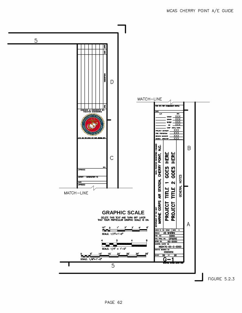
GRAPHIC SCALE


64
SECTION 6. SPECIFICATIONS 6.1 REQUIREMENTS FOR PREPARATION OF PROJECT SPECIFICATIONS The project specifications form a part of the contract documents. Format and general instructions for the preparation of project specifications are included in the current version of MIL-HDBK-1006/1, Policy and Procedures for Project Drawing and Specification Preparation (previously NAVFAC DM -6). Specifications are required to be in the current version SP ECSINTACT format, based on Cherry Point guide specifications (copy can be obtained from PM), edited and supplemented to suit the particular project. Scan all computer disks submitted for viruses using a commercial anti -virus scanning program. The specifi cations shall be as brief as possible, definite, and free of ambiguities and omissions, which might result in controversies and contractor claims for additional compensation. 6.2 GUIDE SPECIFICATIONS Guide specifications of NAVFAC NFGS Series shall be u tilized in the preparation of project specifications. These specifications are available on the CD -ROM as described herein. Any hard copy required by the A&E may be printed therefrom. Hard copy may also be obtained from Standardization Documents Order D esk, Building 4D, 700 Robbins Avenue, Philadelphia, PA 19111 -5094. The A&E shall carefully edit, modify, and supplement these sections and prepare additional sections in the same format to ensure they are coordinated with the project design. The latest g uides, the NFGS series, should be considered as standards for format where they differ from earlier guides. NAVFAC guide specifications in SPECSINTACT format are available through the National Institute of Building Sciences (NIBS) per the following: - Compact Disc (CD) that holds the equivalent of 250,000 pages of information and
is readable on CD-ROM drive of computer. - Information on obtaining subscriptions to Construction Criteria Base (CCB)
containing SPECSINTACT may be obtained from the foll owing: NATIONAL INSTITUTE OF BUILDING SCIENCES ATTN CCB 1090 VERMONT AVENUE NW SUITE 700 WASHINGTON DC 20005 Telephone: 202-289-7800 NOTE: It is imperative that the A&E discuss SPECSINTACT features with the PM prior to beginning any sp ecification preparation so that an agreement can be reached regarding the proper version of SPECSINTACT to use for a specific project. This will minimize or eliminate rework of specifications following a re -issuance of the CD-R.

65
6.3 REFERENCES The current version of Military Bulletin 34 (MIL -BUL-34) (previously NAVFAC P-34) lists all current Federal and Military Specifications and industry and technical society specifications commonly used in Navy construction & repair work and which are referenced in NAVFAC guide specifications, residing on the CD -R. It is also available from Standardization Documents Order Desk, Building 4D, 700 Robbins Avenue, Philadelphia, PA 19111 -5094. It is essential that the A&E become thoroughly familiar with existing design c riteria and publications that are referenced in the guide specifications before they are referenced in the project specifications. Before actually referencing one of these specifications, the following points should be resolved: a. Does the amount of material and the nature of the project justify referencing the publications and testing required therein (particularly for materials on which such tests are not common)? b. Do the referenced publications cover material of a quality and type suitable for the service required? In referencing publications, the following rules should be followed: a. Do not copy portions of publications in the project specifications, except where applicable portions are short in length and remainder of the publications do es not apply to the specific project. In this case, do not list or reference the publication in the project specification. b. Use the current version of the publication and avoid reference to specific paragraphs in the publication unless the paragraphs referenced are the only portions of the publication that are applicable to the specific project. c. Avoid repeated references to a publication within the same section. d. Read carefully all Notes on the Use of the Publication. e. Specify types, classes, weights, and similar applicable characteristics required to ensure accurate description. 6.4 SPECIFYING NEW MATERIALS From time to time requests are made to consider the use of materials, which are comparatively new. The fact that a material is new should not necessarily bar its use, provided it has been thoroughly investigated. Neither should previous use place a material in an approved category. Usually, service records of new materials do not exist. It is necessary, therefore, to base judgments upon laboratory tests. Such tests, in order to be accepted as authoritative, should be made by impartial qualified laboratories. Tests conducted by laboratories employed by manufacturers do not always show possible

66
defects in the material tested. Unless a material is tested under the conditions of actual use, or comparisons are made under like conditions, the results are not conclusive. Most reputable manufacturers will furnish readily all requested information and answer all reasonable questions. Unless the manufacturer of a new material furnishes factual data sufficient to evaluate the material, it should not be considered for use. If a material is considered for use, a suggested competitive-type specification should be obtained from the manufa cturer. Such a specification must be analyzed and revised as necessary to assure that a competitive, good-quality product will be obtained. 6.5 PROPRIETARY AND RESTRICTIVE REQUIREMENTS a. Proprietary Specifications. The restrictions below are containe d in the Federal Acquisition Regulations (FAR) and certain statutes. From time to time a situation arises in which only a single product will perform the required function. In such cases, the A&E should forward a request to the PM fully justifying use of the sole source product. Proprietary or restrictive requirements shall not be used unless it is conclusively established that no substitute will serve the purpose. Timely submittal of the request is required to avoid delays in the work. If such authori zation is granted, the item should be specified by manufacturer's name and catalog number, followed by "notwithstanding any other provision of this contract, no other product will be acceptable" or language of similar import. This is necessitated by the C ontract Clauses, which permit substitution of any supposedly equal product unless such language is used. Use of proprietary items is prohibited unless formal written approval is obtained. b. “Or Equal” Specifications. Specifying items by naming accepta ble commercial products followed by the words "or equal" is permitted under the following conditions: (a) there are no Government Guide specifications for the item, (b) the item is a minor part of the construction project, and (c) the item cannot adequately be described because of technically involved construction or composition. In each instance a minimum of three manufacturers shall be included in the description followed by the words "or equal". The essential features (salient characteristics) of the item must also be set forth in sufficient detail to establish the basis upon which the equality of non -listed products will be determined. c. Experience clauses shall not ordinarily be included in the technical specifications. Experience clauses that occur in NAVFAC guide specifications have been reviewed and approved by a Level I Contracting Officer and may be used without further approval or waiver. 6.6 PRE-QUALIFICATION STATEMENTS AND EXPERIENCE REQUIREMENTS Projects utilizing conventional construc tion methods and materials cannot be restricted with respect to bidders, building systems, or materials. Occasionally a project is unique in nature or has special circumstances that dictate use of unconventional methods. For these projects the A&E shall identify and document to the PM the need and basis of need for unique construction or state-of-the-art procurements. Documentation

67
shall include a description of the unique features, the reasons for their uniqueness, and a description of the pre-qualifica tion and experience requirements necessary to adequately construct these features. Documentation should be forwarded to the PM as soon as possible in the design process. 6.7 PHRASEOLOGY The following instructions that relate to common errors in phrasin g have evolved from NAVFAC experience with A&E specifications: a. Under “Requirements”, do not use the phrase "the work consists of" – instead use the phrase "the work includes". Drawings should show scope if necessary to list certain parts. b. In lieu of reference to the accompanying drawings or the Contracting Officer, use the words "as shown", "as indicated", "as detailed" or "as approved", "as directed", "as permitted" - do NOT use the words "as shown on drawings" or "as approved by the Contracting Officer". That clause of the Contract Clauses entitled “Specifications and Drawings for Construction” defines the meaning of these and similar terms. c. Do NOT use the expression "to satisfaction of the Contracting Officer" or "satisfactory to the Contracting Officer". The contract states specifically that all work must meet the approval of the Contracting Officer. d. There are two parties to the contract - (1) the Government, represented by the Contracting Officer and (2) the Contractor. Therefore, do NOT use such expressions as "subject to the approval of the architect", "when in the opinion of the architect", "this contractor", "masonry contractor", or "subcontractor". Do not use the term "owner" - use the term "Government". e. Do NOT use etc.; the term is too imprecise for bidding and inspection purposes. f. The use of the expression "as indicated on the drawings" is very seldom necessary; the fact that a detail is on the drawings makes it unnecessary to mention it in the specification. If the expression is used and the item is not shown, the contractor is not required to provide it. g. Do NOT use expressions such as "The work required shall include, unless stated specifically otherwise, the provision of all materials for the installation o f all concrete, including reinforcement necessary to the construction and completion of the work per the drawings, the specifications, and the intent thereof". Since the drawings indicate clearly the exact limitations of the several classes of work, defin ing the limits of work within the specifications is superfluous and may be contradictory by failure to mention something shown clearly and intended to be included.

68
h. Minimize the use of cross -references and in NO case use paragraph numbers for this purpose. If necessary to refer to a particular paragraph, do so by its title and the section number and title under which it is to be found. Cross -references of the following type are totally unnecessary - "Painting of the wood work is covered under "'Painti ng'" or "painting is specified hereinafter". i. Do NOT place upon the contractor the responsibility for the possible inaccuracy of, or the lack of, information on the part of the Government; e.g., never use sentences similar to "although the drawings in dicate approximately the conditions that are likely to be found, bidders should satisfy themselves as to the actual conditions, for while they are believed to be shown, the Government does not guarantee the accuracy of the information given and the bidder shall assume all responsibility in the use of such". Remember that the Government is responsible for the accuracy and sufficiency of the information it gives to bidders or contractors and the A&E is in turn responsible to the Government for that same inf ormation. It will be necessary to establish in the project specification a definite basis of bid. For example, on a roof rehabilitation project where the extent of defective construction is unknown, the specification shall set forth, as a basis of bid, a definite amount of work to be performed and provide for adjustment per the Contract Clauses if the extent of work varies from the amount stated under the basis of bid. j. Do not include warranties in technical sections unless they are for more than one year, and generally not unless they are included in the NAVFAC guide specification. A one-year warranty is covered in the Contract Clauses. k. Do NOT set up a paragraph in the various sections entitled “Work not Included”. Specify the work that is incl uded under the respective sections. l. Specifications should clearly delineate equipment, ducts and piping systems that are required to be insulated. The phrase "insulating all ducts except in conditioned spaces" has resulted in differences of opinion a nd claim situations; also all duct systems should be appropriately designated as supply, exhaust, fresh air intake, or return to further clarify insulating requirements. 6.8 MISUSE OF WORDS a. Do NOT use the phrase “Correct any defects" – instead use the phrase "Correct all defects". b. Do NOT use the phrase "Paint sheet metal on either side" – instead use the phrase "Paint sheet metal on both sides." Either implies a choice. c. Do NOT use the phrase "It shall be free from defects of workmanship and material which would impair its strength or durability." The use of "or" for "and" or "and" for "or" in this sentence would result in a meaning not intended.

69
d. Do NOT use "and/or". The courts have considered this phrase to be intentionally ambiguous and, therefore, to be interpreted in favor of the Contractor.
e. Use statements that are definite and do not contain words/phrases that may be ambiguous. Examples:
"Remove the equipment from the building during the alterations and reinstall the
equipment after completion of the alterations." Do NOT use "Remove and replace the equipment as indicated." "Replace" can mean "put back" or "reinstall".
"Remove the existing culverts and reinstall the culverts in the new locations." Do
NOT use "Replace the existing culverts as indicated on the drawings." "Remove existing and provide electrical wiring." Do NOT use : "Replace the
electrical wiring" as this implies reinstallation of the old wiring. f. "Provide" is defined in the Contract Clauses as "fu rnish and install". When material or equipment are furnished by the Government directly or under other contracts for installation by the contractor, the term, "install" should be used; however, the contractor may be required to "provide" foundations, fastenings, etc., for the installation. If the word "install" is used alone, the bidder or contractor has a right to assume, on the basis of the definition cited, that the Government will "furnish" the materials in question. g. Certain terms and designation s of work phases, rooms and areas commonly used in Naval activities should NOT be used in construction specifications. Examples: Bulkhead (for wall), deck (for floor), ladder (for stair), head (for toilet), galley (for kitchen), overhead (for ceiling), etc. h. Provide statements of direction as opposed to statements of information. Examples: “wall shall be painted" should read "paint the wall." "To be ...", "shall be ...", "will be ..." does not affix responsibility. 6.9 USE OF ABBREVIATIONS AND SYMBOLS In general, abbreviations should be avoided except those that are generally understood and accepted and can be used economically: e.g., psig, cfm, kw. (The use of ft., in., lbs., %, do not offer great savings). The use of symbols is undesirable fo r three basic reasons: (1) most are difficult to produce on a typewriter; (2) they frequently have more than one meaning; (3) the typist may not know what is intended and therefore type an improper symbol. Feet ('), inch ("), degree (o), pound and number (#), should be written out, except that number may be abbreviated (No.). In the text it is preferable to spell figures except where they give dimensions, for example: "Ten buildings", "100 feet long"; however, "one" and "zero",

70
where used singly shall a lways be spelled out. Never use both the written and numerical figure, ten (10). 6.10 STANDARD PLATES, SKETCHES, AND DETAILS Except as provided in Section 5 for sketches in amendments, all plates, sketches, and details shall be provided on the drawings and NOT in the specifications. 6.11 SUBMITTAL PROCEDURES a. 35% submittal (outline specifications). Before starting work on project specifications, the A&E personnel who prepare the project specification shall confer as necessary with the PM to ensure a clear understanding of current Government requirements. After the preliminary architectural and engineering studies have been completed and the basic features of the proposed design have been established, but before any detailed preparation of project specifications is begun, an outline specification shall be submitted as a part of the 35% submittal. The outline specification should list each anticipated section of the project specification along with appropriate statements applicable to each sectio n. The outline specification should state all basic construction items and specific types of materials, and should be complete enough to enable Cherry Point to ascertain that the proper guide specifications are being used and to provide appropriate guidan ce to the A&E. Where the specification writer is editing documents within the computer, the use of hard copy is optional and the document to be furnished for review or final bond manuscript may be developed entirely from the specification processor. In a ny event, the Guide Specification to be used must be approved at the 35% stage. The outline specifications should describe any special conditions of service and site conditions inherent in the project. The following sample outline specification illustrat es the type of information desired:
SAMPLE OUTLINE SPECIFICATION Division 1 - General Requirements Section 01110 Summary of Work 01140 Work Restrictions 01200 Price and Payment Procedures 01300 Submittal Procedures 01310 Administrative Requireme nts 01450 Quality Control 01500 Temporary Facilities and Controls 01525 Safety Requirements 01575 Temporary Environmental Controls

71
01770 Closeout Procedures 01781 Operation and Maintenance Data Division 2 - Site Work Section 02220 Site Demolition: Remove existing partitions, doors, plumbing fixtures and lighting fixtures
as indicated. 02315 Excavation and Fill: Excavating, back filling, and compacting for buildings and utilities.
Grading for grass areas. 02361 Soil Treatment for Subterranean Termite Control: Treatment for building. 02510 Water Distribution: Buried water-piping service to building 5 -foot line. 02530 Exterior Sanitary Sewer System: Sanitary gravity sewer service to buildings 5 -foot line. 02554 Exterior Aboveground Steam Distribution System: Above ground piping, buried pre -insulated piping, and manholes. 02556 Exterior Buried Pumped Condensate Return System: Buried preinsulated piping and manholes. 02921 Turf: Seeding fertiliz ing all newly graded finish earth surfaces and other areas
disturbed by site operations. Division 3 - Concrete Section 03300 Cast-in-Place Concrete: Spread footings, slab on grade, walks, and equipment pads. Division 4 - Masonry Section 04200 Unit Masonry: Face brick and concrete masonry unit (CMU) cavity walls, CMU
partitions. Division 5 - Metals Section 05310 Steel Decks:
72
Medium Rib, shop primed, for new addition. 05500 Metal Fabrications: Miscellaneous anchors, fasteners, lintels , railings, and pipe sleeves. Division 6 - Wood and Plastics Section 06200 Finish Carpentry: Nailers and blocking at roof, vanities and counter tops, cabinets for
coffee mess. Division 7 - Thermal and Moisture Protection Section 07112 Bituminous Dampproofing: Cold applied, for cavity face of interior width of cavity walls. 07220 Roof and Deck Insulation: Polyisocyanurate or composite polyurethane, C = 0.03, mechanically
fastened to metal deck. 07240 Masonry Wall Insulation: Polyisocyanurate, polyurethane, or polystyrene, R-value not less than 5. Division 8 - Doors and Windows Section 08110 Steel Doors and Frames: Grade III, Extra Heavy Duty, throughout. Hot-dip galvanized for exterior
doors. 08520 Aluminum Windows: Double-hung, thermal break, clear anodized or white enamel finish. 08710 Finish Hardware: Bored locks, push-pull toilet room doors, stainless steel finish except
hinges may be chromium plated. 08800 Glazing: Insulating glass units for windows, wire glass for doors. Division 9 - Finishes Section 09100 Metal Support Systems: Steel stud partitions and suspended ceilings. 09250 Gypsum Board: Regular, 1/2 inch, for partitions and ceilings where indicated.

73
09651 Resilient Tile Flooring: Vinyl composition tile, 1/8 inch thick. 09680 Carpet: Nylon loop pile, direct glue down without cushion. 09900 Paints and Coatings: New surfaces and existing painted surfaces, which are damaged during
performance of the work. Flat latex in offices, semi-gloss enamel in corridors.
Division 10 - Specialties Section 10153 Toilet Partitions: Metal, overhead braced, baked enamel finish. 10800 Toilet Accessories: Stainless steel tissue, soap, and towel dispensers, glass mirrors with
stainless steel frames. Division 11 - Equipment This Division is not used. Division 12 - Furnishings Section 12490 Blinds, Venetian : One-inch slats for windows. Division 13 - Special Construction (Describe applicable requirements) Divis ion 14 - Conveying System (Describe applicable requirements) Division 15 - Mechanical Section 15050 Basic Mechanical Materials and Methods: 15080 Insulation for Mechanical Systems: Fiberglass duct insulation, fiberglass, polyurethane, or Poly isocyanurate
pipe insulation.

74
15400 Plumbing: DMV piping, domestic water piping, flush valve water closets, and
counter top lavatories. 15730 Unitary Air Conditioning Equipment: Roof top air conditioning unit with steam heating coil and direc t
expansion cooling coil, galvanized steel ductwork. Division 16 - Electrical Section 16050 Basic Electrical Materials and Methods: 16273 Pad Mounted Transformers: Pad mounted transformers and metering. 16302 Underground Electrical Work: Plastic duct, concrete encased; manholes and handholes; high -voltage
cable. 16360 Low-Voltage Switchgear and Secondary Unit Substations: 16402 Interior Wiring Systems: Copper conductors in rigid steel conduit, except where electric metallic
tubing i s permitted; panel boards. 16510 Interior Lighting: Fluorescent fixtures, two lamp and four lamp, surface mounted; high
pressure sodium fixtures; emergency lighting. 16520 Exterior Lighting: High-pressure sodium fixtures; low-pressure sodium fixtures; fiberglass,
concrete, steel, aluminum and wood poles. b. Pre-final submittal (complete specification). Specifications for the pre -final submission shall be complete to the best of the A&E's knowledge, with all elements thoroughly checked & coordinated with the drawings, and with sufficient detailed information to permit accurate bidding & construction of the project. Particular emphasis shall be placed on coordination of the various elements of the specification where portions are prepared under subcontract to the A&E contract. Specifications shall be prepared using the current version of SPECSINTACT software. Do NOT translate specifications to another software. For the pre-final submittal of the specification, NAVFACENGCOM guide specificati ons shall be edited and photographic copies submitted for review. Editing will be accomplished electronically using the current version of SPECSINTACT software and then reproducing copies of the printouts. Additional specifications not covered by NAVFACE NGCOM guide specifications shall be typed in SPECSINTACT format and submitted for review. All specifications shall be bound in one single volume.

75
Cherry Point shall edit all Division One sections of the specification and provide a review copy to the A&E with the pre-final review comments. The A&E shall provide Cherry Point with construction contract duration time and project special scheduling requirements with the pre -final submittal. The standard 16 Division Construction Specifications Institute form at shall be used on all projects. On small projects or projects of a special nature using only a few divisions, the listing of non -applicable divisions may be omitted. Control Diagrams - Provide a written sequence of operation for each mechanical and electrical control system stating explicitly how systems are to function. Give all pertinent data regarding safety, alarms, indicators, and control parameters. The sequence of operations may be shown on the control diagrams in lieu of in the specification. c. Final submittal. Following the review of the pre -final submittal, comments and corrections to be included in the final submittal will be furnished to the A&E by Cherry Point. The final submittal to Cherry Point shall consist of one electronic copy on CD-R of the complete specification in SPECSINTACT format and two bound printed copies. In addition, provide one copy of project submittal register and test requirements report, as well as submittals processing, reference processing, and related operati ons. PROJECT SUBMITTAL REGISTER: Provide the submittal register, which is a list of all submittals required for the project, using the current version of SPECSINTACT software. TEST REQUIREMENTS REPORT: Provide the test requirements report, which is a list of all testing required for the project, using the current version of SPECSINTACT software. 6.12 BID ITEMS In order to ensure an award being made within available funds, additive bid items will be established by the A&E in conjunction with t he PM and the station; however, additive bid items are not required whenever the project cost estimate is clearly within the funds available. In composing bid items, the base bid must provide a usable facility. Work increments for additive bid items sho uld be selected which can logically be separated from the project without rendering the facility unusable. It is intended that the base bid with all additive bid items will provide the maximum usable facility for the funds available. Additive bid items shall be arranged so that the most essential portion of the work is added first. Succeeding items will be cumulative for purposes of determining if the

76
project is within the available funds; however, to provide latitude in selection, each additive bid ite m shall be independent of others, where practicable. The number of bid items and the estimated additive amounts per item will depend upon the nature of the project. Where feasible and practicable, there will normally be not more than three bid items. E ach estimated additive increment should tend to approximate 5% to 10% of the estimated base bid. There shall be no more than four additive items without specific approval of the Commander of the Atlantic Division, Naval Facilities Engineering Command. Bi d items shall not be indicated on the drawings or referenced anywhere in the Specifications without prior approval of the PM. Do not use the term alternate to represent additive bid items. Deductive bid items are not permitted. 6.13 FEDERAL AND MILITARY SPECIFICATIONS The importance of obtaining the necessary Federal and Military Specifications cannot be over-emphasized, particularly when the A&E has shop drawing approval responsibility. Federal and Military Specifications that are referenced in MIL -BUL-34 are included in the CCB available through NIBS. These and other Federal and Military Specifications may be ordered from: STANDARDIZATION DOCUMENTS ORDER DESK BLDG 4D 700 ROBBINS AVENUE PHILADELPHIA PA 19111-5094 6.14 INTERIM SPECIFICATION REVISIONS (ISR) LANTNAVFACENGCOM maintains a system known as interim specification revisions (ISR). This document has changes needed in an NFGS until such changes can be incorporated into the guide specification. These changes must be incorporate d into projects. Contact the PM for additional information.

77
SECTION 7. COST ESTIMATES 7.1 GENERAL A detailed cost estimate is required with each submittal. All estimates shall be computer or manually prepared using a cost estimating method as appr oved by the PM. Scan all computer disks submitted for viruses using a commercial anti -virus scanning program. The estimate detail for each submittal shall be consistent with the level of design required for that submittal. Accurate quantity take -off, inclusion of all appropriate cost systems, and accurate unit prices for the project's geographic location are fundamental to the development of a good cost estimate. The A&E's objective is to develop a final estimate that will be within 10% (+/ -) of the lowest responsible bid. This requires responsible pricing, experienced judgment and an accurate assessment of the market conditions. When this objective is not met, it is necessary for bid evaluation that the A&E submit a comparison of cost between the lo w bid and the final A&E estimate. Reasons for major differences, sorted by specification division, must be stated with a recommendation to award or reject. This bid analysis must be received within one week after notification that it is required and is t o be provided at no additional cost to the Government. Properly prepared cost estimates provide a check of plans and specifications for construction, coordination conflicts, discrepancies, omissions and cost control. Cost estimates are used by the Government to establish budgets, verification of contract bid price, and to develop historical data for future budget estimates. Final Government estimates are to be marked by the A&E with "For Official Use Only." Access to or disclosure of information withi n the estimate is limited to those personnel whose official duties require knowledge of the estimate. 7.2 PROJECT DESIGN ESTIMATES The estimate at each submittal is expected to reflect the A&E's best information and experience. Expected bid opening dat e shall be established by the PM. Pricing must reflect all requirements of the contract plans and specifications. The individual preparing the estimate should verify that all specification requirements are priced with particular attention to Division One and the wage rates. Size, material quality, and type of item shall be part of the description to enable unit cost verification without constant reference to drawings and specifications. 7.2.1 35% DESIGN Preliminary estimate based on materials take -off for this submittal shall reflect cost based on reasonably accurate take-off of materials/systems consistent with the level of design. For those elements of the project where the status of design does not permit a reasonably accurate

78
take-off of quantities or firm pricing of individual items of work, systems unit prices may be used. Lump sum costs are not acceptable. Use of empirical costs shall be minimized. Separate estimates will be prepared for each new non -identical building, structure, or addition costing over $50,000 contract cost. Costs of alteration work to existing buildings will not be included with the building addition costs. When one construction contract contains more than one type of work (i.e., new construction, repair, equipment insta llation, etc.), the estimate shall be structured such that each type of work is identified separately. In addition to a master summary sheet, each type of work requires a separate summary sheet. Costs from these separate summary sheets must be directly t ransferable to the master summary sheet. When work is a combination of more than one project, the cost estimate must be further separated per project, summarized per project, and transferred to the master summary sheet. Beginning with the 35% estimate, a separate line item must be included for Contract Quality Control (CQC) projects. CQC is a contractor responsibility inspection system added to most projects that exceed $2,000,000 in construction cost. Unless directed otherwise, allow 3% of the construction cost for CQC. 35% estimates should monitor the estimated construction cost during design. The 35% estimate, through adjustments, should monitor the estimated construction cost until the pre -final estimate is prepared. It is very important that if t he estimate indicates that the design exceeds the allocated funds, the PM be contacted for instructions. 7.2.2 PRE-FINAL DESIGN For all projects over $500,000, and for all new buildings or additions over $100,000, a CES or comparable format estimate is required. Unique projects not readily adaptable to CES or comparable format may be discussed with the PM. Hard copies of estimates will be required for each submittal. The CES program or comparable format, database and User's Guide are included on the C CB compact disc. Call the PM, if the CCB is not available. Include the following reports (menu selections) with each submittal. a. Input listing (sorted) b. Summary - Yes (choose "No" for summary %) c. Mark-up d. Modifier e. Detailed Estim ate with Systems Sort f. Spec Section Summary

79
Contact should be made with the PM prior to the pre-final submission to reconfirm programmed construction costs for the contract. Where A&E estimate exceeds programmed construction costs, recommendations for cost reduction or proposed bid items must be provided with the pre-final submission. 7.2.3 FINAL The final estimate submittals shall include the complete estimate on CD -R, the same as the pre-final except for correction/inclusion of pre -final comments.

80
SECTION 8. POST DESIGN SERVICES 8.1 CONSULTATION DURING CONSTRUCTION 8.1.1 GENERAL The A&E shall provide consultation services during the construction period as well as the design period. Such consultation may or may not be reimbursable as follows: a. Non-Reimbursable Consultation: Under paragraph 3(g) of Section 01011 General Paragraphs of the A&E Contract, the A&E shall promptly furnish consultation services without additional compensation. Such consultation typically occurs in the form of a Request for Information (RFI) from the ROICC. Typically, RFIs include providing clarification of the intent of the drawings and specifications in response to questions, which routinely arise during the course of construction. These may result in preparation of amplifying drawings, specifications, amendments, change orders and cost estimates to correct errors, omissions, inconsistencies between drawings and specifications, conflicts in dimensions, lack of detail or poor design quality in the draw ings and specifications. Amplifying drawings, specifications, amendments, change orders and cost estimates shall be prepared per the provisions and standards set forth in this A&E Guide. In such cases, the A&E shall assure through discussions with the ROICC the timing required for preparation of such documents to minimize delay to the construction. It is expected that the A&E will provide a response to an RFI not later than three (3) working days after notification. Where the response to an RFI requires additional time, the A&E shall notify the ROICC as to the expected date of response. b. Reimbursable Consultation: In addition to non -reimbursable consultation, reimbursable A&E services may be required for specialized consultation with Cherry Point an d ROICC personnel either at the site of construction or in the A&E's office regarding matters of a nature not included under "General Paragraphs" of the A&E Contract. If reimbursable consultation is required, the PM will address during A&E contract negoti ations. 8.1.2 CONSULTATION REPORTS 8.1.2.1 EVALUATION OF CONTRACTOR PROPOSED EXCEPTIONS OR VARIATIONS TO THE CONTRACT DOCUMENTS In addition to the general requirements, consultation reports on A&E evaluation of construction contractor proposed exceptions or variations to the contract documents shall address: a. Whether the proposed substitution is of equal, better, or lesser quality than the design requirements. b. If of lesser quality, the difference in value.

81
c. If of equal or better quality, the advantages to the Government in accepting the substitution at no change in contract price. 8.1.2.2 EVALUATION OF CONSTRUCTION CONTRACTOR VALUE ENGINEERING CHANGE PROPOSALS (VECPs) The purpose of a VECP is to achieve savings in cost by adjusting the de sign so as to permit more economical methods and materials of construction and still maintain the operational, functional and aesthetic quality of the facility. Note that a construction contractor VECP differs from a construction contractor proposed variation or exception to the contract documents in that a VECP must maintain at least the same level of quality as in the original design while a proposed variation or exception could lower the quality of construction. Under the VECP program, the contractor and Government share in the savings resulting from acceptable proposals while a full credit (deduct) in the construction contract price is taken for approved variations or exceptions which are of lesser quality than the original design. In addition to the general requirements, consultation reports on A&E evaluation of VECPs shall include the advantages and disadvantages of the VECP, and economic analysis & justification for recommending approval or rejection of the VECP. In order to avoid tacit delays to construction, Government processing time for VECPs is held to 21 calendar days from the date the ROICC receives the VECP package from the contractor. Accordingly, the A&E shall complete and forward consultation reports on VECPs to the ROICC and PM within five (5) working days from the time of receipt. When the VECP is of the nature that the response requires additional time, the A&E shall notify the ROICC as to the expected date of responses. 8.2 SHOP DRAWINGS/SUBMITTAL REVIEW To the extent negotiated in the design contract or task order, checking of shop drawings/submittals is the A&E’s responsibility. The A&E shall provide and use a shop drawing approval stamp similar to the one shown in Figure 8.1 to process shop drawing submittals. NOTE: Shop drawings/submittals shall include all submittal descriptions as listed in Section 01300, "Submittals" of the construction contract specifications. 8.2.1 GOVERNMENT IS APPROVING AUTHORITY The construction contractor for the project has been instructed to forward to your office for review all shop drawings, manufacturer's data, certifications and samples, except those designated for LANTNAVFACENGCOM's approval, as follows:

82
TRANSMITTAL FORM SUBMITTAL SAMPLES 4 7 * *Quantities specified The procedure for handling these submittals is as follows: a. Acceptable Submittals - If the submittal complies with the contract requirements, it shall be stamped APPROVED, dated and legibly signed by an authorized person. If minor revisions were made by the contractor in order to make the submittal comply with the requirements, it shall be stamped APPROVED, dated and signed. If minor revisions are made by the A&E in order to make the submittal comply with the contract requirements, it shall be stamped APPROVED-AS-NOTED, dated and signed. The revisions must be identically marked on all copies of the submittal. The individual making the change must initial each revision. The reviewer's section of the transmittal form, including the endorsement returning the submittals to the contractor, shall be completed, and both transmittal form and submittals distributed as follows: TRANSMITTAL FORM SUBMITTAL SAMPLES Contractor 1 3 * FED 2 3 1 A&E 1 1 0 Total 4 7 1* *Additional quantities returned to contractor Facilities Engineering Department (FED) will distribute one copy each of the transmittal and submittal to the PM and one copy of the transmittal, two copies of the submittal, and the sample to the ROICC. b. Unacceptable Submittals - If the submittal does not comply with the contract requirements and cannot be made to comply by minor revisions and the contractor has not proposed and supported a deviation from the contract requirements, the submittal shall be stamped DISAPPROVED, dated and signed. The reviewer's section of the transmittal form shall be completed and both transmittal forms and submittals distributed as follows:

83
TRANSMITTAL FORM SUBMITTAL SAMPLES Contractor 1 4 ALL FED 2 2 0 A&E 1 1 0 Total 4 7 *Additional quantities returned to contract or FED will distribute one copy each of the transmittal and submittal to the PM and one copy to the ROICC. c. Proposed deviations from the contract requirements - If the contractor proposes a deviation from the contract requirements, it must be support ed by the following information: (1) Reason for the proposed substitution. (2) If material or equipment is unavailable, document efforts made to procure. (3) Complete technical data on the proposed substitution, sufficient to determine acceptabili ty. (4) Acknowledge that all changes caused by the proposed substitution will be the responsibility of the contractor and at no additional cost to the Government. (5) Proposed change, if any, in the contract price and/or time. These submittals shal l be reviewed but not stamped. The A&E comments/recommendations and reviewer action shall be noted on one copy of the transmittal forms, the unstamped submittals and cost estimate shall be forwarded to the PM. Upon completion of review by Cherry Point, the submittal will be stamped, dated and signed, and distribution made to the contractor, ROICC, and A&E. 8.2.2 MISCELLANEOUS SUBMITTAL REVIEW ASPECTS a. When a submittal must be revised by the A&E due to such reasons as changed Government requirements or correction of design deficiency, it must be forwarded to the PM with an explanation for the new requirements and the estimated change in contract price for the contractor to comply with the new requirements. b. Only certifications which state that the item submitted complies with the contract requirements are acceptable. A statement that the item submitted is equal to or better than the specified item will not suffice.

84
c. When a submittal cannot be reviewed within two weeks, the ROICC must be advise d of the estimated date of review completion. d. Mail Cherry Point's submittal copies to the address shown, ATTN: Code SUB. 8.3 OPERATION AND MAINTENANCE SUPPORT INFORMATION (OMSI) (OPTION) To the extent negotiated in the design contract or task order, preparation of OMSI manuals is an A&E responsibility. OMSI manuals are developed during construction of a facility to provide the Activity with clear, comprehensive data needed to safely and efficiently operate and maintain the actual products and systems built into a facility. The principal OMSI elements, which may be included in the manuals, are: Operation and Maintenance Manual * Overall system configuration and operation * System flow diagrams * Start-up, normal operation and sh utdown procedures * Normal operating temperatures, pressures, flow rates, etc. * Emergency operating and safety instructions * Preventive maintenance plan and schedule * Troubleshooting guide and diagnostic techniques * Repair and maintenance procedures, including spare parts, special tools and test
equipment * Environmental considerations * Training plan, staffing requirements and personnel qualifications * Removal and replacement instructions Operating Manual * System design discussion
* Procedures for normal start-up, operation and shutdown in manual and automatic modes * Floor plans and schematic diagrams for flow, piping and instrumentation * Control set points and calibration requirements * Procedures for abnormal/alternate operational modes
User Manual
* As-built record of product and O&M data, indexed by specification, location section * Basic descriptive data on facility; basis of design * Single line floor plans

85
* Utility connections and cut -off points * Special warranty data
* Expanded operation, maintenance and repair information for HVAC, fire protection and roofing systems All Military Construction Navy Projects (MCON) now require some degree of OMSI (min imum of User Manual) with the exception of projects such as Land Acquisition, Paving and Dredging. Projects requiring OMSI can be classified as either a Type A, B, or C. The standard package for each type of OMSI is as follows: Type A OMSI (1) Operation and Maintenance Manual (2) User Manual Type B OMSI (Do not use if maintenance and repair information is required) (1) Operating Manual (2) User Manual Type C OMSI: User Manual The degree of OMSI required will vary with the complex ity of systems and type of facility. a. Facilities having complex systems such as the following would normally require a Type A OMSI: Petroleum, Oil and Lubricant (POL) Transfer/Loading Facilities Large/Complex Computer Operations Center Training Facilities with Complex Systems Aircraft Maintenance Shops Missile Assembly and Maintenance Shops Ship Maintenance Shops Laboratories Central Refrigeration Plants Medical Facilities Command Communication and Operation Centers Power Plants Heating Plants Industrial Waste and Sewage Treatment Plants Water Supply, Treatment and Storage, Potable Plating Shops

86
b. Less complex facilities where proper operation of the facility or system is critical a Type B OMSI may be appropriate as follows (may require Type A OMSI if maintenance and repair information is needed): Operation and Training Facilities Miscellaneous/Utilities c. Rather simple facilities such as BEQ, BOQ, Chapels, Admin Facilities, Warehouses and Community Facilities us ually require a Type C OMSI. Depending on the complexity of a particular system, even a simple facility such as a Child Care Center could need a Type A OMSI to provide an OMSI Operation and Maintenance Manual for that system; e.g., Variable Air Volume (V AV) or Thermal Storage System. A project such as a hospital, however, would typically cover fifteen or more systems in the manual. Successful A&E preparation of an excellent quality OMSI manual requires that the specification include NFGS 01730, "Operat ion and Maintenance Data", and that it be properly referenced in the technical sections to specify "Data Packages" to be submitted by the construction contractor. The A&E preparing the OMSI manuals uses this data to develop comprehensive coverage of a system based on the as-built products in this facility. Three sets of all approved submittals (except samples) must be retained by the A&E for preparation of the OMSI manuals. The PM will advise the A&E of the type of OMSI needed for each project. However, A&E recommendations are solicited on changes to the OMSI type based on complexity of systems as design develops. Specific scopes of work for each OMSI manual are provided in Appendix A. 8.4 CATHODIC PROTECTION SYSTEM INSPECTION, TESTING AND ACCEPTANCE (OPTION) To the extent negotiated in the design contract or task order, the A&E's corrosion engineer may be required to act as the Government corrosion engineer in final inspection, testing and acceptance of the cathodic protection systems installed by the construction contract for the ROICC. Responsibility may include: a. On-site consultation with the ROICC on the critical stages of construction. b. Review of Construction Contractor's corrosion engineer cathodic protection system start-up survey report. c. Final inspection and testing of cathodic protection systems, approximately 30 days after construction contractor's report submittal, to verify the contractor's report and insure structure

87
protection levels are per National Association of Corros ion Engineers (NACE) recommended practices. d. Confirmation of interference current mitigation to other structures. e. Provide ROICC with "punch list" of construction contractor deficiencies on the installation of the cathodic protection systems. f. Prepare a final inspection report noting all test results to document levels of cathodic protection throughout the structure and to establish baseline parameters.

88
ATTACHMENT A CHERRY POINT CAD STANDARDS
Rev. Date 08/20/03 Point of contact at Cherry Point regarding these standards is Skip Conklin at (252)466-4780 or Phil Fisher at (252)466-4714. 1. Project file naming conventions. Files will be named the NAVFAC drawing number (i.e. 1234567.dwg). All other file names such as mappin g files shall be approved by Government PM. 2. All CAD file CD submittals shall have the following labeling on the CD -R. Item Description Example Disc sequence number Disc 1 of 2 A&E (Consultant) Company Name NO MISTAKES, INC. Construction Contract No. (A&E contract no. if no construction contract no.) N62470-00-C-2001 CP Project Number CP9900M FED File Number 1234 Building number drawings specify work on, if applicable Building 101 Disc Creation Date 4 July 2000 File na mes will be NAVFAC drawing number(s) 1234567.dwg 3. In general, follow the TSSDS National CAD standards. All specific standards shall be identified and approved by Government PM. Standards for facility design drawings will be different in many cases fro m those used for mapping. For layer names, the A&E (Consultant) shall provide hard copy of layer list to the PM. 4. Graphic drawing contents WILL be created at full scale (1:1 in model space) and plotted at 1:1 in paper space. Drawings WILL be prepared using font and text sizes as stated in paragraph 5.2 of this manual.
5. Each AutoCAD .dwg file (drawing sheet) shall have the file name & plotted scale (which will be 1:1 paper space) used to create the presentation hard copy listed in the lower right hand corner. 6. A&E will electronically submit a copy of all AutoCAD 2002 drawing files on CD -R, which will be left OPEN. 7. Block & referenced files may be used in the file creation; HOWEVER, the individual drawing files shall be BOUND together as ON E file prior to burning CD-R.

89
CHERRY POINT CAD STANDARDS
Rev. Date 08/20/03 8. For mapping and site plan creation of Cherry Point facilities -- All horizontal coordinates shall be N.C. State Plane (NAD83). All vertical points shall be USGS d atum (NGVD88). Above shall be used for all site plans unless approved otherwise. 9. Map and site plan accuracy: Horizontal (coordinate) and vertical location shall be within 6 inches of true location, at least 90% of the time. 10. Dates of all file c reations shall be shown. Files will be virus scanned by the A&E prior to submission. 11. Drawing formats and title blocks shall conform to Cherry Point CAD standards. PM will provide an AutoCAD 2002 electronic file of the current D -size format sheets. 12. Large files or a large amount of data will not be compressed using ZIP or similar routines. Compressed files will not be accepted by Cherry Point. Files will be delivered on CD-Rs that are readable on any standard CD -ROM drive that is part of a win dows based PC system. When burning CD -Rs, do NOT “close out” the CD. Leave it open for addition of more project data. 13. Use the TSSDS National CAD Standards as long as they are coordinated and approved by Government PM. 14. Data shall be Geographical Information System (GIS) ready and topologically correct. Files shall be properly geo -referenced using Cherry Point’s coordinates. For example, polygons shall be closed - there shall be NO over-shots or under-shots where lines meet or intersect. Currently, all mapping requests are produced from the Cherry Point GIS. The MCAS Cherry Point GIS Manager can be reached at (252) 466 -4524 for further GIS requirements or questions. 15. Upon receipt from outside sources, the PM will virus-scan ALL CDs/files using commercial anti -virus software.

90
CHERRY POINT CAD STANDARDS
Rev. Date 08/20/03
CAD LINEWEIGHTS SETUP PURPOSE: To review and assure a common understanding of the standard needed for our AutoCAD drawings. PROBLEM BEING SOLVED: As an AutoCAD .dwg file is converted to .PDF file, a process needs to be established to assure line weights are carried through. STANDARD: When starting a new AutoCAD drawing file, use the National CAD Standards for the line weight definitions. This will allow a con version to .PDF that carries forward the line weight (bold) that was anticipated when the drawing was drawn in AutoCAD. The National CAD Standard states AutoCAD users assign line weights to color. Example, if a user wants a heavy line (border line) they w ill have the color magenta set at .5mm or any thick value. Any line used then that is magenta will be printed bold. There is a standard plot style for this and the file is “NatCadStndMono.ctb”. The whole aim of layer/color standardization is to allow ease of communication with other professionals. A bold line created in California should be bold when printed in North Carolina.

91
Here is a look at the “NatCadStndFULL.ctb” file. This file has been adapted to accommodate Cherry Point’s plotter settings. Notice each color has a different line weight in mm. For example, color #7 (WHITE/BLACK) = .88 mm. This is the “Table View” of this file. With the above line weights white/black #7 will print larger than blue, which has a value of .5mm. To incorporate this standard in AutoCAD, the user must have the “NatCadStndFULL.ctb” file within the program files of AutoCAD (i.e. C: or D: \program files \AutoCAD LT 2002\plot styles\). Now whenever the user goes to the print screen in AutoCAD, they can select this new file for their pen assignments.
here is the color#
here is the lineweight value. select this area to enter value
HERE IS THE NAME OF THE PLOT STYLE FILE

92
PLEASE BE AWARE! To adapt printer settings for different applications, use “natcadstndfull.ctb” for AutoCAD .dwg full size prints; “natcadstndhalf.ctb” for AutoCAD .dwg half size prints (11x17), and “natcadst ndpdf.ctb” for Adobe Acrobat Writer PDF conversion.
here is the file nested within the correct program file.
program files

93
When you go to plot within AutoCAD, select this file as shown below. Now the plotter and acrobat writer will create your drawings with line weights, assuming the drawings were created using these color\line weight relationships.
here is the file for the new standard lineweights.
AUTOCAD PRINT SCREEN

94
ATTACHMENT B CHERRY POINT MECHANICAL STANDARDS
Date 12/20/99 Point of contact at Cherry Point regarding these standards is Robert Lawrence at (252)466-4706 or Paul Cline at (252)466-4707. 1. HVAC STANDARDS: a. Keep mechanical equipment (AHU's, EF's, etc.) off of roofs if at all possible. Mechanical designs must consider the fragility of roofs. Install mechanical equipment at ground level and screened from view. Discuss alternatives with architect. b. If equipment is installed on roofs, use equipment manufacturers standard curbs. c. Avoid routing pipes above lay-in ceilings, especially low temperature pipes (i.e., chilled water) subject to condensation/dripping. d. Install blow down valves on all strainers. e. Air handling unit filter access doors should be specified as hinged and lockable with quarter-turn or half -turn thumb screws. Do not specify or approve access panels that are unhinged and/or retained by sheet metal screws. f. Require contractors to provide maintenance with a listing of HVAC filters for each piece of equipment along with their dimensions (width, height, thickness) and types (permanent, washable, throwaway, etc.). Also, require filter information to be clearly displayed on the outside of each piece of equipment. g. Do not specify mineral fiber on flexible unicellular insulation on chilled water pipes. Use rigid insulation on chilled water pipes where such pipes are subject to being stepped on or damaged. Cellular glass insulation is preferred. Metal jacket should be utilized for exterior or high abuse areas. h. Do not use plastic pre-insulated pipe for buried dual temperature water distribution. Use pre-insulated copper pipe for such applications. i. Provide separate mechanical and electrical rooms with exterior, ground level entrances, if possible. j. Shop air compressors should not be installed within HVAC mechanical rooms as occupant access is prohibited by base maintenance to those spaces. k. All equipment l ocated within or outside mechanical rooms should be accessible for maintenance (including coils) and for removal with minimum disruption to occupants.

95
l. HVAC equipment should not be installed in attics, overhead, or above suspended ceilings, unless absolutely necessary. When dictated by necessity, provide access and floor space for maintenance. In addition, provide auxiliary coil drain pans below all cooling equipment and pipe separately from primary system. m. Avoid use of cooling towers. n. Electronic/Direct Digital Control (DDC) systems are the preferred HVAC control systems. If by necessity pneumatic controls need to be utilized, then associated air compressors shall be installed within mechanical rooms, inaccessible to occupants for periodic service/maintenance. For HVAC systems being replaced, verify the existence of Utility Management and Control (UMAC) (Coggins) interface devices. Where present, re -establish monitoring and control capabilities in new HVAC system. o. Equipment control cabinets should be located no higher than 5' above finished floor. Avoid locating in high humidity spaces such as mechanical rooms with steam equipment and piping. p. Avoid use of economizers (dry bulb or enthalpy) as locally high humidity conditions and poor control reliability prohibits successful use. q. All HVAC systems 7 tons and over should be interfaced with the station UMAC system. The current system employs the Coggins energy management system that is capable of load shedding during peak energy consumption. r. For HVAC systems utilizing gas (propane or natural) as heating source, ensure specifications for the HVAC unit require contractor to furnish unit compatible with gas source. 2. STEAM STANDARDS: a. Minimize the use of steam manholes. T hose that must be used are to be raised 12" above finish grade and provided with full grated top. b. Do not install steam pits within mechanical rooms. c. Equip steam manholes with steam ejector pumps. Add electric sumps where steam is turned off during the summer. d. Use schedule 80 black steel carrier pipes for buried steam condensate lines. e. Use welded valves in steam pits. Inside buildings, flanged valves are permitted. f. Use Link Seals on steam and condensate piping where they penetrate manhole walls.

96
g. Use in line filters before regulators on low -pressure steam. h. Specify steam control valve actuators that can withstand the heat conducted from steam lines and equipment.

97
ATTACHMENT C CHERRY POINT CIVIL STANDARDS
Date 12/20/99 Point of contact at Cherry Point regarding these standards is Phil Fisher at (252) 466 -4714. Specific Civil Engineering Specification Standards The purpose of Civil Engineering Specification Standards is to list the desired standards for materia ls and construction desired by the Civil Division, FED, MCAS, Cherry Point, NC. Cost data and contractors are listed where available. By SPEC Section, the changes are as follows: 0110 Location of Underground Facilities Paragraph 1.3 Location of Underground Facilities: Should read “It shall be the responsibility... Do not continue with excavations or installation of new work without resolving elevation discrepancies and conflicts.” 01140 Work Restrictions Roadway paving contracts. Add a special section to address restrictions and scheduling. Reference specification 979615 for a sample. Modify and tailor to fit project. Airfield contracts. Add a special section to address work restrictions and scheduling. Reference specification 967855 and 986254 fo r a sample. Modify and tailor to fit project. 01560 Environmental Protection Rubbish and household garbage shall be disposed of daily by the contractor, outside the limits of the Air Station at the contractor's expense in compliance with all local appli cable regulations. Local location for dumping is Craven County Landfill at Tuscarora . As an exception - use local Air Station garbage containers upon PM's approval. Also see Section 01575. 02220 Site Demolition Excess materials shall be disposed of ou tside the limits of the Air Station at the Contractor's expense in compliance with all local applicable regulations. The exception is to dispose of certain soils and broken pavements where indicated by the PM. 02231 Clearing and Grubbing Excess materials shall be disposed of outside the limits of the Air Station at the Contractor's expense in compliance with all local applicable regulations. Local location for dumping is C&D landfill in Havelock .

98
02301 through 02315: Earthwork and Excavation. (Note: Contaminated soils and groundwater subject to special handling and disposal requirements.) Borrow materials shall be provided by the Contractor from sources outside the limits of the Air Station. Excess materials shall be disposed of outside the limits of the Air Station at the Contractor's expense in compliance with all local applicable regulations. Local dumping local location is Tuscarora. Contractor may be able to find a cheaper location to place clean fill for less cost. Exception: dispose of certain contaminated soils using special methods – see other instructions. Structural fills: Use locally available material that meets specification requirements. Use flowable fill when the need for a material that is self -compacting will provide a quality product such as a road patch. Use #57 or #467 stone for working in a wet condition where dewatering is not practical. 02441 Trenchless Excavation Directional drilling - use HDPE pipe or CERTA-LOK PVC AWWA C900. 02510 Water Distribution Do not use glued joints on pipe that is 4 inch and larger. Storm Drainage As a rule, require as -built invert and structure elevations from the Contractor. There is no Navy design manual. LANTDIV uses a 10 -year storm for most civil projects and rational method. For airfield, use a 5 -year storm - reason is ponding is allowed in system as long as it is not on pavement. See Army technical manuals TM 5 -820 1 through 4 for drainage. Minimum size pipe preferred is 18” to avoid clogging. 02711 through 02723 Base Course Use geotextile/geogrid separator between base and subgrade where possible. 02741 through 02744 Asphalt Pavement Use pre-edited spec section. For patches, provide special spec section and plates. Use NCDOT 1-1 mix unless approved otherwise by the PM.

99
02751 and 02752 Concrete Pavement For forklift and truck areas, use 650-flex mix and 8 inch min thickness with reinforcement. 02761 Pavement Markings Use Thermoplastic for permanent long -term usage on streets and parking lots. Use acrylic latex paint for temporary markings. On street pavements, use adhesive applied centerline reflectors spaced 80 feet apart (normal conditions) on street pavements). Paint only with justification and approval for short -term street markings and airfield pavements. 02762 Joints, Reinforcements, and Mooring Eyes Mandatory - use silicone joint sealant on airfield pavements. Materials: CRAFCO ROADSAVER Self leveling silicone joint sealant (Note that Dow Corning 888 and 890 Silicone Joint Sealant. 888 for joints b etween concrete and 890 for joints between asphalt and concrete – has been pulled off market). All reinforcing rods will be ASTM A-615, Grade 60. 02785 through 02789 Asphalt Treatments Require rolling with pneumatic rollers to enhance quality. 02821 Chain Link Fences Use galvanized posts with galvanizing inside and outside. See AIRSTAORDER P5531.1 for fence requirements. Confirm compliance with BEAPS. Turf Use pre-edited sections to suit our soil and topological conditions and the time of the ye ar. Planting Seasons for Seed Spring = 1 March to 31 May Fall = 1 September to 31 October Temporary Spring and Summer = 1 April to 15 September Temporary Fall and Winter = 16 September to 31 March Seed Composition Spring = Coastal Bermuda, 100% by wei ght (centipede could be substituted) Fall = Coastal Bermuda, 100% by weight (centipede could be substituted) Temporary Seeding Winter: Kobe Lespedeza 30 Percent Secale Cereale 70 Percent Temporary Seeding Summer: German Millet 60 Percent Sericea Lespedeza 40 Percent

100
Planting Season for Centipede Sod: 1 March to 31 October Seed Rate: Spring and Fall 4 lbs / 1000 SF Temporary Seeding 10 lbs / 1000 SF Lime Rate 20 lbs / 1000 SF Fertilizer Rate 23 lbs / 1000 SF 02976 Pavement Membrane Layers 1. Unless otherwise approved, use a geotextile fabric separation between stone and subgrade soils for civil works. 2. Rubber & Paint Removal: Do not specify 100% removal of paint or rubber. Different sites will require different pressures for the removal process (due to age of deposits, type of pavement and deposits, etc.). A 3000-psi pressure will likely not remove sufficiently. A 5000 to 8000 psi is required to remove rubber. Limit pressure to 5000 psi or less if necessary to prevent damage to pavements (70% to 90% removal rates expected at that pressure). Greater than 5000 psi will likely damage asphalt pavement. Greater than 8000 psi will lik ely damage concrete pavement. Rubber removal at Cherry Point is a reasonable expectation. Cost expectation 1999 is $0.50 to $1.25 per SF. 03300 Concrete 1. For routine projects, use 4000 psi in lieu of 3000 psi. per ASTM C94. Cost at local plant is $68/CY. Structural: ASCE7 wind load is 130 mph (do not use NC Code of 110 mph). Bolts and Rebar available in metric sizes. Siesmic Zone 0 according to NC Code. 3. Civil Design Requirements Surveys: Unless approved otherwise, projects shall use State Plane coordinates, NAD83 for horizontal control and USGS vertical control, NGVD88 . Exceptions on a case by case basis for insignificant and small projects, projects may use a local control such as a project specific base line along a road centerlin e, etc. and a local TBM. For ease of construction layout, small projects may also locate new features from existing permanent features. Accuracy shall be equal to the datum used (second order for second order). Use local control and local TBM only when design cost savings are absolutely critical. NOTE: The acceptable conversion from NGVD29 to NGVD88 for all of Cherry Point is -1.04 . Horizontal and vertical control available: Cherry Point (Horizontal = NAD83 and Vertical = NGVD29) Bogue, Atlantic, BT11(Horizontal = NAD83 and Vertical = NGVD88)

101
Site Plans: Scale large enough to show all features clearly and avoid overcrowding. Normal site plan scales are 1:50, 1:40, 1:30, 1:25, 1:20 and 1:10. Site Plans and Survey Presentation: Electronic in AutoC AD, revision consistent with what FED is currently using (check with PM). Soil Borings: LANTDIV (Kerry Nothnagel) has historical files of Cherry Point boring logs. They are trying to move it into Cherry Point’s electronic GIS in next two years. They hav e an open end-boring contract with ECS that we can use. We also have historical records of boring logs in the form of record drawings; see 3 stick files or flat files. Airfield Pavements: LANTDIV (Darrell Bryan – DSN 8-8-262-4411 or commercial 757-322-4411) has an electronic database in PAVER of the airfield pavement characteristics. They also have the airfield in AutoCAD files including joint layout. We also have historical records of airfield pavements in the form of record drawings; see stick fi les or flat files.