Embed Size (px)
Citation preview
GUIDE FORMANAGING RISKS FROM
HIGH PRESSUREWATER JETTING
DECEMBER 2013
Safe Work Australia is an Australian Government statutory agency established in 2009. Safe Work Australia consists of representatives of the Commonwealth, state and territory governments, the Australian Council of Trade Unions, the Australian Chamber of Commerce and Industry and the Australian Industry Group.
Safe Work Australia works with the Commonwealth, state and territory governments to improve work health and safety and workers’ compensation arrangements. Safe Work Australia is a national policy body, not a regulator of work health and safety. The Commonwealth, states and territories have responsibility for regulating and enforcing work health and safety laws in their jurisdiction.
ISBN 978-1-74361-356-6 [PDF]
ISBN 978-1-74361-357-3 [DOCX]
Creative Commons
Except for the logos of Safe Work Australia, SafeWork SA, Workplace Standards Tasmania, WorkSafe WA, Workplace Health and Safety QLD, NT WorkSafe, WorkCover NSW, Comcare and WorkSafe ACT, this copyright work is licensed under a Creative Commons Attribution-Noncommercial 3.0 Australia licence. To view a copy of this licence, visit
http://creativecommons.org/licenses/by-nc/3.0/au/
In essence, you are free to copy, communicate and adapt the work for non commercial purposes, as long as you attribute the work to Safe Work Australia and abide by the other licence terms.
Contact informationSafe Work Australia
Phone: 1300 551 832
Email: [email protected]
Website: www.swa.gov.au
Guide for Managing Risks from High Pressure Water Jetting Page 2 of 46
Guide for Managing Risks from High Pressure Water Jetting Page 3 of 46
TABLE OF CONTENTS1. INTRODUCTION.......................................................................................................51.1 What is high pressure water jetting?......................................................................................5
1.2 Who has health and safety duties in relation to water jetting?...............................................5
1.3 What is involved in managing risks associated with high pressure water jetting?.................6
1.4 Information, training, instruction and supervision...................................................................7
2. THE RISK MANAGEMENT PROCESS.....................................................................92.1 Identifying the hazards...........................................................................................................9
2.2 Assessing the risks.................................................................................................................9
2.3 Controlling the risks..............................................................................................................10
2.4 Maintaining and reviewing control measures.......................................................................11
3. GENERAL SAFETY RECOMMENDATIONS..........................................................123.1 Water jetting plant and equipment........................................................................................12
3.2 Medical alert card.................................................................................................................13
4. EQUIPMENT CARE AND MAINTENANCE............................................................144.1 Pump unit.............................................................................................................................14
4.2 Filters and strainers..............................................................................................................14
4.3 Hose assemblies..................................................................................................................14
4.4 Nozzles.................................................................................................................................15
4.5 High pressure jetting guns....................................................................................................17
4.6 Foot control devices.............................................................................................................19
4.7 Hose connection and layout.................................................................................................19
4.8 Electrical equipment.............................................................................................................19
4.9 General maintenance, repairs and documentation...............................................................19
4.10 Marking equipment...............................................................................................................20
5. PERSONAL PROTECTIVE EQUIPMENT...............................................................225.1 Head protection....................................................................................................................22
5.2 Eye protection.......................................................................................................................22
5.3 Leg and body protection.......................................................................................................22
5.4 Hand protection....................................................................................................................23
5.5 Foot and lower leg protection...............................................................................................23
5.6 Personal hearing protectors.................................................................................................23
5.7 Respiratory protection..........................................................................................................23
6. PLANNING AND PRE-OPERATIONAL PROCEDURES.......................................246.1 General.................................................................................................................................24
6.2 Asbestos...............................................................................................................................24
Guide for Managing Risks from High Pressure Water Jetting Page 4 of 46
6.3 Training and operator competency.......................................................................................25
6.4 Safe work instructions..........................................................................................................25
6.5 Pre-start checks and hazard assessment............................................................................25
6.6 Work areas, barricades and signs........................................................................................25
6.7 Equipment placement...........................................................................................................26
7. OPERATIONAL PROCEDURES............................................................................277.1 Shutoff devices.....................................................................................................................27
7.2 System compatibility.............................................................................................................27
7.3 Operational roles and communication..................................................................................27
7.4 Gun work..............................................................................................................................27
7.5 Pipe cleaning........................................................................................................................28
7.6 Heat exchanger cleaning......................................................................................................29
7.7 Surface preparation..............................................................................................................30
7.8 Vessel cleaning....................................................................................................................30
7.9 Drain cleaning.......................................................................................................................30
8. HAZARDOUS WASTE MATERIAL.........................................................................318.1 Hazardous waste..................................................................................................................31
8.2 Hazardous waste disposal....................................................................................................31
APPENDIX A – DEFINITIONS.........................................................................................32APPENDIX B – PRESSURE FLOW DIAGRAM..............................................................34APPENDIX C – EXAMPLE OF A PRE-SERVICE AND OPERATIONAL CHECKLIST. .35APPENDIX E – HAND SIGNALS....................................................................................41APPENDIX F – OTHER REFERENCE MATERIAL.........................................................42
Guide for Managing Risks from High Pressure Water Jetting Page 5 of 46
1. INTRODUCTION
This guide provides practical guidance for persons conducting a business or undertaking on how to manage health and safety risks associated with high pressure water jetting operations. It aims to provide users of water jetting systems with guidance on safe operating practices to protect workers and other people who are near water jetting operations.
1.1 What is high pressure water jetting?
High pressure water jetting is a process using a stream of pressurised water to remove material, coatings or contamination and debris from the surface of a work piece or material substrate including:
high pressure water jetting systems pressurised by positive displacement pumps with an output capability greater than 800 bar litres per minute, and
water jetting systems operating below 800 bar litres per minute where there is a foreseeable risk of injury to operators or other people.
High pressure water jetting systems consist of an energy source like an electric motor or internal combustion engine, a pump, control mechanism, hoses, pipes, nozzles and various other components necessary for the equipment to function as a system.
Common hazards and risks include the water jet piercing the skin, being hit by flying debris and exposure to noise. Other hazards associated with high pressure water jetting include working in confined spaces, fall hazards, respiratory and eye hazards, electric shock and potential exposure to hazardous chemicals.
Key terms used in this guide are defined in Appendix A.
Guide for Managing Risks from High Pressure Water Jetting Page 6 of 46
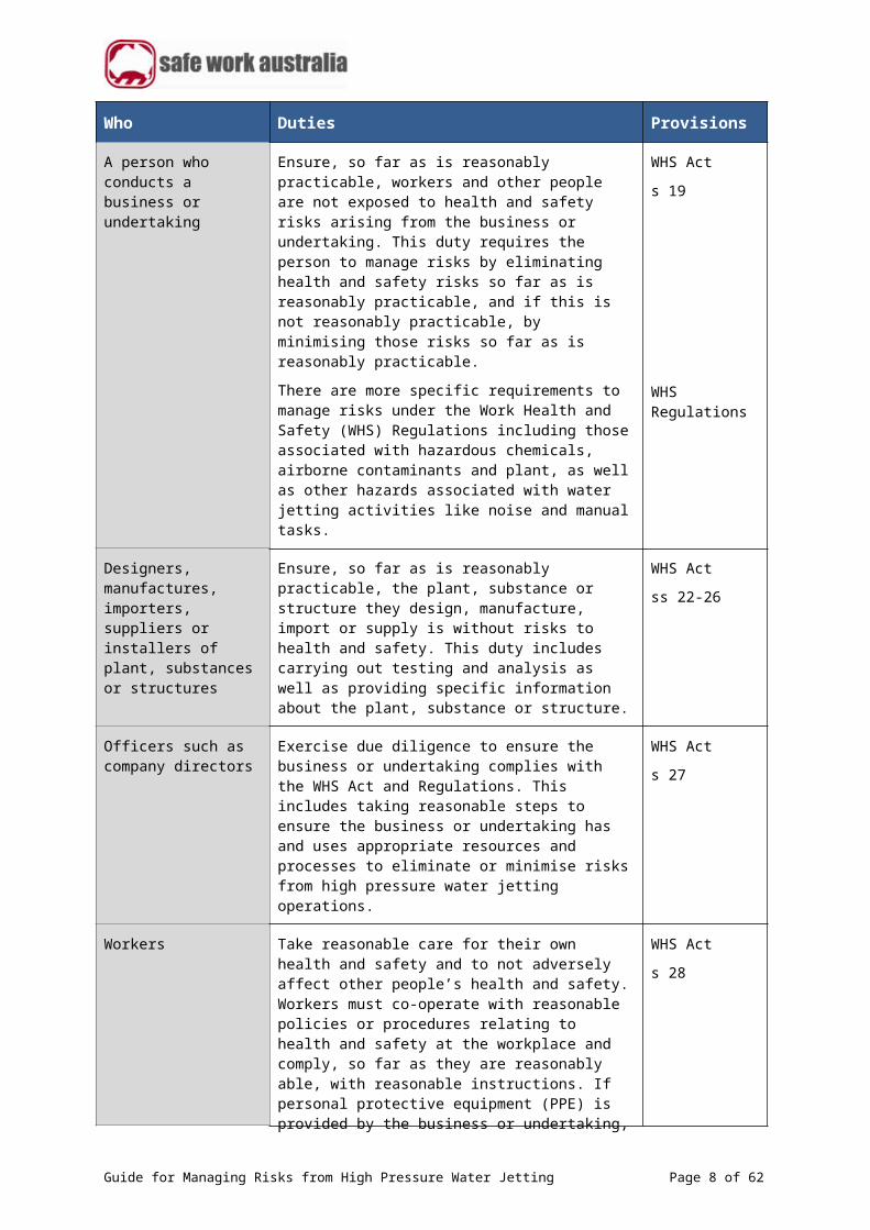
1.2 Who has health and safety duties in relation to water jetting?
Table 1 Duties in relation to water jetting
Who Duties Provisions
A person who conducts a business or undertaking
Ensure, so far as is reasonably practicable, workers and other people are not exposed to health and safety risks arising from the business or undertaking. This duty requires the person to manage risks by eliminating health and safety risks so far as is reasonably practicable, and if this is not reasonably practicable, by minimising those risks so far as is reasonably practicable.
There are more specific requirements to manage risks under the Work Health and Safety (WHS) Regulations including those associated with hazardous chemicals, airborne contaminants and plant, as well as other hazards associated with water jetting activities like noise and manual tasks.
WHS Act
s 19
WHS Regulations
Designers, manufactures, importers, suppliers or installers of plant, substances or structures
Ensure, so far as is reasonably practicable, the plant, substance or structure they design, manufacture, import or supply is without risks to health and safety. This duty includes carrying out testing and analysis as well as providing specific information about the plant, substance or structure.
WHS Act
ss 22-26
Officers such as company directors
Exercise due diligence to ensure the business or undertaking complies with the WHS Act and Regulations. This includes taking reasonable steps to ensure the business or undertaking has and uses appropriate resources and processes to eliminate or minimise risks from high pressure water jetting operations.
WHS Act
s 27
Workers Take reasonable care for their own health and safety and to not adversely affect other people’s health and safety. Workers must co-operate with reasonable policies or procedures relating to health and safety at the workplace and comply, so far as they are reasonably able, with reasonable instructions. If personal protective equipment (PPE) is provided by the business or undertaking, the worker must so far as they are reasonably able, use or wear it in accordance with the information, instruction and training provided.
WHS Act
s 28
Other persons at the workplace, like visitors
Take reasonable care for their own health and safety and must take reasonable care not to adversely affect other people’s health and safety. They must comply, so far as they are reasonably able, with reasonable instructions given by the person conducting the business or undertaking to allow that person to comply with the WHS Act.
WHS Act
s 29
Guide for Managing Risks from High Pressure Water Jetting Page 7 of 46
1.3 What is involved in managing risks associated with high pressure water jetting?
Chapter 2 of this Guide provides guidance on how to manage the risks associated with high pressure water jetting following a systematic process which involves:
identifying hazards – find out what could cause harm in high pressure water jetting operations
assessing risks if necessary – understand the nature of the harm that could be caused by the hazard, how serious the harm could be and the likelihood of it happening
controlling risks – implement the most effective control measures that are reasonably practicable in the circumstances, and
reviewing control measures to ensure they are working as planned.
Further guidance on the risk management process generally is available in the Code of Practice: How to manage work health and safety risks.
Consulting your workers
Section 47: The person conducting a business or undertaking must, so far as is reasonably practicable, consult with workers who carry out work for the business or undertaking who are, or are likely to be, directly affected by a matter relating to work health or safety.
Section 48: If the workers are represented by a health and safety representative, the consultation must involve that representative.
Consultation involves sharing information, giving workers a reasonable opportunity to express views and taking those views into account before making decisions on health and safety matters.
Consultation with workers and their health and safety representatives is required at each step of the risk management process. By drawing on the experience, knowledge and ideas of your workers you are more likely to identify hazards and choose effective control measures.
You should encourage your workers to report hazards and health and safety problems immediately so the risks can be managed before an incident occurs.
Consulting, co-operating and co-ordinating activities with other duty holders
Section 46: If more than one person has a duty in relation to the same matter under this Act, each person with the duty must, so far as is reasonably practicable, consult, co-operate and co-ordinate activities with all other persons who have a duty in relation to the same matter.
There is often more than one business or undertaking involved in high pressure water jetting operations. Each has responsibility for health and safety to the extent they influence and control aspects of the high pressure water jetting activities. In these situations you should share information to find out who is doing what and work together in a co-operative and co-ordinated way so risks are eliminated or minimised so far as is reasonably practicable.
For example, if you engage a contractor to carry out water jetting operations at your workplace you should find out what work processes are being used, identify associated hazards and how the risks will be controlled. This may include jointly conducting a risk assessment for the work and determining the control measures to implement. You should provide contractors with relevant information to help them assess the risks including from hazardous chemicals which may be present in waste generated by the process. After the risk assessment has been conducted it is important for duty holders to co-operate and co-ordinate activities with each other to implement the control measures.
Further guidance on consultation is available in the Code of Practice: Work health and safety consultation, co-operation and co-ordination.
Guide for Managing Risks from High Pressure Water Jetting Page 8 of 46
1.4 Information, training, instruction and supervision
Section 19: A person conducting a business or undertaking must ensure, so far as is reasonably practicable, the provision of any information, training, instruction or supervision that is necessary to protect all persons from risks to their health and safety arising from work carried out as part of the conduct of the business or undertaking.
Regulation 39: A person conducting a business or undertaking must ensure that information, training and instruction provided to a worker is suitable and adequate having regard to:
the nature of the work carried out by the worker
the nature of the risks associated with the work at the time of the information, training and instruction, and
the control measures implemented.
The person must ensure, so far as is reasonably practicable, that the information, training and instruction provided under this regulation is provided in a way that is readily understandable by any person to whom it is provided.
Workers must be trained and have the appropriate skills to carry out a particular task safely.
Training specific to the water jetting operations should be provided to workers by a competent person. Such training should include the following areas:
Guide for Managing Risks from High Pressure Water Jetting Page 9 of 46
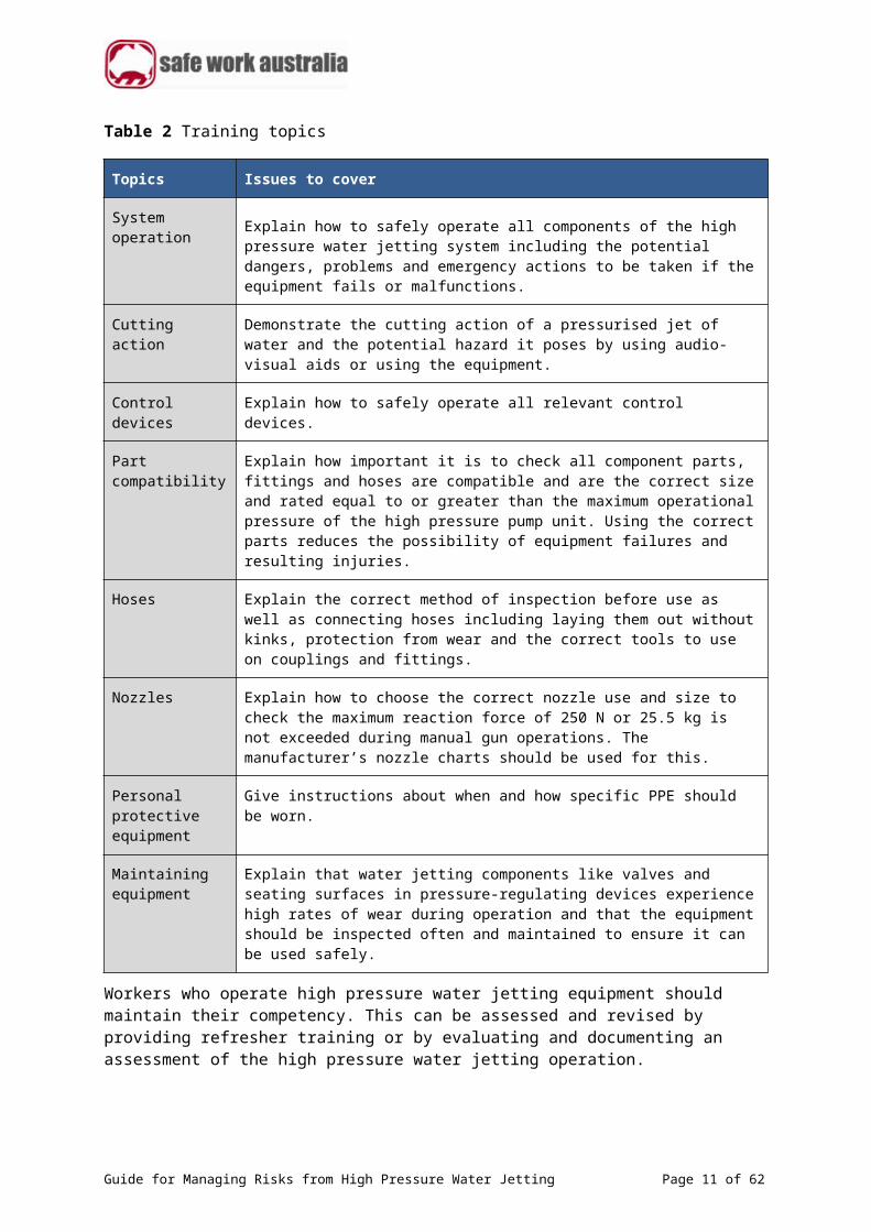
Table 2 Training topics
Topics Issues to cover
System operation Explain how to safely operate all components of the high pressure water jetting system including the potential dangers, problems and emergency actions to be taken if the equipment fails or malfunctions.
Cutting action Demonstrate the cutting action of a pressurised jet of water and the potential hazard it poses by using audio-visual aids or using the equipment.
Control devices Explain how to safely operate all relevant control devices.
Part compatibility Explain how important it is to check all component parts, fittings and hoses are compatible and are the correct size and rated equal to or greater than the maximum operational pressure of the high pressure pump unit. Using the correct parts reduces the possibility of equipment failures and resulting injuries.
Hoses Explain the correct method of inspection before use as well as connecting hoses including laying them out without kinks, protection from wear and the correct tools to use on couplings and fittings.
Nozzles Explain how to choose the correct nozzle use and size to check the maximum reaction force of 250 N or 25.5 kg is not exceeded during manual gun operations. The manufacturer’s nozzle charts should be used for this.
Personal protective equipment
Give instructions about when and how specific PPE should be worn.
Maintaining equipment
Explain that water jetting components like valves and seating surfaces in pressure-regulating devices experience high rates of wear during operation and that the equipment should be inspected often and maintained to ensure it can be used safely.
Workers who operate high pressure water jetting equipment should maintain their competency. This can be assessed and revised by providing refresher training or by evaluating and documenting an assessment of the high pressure water jetting operation.
Guide for Managing Risks from High Pressure Water Jetting Page 10 of 46
2. THE RISK MANAGEMENT PROCESS
2.1 Identifying the hazards
The first step in managing risks associated with high pressure water jetting operations is to identify all hazards that could potentially cause harm to people. These may be identified by:
conducting a walk through assessment of the workplace
observing the work and talking to workers about how water jetting is carried out
inspecting plant and equipment used during high pressure water jetting operations
reading product labels, safety data sheets and manufacturer’s instruction manuals
talking to manufacturers, suppliers, industry associations and health and safety specialists, and
reviewing incident reports.
Some examples of high pressure water jetting hazards include:
cutting and reaction forces from high pressure water jets
flying debris
hazardous chemicals and biological materials
noise, and
water jetting plant and equipment.
2.2 Assessing the risks
A risk assessment is not mandatory for high pressure water jetting operations. However it is required in some situations, for example when working in a confined space. A risk assessment can help:
identify which workers are at risk
determine what sources and processes are causing the risks
identify what kind of control measures should be implemented, and
assess the effectiveness of existing control measures.
The likelihood of each hazard actually causing harm in a specific situation should be assessed. The following questions may help with the assessment:
How often and for how long will exposure to the hazard occur?
If exposed to the hazard will the outcome be severe, moderate or mild?
What is the substrate being blasted?
What are the surface coatings of the items being blasted? For example do they contain lead or other toxic metals?
What are the conditions under which high pressure water jetting operations are being carried out? For example, are they carried out in a confined space?
What are the skills, competence and experience of the operators?
Guide for Managing Risks from High Pressure Water Jetting Page 11 of 46
2.3 Controlling the risks
Some control measures are more effective than others. Control measures can be ranked from the highest level of protection and reliability to the lowest. This ranking is known as the hierarchy of control.
Eliminating the risk
This means removing the hazard or hazardous work practice from the workplace. This is the most effective control measure and must always be considered before anything else.
If eliminating the risk is not reasonably practicable, you must consider using substitution, isolation or engineering controls, or a combination of these control measures to minimise the risk.
Minimising the risk
Substitution
Minimise the risk by substituting or replacing a hazard or hazardous work practice with a safer one.
Isolation
Minimise the risk by isolating or separating the hazard or hazardous work practice from people, for example by installing screens or barriers around the water jetting operations.
Engineering controls
Engineering controls are physical control measures to minimise risk, for example controlling the jet of water mechanically.
If a risk remains, the duty holder must minimise the remaining risk, so far as is reasonably practicable by using:
Administrative controls
Administrative controls should only be considered when other higher order control measures are not reasonably practicable, or to increase protection from the hazard. These are work methods or procedures designed to minimise the exposure to a hazard, for example job rotation and varying tasks to reduce the risks associated with prolonged periods of jetting gun operation and other repetitive manual handling tasks.
Any remaining risk must be minimised, so far as is reasonably practicable, by providing and ensuring the use of:
Personal protective equipment
PPE is the lowest order control measure in the hierarchy of controls. PPE should also only be considered when other higher order control measures are not reasonably practicable or to increase protection from the hazard. Examples of PPE include using safety eyewear, hearing protection, safety helmets, cut-resistant leg protection or reflective, high-visibility clothing.
Combining control measures
In most cases a combination of the control measures will provide the best solution to minimise the risk to the lowest level reasonably practicable. You should check your chosen control measures do not introduce new hazards.
Guide for Managing Risks from High Pressure Water Jetting Page 12 of 46
2.4 Maintaining and reviewing control measures
The control measures implemented to protect health and safety should be regularly reviewed to make sure they are effective including when there is a change at the workplace. If a control measure is not working effectively it must be revised to ensure it is effective to control the risk.
For example, control measures should be reviewed:
when an injury or illness occurs because of a hazard the risk assessment addressed, or failed to consider
before making changes to the nature of the water jetting operations
before introducing new plant or jetting techniques
if new information becomes available to indicate a control measure may no longer be the most effective way to control the risk, and
when there are changes to who carries out the work.
Control measures should be reviewed in consultation with workers and their health and safety representatives. Workers are often able to quickly identify and propose solutions to problems when they occur.
Control measures should be checked by using the same methods as the initial hazard identification and risk assessment. If a hazard is not eliminated or minimised by the chosen control measure, go back through the risk management steps, review the information and make further decisions about risk control.
Guide for Managing Risks from High Pressure Water Jetting Page 13 of 46
3. GENERAL SAFETY RECOMMENDATIONS
The following safety recommendations should be considered when managing the risks to workers from the hazards associated with high pressure water jetting operations.
3.1 Water jetting plant and equipment
Section 21(2): Persons conducting a business or undertaking who have management or control of plant at a workplace must ensure, so far as is reasonably practicable, the plant is without risks to the health and safety of any person.
Section 22(2): Designers of plant must ensure, so far as is reasonably practicable, the plant is designed to be without risks to the health and safety of persons.
When buying water jetting plant and equipment you should check safety features have been incorporated into the design. The following information must be passed on from the designer to the manufacturer and the supplier and then to the end user:
The purpose the plant was designed or manufactured for.
The results of calculations, analysis, testing or examination necessary to ensure the plant is without risks to health and safety.
Any conditions necessary for the safe use of the plant.
A supplier must give this information to each person who receives the plant which may be in the form of a manufacturer’s manual.
Suppliers of new and second-hand high pressure water jetting equipment must ensure, so far as is reasonably practicable, it is without risks to health and safety. For example, it is in safe working order. A supplier must also provide the manufacturer’s safe operating procedures.
A supplier of second-hand high pressure water jetting equipment must ensure, so far as is reasonably practicable, any associated risks are identified. Before the equipment is supplied, ensure the person to whom the equipment is supplied is given written notice of:
the condition of the plant
any faults identified, and
if required, that the plant should not be used until the faults are rectified.
The manufacturer’s safe operating procedures should be followed by anyone carrying out water jetting operations.
General
Water jetting plant, equipment and attachments should only be used in accordance with the manufacturer’s recommendations.
No rigid lance attachment should be used unless it is fitted with a handle and a hold-to-activate device. It should only be used in accordance with the manufacturer’s instructions.
Jetting equipment and attachments should not be modified without the manufacturer’s approval.
Modifications to Class B equipment and developing new systems incorporating Class B equipment should only be carried out by a competent person with relevant engineering skills. Such modifications or developments should be consistent with relevant safety recommendations.
Limits and use
A high pressure water jetting system should not be used unless it:
Guide for Managing Risks from High Pressure Water Jetting Page 14 of 46
has been inspected or serviced in accordance with the manufacturer’s recommendations, and
is free from any fault identified at the last inspection or service which may adversely affect the performance and safe operation of the equipment.
Note: Chapter 4 provides guidance on the inspection, care and maintenance of high pressure water jetting systems.
Safeguards
Anyone using high pressure water jetting equipment should follow these safety recommendations:
Where necessary equipment near jetting operations should be shielded or protected from debris and the ingress of water from operating the jetting equipment.
Any essential electrical installation should meet the required protection levels against the ingress of water vapour or overspray.
People other than the operating team should be kept out of barricaded work areas.
Work activities should be planned to provide safe access to the equipment and item or surface being jetted.
Overhead work should be avoided where possible as this may cause unstable worker positioning and increase the risk of musculoskeletal disorders.
Operators using manually operated jetting systems should be in a safe and well-balanced position before starting jetting operations.
Jetting operations should not be performed from ladders or other surfaces not intended for use by workers as this can lead to loss of control of the jetting equipment.
Operators should check there is no interruption or interference to the release mechanism of hand or foot controls that could stop the equipment operating safely and consistent with the manufacturer’s specifications.
Jetting operations should stop when:
o conditions change or new hazards are introduced
o unauthorised people enter the barricaded area
o recommended safe work practices are not being followed, or
o a malfunction occurs.
Jetting systems should be depressurised and secured when:
o not in use and left unattended, and
o components are being replaced or repairs are being made to the system.
3.2 Medical alert card
Water jetting operators should carry an immediately accessible, waterproof medical alert card issued by the person conducting a business or undertaking (PCBU).
The card should:
outline the possible nature of injuries and post-incident infections that can be caused by high pressure water jetting, and
provide details of immediate first-aid treatment until medical treatment can be arranged.
Guide for Managing Risks from High Pressure Water Jetting Page 15 of 46
4. EQUIPMENT CARE AND MAINTENANCE
High pressure water jetting systems should be maintained by a competent person in accordance with the manufacturer’s recommendations. Records should be kept of service, repairs and maintenance.
4.1 Pump unitThe pump unit should be maintained in accordance with the manufacturer’s instructions. This should include daily pre-operational checks on the following items as applicable:
Engine and drive unit – lubricating oil, water, hydraulic fluid and fuel levels.
Pump unit – lubricating oil, water filters, drive belts, gauges and gearbox oil levels.
Hydraulic hose reel – lubricating oil and fluid levels.
Condition of guards, shields and safety interlocks.
Electric leads and connectors.
4.2 Filters and strainers
Water filters should be checked regularly, depending on the water supply conditions and in accordance with the pump manufacturer’s recommendations.
Water should be cleaned through filters that meet the pump manufacturer’s recommendations. Otherwise this may cause the control mechanisms to malfunction and destroy the equipment, exposing workers to the serious risk of injury.
4.3 Hose assemblies
Hose, couplings, connectors and hose end fittings selected before assembly should be suitable for use with the maximum working pressure of the high pressure water jetting unit to be used.
Before each use, hose assemblies should be visually inspected by a competent person to ensure:
the correct pressure rating and size is selected
there is no apparent structural damage e.g. corroded or broken wires, bulging, kinking or cuts
end fittings are in good condition and of the correct pressure rating for the unit operating pressure, and
hose connections to equipment or other hoses are restrained with braided stockings or are restricted in some other suitable way to stop their movement if the hose end fails.
Hoses with broken wires, deep abrasions, kinking, blisters or bubbles in the outer covering should be identified as ‘defective’ and taken out of service.
End fittings and crimping with cracks, corrosion, damaged threads or other evidence they may not be safe to use should be identified as ‘defective’ and taken out of service.
Testing and verification
Hose assemblies used with Class A water jetting systems should be tested in accordance with the requirements of AS 3791-1991: Hydraulic hose.
Hose assemblies used with Class B water jetting systems should be tested in accordance with AS/NZS 4233 Part 1-1999: High pressure water jetting systems – safe operation and maintenance.
Guide for Managing Risks from High Pressure Water Jetting Page 16 of 46
Records should be kept of all tests. Only those hoses identified as meeting the safe operating performance recommendations should be returned to service.
Hoses should be tested when they:
are new
have been damaged
have been re-ended or repaired, and
have been exposed to adverse operational conditions which may have affected their structural integrity.
Caring for and storing hoses
The service life of a hose assembly is affected by many factors like storage, pressure cycles, temperature, environment, chemical exposure and longitudinal stress.
Table 3 Maximising the service life of hose assemblies
Cause of wear Steps to extend life of hose assemblies
Pressure cycles Hose assemblies should not be unnecessarily subjected to frequent and prolonged periods of high pressure.
Temperature exposure Exposure of hoses to temperatures in excess of the stated rating should be avoided.
Chemical exposure Hose assemblies should not unnecessarily be exposed to chemicals or corrosive substances. Where hose assemblies are exposed to these substances steps should be taken as soon as possible to neutralise their effect.
Longitudinal stress Repetitive and prolonged use of hose assemblies in long-line drain cleaning functions and long vertical drops should be avoided.
Environment exposure Unnecessary exposure to sharp, protruding and abrasive surfaces should be avoided. Where this is not practical, steps should be taken to minimise the damage to hose assemblies.
Storage Where possible, hose assemblies should be stored lying flat in a cool dry area.
Defective hoses should be removed from service and clearly marked and tagged to prevent unintentional use.
4.4 Nozzles Water jetting nozzles are designed to control the direction, velocity, flow rate, pressure, shape and distribution of fluid flow as it exits the nozzle carrier.
Jetting nozzles come in two categories: rear facing nozzles which are used in drain and tube cleaning and forward facing nozzles which are used for general cleaning duties.
Jetting equipment including nozzles should be kept clean and stored safely when not in use.
Nozzles should be inspected before each use for blocked or damaged orifices, damage to threads, cracks or any other structural damage that could adversely affect their safe operation.
Nozzles identified as being defective should be removed from service and repaired or destroyed.
Guide for Managing Risks from High Pressure Water Jetting Page 17 of 46
As well as a pre-start measure, inspecting nozzles regularly during jetting operations can identify wear and damage before this causes an injury.
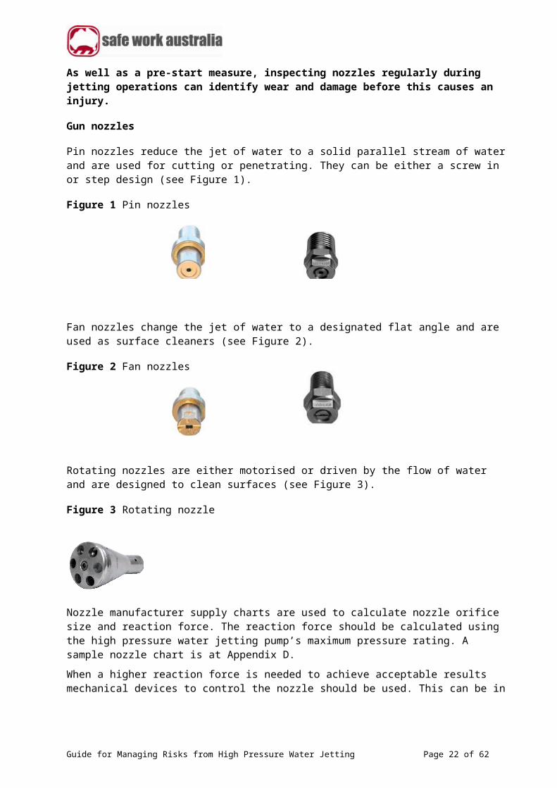
Gun nozzles
Pin nozzles reduce the jet of water to a solid parallel stream of water and are used for cutting or penetrating. They can be either a screw in or step design (see Figure 1).
Figure 1 Pin nozzles
Fan nozzles change the jet of water to a designated flat angle and are used as surface cleaners (see Figure 2).
Figure 2 Fan nozzles
Rotating nozzles are either motorised or driven by the flow of water and are designed to clean surfaces (see Figure 3).
Figure 3 Rotating nozzle
Nozzle manufacturer supply charts are used to calculate nozzle orifice size and reaction force. The reaction force should be calculated using the high pressure water jetting pump’s maximum pressure rating. A sample nozzle chart is at Appendix D.
When a higher reaction force is needed to achieve acceptable results mechanical devices to control the nozzle should be used. This can be in the form of mechanised equipment or engineered structures designed to hold the excess reaction force in all planes.
Pipe cleaning nozzles are designed to clean the internal surfaces of a pipe or tube and can be either spinning or fixed.
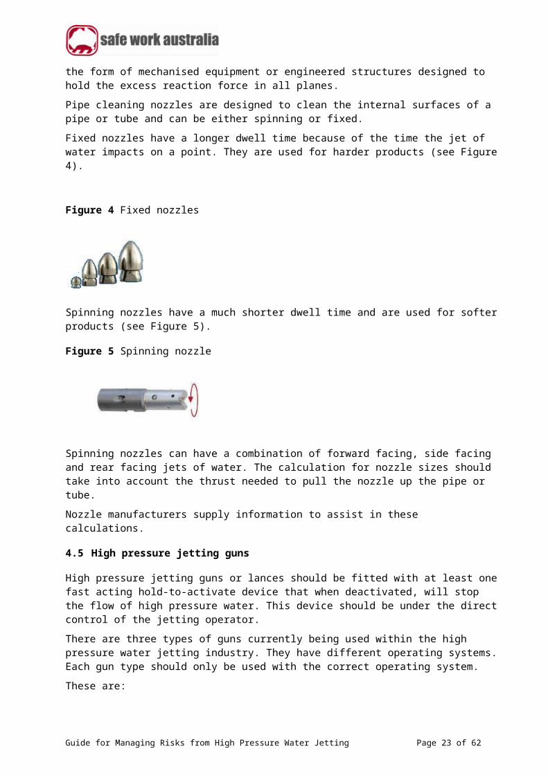
Fixed nozzles have a longer dwell time because of the time the jet of water impacts on a point. They are used for harder products (see Figure 4).
Guide for Managing Risks from High Pressure Water Jetting Page 18 of 46
Figure 4 Fixed nozzles
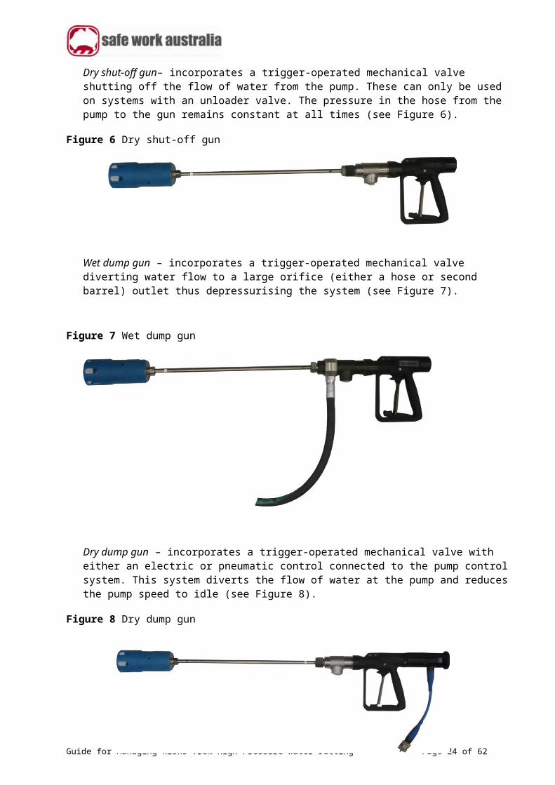
Spinning nozzles have a much shorter dwell time and are used for softer products (see Figure 5).
Figure 5 Spinning nozzle
Spinning nozzles can have a combination of forward facing, side facing and rear facing jets of water. The calculation for nozzle sizes should take into account the thrust needed to pull the nozzle up the pipe or tube.
Nozzle manufacturers supply information to assist in these calculations.
4.5 High pressure jetting guns
High pressure jetting guns or lances should be fitted with at least one fast acting hold-to-activate device that when deactivated, will stop the flow of high pressure water. This device should be under the direct control of the jetting operator.
There are three types of guns currently being used within the high pressure water jetting industry. They have different operating systems. Each gun type should only be used with the correct operating system.
These are:
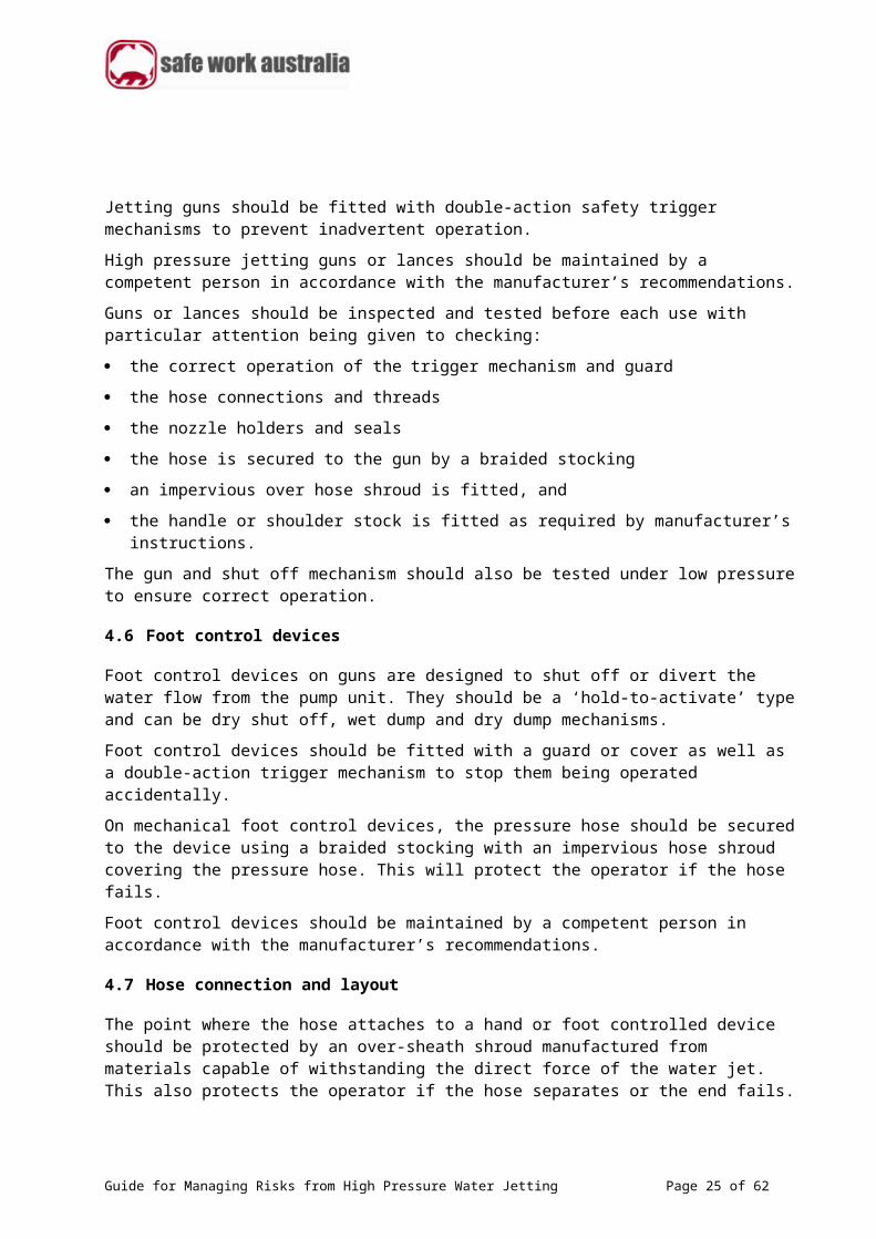
Dry shut-off gun– incorporates a trigger-operated mechanical valve shutting off the flow of water from the pump. These can only be used on systems with an unloader valve. The pressure in the hose from the pump to the gun remains constant at all times (see Figure 6).
Figure 6 Dry shut-off gun
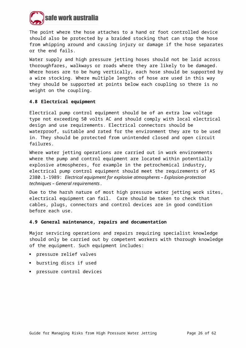
Wet dump gun – incorporates a trigger-operated mechanical valve diverting water flow to a large orifice (either a hose or second barrel) outlet thus depressurising the system (see Figure 7).
Guide for Managing Risks from High Pressure Water Jetting Page 19 of 46
Figure 7 Wet dump gun
Dry dump gun – incorporates a trigger-operated mechanical valve with either an electric or pneumatic control connected to the pump control system. This system diverts the flow of water at the pump and reduces the pump speed to idle (see Figure 8).
Figure 8 Dry dump gun
Jetting guns should be fitted with double-action safety trigger mechanisms to prevent inadvertent operation.
High pressure jetting guns or lances should be maintained by a competent person in accordance with the manufacturer’s recommendations.
Guns or lances should be inspected and tested before each use with particular attention being given to checking:
the correct operation of the trigger mechanism and guard
the hose connections and threads
the nozzle holders and seals
the hose is secured to the gun by a braided stocking
an impervious over hose shroud is fitted, and
the handle or shoulder stock is fitted as required by manufacturer’s instructions.
The gun and shut off mechanism should also be tested under low pressure to ensure correct operation.
Guide for Managing Risks from High Pressure Water Jetting Page 20 of 46
4.6 Foot control devices
Foot control devices on guns are designed to shut off or divert the water flow from the pump unit. They should be a ‘hold-to-activate’ type and can be dry shut off, wet dump and dry dump mechanisms.
Foot control devices should be fitted with a guard or cover as well as a double-action trigger mechanism to stop them being operated accidentally.
On mechanical foot control devices, the pressure hose should be secured to the device using a braided stocking with an impervious hose shroud covering the pressure hose. This will protect the operator if the hose fails.
Foot control devices should be maintained by a competent person in accordance with the manufacturer’s recommendations.
4.7 Hose connection and layout
The point where the hose attaches to a hand or foot controlled device should be protected by an over-sheath shroud manufactured from materials capable of withstanding the direct force of the water jet. This also protects the operator if the hose separates or the end fails.
The point where the hose attaches to a hand or foot controlled device should also be protected by a braided stocking that can stop the hose from whipping around and causing injury or damage if the hose separates or the end fails.
Water supply and high pressure jetting hoses should not be laid across thoroughfares, walkways or roads where they are likely to be damaged. Where hoses are to be hung vertically, each hose should be supported by a wire stocking. Where multiple lengths of hose are used in this way they should be supported at points below each coupling so there is no weight on the coupling.
4.8 Electrical equipment
Electrical pump control equipment should be of an extra low voltage type not exceeding 50 volts AC and should comply with local electrical design and use requirements. Electrical connectors should be waterproof, suitable and rated for the environment they are to be used in. They should be protected from unintended closed and open circuit failures.
Where water jetting operations are carried out in work environments where the pump and control equipment are located within potentially explosive atmospheres, for example in the petrochemical industry, electrical pump control equipment should meet the requirements of AS 2380.1-1989: Electrical equipment for explosive atmospheres – Explosion-protection techniques – General requirements.
Due to the harsh nature of most high pressure water jetting work sites, electrical equipment can fail. Care should be taken to check that cables, plugs, connectors and control devices are in good condition before each use.
4.9 General maintenance, repairs and documentation
Major servicing operations and repairs requiring specialist knowledge should only be carried out by competent workers with thorough knowledge of the equipment. Such equipment includes:
pressure relief valves
bursting discs if used
pressure control devices
Guide for Managing Risks from High Pressure Water Jetting Page 21 of 46
pump control valves or dry shut-off control valves, and
electrical controls and equipment.
Operators of high pressure water jetting systems should not carry out repairs other than simple adjustments to, or replacement of, parts which are specifically listed in the manufacturer’s instructions for use and periodic service. Other repairs or maintenance should be carried out by the manufacturer or other suitably qualified people.
When maintaining or assembling jetting systems the correct sized tools should always be used. Tools of the incorrect size can damage equipment and should not be used.
Maintenance records should be kept for each major piece of equipment. After each inspection or service recommended by the manufacturer the person carrying out the work should record:
the condition of the equipment and hoses
repairs performed
adjustments performed, and
the date when the inspection or work was carried out and the name of the person carrying out the task.
4.10 Marking equipment
Parts or assemblies which should be identified for service, maintenance or application should be permanently marked with enough information to identify the part, its use and performance and in a way which is easy to read.
Pumps
High pressure water jetting systems should be fitted with a permanently mounted name plate which provides the following information:
manufacturer’s name or mark
model designation, serial number and year of manufacture
maximum volume and pressure performance
maximum input speed, and
maximum operating pressure.
Hoses
Hoses should be marked with the following information:
manufacturers identification
date of manufacture, and
maximum operating pressure.
Adaptors and end fittings
Adaptors and end fittings should be marked so the manufacturer’s identification and maximum operating pressure can be identified.
Guide for Managing Risks from High Pressure Water Jetting Page 22 of 46
Hose assemblies
Hose assemblies should be marked so the following information can be clearly identified:
The assembler.
Date of assembly.
Date of testing.
Maximum operating pressure.
Re-ended and retested hoses
Hose assemblies which have been re-ended or retested should be marked so the following information can be identified:
The organisation performing the work.
The organisation performing the retesting.
Date of testing.
Reference to the test reports.
Guide for Managing Risks from High Pressure Water Jetting Page 23 of 46
5. PERSONAL PROTECTIVE EQUIPMENT
Regulation 44: If personal protective equipment is to be used to minimise a risk to health and safety in relation to work at a workplace in accordance with regulation 36, the person conducting a business or undertaking who directs the carrying out of work must provide the personal protective equipment to workers at the workplace, unless the personal protective equipment has been provided by another person conducting a business or undertaking.
The person conducting the business or undertaking who directs the carrying out of work must ensure the equipment is:
selected to minimise risk to health and safety
suitable having regard to the nature of the work and any hazard associated with the work
a suitable size and fit and reasonably comfortable for the worker who is to use or wear it
maintained, repaired or replaced so that it continues to minimise risk to the worker who uses it
clean, hygienic and in good working order, and
used or worn by the worker, so far as is reasonably practicable.
Regulation 45: The person conducting a business or undertaking who directs the carrying out of work must ensure, so far as is reasonably practicable, that personal protective equipment to be used or worn by any person other than a worker at the workplace is capable of minimising risk to the person's health and safety and the person uses or wears the equipment.
Regulation 46: The worker must, so far as the worker is reasonably able, use or wear the equipment in accordance with any information, training or reasonable instruction given by the person conducting the business or undertaking.
The worker must not intentionally misuse or damage the equipment.
As high pressure water jetting is very hazardous, suitable PPE should always be worn regardless of other control measures in place.
5.1 Head protection
Where required, head protection complying with AS/NZS 1801:1997: Occupational protective helmets should be worn.
5.2 Eye protection
Eye protection suitable for the task, of good fit on the worker and complying with AS/NZS 1337:2010 (Series): Personal eye protection should always be worn when the worker is near jetting operations. The worker in direct control of the flow of water should as a minimum, wear safety glasses and a face shield complying with AS/NZS 1337.
Where liquids which can cause eye damage are being used at the workplace it may be necessary to use a combination of a face shield visor and goggles or a full hood with shield.
5.3 Leg and body protection
Workers should wear waterproof protective clothing complying with AS 3765.1-1990: Clothing for protection against hazardous chemicals – Protection against general or specific chemicals or AS 3765.2-1990: Clothing for protection against hazardous chemicals – Limited protection against specific chemicals.
Guide for Managing Risks from High Pressure Water Jetting Page 24 of 46
Leg and body armour manufactured from materials capable of withstanding the direct force of the water jet should be used by water jetting operators where there is risk of injury.
Liquid or chemical-resistant suits should be worn where a risk assessment indicates these are required.
5.4 Hand protection
Hand protection complying with the recommendations of AS/NZS 2161.2:2005: Occupational protective gloves - General requirements, AS/NZS 2161.3:2005: Occupational protective gloves - Protection against mechanical risks or AS/NZS 2161.5:1998: Occupational protective gloves - Protection against cold, should be worn where a risk assessment indicates this is required.
5.5 Foot and lower leg protection
Workers should wear protective footwear complying with AS/NZS 2210.3:2009: Occupational protective footwear – Specification for safety footwear. A foot and lower leg guard or shield made from material capable of withstanding the direct force of the water jet should be used where there is a risk of foot or leg injury.
Further guidance on the selection of footwear is in AS/NZS 2210.1:2010: Safety, protective and occupational footwear - Guide to selection, care and use.
5.6 Personal hearing protectors
Where noise cannot be eliminated or minimised, so far as is reasonably practicable, personal hearing protectors as well as instruction and training in their use should be provided.
Hearing protectors should be selected in accordance with AS/NZS 1269.3:2005: Occupational noise management – hearing protector program and tested in accordance with AS/NZS 1270:2002: Acoustics - hearing protectors.
5.7 Respiratory protection
Workers involved in high pressure water jetting operations should wear respiratory protection where there is an assessed risk of injury that can be prevented by such equipment. Respiratory protection should only be worn by workers who have been trained in its correct use.
A respiratory protection program should be implemented where there is evidence it could prevent injury or disease.
AS/NZS 1715:2009: Selection, use and maintenance of respiratory protective equipment provides guidance on the implementation of respiratory protection programs.
Guide for Managing Risks from High Pressure Water Jetting Page 25 of 46
6. PLANNING AND PRE-OPERATIONAL PROCEDURES
6.1 General
Assessing and planning each job is important. This ensures high pressure water jetting is carried out in a way that is without risks to health and safety.
Planning usually starts with initial customer liaison and a job or site inspection. People planning the work and people familiar with the work environment and the item or material to be jetted, should meet with the workers who will be carrying out the work to identify and discuss:
potential hazards of the work area
control measures to be implemented
potential environmental problems
safety standards, and
emergency procedures.
Based on this information, the job can then be planned.
Further information on consulting, co-operating and co-ordinating activities with other duty holders is in section 1.3.
As a minimum the planning process should include:
the number of workers and any special skills, qualifications or training required - over and above the safe use of high pressure water jetting e.g. an elevated work platform licence
isolation procedures including locking and tagging
equipment required including PPE
barricading and signage requirements
notifying other workers nearby
providing safe work instructions for workers
calculations to ensure when manual gun operations take place the reaction force is equal to or below the maximum reaction force of 250 N or 25.5 kg, and
the crew completing a pre-start hazard assessment before starting jetting operations.
6.2 Asbestos
High pressure water jetting must not be carried out on asbestos or asbestos containing material.
Regulation 446: A person conducting a business or undertaking must not use, or direct or allow a worker to use, high-pressure water spray on asbestos or asbestos containing material.
Asbestos can release airborne fibres whenever it is disturbed. Inhaling these fibres is a significant health risk. Asbestos has been used in products including:
certain textured coatings and paints
roofing materials
vinyl or thermoplastic floor tiles, profiled sheets used on roofs and walls and flat sheets in flashings
imitation brick cladding, and
plaster patching compounds.
Guide for Managing Risks from High Pressure Water Jetting Page 26 of 46
The WHS Regulations contain specific requirements on asbestos and asbestos-containing material.
It can be difficult to identify whether asbestos is used in a product just by looking at it. Having a sample of the suspected material analysed will confirm whether asbestos is present or not. Sampling can be hazardous and must only be done by a competent person. Samples must only be analysed by a National Association of Testing Authorities accredited laboratory or a laboratory approved by the regulator or operated by the regulator.
Further information on asbestos is available in the Code of Practice: How to safely remove asbestos and the Code of Practice: How to manage and control asbestos in the workplace.
6.3 Training and operator competency
People who use high pressure water jets and equipment should be competent to carry out the task they are requested to complete. This means they should be trained or instructed using a structured competency-based process.
Operators should also undergo competency-based training on a specific task or equipment they work on. See section 1.4.
6.4 Safe work instructions
Safe work instructions should be developed for using high pressure water jetting units and should be used with a pre-start hazard identification system.
6.5 Pre-start checks and hazard assessment
Pre-start checks should be done before every operation. These can be in the form of checklists which should be completed in consultation with all operators involved in the job. A basic checklist should cover:
the type of job
high pressure pump checks including mechanical and safety devices
isolation procedures including locking and tagging
hose checks including where required the currency of hose tags or certificates
barricades and signs
workers required
special equipment used, and
special work permits.
A pre-start hazard identification and assessment should also be carried out on each job. Safe work instructions manage the repetitive elements of a task but they are not effective when there are changes in the work environment.
An example of a pre-service and operational checklist is at Appendix C.
6.6 Work areas, barricades and signs
A safe area should be established around the planned jetting operations. The limits of this area should be clearly defined by using a physical barrier. This area is known as the safety zone.
Guide for Managing Risks from High Pressure Water Jetting Page 27 of 46
Where jetting operations are not shielded by physical barriers, for example inside a vessel, the perimeter of the defined area should be outside the effective range of the jet of high pressure water. Barriers should also stop people coming into contact with other hazards associated with the jetting operation like flying scale or debris falling from above.
Where work is carried out on public roads, work areas should also comply with AS 1742.3-2009: Manual of uniform traffic control devices - Traffic control for works on roads.
All high pressure water jetting equipment including the jetting unit should be located within the safety zone. Entry into the safety zone should be restricted to authorised people through a designated safe entry point.
The safe entry point should be established by the work crew as part of the pre-start hazard identification process and should be identified by a sign with the words “ENTRY BY AUTHORISED PERSONS ONLY”. The safe entry point should be located where it can be monitored by a safety observer while they also carry out their primary role of observing the work area and jetting operator without distraction.
Where it is not possible to locate a safe entry point that is monitored by a safety observer, the work area should be treated as a total exclusion zone and access restricted to only those workers actually carrying out the work. This may be necessary for situations where the observer does not have a clear view of people approaching the work area.
When high pressure water jetting equipment is being operated, signs indicating “DANGER – HIGH PRESSURE WATER JETTING EQUIPMENT IN USE” should be displayed where they are clearly visible to people approaching the area and those near the area where the equipment is being used.
Signs should also be used to warn people they are approaching a hazardous area.
Further guidance on signs is in AS 1319-1994: Safety signs for the occupational environment.
6.7 Equipment placement
The correct placement or positioning of high pressure water jetting plant and equipment in the workplace is important for health and safety and efficient operations. The pump unit should be placed as close as possible to the work site to reduce the amount of hose used and to reduce the area covered by the operation.
Check that plant and equipment placement does not become a hazard and critical access ways are left unobstructed. Hoses should be arranged to effectively minimise potential tripping hazards. The pump unit should not be placed where it can be contaminated by debris from the jetting operation.
Guide for Managing Risks from High Pressure Water Jetting Page 28 of 46
7. OPERATIONAL PROCEDURES
7.1 Shutoff devices
Every high pressure water jetting operation should include at least two ways of stopping the flow of high pressure water. One of these shutoffs should be controlled by the nozzle operator and should be a fast acting self-actuating hold-to-activate shutoff device. The other shutoff should be an emergency stop device controlled by the safety observer.
7.2 System compatibility
Equipment used including guns, foot control devices, hoses and nozzles during water jetting operations should be suitable for use with greater than or equal to the maximum operating pressure of the high pressure pump.
The safety relief device, for example the safety valve or burst disc should be set at a minimum of 10 percent over the maximum operating pressure of the high pressure pump and in accordance with the manufacturer’s recommendations.
7.3 Operational roles and communication
Each worker within the work team should have a defined role, for example the nozzle operator or safety observer. Where possible, workers should swap roles throughout the course of the jetting operations to avoid fatigue and to keep alert.
Effective communication between members of the work team during jetting operations is very important. A mechanism, for example radio headphones which allow the nozzle operator to convey their requirements to the pump operator or observer will make the jetting operations safer and more efficient.
The most common way of communicating is by using hand signals. If hand signals are used, workers should agree on a set of signals before starting jetting operations. Every worker should understand and be alert to the signals at all times.
Hand signals should not be used as the communication method where the nozzle operator requires two hands to safely hold the device. In these circumstances alternative communication methods should be provided.
Further information on hand signals for high pressure water jetting operations are in Appendix E.
7.4 Gun work
Using a hand held gun for jetting operations increases the risk of the high pressure water jet coming into contact with and injuring the operator. Where eliminating the use of a hand held gun for jetting operations is not possible, using one or a combination of the following control measures may minimise the risk, so far as reasonably practicable:
a gun with a barrel or lance length* that ensures the nozzle strikes the ground before the operator can inadvertently direct it onto their feet or legs
dual hold-to-activate devices on the gun
foot and lower leg guards or shields manufactured from material capable of withstanding the direct force of the jet, and
a body harness that prevents the gun being aimed at the operator.
Guide for Managing Risks from High Pressure Water Jetting Page 29 of 46
Note: In some circumstances, for example industrial rope access work or working in confined spaces, it may be necessary to use a much shorter barrel on the gun. Extreme caution should be exercised by the gun operator and the other team members to ensure risks likely to affect the safety of workers operating the equipment or working nearby are minimised, so far as is reasonably practicable.
Where possible the operator should be allowed to experience the reaction force of the high pressure water jet progressively until the required operating pressure is reached. The operator should be able to stand comfortably and unsupported without straining while operating the gun.
The reaction force along the axis of the gun barrel should be calculated for an average operator to retain control of the gun safely and comfortably. The lowest pressure suitable for the work should be used. A maximum reaction force of 250 N or 25.5 kg is recommended.
When a higher reaction force is needed to achieve acceptable results mechanical devices to control the nozzle should be used, for example gimbals and remote controlled machinery.
Figure 9 Nozzle clamp (gimbal)
Critical elements to consider when carrying out gun work include ensuring:
a dedicated safety observer in control of an emergency shut off device is part of the work team, whose primary concern is the welfare of the worker operating the gun
the work area is free of trip or fall hazards
the gun is tested at low pressure and at working pressure before each use
operating pressure is gradually increased so the operator becomes accustomed to the reaction force, and
people not actively involved in the jetting operation remain outside the safety zone.
7.5 Pipe cleaning
Pipe cleaning is another common use for high pressure water jetting. However the process is inherently hazardous because the high pressure nozzle is attached to a flexible hose which reduces the operator’s control of it.
Operators should check pipe cleaning jobs are set up so the nozzle cannot physically come out of the pipe when it is under pressure. An anti-withdrawal device that is mechanically held to the end of the pipe should be used. This device has an opening in it through which the hose is fed and will stop the hose or nozzle being ejected inadvertently or by hydraulic force.
Hoses should be clearly marked at a suitable distance from the nozzle to indicate the location of the nozzle as it is withdrawn from the pipe or tube.
A foot control hold-to-activate device e.g. a foot pedal—should be used on every pipe cleaning job. This eliminates relying on the operator to physically shut down the high pressure pump in the event of an incident.
Guide for Managing Risks from High Pressure Water Jetting Page 30 of 46
During manual pipe cleaning or lancing operations, the entrance to the line or pipe should not be cleaned with a lance fitted with a retro (back) jet. Where a retro jet is used for pipe cleaning or lancing, the nozzle operator should be provided with suitable guards and PPE to shield them from the water and debris.
The clearance between the outside diameter of each of the hose, lance or nozzle assembly and the inside wall of the item being cleaned should be sufficient to allow the washout of water and debris. Where the diameter of the nozzle and hose assembly exceeds two-thirds of the pipe being cleaned, extra care is required to minimise the risk of the nozzle and debris forming a hydraulic piston which may be forced out under pressure towards the operator.
Where the length of the nozzle and rigid hose coupling and bend radius of the hose is less than the internal diameter of the pipe, a length of rigid pipe (a starter bar) should be used to extend that distance to a length of at least the pipe internal diameter.
If the use of a starter bar is not feasible, a suitable safety shield (able to withstand a direct and sustained blast of the jet) should be provided to protect the operator should the nozzle turn through 180 degrees or double back towards the operator.
When cleaning vertical pipelines that are blocked, it is almost always necessary to clean the pipe from the bottom to allow the scale to fall out and stop the hose from becoming jammed. This process introduces the hazard of the hose falling out of the pipe either under pressure or as pressure is applied.
One method of controlling this risk is to use an anti-withdrawal device attached to the end of the pipe with an opening in it through which the hose is fed. The nozzle is attached after the hose is passed through the opening, with the diameter of the opening being smaller than the diameter of the nozzle. This prevents the nozzle from falling any further than the end of the pipe.
7.6 Heat exchanger cleaning
Heat exchangers can be de-scaled manually or by using automated or semi-automated equipment. Where deposits are soft, for example oil deposits, manual cleaning techniques are usually used.
Manual cleaning is usually carried out by at least two operators. One worker operates the hose or flexible lance and controls the water flow via a foot control device, while the other worker acts as an observer and controls an emergency shutdown mechanism and other shut off devices where applicable.
The most significant risks from cleaning a heat exchanger are:
the nozzle exiting the tube being cleaned while still under pressure
the tube becoming pressurised and forcing the nozzle out at the operator end
the tube becoming pressurised and ejecting a plug of scale or steel blocking a faulty tube, and
the nozzle and hose assembly being damaged when exiting the tube.
Possible control measures for these hazards include:
using chemicals to clean tubes
using mechanical or automated lance handling equipment
installing mechanical shields over the end of the tube bundle opposite to the end being worked on
limiting the distance the hose can enter a tube
using nozzle extensions preventing it and hose crimps from fouling on the tube face when being pulled back into the tube, and
Guide for Managing Risks from High Pressure Water Jetting Page 31 of 46
using anti-withdrawal devices to prevent inadvertent or hydraulic force ejection of the flexible lance and nozzle.
This work requires specialised skills. Each person who carries out this task should have received specific training and instruction in how to operate the equipment used and how to perform the task safely by a person who is competent in this field.
7.7 Surface preparation
Surface preparation work generally uses ultra-high pressure water jetting equipment. This means very high pressures in excess of 2,500 bar and low water flows are used. As a result the effective range of the water jets is comparatively lower than those used for other general cleaning and de-scaling activities. However the cutting efficiency of the jets at close range is significantly higher and increases the potential for injury.
Where handguns are used for surface preparation work the control measures listed in the section on ‘gun work’ should be considered.
Cleanliness and care of ultra-high pressure water jetting equipment is essential. Water filters should be regularly checked and cleaned or replaced. Hoses and high pressure fittings should be taped or covered when not in use to stop the ingress of dirt and other foreign material. Systems should be thoroughly flushed before each use to ensure nozzles are not damaged or blocked by foreign particles.
7.8 Vessel cleaning
An operator working inside a vessel while cleaning it using high pressure water jetting is a high risk activity. The need for an operator to enter a vessel during cleaning should be eliminated so far as is reasonable practicable.
Tank cleaning heads can be used instead. These can be mounted in a variety of ways, for example by being hung from cables or mounted on a rigid fixture. The most important aspect of their operation is to check the arms are not bent and the nozzles are balanced and in good condition. If there are problems in either of these areas, the reaction forces on the head will be unbalanced and injury or damage to the equipment could result. This will be obvious if only the hose or cable supports the tank cleaning head as it is likely to swing about uncontrolled inside the vessel.
7.9 Drain cleaning
Although drain cleaning operations usually operate at considerably lower pressures than needed for most high pressure water cleaning jobs, they share many of the same hazards and operational aspects of high pressure water. Although pressures used may be lower, the power available at the nozzle is comparable with high pressure pumps so it is just as hazardous.
Most drain cleaning is carried out using a truck mounted pressure pump with or without a suction unit to remove the debris. Drain cleaners operate at pressures of around 150 to 210 bar and flow rates of 250 to 300 litres per minute.
Most drain cleaners are controlled by a remote control pendant that allows the operator to move about the rear of the truck and have total control of the operation at all times.
The risks created by other hazards should be assessed when choosing a suitable number of workers to safely carry out the operations-(see section 1.1). Drain cleaning units use positive displacement pumps similar to high pressure units. The majority of other equipment used in this application is the same as the equipment used for high pressure applications and should be subject to the same maintenance and safety procedures.
Guide for Managing Risks from High Pressure Water Jetting Page 32 of 46
8. HAZARDOUS WASTE MATERIAL
8.1 Hazardous waste
Water jetting produces debris which may contain hazardous materials including chemicals like heavy metals and biological waste which create risks to health and safety.
Note: This material should not contain asbestos as the WHS Regulations prohibit the use of high pressure water jetting on asbestos or asbestos containing material.
A product safety data sheet should be obtained before starting water jetting operations to identify if hazardous materials are present in the substrate or coating being jetted.
The risks arising from potential exposure to hazardous waste material should be identified, assessed and controlled in accordance with the requirements of the WHS Regulations.
Regulation 49: A person conducting a business or undertaking at a workplace must ensure that no person at the workplace is exposed to a substance or mixture in an airborne concentration that exceeds the exposure standard for the substance or mixture.
Safe working procedures should consider how to eliminate or minimise exposure to this material during water jetting operations. PPE and facilities suitable for the hazardous materials known or suspected to be present in waste generated from water jetting operations should be provided.
Further guidance on hazardous chemicals can be found in the Code of Practice: Managing risks of hazardous chemicals in the workplace.
8.2 Hazardous waste disposal
The risk of exposure to hazardous waste material may also arise when loading, transporting and unloading debris for disposal.
The person conducting the business or undertaking should manage the risk to health and safety arising from the disposal of waste material and ensure the material is handled and disposed of in accordance with work health and safety and environmental protection requirements.
Guide for Managing Risks from High Pressure Water Jetting Page 33 of 46
APPENDIX A – DEFINITIONS
Anti-withdrawal device means a device designed to stop a flexible lance from ejecting or being pulled from a tube or pipe during the lancing operation.
Bar litres per minute is a commonly used measure of the energy produced by a high pressure water jetting system expressed as a pressure, volume value per unit of time. See Appendix B – Pressure flow diagram.
Bursting disc means a safety device designed to rupture and discharge the fluid to stop a safe pre-determined pressure being exceeded.
Class A system means a high pressure water jetting system producing a maximum energy, measured in pressure volume units per minute—for example bar litres per minute—between 800 bar litres per minute and 5600 bar litres per minute. See Appendix B – Pressure flow diagram.
Class B system means a high pressure water jetting system producing a maximum energy, measured in pressure volume units per minute—for example bar litres per minute—exceeding 5600 bar litres per minute. See Appendix B – Pressure flow diagram.
Competent person means a person who has acquired through training, qualification or experience the knowledge and skills to carry out the task.
Dump valve system means an operator controlled system that opens a free flow path for the water (either to ground or recycled), reducing the system pressure to a safe level without shutting off the flow to the nozzle.
Extra low voltage means 50 volts AC as defined in AS/NZS 3000:2007: Electrical installations.
Foot control device means a control device arranged for actuation by an operator’s foot either in place of or in addition to another form of control.
High pressure water jetting system means a water delivery system consisting of an energy source, for example electric motor or internal combustion engine, pump, control mechanism, hoses and pipes, nozzles and various other attachments and components necessary for the equipment to function as a system. The function of the system is to increase the velocity of the liquids at the point of application. Solid particles or extra chemicals may also be introduced but the exit in all cases will be a free stream.
Hose assembly means a hose with couplings or end fittings attached in accordance with the hose manufacturer’s recommendations.
Jetting gun means a portable combination of the operator’s control valve, lance and nozzle, normally resembling a gun in arrangement.
LancesFlexible lance means a flexible hose used to feed a nozzle through pipes or tubes.
Rigid lance means a rigid tube used to extend the nozzle from the end of the hose or flexible lance.
Lancing (rigid or flexible) means an application where a lance and nozzle combination is inserted into and retracted from the interior of a pipe or tubular product.
Mechanical device means a device engineered and manufactured to restrain a nozzle carrier, or lance where reaction forces exceed 250 N or 25.5 kg. These devices can either be manual or automated.
Nozzle means a device with one or more openings where the fluid discharges from the system. The nozzle restricts the area of flow of the fluid accelerating the water to the required velocity and shaping it to the required flow pattern and distribution for a particular use. Combinations of forward and backward nozzles are often used to balance the thrust.
Guide for Managing Risks from High Pressure Water Jetting Page 34 of 46
Operator means a person who has been trained and has demonstrated competence to perform a water jetting task without supervision.
Reaction force means the force created by water moving as it leaves the nozzle. The force acts in the opposite direction to moving water.
Relief valve means a valve which automatically opens to discharge fluid to relieve pressure.
Safety observer means a member of the work team assigned with the following tasks:
observing the jetting operations and barricaded area
shutting down the system in an emergency or if the system malfunctions
controlling or communicating to the controlling operator the system pressure as requested by the jetting operator, and
controlling access of people into the safety zone.
Starter bar means a rigid piece of pipe fixed to a nozzle that prevents reversing of the nozzle in the line.
Water jet means a jet stream of water produced from the individual nozzle orifice. The shape of the jet is determined by the form of the orifice while the speed at which it travels is determined by the orifice design, orifice area and pressure.
Guide for Managing Risks from High Pressure Water Jetting Page 35 of 46
APPENDIX B – PRESSURE FLOW DIAGRAM
Figure 10 shows a way to calculate and compare the output capability (pressure volume combination) and classify high pressure water jetting systems.
The output of jetting systems is normally measured in bar litres per minute.
Figure 10 Pressure flow chart
Guide for Managing Risks from High Pressure Water Jetting Page 36 of 46
APPENDIX C – EXAMPLE OF A PRE-SERVICE AND OPERATIONAL CHECKLIST
Date:…………………………..
Location:………………………
Equipment/Item being cleaned:
1. Is the work area including the other end of the unit being cleaned clearly defined?
2. Are warning signs posted?
3. Have precautions been taken to protect electrical equipment?
4. Is there a risk to workers or possible damage to equipment from things like the release of chemicals, hot or flammable liquids, gases, drifting mist or other materials?
5. Have workers nearby been told about the intention to carry out water jetting operations?
6. Are components, for example fittings, hoses, guns and foot pedals of the correct pressure rating?
7. Are the hoses of the correct pressure rating?
8. Are hoses in safe operating condition?
9. Are fittings in safe operating condition?
10. Are hoses and lines protected from accidental damage?
11. Are nozzles free from blockages and in safe operating condition?
12. Have steps been taken to prevent inadvertent nozzle reversal or ejecting accidentally?
13. Is the filter on the pump water supply suction clean and in safe operating condition?
14. Is there a suitable cool and clean water supply?
15. Have workers been provided with PPE appropriate for this job?
16. Have workers received the correct level of training for the job?
17. Are workers competent to carry out this work?
18. Has the complete hose run been flushed and air removed from the system?
19. Has the hook-up including pipes, hoses and connections been pressure tested with water at the maximum operating pressure?
20. Are control systems operating correctly?
21. Is the location of emergency medical aid known by workers?
22. Has an effective communication system been put in place for the job?
23. Have the emergency stops been tested?
24. Has the reaction force been calculated to ensure that it is under 250N (25.5kgs) for hand held gun work?
Guide for Managing Risks from High Pressure Water Jetting Page 37 of 46
APPENDIX D – EXAMPLE OF A NOZZLE CHART USED TO CALCULATE REACTION FORCE
A nozzle chart lets operators calculate reaction force. Reaction force should be calculated using the high pressure water jetting pump’s maximum pressure rating.
When using the chart, operators must first determine the maximum operating pressure of the pump. This is listed across the top of the chart. The required flow rate is then selected. By matching the pressure and flow, the chart then gives you a reaction force in Newtons that is appropriate to the selected nozzle size.
Nozzle Ø mm
Part-No.
Operating pressure - bar
200 300 400 500 600 700 750 800 900 1000 1100 1200 1300 1400 1500
Flow rate – L/min
Recoil force in jetting direction /(N)*
0,15 0,2
1
0,2
1
0,3
1
0,3
2
0,3
2
0,4
2
0,4
2
0,4
3
0,4
3
0,4
3
0,5
4
0,5
4
0,5
4
0,5
5
0,5
5
0,20 0,3
1
0,4
2
0,5
2
0,5
3
0,6
3
0,6
4
0,7
4
0,7
5
0,7
5
0,8
6
0,8
6
0,8
7
0,9
7
0,9
8
0,9
9
0,25 0,5
2
0,7
3
0,8
4
0,9
4
0,9
5
1,0
6
1,0
7
1,1
7
1,1
8
1,2
9
1,3
10
1,3
11
1,4
12
1,4
13
1,5
13
0,30 0,8
3
1,0
4
1,1
5
1,2
6
1,4
8
1,5
9
1,5
10
1,6
10
1,7
12
1,7
13
1,8
14
1,9
15
2,0
17
2,1
18
2,1
19
0,35 1,1
4
1,3
5
1,5
7
1,7
9
1,8
11
2,0
12
2,1
13
2,1
14
2,3
16
2,4
18
2,5
19
2,6
21
2,7
23
2,8
25
2,9
26
0,40 1,4
5
1,7
7
2,0
9
2,2
11
2,4
14
2,6
26
2,7
17
2,8
18
2,9
21
3,1
23
3,3
25
3,4
27
3,5
30
3,7
32
3,8
34
0,45 1,8
6
2,2
9
2,5
12
2,8
14
3,0
17
3,3
20
3,4
22
3,5
23
3,7
26
3,9
29
4,1
32
4,3
35
4,5
38
4,6
41
4,8
43
Guide for Managing Risks from High Pressure Water Jetting Page 38 of 46
Nozzle Ø mm
Part-No.
Operating pressure - bar
200 300 400 500 600 700 750 800 900 1000 1100 1200 1300 1400 1500
Flow rate – L/min
Recoil force in jetting direction /(N)*
0,50 2,2
7
2,7
11
3,1
14
3,4
18
3,8
21
4,1
25
4,2
27
4,3
29
4,6
32
4,8
36
5,1
39
5,3
43
5,5
47
5,7
50
5,9
54
0,55 2,6
9
3,2
13
3,7
17
4,1
22
4,5
26
4,9
30
5,1
32
5,2
35
5,6
39
5,9
43
6,2
48
6,4
52
6,7
56
6,9
61
7,2
65
0,60 3,1
10
3,8
15
4,4
21
4,9
26
5,4
31
5,8
36
6,0
39
6,2
41
6,6
46
7,0
52
7,3
57
7,6
62
8,0
67
8,3
72
8,5
77
0,65 3,7
12
4,5
18
5,2
24
5,8
30
6,3
36
6,9
42
7,1
45
7,3
48
7,8
54
8,2
60
8,6
67
9,0
73
9,3
79
9,7
85
10,0
91
Nozzle Ø mm
Part-No.
Operating pressure - bar
200 300 400 500 600 700 750 800 900 1000 1100 1200 1300 1400 1500
Flow rate – L/min
Recoil force in jetting direction /(N)*
0,70 4,2
14
5,2
21
6,0
28
6,7
35
7,4
42
7,9
49
8,2
53
8,5
56
9,0
63
9,5
70
10,0
77
10,4
84
10,8
91
11,2
98
11,6
105
0,75 4,9
16
6,0
24
6,9
32
7,7
40
8,4
48
9,1
56
9,4
60
9,8
64
10,3
72
10,9
81
11,4
89
11,9
97
12,4
105
12,9
113
13,4
121
0,80 5,5
18
6,8
27
7,8
37
8,8
46
9,6
55
10,4
64
10,7
69
11,1
73
11,8
82
12,4
92
13,0
101
13,6
110
14,1
119
14,7
128
15,2
137
Guide for Managing Risks from High Pressure Water Jetting Page 39 of 46
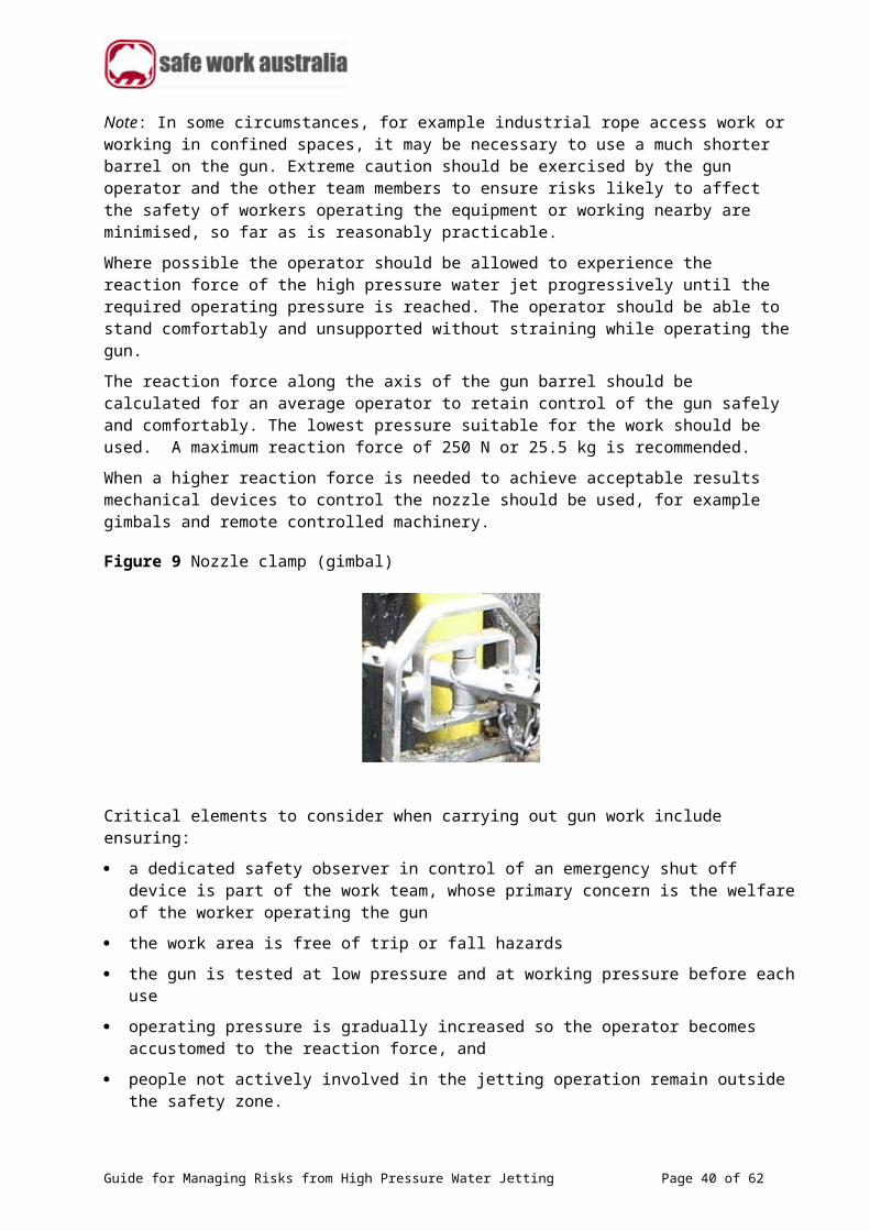
Nozzle Ø mm
Part-No.
Operating pressure - bar
200 300 400 500 600 700 750 800 900 1000 1100 1200 1300 1400 1500
Flow rate – L/min
Recoil force in jetting direction /(N)*
0,85 6,3
21
7,7
31
8,9
41
9,9
52
10,9
62
11,7
72
12,1
78
12,5
83
13,3
93
14,0
103
14,7
114
15,3
124
16,0
134
16,6
145
17,2
155
0,90 7,0
23
8,6
35
9,9
46
11,1
58
12,2
70
13,1
81
13,6
87
14,0
93
14,9
104
15,7
116
16,5
128
17,2
139
17,9
151
18,6
162
19,2
174
0,95 7,8
26
9,6
39
11,1
52
12,4
65
13,6
78
14,6
90
15,2
97
15,7
103
16,6
116
17,5
129
18,4
142
19,2
155
20,0
168
20,7
181
21,4
194
1,00 8,7
29
10,6
43
12,3
57
13,7
72
15,0
86
16,2
100
16,8
107
17,3
115
18,4
129
19,4
143
20,3
157
21,2
172
22,1
186
22,9
200
23,7
215
1,05 9,6
32
11,7
47
13,5
63
15,1
79
16,6
95
17,9
110
18,5
118
19,1
126
20,3
142
21,4
158
22,4
174
23,4
189
24,4
205
25,3
221
26,2
237
1,10 10,5
35
12,9
52
14,8
69
16,6
87
18,2
104
19,6
121
20,3
130
21,0
139
22,3
156
23,5
173
24,6
191
25,7
208
26,7
225
27,8
242
28,7
260
1,15 11,5
38
14,0
57
16,2
76
18,1
95
19,9
114
21,5
133
22,2
142
22,9
151
24,3
170
25,6
189
26,9
208
28,1
227
29,2
246
30,3
265
31,4
284
1,20 12,5
41
15,3
62
17,7
82
19,7
103
21,6
124
23,4
144
24,2
155
25,0
165
26,5
184
27,9
206
29,3
227
30,6
247
31,8
268
33,0
289
34,2
309
Guide for Managing Risks from High Pressure Water Jetting Page 40 of 46
Nozzle Ø mm
Part-No.
Operating pressure - bar
1600 1700 1800 1900 2000 2100 2200 2300 2400 2500 2600 2700 2800 2900 3000
Flow rate – L/min
Recoil force in jetting direction /(N)*
0,15 0,6
5
0,6
5
0,6
6
0,6
6
0,6
6
0,6
7
0,6
7
0,7
7
0,7
8
0,7
8
0,7
8
0,7
9
0,7
9
0,7
9
0,8
10
0,20 1,0
9
1,0
10
1,0
10
1,1
11
1,1
11
1,1
12
1,2
13
1,2
13
1,2
14
1,2
14
1,3
15
1,3
15
1,3
16
1,3
17
1,3
17
0,25 1,5
14
1,6
15
1,6
16
1,7
17
1,7
18
1,8
19
1,8
20
1,8
21
1,9
21
1,9
22
2,0
23
2,0
25
2,0
25
2,1
26
2,1
27
0,30 2,2
21
2,3
22
2,3
23
2,4
24
2,5
26
2,5
27
2,6
28
2,6
30
2,7
31
2,8
32
2,8
33
2,9
35
2,9
36
3,0
37
3,0
39
0,35 3,0
28
3,1
30
3,2
32
3,3
33
3,4
35
3,4
37
3,5
39
3,6
40
3,7
42
3,8
44
3,8
46
3,9
47
4,0
49
4,0
51
4,1
53
0,40 3,9
37
4,0
39
4,2
41
4,3
44
4,4
46
4,5
48
4,6
50
4,7
53
4,8
55
4,9
57
5,0
60
5,1
62
5,2
64
5,3
66
5,4
69
0,45 5,0
46
5,1
49
5,3
52
5,4
55
5,6
58
5,7
61
5,8
64
6,0
67
6,1
70
6,2
72
6,3
75
6,5
78
6,6
81
6,7
84
6,8
87
0,50 6,1
57
6,3
61
6,5
64
6,7
68
6,9
72
7,0
75
7,2
79
7,4
82
7,5
86
7,7
89
7,8
93
8,0
97
8,1
100
8,3
104
8,4
107
0,55 7,4
69
7,6
74
7,9
78
8,1
82
8,3
87
8,5
91
8,7
95
8,9
100
9,1
104
9,3
108
9,5
113
9,6
117
9,8
121
10,0
126
10,2
130
0,60 8,8
82
9,1
88
9,4
93
9,6
98
9,9
103
10,1
108
10,4
113
10,6
119
10,8
124
11,0
129
11,3
134
11,5
139
11,7
144
11,9
149
12,1
155
0,65 10,4
97
10,7
103
11,0
109
11,3
115
11,6
121
11,9
127
12,2
133
12,4
139
12,7
145
13,0
151
13,2
157
13,5
163
13,7
169
14,0
175
14,2
181
Guide for Managing Risks from High Pressure Water Jetting Page 41 of 46
Guide for Managing Risks from High Pressure Water Jetting Page 42 of 46
Nozzle Ø mm
Operating pressure - bar
1600 1700 1800 1900 2000 2100 2200 2300 2400 2500 2600 2700 2800 2900 3000
Flow rate – L/min
Recoil force in jetting direction /(N)*
0,70 12,0
112
12,4
119
12,7
126
13,1
133
13,4
140
13,8
147
14,1
154
14,4
161
14,7
168
15,0
175
15,3
182
15,6
189
15,9
196
16,2
203
16,5
210
0,75 13,8
129
14,2
137
14,6
145
15,0
153
15,4
161
15,8
169
16,2
177
16,5
185
16,9
193
17,2
201
17,6
209
17,9
217
18,2
225
18,6
233
18,9
242
0,80 15,7
147
16,2
156
16,6
165
17,1
174
17,5
183
18,0
192
18,4
202
18,8
211
19,2
220
19,6
229
20,0
238
20,4
247
20,8
257
21,1
266
21,5
275
0,85 17,7
165
18,3
176
18,8
186
19,3
196
19,8
207
20,2
217
20,8
228
21,2
238
21,7
248
22,1
259
22,6
269
23,0
279
23,4
290
23,9
300
24,3
310
0,90 19,9
186
20,5
197
21,1
209
21,6
220
22,2
232
22,8
243
23,3
255
23,8
267
24,3
278
24,8
209
25,3
301
25,8
313
26,3
325
26,7
336
27,2
348
0,95 22,1
207
22,8
220
23,5
233
24,1
245
24,7
258
25,4
271
26,0
284
26,5
297
27,1
310
27,7
323
28,2
336
28,8
349
29,3
362
29,8
375
30,3
388
1,00 24,5
229
25,3
243
26,0
258
26,7
272
27,4
286
28,1
301
28,8
315
29,4
329
30,0
344
30,7
358
31,3
372
31,9
386
32,4
401
33,0
415
33,6
429
1,05 27,0
252
27,9
268
28,7
284
29,5
300
30,2
316
31,0
331
31,7
347
32,4
363
33,1
379
33,8
395
34,5
410
35,1
426
35,8
442
36,4
458
37,0
473
1,10 29,7
277
30,6
294
31,5
312
32,3
329
33,2
346
34,0
364
34,8
381
35,6
398
36,3
416
37,1
433
37,8
450
38,6
468
39,3
485
40,0
502
40,6
520
1,15 32,4
303
33,4
322
34,4
341
35,3
360
36,3
379
37,2
398
38,0
416
38,9
435
39,7
454
40,5
473
41,3
492
42,1
511
42,9
530
43,7
549
44,4
568
1,20 35,3
330
36,4
350
37,5
371
38,5
392
39,5
421
40,5
433
41,4
453
42,3
474
43,3
495
44,1
515
45,0
536
45,9
557
46,7
577
47,5
598
48,4
618
Guide for Managing Risks from High Pressure Water Jetting Page 43 of 46
Guide for Managing Risks from High Pressure Water Jetting Page 44 of 46
APPENDIX E – HAND SIGNALS
The following set of hand signals may be used for communicating when carrying out high pressure water jetting operations.
Figure 11 Hand signals
Guide for Managing Risks from High Pressure Water Jetting Page 45 of 46
APPENDIX F – OTHER REFERENCE MATERIAL
The following list of published technical standards provide guidance only. Compliance with them does not guarantee compliance with the WHS Act and Regulations in all instances. This list is not exhaustive.
AS/NZS 1269.3: 2005 Occupational noise management, Part 3 Hearing protector program
AS/NZS 1270: 2002 Acoustics, hearing protectors
AS 1319-1994 Safety signs for the occupational environment
AS/NZS: 1337 (Series) 2010, Amdt 1-2012, 2012 Personal eye protection
AS/NZS: 1715 2009 Selection, use and maintenance of respiratory protective equipment
AS 1742.3-2009 Manual of uniform traffic control devices, Part 3 Traffic control for works on roads
AS/NZS 1801: 1997, Amdt 1-1999 Occupational protective helmets
AS/NZS 2210.1: 2010 Safety, protective and occupational footwear, Part 1 Guide to selection, care and use
AS/NZS 2210.2: 2009 Occupational protective footwear, Part 2 Test methods
AS/NZS 2161.2: 2005 Occupational protective gloves, Part 2 General requirements
AS/NZS 2161.3: 2005 Occupational protective gloves, Part 3 Protection against mechanical risks
AS/NZS 2161.5: 1998 Occupational protective gloves, Part 5 Protection against cold
AS/NZS 3000: 2007, Amdt 1-2009, Amdt 2-2012 Electrical installations
AS 3765.1-1990, Clothing for protection against hazardous chemicals, Part 1 Protection against general or specific chemicals
AS 3765.2-1990, Clothing for protection against hazardous chemicals, Part 2 Limited protection against specific chemicals
AS 3791-1991, Amdt 1-1991, Amdt 2-1995 Hydraulic hose
AS/NZS 4233.1-1999 High pressure water (hydro) jetting systems, Part 1 Guidelines for safe operation and maintenance
AS/NZS 4233.1-1999 High pressure water jetting systems, Part 1 Safe operation and maintenance
AS/NZS 4233.2-1999 High pressure water (hydro) jetting systems, Part 2 Construction and performance
AS/NZS 4233.2-1999 High pressure water jetting systems, Part 2 Construction and performance
Guide for Managing Risks from High Pressure Water Jetting Page 46 of 46