Embed Size (px)
Citation preview

International Civil Aviation Organization
SAM Region
GUIDE FOR THE IMPLEMENTATION
OF AIDC
THROUGH THE INTERCONNECTION
OF
ADJACENT AUTOMATED CENTRES
Lima, Peru – April 2013

-2-
Guide for the implementation of AIDC through the interconnection of adjacent automated centres
TABLE OF CONTENTS REFERENCES ..................................................................................................................................4 PURPOSE .........................................................................................................................................5 SCOPE ..............................................................................................................................................5 CHAPTER I .......................................................................................................................................6 1. GENERAL ............................................................................................................................6 1.1. Introduction ...........................................................................................................................6 1.2 Capacity and growth ...............................................................................................................6 CHAPTER II .....................................................................................................................................8 2. TECHNICAL ASPECTS FOR THE IMPLEMENTATION OF AIDC BETWEEN
ADJACENT AUTOMATED SYSTEMS .................................................................................8 2.1. Introduction ...........................................................................................................................8 2.2. Communication considerations for the interconnection of automated centres ..............................8 2.3. Phases to be taken into account for the implementation of AIDC between adjacent
automated centres of different States ......................................................................................12 2.4. Prepare the memorandum of understanding between the States ................................................12 2.5. Provision of connectivity between an AMHS server or AFTN CCAM or dedicated
channel and the automated system .........................................................................................13 2.6. Establish physical and logical connectivity between States ......................................................14 2.7. Possible scenarios .................................................................................................................16 2.8. Create the required AMHS or AFTN user accounts (mailbox) .................................................19 2.9. Verify the user accounts ........................................................................................................21 2.10. Incorporate user accounts to the automated systems that support AIDC ....................................21 2.11. Establish a test protocol ........................................................................................................21 2.12. Conduct pre-operational tests ................................................................................................22 2.13. Conduct operational tests ......................................................................................................22 2.14. Establish and define the definitive operating stages .................................................................22 2.15. Associated automation functionality ......................................................................................22 2.16. Solutions or recommendations in case of failure or recovery....................................................22 2.17. Security considerations .........................................................................................................23 2.17.1. Privacy ............................................................................................................................... 23 2.17.3. Authentication ..................................................................................................................... 24 2.17.4. Access control ..................................................................................................................... 24 2.18. Performance considerations ...................................................................................................24 2.19. Availability and reliability .................................................................................................... 25 CHAPTER III ..................................................................................................................................26 3. OPERATIONAL ASPECTS FOR THE IMPLEMENTATION OF AIDC BETWEEN
ADJACENT AUTOMATED SYSTEMS ...............................................................................26 3.1. Introduction .........................................................................................................................26 3.2. Letter of Operational Agreement ...........................................................................................26 3.3. Minimum AIC message set ...................................................................................................27 3.4. AIDC procedures ..................................................................................................................27 3.4.1. Notification stage ................................................................................................................ 27

-3-
Guide for the implementation of AIDC through the interconnection of adjacent automated centres
3.4.2. Coordination stage ............................................................................................................... 28 3.4.3. Negotiation stage ................................................................................................................. 28 3.4.4. Transfer stage ...................................................................................................................... 29 3.5. Flow chart ............................................................................................................................30 3.6. Implementation testing phases ...............................................................................................30 3.6.1. First phase........................................................................................................................... 30 3.6.2. Second phase ...................................................................................................................... 31 3.6.3. Third phase ......................................................................................................................... 31 3.6.4. Fourth phase ....................................................................................................................... 31 APPENDIX A – SAM REDDIG IPv4 LAN addressing plan by State ...................................................... A1 APPENDIX B – SAM REDDIG IPv4 WAN addressing plan for interconnection between States ...........B1 APPENDIX C – IPv4 addressing for AIDC application ............................................................................C1 APPENDIX D – Composition of ATS messages ...................................................................................... D1 APPENDIX E – Glossary ........................................................................................................................... E1 LIST OF TABLES Tabla 1. Configuración CH AFTN ............................................................................................................... 9 Tabla 2. Direcciones AFTN/AMHS ........................................................................................................... 20 Tabla 3. Requisitos de rendimiento............................................................................................................. 24 Tabla 4. Set de mensajes ATC .................................................................................................................... 27 LIST OF GRAPHS Graph 1. AFTN/AMHS scenario (source: Skysoft) Graph 2. Channel display for a SAEZ gateway administrator Graph 3. Schematic of gateway function Graph 4. Possible last-mile connectivity scenarios Graph 5. Illustration of a case in which the AIDC message telecommunication access node is far from the automated centre Graph 6. Integration of AIDC users of adjacent centres Graph 7. OSI model reference Graph 8. Verification of address translation Graph 9. Example of AIDC topology using the SAM REDDIG IPv4 Graph 10. Configuration of the AIDC account in the AMHS system Graph 11. Configuration of the CADI account in the AMHS system Graph 12. AIDC configuration

-4-
Guide for the implementation of AIDC through the interconnection of adjacent automated centres
REFERENCES Document ID Name of document ICAO 4444 Air Traffic Management ICAO Annex 10, Volume II Aeronautical Telecommunications ICAO Annex 11 Air Traffic Services ICAO Doc 9694 Manual of Air Traffic Services – Data Link Applications ICAO Doc 9880 Manual on Detailed Technical Specifications for the
Aeronautical Telecommunication Network (ATN) using ISO / OSI Standards and Protocols PART II – Ground-Ground Applications Between ATS Data Communication Facilities (AIDC)
Asia/Pacific Regional Doc Asia/Pacific Regional ICD for AIDC CAR/SAM ICD Doc CAR/SAM AIDC ICD

-5-
Guide for the implementation of AIDC through the interconnection of adjacent automated centres
PURPOSE The purpose of this document is to serve as practical guidance for the implementation of AIDC between two adjacent automated centres of the SAM Region. The development of this document for the implementation of AIDC and its interconnection is contemplated amongst the activities of Regional Project RLA/06/901, Assistance for the implementation of a regional ATM system, taking into account the ATM operational concept and the corresponding technological support in communications, navigation and surveillance (CNS). This document will support the States of the Region in the implementation of AIDC through the interconnection of automated systems between adjacent ACCs, and its development was discussed at the Tenth Workshop/Meeting of the SAM Implementation Group (SAM/IG/10), held in Lima on 1-5 October 2012, and approved by the Sixth Coordination Meeting of Project RLA/06/901 (Lima, 21-23 November 2012). SCOPE The two main aspects contained in this document for AIDC implementation are:
technical aspects operational aspects
implemented in a setting of adjacent automated centres.

-6-
Guide for the implementation of AIDC through the interconnection of adjacent automated centres
CHAPTER I 1. GENERAL 1.1. Introduction 1.1.1. One of the key features of the future air traffic management system is the bidirectional exchange of data between the aircraft and the ATC system, and between ATC systems. Communications with the aircraft increasingly tend towards the use of digital data links. At the same time, the automatic exchange of data between ATC systems will support the timely broadcast of flight data, especially for coordination and transfer of flights between ATS units. 1.1.2. The AIDC application shall provide important benefits, including:
a) Reduced controller workload; b) Reduction in the number of read-back/hear-back errors during coordination; c) Reduction in the number of gross navigation errors and large height deviations
caused by errors in the “controller-to-controller” coordination loop; d) Gradual replacement of the ATS speech service as main coordination tool.
1.1.3. AIDC permits the exchange of information between ATS units in support of critical ATC functions. This includes the reporting of flights approaching a border flight information region (FIR), coordination of border crossing conditions, and transfer of control. 1.1.4. The AIDC provides interoperability between automated systems, enabling the exchange of data between ATSUs that are harmonised to a common standard. AIDC supports reporting, coordination and transfer of communications and control functions between these ATSUs. The capacity provided by the AIDC is compatible with a greater flexibility in separation minima applied in the adjacent airspace. The AIDC promotes seamless transfer of aircraft between the participating ATSUs. 1.1.5. AIDC defines the messages related to the three coordination phases as perceived by an ATSU.
a) reporting phase, in which the path of the aircraft and any change may be broadcast to an ATSU from the current ATSU prior to coordination;
b) coordination phase, in which the path of the aircraft is coordinated between two or
more ATSUs when the flight is approaching a common border; and c) transfer phase, in which communications and executive control are transferred from
one ATSU to another. 1.2 Capacity and growth 1.2.1 Before implementing this interface between two automated centres, an analysis will be done of traffic expected between the centres. Also, the proposed communication links will be verified to make sure they meet the requirements for this purpose. Traffic estimates must take into account expected, current and future traffic levels.

-7-
Guide for the implementation of AIDC through the interconnection of adjacent automated centres
1.2.2 Furthermore, the strategies developed by the SAM Region for the integration of automated ATM systems based on a safe, gradual, evolutionary and interoperable vision must be adopted. This will facilitate the exchange of information and collaborative decision-making amongst all the components of the ATM system, resulting in transparent, flexible, optimum, and dynamic airspace management.

-8-
Guide for the implementation of AIDC through the interconnection of adjacent automated centres
CHAPTER II 2. TECHNICAL ASPECTS FOR THE IMPLEMENTATION OF AIDC BETWEEN
ADJACENT AUTOMATED SYSTEMS 2.1. Introduction 2.1.1. When referring to AIDC-related communications, it should be noted that AIDC is an ATN application used for the exchange of ATS information between two units that have automated centres that support its implementation. 2.1.2. AIDC allows for the exchange of ATS information about active flights, with respect to flight notification, coordination, transfer of control, surveillance data and free text data. 2.1.3. When talking about this automated exchange, we are basically referring to ATS interfacility data communication (AIDC), as defined by ICAO. 2.1.4. Although technical provisions have been defined in various documents cited in this document, the current scenario in the SAM Region calls for an AIDC conceived in function of the means of telecommunication and facilities available in the States. 2.1.5. At present, the SAM Region has different systems and a multiservice platform (REDDIG) that are optimal and adequate. Consequently, the Region must work on three relevant elements: the concrete use of the AMHS system, the incorporation of automated systems that support AIDC, and a multiservice platform like REDDIG (the future REDDIG II) based on IP MPLS. 2.1.6. Beyond the various examples we can find—for example, the Asia/Pacific AIDC ICD--, this chapter will address the platforms and means that SAM States have or will have available in the short term. In this sense, emphasis will be placed on the AMHS and the ATN IP network for the implementation of AIDC. 2.1.7. Although this document is mainly aimed at becoming a practical guide, the technical provisions on AIDC defined in ICAO Doc 9880, Part II A, Ground-ground applications -AIDC (in replacement of ICAO Doc 9705/sub-volume III) must be taken into account. 2.1.8. It should be noted that the provisions on AIDC are also contained in ICAO Doc 4444, Chapter 11. 2.1.9. Although there are no communication protocols or physical path set for AIDC, different recommendations and practical references will be presented to facilitate implementation. 2.2. Communication considerations for the interconnection of automated centres 2.2.1. First of all, it should be noted that coordination can take place between the following ATSUs: ACC and ACC, ACC and APP, APP and APP, and APP and TWR. 2.2.2. It should be noted that, at present, the Plan for the Interconnection of Adjacent Automated Centres of the SAM Region, as relates to AIDC systems between the States, can be implemented in three ways:

-9-
Guide for the implementation of AIDC through the interconnection of adjacent automated centres
1) AFTN: message format using the ITA-2 or IA-5 protocol, and using the header field for optional information (Vol. II, Annex 10, 4.4.15.2.2.6). It has a length of 69 characters. Implementation is recommended through REDDIG node ports. The caveat is that it only accepts the ASCII format.
The typical configuration of an AFTN channel is shown below.
AFTN Interface Parameters
Type Synchronous - Asynchronous
Data AIDC
Format ICAO
Message identification ABI, CPL, CDN, FPL, EST, ACP, LAM, LRM, RJC, TOC, AOC
Message definition Ref. Doc 4444
Data rate 1200 bps/ 9600bps/2400 bps
Physical connection 25 pin type “D”
Electrical characteristics RS232c V24/V28
Data bits, parity, stop bits, protocol 8 bits, NP, 1 stp, IA-5 / ITA- 2
Table 1. AFTN channel configuration
2) Dedicated channel (point-to-point): involves the use of dedicated lines that meet safety and performance requirements. It is recommended that this be used through the REDDIG, and depending on the ports to be used.
3) AMHS: uses the REDDIG WAN network, whether over frame relay or an MPLS IP
network, and applying the recommendations concerning the SAM REDDIG IP Plan. It is important to highlight the importance of interconnecting the MTAs between States as a precondition.
In the case of the AMHS, the required bandwidth is 4,8 Kbps and 14,4 Kbps (taking into account the additional bandwidth) (see Doc SAM ATN – Study on the implementation of a new digital network for the SAM Region (REDDIG II)).
2.2.3. The following graph illustrates a scenario with the different components of an AMHS architecture coexisting with AFTN.

-10-
Guide for the implementation of AIDC through the interconnection of adjacent automated centres
TAU terminals in RAS network
Graph 1 - AFTN/AMHS scenario (source: Skysoft)
• UA: User agents (the customers, in this case, AIDC). • MS: Message storage for handling message delivery and retrieval. • MTA: Agent responsible for routing messages between MTAs, MSs and UAs. • P7: Protocol used for retrieval from the MS (ITU-T X.413) (“push” type) by the UA • P3: Delivery protocol (“pull” type) • P1: Protocol for communicating and routing messages between MTAs (ITU-T X.411) • DS: Directory server that communicates using X.500 protocols
2.2.4. Regarding the bandwidth required for the three aforementioned cases, document SAM ATN – Study on the implementation of a new digital network for the SAM Region (REDDIG II)), states the following: In the case of AFTN and AMHS, “these are AFTN messages generated/received by automated systems, which travel over the respective AFTN or AMHS systems (or a combination of both). Accordingly, the increase in the amount of information will only result as an increase in the number of AFTN messages circulating through the ATN”. 2.2.5. “Since ATS traffic has historically accounted for only 15% of total AFTN traffic, assuming a 3-fold increase (300%) of ATS messages, this will only result in a 30% increase in AFTN traffic”.

-11-
Guide for the implementation of AIDC through the interconnection of adjacent automated centres
2.2.6. In the case of a dedicated link, each centre will send the information to the corresponding adjacent centre, and the bandwidth will be increased in function of the number of control messages to be generated by each automated centre, which will obviously be a function of surrounding air traffic. 2.2.7. This ICD mainly refers to the implementation of AIDC based on AMHS and AFTN systems. 2.2.8. AIDC messages will be exchanged through the AFTN and the AMHS. However, AFTN/AMHS gateways shall be used to allow the two systems to continue coexisting, both at present and in the future. Accordingly, these gateways convert AFTN messages to the AMHS format and vice versa.
Graph 2 – Channel display for a SAEZ gateway administrator
Graph 3 – Schematic of gateway function
-12-
Guide for the implementation of AIDC through the interconnection of adjacent automated centres
2.2.9. It should be noted that in 2005, SAM States decided to start replacing their AFTN aeronautical messaging systems with AMHS messaging systems, which have been implemented over IP networks (version 4), especially for the interconnection of MTAs between States. 2.3. Phases to be taken into account for the implementation of AIDC between adjacent
automated centres of different States 2.3.1. A practical guide on the steps to follow to ensure an effective implementation of AIDC for coordination between adjacent automated centres of different States should take into account the following aspects. 2.3.2. As already stated, this mainly refers to the use of the means already available or to be implemented in the short term in the States. 2.3.3. In conclusion, the following items must be taken into account:
1) Drafting of the memorandum of understanding between the States 2) Provision of connectivity between the AMHS server or AFTN CCAM or dedicated
channel and the automated system 3) Establish the physical and logical connection between the States 4) Create the required AMHS or AFTN user accounts (mailbox) 5) Verify the user accounts 6) Incorporate user accounts into the automated systems that support AIDC 7) Establish a test protocol 8) Conduct pre-operational tests 9) Conduct operational tests 10) Establish and define definitive operating stages (letters of agreement)
2.4. Prepare the memorandum of understanding between the States 2.4.1. First, the States must sign a memorandum of understanding (bilateral agreement) clearly expressing the commitment of the parties to implement the interconnection of automated air traffic systems, especially for AIDC. 2.4.2. Basically, this document must contain the references on which the work will be based; the purpose; the operational, technical, administrative and financial aspects; and everything that the intervening States deem important to include in the document. 2.4.3. It is important to note that, for purposes of the implementation, the States must identify the focal points (coordinators) to be responsible for coordinating the respective work teams to be established as required (that is, technical, operational or technical-operational teams). 2.4.4. These focal points (coordinators) shall be designated by an Interconnection Management Committee, which, in turn, will be composed of a Coordinator, a Technical Group, and an Operational Group.

-13-
Guide for the implementation of AIDC through the interconnection of adjacent automated centres
2.4.5. The SAM Implementation Group (SAM/IG) approved the use of a model Memorandum of Understanding (MoU) for the interconnection of automated systems (fourth workshop/meeting of the SAM Implementation Group (SAM/IG/4) – Regional Project RLA/06/901, Lima, 19-23 October 2009). The MoU can be found in the SAM/IG/4 meeting report, Agenda Item 7, Appendix B, at the ICAO SAM Regional Office Website. 2.5. Provision of connectivity between an AMHS server or AFTN CCAM or dedicated
channel and the automated system 2.5.1. The first thing that must be available in each State is the connectivity between the AMHS server, or AFTN CCAM, or the dedicated channel (which is supposedly integrated to its users), whether through a TCP/IP platform, synchronous/asynchronous port, or dedicated channel, respectively. Within this framework, it is understood that the connection between the telecommunication node (that physically hosts the connection that allows linkage with the other State) and the automated system will be achieved through the IP network, or local gateway, or specific cabling, as applicable.
Graph 4 – Possible last-mile connectivity scenarios
2.5.2. In this regard, the aforementioned would seem of minor significance, since the respective telecommunication node or server is generally close to the automated centre. But this aspect acquires significance when considering those cases in which structured cabling and physical interface standards (distance factor, cable characteristics, connector, protocol, etc.) demand technical solutions that may require economic resources. For example: State A has a local IP network at the same location as the REDDIG telecommunication node, and the automated system is located in B, which is in another city or at a distance greater than 100 meters. 2.5.3. In this example, this is an important factor to bear in mind due to technical-administrative timings and the budgetary element involved. This is an important aspect since it could affect implementation times and thus the bilateral agreement.

-14-
Guide for the implementation of AIDC through the interconnection of adjacent automated centres
2.5.4. We know that an automated centre receives the flight plans and it is to be assumed that, given the above scenario, the aforementioned would be no major problem. However, it should be taken into account, especially when talking about point-to-point connections.
Graph 5 – Illustration of the case in which the AIDC message telecommunication access node is far
from the automated centre
2.6. Establish physical and logical connectivity between States 2.6.1. Once local connectivity is achieved, physical and logical connectivity between the States must be established. 2.6.2. For the completion of this phase, the tools and means available in the SAM Region to implement AIDC between the States are presented below. 2.6.3. REDDIG. Regional multi-service platform 2.6.4. It should be first noted that the REDDIG is a multi-service platform on which the physical and logical connectivity between States for AIDC must be established. Furthermore, this network currently permits both AFTN and AMHS traffic.
-15-
Guide for the implementation of AIDC through the interconnection of adjacent automated centres
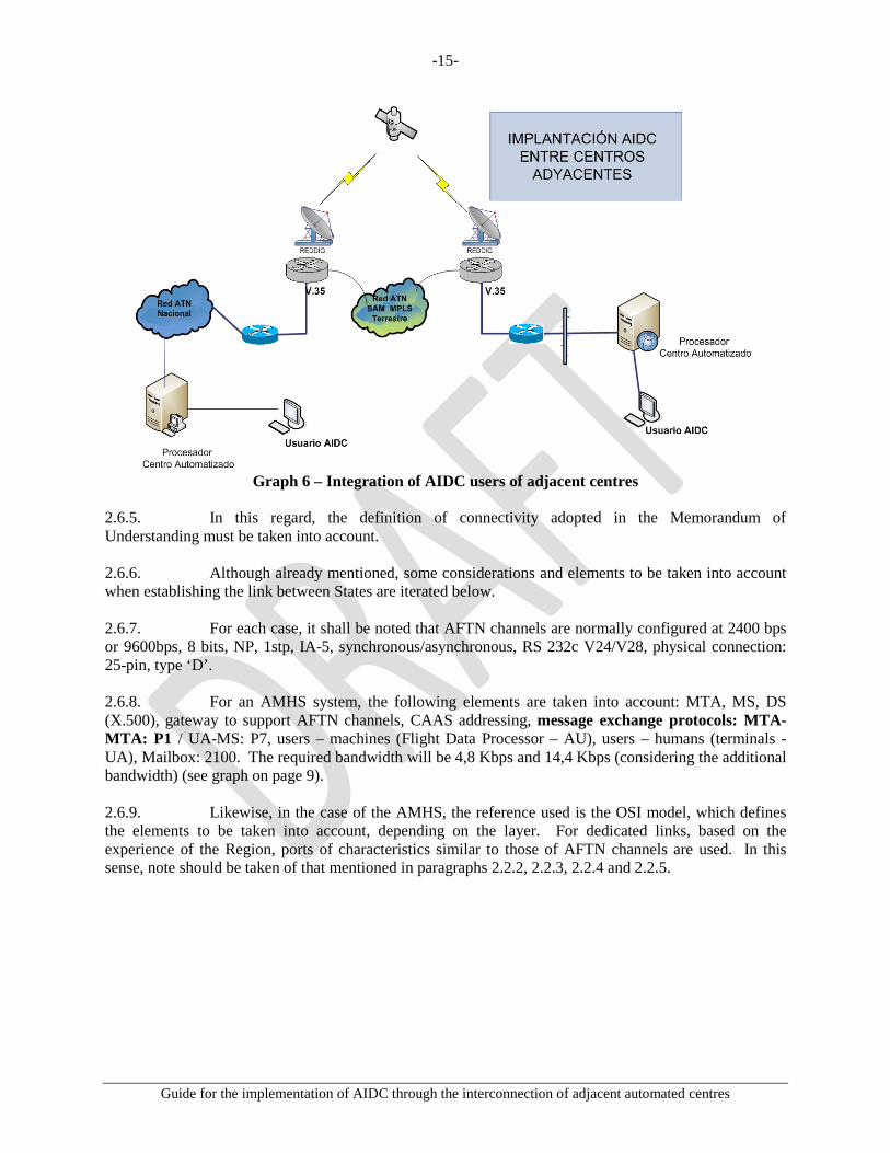
Graph 6 – Integration of AIDC users of adjacent centres
2.6.5. In this regard, the definition of connectivity adopted in the Memorandum of Understanding must be taken into account. 2.6.6. Although already mentioned, some considerations and elements to be taken into account when establishing the link between States are iterated below. 2.6.7. For each case, it shall be noted that AFTN channels are normally configured at 2400 bps or 9600bps, 8 bits, NP, 1stp, IA-5, synchronous/asynchronous, RS 232c V24/V28, physical connection: 25-pin, type ‘D’. 2.6.8. For an AMHS system, the following elements are taken into account: MTA, MS, DS (X.500), gateway to support AFTN channels, CAAS addressing, message exchange protocols: MTA-MTA: P1 / UA-MS: P7, users – machines (Flight Data Processor – AU), users – humans (terminals - UA), Mailbox: 2100. The required bandwidth will be 4,8 Kbps and 14,4 Kbps (considering the additional bandwidth) (see graph on page 9). 2.6.9. Likewise, in the case of the AMHS, the reference used is the OSI model, which defines the elements to be taken into account, depending on the layer. For dedicated links, based on the experience of the Region, ports of characteristics similar to those of AFTN channels are used. In this sense, note should be taken of that mentioned in paragraphs 2.2.2, 2.2.3, 2.2.4 and 2.2.5.

-16-
Guide for the implementation of AIDC through the interconnection of adjacent automated centres
Graph 7 – OSI model reference
2.7. Possible scenarios 2.7.1. Currently, most SAM States have incorporated AMHS. In reality however not all States have interconnected their MTAs. Therefore, those States that have AMHS also have an associated gateway that does the conversion from the AMHS “world” to the AFTN “world” and vice versa. This is an important issue to be taken into account during AIDC implementation. 2.7.2. Connectivity through asynchronous ports. This case may be applied both to a dedicated link or to an AFTN application. 2.7.3. Paragraph 2.6.6 and Doc 9880 must be taken into account. 2.7.4. Connectivity through an IP network. Currently, there is a REDDIG IPv4 Addressing Plan in the SAM Region, Appendices A and B, which establishes 8190 IP addresses assigned to each State. It is understood that this availability of addresses would be enough to meet current needs. 2.7.5. Furthermore, the SAM REDDIG IPv4 addressing plan gives flexibility to each State/Territory in the design of its ATN networks and in local implementation of aeronautical applications over IP networks. Likewise, this scheme takes into account future requirements based on address availability. 2.7.6. In order to establish this type of link between States, some physical and logical aspects must be considered.
a. Follow the REDDIG IPv4 addressing scheme set for the Region. b. Identify the physical port to be used for connecting to the networking equipment of
the State network (router) c. Define, if applicable, the V.35 DCE/DTE interface or protocol
-17-
Guide for the implementation of AIDC through the interconnection of adjacent automated centres
d. Set the configuration parameters for networking equipment: * Type of encapsulation * DLCI for frame relay, or port priority (QoS) for MPLS, * Type of LMI protocol for frame relay, * REDDIG WAN IP address (see SAM REDDIG IPv4 addressing plan, Annex C,
graph 9). * REDDIG LAN IP address (see SAM REDDIG IPv4 addressing plan, Annex B,
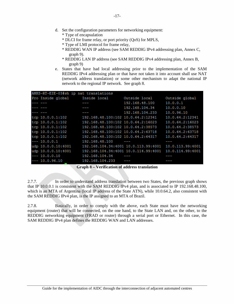
graph 9) e. States that have had local addressing prior to the implementation of the SAM
REDDIG IPv4 addressing plan or that have not taken it into account shall use NAT (network address translation) or some other mechanism to adapt the national IP network to the regional IP network. See graph 8.
Graph 8 – Verification of address translation
2.7.7. In order to understand address translation between two States, the previous graph shows that IP 10.0.0.1 is consistent with the SAM REDDIG IPv4 plan, and is associated to IP 192.168.48.100, which is an MTA of Argentina (local IP address of the State ATN), while 10.0.64.2, also consistent with the SAM REDDIG IPv4 plan, is the IP assigned to an MTA of Brazil. 2.7.8. Basically, in order to comply with the above, each State must have the networking equipment (router) that will be connected, on the one hand, to the State LAN and, on the other, to the REDDIG networking equipment (FRAD or router) through a serial port or Ethernet. In this case, the SAM REDDIG IPv4 plan defines the REDDIG WAN and LAN addresses.

-18-
Guide for the implementation of AIDC through the interconnection of adjacent automated centres
2.7.9. The connection scheme described above is shown below.
Graph 9 – Example of AIDC topology using the SAM REDDIG IPv4
2.7.10. After verifying the connection between the end networking units and the connectivity with the respective local networks, the following phases shall be implemented. 2.7.11. Taking into account the SAM REDDIG IPv4 addressing plan for REDDIG LAN networks (see Appendix A), each State may use the addresses and the addressing scheme of its choice. Nevertheless, a redistribution of network segments is proposed in Appendix C. 2.7.12. The purpose of this recommendation is to be able to specify what network segments will be assigned to certain services. It basically means dividing the REDDIG LAN networks of each State into VLANs. But these VLANs must have the same structure in all States. 2.7.13. This recommendation is not only intended for application in AIDC but also in all current and future services to be exchanged between SAM States. It also permits the establishment of a pre-established order that will contribute to an orderly implementation of services (see Annex D to this document).

-19-
Guide for the implementation of AIDC through the interconnection of adjacent automated centres
2.7.14. It is also advisable that:
1) Network addresses are assigned in continuous blocks. 2) Address blocks are distributed in hierarchical order to enable routing scalability. 3) Sub-network configuration is made possible in order to take maximum advantage of
each assigned network (subnetting). 4) Super-network configuration is made possible in order to take maximum advantage
of each assigned network (supernetting) 5) The quality of service in an MPLS (REDDIG II) environment is specified.
2.7.15. The only assigned addresses that are known to the rest of the States will be those of the interfaces of the communication equipment used at the interconnection boundaries between the internal and external networks of each State. 2.7.16. For the interconnection between their bordering equipment, the States will agree on the routing protocol to be used, unless REDDIG II implementation requires otherwise. 2.7.17. Each State shall ensure routing through its network to the internal address(es) of the application servers it uses vis-a-vis other States. 2.7.18. The Regional Office, by virtue of the corresponding institutional arrangements, will coordinate the implementation of the selected regional routing. 2.8. Create the required AMHS or AFTN user accounts (mailbox) 2.8.1. At this point, the user accounts that will operate with AIDC for the interconnection between automated centres must be defined. In this regard, it should be noted that the eight-letter designator would not be affected whether AMHS or AFTN systems are used. 2.8.2. This is relevant for AMHS because the address of the AMHS server must be associated to a REDDIG IPv4 address of the SAM addressing plan. For example: the AIDC user of State A, in addition to its eight-letter address, will be associated to an IP address of the national ATN. When the AIDC user of State A sends an AIDC message to an AIDC user of adjacent State B, the AMHS server will interpret that it is a message for State B. At this point, two things may happen:
1) If both States have an AMHS system and the respective MTAs are interconnected, traffic shall be routed through an IP address specified in the SAM REDDIG IPv4 plan and associated to the servers of the States.
2) If neither State has AMHS, or one does and the other one does not, or both have it
but their MTAs are not interconnected, traffic will be routed to the gateway so that it is transferred to the AFTN world; or will use the assigned AFTN port directly to the destination State. In the case of the AFTN, the channel must be configured in the gateway or AFTN system (data rate, type of channel, standard, type of interface, mode, etc.).

-20-
Guide for the implementation of AIDC through the interconnection of adjacent automated centres
2.8.3. According to the experience in Argentina, it is necessary to have at least two user accounts: one will be set for transmitting AIDC messages and the other for receiving AIDC messages. 2.8.4. In order to standardise user accounts, this document proposes that the last four letters of the assigned address should be: AIDC for transmission and CADI for reception. In this manner, all the personnel of the States of the Region will readily identify that the message belongs to AIDC. 2.8.5. Example: “Assuming the automated centres of Uruguay and Argentina are interconnected, the following addresses will be defined”:
AFTN/AMHS address for transmission
AFTN/AMHS address for reception
Uruguay SUMUAIDC SUMUCADI
Argentina SAEZAIDC SAEZCADI Table 2. AFTN/AMHS addresses
Graph 10 – Configuration of the AIDC account in the AMHS system

-21-
Guide for the implementation of AIDC through the interconnection of adjacent automated centres
Graph 11 – Configuration of the CADI account in the AMHS system
2.9. Verify the user accounts 2.9.1. Although the operational verification of user accounts is simple and basic, it is a vital step prior to implementation, where members of the Technical Group and the Operational Group of the Interconnection Management Committee will test the delivery and reception of AIDC messages between AIDC accounts users. 2.9.2. To this end, test AFTN or AMHS terminals must be available and configured as if they were end users (automated systems). See Doc 9880 and Doc 4444. 2.9.3. For message transmission, the AIDC application requires that:
a) messages be generated and sent in the required time sequence; and b) messages be delivered in the order they are sent.
2.10. Incorporate user accounts to the automated systems that support AIDC 2.10.1. Once the proper operation of user accounts has been verified, the next step is to coordinate with the technical-operational personnel--which should be part of the Interconnection Management Committee--for their incorporation into the automated systems. 2.10.2. It is recommended that this task be fulfilled preferably in a simulator, if available. More details in this regard are provided in Chapter III of this document, which deals with operational aspects. 2.11. Establish a test protocol 2.11.1 Once user accounts have been incorporated into the automated system, the Interconnection Management Committee, which is made up by personnel from both States, will establish a test protocol based on that stated below.

-22-
Guide for the implementation of AIDC through the interconnection of adjacent automated centres
2.11.2 This protocol must cover all aspects related to AIDC operation. In this sense, Annex A contains a general model that must be enriched with the experience gained from various implementations between States. 2.12. Conduct pre-operational tests 2.12.1. The test protocol will permit the conduction of pre-operational tests. These tests must take place within a safe context to prevent these AIDC messages from entering the operational system that is operating at that moment. 2.12.2. Consideration should also be given to the requirement of informing all stakeholders, as necessary, about the conduction of these tests. 2.12.3. This part of the document is further explained in Chapter III. 2.13. Conduct operational tests 2.13.1. The direct participation of controllers is required for the conduction of operational tests. In this regard, it should be noted that for satisfactory conduction of these tests, controllers must work with the AIDC for a period of at least four (4) hours in two (2) days. These parameters shall be defined based on experience and minimum time required. 2.14. Establish and define the definitive operating stages 2.14.1. Although Chapter III will provide more details in this respect, it must be noted outright that stages need to be defined. Basically:
a) in the first stage, the AIDC will support speech coordination between centres. b) in the second stage, the opposite will occur, where speech communication will
support the AIDC system. 2.15. Associated automation functionality 2.15.1. Each ATS service provider must be required to have the necessary support in each automation system that is implemented or to be implemented in order to be initially capable of:
• Error verification: check all incoming messages for the right format and logical consistency
• Making sure that only messages from authorised senders are accepted and processed • When necessary, alerting the responsible controller about the flight data received. • Making sure that the appropriate personnel can configure the logical-automatic
response time of a message initiated at the other control unit. 2.16. Solutions or recommendations in case of failure or recovery 2.16.1. Automation systems may have different mechanisms for avoiding major failures and for error recovery. Basically, each participating system shall have the following characteristics:
-23-
Guide for the implementation of AIDC through the interconnection of adjacent automated centres
• If the recovery process preserves the current message number at the time of the occurrence, in the sequence established between each intervening system, the notification is not required.
• If the recovery process requires the resetting of the sequence number to 000, a means must be established to notify the receiver unit that message numbers have been reinitiated. This may be established as a procedure agreed between the parties instead of being automated.
2.16.2. Once a LAM is received, if a recovery process takes place following an occurrence, the CPL is not sent automatically, so any CPL for which a LAM had been received must be sent again. This is relevant if the system was able to recover information on the status of coordinated flight plans that have been coordinated and has no need to restore message sequence numbers. 2.17. Security considerations 2.17.1. Privacy 2.17.1.1. The ICD does not define mechanisms to ensure privacy. It may be assumed that data sent through this interface can be seen by undesired third parties, either by intercepting messages or through disclosure at the receiving centre. 2.17.1.2. All communications that require privacy must be identified, and communications and procedures properly defined. In this sense, it is recommended that mechanisms be used for preserving the confidentiality of information (e.g., firewalls, private networks, trained technical and administrative personnel, etc.). Thus the critical importance of using the REDDIG as part of a private network. 2.17.1.3. It is also recommended that, during coordination between the States, the security policy to be implemented be taken into account as a determining factor. Even more so if the trend is to use IP networks, regardless of the platform. 2.17.1.4. In order to avoid threats and vulnerabilities, these security policies should be aimed at:
• Protecting confidentiality • Preserving integrity • Ensuring availability
2.17.1.5. Security risks cannot be completed eliminated or prevented; however, they can be minimised through effective risk management and assessment. Although the future ATN network supported by the REDDIG II is not available for the non-aeronautical world, it is open to the aeronautical world. 2.17.1.6. ATN network users expect security measures to ensure:
• That users will only be able to carry out authorised tasks. • That users will only be able to obtain authorised information. • That users will not be able to damage the data, applications or the operating
environment of a system. • A system that can track user actions and the network resources to which these actions
have access.

-24-
Guide for the implementation of AIDC through the interconnection of adjacent automated centres
2.17.2. The “safety policy” is key to the implementation not only of AIDC but also of all the services in the Region. Consequently, special attention should be paid to the “Guidance on Safety for the Implementation of IP Networks”, Project D1, SAM ATN Architecture, April 2013. 2.17.3. Authentication 2.17.3.1. Each system must verify that messages received are from the source stated in Field 03, which identifies the message type designator, message number, and reference data (see Doc 4444). 2.17.4. Access control 2.17.4.1. Each system participating in the interface will implement access controls to ensure that the source of the message is authorised to send a given type of message and that it has the right authority over the flight in question. 2.18. Performance considerations 2.18.1. Communication systems. Requirements and parameters 2.18.2. In addition to the requirements specified in this document, all data link applications require that:
a) the probability of not receiving a message be 10-6 or less; b) the probability that a message not received is not be notified to the sender be 10-9 or
less; and c) the probability that a message is erroneously routed be 10-7 or less.
2.18.3. The figures in Table 3 reflect the various performance levels that may be selected for the provision of data link services. Depending on the level of service to be provided, a State may define its performance requirements based on factors such as separation minima applied, traffic density, or traffic flow.
Application Availability (%) Integrity Reliability
(%) Continuity
(%)
DLCI 99.9 10-6 99.9 99.9
ADS 99.996 10-7 99.996 99.996
CPDLC 99.9 10-7 99.99 99.99
FIS 99.9 10-6 99.9 99.9
AIDC 99.996 10-7 99.9 99.9
ADS-B 99.996 10-7 99.996 99.996 Table 3. Performance requirements
2.18.4. Except under catastrophic circumstances, and based on the previous parameters, there may only be one end-to-end interruption that shall not exceed 30 seconds. (End-to-end availability can be achieved through the provision of alternate communication routes wherever possible. In this sense, REDDIG II contemplates this scenario.)

-25-
Guide for the implementation of AIDC through the interconnection of adjacent automated centres
2.18.5. For flight planning messages, controllers need a failed message transmission indication within 60 seconds of the message being sent. Therefore, the response time from the moment a message is sent until a LAM (or LRM) is received shall be less than 60 seconds at least 99% of the time under normal operating conditions. However, this can vary depending on the requirements of each centre. This may be modified following an analysis to ensure service efficiency. 2.18.6. Consequently, the response time from the moment a message is sent until a LAM (or LRM) is received shall be less than 60 seconds at least 99% of the time under normal operating conditions. A fast response time is desirable and will result in more efficient operations. 2.19. Availability and reliability 2.19.1. The software and hardware resources required for providing an interface service to users in the SAM Region must be developed in such a way that reliability is inherent to interface availability, which should be at least the same as that for end-to-en systems (for example, 99,7% availability for the systems at each end, which operate with 99,7% reliability). 2.20. The technical considerations contained in this document for the implementation of AIDC between adjacent automated centres are supplemented with current appendices, annexes, guides, and documents.

-26-
Guide for the implementation of AIDC through the interconnection of adjacent automated centres
CHAPTER III 3. OPERATIONAL ASPECTS FOR THE IMPLEMENTATION OF AIDC
BETWEEN ADJACENT AUTOMATED SYSTEMS 3.1. Introduction 3.1.1. This application of data communications between air traffic control units is not intended to fully replace voice communications. Initially, it will supplement traditional (voice) communications and will gradually become the main coordination channel, supplemented by speech communication. 3.1.2. The notification, coordination and transfer stages will continue to be the same as those described in ICAO Doc 4444 in Chapter 10, with the difference that, when using an AIDC application, the intervention of the operator will be minimal. 3.1.3. AIDC messages will have the same format and content as those normally used, as shown in ICAO Doc 4444, Chapter 11. 3.2. Letter of Operational Agreement 3.2.1. Prior to AIDC implementation, a new letter of agreement between ATC units will be drafted, taking into account aspects concerning how much time in advance will messages be transmitted from one unit to the other. 3.2.2. This agreement between the parties will result in the configuration of each automated system according to the following example:
Graph 12. AIDC configuration
AIDC SEND TIME (sec): Time before arrival to the ABI message delivery
coordination fix. ETO DELTA (sec): Difference in the estimated time of flight over the coordination
fix that triggers the delivery of a new ABI message. INIT TIME (sec): Time before arrival to the coordination fix, which generates an
EST message. INIT DISTANCE (Nm): Distance to the coordination fix, which generates an EST
message. LAM TIME (sec): Waiting time of the LAM message.

-27-
Guide for the implementation of AIDC through the interconnection of adjacent automated centres
ACP TIME (sec): Waiting time of ACP message. RENEGOTIATION (sec): Waiting time to renegotiate coordination.
3.3. Minimum AIC message set
Category Message Name Description
Pre-departure coordination of flights
FPL Filed flight plan Flight plan, as filed before the ATS unit.
ABI Notification Notification messages will be sent in advance to ATS units.
Coordination of active flights
CPL Current flight plan The flight plan, including changes resulting from clearances.
EST Estimate Time expected to cross the point of transfer or boundary point.
CDN Coordination Proposal of amendment to coordination conditions.
ACP Acceptance Acceptance of proposed coordination or amendment.
RJC Rejection Coordination rejected
Transfer of control
TOC Transfer The controller of the transferring unit has instructed the flight to establish communication with the controller of the accepting unit.
AOC Acceptance of transfer
The flight has established communication with the accepting controller
Logical LAM Logical acknowledgment
Acceptance of application.
LRM Logical rejection Rejection of application. Table 4. ATC message set
3.3.1. Appendix D to this document shows the format of messages in the minimum set. 3.4. AIDC procedures 3.4.1. Notification stage 3.4.1.1. The FPL enters the system and is in pre-notification state. (FPL-SAEZ/SACO-ARG1502-IS-A320/M-SW/C-SAEZ1235-N0450F320 ATOVO3B ATOVO UW5 CBA-SACF0055-EET/SACF0037) This is a flight plan for a flight from the International Airport of Ezeiza, in Buenos Aires to the International Airport of Cordoba, in Cordoba, with a proposed time of departure of 1235 UTC. 3.4.1.2. A predetermined time before the estimated time of passage over the coordination fix, the system sends an ABI. The FPL changes to the notified State.

-28-
Guide for the implementation of AIDC through the interconnection of adjacent automated centres
(ABI-ARG1502/A1701-SAEZ-UBREL/1330F320-SACO-8/IS-9/A320/M-10/SW/C) This is the ABI message that the automated system of Ezeiza sends to indicate to the Cordoba automated system that ARG1502 will be in the UBREL position at 1330. 3.4.1.3. The system receives a LAM, confirming that the system of the adjacent centre has a flight plan. (LAM) 3.4.1.4. During the notification phase, the system sends an ABI message with each notification about the FPL, receiving a LAM for each ABI sent. 3.4.2. Coordination stage 3.4.2.1. A given time before the estimated time of passage over the point of notification or at a given distance from it, the system sends an EST message, and the FPL changes to the coordination state. (EST-ARG1502/A1701-SAEZ-UBREL/1345F320-SACO) This is an EST message sent by the Ezeiza system to the Cordoba system, notifying that the aircraft is in the air and estimated to arrive at the coordination fix at 1345. 3.4.2.2. The system receives a LAM acknowledging receipt of the EST message. (LAM) 3.4.2.3. The operator of the receiving control centre must accept (ACP) or negotiate (CDN) the coordination. 3.4.2.4. If the operator of the receiving control centre accepts the coordination, the FPL changes to the Coordinated state. (ACP-ARG1502-SAEZ-SACO) 3.4.2.5. The system receives an ACP and sends a LAM. (LAM) 3.4.3. Negotiation stage 3.4.3.1. If the operator of the receiving control centre renegotiates the coordination (CDN), the FPL changes to the Renegotiation state. (CDN-ARG1502-SAEZ-SACO-14/UBREL/0450F340) This is a CDN message sent by the operator in Córdoba requesting that flight ARG1502 be transferred with FL340. 3.4.3.2. The system receives a CDN and sends a LAM.

-29-
Guide for the implementation of AIDC through the interconnection of adjacent automated centres
(LAM) 3.4.3.3. The operator of the originating control centre must accept (ACP) or negotiate (CDN) the coordination. 3.4.3.4. If the operator of the originating control centre accepts the coordination (ACP), the FPL changes to the Coordinated state. (ACP-ARG1502-SAEZ-SACO) 3.4.3.5. The system sends an ACP and receives a LAM. (LAM) 3.4.3.6. If the operator of the originating control centre renegotiates the coordination (CDN), the FPL changes to the Renegotiation state. (CDN-ARG1502-SAEZ-SACO-14/UBREL/0450F300) This is a CDN message sent by the operator in Ezeiza requesting the operator in Córdoba to clear FL300 for ARG1502. 3.4.3.7. The system sends a CDN and receives a LAM. (LAM) 3.4.4. Transfer stage 3.4.4.1. When the aircraft is close to the coordination FIX, at a distance or under the conditions established in the letter of agreement between the units, the operator of the originating control centre must send a transfer message (TOC). The FPL changes to the Transferring state. (TOC-ARG1502/A1701-SAEZ-SACO) 3.4.4.2. The system sends a TOC and receives a LAM. (LAM) 3.4.4.3. The operator of the receiving control centre must accept the transfer with an acceptance of transfer of control message (AOC). The FPL changes to a Transferred state. (AOC-ARG1502/A1701-SAEZ-SACO) 3.4.4.4. The system receives an AOC and sends a LAM. (LAM) 3.4.4.5. Negotiations can be conducted after the transfer of a flight.
-30-
Guide for the implementation of AIDC through the interconnection of adjacent automated centres
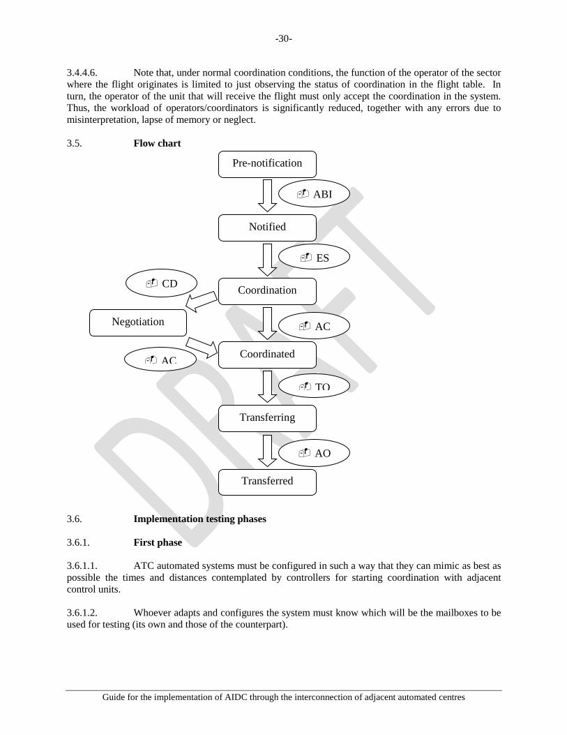
3.4.4.6. Note that, under normal coordination conditions, the function of the operator of the sector where the flight originates is limited to just observing the status of coordination in the flight table. In turn, the operator of the unit that will receive the flight must only accept the coordination in the system. Thus, the workload of operators/coordinators is significantly reduced, together with any errors due to misinterpretation, lapse of memory or neglect. 3.5. Flow chart
3.6. Implementation testing phases 3.6.1. First phase 3.6.1.1. ATC automated systems must be configured in such a way that they can mimic as best as possible the times and distances contemplated by controllers for starting coordination with adjacent control units. 3.6.1.2. Whoever adapts and configures the system must know which will be the mailboxes to be used for testing (its own and those of the counterpart).
Pre-notification
ABI
Notified
ES
Coordination
AC
Coordinated
TO
Transferring
AO
Transferred
Negotiation
AC
CD
-31-
Guide for the implementation of AIDC through the interconnection of adjacent automated centres
3.6.1.3. It should be noted that tests would take place between simulators and all AFTN/AMHS addresses of those control units that will not be affected by the tests must be blocked. For example, the addresses of aerodromes to which take-off messages are normally sent automatically must be removed from the databases. 3.6.2. Second phase 3.6.2.1. A test protocol--covering the widest possible range of cases--will be developed to conduct tests between the two control units, with the participation of technical, database management, and operational personnel. 3.6.2.2. Tests will involve generating FPLs in both control units and verifying that the systems automatically transmit the notification and coordination messages in accordance with the times and distances established in the configuration. 3.6.2.3. It is recommended that the AIDC or TEST designator be used as the aircraft ID (box 07), followed by a test sequence number. 3.6.2.4. In case the CPL modality is used for initial coordination messages, it must be ensured that this message will generate and activate an FPL in the receiving unit if such FPL does not yet exist. 3.6.2.5. The test will also involve verifying the proper operation of acceptance, rejection, and transfer messages, and an analysis of the reasons why the system may be sending or receiving LRM messages. 3.6.3. Third phase 3.6.3.1. Once the previous phase has been successfully completed and the correct exchange of messages between the systems has been verified, operational tests will be conducted with the participation of supervisors, instructors, and controllers of each control unit. 3.6.3.2. To complete this stage, consideration should be given to training of operational personnel on the use of AIDC and its benefits. 3.6.4. Fourth phase
3.6.4.1. Once AIDC coordination procedures have been tested and accepted by the operational personnel, the new letters of agreement will be signed between the control units, incorporating AIDC as
an alternate means of coordination initially, sand subsequently as the main means of coordination.

-32-
Guide for the implementation of AIDC through the interconnection of adjacent automated centres
APPENDIX A
SAM IPV4 REDDIG LAN NETWORK ADDRESSING PLAN BY STATE
1. In order to define the SAM IPv4 addressing plan, address assignments for each State that must and are being applied are listed below.

-33-
Guide for the implementation of AIDC through the interconnection of adjacent automated centres
APPENDIX B
SAM IPV4 REDDIG WAN ADDRESSING PLAN FOR THE INTERCONNECTION BETWEEN STATES
1. In order to define the SAM IPv4 REDDIG WAN addressing plan for serial links for the
interconnection between States, address assignments that must and are being applied are listed below.

-34-
Guide for the implementation of AIDC through the interconnection of adjacent automated centres

-35-
Guide for the implementation of AIDC through the interconnection of adjacent automated centres

-36-
Guide for the implementation of AIDC through the interconnection of adjacent automated centres
-37-
Guide for the implementation of AIDC through the interconnection of adjacent automated centres
-38-
Guide for the implementation of AIDC through the interconnection of adjacent automated centres
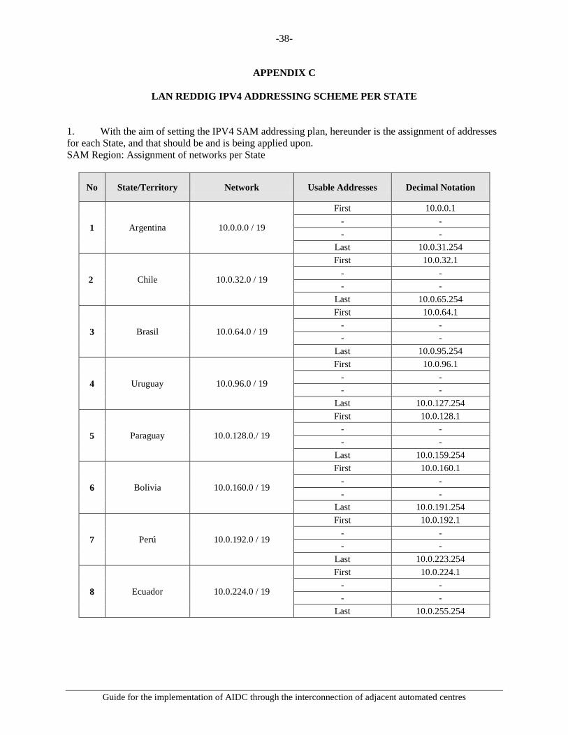
APPENDIX C
LAN REDDIG IPV4 ADDRESSING SCHEME PER STATE 1. With the aim of setting the IPV4 SAM addressing plan, hereunder is the assignment of addresses for each State, and that should be and is being applied upon. SAM Region: Assignment of networks per State
No State/Territory Network Usable Addresses Decimal Notation
1 Argentina 10.0.0.0 / 19
First 10.0.0.1 - - - -
Last 10.0.31.254
2 Chile 10.0.32.0 / 19
First 10.0.32.1 - - - -
Last 10.0.65.254
3 Brasil 10.0.64.0 / 19
First 10.0.64.1 - - - -
Last 10.0.95.254
4 Uruguay 10.0.96.0 / 19
First 10.0.96.1 - - - -
Last 10.0.127.254
5 Paraguay 10.0.128.0./ 19
First 10.0.128.1 - - - -
Last 10.0.159.254
6 Bolivia 10.0.160.0 / 19
First 10.0.160.1 - - - -
Last 10.0.191.254
7 Perú 10.0.192.0 / 19
First 10.0.192.1 - - - -
Last 10.0.223.254
8 Ecuador 10.0.224.0 / 19
First 10.0.224.1 - - - -
Last 10.0.255.254

-39-
Guide for the implementation of AIDC through the interconnection of adjacent automated centres
No State/Territory Network Usable Addresses Decimal Notation
9 Colombia 10.1.0.0 / 19
First 10.1.0.1 - - - -
Last 10.1.31.254
10 Venezuela 10.1.32.0 / 19
First 10.1.32.1 - - - -
Last 10.1.63.254
11 Guyana 10.1.64.0 / 19
First 10.1.64.1 - - - -
Last 10.1.95.254
12 Surinam 10.1.96.0 / 19
First 10.1.96.1 - - - -
Last 10.1.127.254
13 Guyana Francesa (Francia) 10.1.128.0 / 19
First 10.1.128.1 - - - -
Last 10.1.159.254
14 Trinidad y Tobago 10.18.96.0 / 19.
First 10.18.96.1 - - - -
Last 10.18.127.254
15 Vacante 10.1.160.0 / 19
First 10.1.160.1 - - - -
Last 10.1.191.254

-40-
Guide for the implementation of AIDC through the interconnection of adjacent automated centres
APPENDIX D
COMPOSITION OF ATS MESSAGES
ATS message fields
Field Element (a) Element (b) Element (c) Element (d) Element (e)
03 Message type designator
Message number
Reference data
07 Aircraft identifier SSR mode SSR code 09 Number of aircraft Aircraft type Wake
turbulence category
10 Radio communication and navigation and approach aid equipment and capabilities
Surveillance equipment and capabilities
13 Aerodrome of departure
Time
14 Control point Time at control point
Cleared level Supplementary data Conditions
15 Cruising speed Cruising level Route 16 Destination aerodrome Total estimated
elapsed time Destination alternates
18 Other data 22 Field indicator Modified data 31 Facility designator Sector
designator
32 Time Position Trace ground speed
Trace heading Reported altitude
FPL (filed flight plan)
FPL field Required elements Optional elements Comments
03 a. b. 07 a. b. c. The SSR code is sent
only if one has already been assigned and the aircraft is equipped for it.
08 a. b. Element (b) is included if so required by the boundary agreement.
09 b. c. a. 10 a. b. 13 a. b. 15 a. b. c. 16 a. b. c.

-41-
Guide for the implementation of AIDC through the interconnection of adjacent automated centres
FPL field Required elements Optional elements Comments
18 a. Other information Element (a) is included only if no other information is provided. Any element (a) or other information (but not both) should be included.
ABI (reporting message)
ABI field Required elements Optional elements Comments
03 a. Element (c) shall contain the reference number of the first message sent for this flight.
07 a. b. c. If an SSR code has been assigned, it must be included.
13 a. 14 a. b. c. d. e. 16 a. 22 CPL (current flight plan)
CPL field Required elements Optional elements Comments 03 a. b. 07 a. b. c. The SSR code is only
sent if one has already been assigned and the aircraft is equipped for it.
08 a. b. Element (b) is included if so required by the boundary agreement.
09 b. c. a. 10 a. b. 13 a. 14 a. b. c. d. e. 15 a. b. c. 16 a. 18 a. Other information Element (a) is included
only if no other information is included. Any element (a) or other information (but not both) must be included.

-42-
Guide for the implementation of AIDC through the interconnection of adjacent automated centres
EST (estimates)
EST field Required elements Optional elements Comments
03 a. b. c. Element (c) shall contain the reference number of the last message sent for this flight.
07 a. b. c. The SSR code is sent only if one has ben assigned and the aircraft is equipped for it.
13 a. The aerodrome of departure must match the value previously sent in the FPL or the last CHG that modified the FPL.
14 a. b. c. d. e. 16 a. The destination
aerodrome must match the value previously sent in the FPL or the last CHG that modified the FPL.
CDN (coordination message)
CDN field Required elements Optional elements Comments 03 a. b. c. 07 a. b. c. 13 a. b. 14 a. b. c. d. 16 a. ACP (acceptance message)
ACP field Required elements Optional elements Comments 03 a. b. c. 07 a. b. c. 13 a. b. 16 a. RJC (rejection message)
RJC field Required elements Optional elements Comments 03 a. b. c. 07 a. b. c. 13 a. b. 16 a.

-43-
Guide for the implementation of AIDC through the interconnection of adjacent automated centres
TOC (transfer of control message)
TOC field Required elements Optional elements Comments
03 a. b. c. 07 a. b. c. 13 a. b. 16 a. AOC (assumption of control)
AOC field Required elements Optional elements Comments 03 a. b. c. 07 a. b. c. 13 a. b. 16 a. LAM (logical acknowledgment message)
LAM field Required elements Optional elements Comments
03 a. b. c. LRM (logical rejection message)
LRM field Required elements Optional elements Comments
03 a. b. c. 18 Text as shown in the
comments Describes the error code:
after RMK /, includes two digits for the error code.

-44-
Guide for the implementation of AIDC through the interconnection of adjacent automated centres
APPENDIX E
LIST OF ACRONYMS
ABI Advance Boundary Information (AIDC message) ACC Area Control Centre ACP Acceptance (AIDC message) ADS Surveillance ADS-C (AIDC message) ADS-B Automatic Dependent Surveillance - Broadcast ADS-C Automatic Dependent Surveillance - Contract AFTN Aeronautical Fixed Telecommunications Network AIDC ATS Interfacility Data Communications AMHS Aeronautical Message Handling System AMHS ATS Message Handling System AOC Airline Operational Control; or Assumption of Control (AIDC message) APP Approach Control Office ASCII American Standard Code for Information Interchange ASIA/PAC Asia/Pacific ATC Air Traffic Control ATM Air Traffic Management ATN Aeronautical Telecommunications Network ATS Air Traffic Services ATSU Air Traffic Service Unit CAAS Common AMHS Addressing Scheme CARSAM Caribbean – South America CCAM Centro de Conmutación Automática de Mensajes (Automatic message switching
centre) CDN Coordination (AIDC message) CH AFTN Channel CHG ICAO Modification Message CNS Communications, Navigation, Surveillance CPDLC Controller Pilot Data Link Communications CPL Current Flight Plan (AIDC message) DS Directory server that communicates using X.500 protocols DS Directory Service EST Coordination Estimate (AIDC message) FPL Filed Flight Plan IA-5 International Alphabet 5 ICAO International Civil Aviation Organization ICD Interface Control Document IP Internet Protocol IPM Inter Personal Message IPv4 Internet Protocol version 4 IPv4 REDDIG SAM IP addressing plan, version 4. Uses the REDDIG and corresponds to the SAM
Region ITA-2 International Telegraph Alphabet No. 2 LAM Logical Acknowledgement Message (AIDC message) LRM Logical Rejection Message (AIDC message) MS Message storage for handling message delivery and retrieval

-45-
Guide for the implementation of AIDC through the interconnection of adjacent automated centres
MTA Agent responsible for routing messages between MTAs, MSs and MTAs Message Transfer Agent
MTCU Message Transfer and Conversion Unit NAT Network Address Translation NAT: IP address translation protocol OSI Open System Inter-connection P1 Protocol for communicating and routing messages between MTAs (ITU-T X.411) P3 Delivery protocol (“pull”) P7 Protocol for the UA to withdraw from MS (ITU-T X.413) (“push”) REDDIG South American Digital Network REDDIG LAN Environment associated to the regional IP addressing plan for each State REDDIG WAN Environment associated to the regional IP addressing plan for interconnection
between States REJ Rejection (AIDC message) Speech ATS Speech circuit for ATS communications TCP Transfer of Control Point TOC Transfer of Control (AIDC message) TWR Aerodrome control tower UA User Agent UTC Universal Coordinated Time

![Local Single Sky ImPlementation (LSSIP) ROMANIA · or services to the Internet Protocol (IP) [IDP] * COM10 Migrate from AFTN to AMHS * COM11 Implementation of Voice over Internet](https://img.pdfslide.net/doc/110x75/5eda3c98b3745412b57100d3/local-single-sky-implementation-lssip-romania-or-services-to-the-internet-protocol.jpg)