Embed Size (px)
Citation preview
GUIDE
FOR THE PREPARATION OFPROPOSED TECHNICAL APPROACHES
(PTA)
401-
FIATI
PUBLISHED BY THE DIRECTION OFTHE CHIEF OF NAVAL MATERIAL t
FEBRUARY 1966THIS 0WOM HAS OEn APPRFOR PUBLIC KEuEm, ALmg
NAVMAT P3910ACLEAR INGHOUSE
r r I V-
• 1

BestAvai~lable
copy

Sr1.1
ABBREVIATIONSADO Advanced Development ObjectiveAPP Advance Procurement PlanASN(R&D) Assistant Secretary of the Navy (Research and Development)BUPEllS Bureau of Naval PersonnelBUSHIPS Bureau of ShipsBUIWEPS Bure-na of Naval WeaponsOD Contract DefinitionOF Concept FormulationONM Chief of Naval MaterialONO Chief of Naval OperationsONP Chief of Naval PersonnelCOMOPTEVFOR Commander. Operational Test and Evaluation ForceCOSAL Coordinated Ships Allowance ListDONO(D) Deputy Chief of NavaI Operations (Development) (Op--0?)DDR&E Director of Defense Research and EngineeringECM Electronic CountermeasuresECOM Electronic Counter CountermneasuresEDR Exploratory Development RequirementsFYFS&FP Five Year Force Structere and Financial ProgramGOR General Operational RequirementMPE Monthly Progress Evaluation
MTBF Mean Time Between FailuresMTTR Mean Time To RepairNAVMAT Office of the Chief of Naval MaterialNEC Navy Enlisted ClassificationNMSN Naval Material Support EstablishmentNOBO Navy Officers Billet CodeNRR Navy Research RequirementsNTDS Naval Tactical Data SystemOMN Operation and Maintenance, NavyOPN Other Procurement, NavyOPNAV Office of the Chief of Naval OperationsOSD Office of the Secretary of DefensePOP Program Change ProposalPDA Principal Development ActivityPDP Project Definition PhasePMP Project Master PlanPERT Perfornance Evaluation Review TechniquePTA Proposed Technical ApproachRDT&H Research, Development, Test and EvaluationUFI Radio Frequency InterferenceSCN Shipbuilding and Conversion, NavySECNAV Secretary of the NavySOR Specific Operational ReqluirementSTINFO DoD Scientific and Technical Information ProgramTDP Technical Development PlanTEOCHVAL Technical EvaluationTSOR Tentative Specific Operational RequirementWBS Work Breakdqwn Structure
C5
. :
'1 1

tII i
C
I:I
I
= -, Ii*I
-� -I I
IIi
12
GUIDEFOR THE PREPARATION OF
PROPOSED TECHNICAL APPROACHES(PTA)
=j
PUBIUE BY THE DIRECTIN OFTHE CHIE F NAVAL MATERIAL
2EBRUARY 1966THIS DoCUMENT HAS BEEN APPROVED iFOR PUBLIC RELEASE AND SALE;ITS DISTRIBUTION IS UNLIMITED NAVMAT P3910A
_ .2

TABLE OF CONTENTS
Inzoue-o ---- XhopssTechical Appoahat Toast ............... zi
Uetio 1. foreword ----------------------------- 1-1t, Oaepo ............................ 2-i
. Opadoma Diagrm -------------.-.---.-.---------- ...........- -i4. ] aek Diagram --------------------------------------------- -- -- -1L. 0t, Time, WnW Pedormaanc Envelopes ----------------------------- 5-16. Degee of RIsk ............................................. ------- 4-17. CoMP.Utbl ty ............................................. ------- 7-1& manpower Oonberatloa --------------.---.------................. -1t. Udh1abflQty a" Malntainability ............................. ------- 0-1
1i6 Itumm*T*7404 R*0 omm4Uon ------------------------------------ 10b-111. sthorq es -------------------------------------------------------- 11-1A A ppe fdl (e ) ............................................ -------- 1 ,-1
Appead A. Cmumnt OPNAVINST of the 8910. Serie"* ------------------- - A-13. TDP Qfi4l--Seetion 7, Block Diagram -......................- -i 0CL TO? Goid16-Sactica 10, Reliability a&W Maintainability Plan 0-1
* Proncipal Development Activtiese s•ould fusert a copy of the uene t edition ofOPNAVINST P010.8 4erls as Appenlx A to this guide.
fCf
IUST OF ILLUSTRATIONS
I The Stepe In yte't Development ------------------------------ ----------- To2 Sample PTA Cover Sheet ------------------------------------------------- lot8 Bample VXA Table of Contents -------------------------------------------- Xitt4 intormatlon nlow In Gemeration of PTA'o ---------------------------------- ITV'yl
3 -
AS
For sale by the Srperlntendent of Documents, U.S. Government Printing Omffce
Washington, D.C. 9040
Price $150
. . ...i_ ,
RECORD OF CHANGES
CHANGE DATE OF DATE eYNO. CHANGE ENTERED WHOM ENTERED
C'
ivI
F!
INTRODUCTION
GeneralThe purpose of this guide is to provide guidelines for the preparation of
Proposed Technical Approaches (PTA) documents and an explanation of theneed for the information required therein. It is intended for use by all whohave an interest in the preparation and review of PTA's. It is a companion tothe "Guide for the Preparation of Technical Development Plans (TDP)"(NAVMAT P8910) published by direction of the Chief of Naval Material(CNM). It is analogous to the TDP guide in that it is intended as a gu. .3rather than an inflexible set of rules. However, adherence to the general scopeand intent of the suggestions provided herein should provide responsive andeop•,,,: d Coouments including all of the informnation usually requiredin a PFA. Each section of this guide is organized in accordance with theinstructions for PTA preparation described in OPNAVINST 8910.8 Series.A check list is found at the end of each section which emphasizes the majorpoints which should be covered in the corresponding PTA section.
Attention is invited to the Handbook for the Preparation of ProposedTechnical Approaches (PTA) (NAVMAT P3910A SUP-i) which containsmore detailed guidance for individuals engaged in PTA preparation.
Description and Purpose of PTAA PTA document presents alternative approaches for a system or com-
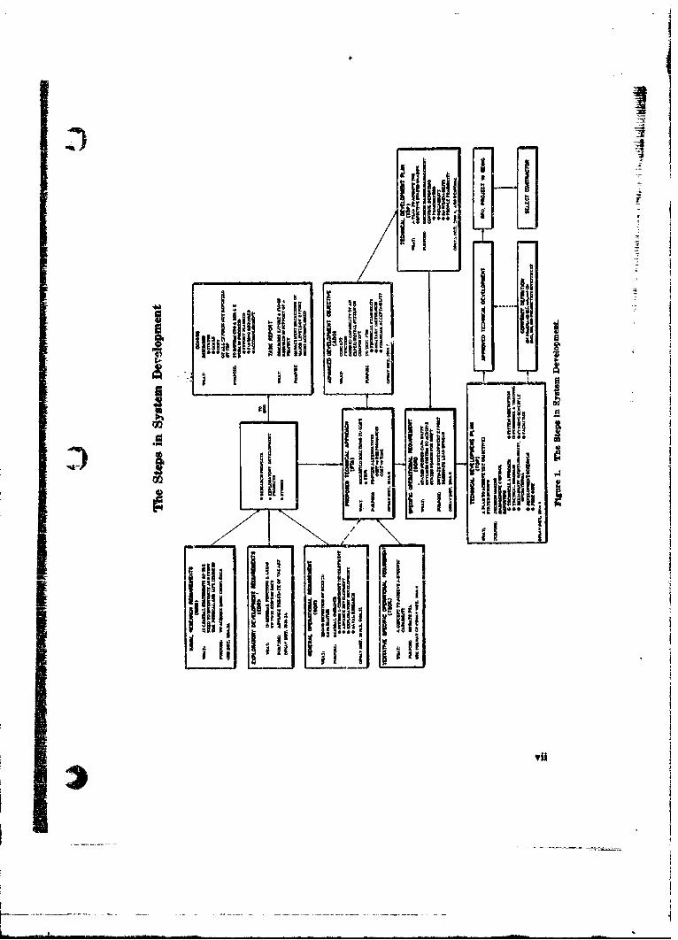
ponent concept stated or implied in a General Operational Requirement(GOR). PTA's are prepared for the Chief of Naval Operations (CNO) bythe Naval Material Support Establishment (NMSE) or other offices or bu-reaus, either as a required response to a Tentative Specific Operational Re-quirement (TSOR) or voluntarily in response to a GOR. Both the GOR andthe TSOR are promulgated by CNO. An explanation of the purpose andrelationship of the various Research, Development, Test, and Evaluation(RI)T&E) requirements and reporting documents is contained inOPNAVINST 3900.8 Series. Figure 1 depicts the sequence of evolutionaryst-eps ,. .- ..in .systeis dcvelopm.ent and the place that the PTA and otherofficial documents occupy in the process. Voluntarily submitted PTA's maybe submitted at any time, while those responsive to a TSOR are due within90 days of the date of the TSOR. However, the CNO is not bound in any wayto respond to a PTA with an ADO or SOR.
The Marine Corps independently develops requirements for materialwhich is used primarily for its own missons. Although the greater number ofPTA's, by far, will be generated for missions under the purview of CNO, thecontents of this guide are fully applicable to PTA's addressing Marine Corpsrequirements.
V
IR
A PTA serves four needs:a. It provides a formal meaws by which new technology is introduced into
naval warfare systems.b. It presents certain technical and financial informatibn to the CNO
on which to bae a decision to commence a development program;therefore;
c. It provides technical and financial information necessary for prepara-tion of a Specific Operational Requirement (SOR), or Advanced De-velopment Objective (ADO) an appropriate.
d. It provides the initial estimates of development and production costsin or-er to determine whether a formal Contract Definition will berequired. In the event the proposed development appears to meet thecriteria for Contract Definition, the PTA will be a neceosary step inmeeting the prerequisites for Contract Definition.
A PTA normally contains a description of the problem to be solved withreference to the pertinent GOR or TSOR, and includes a functional descriptionof each alternate system or component concept as well as a diagram of typicaloperational usage and a functional flow diagram of included sub.systems andassociated systems It discusses operational effectiveness in terms of perform-amhe, reliability, operability, and maintainability. It contains trade-off analysesof the various alternative approaches in terms of electiveness, developmenttihe and cost. It includes a recommendation as to the BDT&E Category underwhich the development should be pursued as well as to the preferred technicalapproach of the several presented. In addition, for management planning, Cthe PTA contains a preliminary schedule of major milestones of developmentshown in time sequence and an estimate of funds needed each year. Personnelimplications of propoeed systems are addressed as well.
Impertant* of PTA
Since the PTA is the initial Research and Development document whichforecasts procurement workload in R&D, it is of considerable concern to pro-oureamnt planners In all probability, the personnel implications of a propoeedsystem will be addressed for the first time in the PTA proposing the system.A PTA is often used as a selling document for a development that the origi-nating organization considers worthwhile. As such, it is in competition withmany other demands for dovelopment money. In general, the better the PTAthe more it will cost to produce. However, the relative expensiveness of thePTA must be considered in relation to the desire to "sell" the dtilopmentaklres•.
vi
Ilk'Iht i 7.
SI l " I 9• " i ii~ iN I' i
kil
II i •1i i I
Itt

Submittal of PTA's
The PTA documents are forwarded to CNO via CNM. Organizationswithin the NMSE are encouraged to submit PTA's vohlutarily in responseto a GOR. Naturally, all such PTA's do not lead to issuance of an SOR orTSOR, at least on their initial submission. As more is learned, PTA's maybe updated and resubmitted. To expedite the review of resubmitted PTA's,the nature of the change should be indicated in the forwarding letter and thedocument itself. This should be done in the document by indicating a revisiondate on the cover sheet and inclusion of an "Index of Effective Pages" similarto that used in a TDP.
Experience to date with processing documents including PTA's has dem-onstrated that. CNM approval can be expedited by informal consultationbetween the Principal Development Agency (PDA) and NAVAIAT duringthe dm-ft copy ttage.
"Advance Copies"
As a general rule, "advance copies" should not be circulated outside (heNMSE and designated support activities before review ahd approval by CNM.This is not i-atwided to interfere with the free interchange of inionnationbetweeD the Material Bureaus and OPNAV. However, embarrassing situationsand unnieessary added workload for CNO can result from free circulation of"documents which may not be subsequently approved by CNML When spe-cifically requested by higher authority, a draft copy of a PTA may be sub-mitted as back-up data. It should be identified as a draft copy in all corre-spondence and ute of the document, and should display prominently thefollowing information on the cover and title page, "DRAFT COPY, HASNOT BEEN APPROVED BY CNM".
VaritUis In PTA's
The scope of a PTA, and to some extent its tone, will vary according tothe type of requirement document to which the PTA replies, and also to thetype of requirement document that the PTA is expected t, elicit from the
Chief of Naval Operations (CNO). Programs of gkat diversity are sponsored.by the NMXSE resulting in a rather wide variation in PTA documents. Thematurity of 44 development influences the nature of a PTA addressing it. ThePTA for a System concept will ordinarily be different in scope from that ofa PTA for a component or "building block" which may later be combined withother "buildi:ng blocks" to produce a system. The variations possible are die-cussed in the sections which follow.
vili
II
All PTA. do menta speak to a "Base Lane" system or deuce, i.e., ths
system concept or device which serves as the model against which the alterna-tives are to be compared and trade-tffs made. In a PTA responding to aTSOR, the "Bafe Line" system or device is described in the TSOR in terms ofoperational concept, threat to be countered or noncombatant application, de-sired performence characteristics, compatibility requirements and such otherattributes as may be deemed important. The unsolicited PTA, on the otherhand, must postulate this "Base Line" system concept or device. It usuxllyfollows then thf-z the "Base Line" system concept or device presented in sucha PTA is also the one which the preparing activity believes to have most merit.In either case, however, the basic requirement Ior the presentation. in the PTAof alternative approaches must be met.
Establishing User-Producer DialogueComplex systems involve so many individuals and offices on both the user
abd producer sides of the house that serious "language gaps" can develop.Therefore, the user-producer dialogue should be started as soon as possiblein a development so that clear 'hannels of communication can be established.
In particular, increased emphasis on reliability, operability, maintain-ability, etc., has made it absolutely imperative that human factors experts,both in the Material Bureaus and in the Bureau of Naval Personnel, be con-suited during the formulative period of all developments.
Updating of GuideIt is intended that this guide will be periodically revised and updated to
reflect the varied needs of groups within the NMSE.
This publication has been reviewed and approved in compliance -withSECNAVINST 56W0.16.
D oNfDevelopment/Chief of Naval Development
* iiPROPOSED TECHNICAL APPROACHES FORMAT
Enclovure (2) of OPNAVINST 8910.8 Series preser -s a suggested formatfor presentation of the information required for the PTA. It is generallysimilar to thet for a TIP but is somewhat abbreviated and rearranged tobettor 3uit the differet character of the PTA document. The TDP treats asystem which has been singled out for development, while the Proposed Tech-niftl Approaches documnent, rs its name implies, must compare a number of Iapproahes and show trade-ofis in such parameters as effectiveness, cost anddevelo•nm•tt time. Other formats may be used provided that all of the re-quired information it pieaented clearly and there is a good reason for such Ad.Yvimimn. Improved "brochuremanship" is not considered to be a good reason.In cases where a gnit deal of development has been done, the PTA formatmay adhere to the TJ)P format as this will facijtate later transition fromPTA to TDP.
Cover~ Sheet guad Tabl, of Costuets
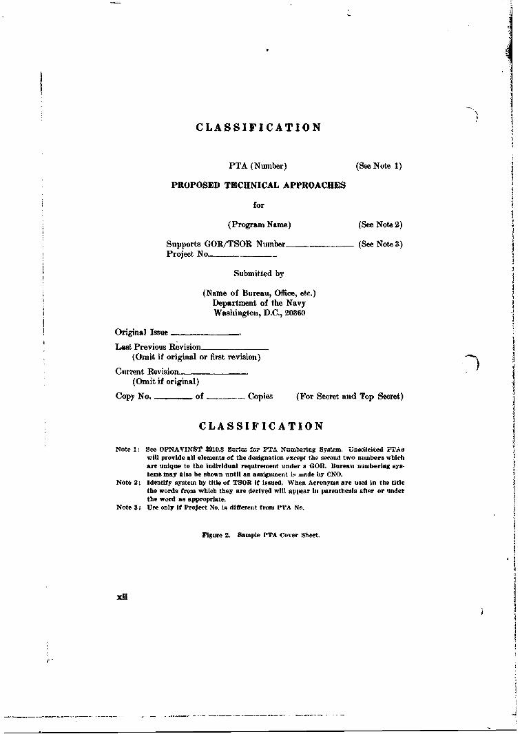
A sample cover sheet containing the required information is shown inFigure 2. It is highly desirable that all covers be uniform so that each PTAcan bI quickUy and curntely identified. Figure 3 shows a sample table ofcontents for two suggwted format.
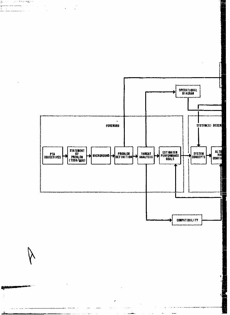
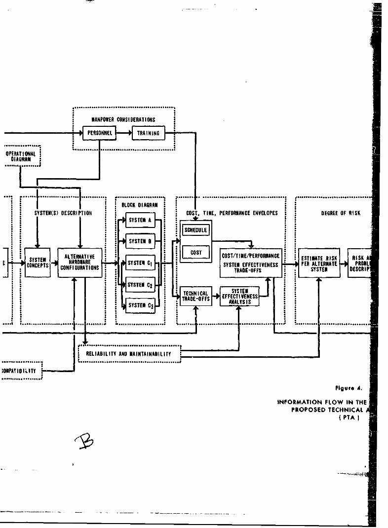
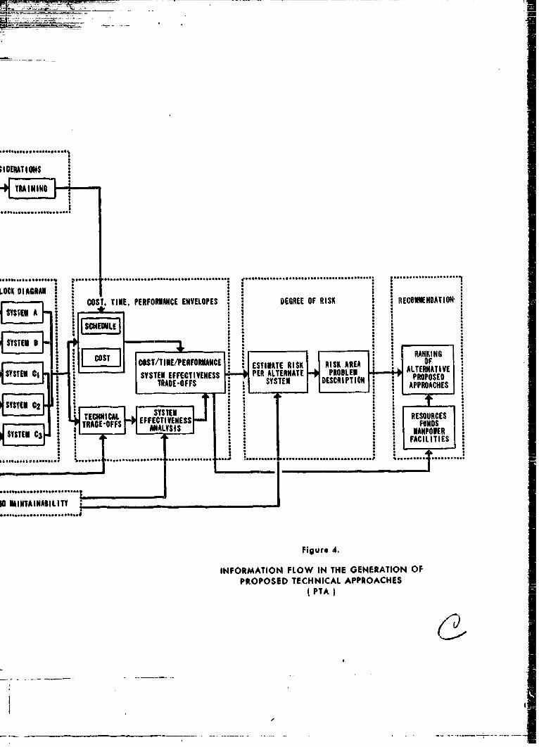
Geutratkau of lmformaalo for PTA
Figure 4 is a. flow ohart showing the sequence of generation of the infor-mation required in the finished PTA.
Format %""tvlty to C ntmtsAs pointed out in the Introduction, the stope and tone of various PTA
documients will differ. However, the bwic informational content and theformat should be essentially the same whether it is solicited or unsolicited,whether it deals with a complete system or a subsystem or lesser element, andregardless of the type o-* r"ponse (ADO, SOR or other directive) soughtfrom CNO. Differenoes in the treatment to accommodate these several cir-
Seumstanas should be in the natum of "slants" brought about by minordifferences in the presentation of the technical material.
X1-
CLASSIFICATION
PTA (Number) (See Note 1)
PROPOSED TECHNICAL APPROACHES
for
(Program Name) (See Note 2)
Supports GOR/TSOR Number (See Note 3)Project No
Submitted by
(Name of Blureau, Office, etc.)Department of the NavyWashington, D.C., 20360
Original Issue
Last Previous Revision(Omit if original or first revision)
Current Revision(Omit if original)
Copy No. - of Copies (For Secret and Top Secret)
CLASSIFICATION
Note 1: See OPNAVJNIST 3010.8 Series for PTA Numbering System. Unsolicited PTAswill provide all elements of the designation except the second two numbers whichare unique to the individual requirement under a GOR. Bureau numbering sys-tems may also be shown until an assignment is muade by CNO.
Note 2: Identify system by title of TSOR it issued. When Acronyms are used in the titlethe words from which they are derived will appear in iarenthesis after or underthe word as appropriate,
Note 3: Uae only if Project No. is different front PTA No.
Figure 2. Sample PTA Cover Sheet.
xUl
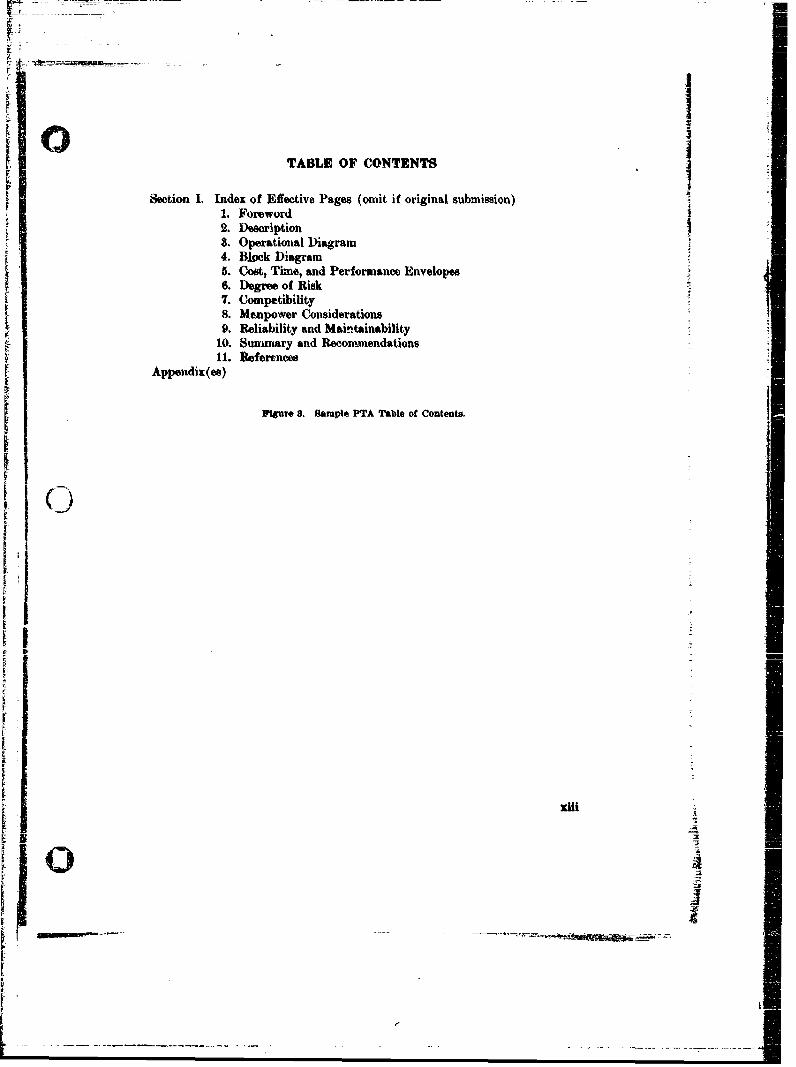
TABLE OF CONTENTS
Section I. Index of Effective Pages (omit if original submission)1. Foreword2. Description3. Operational Diagram4. Block Diagram5. Cost, Time, and Performance Envelopes6. Degree of Risk7. Compatibility8. Mempower Considerations9. Reliability and Maintainability
10. Sunmmary and Recommendations11. References
Appendix(es)
F~gur 3. Sample PTA Table of Contents.
Kiii
Io ; I- c -e--

1'
Philoephy ou Contmt
It is sometimes argued that a PTA document, and particularly the un-solicited, subsystem-or-lesser-component type, need not and sometimes cannotrespond in any way to the area of performance or other general design attri-butes and operational considerations such as reliability, maintainability, opera.bility, compatibility, manpower and training considerations, etc. Although itis conceded that there are instances wherein a discussion on some of thesetopics would be pointless, this should be the exception rather than the rule.It must be remembered that a PTA speaks only to approaches and not designs,and that whereas the worth of these approaches cannot be measured quanti-tatively and in some instances even predicted, a qualitative assessment of theirpotential in these areas must be prmented if the potential user, CNO, or otherreviewing authorities are to be in a position to rule in favor of undertakingthe project. A simple demonstration or postulation of technical feasibilityalone is totally inadequate to support any decision. The fact that somethingcan be achieved in a laboratory does not support a decision to proceed furtherif there is no basis for believing that the attributes against which effectiveness,and hence worth, of a device is to be measured, are not also possible of achieve-ment to an acceptable level. Discussion on these topics, end good, experienced,engineering estimates of the potential inherent in the "Base Line" and alterna-tive approaches, is therefore required.
xiv--
'1
. ...
...... .. I......................................... ............................ ...... ................
FOREWORD SYSTEM(S) DESCR
a: . a
STATEMENT ESTIMATED ALTPTA OF BACKGROUND PROBLE THREAT SYSTEM MA
OBJECTIVES PROBLEM -+DEFINITION ANALYSIS PERFORMANCE 4A4 CONCEPTS(TSOR/GoR)GOS"a a
i •o.0eo~~~~~~~~~~~............Qe ..... o ~.. a.. ml ,...ot....~o - -
...................... ..................
.. ..
•i ~CONPATIDILITY ,. . . . .a
-,a
MANPOWER CONSIDERATIONS
PERSONNEL TRAINING
OPERATIONALDIAGRAM
................ ...........% .... ....................................* .....................
BLOCK DIAGRAM :SYSTEM(S) DESCRIPTION ::I COST, TIME. PERFORMANCE ENVELOPES DEGREE OF RISK
SYSTEM A 2
SYSTEM 0
I • m
ECOOALETERCNATIONSER SYNSTDEMRSEM EFCIEN P
TRD-FSSYSTEM : DETMSCRIK RISKPE SYSTETEM -T
SYSTEM C3
....................... ... . ... ....... " ........................................ ......• ......................
RELIABILITY AND MAINTAINABILITY ________ _______________
........ .................................
:ONPATI1B1L ITY:................
Figuire A.
INFORMATION FLOW IN THEPROPOSED TECHNICAL
(PTA
IDEIATIONS
TRAINING
iCo Cl~ l i lllmiiai•
I * .C ~ tC t* * * .. * * .~ & . . . . .. .. ... ..... .. .. ...... . . . . . . . . . .. . . . .. . ..... ...
.. ................................ %
LOCA 0 1AGRAN tLOST D MCO T, PERFORMANCE ENVELOPES DEGREE OF RISK i CON*,OATIO*
SSVEN A !-- I C *
SYSTEM A 2 i -Y ,
: : 2 2. I ... .. ...... ......4*..... .... .. . ....... .. .. ..... .' " . ... . .... ........
SI*Ti ILT . . ,.
ICOSTIRANKING
COTTNOR INFOMTONFONN HCENRTO OF
* 2 Iwoi~uuc~rniynunq~~ESTIMATE RISK RISK AREA : : OSYT!SYSTEYME EFECIENS PER ALTERNATE PROBLEM ALTERNATIVE
SY ATEM EFFTVNS S * SSE ECITO PROPOSED
TECHNICAL TFCTAPPS RAAOHESOUESANALNLSYSISI MTPOE
I . FACILITIES
S......... ....... T ....... ................
.............10 MAINTAINABILITY ______________ ________
Figure 4.
INFORMATION FLOW IN THE GENERATION OFPROPOSED TECHNICAL APPROACHES
(PTA
SECTION 1
Foreword
1.0 GeneralThis section is one of the moot important in the entire document as it
sets the framework and indicAtes the need for the development. It should,therefore, be most carefully done. It must cover the required informationthoroughly but briefly, making reference to the following sections for details.
1.1 Contet
The Foreword should disclose the nature and extent of the operationalproblem to be solved, and provide such background information as might beavailable and appropriate to assist in developing and evaluating approachesfor its solution. For the PTA solicited by means of a TSOR, most of thisinformation can be provided by the simple expedient of including and ex-tracting the TSOR docunent itself. For the unsolicted PTA, some of thisinformation may be extracted from the GOR, but usually some must also begenerated and provided by the preparer in sufficient detail to establish the
- qualitative/quantitative performance and compability requirements, capa-bilities and attributes of the "Base Line" system or device.
This section should discuss the nature, estent and status of the researchand exploratory development programs supporting the program. This maybe in the form of a historical brief covering the evolution of the programt,. Itshould discuss, in appropriate detail, any and all known foreign and domesticprograms, projects, tasks, etc. w'hich directly or indirectly support or other-wise relate to the project under discussion, and include a statement as to whichof these can be iused in this development. Any major problem areas, as well asproposed or exicting programs for their solution, should be mentioned herewith reference to letails given in hoter sections.
1.2 Considerations Determining Content
It must be constantly kept in mind in this section and those that follow,what response is expected from CNO. The informational content of the PTAmust conform to this. The required contents of the various iequirementsdocuments are included in the following documents: General OperationalRequirement (GOR), OPNAVINST 3910.9 Series; Specific Operational Re-quiroment and Tentative Specific Operational Requirement (SOR and TSOR),
i- OPNAVINST 3910.6 Series; and Advanced Development Objective (ADO),OPNAVINST 3910.7 Series.
S~1-1
I
U1 Need for velopmentIn order to emphalsize the extent of the need for the proposed develop-
ment, the main requirements as posed by the threat (or deficiency) should belisted in a table opposite the eapabilities of existing and planned systems (orcomponente). An analysis of the most significant discrepanoies should bemade. In many eases the systems presently in the fleet will appear verydefloient. It should be remembered that many of these were designed to meet4 lower order threat. Therefore, It is best to quantify suoh deficieneies andalthough they should not be minimized, at the same time, it is more prudentnot to umneoeesarily criticize the present systems.
J
I ___

Foreword Check List
1. Statement of the operational or technical problem to be solved.2. Contains statement of whether the PTA is solicited or unsolicited.S. For solicited PTA:
a. Requirement documnents answering tob. Sununary of requirements
4. For unsolicited PTA:a. GOR answering tob. System or component developmentc. Performance requiredd. Compatibility required
5. Background for developmenta. Foreign and domestic programsb. Studiosc. Exploratory development
1-3

-~~~m p-W ~ nt nt ~-= .~aaz~ll~~
IA
'10
SECTION 2
Description
2.0 Objective and Content
The objective in this section is to tell briefly exactly what is proposed tobe devoloped. For each alternative approach considered, there should be abrief but concise presentation of how it. functions operationally and what itscapability and limitations are seen to be. The temptation to justify or pushany system approach should be avoided in this section, although it may bedesirable to designate a "Base Line" system (or device) against which tocompare other alternative approaches. To clarify the explanations, referencemay be made to the Operational Diagram and Block Diagram which usuallyfollow. This should be a fairly short section since detailed performance andcompatibility considerations will be covered in Iter sections. The most conciseway of depicting this and the method which should be used, is a table com-paring the major requirements posed by the operational threat listed oppositeto the characteristics and cvpabilities of the proposed solutions.
2.1 Considerations for Component Development
For the "Building Block" type of development, there should be a detaileddiscussion of technical problems posed by the several associated operationalproblems, the details of which may be discussed in a more general way thanfor systems designed for specific operational use. This applies only to theunsolicited PTA involving subsystem or lesser component candidates feradvanced development status. It provides insight into the main, and otherattractive operational system applications foreseen for the device. The solicitedtype PTA, on the other hand, replies to a specific operational problem and willnormally be more precise and narrow in scope.
2-1
Description Check List
1. Nature of development.2. Operational function of "Base Line" system and each alternative system.
a. Capabilitiesb. Limitations
3. For component development ("Building Block") unsolicited PTA.a. Technical limitations posed by operational problems.
r: -
SECTION 3
Operational Diagram
The Operational Diagram should be a rather simple drawing showingthe main elements of the system and associated systems being used in an opera-tional environment. It should be carefully conceived and clearly and artis-tically rendered to quickly orient the reader to the usefulness of the proposedsystem.
The Operational Diagram should be labeled using the same terminologyused in the Operational Brief and while it may be explained in the Opera-tional Brief, it should be reasonably self-explanatory.
3-1
)I
-
Omtratlenal MD m Che&k LIst
1. Operational environment clearly depicted.2. Most usual use of development shown.8. Enough information shown to make situation immediately apparent.4. Pictorial quality good.
2-2
i
i
I,-
SECTION 4
Block Diagram
4.0 Purpose
The Block Diagram provides a graphic representation of the essential"Building Blocks", subsystems, equipments, components, and personnel whichconstitute the system (or device) to be developed showing their functionalrelationship, one with another as well as with other associated systems uponwhich the system is dependent for inputs, or which in turn are dependent uponthe system for inputs. This diagram supplements the functional descriptiongiven in Section 2. Operational Brief. Details of interactions with associatedsystems is covered in Section 7, Compatibility.
4.1 Applicable Instructions
The Block Diagram instructions and examples given in the TDP instruc-tion, OPNAV 3910.4 Series, and the TDP Guide are equally applicable forthe PTA. Section 7, Block Diagram, of the TDP Guide is reproduced asAppendix B of this guide.
4.2 Problems with Previous PTAs
Observation of a number of such diagrams, however, has indicated thatthis is perhaps the least understood feature of either PTA or TDP. One ofthe main faults has been an attempt to show too much on one diagram, result-ing in some confusion. More than one diagram can be used when necessary.Only the main interactions of sub-systems and associated systems should beshown. A great many lines running in all directions is very confusing. Sub-systems which normally are combined into a functional unit should be sogrouped in the diagram(s).
4-1
HL
Block Diagram Check List
(See "TDP Check List, Section 7, Block Diagram" reproduced in Appendix B)
1. Representative flow diagram of interaction of major parts.2. Direction of actions and interaction of major parts.8. Major subsystems only in each diagram.4. Only major actions and interactions shown on eah diagram.5. Coa each diagram be rather quickly understood|6. Are interactions in sub-system shown in auxiliary diagrams?7. Are human functions in the system clearly shown?
4-
)-
S
SECTION 5
Cost, Time, and Performance Envelopes
5.0 GeneralThis section is the very heart of the PTA document. Acceptance of a
proposed development is largely determined by its cost, timeliness and effective-ness against an anticipated threat. when compared to competing systemconcepts or device. Novel and improved approaches cannot be justified fordevelopment unless they show a considerable increase in cost-effectivenessover present systems.
5.1 Need for Alternate Approaches
The reason for the present emphasis on approaches is to be found in thecustomary relationship of user and producer. The user (CNO) s more likelyto be satisfied with the product when he can choose front among severala!ternatives supplied by the producer (NMSE). CNO must have and use thisprerogative. He is the expert on operational needs, not CNM or the materialbureaus in the NMSE. The NMSE must provide enough material to allowCNO to choose an adequate technical approach to meet each operationalrequirement.
There are several benefits to be gained from presentation of a numberof technical approaches to the solution of an operational problem. One is theincreased flexibility allo red in making the final choice. Another is that the9-! Material Bureaus by th.ir very nature may see problems in a narrower focusthan does CNO. The Bureaus may see as the best choice that system whichis most refined technically provided its cost is within reason. However, thefinal choice must be made on the basis of many factors; technical, fiscal,political diplomatic climate, personnel ceilings, etc. In the give and take ofbudget apportioning process, it could happen that a very worthwhile bv,.,relatively expensive system would not be chosen for developme nt, whereas,a less costly but only slightly inferior system could be developed to meetthe same requirement resulting in an increase in the overall effectivenessof our forces.
5.2 Basis for Cost Estimates
Cost estimates must be made for life cf the program including RDT&E,production, delivery, installation, operation and support. Also included will Iecosts for personnel research, training equipment, and personnel training costsfor operator and maintenance personnel.
5-1
I)e
5.3 Possible Trade-ofsAlthough the claim is sometimes made that there is only one way that
certain requirements can be met, this view may be based on a lack of effortor a lack of imagination. Even assuming that one can find a requirementfor which only one unique approach is apparent, some trade-offs should bepossible. For example, a given system or equipment may be designed to do -a given job at different levels of performance or reliability (and cost). Ingeneral, the shorter the developmont time allowed, the higher the development.cost. Also, the military worth usually varies somewhat with the introductiondate. It should be abundantly clear that it is impossible to design anythingof real value without consideration of effectiveness, cost and time. In thepast, many of the trade-offs and optimization of design factors have beendone more or less subconsciously by the designer with the various factorsweighted by his own experience. What is now required is that the designfactors, cost factors, development time, and effectiveness based on performanceand military environment may be identified and quantified, that meaning-full trade-offs be made, and that the rationale for optimization be shown,
U4 Sources of DataThe PTA instruction is very lenient in allowing almost any reasonable
source of data down to and including conjecture. An educated guess is con-sidered better than no information at. all. It stipulates, however, that thesource of all data be stated. All assumptions made should be clearly defined.Often, it is possible early in a development to obtain meaningful performanceratios between systems when it is actually impossible to obtain the exactmagnitude of performance of any one system. Therefore, a plea that anydevelopment is in too early a state.to provide trade-offs can hardly be justified.In addition to the sources of background information referred to in paragraph1.1, many other sources of data are available including Navy laboratories,other NMSE organizations, paid contractor studies, and unsolicited contractorpr..ot..o.,•. other. services and '*re5ign developments. Thie Bureau of NravalPersonnel and the Navy Training Devices Center can provide valuable inputson human problems. Some information may be available from the Departmentof Defense Scientific and Technical Information Program (STINFO).
I
i
4
t e DOIDINRT 5100.86, 5129.48 and 5100.38,
5-2
5.5 Contents of Section
This section should discuss subsystem, equipment and component technicalapproaches considered in terms of the parameters (cost, time, performance -4and other attributes including size and weight) which establish their indi- Ividual merit, as well as their potential contribution to the effectiveness (orlack thereof) of both the "Base Line" and alternative systems or device.Responsiveness to, but not necessarily agreement with, the TSOR expressedrequirement in the "Base Line" system or device is inundatory. If, for anyreason, none of the subsystem, equipment, or component technical approachespresented are able to provide any of the qualitatively and quantitativelyexpressed characteristics in the TSOR, this fact should be noted and thedeparture explained. It should provide a comprehensive development andfunding schedule by fiscal years for each subsystem, equipment or componentshown in the Block Diagram of the "Base Line" system, as well as all sup-porting effort that would be requiti in the management of the project.Differences in the time and cost estimates for alternative systems or devicesmay be shown in separate diagrams, or as addenda or modifications to thediagram of the "Base Line" system.
Since time and cost considerations figure largely in the decision makingprocesses attending the entry of a new development project into the FiveYear Force Structure and Financial Program (FYFS&FP), it is essentialthat these factors be realistically assessed and that no elements of cost beoverlooked. Although the estimates presented at this time arm subject tochange when and if ADOs or SORs are issued for the preparation of TDPs,they must not be optimistically represented in order to "sell" the project.
It is imperative that the various comparisons and trade-offs be clearlydisplayed in such a way that differences in design parame', -.:, configuration,physical size, weight, performance, cost, effectiveness, develomeient time, etc.,can be easily and quickly compared. Tables, line charts and" graphs, as wellas pictorial size comparions and other visual displays, should be used whereappropriate. Although detailed explanation of the figures should be foundin the text, they should in general be self-explanatory.
5.6 Other Considerations
There are a number of other considerations which affect the overalloperational effectiveness or overall desirability of a system or development.These considerations inelude the degree of risk, logistics, compatibility,countermeasures, environmental, reliability, vulnerability, maintainability,operability, test and evaluation, training and other manpower considerations.These are covered in the four sections of this guide that follow. Simplicityis an important virtue whiclh must be considered in all future developments.
540
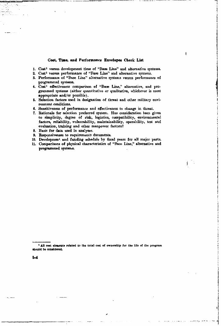
Cost, Time, and Performance Envelopes Check List
1. Coot' versus development time of "Base Line" and alternative systems.2. Cost' versus performance of "Base Line" and alternative systems.S. Performance of "Base Line" alternative systems versus performance of
programmed systems.4. Cost' effectiveness comparison of "Base Line," alternative, and pro-
grammed systems (either quantitative or qualitative, whichever is mostappropriate and/or possible).
5. Selection factors used in designation of threat and other military envi-ronment conditions.
6. Sensitiveness of performance and effectiveness to change in threat.7. Itationale for selection preferred system. Has consideration been given
to simplicity, degree of risk, logistics, compatibility, environmentalfactors, reliability, vulnerability, maintainability, operability, test andevaluation, training and other manpower factors?
8. Basis for data used in analyses.9. Responsiveness to requirements documents.
10. Development and funding schedule by fiscal years for all major parts.11. Comparisons of physical characteristics of "Base Line," alternative and
programmed systents.
All cost elements related to the total coat of ownership for the life of the program
should be considered.
8-4

SECTION 6
Degree of Risk
6.0 GeneralPTA's in the past have sometimes been based on very tenuous data but,
were written in such a way that the fulfillment of the basic requirementseemed practically assured. If this leads to issuance of a SOR, a great dealof difficulty may ensue. CNO must be given as accurate an appraisal aspossible of the prospects for success for the proposed development.
6.1 ContentsIn this section an estimate of the degree of risk involved for each of
the approaches will he presented. In assessing the degree of risk involvedit should be stated whether prinmrily engineering, rather than experimental,effort is required, and whether the technology is sufficiently in hand to proceedwith a systemis development. The principal developmental problems or highrisk areas inherent in the "Base Line" and alternative system approachesunder consideration, should be listed and discussed in their order of impor-tance. For PTAs submitted in support of an ADO oriented project, thissection should also be used to specify the nature and extent of the feasibilityprogram being proposed as well as to specify the end (or decision) pointof the project, with reasons why the specific program and end points werechosen. This is in contrast to a PTA supporting an SOR oriented project, inwhich case the emphasis of this section should he. mostly on at treatment ofthe principal development problem areas.
6.2 Minimizing RiskIt is usually advantageous from the degree of risk standpoint to make
maximum use of existing, proven components, designs and techniques par-ticularly where only marginal improvement cai be obtained fronm newerdevelopments. There are usually advantages, also, in the areas of cost,logistics and personnel training. All such usage should be discussedprominently. 4
6-1
j3
I _
6.3 Dependence on other Developments
The extent to which the success of a particular development hinges uponother developments must be assessed. Where the development addressed ina PTA is to any degree dependent on other programs, the PTA should giveall pertinent available particulars concerning this dependenen, proposelmethods for monitoring progress of the other development, and the possiblecourses to redirect the dependent program should the other program failto satisfy its wants.
6.4 Plans to Meet Exigencies
The PTA should candidly discuss the effect of failure of any particularlydifficult design goal of the development to materialize as planned. Thetrade-offs of possible "fixes" should be addressed.
1
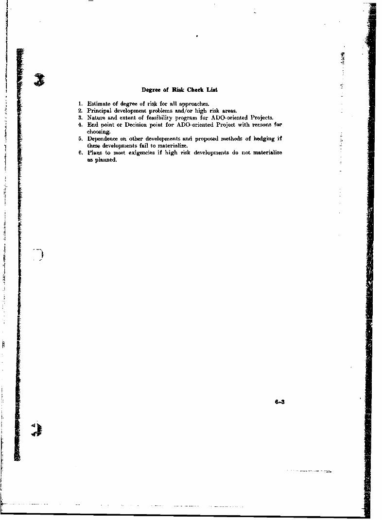
Degree of Risk Check List
1. Estimate of degree of risk for all approaches.2. Principal development problems and/or high risk areas.3. Naturp and extent of feasibility program for ADO-oriented Projects.4. End point or D)ecision point for ADO-oriented Project with rersons for
choosing.5. Dependence on other developments and proposed methods of hedging if
these developments fail to materialize.6. Plans to meet exigencies if high risk developments do not materialize
as planned.
.--
-
S,

SECTION 7
Compatibility
7.0 Equipment Interfaces
The interfaces between the equipment proposd to 1e developed in thePTA and other associated equipment must be defined. Where it is impossibleto concioey define an interface, the program planned to resolve the problemrareas Mhould be described. The current status and cognizant agency of allassociated systems and sub-systems should be indicated in a table. The effect.of as.ociated sub-systems in meeting the systern requirements should bedefined. Steps required to coordinate the new development with cognizantagencies for associated equipments should be discussed. Any significant changein military characteristics of existing ships, vehicles, equipment, or facilitiesshould be indicated.
7.1 Electromagnetic Interference
The proliferation of various equipments using portions of the electro-magnetic energy slectr'am, has made it imperative that each new piece ofequipment or system be critically examined for its posible interaction withother existing or projected usage of the electromagnetic spectrum.' This
must be done at. the earliest, possible time hi the development process for newequipment. Therefore, a PTA for such systems or equipment must addressitself to the problem using all available data. This type of development mustbe coordinated with other services and all other users of the elcctromagneticspectrum. Compatibility also relates to other interface problems such as
space required and available, special support equipment requirements, specialenvironmental requirements, shock and vibration requirements, and otherrequirements such as electrical current, water, steam, ventilation" fuel, etc.Weight may be a problem depending upon where the equipment is to be used.Toxic fumes or dangerous radiation may be produced. All these and manymore must be considered and discussed candidly in the PTA.
I See OPNAVINST 3910.6 Series for Electrical/Eleetronlc Compatibility requIrements.
7-1
'0
7.2 Other Compatibility Problews
In addition to the interface problems already mentioned, the logisticalsupport required by the new development must be considered. The degreeGf susceptibility to couttermeasureo is another area of concern that shouldbe addressed. And perhaps the biggest comp•tibility question of all is justhow wo4l will a new system fit into the overall Navy forces in terms of itsability to support and augment other systems, and how much support doesit require from other systems. When it is designed to fill a gap between othersystems., does it barely do the job or does it overlap the other systems? Inthe came of overlapping systems, is the redundancy useful and desirableoperationally and costwise?
A question of the greatest importance considering the large spectrumof possible combat situations facing the Navy, is the compatibility of thesystem to off-design conditions of operational environment, and the sensitivityof the system's efiectiveness to these conditions which are different fromthose for which the system is optimized.
7-2
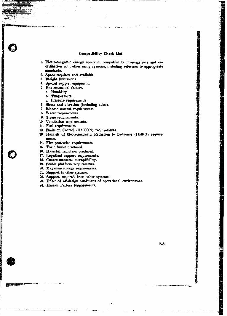
Compatibility Check List
1. Electromagnetic energy Spcctrum compatibility investigations and co-ordination with other using agencies, including reference to appropriatestandards.
2. Space required and available.8. Weight limitations.4. Special support equipment.5. Environmental factors.
a. Humidityb, Temperaturec. Pressure requirements
6. Shock and vibratiun (including noise).7. Electric current requirements.8. Water requirements.9, Steam requirements.
10. Ventilation requirements.11. Fuel requirements.12. Emission Control (EMICON) requirements.13. Hazards of Electromagnetic Radiation to Ordnance (HERO) require-
ments.14. Fire protection requirements.15. Toxic fumes produced.16. Harmful radiation produced.17. Logistical support requirements.18. Countenmeasures susceptibility.
19. Stable platform requirements.20. Magazine storage requirements.21. Support to other systems.22. Support required from other systems.23. Effect of off-design conditions of operational environment.24. Human Factors Requirements.
7-3
S~i
I,
SECTION 8
Manpower Considerations
8.0 GeneralManpower considerations resulting from the introduction of new and
ever more complex systems, have ai, important effect on such systems effec-tiveness factors as reliability, operability, maintainability, and performance.Our modern tools of war must b. designed from the start, taking intoaccount the men who must operate. and maintain them. An optimum systemshould make maximum use of mas capabilities and minimize the effectsof his deficiencies. The human operator and maintainer can be consideredas elements functioning together with machine elements as a total system.
Human factors studies on such subjects as human engineering and per-sonnel and training requirements, should be conducted by specialists in thesematters. Lack of expert consultation in the formulative stage will beapparemt in the PTA. It is strongly advised that the human engineers anddesign engineers of the Principal Development Activity discuss personneland training implications of all PTA's with the Bureau of Naval Personnel(BUPERS).1 (See paragraph 8.6.) Some may require little or no inputfror, BUPERS while others may have very important manpower implications.
8.1 htegration of Manpower Considerations into System DevelopmentEffective systems require that manpower considerations be integral to
system design in all stages of system development. It is recognized that ininitial stages of system conceptualization, human engineering, personnel andtraining considerations are extremely fluid and subject to change. This doesnot negate the requirement for providing such information as can be devel-oped, which will form the basis for more precise research to be carried outas the system design becomes more stable. Manpower considerations shouldbe treated in proper perspective as vital trade-off elements throughout thetotal process of system development.
Additionally, manpower planning must be started at an early point inthe development cycle because of the considerable lead time required forpersonnel planning and implementation. First there must be a determinationof required manning in terms of numbers and skills. Later steps includethe acquisition of personnel suited to the tasks, establishing training centers
'SECNAVINST 5430.67 assigns specifie duties and reoponsibillties for administrationof the Department of the Navy Research, Development, Test and Evaluation (RDT&E)program. See paragraphs 3. .(1)(b), S.e. (1 (e), 31.t(3), 31.t(5), and U.f.(0).
8-1, -
0A
and staffs, compiling training equipment, devices and aids, preparation ofmanuals, and, finally, doing the actual training. Another important reasonfor timely personnel planning is the extreme difficulty, and perhaps impos-sibility, of solving some personnel problems that are not identified until adevelopment has reached a fairly advanced stage.
&2 Hll aa Factors in System Development
.iuman factors refers to a system of thinking and acting which is gearedtowsrd the optimization of the interaction of man and other system com-poir.,ts. This may be accomplished through system design, organization, ]trainimmg, -d the like. Human engineering is the sub-discipline of humanfactors which deals with the specific relationships of man to the hardwareelement, i.e., determination of functions, design, workspace layout, test points,maintainability, etc. Personnel and traizdng research is the sub-disciplineof human factors which deals specifically with examining the human require-m6nts which a given system design, or alternative systems designs, willimpose, and relating these requirements to the Navy's capability to meetthem in terms of quantitative and qualitative criteria, training programs,etc. Persomel and training research, as well as human engineering forproposed weapon and support systems, must begin at. the PTA stage of i isystem development if maximum system performance and r9sliability is tobe achieved.
The objectives of Human Factors Research in system development areas follows:
1. Optimize system performance by ensuring proper mix and matchbetween man and the rest of the system.
2. Ensure the safety and survival of personnel performing in a systemsfrarework.
3. Maximize human motivation and morale.
Requirements to achieve these objectives involve fitting the man to the job trequirements as well as fitting the job to the man, and through research 4and testing determine whether the best "fit" has been obtained.
8.3 Nature of Human Engineering Studies in the PTA Stage
1. Analysis of systems functions that catn or must be performed by man.2. Trade-off studies involving allocation of systems functions between
men and equipment.3. Identify man-machine interfaces including operating and maintenance
consideratiois.4. Analysis of personnel aspects of equipment, procedures, facilities and
environment including life support facilities.5. Performance of overall system.0. Causes of deficiencies in performance.
8-2
-~~ ~ - - ---- -..------.-.--
4A41t
8.4 Purpose and Nature of Personnel and Training Research
Effectiveness of Naval Systems is predicated in part ok. the ability ofthe Navy to meet the ever-increasing personnel requirements &nmanded bythose systems. Numbers available, qualitative distribution, and training re-sources are important constraints on system performance. The Navy hasbeen, and is, faced with a qualitatively distributed manpower shortage. Thisshortage becomes more serious as the state of technological art improves, in
that qualitative personnel requirements become greater, whereas qualitativepersonnel inputs remain relatively constant. Relatedly, the increasing com-plexity of systems strains an already existing training problem.
Basically, personnel and training research answers questionm concerningthe number of people required, the capabilities these people should possess,the time at which such personnel are needed, how they are obtained, fromwhere, how they are organized, training objectives and the requirementsfor their fulfillment, and what the requirements are for testing and evaluationof such personnel. The goal of such an analysis is to match system personneland training requirements wvith existing resources and the euisting Navalpersonnel structure in terms of both capabilities and number of people 1I
required. Personnel and training research and system design are interactingfactors. Changes in design or design concepts may affect personnel andtraining considerations, and conversely, constraints deriving from personneland/or training considerations may require modifications in system design.
"8.5 Objectives of Personnel Research at the PTA Stage
When alternative system approaches have been developed sufficiently to
satisfy information requirements of a PTA, there should be enough informa-tion available to determine initial comparative personnel and training require-ments considerations. The objectives of personnel research at this stage are:
1. To examine the system functions to be performed by man;2. To assess the implications of these functions in terms of the number
of personnel who would be required to fulfill the requirements, thecapabilities that the personnel would have to possess, and the newtraining demands that would ha-ve to be nnet;
3. To relate these requirements to the Navy's ability to meet them;4. To provide a concrete basis for estimating the human resources
feasibility of proposed approaches and for using these estimates assound trade-off criteria in relation to other system parameters;
5. To develop and record information as a basis for subsequent personneland training research.
WI
8.6 Coordination with Bureau of Naval Personnel
The Bureau of Naval Personnel (BUPERS) is sponsoring proceduresto insure the integration of personnel acquisition and training in the planning,design and developnnt p!,hase as w 3li as in the operation and maintenancephase of Naval systems. A close liaisor, is desirable in the PTA stage amongthe human engineers and the system engineers of the Principal DevelopmentActivity, and the research analysts of the New Developments ResearchProgram of DUPERS.
87 Consultation with Naval Training Devices Center
In system developments which appear to involve development of newtraining devices, the Naval Training Devices Center should be consulted.
8.8 Content
Tho PTA provides the first opportunity to examine the manpower inipli-cations of given system approaches. Each approach, therefore, should bediscussed in terms of all available human factors information. Proceduresrequired to provide adequate reliability, operability, maintainability, andsupportability which are related to manpower considerations, should bediscussed.
Information developed as a result of objectives shown in paragraphs8.3 and 8.5 should be included, as should any requirements for retrainingor special training devices. In addition, a narrative summary of HumanFactors RDT&E efforts which will be required during the developmentprograms, the technical data requirements for support of these efforts, anddescription of studies already completed, both in exploratory developmentand in other related programs, should be included.
Typical trade-offs in personnel feasibility of alternative technicalapproaches involve such items as the following:
1. Technically desirable equipment features vs. availability of Navypersonnel to operate and maintain the desired features.
2. Cost reduction features vs. availability of personnel with the requiredskill levels.
3. Time savings vs. personnel skill-level and availability requirements. 44. Use of automated features vs. increased demand for skilled manpower.5. Simplicity of design vs. complexity of operator and maintenance tasks.6. Claimed personnel reduction vs. experimental manning requirements.7. Cost effectiveness considerations vs. morale and retention considerations.
8-4
Ii
--I
Personnel and Training Considerations Check List
1. Qualitative, quantitative peronnel requirements.2. New training demands.3. Personnel and training tradeoff criteria.4. Human resource feasibility of alternative approaches.5. Special training device requirements.6. Human factorti study requirements.7. Operability factors.
I=
)
I
I
_ _ II
�PA�1 I
1�I -
I
I
I
a I
-__-----. -,
-,w••, _ _ - -_ _-
SECTION 9
Reliability and Maintainability
9.0 General
Reliability and maintainability, which are to a great extent interde-pendent, have become probably the greatest problem area in the fleet. To alarge extent reliability and maintainability must be designed into equipmentas it is very difficult to improve either to a marked extent, after a piece ofequipment has been manufactured and installed. Since a piece of equipmentis no more reliable than its least reliable part, very careful considerationof reliability and maintainability of each component must be considered veryearly in the evolutionary process. 'Thie Advanced Development stage isnone too soon.
9.1 ContentsA PTA should contain all information available, either from experimental
work or from similar types of equipment or simply conjecture, as to thereliability and maintainability implications of the proposed approaches. Inaddition, the PTA should discuss those steps which should be taken duringthe development of the various approaches to insure adequate reliability andmaintainability. Special attention will be given to the reliability and main-tainability provisions of the TSOR. Reliability and maintainability goalsand requirements should be defined.
Although it is not expected that the PTA treatment of reliability andmaintainability can be done in the same detail as in a TDP, the same generalrules apply, The closer that it is possible to approach the TDP requirements,the easier it will be later should a TDP be required for the proposed devel-opment. Section 10, "Reliability and Maintainability Plan" from the TDPguide is reproduced in Appendix C as a reference,
9-1
"I.)
H
Reliability and Maintainability Check List
(See "TDP Check List, Section 10, Reliability and Maintainability Plan"in Appendix C.)
1. Analysis of operational problem to establish reliability and maintainabilitygoals or requirements.
2. Analysis of reliability of components and isolation of probable troublespots.
a. Analysis of maintainability of components and determination of possibleproblem areas.
4. Estimation of reliability of components and overall system.5. Estimation of mean time to reyair of components and overall systems.6. Discussion of use environment and its effect on reliability and main-tainability.
7. Source of data used in estimation of reliability, and maintainability.8. Data available along with source and data which should be obtained by
further investigation.9. Rleliability arnd Maintainability assurance program to insure adequacy.
9-2
tI

iISECTION 10
Summary and Recommendation10.0 General
This section is probably (fie most important in the entire PTA and itscontents should he most carefully considered and weighed. Its content-, shouldbe given very wide exposure to all interested parties within the NMSE andother interested offices and bureaus to assure that all possible conflicts areaddressed. Coordination with other services having an interest should be
accomplished.
10.1 Contents
This section states which type of CNO response is sought (ADO--SOR)and under which RIT&E category the development should be pursued. Forthose projects meeting formal Contract Definition thresholds, a brief summaryshould be included of the steps already performed or planned for ConceptFormulation (prerequisite for initiation of Engineering Development) givenin DOD Directive 3200.9 Series. If other PTA's exist or are being producedwhich are related to this PTA, they should be described and the relationshipexplained with a recommendation concerning the several documents as agroup. It should summarize salient points with respect to the performancecapability, military usefulness, financial acceptability, technical feasibility"and timeliness of the various systems and make a recommendation as to the"preferred system from among the various alternative approaches. Estimateddevelopment funding required each year will be presented for the recommendedtechnical approach. Overall program funding implications of the PTAshould be given due consideration; in particular, where other work may haveto be curtailed in order to proceed with the proposed development work.A preliminary schedlule of major milestones in the development programshould be shown in time sequence.
In cases where PTAs must co! ' a number of alternatives to the1B. 6.0 T" •s . ... Sy ,e ;' (I • •°".'.s e.-, to ge- eaiie i e~ dat noa t ,lli~ax
which evalnAtes eatch system conside'ed, against a series of evaluation criteriaselected to achieve a qualitative/quaitl tative presentation of a cost effectiveness
comparison. Such a sheet would be part of this summary,Comment may also be included here of a type which the submitting
Bureau might otherwise include in a transmittal letter to CNM or CNO.This section may be marked by a hard divider or color ('oded for easy
location and access.
10-1
-,4
LT
10.2 C omment on Requirements
The investigations leading to the PTA may indicate desirable deviations
in performance or other characteristics from that given in requirementsdocuments. Any such deviation should be noted here. This applies to toostringent requirements, as well as cases where it is felt that more capabilityshould or could be obtained in the development.
I
I
10-2
t I
Ii-
Summary and Recommendation Check List
1. Response sought from CNO(ADO-SOR).2. Recommend RDT&E Category for development (Advanced Development,
Engineering Development, etc.).3. Related developments and PTA's description and relationship with group
recommendation.4. Summary of performance capability, military usefulness, financial accept-
ability, technical feasibility, and timeliness of various systems.S[ 5. Funding totals by fiscal years for each.
6. Recommend preferred system.7. Overall program funding implications of proposed approaches.8. Explanation of evaluation criteria used for selection of recommended
systems.9. Evaluation matrix showing each system rated against evaluation criteria
explained above. Quantitative and qualitative systems effectivenes shouldbe shown.
10. Additional information of value in selecting optimum system.
-!I ji

• 1
0SECTION 11
References
Reference all documents from which information contained in the PTAwau derived as well as others which would contribute to a more completeunderstanding of the project under discussion.,
1I
11-1
!!-.-!
•. • ISECTION 12
Appendix(es)
When the PTA responds to a requirement document, that requirementdocument should be included in the Appendix.
Any section which threatens to exceed a reasonable number of pages
should be reorganized to enable some or all of the supporting data anddiscussions to be placed in an appendix. No PTA should exceed 30 pages .up to and irncluding Section 10, Sumnmary.
Individual Procurement Feasibility Plans (in structure like an AdvanceProcurement Plan1) shall be prepared for each alternative approach, andincluded as Appendixes to the PTA. These plans should be sufficientlydetailed to provide a basis for:
a. Evaluating the impact of the alternative on procurement.b. Evaluating the economic differences among the alternatives.
'Guidelines for advance procurement planning are found in SECNAVINST 4200.18Series and NAVMATINST 4200.32 Series.
!•-.!
) .•_ • ••-. .
APPENDIX A
OPNAVINST 3910.8 Series
Insert copy of OPNAVr INST 3M10.8 Serieshere in the guide for rýference in preparingPTA's. It does not have tu, be included as partof each PTA.
A- I4
II
-i
Al j
0!
!I
3rAPPENDIX B
SECTION 7
Block Diagram
7.0 GeneralThe purpose of the block diagram is to illustrate in pictorial form, the rela-
tionship between major components of the system and the relationship of thesystem to other systems or functions. In order to be effective it is important tokeep the diagram uncluttered of lengthy descriptions and most titling should bekept to one or two words.
Each major sub-system or function should be shown as a block with its ap-propriate title appearing within the block. To emphasize the importance orphysical size of any function, a larger block than others should be used. Fune-
tions which interface with each other should be connected by lines.Interfaces may take on a number of forms which may be physical, such as
electrical or mechanical interfaces, or non-physical, such as an informationflow. A single line should be used to connect each block which is related toanother block for each type of interface. Connecting lines should be codedon a legend on the drawing and a label placed above the line to describe thecharacteristic of that interface. (Coding should take the form of solid, dottedor dot-dash lines for each type of interface.)
Arrows should be placed on the connecting lines to show the direction ofenergy flow for an electrical or mechanical interface or the direction of data flowfor an informational interface. The point of the arrow should terminate on ablock and arrows on both ends of an interface line signify a two way exchangebetween functional blocks.
The block diagram should be organized so that one can easily find the in-put(s) to the system and follow the flow through the major functions blocks tothe resulting output.To achieve this facility, the block diagram should be constructedl so that the
major line of internal flow runs from the top to the bottom of the page or fromIot to acght. One should avoi , th bloc da shul be cs ted a lAng outl a blc diagram which Mequizre
looping back and forth or up and down io follow the flow through the system.This means that the number of blocks shL uld generally not exceed 0-8.
In de.signing the layout of the block ditagram, it may be that 6-8 blocks donot adequately describe the system in the levelof detail desired by the PDA. Thiscan be resolved by provided subsidiary block diagrams which are drawn on a
functional level which is part of the overall system function. For example,the overall block diagram can have each of its component blocks broken downwith t. sub-system block diagram for each block. This sub-system block dia-gram should be constructed following the same rules as the overall blockdiagram. This process may be repeated as often as desired but it is suggestedthat a maximum of two levels should be employed even for the most complexsystem. ,
B-1
_i
- - A
At times, it may be possible to eliminate the need for a second level of blockdiagram by increasing the number of blocks on the overall block diagram to10 or 12. This practice is perferred since it, results in a single page drawingof the system. Foldout pages can be employed with a maximum size of16 z 10% (a double page).
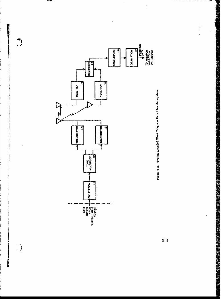
Each block on the overall block diagram should be numbered for reference.Blocks on sub-system block diagrams should be numbered with the numberof the block of the overall block diagram followed by decimal digits. Forexample, the overall block diagram may contain a block labeled "Data Link"and numbered 1.0. If a lo-7er functional level drawing is constructed further jbreaking down "Data Link" each block should be numbered 1.1, 1.2, 1.3, etc.,in the sub-system block diagram.7.1 Overall Block Diagram
The overall block diagram should Le constructed in such a wanner that areviewer of the TDP may quickly ascertain the relationship of the system Jto other systems and the major units of the system under development. Inaddition to following the general guidelines described in SECTION 7.0, themajor flow through the system should be emphasized with a heavy cormcctingline and arrows between blocks existing in the major flow path.
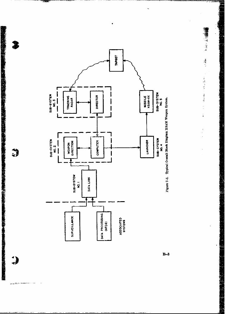
All associated sub-systems should be illustrated as a single block for eachassociated subsystem. Appropriate interface lines should b& shown. Figure7-1 illustrates a Typical Overall Block Diagram.
Included in this section should be a general description of the system opera-tion which follows the flow showA on the overall block diagram. This narrative
should be quite brief and is employed to provide those reviewers who are nottechnically oriented with a general picture of the role of this system in relationto overall DOD objectives and programs. This description shou!d refer tospecific characteristics of the SOR or ADO.
The blocks appearing in this diagram need no, represent physically realiz-able units or systems but may represent functions which involve both equipmentsand human actions. This is particularly applicable in non-automated systemswhere human decision is an integral part of the system operation. The generaldeecript.on of the system operation should include reference to the man-machineinterface and critical points of operator information requirements, informationflow, decision points, stored information, operator intervention and actionalternatives. The overall block diagram should distinguish between equipmentoperation tasks by phase as given in the general description, of the system. Anexample is a command and control system which may be fully automated in thedata acquisition and reaction control functions but may depend upon humanintervention to complete the overall action between acquisition and reaction.7.2 Detailed Block Diagram
This diagram, as stated in SECTION 7.0, is used when ftirther detailing ofthe system's description is required. There may be detailed block diagrams forsome or all of the blocks of the overall block diagram. The degree of detail isa decision to be made by the writer of the TDP and will vary from system tosystem. General guidelines cannot be established to aid in deciding upon the
B--2
,
SLa
2WI Z- I o
•. I I- l U
i g I , Iw
II
(I•a IIL.LJ
:10
to 00
-BJ
W Q.1 _.
4-__-
Im
detail required. However, the detail illustrated in the diagram should relateto the degree of detail employed in SECTION 8, Sub-System Characteristics.That i*, for every block appearing in the block diagram, a portion of SECTION8 shall appear where that block is described.
No descriptive material should be included in this section relating to the de-tailed block diagram since it will appevr in SECTION 8. Figure 7-2 illustratesa Typical Detailed Block Diagram.
B-4t
I
I
M
.-1
SSn- U
6 - -I4 4
x
I �
I)
U
! ii
TDP Check List
SECTION 7
Block Diagram
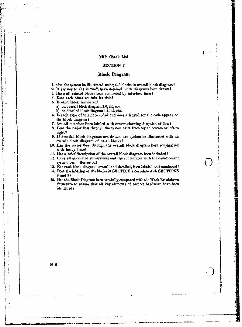
1. Can the system be illustrated using 6-8 blocks in overall block diagramf2. If an.,wer to (1) is "no", have detailed block diagrams been drawnt8. Have all related blocks been connected by interface lines?4. Does each block contain its title-5. Is each block numberedf
a) on overall block diagram 1.0, 2.0, etc.b) on detailed block diagram 1.1,1.2, etc.
6. Is each type of interface coded and does a legend for the code appear onthe block diagram?
7. Are all interface lines labeled with arrows showing direction of flow?8. Does the major flow through the system exist from top to bottom or left to
rightI
9. If detailed block diagrams are drawn, can system be illustrated with anoverall block diagram of 10-12 blocks?
10. Has the major flow through the overall block diagram been emphasized1 with heavy lines?11. Has a brief description of the overall block diagram been includedI12. Have all associated sub-systems and their interfaces with the development
systern been illustrated? C13. Has each block diagram, overall and detailed, been labeled and numbered?
14. Does the labeling of the blocks in SECTIONT 7 correlate with SECTIONS8 and 9q
15. Has the Block Diagram been carefullycompared with the Work BreakdownStructure to assure that all key elements of project hardware have beenidentified?
IE.
-o-ii I
i . . ...-
APPENDIX C
SECTION 10
Reliability and Maintainability Plan j10.0 General
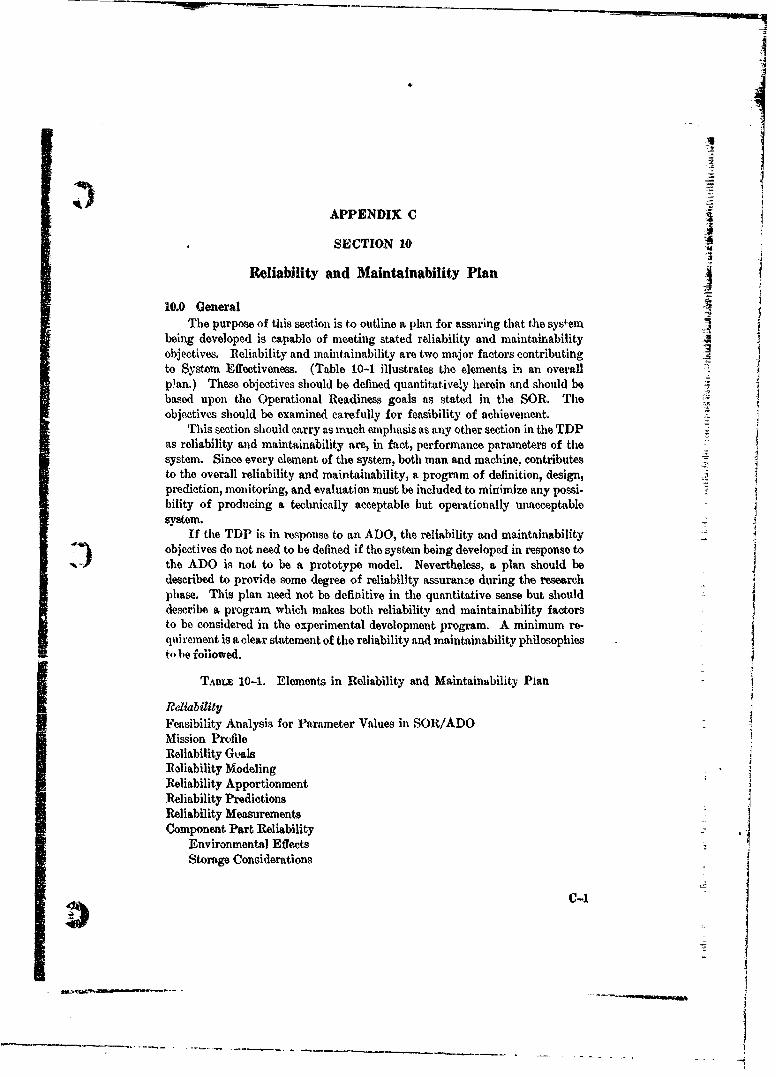
The purpose of this section is to outline a plan for assuring that the systeml -4being developed is capable of meeting stated reliability and maintainabilityobjectives. Reliability and maintainability are two major factors contributingto System Effectiveness. (Table 10-1 illustrates the elements i. an overallplan.) These objectives should be defined quantitatively herein and should bebased upon the Operational Readiness goals as stated in the SOR. Theobjectives should be examined carefully for feasibility of achievement.
This section should carry as much emphasis as any other section in the TDPas reliability and maintainability are, in fact, performance parameters of thesystem. Since every element of the system, both man and machine, contributesto the overall reliability and maintainability, a program of definition, design,prediction, monitoring, and evaluation must be included to minimize any possi-bility of producing a technically acceptable but operationally unacceptablesystem.
If the TDP is in response to an ADO, the reliability and maintainabilityobjectives do not need to bb defined if the systemn being developed in response tothe ADO is not to be a prototype model. Nevertheless, a plan should bedescribed to provide some degree of reliability assuranwe during the researchphase. This plan need not be definitive in the quantitative sense but shoulddescribe a program which makes both reliability and maintainability factorsto be considered in the experimental development program. A minimum re-qui rement is a clear statement of the reliability and maintainability philosophiesS~t- bo followed,
TrALE 10-1. Elements in Reliability and Maintainability Plan
ReliabilityFeasibility Analysis for Parameter Values in SOR/ADOMission ProfileReliability GkqlsReliability ModelingReliability ApportionmentReliability PredictionsReliability MeasurementsComponent Part Reliability ,
Environmental Effects _
Storage Considerations
c-1
.p1

Feasibility Analysis for Parameter Values in SOR/ADOMaRntairability GoalsMaintainability Modeling
Allocation of Repair Responsibilitiest Predictions
Nor:Therefeoeeeths spelytion sholefineplnts for bthe syseliabiwlt andt mahintan
ability assurance. Each plan should indicate the steps to be followed, tihegeneral techniques or specifications to be applied, the major milestones inl tihe
program and the responsible parties charged with establishment of goals andmonitoring of progress toward these goals. The plan should include a reportingmethod to be imposed upon contractors in support of the plan. The quantitativeobjectives for reliability and maintainability for each sub-system should bestated as well as the overall system performance in all of its operating modes.K •It is recognized that quantitative objectives may not be available for some sys-tems under advanced development, for those systems assumed quantitative
"[ - objectives should be provided.The overall availability of the final system i3 a function of its quantitative
reliability expressed as Mean Time Between Failure (MTBF), and its quanti-t ttive maintainability expressed as Mean Time To Repair (MTTR). Becauseof this relationship and because of the ultimate interest of the operating forcesin System availability, the PDA should define plans for reliability and main-tainability assurance which complement each other in such a manner as toinsure the achievement of the overall availability objective.
10.1 Reliability Assurance
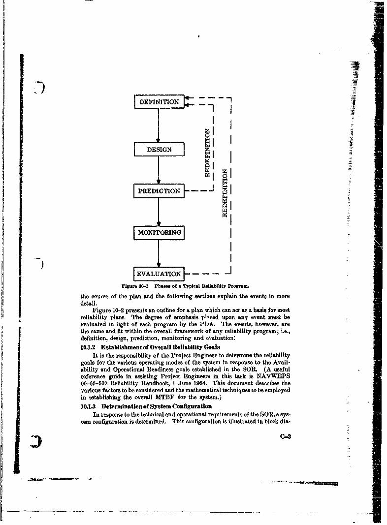
10.1.1 Reliability PlanFig-d A I b-- t "........ the mnajor phas of a reliabiity program. In the
detailed reliability plan Che Project Manager must describe the procedures andtechniques to be employed during each phase of the reliability program.
Furthermore, one must make certain decisions which will be reflected in the
TDP in regard to which phases of the reliability program may be downgradedand which may be emphasized in the particular reliability plan being appliedto the system.
Prior to establishment of a detailed reliability plan, the PDA must answerthe following questioi,: "Is reliability prediction an adequate technique forassurance of reliability or will a reliability demonstration be required?" Theanswer to this question will establish the overall philosophy of the reliabilityplan and a number of important factors should be weighed when consideringthe question.
To evaluate these factors, it is best to examine a typical reliability plait asillustrated in Figure 10--2. The figure illustrates major events occurring in
C-2
AT
[ DESIGN tI
I
IDEINTION -J--~
I jj
SI
Figure 10-1. Phases of a Typieal Reliability Program.
the couese of the plan and the following sections explain the events in moredetail.
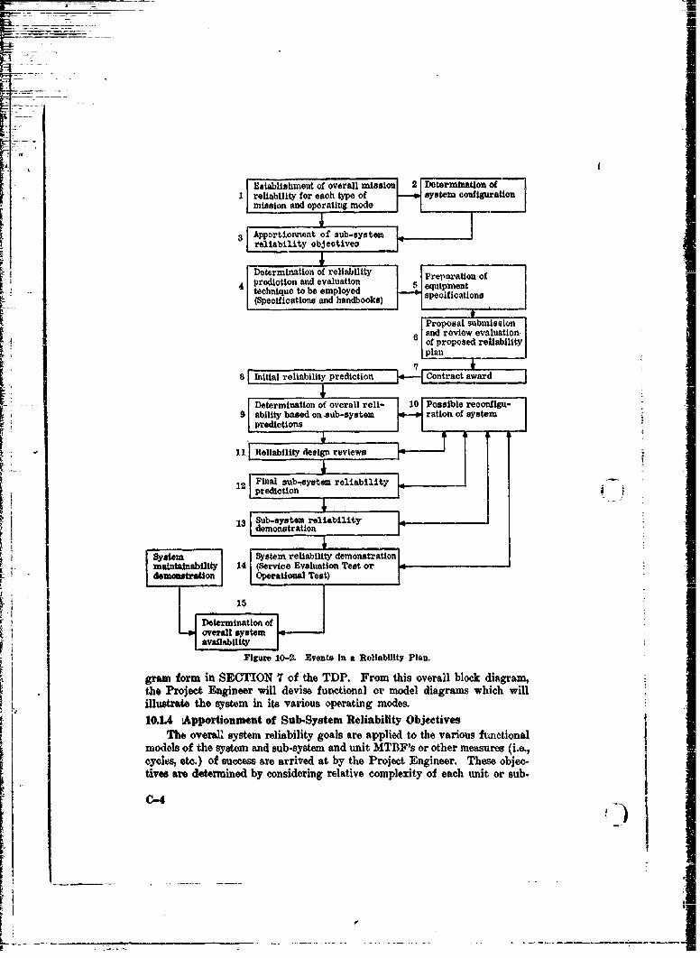
Figure 10-2 presents an outline for a plan which can act as a basis for mostreliability plans. The degree of emphasis plceed upon any event must be"evaluated in light of each program, by the PDA. The events, however, arethe same and fit within the overall framework of any reliability program; i.e.,definition, design, prediction, monitoring and evaluation:10.1.2 Establishment of Overall Reliability Goals
It is the responsibility of the Project Engineer to determine the reliabilitygoals for the various operating modes of the system in response to the Avail-ability and Operational Readiness goals established in the SOR. (A usefulreference guide in assisting Project Engineers in this task is NAVWEPS00.-65-502) Reliability Handbook, 1 June 1964. This document dec.ribes thevarious factors to be considered and the mathematical techniques to be employedin ,astablishing the overall MTBF for the system.)
10.1.3 Determination of System ConfigurationIn response to the technical and operational requirements of the SOR, a sys-
tern configuration is determined. This configuration is illustrated in block dia-
1_
_ _ _ _ _ _ _
-U
Esalsmn fovrl ns1n 1Dtriaino
K 1reliability for each type of system configuration
SApportionment of' sub-syetn
Determination of reliability &rpration ofr ~~~~ prediction and evaluation eqim t
technique to be employed spofictions(Specifications and hadbk)
[Proposal smbmission_
L and review evaluation.of proposed reliabilityplan ___
8 Initial reliability prediction *-LC~ontract award
Determination of overall reli- 10 Possible reconfligu-V 9ability based on .aub-systea 'ration of system
III Reliability design reviews
12 Final sub-,eystem reliability
131 u-ytmrlaiiy
FSy'stem reliability demonstration
:maintainability 14 (Service Evaluation Test ordemoamtration Operational Test)
I Figure 10-2. Events In a Reliability Plan.
gam form in SECTION 7t of the TDP. From this overall block diagram,the Project Engineer will devise functional or model diagrams which willilustrate the system in& it~s various operating mod"s10.UA Apportionment of Sub-ystem Reliability Objetives
[I The overall system reliability goals are applied to the various funetionalI models of the system and sub-system and unit MTBF's or other measures (i.e.,
cyolos, etc) of success are arrived at by the Project Engineer. These objec-tives are determined by considering relative complexity of each unit or sub.
C-4)
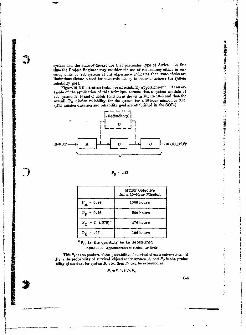
system and the state-of-the-art for that particular type of device. At this
time the Project Engineer may conisidler the use of redundancy either in oir-
cuits, units or sub-systems if his experience indicates that state-of-the-art
limitations dictate a need for such redundancy in order 0~ achieve the system
reliability goal.Figure 10-8 illustrates at techniquo of reliability apportionment. As an ox-
ample of the application of this techniqu~e, assume that a system consists of
sub-systems A, B and C which function as shown in Figure 10-3 and that the
overall, P., mission reliability for the system for a 10-hour mission is 0.95,
(The mission duration and reliability goal are established in the SOR.)
r
I L
I MTBF Objectivefor a 10-Hour Mjosion
~A 0 .9 9 1000 hours
SPC is the quantity to be detervm d~e
Figure 104 Apportionment of Reliability Goals.
This Ps is ,the product of the probability of survival of each sub-system. IfPA is the probability of survival objective for system A, and PD is the proba.
bility qf survival for system B, etc., then Ps can be exprossed as
PS=P.4 ><PZXPQ
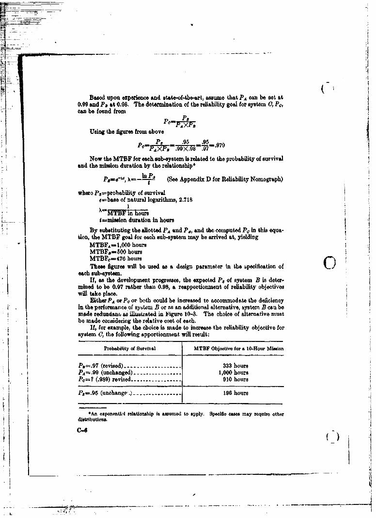
-- !
Based upon experience and state-of-the-art, assume that PA can be set at0.09 and Ps at 0.08. The determination of the reliability goal for system 0, PO,can be found from
PS
Using the figures from above
=PA .. 095 .95
Now the MTBF for each sub-system is related to the probability of survivaland the mission duration by the relationship*
X-----s (Soe Appendix D for Reliability Nomogra'ph)
where Ps=probability of survivals-base of natural logarithms, 2.718
1•MTBF in hour
9mnmisaion duration in hoursBy substituting the allotted PA and P,,, and the computed Pc in this equa-
tion, the MTBF goal for each sub-system may be arrived at, yieldingMTBFA-= 1,000 hoursMTBFP--500 hoursMTBFo=470 hours (7These fWgures will be used as a design parameter in the bpecification of
each sub-system.If, as the development progresses, the expected Ps of system B is deter-
mined to be 0.97 rather than 0.98, a reapportionment of reliability objectiveswill take place.
Either PA or PF or both could be increased to acoommod ate the deficiencyIn the performance of system B or ns an additional alternative, bystem B can bemade redundant as illustrated in k1'gure 10-3. The choice of alternative mustbe made considering the relative cost of each.
If, for example, the choice is made to increase the reliability objective forsystem 0, the following apportionment will result:
Probability of Survival MTBF Objective for a 10-Hour MissIon
Pa---.97 (revised) ------------------- 333 hoursPA=. .99 (unchanged) ---------------- 1,000 hoursPo=? (.989) revised ----------------- 910 hours
Pa=.95 (unchange..) ---------------- 196 hours
*An ezponentW4 relationship is asumed to apply. Specific cases may require otherdistributions.
-.
10.1.6 Determination of Applicable Reliability Prediction and Evaluation
TechniquesIt is at this point that the PDP must decide the answer to the question pre.
viously posed; "Is reliability prediction without evru1uation adequate?"A program of reliability demonstration of necessity will involve increased
program cost and possibly a lengthy testing period. To ne-o-are U1e MTBFof a sub-system or unit with high confidence, the sub-system must be operated 3for long periods with enough failures occurring to provide a large ei-oughstatistical sample to determine the mean operating time.' As an alternative tothis, many sub-systems or units may be built and operated concurrently, thuscutting down the overall time to collect reliability data. But the latter alterna-tive involves the increased cost of construction of additional equipments.
If reliability prediction is felt to be adequate, then an extensive testing pe-riod or the time and cost of constructing additional equipments are avoided.However, an uncertainty will exist concerning the ability of the final system tomeet the required reliability goals.
Depending upon the value of the predicted MTBF relative to the requiredMTBF and the confidence in the basic reliability data and techniques employedin the prediction, the level of uncertainty will vary. Certainly, a predictedmean life exceeding the requirement by 50 percent or greater would influence thePDA towards reducing the reliability testing if one is considering such a courseof action. On the other hand, a prediction olose to the requirement may proveinfluential towards the opposite decision.
-- This then is the decision to be made by the PDA. One must assess theS) cost/time vs. confidence level tradeoff to determine the type of reliability plan
to be implemented.To make this decision the Project Engineer should provide the PDA with
the basic data concerning number of units required for a reliability demnonstra-tion, expected test periods, and anticipated confidence levels.
If the PDA decides that reliability prediction is adequate for his needs, heshould discuss the factors influencing this judgment and his assessment of theircost effectiveness in this section of the TDP. Any other factors, such as urgencyIn obtai g equip.ment., w..hich night i,•nfluence such a decision should be ex-plained as well.
Once this decision on basic philosophy has been made, the PDA should indi-"teo which documents will be invoked in implementing the reliability plan. Forexample, he must decide if he will require contractors to provide predictionsaccording to MIL-STD-456 (The DOD Standard), or if he vih permit con-tractors to submit their predictions based upon other military or commercialstandards. The method of reporting of contractor predictions and evaluationsmust be established and a failure reporting program should be imposed upon
1As an Indication of the amount of testing involved, let us assume that one wishes to
measure the MTBDPi of a system with a confidence level of 90%. If tests are run until 30failures occur and If the measured MTBF after 50 failures Is 100 hours, one can be 90%-Yconfident that the nctual MTBF Is between 76 and 130 hours. For higher levels of confidence
or to decrease the expected range of the mean, more failures must be experienced hencelonger testing periods or Increased equipment quantities are required.
C-7
the contractor which requirms him to report and analyze the cause of all failuesocourring during equipment development. Rather than establiahing a roll-ability plan for the contractor, the PDA may elect to require the contractorto submit his proposed reliability plan to the PDA for approval. The TDPshould indicate which course of action will be chosen. If this course of actionis chosen a schedule for submission, review and approval of the contractor'splan should be established.
Figure 10-4 is a chart summarizing most of tho military specifications andstandards available to the PDA as supporting documentation. By familiariz-ing himself with the documents defining reliability program requirements andthose defining reliability techniques to be employed in design, developmentand production, the PDA should be able to invoke an existing specification whichwill closely meet his particular program needs. MIL-STD--785 Reliability-Ueneral Specification should be reviewed for applicability to most programs.
10.1.6 Preparation of Equipment SpecificationAfter establishing the general philosophy of tho reliability plan and de,
termining the applicable documents, a section invoking these documents and I
procedures is included in the equipment specification.The required AITBF should be included in the section of the specification
defining performanoe parameters but the methods to be employed in predic-tion and evaluation as well as any special requirements on contractor monitor-ing, review and reporting should be included under quality assurance provi. -
sions. The specification also should detail the environmental, reliability andother tests which will be performed on the equipment. The Design Specs w )listed in Figure 10-4 include as a rule environmental requirements whichshould be considered for the particular type of equipment under consideration. ICareful consideration should be given to the expected shipping, storage andoperating environment of the equipment so that the environmental tests whichare invoked are compatible with the conditions of the actnial environment.
A method of failure reporting and analysis should be invoked within thespooification to assure the PDA that the contractor is continually applying aprogram of quality assuranceo to his design.10.1.7 Proposal Submission and Review
The next step in any reliability plan is the review of contractor proposals.As an aid in evaluating the contractor's submission of his reliability programs,the PDA should refer to Figure 3-3, Pages 3-11 and 3-12 of NAVWEPS00-05-502 Reliability Handbook which offers a convenient checklist.
This chart indicates the major points of interest to the Project Engineerwhen evaluating proposals and determinihg the responsiveness of proposals.
10.1.8 Contract Award
Included in the contractual documentation should appear the requirementto follow a reliability plan as agreed upon during contract negotiation. Therequirement may appear as an applicable document or reliability plan in thespecification or it may appear as a separate contract item where d&liverablereports are requitl.,
S.. . ... A
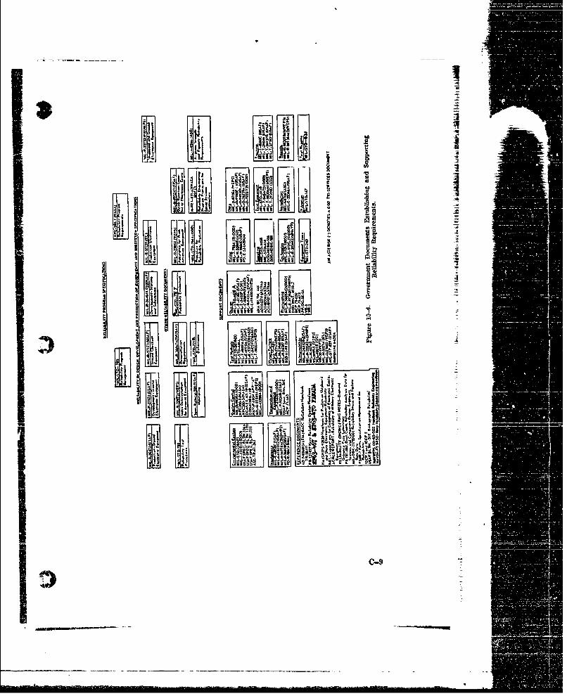
& 4 .___ I $!
It.. IIAllli s 4,l111 12• -
3~~ LifLeJa-- nfl - .
I !113ii ] i -J
,•.-. I S .L'II_ _ _' "_.r ...&
I3 I a ' *" a-z l a - S I JI 18 L
N'fl
"ls -
~-i1 A
0--9El
10.1.9 Initial Reliability Prediction
Eaci contractor shall be required to submit for PDA approval, an initialestimate of sub-system reliability inmmediately upon his completion of thepaper design of his equipment. The submission shall be in sufficient detaiias to permit 'he PDA to evaluate the validity of his prediction technique, itsapplication and its results. MIL--STD--56, should be reviewed by the PDA Ifor applicability in this phase of the program.101.A0 System Reliability Prediction
After evaluating each contractor's submission, the PDA will use these pre-dictions to esti-mate the roliability of the system in its various operating modes.Comparisons will be made between the predicted reliability in each mode andthe reliability goals woica were described in Section 10.1.1 herein.
10.1.11 Possible Reconfiguration of SystemAs a result of the comparison between predicted system reliability and the
reliability goals, it may be necessary to consider a reconfiguration of the system.If the goal exceeds the prediction, one may consider the use of redundancy ofunits or sub-systems or a redesign of equipment as means toward increasingthe overall predicted reliability. Another possible alternative is a review ofthe goals to reduce them to meet the prediction. This alternative should beconsidered in light of the potential increased cost in providing redundancyor improving the equipment design to enable the system to meet its initialreliability objective.
The prediction should always exceed the goal. If the prediction exceeds thegoal by a margin of over 2 to 1, a potential over-design situation exists.This conclusion is dependent upon the confidence level placed in the prediction.This confidence level must be based upon actual prior measurements on otherprojects which employed the same basic failure rate data and prediction tech-niques. Such a review of previous restlts should provide the Project Man-ager with an indication of the confidence ha msy place in the prediction. Forexample: a compilation of actual vs predictou MTBF's may indicate that theprediction is generally about 759 of the measured MTBF. If this factor,applied to the prediction, still results in a weighted prediction substantiallyexceeding the goal, the basic design should be reviewed to determine if anymodification can be made which, although it reduces the predicted MTBF,may also reduce the cost. Do not reduce the MTBF by design changes unlesscost or other benefits are evident. At this point a cost/effectiveness study shouldbe performed to provide the basic tradeoff data upon which such a decisionmay be made.
The review and updating of system configuration should be a process whichis employed after completing significant events in any phase of a project.It should occur during a reliability program whenever predictions or mess-urements result in overall system performance which is not in accord withsystem reliability goals.10.1.12 Reliability Design Reviews
As the design of the equipment progresses, each contractor should be re-quired to perform at least one critical reliability design review before freezing
C-10
Li
"- __ -
the design. Any changes in equipment configuration or major component com-
plement should be appraised and a new reliability prediction should be pro-duced The critical items of appraisal to be considered during such a revieware described in Paragraph 3.2.2.6 of MIL-R--22782B (SHIPS).
As a result of this review, it may be necessary to reconsider the system con-figuration as described in Section 10.1.10 herein. The PDA should carefullymonitor and evaluate the predictions and failure reports from all contractors.Since these predictions will, in general, not be available concurrently, the PDAshould carefully weigh the impact. of each contractor's prediction upon thereliability goals established by specification for each other contractor.10.1.13 Final Sub-System Reliability Prediction
When all design changes have been incorporated into the equipment and afinal configuration enists, the contractor should perform a final reliability pre-diction. This prediction should be appraised for its effect upon overall systemreliability, as are all predictions.
If required, the sgstem configuration should be reviewed for possible modi-ficatimn.10.1.14 Sub-System Reliability Demonstration
When a program of reliability demonstration is to be undertaken, bothundQ? development and/or production contracts, the resulting data should beevaluated in light of the reliability objectives.
At this point confidence levels in the measured MTBF can be quantitativelydetermined. (For details of this technique see NAVWEPS 00-65--502 Re-liability Handbook-Appendix 3.)
A final computation may now be performed, using actual data on sub-systemreliability, to predict system reliability. Again, a review of system configura-tion based upon a comparison of goals and extrapolated measurements shouldbe made.
As each succeeding prediction and appraisal is performed during the relia-bility program, the impact of each of these upon system configuration shoulddiminish. It is to be expected that major changes in configuration may occuras a result of the earlier predictions but the evaluation of the effect of the relia-bility d-nonstrationf on overall reliability should result iki little if sny alterationto the system.
A numtber of techniques of reliability demonstration are available for useduring this phase of the program. MIL-STD-781, "Test Levels and Accept/Reject Criteria for Reliability of Non-Expendable Electronic Equipment," out-lines a series of environmental test levels which can be employed for the purposeof reliability demonstration NAVWEPS 00-45-502, "Reliability Testing,"Sections 6 and 7, provide useful data for the de.3ign of tests for reliabilitydemonstration.10.1.15 System Reliability Demonstration
This phase measures the validity of all assumptions, predictions and analy-sis techniques previously employed.
In the case of a developmental equipment, teststnd evaluations, as describedin SECTION 12 of the TDP, are the vehicles through which system reliability is
C-il
I- 4
i
demonstrated. In the case of production equipments, the final in-service opera-tion provides the means for measuring system reliability. Regardless of howclosely conditions are simulated, and performance tests are planned, it is opera.tion under actual service conditions which provides the teclmique for fullevaluation. It is here that the maintenance procedures and operating pro.cedures are employed to stress the equipment with factors not existing in alaboratory or factory. I
Failure reports and equipment logs should be prepared in accordance withMIL-E-16400E, Amendment 4, Paragraph 3.1.8, General Specification, Elec- itronio Equipment, Naval Ship and Shore.
These reports provid ý a means for measuring system reliability with highconfidence and assist in the determination of the "true" MTBF.
10.1.16 Determination of OverpO. System ReliabilityAfter the "true" reliability a. . "true" maintainability of the system have
been determined as described in part in Section 10.1.15, the system availablitymay be determined from the following formula:
MTBFAvailability= XBF+tMTLR X100% (See Appendix C for Avail-
ability Nomograph)where MTBF (Mean-Time Between Failures) is the mean operating timeand MTTR (Mean-Time to Repair) is the mean down time, for each opera-tional mode of the system.
This is the final step in the reliability plan.10.2 Maintainability Assurance10.2. Maintainability Plan
The Events in a Maintainability Plan outlined in Figure 10-5 can be usedas a basis for most maintainability plans. As in the Reliability Plan, the PDAmust describe the procedures and techniques that will be employed during eachphase of the project and the degree of emphasis to be placed on each event. The * 4
major events of a typical maintainability plan are described in the followingparagraphs to guide the PDA in mak. y decisions which will ber'efected in the TDP.10.2•2 Establishment of Maintainability Goals
It is the responsibility of the Project Engineer to determine the systemquantitative maintainability goal within the framework of the operational andplanning information outlined in the SOR. A suitable reference guide for thistask is NAVSHIPS 94324, "Maintainability Design Criteria Handbook for De-signers of Shipboard Electronic Equipment," This document describes thevarious factors affecting maintainability and the mathematical techniques to beemployed in establishing system MTTR values.
10.2.3 Maintenance PhilosophyIn addition to providing essential data for the Supportability Plan, and the I
Personnel and Training Plan, the maintenance philosophy provides useful in-formation for predicting maximum and minimum requirements for MTTR
0-12
_.____________ _____
I_ __ _ - __ --Vi' i
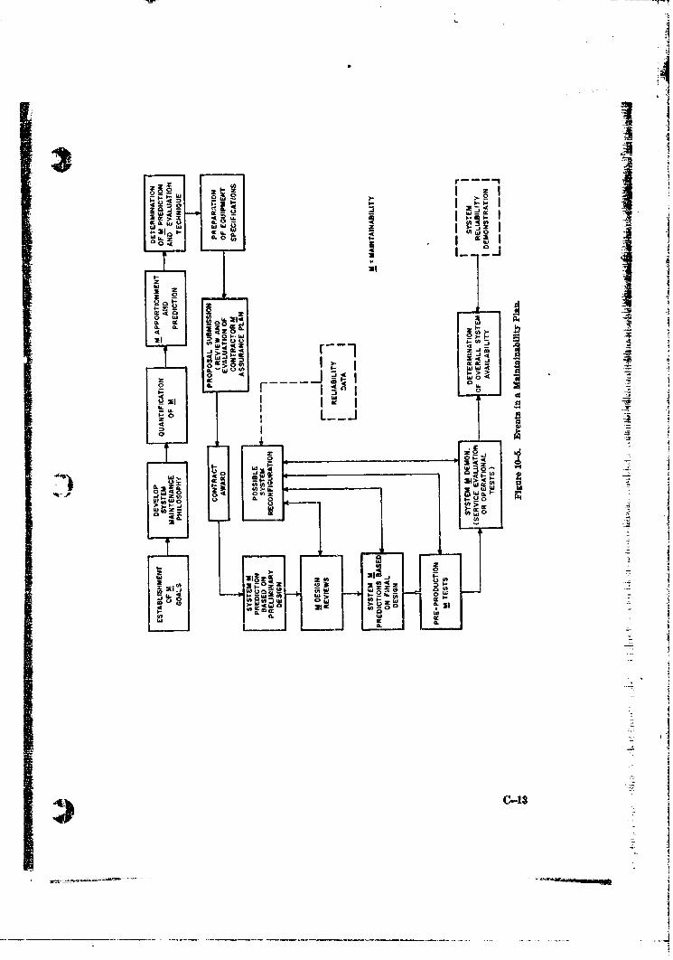
'A "AIL 044 a
00r - -
ZO..j I tL
"- 1- w
2-92
- 0It
0 >l
0 -to
w~z-
2 O
w~0J
W t c O D2&4- C
40 a Q W I I00 00 2iS
ILI
Ni
-. J

U
and for the allocation of the overall system maintainability measures to variousfunctional levels. The responsibility for developing the system maintenancephilosophy is amigned to the Project Engineer. Useful information on therelationship of elements in the maintenance cycle to maintainability design canbe found in NAVSHIPS 94.2.10.L4 Quallftcationof Maintainability
Development of numerical measures of maintainability for inclusion in theTDP can be accomplished by predictive methods based on information providedby the system maintenance r -losophy. Typical prediction methods and ex-pected ranges of MTTR for ious repair methods can be found in the main-tainability evaluation procedures of MIL-M-23313A (SHIPS) or MIL-S-
Since system availability (A) is a function of both MTBF and MTTR,MTBF ,
(A=MTBF+mIR
maximum and minimum values for MTrR should be stated whenever fixed- values are not specified. This will afford some degree of tradeoff betweenj-reliability and maintainability design for a specified value of A. Information
regarding MTBF-MTTR tradeoff possibilities is contained in NAVSHIPS94k24.
A10.2- Maintah -btlty ApportionmentK ' The allocation verall system measure of maintainability to lower order ele- .
meats of the system can be accomplished by prediction methods described inMMMW3(SISo MIL-S-2300. General information requirementsand the mathematical techniques for determining maintenance task times re-lated to each functional level of the system are provided in this document.10.2.6 Determination of Maintainability Predletion and Evaluation Tech-
At this point, factors which will influence the PDA decisions regarding re-
liability prediction and evaluation will also affect decisions concerning m@intain-ability prediction and evaluation. The alternate approaches to maintainabilityassurance which will be possible once the basic philosophy decision has beenmade, parallel those described (see Section 10.1.4) for implementing the relia-bility plan. Some of the maintainability documents which may be invokedare listed in Figure 10-4.10=7 Preopration of Equipment Specifications
All maintainability documents and procedures to be invoked must be in-eluded in the equipment specification. In defining performance parameters inthe epecification, the required measurs of MTTR should be included and thequality asurane provisions should include prediction, evaluation, monitoring,review and reporting methods and requirements. Maintainability specificationsmust give due consideration to human factors which affect system performance.Contractors should be cautioned to incorporate human resource constraints intheir design for maintainability. The specifications for maintainability re.quirements contained in MIL-M-23318A(SHIPS) are typical.
C-14 )
10.2.8 Proposal Submission and ReviewThe maintainability program submitted by the contractor should be re-
viewed jointly by the Project Manager and the Project Engineer to determineresponsiveness to specifications.10.29 Contract Award
Maintainability requirements should be included in the contractual docu-mentation in the manner described for reliability requirements (see Section10.1.7). _
10=210 System Maintainability Predictions and Design ReviewsInitial maintainability predictions submitted by the contractor(s) during
the design planning stage of the system research and development phase are usedby the PDA for early estimates of overall system maintainability. Methodsand schedules of evaluation to be used during the early design stages are usuallyleft to the contractor providing compliance with specifications in the final designis assured. Maintainability design reviews, whether independent or integratedwith reviews for other purposes, provide the means for implementing main-tainability design control necessary to assure (1) meeting the specific humanfactors criteria for the equipment or system in compliance with contract require-ments, and (2) changes affecting maintainability design are handled expe-ditiously. The final maintainability prediction(s) by contractor(s) should beanalyzed and the overall system maintainability prediction to determine if thespecified requirements will be met. System reconfiguration that might occurwill require a continuing effort of maintainability throughout the preprodue-tion and service evaluation test stages. Techniques and conformance/non-conformance criteria are provided in maintainability specifications listed inFigure 10-4. MIL-M-23313A(SHIPS) is typical of those imposed throughoutsystem development and production programs.10.2.11 Scheduled Maintenance Considerations
This section has appropriately emphasized the unscheduled aspects of main-tenance. Since all maintenance requirements must be considered in theMaintainability Plan, the Project Engineer is enjoined to include in his con-siderations, scheduled maintenance a.-pects uch as:
(1) Cycling or turn-around time requirements.(2) Provisions for concurrent servicing of the various subsystems.(3) System reqction time requirements.(4) Trouble-elhooting and fault diagnostic methods desired.
(5) The system maintenance conept and what it should include (levelsof maintenance and associated maintenance tasks and functions).
(6) Periodic (scheduled) maintenance requirements, including calendartime or operational limitations governing inspection and rework ofthe system.
(7) Maintenance manhour requirements or objectives per operating hour,per flight hour, or other measure of time or events.
(8) Maintenance and operating factors for personnel requirementsdeterminations(9) The required or desired degree of system readiness (availability).
C-15
_____
-3
(.
(10) Times required for fault identi~cation, isolation, correction and repairverification.
(11) Maintakiability verification schedules and methods used duringdevelopment effort.
(12) Types of missions, mission duration and frequency, or modes of op-eration, duration and frequency.
102.12 System Maintainability DemonstrationThe validity of all maintainability assumptions, predictions, and analysis
" _ •techniques for developmental equipment is measured during the planned tests---- --- and evaluations of SECTION 12. Data devised from the system maintainability
and reliability demonstrations are used to determine the overall system avail-F •ability as described in Section 10.1.15.
i ' I?I
K
i?,-l : I
I
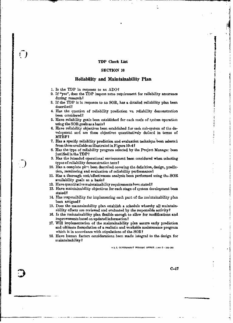
I
IITDP Check [ist
SECTION 10
Reliability and Maintainability Plan
1. Is the TDP in response to an ADO?2. If "yes", does the TDP impose some requirement for reliability assurance j
during research?3. If the TDP is in response to an SOR, has a detailed reliability plan been
described?4. Has the question of reliability prediction vs. reliability demonstration
been considered?5. Have reliability goals been established for each mode of system operation-
using the SOR goals as a basis I6. Have reliability objectives been established for each sub-system of the de-
velopment and are these objectives quantitatively dtfined in terms ofMTBFI
7. Has a specifle reliability prediction and evaluation technique been seleettifrom those available as illustrated in Figure 10-4?
8. Has the type of reliability program selected by the Project Manage, beenjustified in the TDP?
9. Has the intended operational environment been considered when selectingtypes of reliability demonstration tests?
10. Has a complete plcn been described covering the definition, design, predic-tion, monitoring and evaluation of reliability performancel
11. Has a thorough cost/effectiveness analysis been performed using thl3 SORavailability goals as a basis?
12. Have quantitative maintainability requirements been stated?13. Have maintainability objectives for each stage of system development been
stated I14. Has respons4ibility for im_1pleamentinlg eacha Part of thVAinaiailt plan1
been assigned ?15. Does the maintainability plan establish a schedule whereby all maintain-
ability efforts are reviewed and evaluated by the responsible activity?16. Is the maintainability plan flexible enough to allow for modifications and
improvements based on updated information?17. Will implementation of the maintainability plan assure early prediction
and ultimate formulation of a realistic and workable maintenance programwhich is in accordance with stipulations of the SOR?
18. Have human factors considerations been made integral to the design formaintainability?
SU., CCVERNMENT PRTING OFFICE I MI•0 - 200-350
C-17
cf- s•iJ, si .... of "ii body DOCUMENT CONTROL DATA - R & R E(Sorcu~rity Inm8 soil, at#On of Ititle, Ldy *I abs•trim aci PJidev.ri annotor i,, nauwr be enfered when the overall report I. (a cIaatied
RIG14A TING AC TI VITV (Corporate ourhori 0 EOTSCRIYCASFCTO
e6adquart~ars Naval Material Command UNCLASSIFIEDi(MAT 0325) Washington, D.C. 20360 2b. GROUP
3 REPORT TITLE
GUIDE FOR THE PREPARATION OF PROPOSED TECrHNICAL APPROACHES (PTA)
S [IESCnIoPTIVE NOTag (rype of report and Inchriorve date a)
5Aj TmONRIM (Firet name, middle Initial. M3et namee)
6. REPORT DATE 7a. TOTAL NO. OF PAG;S NO. OF R0EFS
February 196 7r 0( --"ai. CONTRACT O0 GRANT NO. a. (_0IINATOR$S REPORT NUoAISERASj
6. lloatcT NO NAVMAT P3910-A
9b. OTHER REP(ORT NO18 (Any other number. that may be aseelined" io) (SUPDOCS, GPO price $1.50)
Navy Stock No. 0518-093-1000, 0 DIS0IRISUTION STATEMENT
THIS DOCUMENT HAS BEEN APPROVEDFOR PUBLIC RELEASE AND SALE;
"ITS DISTRIBUTION IS UNLIMITED
It. SUIDSL[IK0,16N A V NOTES ,Ia. SPONSORING MII.iTARY ACTIVITY
C mpaxion document to NA.VIAT P3910 "Guide Headquarters Naval Material Commandfor the Preparation of Technical Develop- (MAT 0325) Washington, D.C. 20360Melt Plans"
w3 A44TIAC T
This document provides guidelines for the preparation of /I•oposed,,TechnicalApproaches (PTAs) and an explanation of the need for the required information. Itis intended as a guide rather than an inflexible set of rules.
The PTA Itself is the initial Research and Zevelopment document which forecastsprocurement worAlaoad in R&D, and presents alternative approaches for a system or
component concept stated or implied in aGeneral Operational Requirement.
D D I (PAGE 1)-UNCLASSIFIEDs'ictnDD,°.,o, 6,.14 73 i)•T•SF•
•/ 0 0 6. 111 • ':0 1 Secu rity C la .nsific ation