Embed Size (px)
Citation preview
VARIATOR
Voltagephase 1to phase 2
Voltagephase 2to neutral
Voltagephase 1to neutral
GUIDE
TECHNICAL GUIDE TECHNICAL GUIDE
FREQUENCY INVERTER CONTROL FOR HOISTING AND TRAVELLING
VERLINDE reserve the right to alter or amend the above information without notice 12/04 VESAGBVA01A
VARIATOR
TECHNICAL GUIDE Page 1
This manual provides the basic information of Variator T Vector and Variator L Vector, their function, features and applications. The information in this manual is more or less qualitative and thus this manual must not be
used as a design instruction.
i) CONTENTS
i) CONTENTS ......................................................................................... 1
ii) WHAT IS VARIATOR FAMILY ............................................................... 2
iii) ADVANTAGES OF VARIATOR ............................................................. 4
1 WHAT IS VARIATOR ............................................................................ 6 1.1 BASIC DESCRIPTION ....................................................................... 6 1.2 MAIN COMPONENTS ..................................................................... 7 1.3 ACCESSORIES ............................................................................ 11
2 DISPLAY PANEL ................................................................................ 12
3 CONTROL FEATURES ......................................................................... 13 3.1 CONTROL METHODS.................................................................... 13 3.2 ADVANCED FEATURES .................................................................. 15
4 MOTOR CONTROL............................................................................ 16 4.1 VECTOR CONTROL ...................................................................... 16
4.1.1 OPEN LOOP VECTOR CONTROL............................................ 17 4.1.2 CLOSED LOOP VECTOR CONTROL ......................................... 17
4.2 MOTOR CONTROL MODES ............................................................ 18
5 APPLICATIONS ................................................................................. 19 5.1 VARIATOR IN A STANDARD VT-HOIST............................................... 19 5.2 VARIATOR IN A PAPER MILL CRANE .................................................. 20 5.3 VARIATOR IN AN AUTOMATED WAREHOUSE CRANE .............................. 21
6 TERMINOLOGY OF VARIATOR ........................................................... 22
VERLINDE reserve the right to alter or amend the above information without notice Dec 04 VESAGBVA01A
VARIATOR
TECHNICAL GUIDE Page 2
ii) WHAT IS VARIATOR FAMILY Variator Family is the name of the frequency control product developed and manufactured by VERLINDE . Variator Family is a complete control system for every crane motion providing Dynamic and safe crane operation. Variator Family includes Dynam for light and Variator Vector for heavier travelling applications, and Variator Vector for hoisting. Their robust construction ensures excellent tolerance to poor ambient conditions. This Product File provides the basic information of Variator Vector, which are based on the VERLINDE-inverter.
• More than a product
VARIATORFAMILY
Deliverytime
VERLINDEsupport
Provensolution
Documentation
Spareparts
Made forcranes
Testing
Training
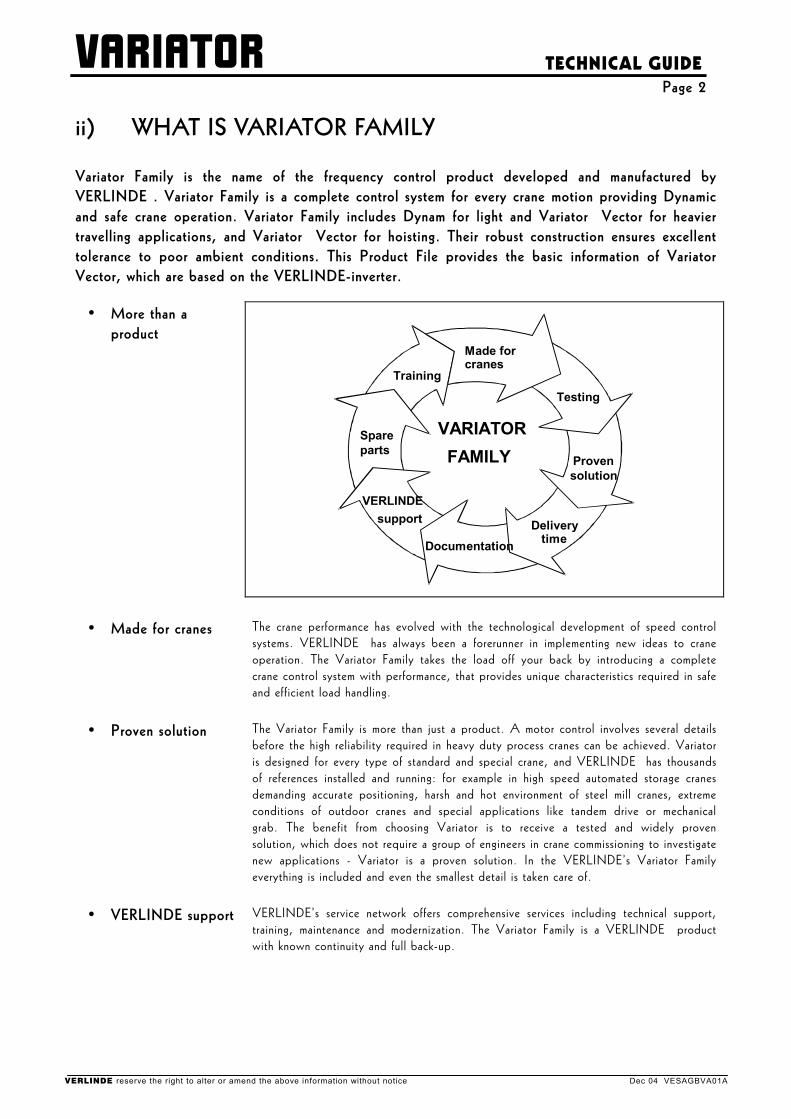
• Made for cranes The crane performance has evolved with the technological development of speed control systems. VERLINDE has always been a forerunner in implementing new ideas to crane operation. The Variator Family takes the load off your back by introducing a complete crane control system with performance, that provides unique characteristics required in safe and efficient load handling.
• Proven solution The Variator Family is more than just a product. A motor control involves several details before the high reliability required in heavy duty process cranes can be achieved. Variator is designed for every type of standard and special crane, and VERLINDE has thousands of references installed and running: for example in high speed automated storage cranes demanding accurate positioning, harsh and hot environment of steel mill cranes, extreme conditions of outdoor cranes and special applications like tandem drive or mechanical grab. The benefit from choosing Variator is to receive a tested and widely proven solution, which does not require a group of engineers in crane commissioning to investigate new applications - Variator is a proven solution. In the VERLINDE’s Variator Family everything is included and even the smallest detail is taken care of.
• VERLINDE support VERLINDE’s service network offers comprehensive services including technical support, training, maintenance and modernization. The Variator Family is a VERLINDE product with known continuity and full back-up.
VERLINDE reserve the right to alter or amend the above information without notice Dec 04 VESAGBVA01A
VARIATOR
TECHNICAL GUIDE Page 3
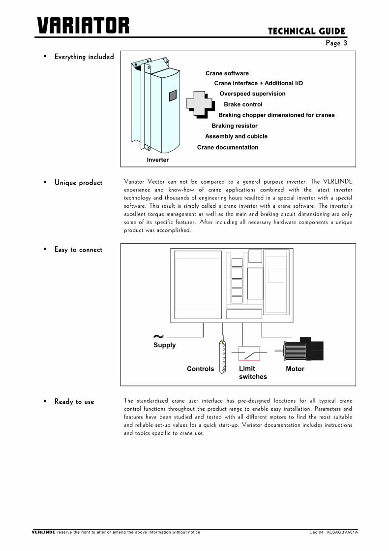
• Everything included
Crane software
Overspeed supervision
Crane interface + Additional I/O
Braking resistor
Braking chopper dimensioned for cranes
Assembly and cubicle
Brake control
Crane documentation
Inverter
• Unique product Variator Vector can not be compared to a general purpose inverter. The VERLINDE experience and know-how of crane applications combined with the latest inverter technology and thousands of engineering hours resulted in a special inverter with a special software. This result is simply called a crane inverter with a crane software. The inverter’s excellent torque management as well as the main and braking circuit dimensioning are only some of its specific features. After including all necessary hardware components a unique product was accomplished.
• Easy to connect
Supply
MotorLimitswitches
Controls
• Ready to use The standardized crane user interface has pre-designed locations for all typical crane control functions throughout the product range to enable easy installation. Parameters and features have been studied and tested with all different motors to find the most suitable and reliable set-up values for a quick start-up. Variator documentation includes instructions and topics specific to crane use.
VERLINDE reserve the right to alter or amend the above information without notice Dec 04 VESAGBVA01A
VARIATOR
TECHNICAL GUIDE Page 4
iii) ADVANTAGES OF VARIATOR STEPLESS CONTROL has many advantages and offers many new features, when compared to 1- and 2-speed controls and multistep control systems.
• Easy to use Stepless control ensures an easy, safe and precise load handling. Variator takes the load off your back by offering a very low minimum speed for improved positioning accuracy. For less experienced crane operators this results in less load damages as they can adjust the speed to their skills.
• Increased productivity
Stepless control offers smooth starts, fast acceleration and soft stops for optimized load handling with no load damages. A reduced cycle time and better productivity can be achieved, when both a very low creeping speed and a very high main speed are used.
• Lower maintenance costs
Stepless control enables the use of electrical braking for deceleration before applying the mechanical brake. In Variator Family stepless control the electrical braking is provided in all circumstances. Electrical braking reduces brake wear, because the mechanical brake is used only as a holding brake.
• Longer lifetime Stepless control reduces the mechanical stresses due to smooth starts and soft stops. The reduced amount and level of shocks and impacts to the components and steel structure enable a longer functioning condition of the crane.
FREQUENCY CONTROL has many advantages and offers many new features, when compared to other stepless control systems.
• Squirrel cage motor Frequency control - as an inverter based control - utilizes a squirrel cage motor, which is inexpensive, small in size and has low weight when compared to other motor types. A squirrel cage motor has also good tolerance to poor ambient conditions and a simple, robust construction requiring only minimal regular maintenance.
• No external components
Frequency control requires practically no external components for controlling a squirrel cage motor. The normal speed control characteristics can be achieved without any rotor contactors or tachometers.
• Selectable output values
Frequency control offers selectable maximum motor voltage and frequency, which are not dependent on the supply voltage and frequency. This feature makes it even possible to use motors, which have ratings different from the power supply line.
• Speed control range Frequency control has a wide speed control range and allows the use of low speeds with minimal driving time limitations due to minimal motor heating. Frequency control also allows to drive the motor at frequencies higher than the nominal supply frequency, when using field weakening.
• Economical power supply
Frequency control offers good efficiency and displacement factor and also allows the use of lighter power supply components due to a low starting current, which is proportional to the needed acceleration torque.
VERLINDE reserve the right to alter or amend the above information without notice Dec 04 VESAGBVA01A
VARIATOR
TECHNICAL GUIDE Page 5 VARIATOR have many advantages and offer many new features, when compared to other inverter based systems, which might be used in crane applications.
• VERLINDE-inverter Variator are based on the VERLINDE-inverter, a special crane inverter. The hardware and the software of this inverter is especially designed for VERLINDE to include the specific features required in crane applications.
• Crane user interface Variator have exactly the same interface with pre-designed locations for all typical crane functions. The main part of this interface is carried out by a terminal strip, which has separated sections for signals with main, control and electronics voltage levels.
• Line contactor
Variator include a line contactor. The line contactor is dimensioned to function as the main isolator by isolating the frequency control from the power supply if the inverter notices a fault.
• Brake control
Variator include the brake contactor and the required components for controlling the mechanical brake. The full/half-wave rectifier for disk brakes and/or the thrustor brake connection are provided depending on the power rating of the frequency control.
• Electrical braking
Variator include the braking transistor, which is dimensioned for every crane application. The braking resistor for electrical braking is also included in Variator.
• Selectable control voltage
Variator include an internal control voltage transformer. The internal transformer offers a 48VAC output, which is always used for the External Stop circuit and can be used for all command and control signals. The I/O card also allows use of 48/115/230VAC level control signal for all other circuits.
• Control methods
Variator can be controlled by the electronic potentiometer control with 2-step pushbuttons, the potentiometer control with analog joystick-type control, the automation control with PLC and radio controls and the multistep control with 2-4-step controllers. All these control methods are available with every Variator.
• Limit switch functions
Variator have built-in slowdown and stop limit switch functions for both running directions. The slowdown limit switch function can be selected to limit the speed proportionally to time or to the travel distance to the stop limit switch.
• Speed supervision
Variator includes a speed supervision unit, which is separate from the inverter and not dependent on software. This safety circuitry is used in hoisting applications to monitor the speed of the motor. In case of speed difference, overspeed or stall the speed supervision unit stops the motion immediately.
• Protections Variator include a motor thermal protection, which is based on motor temperature measurement by thermistors placed in motor windings. The great number of other protections included in every Variator are shown in the technical data.
• Common components
Variator belong to the Variator Family, so a great number of common components minimize the spare part inventory and simplify the maintenance procedures.
VERLINDE reserve the right to alter or amend the above information without notice Dec 04 VESAGBVA01A
VARIATOR
TECHNICAL GUIDE Page 6
1 WHAT IS VARIATOR T / VARIATOR L
1.1 Basic description
•
•
•
Frequency control Variator T for travelling Variator L for hoisting
Variator is a complete control system, especially designed for crane operation by VERLINDE . Variator T is a frequency control for all kinds of travelling applications, where Variator L is a frequency control for hoisting, including the speed supervision features required for safe hoisting operation. A frequency control is an inverter based motor control system, which controls the speed by changing the voltage frequency of a sturdy squirrel cage motor. By these means a stepless speed control can be achieved. In addition to the inverter, the frequency control includes all required main components and features to make it a complete crane motor control.
•
•
•
VERLINDE-inverter VERLINDE-hardware VERLINDE-software
The inverter in Variator is a crane inverter, designed and manufactured especially for VERLINDE . The specific crane features for the inverter hardware and the special software are achieved by combining the VERLINDE experience and know-how of crane applications with the latest technology. The VERLINDE-inverter uses vector calculation for a total of six different motor control modes, with or without encoder feedback.
• Optimal models Every Variator can be operated in open loop or closed loop control. The optimal model for the application can be selected between the P-expansion when the speed feedback is not required and the N-expansion either for speed feedback or more input and output functions.
• Tested parameters Variator includes tested parameters with different motors for all power ratings. This is a benefit, that makes every Variator delivery a proven solution. The tested and pre-set motor parameters enable a quick start-up in crane commissioning, also in modernizations.
• Electrical braking The braking method used in Variator is electrical braking. The braking circuit includes a braking transistor and a braking resistor for dissipating the braking energy. The braking circuit is included in every Variator.
• Assembly and cubicles
Variator assembly follows a standard layout. The cubicles, especially developed for crane use guarantee the correct ventilation and a strong, compact mechanical construction.
VERLINDE reserve the right to alter or amend the above information without notice Dec 04 VESAGBVA01A
VARIATOR
TECHNICAL GUIDE Page 7
1.2 Main components
• Inverter Variator is based on the VERLINDE-inverter, which includes the crane features both in hardware and in software. The main circuit of the inverter is dimensioned for a supply voltage range from 380V to 500V for 50/60Hz and the braking circuit always includes components dimensioned for hoisting applications. The through-mounted construction allows natural ventilation for the heatsink and other heating parts, when assembled in cubicles developed for Variator. This type of construction and assembly keeps the internal temperature of the cubicle lower and more suitable for the control electronics. The application software in the inverter handles the typical crane functions according to the inputs, outputs and the set parameters in real-time multitasking. The basis of the inverter is a highly developed ASIC (Application Specific Integrated Circuit) and the adaptive motor model. On top of this are the vector control algorithms for both open loop control without encoder feedback and for closed loop control with encoder feedback. The inverter software has six motor control modes:
• frequency control, open loop and closed loop • speed control, open loop and closed loop • torque control, open loop and closed loop
• Line contactor The line contactor included in Variator is dimensioned to function as the main isolator of the frequency control. The line contactor isolates Variator from the power supply, if the inverter notices a fault or if the temperature of internal braking resistors is too high. The External Stop circuit de-energizes the line contactor immediately, regardless of the driving situation. One advantage of the line contactor is, that in crane commissioning every frequency control can be powered up separately.
VERLINDE reserve the right to alter or amend the above information without notice Dec 04 VESAGBVA01A
VARIATOR
TECHNICAL GUIDE Page 8
• Brake contactor The brake contactor and other required components are included for controlling the mechanical brake. The brake circuit is protected by an internal circuit breaker. Depending on the power rating of the frequency control, the full/half-wave rectifier for disk brakes or the thrustor brake connection or both of them are provided. The braking and the brake contactor are controlled by the inverter, and the brake is controlled closed when the stop limit switch operates or in case of any fault. The External Stop circuit de-energizes the brake contactor immediately and in Variator the speed supervision fault will also cause the brake to close.
• Braking resistor Variator includes the braking transistor and the braking resistor for resistor braking. The braking transistor is always dimensioned for hoisting application and is though powerful enough for all travelling applications as well. This simplifies the application as there is no need of external braking choppers.
• Control voltage transformer
The internal control voltage transformer in Variator has connection points in the primary for all common power supply line voltages from 380V to 500V. For safety reasons, the transformer is protected by the same circuit breaker as the brake circuit. The transformer provides a 48VAC output, which is always used for the External Stop circuit. The same 48VAC can also be used for all command and control signals as an internal control voltage. The transformer also has a 230VAC output for the cooling fans in Variator L with internal braking resistors. Both secondary circuits are protected by fuses.
• I/O-card
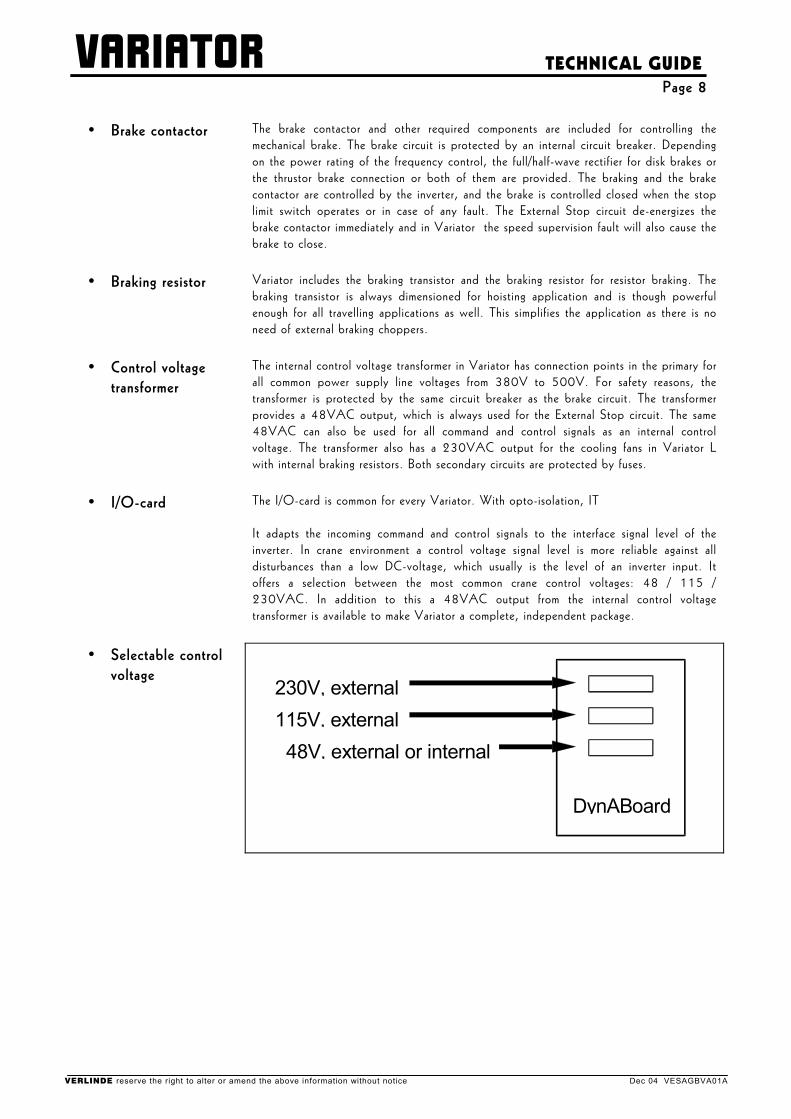
The I/O-card is common for every Variator. With opto-isolation, IT It adapts the incoming command and control signals to the interface signal level of the inverter. In crane environment a control voltage signal level is more reliable against all disturbances than a low DC-voltage, which usually is the level of an inverter input. It offers a selection between the most common crane control voltages: 48 / 115 / 230VAC. In addition to this a 48VAC output from the internal control voltage transformer is available to make Variator a complete, independent package.
• Selectable control voltage
230V, external115V, external
48V, external or internal
DynABoard
VERLINDE reserve the right to alter or amend the above information without notice Dec 04 VESAGBVA01A
VARIATOR
TECHNICAL GUIDE Page 9
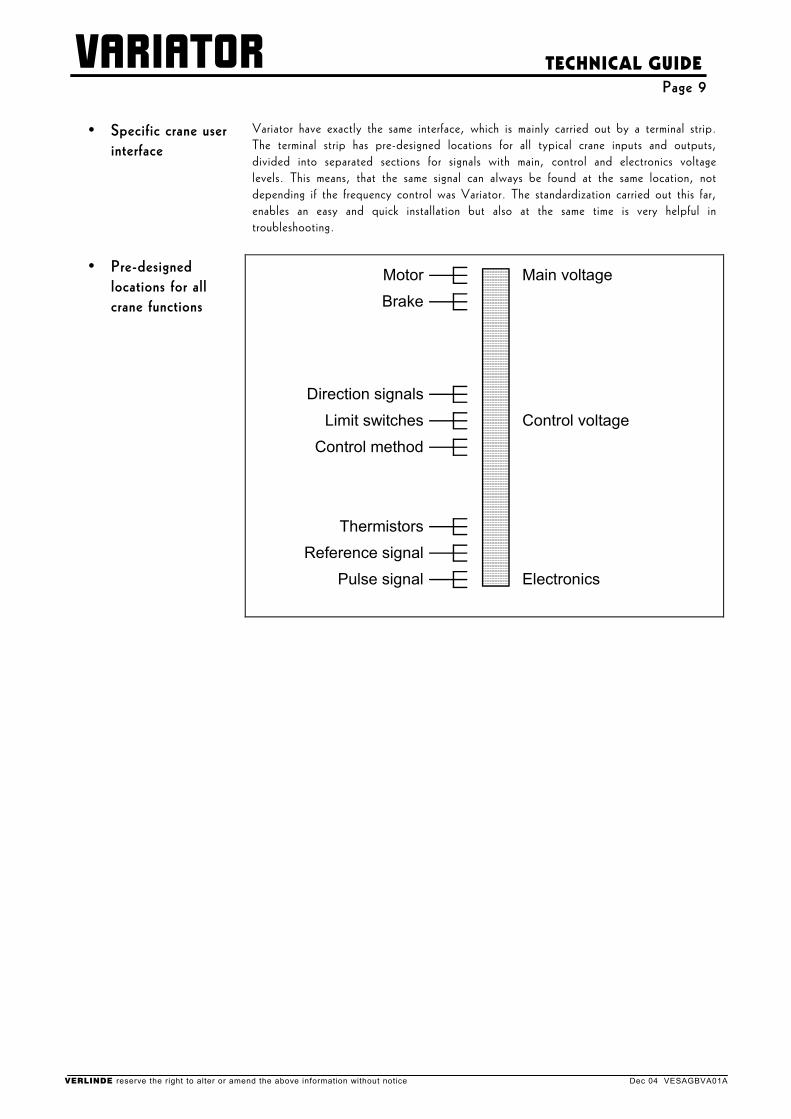
• Specific crane user interface
Variator have exactly the same interface, which is mainly carried out by a terminal strip. The terminal strip has pre-designed locations for all typical crane inputs and outputs, divided into separated sections for signals with main, control and electronics voltage levels. This means, that the same signal can always be found at the same location, not depending if the frequency control was Variator. The standardization carried out this far, enables an easy and quick installation but also at the same time is very helpful in troubleshooting.
• Pre-designed locations for all crane functions
Main voltage
Control voltage
Electronics
Thermistors
Control method
Limit switches
Direction signals
Motor
Reference signal
Pulse signal
Brake
VERLINDE reserve the right to alter or amend the above information without notice Dec 04 VESAGBVA01A
VARIATOR
TECHNICAL GUIDE Page 10
• Speed supervision unit for Variator L
Hoist speed supervision in Variator L is carried out by detecting the actual speed of the motor by counting pulses from a pulse wheel or from an encoder located on the motor shaft. This pulse frequency is compared to the inverter output frequency. As a result of this, three different speed supervision functions are available:
• overspeed supervision • stall supervision • speed difference supervision
•
•
•
Overspeed Stall Speed difference
If the pulse frequency exceeds the pre-set value (usually 115-125% of the nominal speed), an overspeed is detected. It has a separate setting for the Extended Speed Range (ESR). Correspondingly, if the time gap between two pulses is too long, a stall situation is detected. The speed difference supervision stops the motion if the actual speed of the motor differs too much from the inverter output frequency.
•
Separate from the inverter
The speed supervision unit is made to be separate from the inverter and independent of the inverter software. This is to ensure that no single component failure is able to cause a dangerous situation.
VERLINDE reserve the right to alter or amend the above information without notice Dec 04 VESAGBVA01A
VARIATOR
TECHNICAL GUIDE Page 11
1.3 Accessories
• Cubicles for crane use
VERLINDE has developed special cubicles for crane use. These cubicles are designed for minimum height and correct ventilation. Each Variator has a cubicle for installation without any additional parts. Variator with a smaller power rating can also be installed in bigger cubicles to maintain the equal height cubicle row assembly.
VERLINDE reserve the right to alter or amend the above information without notice Dec 04 VESAGBVA01A
VARIATOR
TECHNICAL GUIDE Page 12
2 DISPLAY PANEL
• Interchangeable displays
Variator has a digital display panel for programming and monitoring. The display panel can be either of LED or Graphical display type and includes a keyboard and a display.90 The display panels are removable and fully interchangeable, and can be used in all Variator frequency controls.
VERLINDE reserve the right to alter or amend the above information without notice Dec 04 VESAGBVA01A
VARIATOR
TECHNICAL GUIDE Page 13
3 CONTROL FEATURES
3.1 Control methods
• Four control methods (command modes)
Variator has four different control methods (command modes) as standard. The selection between control methods is done by electrical input signals (selections switches). Variator itself does not need any changes when selecting different modes. This means that any single Variator may be used in any or all of these command modes. Variator is thus extremely easy to apply in cranes where several control places are necessary, for example EP-mode with push-button station and PO-mode for cabin control.
• EP-control -electronic motor potentiometer
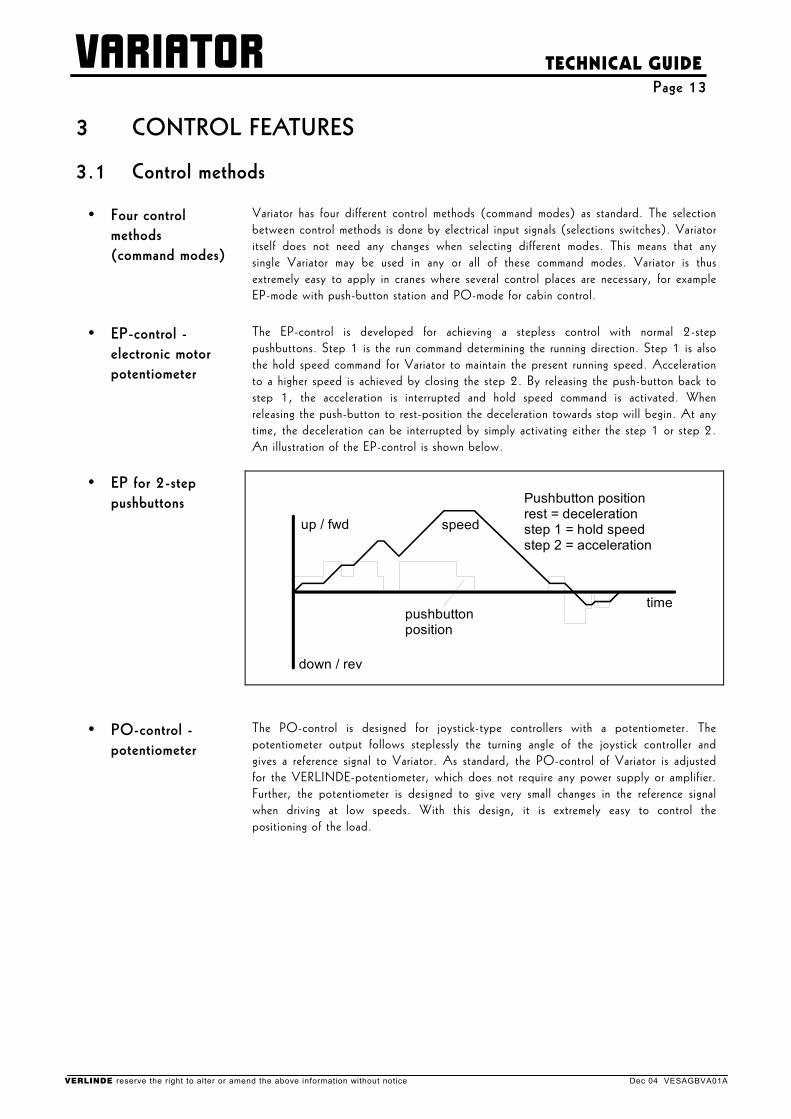
The EP-control is developed for achieving a stepless control with normal 2-step pushbuttons. Step 1 is the run command determining the running direction. Step 1 is also the hold speed command for Variator to maintain the present running speed. Acceleration to a higher speed is achieved by closing the step 2. By releasing the push-button back to step 1, the acceleration is interrupted and hold speed command is activated. When releasing the push-button to rest-position the deceleration towards stop will begin. At any time, the deceleration can be interrupted by simply activating either the step 1 or step 2. An illustration of the EP-control is shown below.
• EP for 2-step
pushbuttons
Pushbutton positionrest = decelerationstep 1 = hold speedstep 2 = acceleration
speed
pushbuttonposition
up / fwd
down / rev
time
• PO-control -potentiometer
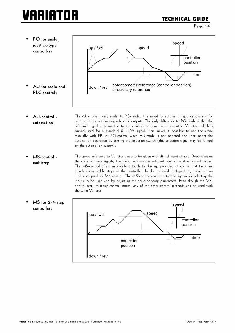
The PO-control is designed for joystick-type controllers with a potentiometer. The potentiometer output follows steplessly the turning angle of the joystick controller and gives a reference signal to Variator. As standard, the PO-control of Variator is adjusted for the VERLINDE-potentiometer, which does not require any power supply or amplifier. Further, the potentiometer is designed to give very small changes in the reference signal when driving at low speeds. With this design, it is extremely easy to control the positioning of the load.
VERLINDE reserve the right to alter or amend the above information without notice Dec 04 VESAGBVA01A
VARIATOR
TECHNICAL GUIDE Page 14
•
•
PO for analog joystick-type controllers AU for radio and PLC controls
up / fwd
down / rev
speedspeed
controllerposition
time
potentiometer reference (controller position)or auxiliary reference
• AU-control -automation
The AU-mode is very similar to PO-mode. It is aimed for automation applications and for radio controls with analog reference outputs. The only difference to PO-mode is that the reference signal is connected to the auxiliary reference input circuit in Variator, which is pre-adjusted for a standard 0...10V signal. This makes it possible to use the crane manually with EP- or PO-control when AU-mode is not selected and then select the automation operation by turning the selection switch (this selection signal may be formed by the automation system).
• MS-control -multistep
The speed reference to Variator can also be given with digital input signals. Depending on the state of these signals, the speed reference is selected from adjustable pre-set values. The MS-control offers an excellent touch to driving, provided of course that there are clearly recognizable steps in the controller. In the standard configuration, there are no inputs assigned for MS-control. The MS-control can be activated by simply selecting the inputs to be used and by adjusting the corresponding parameters. Even though the MS-control requires many control inputs, any of the other control methods can be used with the same Variator.
• MS for 2-4-step controllers
speed
controllerposition
up / fwd
down / rev
time
speed
controller position
VERLINDE reserve the right to alter or amend the above information without notice Dec 04 VESAGBVA01A
VARIATOR
TECHNICAL GUIDE Page 15
3.2 Advanced features
• Limit switch functions
Variator includes a 2-step limit switch function. There are input terminals for slowdown and stop limit switch signals for both directions. With the basic slowdown function, the speed is limited down to an adjustable value. The advanced limit switch function limits the speed with respect to the travel position, and enables an effective crane operation in the slowdown area.
• Intelligent ramps In addition to the standard separately adjustable acceleration and deceleration ramps, Variator provides the possibility to apply intelligent speed dependent ramps. A slow ramp at the lowest speeds enables easy load positioning and a fast ramp with the highest speeds provides a short stopping distance. A second set of ramps is a specialty in AU-command mode, enabling fast cycles with automation and yet smooth operation when driven manually.
• Extended Speed Range
Extended Speed Range (ESR) enables driving with speeds exceeding the nominal speed of the motor, with light loads and when the crane is mechanically designed accordingly. This is possible by increasing the supply frequency of the motor above nominal with the field weakening principle. At the same time the available pull-out torque reduces and full load can not be applied. With light loads (typically less than 20% of the nominal load) it is possible to drive even twice the nominal speed. The speed supervision unit includes two separately adjustable operating levels ensuring maximum safety - with heavy loads at normal operating speeds as well as with the highest ESR speeds at light load conditions. In most travelling applications, regardless of the load, a relatively high braking torque is needed and the possibility to apply the ESR with Variator must be considered case by case.
• Synchronization Variator includes a correction signal input (signal KR, available with N-expansion), which can be used in applications where exact synchronization of two or more machineries is necessary. In such cases, a separate synchronization device is needed to measure the distance error and to form the correction signal for Variator. Although a separate KR-signal is not available with the P-expansion, the synchronization function can be activated by parameters and connecting the correction signal to the AS-input. Note, that this synchronization feature is not needed very often, because equal motors run very accurately by nature when they are controlled by a common reference signal and have equal loads. Alternatively the synchronization can be made in the automation and by connecting a different reference signal for each Variator.
VERLINDE reserve the right to alter or amend the above information without notice Dec 04 VESAGBVA01A
VARIATOR
TECHNICAL GUIDE Page 16
4 MOTOR CONTROL
• Frequency control range
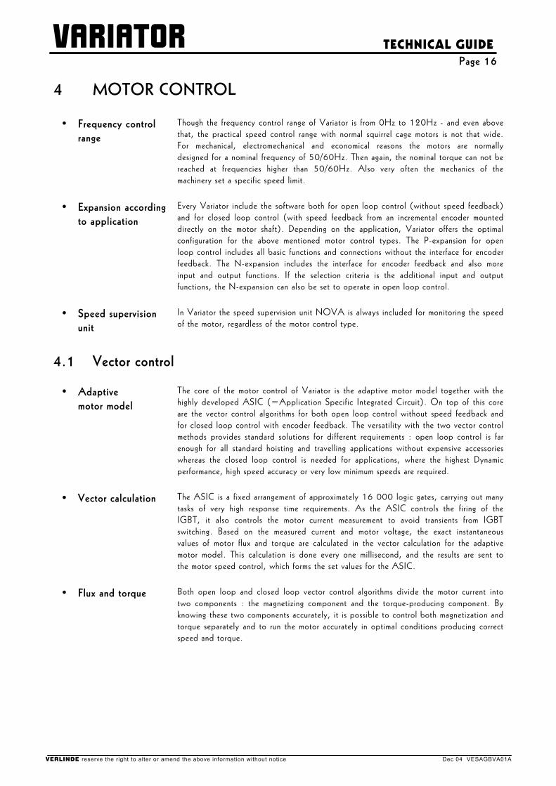
Though the frequency control range of Variator is from 0Hz to 120Hz - and even above that, the practical speed control range with normal squirrel cage motors is not that wide. For mechanical, electromechanical and economical reasons the motors are normally designed for a nominal frequency of 50/60Hz. Then again, the nominal torque can not be reached at frequencies higher than 50/60Hz. Also very often the mechanics of the machinery set a specific speed limit.
• Expansion according to application
Every Variator include the software both for open loop control (without speed feedback) and for closed loop control (with speed feedback from an incremental encoder mounted directly on the motor shaft). Depending on the application, Variator offers the optimal configuration for the above mentioned motor control types. The P-expansion for open loop control includes all basic functions and connections without the interface for encoder feedback. The N-expansion includes the interface for encoder feedback and also more input and output functions. If the selection criteria is the additional input and output functions, the N-expansion can also be set to operate in open loop control.
• Speed supervision unit
In Variator the speed supervision unit NOVA is always included for monitoring the speed of the motor, regardless of the motor control type.
4.1 Vector control
• Adaptive motor model
The core of the motor control of Variator is the adaptive motor model together with the highly developed ASIC (=Application Specific Integrated Circuit). On top of this core are the vector control algorithms for both open loop control without speed feedback and for closed loop control with encoder feedback. The versatility with the two vector control methods provides standard solutions for different requirements : open loop control is far enough for all standard hoisting and travelling applications without expensive accessories whereas the closed loop control is needed for applications, where the highest Dynamic performance, high speed accuracy or very low minimum speeds are required.
• Vector calculation The ASIC is a fixed arrangement of approximately 16 000 logic gates, carrying out many tasks of very high response time requirements. As the ASIC controls the firing of the IGBT, it also controls the motor current measurement to avoid transients from IGBT switching. Based on the measured current and motor voltage, the exact instantaneous values of motor flux and torque are calculated in the vector calculation for the adaptive motor model. This calculation is done every one millisecond, and the results are sent to the motor speed control, which forms the set values for the ASIC.
• Flux and torque Both open loop and closed loop vector control algorithms divide the motor current into two components : the magnetizing component and the torque-producing component. By knowing these two components accurately, it is possible to control both magnetization and torque separately and to run the motor accurately in optimal conditions producing correct speed and torque.
VERLINDE reserve the right to alter or amend the above information without notice Dec 04 VESAGBVA01A
VARIATOR
TECHNICAL GUIDE Page 17
4.1.1 Open loop vector control
• Without speed feedback
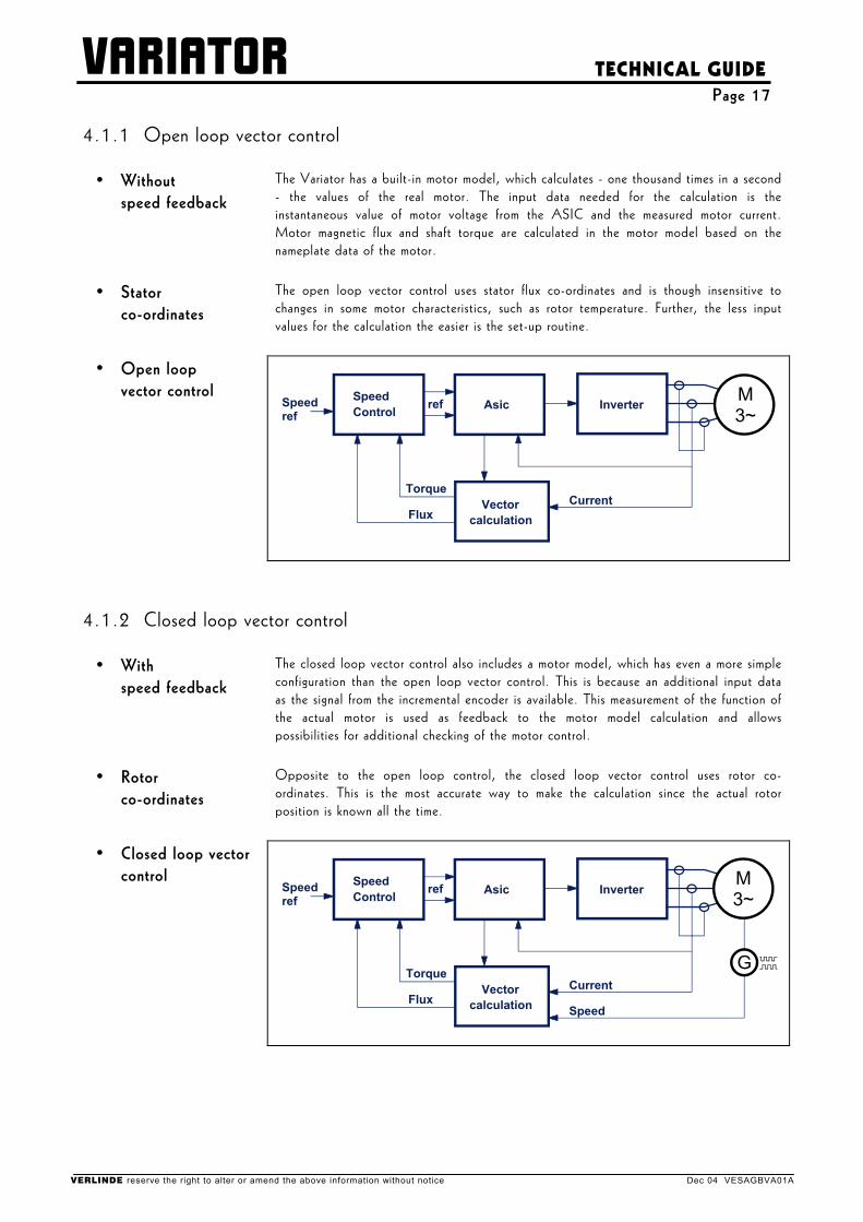
The Variator has a built-in motor model, which calculates - one thousand times in a second - the values of the real motor. The input data needed for the calculation is the instantaneous value of motor voltage from the ASIC and the measured motor current. Motor magnetic flux and shaft torque are calculated in the motor model based on the nameplate data of the motor.
• Stator co-ordinates
The open loop vector control uses stator flux co-ordinates and is though insensitive to changes in some motor characteristics, such as rotor temperature. Further, the less input values for the calculation the easier is the set-up routine.
• Open loop vector control
Speedref
InverterAsic
Current Vectorcalculation
SpeedControl
Torque
Flux
ref M3~
4.1.2 Closed loop vector control
• With speed feedback
The closed loop vector control also includes a motor model, which has even a more simple configuration than the open loop vector control. This is because an additional input data as the signal from the incremental encoder is available. This measurement of the function of the actual motor is used as feedback to the motor model calculation and allows possibilities for additional checking of the motor control.
• Rotor co-ordinates
Opposite to the open loop control, the closed loop vector control uses rotor co-ordinates. This is the most accurate way to make the calculation since the actual rotor position is known all the time.
• Closed loop vector control
Speedref
InverterAsic
Current Vectorcalculation
SpeedControl
Torque
Flux
ref
Speed
M3~
G
VERLINDE reserve the right to alter or amend the above information without notice Dec 04 VESAGBVA01A
VARIATOR
TECHNICAL GUIDE Page 18
4.2 Motor control modes
• Flexibility with vector control
The motor control in Variator is a vector control system regardless of the way the reference signal is handled. With the Variator a great flexibility for any crane application is achieved by the possibility to drive with a frequency reference, with a speed reference with slip compensation and even with a torque reference. With these three modes, most of the crane applications can be handled without any speed feedback using the open loop vector control. For the ultimate performance, all the three modes are available with the closed loop vector control as well. Guidelines to determine the best control for any crane application are given below.
• Frequency reference In frequency control mode the motor frequency follows the frequency reference signal. The actual rotating speed depends on load and is equal to the slip below or above the output frequency. Even with frequency control, the vector calculation is used to keep the magnetization at a correct level.
This method is most suitable for bridge travelling control in cases where both ends of the bridge are driven with separate Variator T and as well for any application, where two or more Variator T control the same motion with several separate machineries, which are mechanically coupled together.
• Speed reference In speed control mode the motor speed follows the speed reference signal. Variator adjusts the motor frequency and with this function compensates the load-dependent slip.
This method is most suitable for hoisting and as well for most bridge and trolley travelling applications. The slip compensation keeps the actual shaft speed constant and independent of loading conditions. With open loop speed control, the applicable minimum speed is about equal to motor rated slip for hoisting and about one third of motor rated slip for travelling. With the closed loop speed control it is even possible to reach zero speed with full torque. In bridge travelling it has to be noted, that the ends of the bridge do not necessarily run at equal speeds, because of unequal bridge loading or the quality of the runway. Therefore it may be necessary to increase the minimum speed up to the rated slip.
For bridge travelling control in cases where the ends of the bridge are driven with separate Variator T, an additional anti-skew controller might be needed - specially in fast cranes and with long spans - to compensate the mechanical and electrical tolerances which would otherwise lead to bridge skewing.
• Torque reference In torque control mode the shaft torque is kept equal to the reference signal. The motor speed depends very much on loading conditions - for example an unloaded motor would run at full speed all the time. For safety reasons, the speed is limited between adjustable minimum and maximum speeds.
The torque control is only used for special applications such as tandem drive and mechanical grab.
VERLINDE reserve the right to alter or amend the above information without notice Dec 04 VESAGBVA01A
VARIATOR
TECHNICAL GUIDE Page 19
5 APPLICATIONS
5.1 Variator T/Variator L in a standard VT-hoist
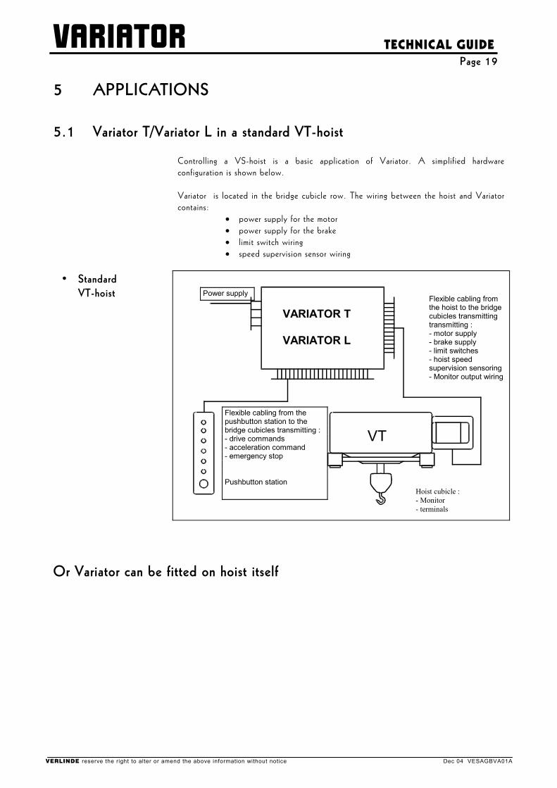
Controlling a VS-hoist is a basic application of Variator. A simplified hardware configuration is shown below.
Variator is located in the bridge cubicle row. The wiring between the hoist and Variator
contains: • power supply for the motor
• power supply for the brake • limit switch wiring • speed supervision sensor wiring
• Standard
VT-hoist
VARIATOR T VARIATOR L
VT
Flexible cabling from the hoist to the bridge cubicles transmitting transmitting : - motor supply - brake supply - limit switches - hoist speed supervision sensoring- Monitor output wiring
Hoist cubicle : - Monitor - terminals
Flexible cabling from the pushbutton station to the bridge cubicles transmitting : - drive commands - acceleration command - emergency stop Pushbutton station
Power supply
Or Variator can be fitted on hoist itself
VERLINDE reserve the right to alter or amend the above information without notice Dec 04 VESAGBVA01A
VARIATOR
TECHNICAL GUIDE Page 20
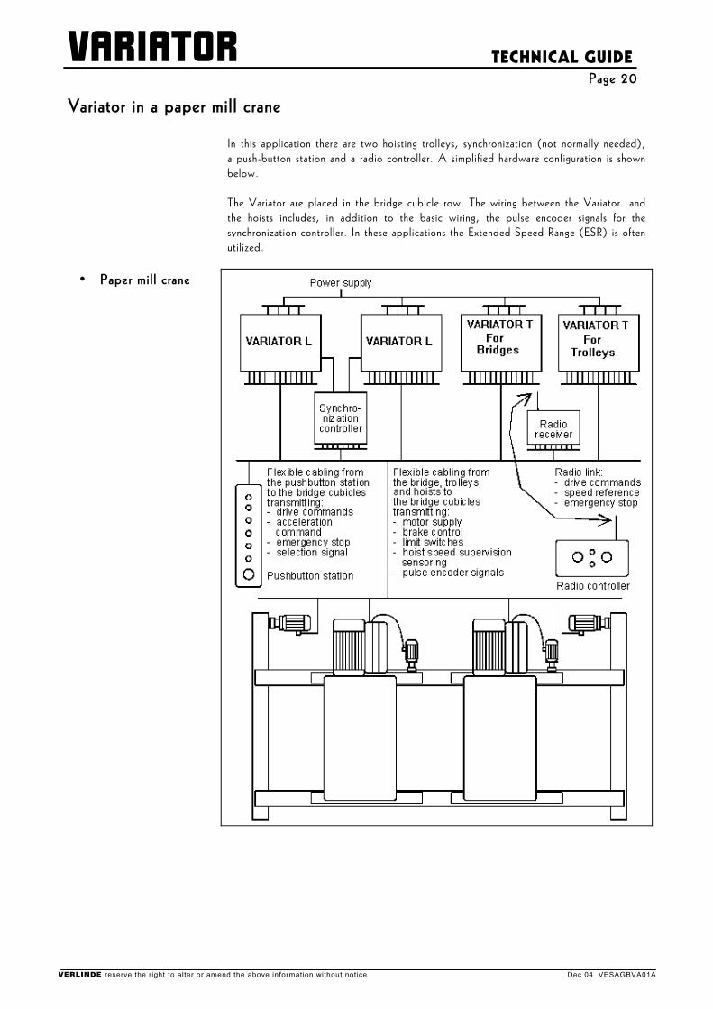
Variator in a paper mill crane
In this application there are two hoisting trolleys, synchronization (not normally needed), a push-button station and a radio controller. A simplified hardware configuration is shown below.
The Variator are placed in the bridge cubicle row. The wiring between the Variator and
the hoists includes, in addition to the basic wiring, the pulse encoder signals for the synchronization controller. In these applications the Extended Speed Range (ESR) is often utilized.
• Paper mill crane
VERLINDE reserve the right to alter or amend the above information without notice Dec 04 VESAGBVA01A
VARIATOR
TECHNICAL GUIDE Page 21
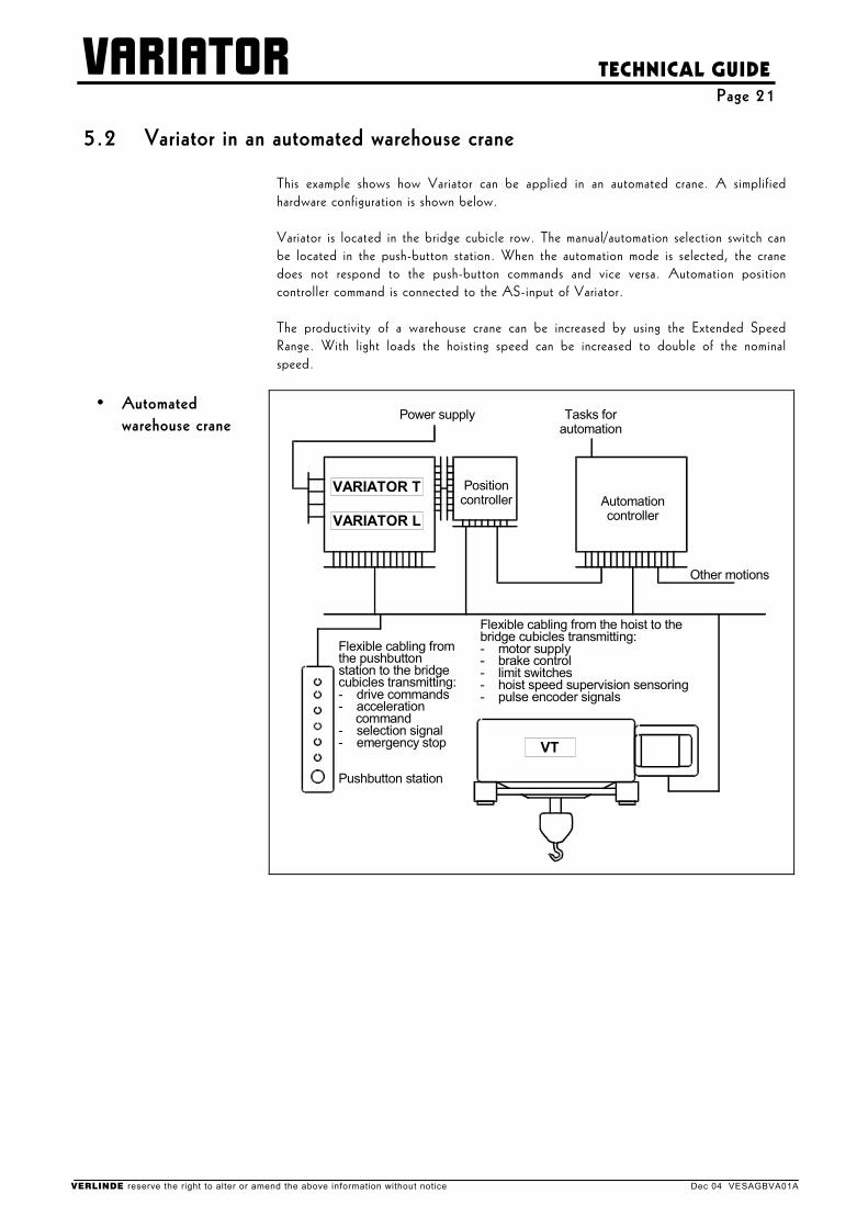
5.2 Variator in an automated warehouse crane
This example shows how Variator can be applied in an automated crane. A simplified hardware configuration is shown below.
Variator is located in the bridge cubicle row. The manual/automation selection switch can
be located in the push-button station. When the automation mode is selected, the crane does not respond to the push-button commands and vice versa. Automation position controller command is connected to the AS-input of Variator.
The productivity of a warehouse crane can be increased by using the Extended Speed
Range. With light loads the hoisting speed can be increased to double of the nominal speed.
• Automated
warehouse crane
A u t o m a t i o n c o n t r o l l e r
P o s i t i o n c o n t r o l l e r
P o w e r s u p p l y T a s k s f o r a u t o m a t i o n
O t h e r m o t i o n s
F l e x i b l e c a b l i n g f r o m t h e p u s h b u t t o n s t a t i o n t o t h e b r i d g e c u b i c l e s t r a n s m i t t i n g : - d r i v e c o m m a n d s - a c c e l e r a t i o n c o m m a n d - s e l e c t i o n s i g n a l - e m e r g e n c y s t o p
P u s h b u t t o n s t a t i o n
F l e x i b l e c a b l i n g f r o m t h e h o i s t t o t h e b r i d g e c u b i c l e s t r a n s m i t t i n g : - m o t o r s u p p l y - b r a k e c o n t r o l - l i m i t s w i t c h e s - h o i s t s p e e d s u p e r v i s i o n s e n s o r i n g - p u l s e e n c o d e r s i g n a l s
VARIATOR T
VARIATOR L
VT
VERLINDE reserve the right to alter or amend the above information without notice Dec 04 VESAGBVA01A

VARIATOR
TECHNICAL GUIDE Page 22
6 TERMINOLOGY OF VARIATOR
• Frequency control A frequency control system or in short, a frequency control is a complete control system for one crane motion. In addition to the inverter, it includes several components and functions: • The line contactor enables to disconnect the inverter from the power supply in case of
any fault. • The brake contactor is needed to control the electromechanical brake of the machinery
- with the capability to handle also the emergency situations. • The motor thermal protection is a must ; Variator provides the most reliable
protection, by measuring the motor temperature with a built-in thermistor relay. • The electrical braking circuitry of Variator is designed and dimensioned for crane
applications. • The two-step limit switch functions enable a safe operation even if the operator does
not notice the limits of the crane operating area. • The user interface is designed for crane applications, including both the necessary
functions and the suitable hardware for the harsh environment. • The mechanical construction including cooling considerations and the protection against
the environment is designed for crane applications. • The speed supervision unit is included in Variator L ; a speed sensor is added to the
machinery and the supervision function is independent of the inverter with a fail-to-safe design.
• Inverter VERLINDE-inverter is a part of Variator. The main circuitry of the inverter is to manipulate the line voltage so that the motor is all the time supplied with an optimal voltage. The control electronics of the inverter can be divided into three functional parts : • The power electronics components in the main circuitry are controlled by the power
drive circuitry, which also includes the self-protection functions for the hardware itself. • The motor control electronics is the core of the system. It receives commands from the
user interface and data on the actual operating condition. Based on this information, the motor control determines correct reference signals to the power drive circuitry.
• The user interface, or application interface, includes the display panel for drive monitoring and adjustments as well as the handling of the electrical analog and digital signals from the crane operator and the sensors.
Note, that both the control software and the hardware of most general purpose inverters, which are standard inverters not specifically designed for cranes, do not fulfill the needs of crane applications without modifications.
VERLINDE reserve the right to alter or amend the above information without notice Dec 04 VESAGBVA01A
VARIATOR
TECHNICAL GUIDE Page 23
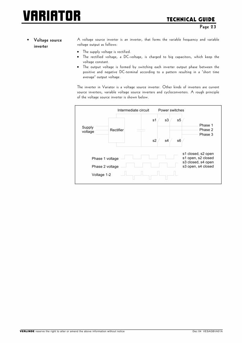
• Voltage source inverter
A voltage source inverter is an inverter, that forms the variable frequency and variable voltage output as follows:
• The supply voltage is rectified. • The rectified voltage, a DC-voltage, is charged to big capacitors, which keep the
voltage constant. • The output voltage is formed by switching each inverter output phase between the
positive and negative DC-terminal according to a pattern resulting in a "short time average" output voltage.
The inverter in Variator is a voltage source inverter. Other kinds of inverters are current
source inverters, variable voltage source inverters and cycloconverters. A rough principle of the voltage source inverter is shown below.
Rectifier
Power switches
s1
s2
s3
s4
s5
s6
s1 closed, s2 opens1 open, s2 closeds3 closed, s4 opens3 open, s4 closed
Phase 1 voltage
Phase 1Supplyvoltage
Intermediate circuit
Phase 2 voltage
Voltage 1-2
Phase 2Phase 3
VERLINDE reserve the right to alter or amend the above information without notice Dec 04 VESAGBVA01A
VARIATOR
TECHNICAL GUIDE Page 24
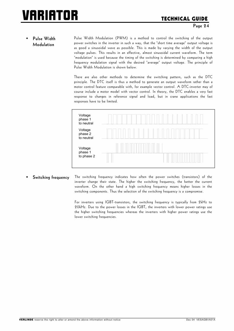
• Pulse Width Modulation
Pulse Width Modulation (PWM) is a method to control the switching of the output power switches in the inverter in such a way, that the "short time average" output voltage is as good a sinusoidal wave as possible. This is made by varying the width of the output voltage pulses. This results in an effective, almost sinusoidal current waveform. The term "modulation" is used because the timing of the switching is determined by comparing a high frequency modulation signal with the desired "average" output voltage. The principle of Pulse Width Modulation is shown below. There are also other methods to determine the switching pattern, such as the DTC principle. The DTC itself is thus a method to generate an output waveform rather than a motor control feature comparable with, for example vector control. A DTC-inverter may of course include a motor model with vector control. In theory, the DTC enables a very fast response to changes in reference signal and load, but in crane applications the fast responses have to be limited.
Voltagephase 1to phase 2
Voltagephase 2to neutral
Voltagephase 1to neutral
• Switching frequency The switching frequency indicates how often the power switches (transistors) of the inverter change their state. The higher the switching frequency, the better the current waveform. On the other hand a high switching frequency means higher losses in the switching components. Thus the selection of the switching frequency is a compromise.
For inverters using IGBT-transistors, the switching frequency is typically from 2kHz to 20kHz. Due to the power losses in the IGBT, the inverters with lower power ratings use the higher switching frequencies whereas the inverters with higher power ratings use the lower switching frequencies.
VERLINDE reserve the right to alter or amend the above information without notice Dec 04 VESAGBVA01A
VARIATOR
TECHNICAL GUIDE Page 25
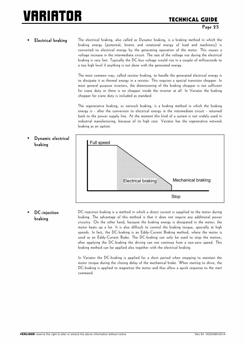
• Electrical braking The electrical braking, also called as Dynamic braking, is a braking method in which the braking energy (potential, kinetic and rotational energy of load and machinery) is converted to electrical energy by the generating operation of the motor. This causes a voltage increase in the intermediate circuit. The rate of the voltage rise during the electrical braking is very fast. Typically the DC-bus voltage would rise in a couple of milliseconds to a too high level if anything is not done with the generated energy. The most common way, called resistor braking, to handle the generated electrical energy is to dissipate it as thermal energy in a resistor. This requires a special transistor chopper. In most general purpose inverters, the dimensioning of the braking chopper is not sufficient for crane duty or there is no chopper inside the inverter at all. In Variator the braking chopper for crane duty is included as standard. The regenerative braking, or network braking, is a braking method in which the braking energy is - after the conversion to electrical energy in the intermediate circuit - returned back to the power supply line. At the moment this kind of a system is not widely used in industrial manufacturing, because of its high cost. Variator has the regenerative network braking as an option.
• Dynamic electrical braking Full speed
Electrical braking
Stop
Mechanical braking
• DC-injection braking
DC-injection braking is a method in which a direct current is supplied to the motor during braking. The advantage of this method is that it does not require any additional power circuitry. On the other hand, because the braking energy is dissipated in the motor, the motor heats up a lot. It is also difficult to control the braking torque, specially at high speeds. In fact, the DC-braking is an Eddy-Current Braking method, where the motor is used as an Eddy-Current Brake. The DC-braking can only be used to stop the motion, after applying the DC-braking the driving can not continue from a non-zero speed. This braking method can be applied also together with the electrical braking. In Variator the DC-braking is applied for a short period when stopping to maintain the motor torque during the closing delay of the mechanical brake. When starting to drive, the DC-braking is applied to magnetize the motor and thus allow a quick response to the start command.
VERLINDE reserve the right to alter or amend the above information without notice Dec 04 VESAGBVA01A
VARIATOR
TECHNICAL GUIDE Page 26
• Flux braking The flux braking is a method where the motor is supplied with AC-current by overmagnetizing the motor. Then, the generated energy is dissipated by the motor. The advantage of this method is that it does not require any additional power circuitry. On the other hand, because the braking energy is dissipated in the motor, the motor heats up a lot. The flux braking is not applicable in crane drives, because typically only about 20 % braking torque can be reached. This braking method is not applied in Variator.
• Torque compensation
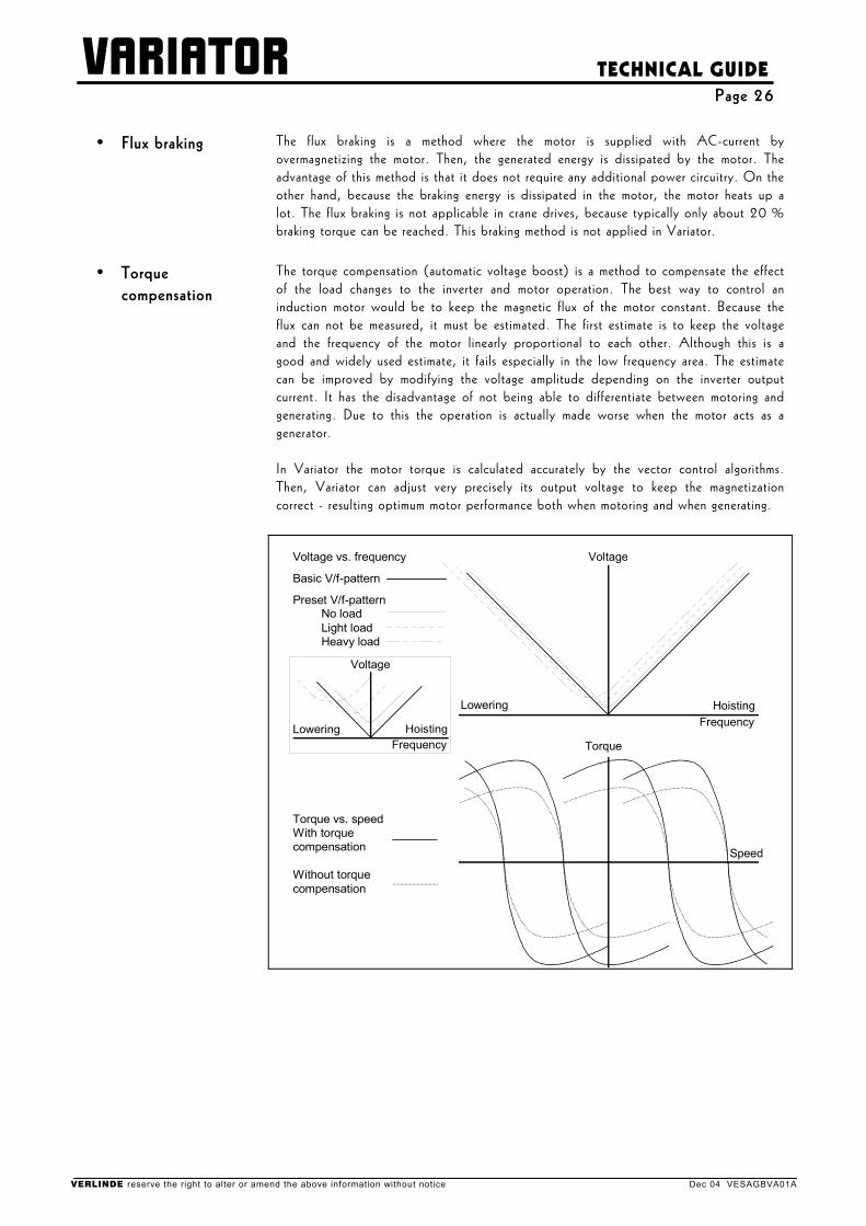
The torque compensation (automatic voltage boost) is a method to compensate the effect of the load changes to the inverter and motor operation. The best way to control an induction motor would be to keep the magnetic flux of the motor constant. Because the flux can not be measured, it must be estimated. The first estimate is to keep the voltage and the frequency of the motor linearly proportional to each other. Although this is a good and widely used estimate, it fails especially in the low frequency area. The estimate can be improved by modifying the voltage amplitude depending on the inverter output current. It has the disadvantage of not being able to differentiate between motoring and generating. Due to this the operation is actually made worse when the motor acts as a generator. In Variator the motor torque is calculated accurately by the vector control algorithms. Then, Variator can adjust very precisely its output voltage to keep the magnetization correct - resulting optimum motor performance both when motoring and when generating.
Lowering
Torque
HoistingFrequency
Speed
Voltage vs. frequency
Basic V/f-pattern
Preset V/f-pattern No load Light load Heavy load
Torque vs. speedWith torquecompensation
Without torquecompensation
Voltage
Lowering HoistingFrequency
Voltage
VERLINDE reserve the right to alter or amend the above information without notice Dec 04 VESAGBVA01A
VARIATOR
TECHNICAL GUIDE Page 27
• Stall protection With direct-starting motor drives, the term stall has been applied both in situations where either the motor's starting torque (locked rotor torque) is not sufficient to overcome the load torque or when during running the load torque exceeds the motor's pull-out torque. With inverter based drives, the term stall protection means rather a function to avoid exceeding the capacity of the inverter due to the increase of motor load. Exceeding the inverter's capacity would cause the inverter to trip, and as the result of this the motor would "stall". The stall situations with inverter based drives can be divided as follows: • Stall at start; the load is so heavy that the motor can not start rotating. • Stall during acceleration; the torque needed to carry out the desired acceleration is so
high that the motor current exceeds the allowable limits. • Stall during operation; when the motor is running the load increases so much that the
motor current exceeds the allowable limits. • Stall during deceleration and generating; the braking torque is so high that either the
motor current exceeds the allowable limits or the intermediate circuit voltage increases too much.
In many applications stall can be prevented by modifying the output frequency in a suitable manner, for example the stall during acceleration can usually be prevented by reducing the increase rate of the motor frequency. In crane applications, specially in hoisting, with a proper device dimensioning the stall prevention functions are not needed. The protection has an effect only at some fault, like during a mechanical jam. The stall protection in Variator covers all stall situations except the stall during deceleration and generating. This stall situation could only be avoided either by extending the deceleration time or by letting the speed increase, which may cause dangerous situations, this is why the protection is not available in Variator.
VERLINDE reserve the right to alter or amend the above information without notice Dec 04 VESAGBVA01A
VARIATOR
TECHNICAL GUIDE Page 28
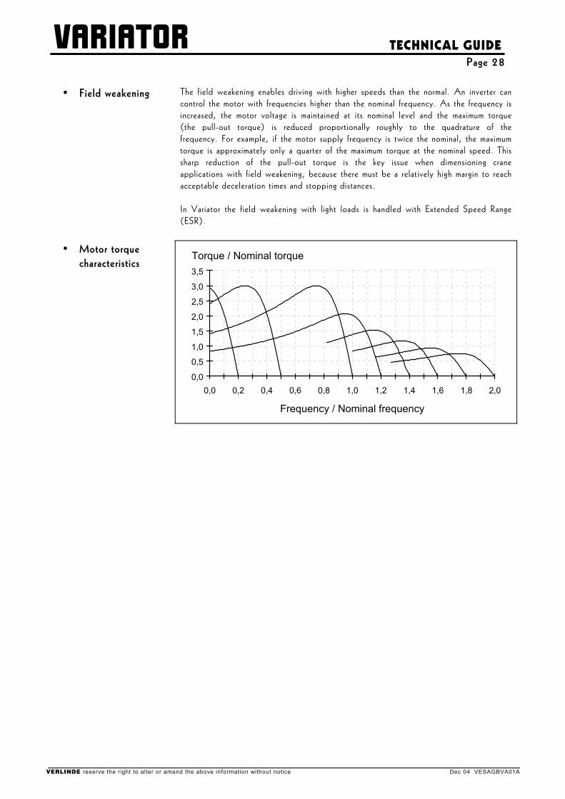
• Field weakening The field weakening enables driving with higher speeds than the normal. An inverter can control the motor with frequencies higher than the nominal frequency. As the frequency is increased, the motor voltage is maintained at its nominal level and the maximum torque (the pull-out torque) is reduced proportionally roughly to the quadrature of the frequency. For example, if the motor supply frequency is twice the nominal, the maximum torque is approximately only a quarter of the maximum torque at the nominal speed. This sharp reduction of the pull-out torque is the key issue when dimensioning crane applications with field weakening, because there must be a relatively high margin to reach acceptable deceleration times and stopping distances. In Variator the field weakening with light loads is handled with Extended Speed Range (ESR).
• Motor torque characteristics
0,0
0,5
1,0
1,5
2,0
2,5
3,0
3,5
0,0 0,2 0,4 0,6 0,8 1,0 1,2 1,4 1,6 1,8 2,0
Frequency / Nominal frequency
Torque / Nominal torque
VERLINDE reserve the right to alter or amend the above information without notice Dec 04 VESAGBVA01A
VARIATOR
TECHNICAL GUIDE Page 29
• Ambient temperature
The ambient temperature is the temperature which the device "feels" to be in. For example, when Variator is installed in a cubicle, the ambient temperature of Variator is the internal temperature of the cubicle.
The allowed ambient conditions of Variator are specified as following : if the duty cycle is less or equal to 60% ED - as the crane duty usually is - the temperature range is -10...+55°C and humidity <95% RH. If the duty cycle is 100% ED, the maximum temperature is +40°C.
• EMC The abbreviation "EMC" stands for the ElectroMagnetic Compatibility. According to the EMC directive "the apparatus shall be so constructed that:
a) the electromagnetic disturbance it generates does not exceed a level allowing other apparatus to operate as intended
b) the apparatus has an adequate level of intrinsic immunity of electromagnetic disturbance to enable it to operate as intended."
The above requirement of the EMC directive can be met by conforming to the appropriate EMC standards. The EMC requirements (both for immunity and for emissions) for Variator are set in IEC 1800-3, which is the EMC product standard for "adjustable speed electrical power drive systems". The IEC 1800-3 is identical with EN 61800-3. The most commonly referred EMC standards are EN 50081 (for emission limits), EN 50082 (for immunity requirements) and IEC 1000-series. These are the generic standards to be applied if no applicable product standard exists. All Variator fulfill the immunity requirements defined in the IEC 1800-3 (EN 61800-3), both for "the first environment (household)" and for "the second environment (industry)". As EN 50082-1 and EN 50082-2 define equal requirements, also these requirements are met. All Variator fulfill the emission requirements of the EN 61800-3 for the second environment. For the first environment, depending on the device rated current, tighter emission limits shall be applied. In these cases, the use of E- or C-model Variator and/or special accessories (like filters, shielded cables) may be needed.
VERLINDE reserve the right to alter or amend the above information without notice Dec 04 VESAGBVA01A