Embed Size (px)
Citation preview

GUIDE TO MODEL SPECIFICATION – CHANCE® Civil Construction
HELICAL PILES FOR STRUCTURAL SUPPORT
TYPES OF SPECIFICATIONS
The three types of specifications that are used for Helical Pile projects are:
Open Specifications: The Contractor is given the responsibility for the scope and design of the Helical Pile installation. In addition, the construction, capacity, and performance of the Helical Pile are the sole responsibility of the Contractor. This specification assumes that the Owner or Designer has provided the required structural loads. This specification type is most common for securing bids on temporary projects, and is not recommended for permanent applications.
Performance Specifications: The Contractor is given the responsibility for certain design and/or construction procedures, but must demonstrate to the Owner through testing and/or mutually agreed upon acceptance criteria that the production Helical Piles meet or exceed the specified performance parameters. This specification assumes that the location and the required loads of the Helical Pile have been specified. The Contractor and Owner share the responsibility for the work.
Prescriptive Specifications: The Owner has the sole responsibility for the scope and design of the Helical Pile installation and specifies the procedures that must be followed. Prescriptive specifications mandate the Owner to be responsible for the proper performance of the Helical Piles. The Contractor is responsible for fulfilling the obligations/details as specified in the construction documents.
Performance specifications are the most common and allow Contractors to use their unique installation methods and experience for any given site conditions. Owners receive the benefit of value engineering, which can result in lower costs.
The Owner, Designer, and Contractor will be jointly responsible for the design, installation, acceptance, and performance of Helical Piles. The installation of a Helical Pile requires specialized equipment, techniques, and trained work crews. Every detail of the work cannot be specified, and every potential problem cannot be anticipated. Therefore, a contractor trained in the proper methods of design and installation of Helical Piles must be selected.
A list of the major tasks to be performed on a Helical Pile project is shown in Table-1 of the Model Specifications. The Owner or his representative should select the type of specification and procurement method. The responsible party for each task must be identified and mutually agreed upon at the earliest point in the contracting process. The completed Table-1 should be included in the construction documents.Guide to Model Specification –HELICAL PILES – Structural SupportA.B. Chance | A Division of Hubbell Power Systems ©Copyright 2005 Hubbell, Inc.
1

The process of continuous communication between all the parties involved is essential to achieve a satisfactory result. Clear communication and close cooperation are particularly important in the start-up phase and in testing. In addition, a timely preparation and review of all submittals is critical.
This model specification can be adapted to each of the three types of specifications. However, it is primarily written for the performance type. The identity of the “Contractor” and the “Owner” is always well defined, unlike that of the “Designer” or “Engineer”. For example, the “Engineer” may be an employee(s) of the Contractor, or a third party consultant hired to secure a lower cost alternative during the bidding process. In contrast, the “Engineer” may be the Owner, an employee(s) of the Owner, or a representative hired by the Owner. It is recommended that the Engineer be a third party agency employed by the Owner to serve in the owner’s best interests during the various stages of the contract.
For purposes of this Model Specification, the subject is a high capacity Helical Pile manufactured by CHANCE® Civil Construction. At present, maximum working or design loads range between 12.5 and 50 tons. The Helical Pile consists of one or more helical bearing plates attached at the tip of a high strength central steel shaft. The central steel shaft consists of either a solid square shaft of various sizes, or hollow pipe shaft of various diameters and wall thickness. The steel shafts are typically 1-1/2” to 8 inches in diameter and will accept load directly axially and/or laterally to provide structural support.
It is suggested that the specification writer accurately and completely modify this model to suit his/her particular case.Items in italics as such may be considered as “Commentary” and as such may be deleted or retained to suit the needs of the specification writer.
Guide to Model Specification –HELICAL PILES – Structural SupportA.B. Chance | A Division of Hubbell Power Systems ©Copyright 2005 Hubbell, Inc.
2
The following is list of general references that will provide additional background to Helical Pile technology:
A. B. Chance Company, HELICAL PIER® Foundation Systems, Technical Manual, Bulletin 01-9601, Copyright 2000 Hubbell, 210 North Allen St., Centralia, MO 65240
A. B. Chance Company, Helical Screw Foundations – Design Manual for New Construction, Copyright 2003 A.B. Chance Company, 210 North Allen St., Centralia, MO 65240
Atlas Systems, Inc., Technical Manual, 2005, Copyright 2004 – Atlas Systems, Inc, 1026-B South Powell Road, Independence, MO 64056
“BOCA Research Report 94-27”, Copyright 1996, BOCA Evaluation Services, Inc., Country Club Hills, IL 60478
Goen, J. Lee, Compression Load on HELICAL PIER® Foundation Systems Anchors – Design and Construction, Bulletin 01-9304, Copyright 1998 Hubbell/Chance, 210 North Allen St., Centralia, MO 65240
Hargrave, R. L. and Thorsten, R. E., 1992. Helical Piers in Expansive Soils of Dallas, Texas. Proceedings 7 th
International Conference on Expansive Soils, Session 24, Bulletin 01-9311, Copyright 1993 A. B. Chance, 210 North Allen St., Centralia, MO 65240 Hoyt, R.M. and Clemence, S.P., 1989. Uplift Capacity of Helical Anchors in Soil. Proceedings of the 12th International Conference on Soil Mechanics and Foundation Engineering, Vol. 2, pp. 1019-1022.
“ICBO Evaluation Report - ER-5110”, Copyright 2001, ICBO Evaluation Service, Inc., Whittier, CA 90601
Pack, J. S., 2000. Design of Helical Piles for Heavily Loaded Structures. New Technological and Design Developments in Deep Foundations, ASCE Geotechnical Special Publication, pp. 353- 367.
“SBCCI Report No. 9504B”, Copyright 1999, SBCCI Public Safety Testing and Evaluation Services Inc., Birmingham, AL 35213
Seider, Gary L., “Versatile Steel Screw Anchors”, Structural Engineer Magazine, March 2000; Volume 1, Number 2, ppgs. 42-46.
Wesolek, Dana A., Schmednecht, Fred C., and Seider, Gary L. “Helical Piers/Anchors in the Chicago Building Code”, Proceedings of the DFI 30th Annual Conference on Deep Foundations, Chicago, IL pp. 193-204.
Guide to Model Specification –HELICAL PILES – Structural SupportA.B. Chance | A Division of Hubbell Power Systems ©Copyright 2005 Hubbell, Inc.
3

CHANCE® Civil Construction HELICAL PILES
MODEL SPECIFICATION
1. GENERAL
1.1 Purpose of Specification
The purpose of this specification is to detail the furnishing of all designs, materials, tools, equipment, labor and supervision, and installation techniques necessary to install Helical Piles as detailed on the drawings, including connection details. This shall include provisions for load testing that may be part of the scope of work
Specifier Note: This specification may require modification to account for unusual and/or unforeseen site and subsurface conditions and the particular circumstances of the project.
1.2 Scope of Work
This work consists of furnishing all necessary engineering and design services (if required), supervision, labor, tools, materials, and equipment to perform all work necessary to install the Helical Piles, at (location, City, State/Province) for (Company, State or Private Authority) per the specifications described herein, and as shown on the drawings. The Contractor shall install a Helical Pile that will develop the load capacities as detailed on the drawings. This may also include provisions for load testing to verify Helical Pile capacity and deflection, if part of the scope of work. The responsibilities and duties of the respective parties for this project are summarized in Table-1.
Guide to Model Specification –HELICAL PILES – Structural SupportA.B. Chance | A Division of Hubbell Power Systems ©Copyright 2005 Hubbell, Inc.
4
Table-1. Tasks and Responsibilities to be Allocated for Helical Pile Work
TASK RESPONSIBLE PARTY*
1 Site Investigation, Geotechnical Investigation, Site Survey, and potential work restrictions
2 Type of specification, requirement for a pre-contract testing program, and procurement method
3 Obtaining easements4 Overall scope of work, design of the Helical Pile structure – including
design loads (vertical, horizontal, etc.), pile locations, and pile spacing and orientation
5 Definition and qualification of safety factors6 Calculation/estimation of allowable structural and/or Helical Pile
movement in service (acceptance criteria)7 Definition of service life (temporary – months or permanent - years) and
required degree of corrosion protection based on site conditions8 Type and number of tests (pre-contract, pre-production and production)9 Minimum total Helical Pile length, depth to bearing stratum10 Helical Pile components and details11 Details of corrosion protection, if required12 Details of pile connection to structure (e.g., for static and seismic
conditions)13 Preparation of Drawings and test reports14 Evaluation of test results15 Construction methods, schedule, sequencing, and coordination of work16 Requirements of field production control, including logging of installation
torque vs. installed depth17 Supervision of work18 Long-term monitoring* To be filled in by specification writer.
1.3 Qualifications of the Helical Pile Contractor
The Helical Pile Contractor shall be experienced in performing design and construction of Helical Piles and shall furnish all materials, labor, and supervision to perform the work. The Contractor shall be trained and certified by CHANCE Civil Construction in the proper methods of design and installation of Helical Piles. The Contractor shall provide names of on-site personnel materially involved with the work, including those who carry documented certification from CHANCE Civil Construction. At a minimum, these personnel shall include foreman, machine operator, and project engineer/manager.
The Helical Pile Contractor shall not sublet the whole or any part of the contract without the express written permission of the Owner. Guide to Model Specification –HELICAL PILES – Structural SupportA.B. Chance | A Division of Hubbell Power Systems ©Copyright 2005 Hubbell, Inc.
5
1.4 Related Project Specifications
To be determined by the specification writer.
1.5 Definitions
A partial list follows. The Owner may wish to add other specific, project-related items.
Contractor: The person/firm responsible for performing the Helical Pile work.
Coupling: Central steel shaft connection means formed as integral part of the plain extension shaft material. For Type SS & RS Helical Piles, couplings are internal or external sleeves, or hot upset forged sockets.
Coupling Bolt(s): High strength, structural steel fasteners used to connect Helical Pile segments together. For Type SS segments, the coupling bolt transfers axial load. For Type RS segments, the coupling bolts transfer both axial and torsional forces.
Helical Extension: Helical Pile foundation component installed immediately following the lead or starter section, if required. This component consists of one or more helical plates welded to a central steel shaft of finite length. Function is to increase bearing area.
Helix Plate: Generally round steel plate formed into a ramped spiral. The helical shape provides the means to install the helical pile, plus the plate transfers load to soil in end bearing. Helix plates are available in various diameters and thickness.
HELICAL PULLDOWN® Micropile: A small diameter, soil displacement, cast-in-place Helical Pile, in which most of the applied load is resisted by the central steel shaft and steel reinforcement, if installed. Load transfer to soil is both end bearing and friction. United States Patent 5,707,180, Method and Apparatus for Forming Piles In-Situ. A.k.a. HPM.
Helical Pile: A bearing type foundation element consisting of a lead or starter section, helical extension (if so required by site conditions), plain extension section(s), and a pile cap. A.k.a. helical screw pile, screw pile, helical screw foundation.
Installation Torque(T): The resistance generated by a Helical Pile when installed into soil. The installation resistance is a function of the soil type, and size and shape of the various components of the Helical Pile.
Lead Section: The first Helical Pile foundation component installed into the soil, consisting of single or multiple helix plates welded to a central steel shaft. A.k.a. Starter Section.
Pile Cap: Connection means by which structural loads are transferred to the Helical Pile. The type of connection varies depending upon the requirements of the project and type of Helical Pile material used.
Guide to Model Specification –HELICAL PILES – Structural SupportA.B. Chance | A Division of Hubbell Power Systems ©Copyright 2005 Hubbell, Inc.
6

Round Shaft (RS): Round steel pipe central Shaft elements ranging in diameter from 2-7/8” to 10”. A.k.a. Hollow Shaft (Type HS), Type T/C, Type PIF.
Plain Extension: Central steel shaft segment without helix plates. It is installed following the installation of the lead section or helical extension (if used). The segments are connected with integral couplings and bolts. Plain extensions are used to extend the helix plates beyond the specified minimum depth and into competent load bearing stratum.
Safety Factor: The ratio of the ultimate capacity to the working or design load used for the design of any structural element.
Square Shaft (SS): Solid steel, round-cornered-Square central Shaft elements ranging in size from 1-1/4” to 2-1/4”. A.k.a. Type SQ.
Torque Strength Rating: The maximum torque energy that can be applied to the helical pile foundation during installation in soil, a.k.a. allowable, or safe torque.
1.6 Allowable Tolerances
The tolerances quoted in this section are suggested maximums. The actual values established for a particular project will depend on the structural application.
1.6.1 Centerline of Helical Piles shall not be more than 3 inches from indicated plan location.
1.6.2 Helical Pile plumbness shall be within 2 of design alignment.
1.6.3 Top elevation of Helical Pile shall be within +1 inch to –2 inches of the design vertical elevation.
1.7 Quality Assurance
1.7.1 Helical Piles shall be installed by authorized CHANCE Civil Construction certified Contractor. These Contractors shall have satisfied the certification requirements relative to the technical aspects of the product and installation procedures as therein specified. Certification documents shall be provided upon request to the Owner or their representative.
1.7.2 The Contractor shall employ an adequate number of skilled workers who are experienced in the necessary crafts and who are familiar with the specified requirements and methods needed for proper performance of the work of this specification.
1.7.3 All Helical Piles shall be installed in the presence of a designated representative of the Owner unless said representative informs the Contractor otherwise. The designated representative shall have the right of access to any and all field installation records and test reports.
Guide to Model Specification –HELICAL PILES – Structural SupportA.B. Chance | A Division of Hubbell Power Systems ©Copyright 2005 Hubbell, Inc.
7
1.7.4 Helical Pile components as specified therein shall be manufactured by a facility whose quality systems comply with ISO (International Organization of Standards) 9001 requirements. Certificates of Registration denoting ISO Standards Number shall be presented upon request to the Owner or their representative.
1.7.5 CHANCE Civil Construction provides a standard one-year warranty on materials and workmanship of the product. Any additional warranty provided by the Contractor shall be issued as an addendum to this specification.
1.7.6 Design of Helical Piles shall be performed by an entity as required in accordance with existing local code requirements or established local practices. This design work may be performed by a licensed professional engineer, a certified CHANCE Civil Construction Contractor, or designer depending upon local requirements or practices.
1.8 Design Criteria
1.8.1 Helical Piles shall be designed to meet the specified loads and acceptance criteria as shown on the drawings. The calculations and drawings required from the Contractor or Engineer shall be submitted to the Owner for review and acceptance in accordance to Section 3.1 “Construction Submittals”.
1.8.2 The allowable working load on the Helical Piles shall not exceed the following values:
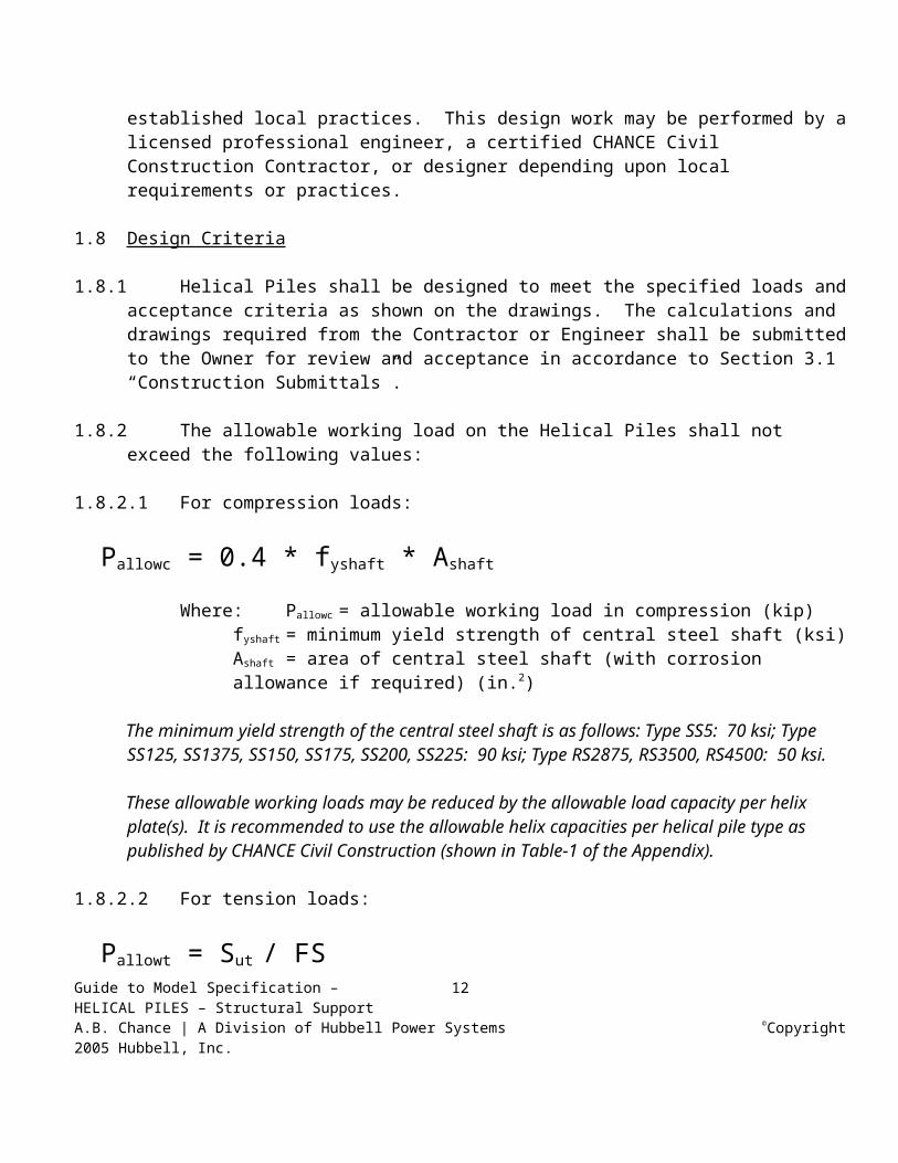
1.8.2.1 For compression loads:
Pallowc = 0.4 * fyshaft * Ashaft
Where:Pallowc = allowable working load in compression (kip)fyshaft = minimum yield strength of central steel shaft (ksi)Ashaft = area of central steel shaft (with corrosion allowance if required) (in.2)
The minimum yield strength of the central steel shaft is as follows: Type SS5: 70 ksi; Type SS125, SS1375, SS150, SS175, SS200, SS225: 90 ksi; Type RS2875, RS3500, RS4500: 50 ksi.
These allowable working loads may be reduced by the allowable load capacity per helix plate(s). It is recommended to use the allowable helix capacities per helical pile type as published by CHANCE Civil Construction (shown in Table-1 of the Appendix).
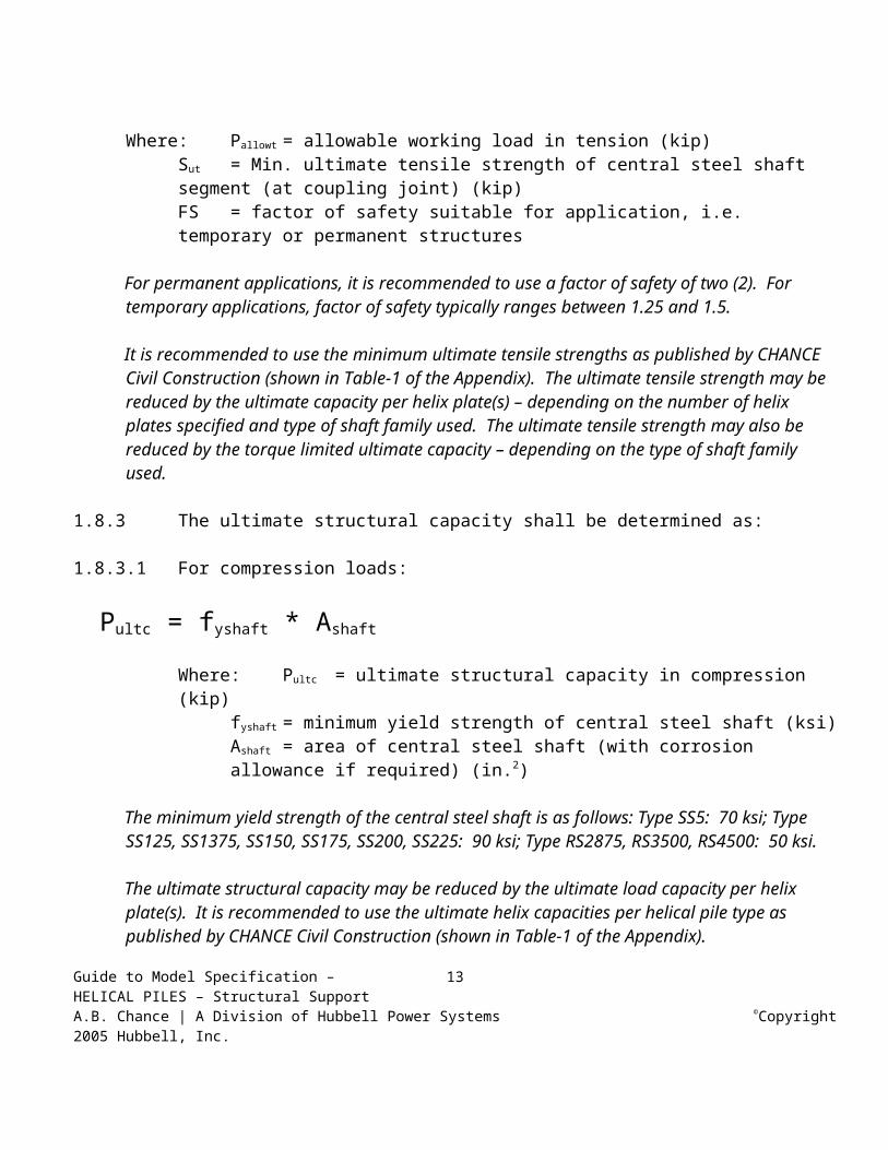
1.8.2.2 For tension loads:
Pallowt = Sut / FS
Where:Pallowt = allowable working load in tension (kip)Guide to Model Specification –HELICAL PILES – Structural SupportA.B. Chance | A Division of Hubbell Power Systems ©Copyright 2005 Hubbell, Inc.
8

Sut = Min. ultimate tensile strength of central steel shaft segment (at coupling joint) (kip)FS = factor of safety suitable for application, i.e. temporary or permanent structures
For permanent applications, it is recommended to use a factor of safety of two (2). For temporary applications, factor of safety typically ranges between 1.25 and 1.5.
It is recommended to use the minimum ultimate tensile strengths as published by CHANCE Civil Construction (shown in Table-1 of the Appendix). The ultimate tensile strength may be reduced by the ultimate capacity per helix plate(s) – depending on the number of helix plates specified and type of shaft family used. The ultimate tensile strength may also be reduced by the torque limited ultimate capacity – depending on the type of shaft family used.
1.8.3 The ultimate structural capacity shall be determined as:
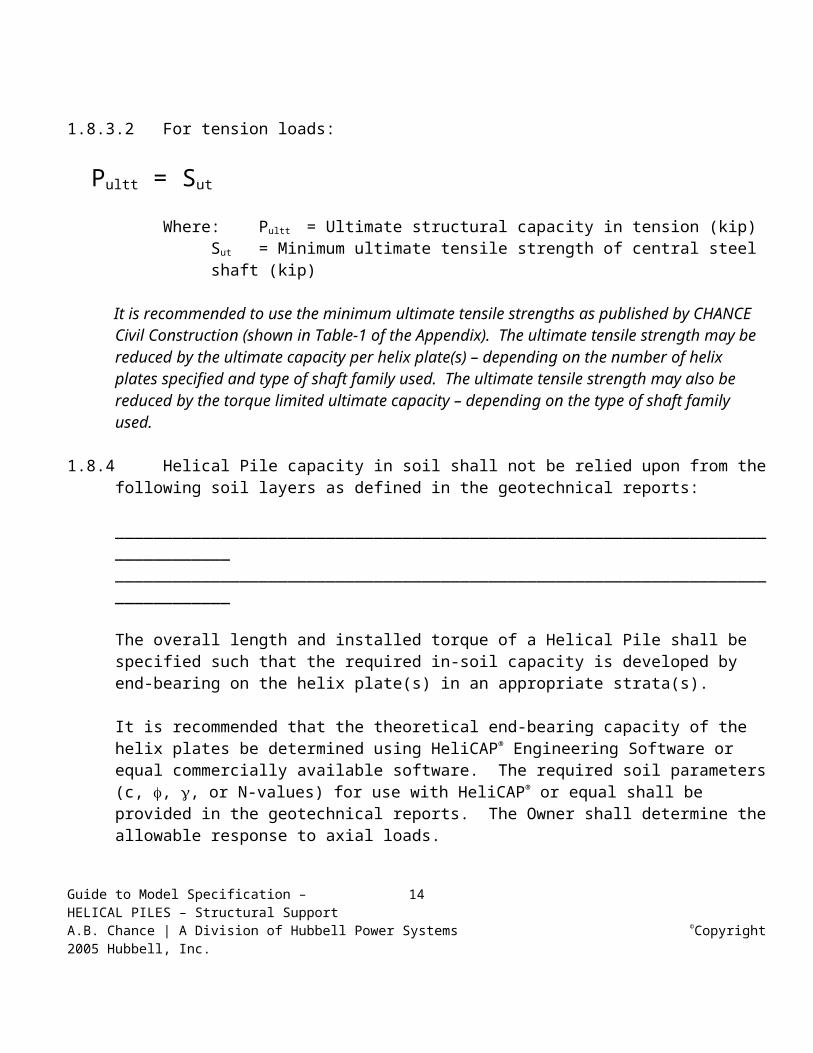
1.8.3.1 For compression loads:
Pultc = fyshaft * Ashaft
Where:Pultc = ultimate structural capacity in compression (kip)fyshaft = minimum yield strength of central steel shaft (ksi)Ashaft = area of central steel shaft (with corrosion allowance if required) (in.2)
The minimum yield strength of the central steel shaft is as follows: Type SS5: 70 ksi; Type SS125, SS1375, SS150, SS175, SS200, SS225: 90 ksi; Type RS2875, RS3500, RS4500: 50 ksi.
The ultimate structural capacity may be reduced by the ultimate load capacity per helix plate(s). It is recommended to use the ultimate helix capacities per helical pile type as published by CHANCE Civil Construction (shown in Table-1 of the Appendix).
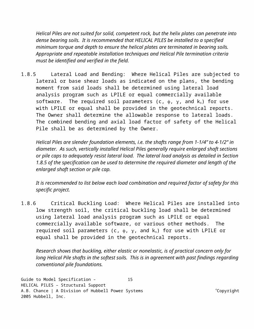
1.8.3.2 For tension loads:
Pultt = Sut
Where:Pultt = Ultimate structural capacity in tension (kip)Sut = Minimum ultimate tensile strength of central steel shaft (kip)
It is recommended to use the minimum ultimate tensile strengths as published by CHANCE Civil Construction (shown in Table-1 of the Appendix). The ultimate tensile strength may be reduced by the ultimate capacity per helix plate(s) – depending on the number of helix plates specified and type of shaft family used. The ultimate tensile strength may also be reduced by the torque limited ultimate capacity – depending on the type of shaft family used.
Guide to Model Specification –HELICAL PILES – Structural SupportA.B. Chance | A Division of Hubbell Power Systems ©Copyright 2005 Hubbell, Inc.
9

1.8.4 Helical Pile capacity in soil shall not be relied upon from the following soil layers as defined in the geotechnical reports:
________________________________________________________________________________________________________________________________________________________________
The overall length and installed torque of a Helical Pile shall be specified such that the required in-soil capacity is developed by end-bearing on the helix plate(s) in an appropriate strata(s).
It is recommended that the theoretical end-bearing capacity of the helix plates be determined using HeliCAP® Engineering Software or equal commercially available software. The required soil parameters (c, , , or N-values) for use with HeliCAP® or equal shall be provided in the geotechnical reports. The Owner shall determine the allowable response to axial loads.
Helical Piles are not suited for solid, competent rock, but the helix plates can penetrate into dense bearing soils. It is recommended that HELICAL PILES be installed to a specified minimum torque and depth to ensure the helical plates are terminated in bearing soils. Appropriate and repeatable installation techniques and Helical Pile termination criteria must be identified and verified in the field.
1.8.5 Lateral Load and Bending: Where Helical Piles are subjected to lateral or base shear loads as indicated on the plans, the bending moment from said loads shall be determined using lateral load analysis program such as LPILE or equal commercially available software. The required soil parameters (c, , , and ks) for use with LPILE or equal shall be provided in the geotechnical reports. The Owner shall determine the allowable response to lateral loads. The combined bending and axial load factor of safety of the Helical Pile shall be as determined by the Owner.
Helical Piles are slender foundation elements, i.e. the shafts range from 1-1/4” to 4-1/2” in diameter. As such, vertically installed Helical Piles generally require enlarged shaft sections or pile caps to adequately resist lateral load. The lateral load analysis as detailed in Section 1.8.5 of the specification can be used to determine the required diameter and length of the enlarged shaft section or pile cap.
It is recommended to list below each load combination and required factor of safety for this specific project.
1.8.6 Critical Buckling Load: Where Helical Piles are installed into low strength soil, the critical buckling load shall be determined using lateral load analysis program such as LPILE or equal commercially available software, or various other methods. The required soil parameters (c, , , and ks) for use with LPILE or equal shall be provided in the geotechnical reports.
Research shows that buckling, either elastic or nonelastic, is of practical concern only for long Helical Pile shafts in the softest soils. This is in agreement with past findings regarding conventional pile foundations.
Guide to Model Specification –HELICAL PILES – Structural SupportA.B. Chance | A Division of Hubbell Power Systems ©Copyright 2005 Hubbell, Inc.
10
1.8.7 Expansive Soils: Helical Pile used in areas where expansive soils are present may require the use of special construction methods to mitigate possible shrink/swell effects. Helical Pile shafts should be isolated from the concrete footing if said footing is in contact with the expansive soil.
1.8.8 Down-Drag/Negative Skin Friction: Type SS and Type RS Helical Piles are slender shaft foundation elements and are not practically affected by down-drag/negative skin friction. If Helical Piles with central steel shafts >4” in diameter are used in areas where compressible or decomposing soils overlie bearing stratum, or where expansive or frozen soils can cause pile jacking, Helical Pile shafts should be provided with a no-bond zone along a specified length to prevent load transfer that may adversely affect pile capacity. Alternately, Helical Piles can be provided with sufficient axial load capacity to resist down drag/negative skin friction forces.
1.8.9 The Helical Pile attachment (pile cap) shall distribute the design load (DL) to the concrete foundation such that the concrete bearing stress does not exceed those in the ACI Building Code and the stresses in the steel plates/welds does not exceed AISC allowable stresses for steel members.
1.8.10 Corrosion Protection
This section is optional (see below). Provisions of this section and Section 4.6 below may not be required in the Specification. If this section is not used, then Section 4.6 should likewise be deleted. The degree and extent of corrosion protection must be specified by the Owner (Table-1).
Corrosion protection is a function of structure type, service life, and the overall aggressiveness of the project soils. The need for corrosion protection of Helical Piles must be carefully determined and specified as necessary.
Corrosion resistant coatings (i.e. epoxy, plastic sheath) on the lead/starter section are impractical due to abrasive action wearing off the coating as the soil flows over the helix plates and around the central steel shaft. Hot dip galvanization is the only practical means to provide a corrosion resistant coating capable of withstanding the rigors of installation. Extension sections are typically hot-dip galvanized, but other coatings can be specified.
The following requirements are typical. The specifier should review and edit as appropriate for the project.
Structure Type: _________________________ (e.g. temporary, permanent) with a temporary structure being defined within a specified time frame (i.e. months rather than years). In general, permanent structures have a service life greater than 24 months.
Temporary structures do not require corrosion protection.
Guide to Model Specification –HELICAL PILES – Structural SupportA.B. Chance | A Division of Hubbell Power Systems ©Copyright 2005 Hubbell, Inc.
11
Service Life: ____________________________(years) a typical service life of 50 years should be used unless otherwise specified. If the service life of a temporary Helical Pile is likely to be extended due to construction delays, it should be considered permanent.
For a service life of less than 20 years in non-aggressive soil, corrosion protection is not recommended.
Corrosion protection requirements for the various Helical Pile elements shall be provided meeting the requirements of Table-2 in the Appendix for:
Soil: ____________________________________ Aggressive or Non-Aggressive with optional location and elevation limits defined by the Specifier.
For guidance on aggressiveness classification, see Table-2 in the Appendix. It is recommended to retain the services of a corrosion design professional for very aggressive soils.
TABLE-2CORROSION PROTECTION
LOADING TENSION COMPRESSIONSOIL AGGRESSIVE1 NON-
AGGRESSIVEAGGRESSIVE1 NON-
AGGRESSIVECENTRAL STEEL SHAFT (Lead Section)
a. GalvanizationOR
b. Minimum 1/8” corrosion loss on outside
a. Bare steelOR
b. GalvanizationOR
c. Minimum 1/8” corrosion loss on outside
a. GalvanizationOR
b. Minimum 1/8” corrosion loss on outside
a. Bare steelOR
b. GalvanizationOR
c. Minimum 1/8” corrosion loss on outside
CENTRAL STEEL SHAFT (Extension Section)
a. GalvanizationOR
b. Epoxy coatingOR
c. a. or b. + Grout cover2
The Specifier may elect to use a grout case.
a. Bare steelOR
b. GalvanizationOR
c. Epoxy coating
a. GalvanizationOR
b. Epoxy coatingOR
c. a. or b. + Grout cover2
The Specifier may elect to use a grout case.
a. Bare steelOR
b. GalvanizationOR
c. Epoxy coating
STEEL PILE CAP
a. GalvanizationOR
b. Epoxy coating
d. Bare steelOR
e. GalvanizationOR
f. Epoxy coating
c. GalvanizationOR
d. Epoxy coating
g. Bare steelOR
h. GalvanizationOR
i. Epoxy coating
Guide to Model Specification –HELICAL PILES – Structural SupportA.B. Chance | A Division of Hubbell Power Systems ©Copyright 2005 Hubbell, Inc.
12
NOTES:Lettered items are options.For guidance on aggressiveness classification, see Table-2 of the Appendix.1. Corrosion protection shall extend 15’-0 below corrosive material.2. Minimum 1” in soil. If protective coatings (galvanization, epoxy) are provided in compression,
minimum cover may be 0.25” in soil. Grout column can be installed using the patented HELICAL PULLDOWN® Micropile method.
The most critical area to protect from corrosion is at or near the ground line – if the surficial soils have been disturbed. Undisturbed soils are deficient in oxygen a few feet below ground line or below the water table zone. Undisturbed soils typically result in steel piling not being appreciably affected by corrosion.
1.9. Ground Conditions
The Geotechnical Report, including logs of soil borings as shown on the boring location plan, shall be considered to be representative of the in-situ subsurface conditions likely to be encountered on the project site. Said Geotechnical Report shall be the used as the basis for Helical Pile design using generally accepted engineering judgement and methods.
If soil borings are not available, it is suggested to install a Helical Pile at various locations on the project site. Using the well-known installed torque vs. capacity attribute of helical piles, a presumptive soil profile can be generated.
The Geotechnical Report shall be provided for purposes of bidding. If during Helical Pile installation, subsurface conditions of a type and location are encountered of a frequency that were not reported, inferred and/or expected at the time of preparation of the bid, the additional costs required to overcome such conditions shall be considered as extras to be paid for.
All available information related to subsurface and general site conditions should be made available to all bidders at the time of bid preparation. It is not reasonable to expect bidders to conduct supplemental site investigations at their own risk and cost prior to bidding, unless the specific contract requirements call for it (Table-1) and provide for appropriate compensation. A mandatory site visit and pre-bid meeting should be held so that the details of the project and the specifications can be thoroughly discussed. These steps will help avoid technical and contractual problems developing during the execution of the work, and will help all parties manage their respective risk.
2 REFERENCED CODES AND STANDARDS
Standards listed by reference, including revisions by issuing authority, form a part of this specification section to the extent indicated. Standards listed are identified by issuing authority, authority abbreviation, designation number, title, or other designation established by issuing authority. Standards subsequently referenced herein are referred to by issuing authority abbreviation and standard designation. In case of conflict, the particular requirements of this specification shall prevail. The latest publication as of the issue of this specification shall govern, unless indicated otherwise.Guide to Model Specification –HELICAL PILES – Structural SupportA.B. Chance | A Division of Hubbell Power Systems ©Copyright 2005 Hubbell, Inc.
13
2.1 American Society for Testing and Materials (ASTM):2.1.1 ASTM A29/A29M Steel Bars, Carbon and Alloy, Hot-Wrought and Cold Finished.2.1.2 ASTM A36/A36M Structural Steel.2.1.3 ASTM A53 Pipe, Steel, Black and Hot-Dipped, Zinc-Coated Welded and Seamless.2.1.4 ASTM A153 Zinc Coating (Hot Dip) on Iron and Steel Hardware.2.1.5 ASTM A252 Welded and Seamless Steel Pipe Piles.2.1.6 ASTM A775 Electrostatic Epoxy Coating2.1.7 ASTM A193/A193M Alloy-Steel and Stainless Steel Bolting Materials for High Temperature
Service.2.1.8 ASTM A320/A320M Alloy-Steel Bolting Materials for Low Temperature Service.2.1.9 ASTM A325 Standard Specification for Structural Bolts, Steel, Heat Treated, 120/105 ksi Minimum
Tensile Strength.2.1.10 ASTM A500 Cold-Formed Welded and Seamless Carbon Steel Structural Tubing in Rounds and
Shapes.2.1.11 ASTM A513 Standard Specification for Electric Resistance Welded Carbon and Alloy Steel
Mechanical Tubing.2.1.12 ASTM A536 Standard Specifications for Ductile Iron Castings2.1.13 ASTM A572 HSLA Columbium-Vanadium Steels of Structural Quality.2.1.14 ASTM A618 Hot-Formed Welded and Seamless High-Strength Low-Alloy Structural Tubing.2.1.15 ASTM A656 Hot-Rolled Structural Steel, High-Strength Low-Alloy Plate with Improved
Formability.2.1.16 ASTM A958 Standard Specification for Steel Castings, Carbon, and Alloy, with Tensile
Requirements, Chemical Requirements Similar to Wrought Grades.2.1.17 ASTM A1018 Steel, Sheet and Strip, Heavy Thickness Coils, Hot Rolled, Carbon, Structural, High-
Strength Low-Alloy, Columbium or Vanadium, and High-Strength Low-Alloy with Improved Formability.
2.1.18 ASTM D1143 Method of Testing Piles Under Static Axial Compressive Load.2.1.19 ASTM D3689 Method of Testing Individual Piles Under Static Axial Tensile Load.
2.2 American Welding Society (AWS):2.2.1 AWS D1.1 Structural Welding Code – Steel.2.2.2 AWS D1.2 Structural Welding Code – Reinforcing Steel.
2.3 American Society of Civil Engineers (ASCE):2.3.1 ASCE 20-96 Standard Guidelines for the Design and Installation of Pile Foundations.
2.4 Deep Foundations Institute (DFI):2.4.1 Guide to Drafting a Specification for High Capacity Drilled and Grouted Micropiles for Structural
Support, 1st Edition, Copyright 2001 by the Deep Foundation Institute (DFI).
2.5 Society of Automotive Engineers (SAE):2.5.1 SAE J429 Mechanical and Material Requirements for Externally Threaded Fasteners.
Guide to Model Specification –HELICAL PILES – Structural SupportA.B. Chance | A Division of Hubbell Power Systems ©Copyright 2005 Hubbell, Inc.
14
3 SUBMITTALS
3.1 Construction Submittals3.1.1 The Contractor or Engineer shall prepare and submit to the Owner, for review and approval, working
drawings and design calculations for the Helical Piles intended for use at least 14 calendar days prior to planned start of construction (but note also Paragraph 3.1.8). All submittals shall be signed and sealed by a Registered Professional Engineer currently licensed in the State/Province of __________________________.
3.1.2 The Contractor shall submit a detailed description of the construction procedures proposed for use to the Owner for review. This shall include a list of major equipment to be used.
3.1.3 The Working Drawings shall include the following:
3.1.3.a Helical Pile number, location and pattern by assigned identification number3.1.3.b Helical Pile design load3.1.3.c Type and size of central steel shaft Type SS125 1-1/4” RCS, Type SS1375 1-3/8” RCS, SS5/SS150 – 1-1/2” RCS, Type SS175 – 1-3/4” RCS, Type SS200 – 2” RCS, Type SS225 – 2-1/4” RCS, Type RS2875 – 2-7/8” OD, Type RS3500 – 3-1/2” OD Pipe, Type RS4500 – 4-1/2” OD Pipe.
3.1.3.d Helix configuration (number and diameter of helix plates)3.1.3.e Minimum effective installation torque3.1.3.f Minimum overall length3.1.3.g Inclination of Helical Pile3.1.3.h Cut-off elevation3.1.3.i Helical Pile attachment to structure relative to grade beam, column pad, pile cap, etc.
If the number of helix plates per Helical Pile required for the project is not shown on the Working Drawings, the Contractor shall have the option of performing subsurface tests using methods subject to the review and acceptance of the Owner. The data collected along with other information pertinent to the project site shall be used to determine the required helix configuration.
3.1.4 The Contractor shall submit shop drawings for all Helical Pile components, including corrosion protection and pile top attachment to the Owner for review and approval. This includes Helical Pile lead/starter and extension section identification (manufacturer’s catalog numbers).
Shop drawings for Helical Pile components, including pile top attachments, can be obtained from CHANCE Civil Construction, their certified Distributors and Installing Contractors, or directly from www.abchance.com or www.atlassys.com.
Guide to Model Specification –HELICAL PILES – Structural SupportA.B. Chance | A Division of Hubbell Power Systems ©Copyright 2005 Hubbell, Inc.
15
3.1.5 If required, the Contractor shall submit certified mill test reports for the central steel shaft, as the material is delivered, to the Owner for record purposes. The ultimate strength, yield strength, % elongation, and chemistry composition shall be provided.
3.1.6 The Contractor shall submit plans for pre-production (optional) and production testing for the Helical Piles to the Owner for review and acceptance prior to beginning load tests. The purpose of the test is to determine the load versus displacement response of the Helical Pile and provide an estimation of ultimate capacity.
It is the responsibility of the structural engineer of record to establish acceptance criteria for Helical Pile verification tests, which can be incorporated into the project specific specification. Load testing also provides the means to verify the empirical ratio between the ultimate capacity and the average installing torque of the Helical Pile for a specific project site.
3.1.7 The Contractor shall submit to the Owner copies of calibration reports for each torque indicator or torque motor, and all load test equipment to be used on the project. The calibration tests shall have been performed within forty five (45) working days of the date submitted. Helical Pile installation and testing shall not proceed until the Owner has received the calibration reports. These calibration reports shall include, but are not limited to, the following information:
3.1.7.a Name of project and Contractor3.1.7.b Name of testing agency3.1.7.c Identification (serial number) of device calibrated3.1.7.d Description of calibrated testing equipment3.1.7.e Date of calibration3.1.7.f Calibration data
Load test equipment includes load cylinders, pressure gauges, and load transducers. A. B. Chance Mechanical Dial Torque Indicator (SKU C303-1340) is calibrated prior to final assembly. Its torsion bar design eliminates the need for annual re-calibration. 3.1.8 Work shall not begin until all the submittals have been received and approved by the Owner. The
Contractor shall allow the Owner a reasonable time to review, comment, and return the submittal package after a complete set has been received. All costs associated with incomplete or unacceptable submittals shall be the responsibility of the Contractor.
3.2 Installation Records
The Contractor shall provide the Owner copies of Helical Pile installation records within 24 hours after each installation is completed. Records shall be prepared in accordance with the specified division of responsibilities as noted in Table-1. Formal copies shall be submitted on a weekly basis. These installation records shall include, but are not limited to, the following information.
3.2.1 Name of project and ContractorGuide to Model Specification –HELICAL PILES – Structural SupportA.B. Chance | A Division of Hubbell Power Systems ©Copyright 2005 Hubbell, Inc.
16
3.2.2 Name of Contractor’s supervisor during installation3.2.3 Date and time of installation3.2.4 Name and model of installation equipment3.2.5 Type of torque indicator used3.2.6 Location of Helical Pile by assigned identification number3.2.7 Actual Helical Pile type and configuration – including lead section (number and size of helix plates),
number and type of extension sections (manufacturer’s SKU numbers)3.2.8 Helical Pile installation duration and observations3.2.9 Total length of installed Helical Pile3.2.10 Cut-off elevation3.2.11 Inclination of Helical Pile3.2.12 Installation torque at one-foot intervals for the final 10 feet3.2.13 Comments pertaining to interruptions, obstructions, or other relevant information3.2.14 Rated load capacities
3.3 Test Reports
The Contractor shall provide the Owner copies of field test reports within 24 hours after completion of the load tests. Records shall be prepared in accordance with the specified division of responsibilities as noted in Table-1. Formal copies shall be submitted within a reasonable amount of time following test completion. These test reports shall include, but are not limited to, the following information (note Section 6 – Helical Pile Load Tests).
3.3.1 Name of project and Contractor3.3.2 Name of Contractor’s supervisor during installation3.3.3 Name of third party test agency, if required3.3.4 Date, time, and duration of test3.3.5 Location of Helical Pile by assigned identification number3.3.6 Type of test (i.e. tension or compression)3.3.7 Description of calibrated testing equipment and test set-up3.3.8 Actual Helical Pile type and configuration – including lead section, number and type of extension
sections (manufacturer’s SKU numbers)3.3.9 Steps and duration of each load increment3.3.10 Cumulative pile-head movement at each load step3.3.11 Comments pertaining to test procedure, equipment adjustments, or other relevant information3.3.12 Signed by third party test agency rep., registered professional engineer, or as required by local
jurisdiction
3.4 Closeout Submittals
3.4.1 Warranty: Warranty documents specified herein3.4.1.a Project Warranty: Refer to Conditions of the Contract for project warranty provisions
Coordinate the warranty period stated herein with the project warranty as stated in the Contract documents.Guide to Model Specification –HELICAL PILES – Structural SupportA.B. Chance | A Division of Hubbell Power Systems ©Copyright 2005 Hubbell, Inc.
17

Warranty Period: (Specify Term) years commencing on date of Substantial Completion
3.4.1.b Manufacturer’s Warranty: Submit, for Owner’s Acceptance, manufacturer’s standard warranty document executed by authorized company official. Manufacturer’s warranty is in addition to, and not a limitation of, other rights the Owner may have under Contract Document.
4 PRODUCTS AND MATERIALS
4.1 Central Steel Shaft:
The central steel shaft, consisting of lead sections, helical extensions, and plain extensions, shall be Type SS (Square Shaft) or RS (Round Shaft) or a combination of the two (SS to RS Combo Pile) as manufactured by CHANCE Civil Construction (Centralia and Independence, MO).
4.1.1 SS5 1-1/2” Material: Shall be hot rolled Round-Cornered-Square (RCS) solid steel bars meeting dimensional and workmanship requirements of ASTM A29. The bar shall be modified medium carbon steel grade (similar to AISI 1044) with improved strength due to fine grain size.
4.1.1.a Torque strength rating = 5,500 ft-lb4.1.1.b Minimum yield strength = 70 ksi
4.1.2 SS125 1-1/4”; SS1375 1-3/8”; SS150 1-1/2”; SS175 1-3/4; SS200 2”; SS225 2-1/4” Material: Shall be hot rolled Round-Cornered-Square (RCS) solid steel bars meeting the dimensional and workmanship requirements of ASTM A29. The bar shall be High Strength Low Alloy (HSLA), low to medium carbon steel grade with improved strength due to fine grain size.
4.1.2.a Torque strength rating: SS125 = 4,000 ft-lb; SS1375 = 5,500 ft-lb; SS150 = 7,000 ft-lb; SS175 = 11,000 ft-lb; SS200 = 16,000 ft-lb; SS225 = 23,000 ft-lb
4.1.2.b Minimum yield strength = 90 ksi
4.1.3 Type RS2875 2-7/8” OD Material: Structural steel tube or pipe, welded or seamless, in compliance with ASTM A500 or A513. Wall thickness is 0.165”, 0.203” or 0.262”.
4.1.3.a Torque strength rating: RS2875.165 = 4,500 ft-lb; RS2875.203 = 5,500 ft-lb; RS2875.262 = 7,500 ft-lb.
4.1.3.b Minimum yield strength = 50 ksi
4.1.4 Type RS3500 3-1/2” OD Material: Shall be structural steel tube or pipe, seamless or straight-seam welded, per ASTM A53, A252, ASTM A500, or ASTM A618. Wall thickness is 0.300” (schedule 80).
4.1.4.a Torque strength rating = 13,000 ft-lbGuide to Model Specification –HELICAL PILES – Structural SupportA.B. Chance | A Division of Hubbell Power Systems ©Copyright 2005 Hubbell, Inc.
18
4.1.4.b Minimum yield strength = 50 ksi
4.1.5 Type RS4500 4-1/2” OD Material: Shall be structural steel tube or pipe, seamless or straight-seam welded, per ASTM A500 or A513. Wall thickness is 0.337” (schedule 80).
4.1.5.a Torque strength rating = 23,000 ft-lb4.1.5.b Minimum yield strength = 50 ksi
4.1.6 SS to RS2875 Combo Pile Material: Shall be Type SS and RS2875 material as described above with a welded adapter for the transition from SS to RS2875.
4.1.7 SS to RS3500 Combo Pile Material: Shall be Type SS and RS3500 material as described above with a welded adapter for the transition from SS to RS3500.
4.1.8 SS to RS4500 Combo Pile Material: Shall be Type SS and RS4500 material as described above with a welded adapter for the transition from SS to RS4500.
4.2 Helix Bearing Plate:
Shall be hot rolled carbon steel sheet, strip, or plate formed on matching metal dies to true helical shape and uniform pitch. Bearing plate material shall conform to the following ASTM specifications.
4.2.1 SS5 Material: Per ASTM A572, or A1018, or A656 with minimum yield strength of 50 ksi. Plate thickness is 3/8”.
4.2.2 SS125 and SS1375 Material: Per ASTM A572 with minimum yield strength of 50 ksi. Plate thickness is 3/8” or ½”.
4.2.3 SS150 and SS175 Material: Per ASTM A656 or A1018 with minimum yield strength of 80 ksi. Plate thickness is 3/8” or ½”.
4.2.4 SS200 and SS225 Material: Per ASTM A656 or A1018 with minimum yield strength of 80 ksi. Plate thickness is ½”.
4.2.5 RS2875 Material: Per ASTM A36, or A572, with minimum yield strength of 36 ksi. Plate thickness is 3/8” or ½”.
4.2.6 RS3500 Material: Per ASTM A36, or A572, or A1018, or A656 depending on helix diameter, per the minimum yield strength requirements cited above. Plate thickness is 3/8” or ½”.
4.2.7 RS4500 Material: Per ASTM A572 with minimum yield strength of 50 ksi. Plate thickness is ½”.
4.3 Bolts:
The size and type of bolts used to connect the central steel shaft sections together shall conform to the following ASTM specifications.
4.3.1 SS125 1-1/4” Material: 5/8” diameter bolt (2 per coupling) per SAE J429 Grade 8. 4.3.2 SS1375 1-3/8” Material: ¾” diameter bolt (2 per coupling) per SAE J429 Grade 8.4.3.3 SS5 and SS150 1-1/2” Material: ¾” diameter bolt per ASTM A320 Grade L7 or ASTM A325.Guide to Model Specification –HELICAL PILES – Structural SupportA.B. Chance | A Division of Hubbell Power Systems ©Copyright 2005 Hubbell, Inc.
19

4.3.4 SS175 1-3/4” Material: 7/8” diameter bolt per ASTM A193 Grade B7.4.3.5 SS200 2” Material: 1-1/8” diameter bolt per ASTM A193 Grade B7.4.3.6 SS225 2-1/4” Material: 1-1/4” diameter bolt per ASTM A193 Grade B7.4.3.7 RS2875 2-7/8” OD Material: ¾” diameter bolts (2 or 4 per coupling) per SAE J429 Grade 5 or 8.4.3.8 RS3500 3-1/2” OD Material: ¾” diameter bolts (3 or 4 per coupling) per SAE J429 Grade 5 or 8.4.3.9 RS4500 4-1/2” OD Material: ¾” diameter bolts (4 per coupling) per SAE J429 Grade 8.
4.4 Couplings:
For type SS5, SS150, SS175, SS200, and SS225 material, the coupling shall be formed as an integral part of the plain and helical extension material as hot upset forged sockets. For Type SS125 and SS1375 material, the coupling shall be a cast steel sleeve with two holes for connecting shaft sections together.
For Type RS2875, RS3500, and RS4500 material, the couplings shall either be formed as an integral part of the plain and helical extension material as hot forge expanded sockets, or as internal sleeve wrought steel connectors. The steel connectors can be either tubing or solid steel bar with holes for connecting shaft sections together.
4.5 Plates, Shapes, or Pile Caps:
Depending on the application, the pile cap shall be a welded assembly consisting of structural steel plates and shapes designed to fit the pile and transfer the applied load. Structural steel plates and shapes for HELICAL PILE top attachments shall conform to ASTM A36 or ASTM A572 Grade 50.
4.6 Corrosion Protection (Optional)
The corrosion protection requirements, if any, are identified in Section 1.8.10. The Specifier may elect to delete this section entirely if no corrosion protection materials are required such as for compression Helical Piles in non-aggressive ground.
4.6.1 Epoxy Coating: If used, the thickness of coating applied electrostatically to the central steel shaft shall be 7-12 mils. Epoxy coating shall be in accordance with ASTM A775. Bend test requirements are not required. Coupling bolts and nuts are not required to be epoxy coated.
4.6.2 Galvanization: If used, all Hubbell Power Systems, Inc./A. B. Chance Type SS material shall be hot-dipped galvanized in accordance with ASTM A153 after fabrication. All Hubbell Power Systems, Inc./A. B. Chance Type RS material shall be hot-dipped galvanized in accordance with ASTM A153 or A123 as specified after fabrication.
5 EXECUTION
5.1 Site Conditions
Guide to Model Specification –HELICAL PILES – Structural SupportA.B. Chance | A Division of Hubbell Power Systems ©Copyright 2005 Hubbell, Inc.
20

5.1.1 Prior to commencing Helical Pile installation, the Contractor shall inspect the work of all other trades and verify that all said work is completed to the point where Helical Piles may commence without restriction.
5.1.2 The Contractor shall verify that all Helical Piles may be installed in accordance with all pertinent codes and regulations regarding such items as underground obstructions, right-of-way limitations, utilities, etc.
5.1.3 In the event of a discrepancy, the Contractor shall notify the Owner. The Contractor shall not proceed with Helical Pile installation in areas of discrepancies until said discrepancies have been resolved. All costs associated with unresolved discrepancies shall be the responsibility of the Owner.
5.2 Installation Equipment
5.2.1 Shall be rotary type, hydraulic power driven torque motor with clockwise and counter-clockwise rotation capabilities. The torque motor shall be capable of continuous adjustment to revolutions per minute (RPM’s) during installation. Percussion drilling equipment shall not be permitted. The torque motor shall have torque capacity 15% greater than the torsional strength rating of the central steel shaft to be installed.
Helical Piles should be installed with high torque, low RPM torque motors, which allow the helical screw plates to advance with minimal soil disturbance. 5.2.2 Equipment shall be capable of applying adequate down pressure (crowd) and torque simultaneously
to suit project soil conditions and load requirements. The equipment shall be capable of continuous position adjustment to maintain proper Helical Pile alignment.
5.3 Installation Tooling
5.3.1 Shall consist of a Kelly Bar Adapter (KBA) and Type SS or RS drive tools as manufactured by CHANCE Civil Construction and used in accordance with the manufacturers written installation instructions.
Installation tooling should be maintained in good working order and safe to operate at all times. Flange bolts and nuts should be regularly inspected for proper tightening torque. Bolts, connecting pins, and retainers should be periodically inspected for wear and/or damage and replaced with identical items provided by the manufacturer. Heed all warning labels. Worn or damaged tooling should be replaced.
5.3.2 A torque indicator shall be used during Helical Pile installation. The torque indicator can be an integral part of the installation equipment or externally mounted in-line with the installation tooling. Torque indicators are available from CHANCE Civil Construction.
5.3.2.a Shall be capable of providing continuous measurement of applied torque throughout the installation.
Guide to Model Specification –HELICAL PILES – Structural SupportA.B. Chance | A Division of Hubbell Power Systems ©Copyright 2005 Hubbell, Inc.
21

5.3.2.b Shall be capable of torque measurements in increments of at least 500 ft-lb5.3.2.c Shall be calibrated prior to pre-production testing or start of work. Torque indicators which
are an integral part of the installation equipment, shall be calibrated on-site. Torque indicators which are mounted in-line with the installation tooling, shall be calibrated either on-site or at an appropriately equipped test facility. Indicators that measure torque as a function of hydraulic pressure shall be calibrated at normal operating temperatures.
5.3.2.d Shall be re-calibrated, if in the opinion of the Owner and/or Contractor reasonable doubt exists as to the accuracy of the torque measurements.
5.4 Installation Procedures
5.4.1 Central Steel Shaft: (Lead and Extension Sections)
5.4.1.a The Helical Pile installation technique shall be such that it is consistent with the geotechnical, logistical, environmental, and load carrying conditions of the project.
5.4.1.b The lead section shall be positioned at the location as shown on the working drawings. Battered Helical Piles can be positioned perpendicular to the ground to assist in initial advancement into the soil before the required batter angle shall be established. The Helical Pile sections shall be engaged and advanced into the soil in a smooth, continuous manner at a rate of rotation of 5 to 20 RPM’s. Extension sections shall be provided to obtain the required minimum overall length and installation torque as shown on the working drawings. Connect sections together using coupling bolt(s) and nut torqued to 40 ft-lb.
5.4.1.c Sufficient down pressure shall be applied to uniformly advance the Helical Pile sections approximately 3 inches per revolution. The rate of rotation and magnitude of down pressure shall be adjusted for different soil conditions and depths.
5.5 Termination Criteria
5.5.1 The torque as measured during the installation shall not exceed the torsional strength rating of the central steel shaft.
5.5.2 The minimum installation torque and minimum overall length criteria as shown on the working drawings shall be satisfied prior to terminating the Helical Pile installation.
5.5.3 If the torsional strength rating of the central steel shaft and/or installation equipment has been reached prior to achieving the minimum overall length required, the Contractor shall have the following options:
5.5.3.a Terminate the installation at the depth obtained subject to the review and acceptance of the Owner, or:
5.5.3.b Remove the existing Helical Pile and install a new one with fewer and/or smaller diameter helix plates. The new helix configuration shall be subject to review and acceptance of the Owner. If re-installing in the same location, the top-most helix of the new Helical Pile shall be terminated at least (3) three feet beyond the terminating depth of the original Helical Pile.
Guide to Model Specification –HELICAL PILES – Structural SupportA.B. Chance | A Division of Hubbell Power Systems ©Copyright 2005 Hubbell, Inc.
22

It is generally not recommended to re-use Type SS Helical Pile shaft material after it has been permanently twisted during a previous installation. Likewise, it is generally not recommended to re-use Type RS Helical Pile shaft material after the coupling bolt holes have been noticeably elongated during a previous installation.
5.5.4 If the minimum installation torque as shown on the working drawings is not achieved at the minimum overall length, and there is no maximum length constraint, the Contractor shall have the following options:
5.5.4.a Install the Helical Pile deeper using additional extension sections, or:5.5.4.b Remove the existing Helical Pile and install a new one with additional and/or larger diameter
helix plates. The new helix configuration shall be subject to review and acceptance of the Owner. If re-installing in the same location, the top-most helix of the new Helical Pile shall be terminated at least (3) three feet beyond the terminating depth of the original Helical Pile.
5.5.4.c De-rate the load capacity of the Helical Pile and install additional Helical Pile(s). The de-rated capacity and additional Helical Pile location shall be subject to the review and acceptance of the Owner.
5.5.5 If the Helical Pile is refused or deflected by a subsurface obstruction, the installation shall be
terminated and the pile removed. The obstruction shall be removed, if feasible, and the Helical Pile re-installed. If the obstruction can’t be removed, the Helical Pile shall be installed at an adjacent location, subject to review and acceptance of the Owner.
5.5.6 If the torsional strength rating of the central steel shaft and/or installation equipment has been reached prior to proper positioning of the last plain extension section relative to the final elevation, the Contractor may remove the last plain extension and replace it with a shorter length extension. If it is not feasible to remove the last plain extension, the Contractor may cut said extension shaft to the correct elevation. The Contractor shall not reverse (back-out) the Helical Pile to facilitate extension removal.
5.5.7 The average torque for the last three feet of penetration shall be used as the basis of comparison with the minimum installation torque as shown on the working drawings. The average torque shall be defined as the average of the last three readings recorded at one-foot intervals.
The average torque can be empirically related to the Helical Pile’s ultimate capacity in end-bearing. This well-known attribute of helical piles can be used as a production control method to indicate the Helical Pile’s end-bearing capacity.
6 HELICAL PILE LOAD TESTS
6.1 Pre-Production Tests (Optional)
Guide to Model Specification –HELICAL PILES – Structural SupportA.B. Chance | A Division of Hubbell Power Systems ©Copyright 2005 Hubbell, Inc.
23

Load tests shall be performed to verify the suitability and capacity of the proposed Helical Pile, and the proposed installation procedures prior to installation of production helical piles. ___________ sacrificial test helical piles shall be constructed immediately prior to the start of work on the production piles. The Owner shall determine the number of pre-production tests, their location, acceptable load and movement criteria, and the type(s) of load direction (i.e., tension, compression, or both). Additional purpose of pre-production tests is to empirically verify the ultimate capacity to the average installing torque of the Helical Pile for the project site.
Pre-production Helical Pile installation methods, procedures, equipment, and overall length shall be identical to the production Helical Piles to the extent practical except where approved otherwise by the Owner.
The Contractor shall submit for review and acceptance the proposed Helical Pile load testing procedure. The pre-production test proposal shall be in general conformance with ASTM D1143 and/or D-3689, and shall provide the minimum following information:
Type and accuracy of load equipment Type and accuracy of load measuring equipment Type and accuracy of pile-head deflection equipment General description of load reaction system, including description of reaction anchors Calibration report for complete load equipment, including hydraulic jack, pump, pressure gauge,
hoses, and fittings.
The following test procedure shall be considered to meet the minimum requirements. It is not intended to preclude local building codes, which may mandate other requirements, such as full 24-hour load tests.
If the pre-production test fails to meet the design requirements, the Contractor shall modify the Helical Pile design and/or installation methods and retest the modified anchor, as directed by the Owner. For prescriptive specifications, the Engineer will define the appropriate modifications.
6.2 Load Test Equipment
6.2.1 The load test equipment shall be capable of increasing or decreasing the applied load incrementally. The incremental control shall allow for small adjustments, which may be necessary to maintain the applied load for a sustained, hold period.
6.2.2 The reaction system shall be designed so as to have sufficient strength and capacity to distribute the test loads to the ground. It should also be designed to minimize its movement under load and to prevent applying an eccentric load to the pile head. Test loads are normally higher than the design loads on the structure. The direction of the applied load shall be collinear with the Helical Pile at all times.
6.2.3 Dial gauge(s) shall be used to measure Helical Pile movement. The dial gauge shall have an accuracy of at least +/-0.001-in. and a minimum travel sufficient to measure all Helical Pile movements without requiring resetting the gauge. The dial gauge shall be positioned so its stem is parallel with the axis of the Helical Pile. The stem may rest on a smooth plate located at the pile
Guide to Model Specification –HELICAL PILES – Structural SupportA.B. Chance | A Division of Hubbell Power Systems ©Copyright 2005 Hubbell, Inc.
24

head. Said plate shall be positioned perpendicular to the axis of the Helical Pile. The dial gauge shall be supported by a reference apparatus to provide an independent fixed reference point. Said reference apparatus shall be independent of the reaction system and shall not be affected by any movement of the reaction system.
6.2.4 The load test equipment shall be re-calibrated, if in the opinion of the Owner and/or Contractor reasonable doubt exists as to the accuracy of the load or deflection measurements.
6.3 Testing Program
6.3.1 The hydraulic jack shall be positioned at the beginning of the test such that the unloading and repositioning of the jack during the test shall not be required. The jack shall also be positioned co-axial with respect to the pile-head so as to minimize eccentric loading. The hydraulic jack shall be capable of applying a load not less than two times the proposed design load (DL). The pressure gauge shall be graduated in 100 psi increments or less. The stroke of the jack shall not be less than the theoretical elastic shortening of the total Helical Pile length at the maximum test load.
6.3.2 An alignment load (AL) shall be applied to the Helical Pile prior to setting the deflection measuring equipment to zero or a reference position. The AL shall be no more than 10% of the design load (i.e., 0.1 DL). After AL is applied, the test set-up shall be inspected carefully to ensure it is safe to proceed.
6.3.3 Axial compression or tension load tests shall be conducted by loading the Helical Pile in step-wise fashion as shown in Table-3 to the extent practical. Pile-head deflection shall be recorded at the beginning of each step and after the end of the hold time. The beginning of the hold time shall be defined as the moment when the load equipment achieves the required load step.
6.3.4 Test loads shall be applied until continuous jacking is required to maintain the load step or until the test load increment equals 200% of the design load (DL) (i.e., 2.0 DL), whichever occurs first. The observation period for this last load increment shall be 10 minutes. Displacement readings shall be recorded at 1, 2, 3, 4, 5 and 10 minutes (load increment maxima only).
6.3.5 The applied test load shall be removed in four approximately equal decrements per the schedule in Table-3. The hold time for these load decrements shall be 1 minute, except for the last decrement, which shall be held for 5 minutes.
This cyclic loading method will permit the analyses of the total, elastic, and net movements, since they can be separated and studied. For special test piles not to be used later in service, further load cycles may be conducted to provide an estimation of the ultimate capacity.
Table-3. Steps for Pre-Production Load Testing
LOAD STEP HOLD TIME(MINUTES)
Guide to Model Specification –HELICAL PILES – Structural SupportA.B. Chance | A Division of Hubbell Power Systems ©Copyright 2005 Hubbell, Inc.
25
AL 1.0 Min. 0.20 DL 2.5 Min.0.40 DL 2.5 Min.0.60 DL 2.5 Min.0.80 DL 2.5 Min.
1.0DL 2.5 Min.0.75 DL 1.0 Min.0.50 DL 1.0 Min.0.25 DL 1.0 Min.
AL 1.0 Min.0.5 DL 1.0 Min.1.0 DL 1.0 Min.1.2 DL 2.5 Min.1.4 DL 2.5 Min.1.6 DL 2.5 Min.1.8 DL 2.5 Min.2.0 DL 10.0 Min.1.5 DL 1.0 Min.1.0 DL 1.0 Min.0.5 DL 1.0 Min.
AL 5.0 Min.AL = Alignment Load; DL = Design Load
6.4 Acceptance Criteria for HELICAL PILE Verification Load Tests
Both of the following criteria must be met for approval: 1. The Helical Pile shall sustain the compression and tension design capacities (1.0 DL) with no more than
____ in. (mm) total vertical movement of the pile-head as measured relative to the top of the Helical Pile prior to the start of testing.
2. Failure does not occur at the 2.0 DL maximum compression and tension test loads. The failure load shall be defined by one of the following definitions – whichever results in the lesser load: The point at which the movement of the Helical Pile tip exceeds the elastic compression/tension of
the pile shaft by 0.08 B, where B is defined as the diameter of the largest helix. (Note that tension loads are limited to the minimum ultimate tensile strength of the coupling joint(s) of the central steel shaft. It is recommended to use the minimum ultimate tensile strengths as published by Chance Civil Construction (shown in Table-1A & 1B of the Appendix).
The point at which the slope of the load versus deflection (at end of increment) curve exceeds 0.05 inches/kip.
The Contractor shall provide the Owner copies of field test reports confirming Helical Pile configuration and construction details within 24 hours after completion of the load tests. Formal copies shall be submitted as per Section 3.3. This written documentation will either confirm the load capacity as required on the working drawings or propose changes based upon the results of the pre-production tests.Guide to Model Specification –HELICAL PILES – Structural SupportA.B. Chance | A Division of Hubbell Power Systems ©Copyright 2005 Hubbell, Inc.
26
When a Helical Pile fails to meet the acceptance criteria, modifications shall be made to the design, the construction procedures, or both. These modifications include, but are not limited to, de-rating the Helical Pile load capacity, modifying the installation methods and equipment, increasing the minimum effective installation torque, changing the helix configuration, or changing the Helical Pile material (i.e., central steel shaft). Modifications that require changes to the structure shall have prior review and acceptance of the Owner. The cause for any modifications of design or construction procedures shall be decided in order to determine any additional cost implications.
6.5 Production Helical Pile Testing (This may be the only type of load test conducted, depending on project conditions.)
The Contractor shall perform proof tests on a minimum of ___% of the total production Helical Piles. The Helical Piles to be tested will be selected by the Owner. At the Contractor’s suggestion, but with the Owner’s permission, tension tests may be performed in lieu of compression tests up to 1.00 DL for Helical Piles with sufficient structural tension capacity. The requirements of Table-4 may be regarded as a minimum, however, it is not recommended to test production Helical Piles to values of up to 2.0 DL unless the Helical Pile’s failure load is significantly higher than 2.0 DL. The maximum production Helical Pile test load shall be determined by the Owner. For example, ASTM D1143 stipulates testing to 2.0 DL.
The test sequence shall be as shown in Table-4 to the extent practical.
Table-4. Steps for Production Load Testing
LOAD STEP HOLD TIME(MINUTES)
AL 0 Min. 0.20 DL 2.5 Min.0.40 DL 2.5 Min.0.60 DL 2.5 Min.0.80 DL 2.5 Min.1.00 DL 5 Min.0.60 DL 1 Min.0.40 DL 1 Min.0.20 DL 1 Min.
AL 5 Min.AL = Alignment Load; DL = Design Load
The acceptance criteria for production Helical Piles shall be per Section 6.4 Item 1.
If a production Helical Pile that is tested fails to meet the acceptance criteria, the Contractor shall be directed to proof test another Helical Pile in the vicinity. For failed Helical Piles and further construction of other foundations, the Contractor shall modify the design, the construction procedure, or both. These modifications include, but are not limited to, installing replacement Helical Piles, modifying the installation methods and Guide to Model Specification –HELICAL PILES – Structural SupportA.B. Chance | A Division of Hubbell Power Systems ©Copyright 2005 Hubbell, Inc.
27
equipment, increasing the minimum effective installation torque, changing the helix configuration, or changing the Helical Pile material (i.e., central steel shaft). Modifications that require changes to the structure shall have prior review and acceptance of the Owner. Any modifications of design or construction procedures shall be at the Contractor’s expense.
6.6 Lateral Testing
If required, lateral load tests shall be conducted in accordance with ASTM D3966. If a production Helical Pile is to be lateral load tested, care must be taken not to cause permanent damage – which can reduce its axial load capacity. The acceptance criteria as selected by the Owner, typically expressed as a maximum total movement at a specific load, must be realistic in its magnitude so as not to potentially damage the structure. It is suggested that lateral loads be resisted through some other means, such as soil anchors, battered piles, or enlarged concrete pile caps/grade beams.
7 MEASUREMENT AND PAYMENT
Helical Pile work can be paid for in different ways, reflecting the relative risk to be accepted by the Owner and the Contractor. However, the following items are common and standard.
QUANTITY DESCRIPTION UNIT1 Mobilization/Demobilization Lump sum
As required Conduct pre-production test program of declared scope
Lump sum
As required Test Production Helical Piles Per foundation- Obstructions Per hour or Force
AccountAs required Helical Pile Installation As below
Per Unit Length : Helical Piles meeting the design capacity shall be paid for per lineal foot below grade. Per Helical Pile : Helical Piles meeting the design capacity shall be paid for on a “per foundation” basis
(no allowance for changes in length relative to that originally bid). Per Helical Pile with Add/Deduct : Helical Piles meeting the design capacity shall be paid for on a “per
foundation” basis, with a predetermined length, and an add/deduct amount per lineal foot to accommodate field changes.
Lump Sum : The whole Helical Pile project shall be paid for on a “lump sum” basis (no allowance for changes due to additional Helical Pile length relative to that originally bid).
END OF SPECIFICATION
Guide to Model Specification –HELICAL PILES – Structural SupportA.B. Chance | A Division of Hubbell Power Systems ©Copyright 2005 Hubbell, Inc.
28

APPENDIX
TABLE-1A
CHANCE® Civil Construction
MECHANICAL STRENGTH RATINGS – Type SS HELICAL PILES
RATING TYPE CENTRAL STEEL SHAFT PRODUCT FAMILY
SS125 1-1/4” RCS
SS1375 1-3/8” RCS
SS5 1-1/2” RCS
SS1501-1/2” RCS
SS175 1-3/4” RCS
SS200 2”
RCS
SS225 2-1/4” RCS
Torque Strength Rating (ft-lb)
4,000 5,500 5,500 7,000 11,000 16,000 23,000
Ultimate Strength Per Helix (kip)(Tension/Compression)
*30 *35 *40 *40 *50 60 60
Uplift/Compression Capacity Limit1 (kip)
40 55 55 70 110 #150 #200
Ultimate Tension Strength2 (kip)
60 75 70 70 100 150 200
* For 14” Dia. 3/8” Thick Helix Plates, Reduce the Ultimate Capacity by 20%
1 - Based on torque rating – Uplift/Compression Capacity Limit = Torque Rating x Kt
“Default” Kt for Type SS = 10
2 – Based on mechanical strength of coupling
# - Based on mechanical strength of coupling bolt
NOTE: Actual installed capacities are dependent on site specific soil conditions.
Guide to Model Specification –HELICAL PILES – Structural SupportA.B. Chance | A Division of Hubbell Power Systems ©Copyright 2005 Hubbell, Inc.
29

APPENDIX
TABLE-1B
CHANCE® Civil Construction
MECHANICAL STRENGTH RATINGS – Type RS HELICAL PILES
RATING TYPE CENTRAL STEEL SHAFT PRODUCT FAMILY
RS2875.1652-7/8” OD Pipe Shaft
RS2875.2032-7/8” OD Pipe Shaft
RS2875.2622-7/8” OD Pipe Shaft
RS3500.3002-7/8” OD Pipe Shaft
RS4500.337 4-1/2” OD Pipe Shaft
Torque Strength Rating (ft-lb)
4,500 5,500 7,500 13,000 23,000
Ultimate Strength Per Helix (kip)(Tension/Compression)
*40 *40 *40 50 60
Uplift/Compression Capacity Limit1 (kip)
36 44 60 91 138
Ultimate Tension Strength2 (kip)
50 60 100 120 140
* For 14” Dia. 3/8” Thick Helix Plates, Reduce the Ultimate Capacity by 20%
1 - Based on torque rating – Uplift/Compression Capacity Limit = Torque Rating x Kt
“Default” Kt for Type RS2875 Series = 8, for Type RS3500.300 = 7, for Type RS4500.337 = 6
2 – Based on mechanical strength of coupling
NOTE: Actual installed capacities are dependent on site specific soil conditions.
Guide to Model Specification –HELICAL PILES – Structural SupportA.B. Chance | A Division of Hubbell Power Systems ©Copyright 2005 Hubbell, Inc.
30
APPENDIX
TABLE-2
GUIDANCE OF GROUND AGGRESSIVENESS CLASSIFICATION
Soil tests may be performed to measure the aggressiveness of the soil environment, especially if field observations indicate corrosion of existing structures. The most common and simplest tests are for electrical resistivity, pH, chloride, and sulfates. The designation for these tests and the critical values defining whether an aggressive soil environment exists, are as shown below. Per FHWA-RD-89-198, the ground is considered aggressive if any one of these indicators shows critical values.
Property Test Designation Critical ValuesResistivity ASTM G 57
AASHTO T-288below 2,000 ohm-cm
pH ASTM G 51AASHTO T-289
below 5
Sulfate ASTM D 516MASTM D 4327
above 200 ppm
Chloride ASTM D 512ASTM D 4327AASHTO T-291
above 100 ppm
Organic Content AASHTO T-267 1% max
Guide to Model Specification –HELICAL PILES – Structural SupportA.B. Chance | A Division of Hubbell Power Systems ©Copyright 2005 Hubbell, Inc.
31