Embed Size (px)
Citation preview
Revised January 2007
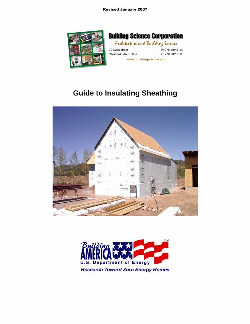
Guide to Insulating Sheathing
Table of Contents
Introduction 3 Background 4 Material Properties6
Types of Foam6 Thermoplastics6 Thermosets 6
R-value 7 Permeance 7 Durability8
Technical Concepts 9 Additional Thermal Resistance9 Rain Water Management12 Vapor Management 14 Condensation Resistance15
Design and Construction 20 General Installation20 Cladding Attachment 21 Roof Connection21 Foundations Connection22 Window installation24
Related Concepts28 Advanced Framing 28 Cross Bracing and Inset Shear Panels 29
Introduction
Residential housing design continues to move towards the development of high performance sustainable building systems To be sustainable a building must not only be efficient and durable but also economically viable From this new methods of enclosure design have been examined that provide high thermal performance and long-term durability but also take opportunities to reduce material use (including waste) simplify or integrate systems and details and potentially reduce overall initial costs of construction
One concept relating to enclosure design is to incorporate the use exterior foam insulating sheathing into the construction of the wall assembly As with any building enclosure system appropriate detailing for the management of water vapor and energy transfer are necessary
Guide to Insulating Sheathing Building Science Corporation Page 3 of 30
Background
As the desire to provide more thermally efficient enclosure assemblies increased so did the problems with moisture accumulation within building enclosure assemblies Often the problems occurred due to new materials being introduced into the designs for specific purposes without adequate understanding of all of their properties and the potential impacts on the assembly as a whole Many enclosure failures occurred due to the lack of appreciation that products and materials have other properties than the ones that they are initially designed for
copy buildingscience
com
copy buildingscience
com
copy buildingsci
enceco
m
Though these lessons were hard learned we can now use this knowledge for our benefit Through examining and understanding materials based on all of their properties (not just what they were initially created for) we can eliminate redundancies in enclosure design making the systems simpler and more cost effective
In cold climates the use of exterior rigid insulation sheathing boards has been a method of increasing thermal performance of the enclosure as well as a means of reducing the condensation potential within exterior wall assemblies This concept while not new has become more accepted in recent years and is being used in residential construction While this method has proven to be effective it was introduced as an addition to standard residential construction for a specific purpose The base wall assembly generally remained unchanged with other materials used for air sealing and water management
The opportunity that presented itself was the integration of the exterior rigid insulation board into the enclosure assembly to act not only as insulation but also as the primary sheathing and in certain areas as the drainage plane and vapor control layer for the wall assembly This system combined with advanced framing concepts can provide cost savings from the reduction of building materials used (fewer studs the elimination of plywood or OSB sheathing and housewraps) and the reduction of construction waste (incorporating standard construction product dimensions in the design of the building to minimize cutting)
Guide to Insulating Sheathing Building Science Corporation Page 4 of 30
copy buildingscience
com
copy buildingscience
com
copy buildingsci
enceco
m
While the use of exterior insulation was initially used in cold climates the benefits of the integrated system from increased thermal performance and reduced costs make it viable in other climates zones as well
Still proper understanding of the type of enclosure assemblies suitable for the overall climate zone in which the house is being constructed is critical The choice of materials used will vary from climate zone to climate zone and the details for the water resistant barrier become more critical in areas of increased rainfall
This guide examines the application of insulating sheathing to exterior wall assemblies from the technical conceptual design and benefits to the installation and interaction with other building systems
Guide to Insulating Sheathing Building Science Corporation Page 5 of 30
Material Properties
There are three main types of insulating sheathing currently being used in the industry Expanded Polystyrene (EPS) Extruded Polystyrene (XPS) and Polyisocyanurate (Polyiso) Each of these products all has a different set of physical properties that will affect the dynamic of the wall assemblies in regards to the transmission and management of heat and moisture
Types of Foam
Insulating foam sheathings are split into two basic categories 1) thermoplastics 2) thermosets Both EPS and XPS foams are thermoplastic foams while Polyisocyanurate is a thermoset foam
Thermoplastics
Thermoplastics are based on linear or slightly branched (non-cross linked) polymers These foams have a definite melting range and will soften and melt at elevated temperatures They are also more prone to react and degrade when in contact with some organic solvents as found in some paints adhesives and fuels Therefore it is important to only use manufacturer approved compatible materials when using thermoplastic foams
Of the thermoplastic foams EPS and XPS are the most common used in the industry Both products are based on polystyrene resin and are considered to be closed cell1 rigid foams
The manufacturing of EPS involves the expanding of polystyrene beads to fill a mold The densities of EPS foam can be varied if desired Increased density results in increased thermal resistance and compressive strength The density of the product also affects the vapor transmission While EPS is a closed cell foam (slow water vapor and air transmission through the cell walls) the gaps between the cells will still allow for moisture to pass through the matrix With increased density these spaces are reduced and the ability of the foam to allow water transmission is reduced
XPS foams are formed by mixing molten polystyrene with a blowing agent at the correct time at an elevated temperature and at an elevated pressure and then extruding the foam through a die to the atmosphere This creates a more regular cell structure providing for better strength properties and higher water resistance that EPS foams The density of XPS foams can also be varied allowing for increased compressive strength however due to the more regular cell structure this has little to no effect on the vapor transmission properties
Thermosets
Thermoset plastics are based on cross linked polymers This will allow thermoset plastics to be used for higher temperature applications as they do not usually exhibit a melting range and will instead char and burn Thermoset foams are also generally more resistant to solvents and chemicals
The most common thermoset foam on the market is polyisocyanurate While traditional polyurethane foams were created by reacting isocyanate with polyol (and other blowing agents catalysts and surfactants) polyisocyanurate foams can theoretically be created with no polyol using only isocyanate reacting with itself (and other blowing agents catalysts and surfactants) In general though commercial polyisocyanurate foam used in the market is really polyurethane foam modified with polyisocyanurate or a ldquoblendrdquo of the two foams The use of the blend increases the fire resistance while maintaining the thermal resistance and strength of the material
1 Closed cell foams as apposed to open cell foams have a higher resistance to air and vapor flow due to the cell walls being continuous
Guide to Insulating Sheathing Building Science Corporation Page 6 of 30
R-value
The thermal resistance of each of the products will vary In general EPS foam has the lowest R-value per inch with XPS being slightly more efficient and with Polyisocyanurate having the best R-value per inch The R-value of EPS foams can be increased by increasing the density of the product however the more dense expanded foams are less common in the market Typically EPS foam has a rated value of approximately R-4 per inch XPS foams are pretty consistent with an R-value of approximately R-5 per inch
While the thermal resistance of these thermoplastic foams is generally stable over the long term and therefore the initial R-value at the time of manufacturing will not change over time polyisocyanurate foams are rated with a Long Term Thermal Resistance (LTTR) R-value representing a 15 year weighted R-value This is in response to issues of thermal drift of the polyisocyanurate products Thermal drift occurs due to the gasses produced during the forming of the foam These gasses slowly diffuse out of the product over time and are replaced by air Since these gasses also have more thermal resistance than air the R-value of polyisocyanurate diminishes over time as the gasses diffuse out of the product Facings on the insulation board such as aluminum foil will slow this process down as the diffusion can only occur out the edges of the product and not through the front and back faces Most polyisocyanurate products have an LTTR R-value of R-65 per inch
Permeance
The permeance of the materials is important when examining the vapor control strategy of the wall assembly Materials can be separated into four general classes based on their permeance
Vapor impermeable 01 perms or less (Class I vapor retarder ndash considered a vapor barrier)
Vapor semi-impermeable 10 perms or less and greater than 01 perm (Class II vapor retarder)
Vapor semi-permeable 10 perms or less and greater than 10 perm (Class III vapor retarder)
Vapor permeable greater than 10 perms (Not considered a vapor retarder)
For unfaced insulation the permeability is a function of the material thickness In general most product manufacturers list the permeance of the material based on a thickness of 1 inch Increasing or decreasing the thickness of the material will affect the permeance This can become an issue when using XPS foam insulation 1 inch of XPS has a permeance of 11 perms (borderline Class II and Class III vapor retarder) increasing the thickness to 2 inches decreases the permeance to 055 perms (middle of the Class II vapor retarder) Therefore 1 inch of XPS is considered to be vapor semi-permeable while 2 inches is considered to be vapor semi-impermeable
For faced rigid insulation boards (such as foil faced or glass fiber faced polyisocyanurate) the permeance of the facing is often much lower than the permeance of the polyisocyanurate and will govern the overall permeability of the sheathing board For these products the permeance will not change with increasing thickness
Guide to Insulating Sheathing Building Science Corporation Page 7 of 30
Table 1 Material Properties
Expanded Polystyrene (EPS) R-valueinch 75F
(Fft2hBtu) Density
(pcf) Permeance
(perms) Water Absorption
( by volume) Compressive Strength
(psi) 32 075 500 40 5 39 100 500 40 10 42 150 350 30 15 44 200 200 20 25
Extruded Polystyrene (XPS) 46 120 110 03 15 50 130 110 03 15 50 160 110 03 25 50 220 110 03 60
Polyisocyanurate unfaced 60 160 277 - 449 - -foil faced 65 20 003 10 25 glass fiber faced 65 200 lt10 10 25
Durability
Insulating sheathings are generally fairly durable materials however they are not completely resistant to degradation Polystyrene boards will degrade if left exposed to UV radiation for prolonged periods of time The boards will discolor and a thin dusty film will form on the boards Faced Polyisocyanurate is more resistant to UV degradation however the unfaced polyisocyanurate boards are also susceptible to UV degradation
EPS boards are less durable for excessive handling The edges of the boards can break off as the bond between the expanded beads is not as strong as the matrix formed with XPS and polyisocyanurate This can leave the boards with more rounded edges and decrease the thermal value at the joints between the boards Careful cutting and handling is recommended when using EPS boards
Most insulating sheathing boards are resistant to moisture however problems with warping and cupping of the foil faced polyisocyanurate have occurred in the past when the boards have been left exposed to the weather for extended periods of time
As a general rule it is considered good practice to store the boards in a protected covered and dry location on site and to limit the amount of time the boards are left exposed before being covered over by the cladding material
Guide to Insulating Sheathing Building Science Corporation Page 8 of 30
Technical Concepts
Additional Thermal Resistance
With rising utility cost designing homes to be more energy efficient is increasing in importance Part of the overall efficiency of a house is the thermal resistance of the various enclosure assemblies Common residential construction use wall framing based on either 2x4 or 2x6 dimensional lumber with insulation installed in the stud cavities created by the framing members With cavity insulation the overall thermal resistance can be varied somewhat by using different types of insulation varying the installation methods and varying the stud spacing but there is still a limit because of the depth of the stud cavity Adding insulating sheathing to the exterior of the assembly is a simple method of increasing the overall thermal resistance of the wall assembly beyond that possible with cavity insulations and thereby increasing the overall efficiency of the house
When examining the overall thermal resistance of the wall assembly the effective R-value must be considered A simple method than can be used to estimate the effective R-value of the cavity space is through using the isothermal planes method set out in Chapter 25 of the ASHRAE Fundamentals 2005 While this method is not as accurate as some other more sophisticated computer simulation models it is a means to get a rough idea of the effective insulating value of an assembly With the isothermal method the effective R-value of the cavity assembly is a proportional sum of the various U-values of the different components based on material fractions
U(cavity) = U(studs)middotF(studs) + U(insulation)middotF(insulation)
Where U(cavity) = average U value of the insulation and studs U(studs) = U value of wood framing U(insulation) = U value of cavity insulation F(studs) = fraction of area of studs headers and sill plates F(insulation) = fraction of area of insulation
Therefore the effective R-value of the cavity can be expressed as
R(cavity) = 1U(cavity)
The overall R-value of the assembly is a sum of the thermal resistance of all of the components
R(total) = R(comp 1) + R(comp 2) + hellip + R(comp n)
Where R(total) = total R-value of the assembly R(comp) = individual effective R-value of each material layer
As an example the effective cavity insulation value and the total effective R-value for various assemblies were calculated The fiberglass batt or blown cellulose may be rated as R-19 however due to the wood studs and other framing members the effective thermal resistance may be as much as 35 less than the rated cavity insulation leaving an effective value of only R-125 for the cavity as seen in the calculations below
Guide to Insulating Sheathing Building Science Corporation Page 9 of 30
Element
Cavity section R-value
Stud section R-value
Outside Air Film 017 017 12 Plywood 062 062 2x6 Wood Stud na 583 55 Fiberglass Batt 19 na 12 Interior Gypsum 045 045 Interior Air Film 068 068 Total 2092 775
The effective R-value of the following assembly with a 23 framing fraction is
R(cavity) = 1[(07719)+(023583)] R(cavity) = 125
R(total) = 017+062+125+045+068 R(total) = 1442
Insulating sheathing provides additional insulation to the house that is run continuous past the exterior face of the wood studs Because of this the rated R-value for the insulating sheathing is very close to the effective R-value of the insulating sheathing in the assembly With the lack of framing penetrating through the layer insulating sheathing the whole R-value can be generally be used This allows for large increases in the effective R-value of the assembly without substantially increasing the thickness of the wall
Incorporating 1 inch of rigid insulation into the design of the previous example wall assembly yields the following effective R-value for the assembly
R(cavity) = 1[(07719)+(023583)] R(cavity) = 125
R(total) = 017+5+062+125+045+068 R(total) = 1942
Element
Cavity section R-value
Stud section R-value
Outside Air Film 017 017 1 Rigid Insulation 5 5 12 Plywood 062 062 2x6 Wood Stud na 583 55 Fiberglass Batt 19 na 12 Interior Gypsum 045 045 Interior Air Film 068 068 Total 2592 1275
Adding one inch of insulating sheathing (R-5 for this example) will increase a 2x6 stud wall from an effective R-144 to an effective R-194 This represents an increase of 35 effective thermal resistance with only 15 increase in the overall wall thickness
Guide to Insulating Sheathing Building Science Corporation Page 10 of 30
Element Cavity Stud
Outside Air Film 017 017 1 Rigid Insulation 5 5 2x6 Wood Stud na 583 55 Fiberglass Batt 19 na 12 Interior Gypsum 045 045 Interior Air Film 068 068 Total 253 1213
If the insulating sheathing is used as the primary sheathing (eliminating the plywood or OSB from the exterior)
R(cavity) = 1[(07719)+(023583)] R(cavity) = 125
R(total) = 017+5+125+045+068 R(total) = 1880
With this configuration the wall thickness is only increased by 8 while the effective thermal resistance increases from R-144 to R-188 a 31 increase
Element
Cavity section R-value
Stud section R-value
Outside Air Film 017 017 2 Rigid Insulation 10 10 2x6 Wood Stud na 583 55 Fiberglass Batt 19 na 12 Interior Gypsum 045 045 Interior Air Film 068 068 Total 303 1713
Incorporating 2 inches of rigid insulation into the design of the example wall assembly yields the following effective R-value for the assembly
R(cavity) = 1[(07719)+(023583)] R(cavity) = 125
R(total) = 017+10+125+045+068 R(total) = 2380
Adding two inches of rigid insulation to the exterior (R-10) will increase the effective R-value from R-144 to R-238 This represents an increase of 65 over the original effective R-value
copy buildingsciencecom
Guide to Insulating Sheathing Building Science Corporation Page 11 of 30
Rain Water Management
For most climate zones the management of exterior rain water is the most critical aspect of the moisture management system of the building enclosure The fundamental principle of water management is to drain the water downwards and outwards out of the building and away from the building In order for the building and building assemblies to drain properly detailing of the drainage plane must be carefully designed
There are several options for creating a drainage plane in the wall assembly The choice of which method to use is based on weighing the risks involved
Water Resistance
As the water penetration resistance of the assembly increases the risk of moisture problems decreases
Moisture Tolerance of Assembly
As the moisture tolerance of the materials that comprise the assembly increases (masonry and concrete vs wood and steel) the risk of moisture related problems decreases
Exposure
As the exposure to rainfall increases the risk of moisture related problems increases
Rainfall
As the amount of rainfall increases the risk of moisture related problems increases
Drying Potential
As the ability of an assembly to dry increases due to the climate design or both the risk of moisture related problems decreases
Workmanship
As the craftsmanship of the construction of the assemblies and their connection details increases the risk of moisture related problems decreases
Guide to Insulating Sheathing Building Science Corporation Page 12 of 30
There are four strategies proposed for maintaining the continuity of the drainage plane with the incorporation of insulating sheathing to the exterior
Wall Section 1 - Insulating Sheathing and Housewrap over Plywood or OSB The first strategy involves installing the insulating sheathing over top of a layer of building paper or housewrap and wood sheathing This is the most durable assembly proposed in this guide as the drainage plane material (building paper or house wrap) is supported by the plywood sheathing and protected against wind loading and other environmental factors by the insulating sheathing This type of assembly would be recommended in areas or high exposure and rainfall
copy buildingsciencecom
copy buildingsciencecom
copy buildingsciencecom
copy buildingsciencecom
Wall Section 2 - Insulation Sheathing and Housewrap over Wood Studs The next proposed strategy is to install the insulating sheathing overtop of a housewrap that is stretched over wood studs In this configuration the housewrap drainage plane is protected from exterior elements (excessive wind loading and rain exposure) The type of assembly would work effectively in most rainfall zones though potentially not in high exposure locations With the lack of wood sheathing support on the exterior of the framing more care is required during the installation of the housewrap and insulating sheathing
Wall Section 3 - Housewrap installed over Insulating Sheathing and Wood Studs The third strategy would be to install the housewrap to the exterior of the insulating sheathing essentially replacing the plywood or OSB in a traditional wall assembly with insulating sheathing The housewrap is more exposed to exterior elements such as wind loading and moisture and may not be as durable as the other approaches In addition the fasteners used to install the housewrap must be able to penetrate all the way through the insulating sheathing and into the wood studs beyond This wall approach would function adequately in most rainfall zones
Wall Section 4 - Insulating Sheathing as the Drainage Plane The final approach would be to use the insulating sheathing as the primary sheathing and drainage plane of the assembly In order to achieve this all the vertical joints must be taped or sealed and special flashing details must be used With some question as to the long term dimensional stability of insulating sheathing products this approach is considered to be in the higher risk category and should only be used in areas with limited rainfall and exposure where rain water management is not as critical
Guide to Insulating Sheathing Building Science Corporation Page 13 of 30
Vapor Management
The design of the vapor management system should attempt to allow maximum drying of the wall assembly from diffusion while limiting the amount of moisture able to be driven into the assembly Where possible drying to both sides of the construction assembly is encourage however in some circumstances more stringent vapor control is required As a general rule for standard framed construction the vapor retarding layer should be placed to the interior of the assembly in cold climates (reducing the water vapor from the higher humidity interior air from diffusing into the assembly) while in hot humid climates the vapor retarding layer should be placed to the exterior of the assembly (reducing the water vapor from the hot humid outside air from diffusing into the assembly) copy buildingsciencecom
copy buildingsciencecom
copy buildingsciencecom
copy buildingsciencecom
Therefore in a general sense for cold climates it is preferable to use a more vapor permeable insulating sheathing (such as EPS and unfaced XPS) on the exterior and in hot humid climates it is preferable to use a more vapor impermeable sheathing on the exterior of the assembly (such as foil faced polyisocyanurate and plastic film faced XPS)
For mixed humid climates the system choices become more difficult as the assembly needs to be protected from wetting from both the interior as well as the exterior The drying can be predominantly to the exterior the interior or in both directions in a flow through type assembly Often these strategies need to be combined with other vapor management strategies such as building pressurization (or depressurization) and supplemental dehumidification There is also a strategy to place the vapor control layer towards the middle of the assembly This approach will be discussed in the next section on Condensation Resistance
There are also some exceptions With absorptive claddings such as brick veneer and stucco a high inward vapor drive can occur due to solar radiation heating up the wet cladding and creating a high vapor pressure difference between the brick (or stucco) and the exterior and the brick (or stucco) and the interior This vapor pressure differential will cause moisture to be driven into the assembly if there is not adequate vapor control on the exterior For this reason insulating sheathing that is installed behind a masonry veneer or stucco should be vapor semi-impermeable or it can be semi-permeable if combined with an impermeable or semi-impermeable membrane
Guide to Insulating Sheathing Building Science Corporation Page 14 of 30
copy buildingsciencecom
copy buildingsciencecom
copy buildingsciencecom
copy buildingsciencecom
Condensation Resistance
Condensation can occur when moisture laden air comes in contact with a material with a surface temperature below the dewpoint temperature of the air In a cold climate wall assembly this usually occurs at the interior face (or back side) of the exterior sheathing when moisture from the conditioned space penetrates into the wall assembly through vapor diffusion or air movement The addition of insulating sheathing to the exterior of an assembly in colder climates can provide for some condensation resistance within the wall assembly as it will change the thermal gradient through the assembly
The thermal gradient across an assembly describes how the temperature varies from one side of an assembly through to the other The thermal gradient can be predicted by examining the individual proportion of thermal resistance provided by each component Each different component will provide a percentage of the total thermal resistance of the assembly Therefore the change in temperature of any component is based on the percentage of thermal resistance provided by that component multiplied by the overall temperature difference across the assembly
∆T(comp) = R(comp) R(total) x (T(in) ndash T(out))
Where ∆T(comp) = temperature change across a component R(comp) = thermal resistance of the component R(total) = total thermal resistance of the assembly T(in) = interior temperature T(out) = exterior temperature
To determine the temperature at any given surface in the assembly the individual temperature changes across each component in the assembly up to the desired surface is added to the exterior temperature
T(surface) = T(out) + ∆T(comp 1) + ∆T(comp 2) + hellip + ∆T(comp n)
The example below examines the temperature of the inside surface of the exterior sheathing with an exterior temperature of 32F and an interior temperature of 70F For the first section below the temperature at the inside surface of the exterior sheathing would be calculated as
T(surface) = T(out) + ∆T(exterior air film) + ∆T(plywood)
T(surface) = 32 + [0172092 x (68-32)] + [0622092 x (68-32)] T(surface) = 32 + [00081 x 38] + [00296 x 38] T(surface) = 32 + 031 + 113 T(surface) = 3344 F
Guide to Insulating Sheathing Building Science Corporation Page 15 of 30
For the next two sections the temperature of the inside surface of the exterior sheathing is 3977 F and 4474 F respectively
copy buildingsciencecom
copy buildingsciencecom
copy buildingsciencecom
copy buildingsciencecom
As it can be seen from the figure above with the additional thermal resistance of the rigid board insulation material the temperature of the inside face of the sheathing will be warmer in the winter months than with traditional wood sheathing alone Since the surface temperature is warmer there is less of a risk of condensation forming on the inside face If the exterior wood sheathing eliminated the system becomes even more durable as insulation sheathings are resistant to water and will not degrade if a small amount of condensation does occur
For this to be applied effectively understanding the climate zone and the interior environmental conditions in which the assembly is being designed is very important As an example three different wall sections were examined in three different locations In each example the interior conditions were set at 70F and 35 Relative Humidity Air under these conditions will have a dew point of approximately 40F (determined from the psychometric chart) Also each assembly was assumed to have a vapor permeable interior finish or no effective interior air barrier layer allowing for the more humid interior air to come in contact with the interior face (condensing layer) of the exterior sheathing
The three wall sections were analyzed for the Chicago IL area with the exterior conditions based on the average monthly temperatures for a one year cycle The first wall section designed under the traditional approach with wood sheathing is at risk of condensation accumulation on the back of the wood sheathing from the middle of November to the middle of March (this is shown by the segment of the temperature profile that drops below the dewpoint of 40F for the interior air) With the addition of 1 inch of insulating sheathing the time period of condensation potential time is now from the middle of December to the middle of February The addition of 2 inches of insulating sheathing the temperature profile does not drop below the dewpoint temperature and therefore no longer at risk With 2 inches of insulating sheathing the wall assembly would not require an interior vapor control layer or interior continuous air seal
Guide to Insulating Sheathing Building Science Corporation Page 16 of 30
copy buildingsciencecom
copy buildingsciencecom
copy buildingsciencecom
copy buildingsciencecom
0
10
20
30
40
50
60
70
80
July
Augu
st
Septem
ber
Octo
ber
Novem
ber
Decem
ber
Janu
ary
Februa
ry
March
April
May
June
Ju
ly
Interior
Exterior
Condensing Surface Wall 1
Condensing Surface Wall 2
Condensing Surface Wall 3
Dew Point at 70F and 35RH
If the wall sections are moved to Minneapolis MN exterior insulating is no longer adequate on itrsquos own to manage the condensation resistance of the wall assembly For each profile an interior vapor control layer and air barrier would be required
0
10
20
30
40
50
60
70
80
July
Augu
st
Septem
ber
Octo
ber
Novem
ber
Decem
ber
Janu
ary
Februa
ry
March
April
May
June
Ju
ly
Interior
Exterior
Condensing Surface Wall 1
Condensing Surface Wall 2
Condensing Surface Wall 3
Dew Point at 70F and 35RH
Conversely if the profiles are moved to Seattle WA the exterior conditions are not cold enough to create problems with condensation even with the traditional approach (as long as the interior relative humidity is maintained below 35 RH)
Guide to Insulating Sheathing Building Science Corporation Page 17 of 30
copy buildingsciencecom
copy buildingsciencecom
copy buildingsciencecom
copy buildingsciencecom
0
10
20
30
40
50
60
70
80
July
Augu
st
Septem
ber
Octo
ber
Novem
ber
Decem
ber
Janu
ary
Februa
ry
March
April
May
June
Ju
ly
Interior
Exterior
Condensing Surface Wall 1
Condensing Surface Wall 2
Condensing Surface Wall 3
Dew Point at 70F and 35 RH
If the interior conditions change the condensation potential will also change Reexamining the Chicago IL sections once again and varying the interior relative humidity demonstrates that 1 inch of insulating sheathing would be adequate if the relative humidity was kept below 25 (dewpoint of 32F ) or that 2 inches of insulating sheathing would not be adequate if the interior relative humidity increases to 50 (dewpoint of 50F)
0 10
20 30 40
50 60
70 80
July
Augu
st
Septem
ber
Octo
ber
Novem
ber
Decem
ber
Janu
ary
Februa
ry
March
April
May
June
Ju
ly
Interior
Exterior
Condensing Surface Wall 1
Condensing Surface Wall 2
Condensing Surface Wall 3
Dew Point at 70F and 35 RH
Dew Point at 70F and 25 RH
Dew Point at 70F and 50 RH
While the use of insulating sheathing can help to reduce the condensation potential it is only a component in the overall design of the building enclosure assembly The examples above were used to demonstrate how insulating sheathing can reduce the condensation potential in an assembly however design of the building enclosure will likely include other water air and vapor management strategies as well
As mentioned earlier in mixed humid climates the thermal gradient approach can be used as part of the vapor management strategy The use of impermeable insulating sheathing materials of adequate thickness to ensure that the dewpoint temperature is not reached within the assembly will allow for the interior vapor control layer to be eliminated from the assembly (installing a vapor retarder on the interior would actually be detrimental to the system) With the impermeable or semi-impermeable nature of the
Guide to Insulating Sheathing Building Science Corporation Page 18 of 30
sheathing the exterior face of the board would function as a vapor retarder during the cooling month while the interior face of the insulating sheathing would function as a vapor retarder in the heating months The air barrier for the system could also be installed to the interior or exterior of the assembly This approach should also be combined with a slight positive interior pressure to limit the amount of infiltration of moist air during the cooling season as well as some interior moisture control to ensure that the interior RH does not exceed the maximum levels to prevent condensation on the interior surface of the exterior sheathing during the heating season
copy buildingsciencecom
copy buildingsciencecom
copy buildingsciencecom
copy buildingsciencecom
Guide to Insulating Sheathing Building Science Corporation Page 19 of 30
Design and Construction
The following four wall sections are used as the basis for discussion for this section
copy buildingsciencecom
copy buildingsciencecom
copy buildingsciencecom
copy buildingsciencecom
General Installation
Insulating sheathing should be installed based on manufacturerrsquos recommendations for fastener type and amount It is recommended to layout the insulating sheathing such that vertical joints do not occur at the corners of window and door openings or over window heads if possible
In Wall Section 1 and Wall Section 2 the primary drainage plane occurs behind the insulating sheathing All water management details (flashing and window installation details) should be tied back to the plane of the housewrap In these configurations while the insulating sheathing is not officially considered to be part of the drainage system of the wall it will provide some protection for the housewrap in preventing much of the exterior rain water that penetrates past the cladding from penetrating through to the actual drainage plane
For Wall Section 3 the primary drainage plane to the exterior of the insulating sheathing and more exposed to the elements In this configuration the water management and window installation details are integrated into the housewrap at the exterior face of the insulating sheathing Water management details would be the same as normal details of recommended good practice for wood sheathed house design
Wall Section 4 requires some special detailing All the joints between the insulation boards must be designed in such a way as to prevent water from penetrating past the exterior face of the insulation Sealing or taping the vertical joints should be done and if possible products that use shingle lapped or tongue and groove joints should be used A polyethylene flashing is recommended to be installed at the horizontal joints in the system
Guide to Insulating Sheathing Building Science Corporation Page 20 of 30
In order for the insulation sheathing to be used as a water resistive barrier the vertical plane of the exterior face of the sheathing must be as continuous as possible This is to prevent locations within the wall assembly where drainage could be blocked or where water might be held
copy buildingsciencecom
copy buildingsciencecom
copy buildingsciencecom
copy buildingsciencecom
For added protecting window head flashing and roof step flashings can be easily regletted into the face of the foam sheathing providing for better protection against flashing failure and reverse flashing problems The reglette should only penetrate into the face of the sheathing and not all the way through the sheathing
Cladding Attachment
For siding systems (wood vinyl and fiber cement) and masonry veneers there is virtually no change from standard recommended practice for cladding attachment details One of the only differences is that all fasteners must be installed through to the studs as insulating sheathing does not have adequate structural capacity both in shear and pull out strength
For Wall Section 1 and Wall Section 2 cladding systems such as traditional hard coat stucco (including thin brick and manufactured stone veneer) and acrylic stucco can be directly applied to the insulation board With these types of systems it is recommended to use drained insulation boards (ones with vertical grooves cut in the back) or to use a vertically textured (or profiled) housewrap to ensure that there is a drainage space behind the rigid board
For Wall Section 3 and Wall Section 4 traditional hard coat stucco (including thin brick and manufactured stone veneer) should NOT be installed without the addition of at least one layer of building paper or house wrap between the stucco renderings and the housewrap or drainage plane sheathing to act as a bond break
Roof Connection
Popular roof construction types will vary from one region to another Much of the country relies on sloped roof assemblies with eave overhangs In other areas flat roof construction is more common The roof wall connection will vary therefore depending on the type of roof assembly used
In sloped roof applications the insulating sheathing is installed up to the underside of the roof truss If desired the insulating sheathing can be notched around the roof trusses to act as a wind shield for the attic insulation
For Wall Section 1 and Wall Section 2 at gable ends and parapets the insulating sheathing is not required to extend to the full height of the construction since the drainage plane is maintained behind the insulation through the use of a housewrap Due to this the insulating sheathing can be stopped at the top of the plane of attic insulation However it may be convenient to extend the insulating sheathing the full height to simplify the cladding attachment at these areas Otherwise alternative methods to fur out and support the cladding will be required
Conversely For Wall Section 3 and Wall Section 4 the continuity of the drainage plane must be maintained to the exterior of the insulating sheathing For these wall sections often the simplest way to maintain the continuity of the drainage plane is to install the insulating sheathing up to the top of the parapet or over the gable end An alternative method for maintaining the drainage plane is to use a thin profile structural sheathing furred out and installed so that it is in plane or proud of the insulating sheathing to maintain the continuity of the drainage plane
Guide to Insulating Sheathing Building Science Corporation Page 21 of 30
copy buildingsciencecom
copy buildingsciencecom
copy buildingsciencecom
copy buildingsciencecom
Foundations Connection
The installation details for insulating sheathing at foundations are generally the same for all foundation types The intention is to continue the sheathing past the top edge of the foundation or basement wall to create a shingle lap with the foundation For walls with brick veneer this may not be possible In this situation a seat should be cast into the top of the foundation wall so that the brick and the insulation sheathing terminate at a level below the bottom plate of the stud wall This will allow a shingle lap joint to be created
Guide to Insulating Sheathing Building Science Corporation Page 22 of 30
copy buildingsciencecom
copy buildingsciencecom
copy buildingsciencecom
copy buildingsciencecom
Guide to Insulating Sheathing Building Science Corporation Page 23 of 30
Window installation
The following window installation sequence details is applicable to Wall Section 1 (Wall Section 2 details would be almost identical ndash with the elimination of wood sheathing behind the housewrap)
copy buildingsciencecom
copy buildingsciencecom
copy buildingsciencecom
copy buildingsciencecom
1 Wood frame wall with OSB and housewrap 2 Modified ldquoIrdquo cut in housewrap 3 Housewrap folded in at jambs and sill Housewrap at head temporarily folded up or alternatively
tucked under Install backdam
4 Install adhesive backed sill flashing and corner flashing patches at sill 5 Apply sealant at jambs head and sill Alternatively sealant can be applied to the back side of the
nailing flange (sealants housewraps and flashings must be chemically compatible) 6 Install window plumb level and square as per manufacturerrsquos instructions
Guide to Insulating Sheathing Building Science Corporation Page 24 of 30
copy buildingsciencecom
copy buildingsciencecom
copy buildingsciencecom
copy buildingsciencecom
7 Install jamb flashing first Install a drip cap (if applicable) Install head flashing 8 Fold down head housewrap 9 Apply corner patches at head Air seal window around the entire perimeter on the interior with
sealant or non-expanding foam Install foam sheathing over housewrap
Guide to Insulating Sheathing Building Science Corporation Page 25 of 30
The following window installation sequence details are applicable to Wall Section 4 (Wall Section 3 details would be almost identical ndash addition of housewrap to the exterior of the insulating sheathing prior to window rough opening preparation)
copy buildingsciencecom
copy buildingsciencecom
copy buildingsciencecom
copy buildingsciencecom
1 Install foam sheathing on wood frame wall 2 Install backdam 3 Install first piece of adhesive backed sill flashing apply second piece of adhesive backed sill
flashing
4 Install corner flashing patches at sill 5 Install adhesive backed jamb flashings (jamb flashing adhered to foam and stapled to frame) 6 Apply sealant at jambs head and sill Alternatively sealant can be applied to the back side of the
nailing flange (sealants housewraps and flashings must be chemically compatible)
Guide to Insulating Sheathing Building Science Corporation Page 26 of 30
copy buildingsciencecom
copy buildingsciencecom
copy buildingsciencecom
copy buildingsciencecom
7 Install window plumb level and square as per manufacturerrsquos instructions 8 Install jamb flashing 9 Install drip cap (if applicable) install head flashing tape head flashing air seal around the
perimeter on the interior with sealant or low expanding foam
Guide to Insulating Sheathing Building Science Corporation Page 27 of 30
copy buildingsciencecom
copy buildingsciencecom
copy buildingsciencecom
copy buildingsciencecom
Related Concepts
Advanced Framing
The use of advanced framing with insulation sheathing is another concept used to reduce the amount of materials in residential construction The layout of the sheathing boards over the area of the wall framing should be done to minimize the amount of cutting of the material and construction waste created
wall
Single top plate
studs by rim
Single
rough
support will be required under point
solid blocking
Two stud corners
No headers in non-bearing
stud at
opening
No cripples under window opening
Header hangers instead of jack studs (see Figure 55)
Roof framingtrusses line up with wall
and floor framing
Insulated header
Single top plate
Point load transferred between
closure material acting as header If rim closure material is non-structural
loads Use
between joists
This will impact the effective thermal resistance of the wall assembly as well Standard residential construction will end up with a framing fraction for the wall assemblies of around 23 of the wall area With advanced framing this fraction can be reduced down to approximately 16 and sometimes even less If we reexamine the techniques for calculating the effective R-value of the assembly as used in the Thermal Resistance section we obtain the following results
Guide to Insulating Sheathing Building Science Corporation Page 28 of 30
copy buildingsciencecom
copy buildingsciencecom
copy buildingsciencecom
copy buildingsciencecom
Element
Cavity Section R-value
Stud Section R-value
Outside Air Film 017 017 1 Rigid Insulation 5 5 2x6 Wood Stud na 583 55 Fiberglass Batt 19 na 12 Interior Gypsum 045 045 Interior Air Film 068 068 Total 253 1213
The effective R-value of the following assembly with a 16 framing fraction is
R(cavity) = 1[(08419)+(016583)] R(cavity) = 1396
R(total) = 017+062+1396+045+068 R(total) = 2026
The same effective R-value with a 23 framing fraction yielded a total R-value of 1880 This represents a 78 increase in thermal resistance for the entire assembly
Cross Bracing and Inset Shear Panels
In Wall Sections 2 3 and 4 the regular method for shear resistance has been removed from the assembly (traditionally wood sheathing over the exterior of the building) Due to this alternative methods for providing shear resistance must be incorporated into the design
A common approach is to install exterior structural wood sheathing at the corners and at regular intervals as needed to provide for the lateral load resistance requirements for the location (wind and seismic) Installing the structural wood sheathing to exterior interferes with the installation of the insulating sheathing This can create problems with drainage plane continuity and thermal bridging (due to the reduction in insulation thickness)
The recommendation is to use systems and techniques that can be installed flush with the exterior face of the wood studs This way the insulation can be installed in a continuous uniform thickness over the entire exterior wall area Some of the methods to achieve this are through the use of metal cross bracing or inset shear panels
Guide to Insulating Sheathing Building Science Corporation Page 29 of 30
With metal cross bracing the thickness of the metal braces are insignificant and do not interfere with the installation of the insulating sheathing The capacity of the metal cross bracing however may not be adequate for areas with high wind loads andor seismic activity In these locations a more robust form of lateral load resistance may be needed
copy buildingsciencecom
copy buildingsciencecom
copy buildingsciencecom
copy buildingsciencecom
Inset shear panels can provide for high levels of lateral load resistance and can be used in all wind and seismic zones Inset shear panels are wood framed panels that fit within the stud spacing of the wall assembly In this way the exterior face of the panel is flush with the exterior face of the wood studs
Depending on the area of the country different requirements for wind and seismic resistance are required The method chosen will depend on the individual code requirements for the area
Guide to Insulating Sheathing Building Science Corporation Page 30 of 30
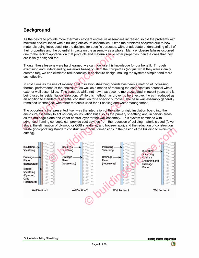
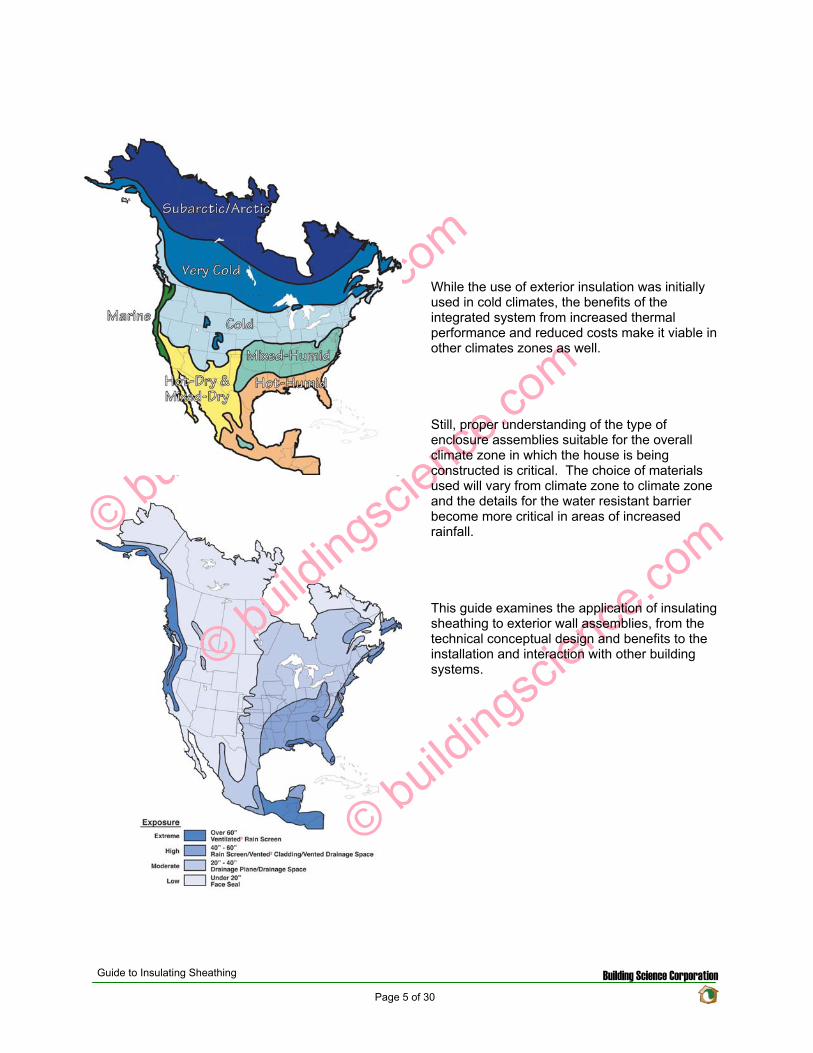
copy buildingscience
com
copy buildingscience
com
copy buildingsci
enceco
m
While the use of exterior insulation was initially used in cold climates the benefits of the integrated system from increased thermal performance and reduced costs make it viable in other climates zones as well
Still proper understanding of the type of enclosure assemblies suitable for the overall climate zone in which the house is being constructed is critical The choice of materials used will vary from climate zone to climate zone and the details for the water resistant barrier become more critical in areas of increased rainfall
This guide examines the application of insulating sheathing to exterior wall assemblies from the technical conceptual design and benefits to the installation and interaction with other building systems
Guide to Insulating Sheathing Building Science Corporation Page 5 of 30
Material Properties
There are three main types of insulating sheathing currently being used in the industry Expanded Polystyrene (EPS) Extruded Polystyrene (XPS) and Polyisocyanurate (Polyiso) Each of these products all has a different set of physical properties that will affect the dynamic of the wall assemblies in regards to the transmission and management of heat and moisture
Types of Foam
Insulating foam sheathings are split into two basic categories 1) thermoplastics 2) thermosets Both EPS and XPS foams are thermoplastic foams while Polyisocyanurate is a thermoset foam
Thermoplastics
Thermoplastics are based on linear or slightly branched (non-cross linked) polymers These foams have a definite melting range and will soften and melt at elevated temperatures They are also more prone to react and degrade when in contact with some organic solvents as found in some paints adhesives and fuels Therefore it is important to only use manufacturer approved compatible materials when using thermoplastic foams
Of the thermoplastic foams EPS and XPS are the most common used in the industry Both products are based on polystyrene resin and are considered to be closed cell1 rigid foams
The manufacturing of EPS involves the expanding of polystyrene beads to fill a mold The densities of EPS foam can be varied if desired Increased density results in increased thermal resistance and compressive strength The density of the product also affects the vapor transmission While EPS is a closed cell foam (slow water vapor and air transmission through the cell walls) the gaps between the cells will still allow for moisture to pass through the matrix With increased density these spaces are reduced and the ability of the foam to allow water transmission is reduced
XPS foams are formed by mixing molten polystyrene with a blowing agent at the correct time at an elevated temperature and at an elevated pressure and then extruding the foam through a die to the atmosphere This creates a more regular cell structure providing for better strength properties and higher water resistance that EPS foams The density of XPS foams can also be varied allowing for increased compressive strength however due to the more regular cell structure this has little to no effect on the vapor transmission properties
Thermosets
Thermoset plastics are based on cross linked polymers This will allow thermoset plastics to be used for higher temperature applications as they do not usually exhibit a melting range and will instead char and burn Thermoset foams are also generally more resistant to solvents and chemicals
The most common thermoset foam on the market is polyisocyanurate While traditional polyurethane foams were created by reacting isocyanate with polyol (and other blowing agents catalysts and surfactants) polyisocyanurate foams can theoretically be created with no polyol using only isocyanate reacting with itself (and other blowing agents catalysts and surfactants) In general though commercial polyisocyanurate foam used in the market is really polyurethane foam modified with polyisocyanurate or a ldquoblendrdquo of the two foams The use of the blend increases the fire resistance while maintaining the thermal resistance and strength of the material
1 Closed cell foams as apposed to open cell foams have a higher resistance to air and vapor flow due to the cell walls being continuous
Guide to Insulating Sheathing Building Science Corporation Page 6 of 30
R-value
The thermal resistance of each of the products will vary In general EPS foam has the lowest R-value per inch with XPS being slightly more efficient and with Polyisocyanurate having the best R-value per inch The R-value of EPS foams can be increased by increasing the density of the product however the more dense expanded foams are less common in the market Typically EPS foam has a rated value of approximately R-4 per inch XPS foams are pretty consistent with an R-value of approximately R-5 per inch
While the thermal resistance of these thermoplastic foams is generally stable over the long term and therefore the initial R-value at the time of manufacturing will not change over time polyisocyanurate foams are rated with a Long Term Thermal Resistance (LTTR) R-value representing a 15 year weighted R-value This is in response to issues of thermal drift of the polyisocyanurate products Thermal drift occurs due to the gasses produced during the forming of the foam These gasses slowly diffuse out of the product over time and are replaced by air Since these gasses also have more thermal resistance than air the R-value of polyisocyanurate diminishes over time as the gasses diffuse out of the product Facings on the insulation board such as aluminum foil will slow this process down as the diffusion can only occur out the edges of the product and not through the front and back faces Most polyisocyanurate products have an LTTR R-value of R-65 per inch
Permeance
The permeance of the materials is important when examining the vapor control strategy of the wall assembly Materials can be separated into four general classes based on their permeance
Vapor impermeable 01 perms or less (Class I vapor retarder ndash considered a vapor barrier)
Vapor semi-impermeable 10 perms or less and greater than 01 perm (Class II vapor retarder)
Vapor semi-permeable 10 perms or less and greater than 10 perm (Class III vapor retarder)
Vapor permeable greater than 10 perms (Not considered a vapor retarder)
For unfaced insulation the permeability is a function of the material thickness In general most product manufacturers list the permeance of the material based on a thickness of 1 inch Increasing or decreasing the thickness of the material will affect the permeance This can become an issue when using XPS foam insulation 1 inch of XPS has a permeance of 11 perms (borderline Class II and Class III vapor retarder) increasing the thickness to 2 inches decreases the permeance to 055 perms (middle of the Class II vapor retarder) Therefore 1 inch of XPS is considered to be vapor semi-permeable while 2 inches is considered to be vapor semi-impermeable
For faced rigid insulation boards (such as foil faced or glass fiber faced polyisocyanurate) the permeance of the facing is often much lower than the permeance of the polyisocyanurate and will govern the overall permeability of the sheathing board For these products the permeance will not change with increasing thickness
Guide to Insulating Sheathing Building Science Corporation Page 7 of 30
Table 1 Material Properties
Expanded Polystyrene (EPS) R-valueinch 75F
(Fft2hBtu) Density
(pcf) Permeance
(perms) Water Absorption
( by volume) Compressive Strength
(psi) 32 075 500 40 5 39 100 500 40 10 42 150 350 30 15 44 200 200 20 25
Extruded Polystyrene (XPS) 46 120 110 03 15 50 130 110 03 15 50 160 110 03 25 50 220 110 03 60
Polyisocyanurate unfaced 60 160 277 - 449 - -foil faced 65 20 003 10 25 glass fiber faced 65 200 lt10 10 25
Durability
Insulating sheathings are generally fairly durable materials however they are not completely resistant to degradation Polystyrene boards will degrade if left exposed to UV radiation for prolonged periods of time The boards will discolor and a thin dusty film will form on the boards Faced Polyisocyanurate is more resistant to UV degradation however the unfaced polyisocyanurate boards are also susceptible to UV degradation
EPS boards are less durable for excessive handling The edges of the boards can break off as the bond between the expanded beads is not as strong as the matrix formed with XPS and polyisocyanurate This can leave the boards with more rounded edges and decrease the thermal value at the joints between the boards Careful cutting and handling is recommended when using EPS boards
Most insulating sheathing boards are resistant to moisture however problems with warping and cupping of the foil faced polyisocyanurate have occurred in the past when the boards have been left exposed to the weather for extended periods of time
As a general rule it is considered good practice to store the boards in a protected covered and dry location on site and to limit the amount of time the boards are left exposed before being covered over by the cladding material
Guide to Insulating Sheathing Building Science Corporation Page 8 of 30
Technical Concepts
Additional Thermal Resistance
With rising utility cost designing homes to be more energy efficient is increasing in importance Part of the overall efficiency of a house is the thermal resistance of the various enclosure assemblies Common residential construction use wall framing based on either 2x4 or 2x6 dimensional lumber with insulation installed in the stud cavities created by the framing members With cavity insulation the overall thermal resistance can be varied somewhat by using different types of insulation varying the installation methods and varying the stud spacing but there is still a limit because of the depth of the stud cavity Adding insulating sheathing to the exterior of the assembly is a simple method of increasing the overall thermal resistance of the wall assembly beyond that possible with cavity insulations and thereby increasing the overall efficiency of the house
When examining the overall thermal resistance of the wall assembly the effective R-value must be considered A simple method than can be used to estimate the effective R-value of the cavity space is through using the isothermal planes method set out in Chapter 25 of the ASHRAE Fundamentals 2005 While this method is not as accurate as some other more sophisticated computer simulation models it is a means to get a rough idea of the effective insulating value of an assembly With the isothermal method the effective R-value of the cavity assembly is a proportional sum of the various U-values of the different components based on material fractions
U(cavity) = U(studs)middotF(studs) + U(insulation)middotF(insulation)
Where U(cavity) = average U value of the insulation and studs U(studs) = U value of wood framing U(insulation) = U value of cavity insulation F(studs) = fraction of area of studs headers and sill plates F(insulation) = fraction of area of insulation
Therefore the effective R-value of the cavity can be expressed as
R(cavity) = 1U(cavity)
The overall R-value of the assembly is a sum of the thermal resistance of all of the components
R(total) = R(comp 1) + R(comp 2) + hellip + R(comp n)
Where R(total) = total R-value of the assembly R(comp) = individual effective R-value of each material layer
As an example the effective cavity insulation value and the total effective R-value for various assemblies were calculated The fiberglass batt or blown cellulose may be rated as R-19 however due to the wood studs and other framing members the effective thermal resistance may be as much as 35 less than the rated cavity insulation leaving an effective value of only R-125 for the cavity as seen in the calculations below
Guide to Insulating Sheathing Building Science Corporation Page 9 of 30
Element
Cavity section R-value
Stud section R-value
Outside Air Film 017 017 12 Plywood 062 062 2x6 Wood Stud na 583 55 Fiberglass Batt 19 na 12 Interior Gypsum 045 045 Interior Air Film 068 068 Total 2092 775
The effective R-value of the following assembly with a 23 framing fraction is
R(cavity) = 1[(07719)+(023583)] R(cavity) = 125
R(total) = 017+062+125+045+068 R(total) = 1442
Insulating sheathing provides additional insulation to the house that is run continuous past the exterior face of the wood studs Because of this the rated R-value for the insulating sheathing is very close to the effective R-value of the insulating sheathing in the assembly With the lack of framing penetrating through the layer insulating sheathing the whole R-value can be generally be used This allows for large increases in the effective R-value of the assembly without substantially increasing the thickness of the wall
Incorporating 1 inch of rigid insulation into the design of the previous example wall assembly yields the following effective R-value for the assembly
R(cavity) = 1[(07719)+(023583)] R(cavity) = 125
R(total) = 017+5+062+125+045+068 R(total) = 1942
Element
Cavity section R-value
Stud section R-value
Outside Air Film 017 017 1 Rigid Insulation 5 5 12 Plywood 062 062 2x6 Wood Stud na 583 55 Fiberglass Batt 19 na 12 Interior Gypsum 045 045 Interior Air Film 068 068 Total 2592 1275
Adding one inch of insulating sheathing (R-5 for this example) will increase a 2x6 stud wall from an effective R-144 to an effective R-194 This represents an increase of 35 effective thermal resistance with only 15 increase in the overall wall thickness
Guide to Insulating Sheathing Building Science Corporation Page 10 of 30
Element Cavity Stud
Outside Air Film 017 017 1 Rigid Insulation 5 5 2x6 Wood Stud na 583 55 Fiberglass Batt 19 na 12 Interior Gypsum 045 045 Interior Air Film 068 068 Total 253 1213
If the insulating sheathing is used as the primary sheathing (eliminating the plywood or OSB from the exterior)
R(cavity) = 1[(07719)+(023583)] R(cavity) = 125
R(total) = 017+5+125+045+068 R(total) = 1880
With this configuration the wall thickness is only increased by 8 while the effective thermal resistance increases from R-144 to R-188 a 31 increase
Element
Cavity section R-value
Stud section R-value
Outside Air Film 017 017 2 Rigid Insulation 10 10 2x6 Wood Stud na 583 55 Fiberglass Batt 19 na 12 Interior Gypsum 045 045 Interior Air Film 068 068 Total 303 1713
Incorporating 2 inches of rigid insulation into the design of the example wall assembly yields the following effective R-value for the assembly
R(cavity) = 1[(07719)+(023583)] R(cavity) = 125
R(total) = 017+10+125+045+068 R(total) = 2380
Adding two inches of rigid insulation to the exterior (R-10) will increase the effective R-value from R-144 to R-238 This represents an increase of 65 over the original effective R-value
copy buildingsciencecom
Guide to Insulating Sheathing Building Science Corporation Page 11 of 30
Rain Water Management
For most climate zones the management of exterior rain water is the most critical aspect of the moisture management system of the building enclosure The fundamental principle of water management is to drain the water downwards and outwards out of the building and away from the building In order for the building and building assemblies to drain properly detailing of the drainage plane must be carefully designed
There are several options for creating a drainage plane in the wall assembly The choice of which method to use is based on weighing the risks involved
Water Resistance
As the water penetration resistance of the assembly increases the risk of moisture problems decreases
Moisture Tolerance of Assembly
As the moisture tolerance of the materials that comprise the assembly increases (masonry and concrete vs wood and steel) the risk of moisture related problems decreases
Exposure
As the exposure to rainfall increases the risk of moisture related problems increases
Rainfall
As the amount of rainfall increases the risk of moisture related problems increases
Drying Potential
As the ability of an assembly to dry increases due to the climate design or both the risk of moisture related problems decreases
Workmanship
As the craftsmanship of the construction of the assemblies and their connection details increases the risk of moisture related problems decreases
Guide to Insulating Sheathing Building Science Corporation Page 12 of 30
There are four strategies proposed for maintaining the continuity of the drainage plane with the incorporation of insulating sheathing to the exterior
Wall Section 1 - Insulating Sheathing and Housewrap over Plywood or OSB The first strategy involves installing the insulating sheathing over top of a layer of building paper or housewrap and wood sheathing This is the most durable assembly proposed in this guide as the drainage plane material (building paper or house wrap) is supported by the plywood sheathing and protected against wind loading and other environmental factors by the insulating sheathing This type of assembly would be recommended in areas or high exposure and rainfall
copy buildingsciencecom
copy buildingsciencecom
copy buildingsciencecom
copy buildingsciencecom
Wall Section 2 - Insulation Sheathing and Housewrap over Wood Studs The next proposed strategy is to install the insulating sheathing overtop of a housewrap that is stretched over wood studs In this configuration the housewrap drainage plane is protected from exterior elements (excessive wind loading and rain exposure) The type of assembly would work effectively in most rainfall zones though potentially not in high exposure locations With the lack of wood sheathing support on the exterior of the framing more care is required during the installation of the housewrap and insulating sheathing
Wall Section 3 - Housewrap installed over Insulating Sheathing and Wood Studs The third strategy would be to install the housewrap to the exterior of the insulating sheathing essentially replacing the plywood or OSB in a traditional wall assembly with insulating sheathing The housewrap is more exposed to exterior elements such as wind loading and moisture and may not be as durable as the other approaches In addition the fasteners used to install the housewrap must be able to penetrate all the way through the insulating sheathing and into the wood studs beyond This wall approach would function adequately in most rainfall zones
Wall Section 4 - Insulating Sheathing as the Drainage Plane The final approach would be to use the insulating sheathing as the primary sheathing and drainage plane of the assembly In order to achieve this all the vertical joints must be taped or sealed and special flashing details must be used With some question as to the long term dimensional stability of insulating sheathing products this approach is considered to be in the higher risk category and should only be used in areas with limited rainfall and exposure where rain water management is not as critical
Guide to Insulating Sheathing Building Science Corporation Page 13 of 30
Vapor Management
The design of the vapor management system should attempt to allow maximum drying of the wall assembly from diffusion while limiting the amount of moisture able to be driven into the assembly Where possible drying to both sides of the construction assembly is encourage however in some circumstances more stringent vapor control is required As a general rule for standard framed construction the vapor retarding layer should be placed to the interior of the assembly in cold climates (reducing the water vapor from the higher humidity interior air from diffusing into the assembly) while in hot humid climates the vapor retarding layer should be placed to the exterior of the assembly (reducing the water vapor from the hot humid outside air from diffusing into the assembly) copy buildingsciencecom
copy buildingsciencecom
copy buildingsciencecom
copy buildingsciencecom
Therefore in a general sense for cold climates it is preferable to use a more vapor permeable insulating sheathing (such as EPS and unfaced XPS) on the exterior and in hot humid climates it is preferable to use a more vapor impermeable sheathing on the exterior of the assembly (such as foil faced polyisocyanurate and plastic film faced XPS)
For mixed humid climates the system choices become more difficult as the assembly needs to be protected from wetting from both the interior as well as the exterior The drying can be predominantly to the exterior the interior or in both directions in a flow through type assembly Often these strategies need to be combined with other vapor management strategies such as building pressurization (or depressurization) and supplemental dehumidification There is also a strategy to place the vapor control layer towards the middle of the assembly This approach will be discussed in the next section on Condensation Resistance
There are also some exceptions With absorptive claddings such as brick veneer and stucco a high inward vapor drive can occur due to solar radiation heating up the wet cladding and creating a high vapor pressure difference between the brick (or stucco) and the exterior and the brick (or stucco) and the interior This vapor pressure differential will cause moisture to be driven into the assembly if there is not adequate vapor control on the exterior For this reason insulating sheathing that is installed behind a masonry veneer or stucco should be vapor semi-impermeable or it can be semi-permeable if combined with an impermeable or semi-impermeable membrane
Guide to Insulating Sheathing Building Science Corporation Page 14 of 30
copy buildingsciencecom
copy buildingsciencecom
copy buildingsciencecom
copy buildingsciencecom
Condensation Resistance
Condensation can occur when moisture laden air comes in contact with a material with a surface temperature below the dewpoint temperature of the air In a cold climate wall assembly this usually occurs at the interior face (or back side) of the exterior sheathing when moisture from the conditioned space penetrates into the wall assembly through vapor diffusion or air movement The addition of insulating sheathing to the exterior of an assembly in colder climates can provide for some condensation resistance within the wall assembly as it will change the thermal gradient through the assembly
The thermal gradient across an assembly describes how the temperature varies from one side of an assembly through to the other The thermal gradient can be predicted by examining the individual proportion of thermal resistance provided by each component Each different component will provide a percentage of the total thermal resistance of the assembly Therefore the change in temperature of any component is based on the percentage of thermal resistance provided by that component multiplied by the overall temperature difference across the assembly
∆T(comp) = R(comp) R(total) x (T(in) ndash T(out))
Where ∆T(comp) = temperature change across a component R(comp) = thermal resistance of the component R(total) = total thermal resistance of the assembly T(in) = interior temperature T(out) = exterior temperature
To determine the temperature at any given surface in the assembly the individual temperature changes across each component in the assembly up to the desired surface is added to the exterior temperature
T(surface) = T(out) + ∆T(comp 1) + ∆T(comp 2) + hellip + ∆T(comp n)
The example below examines the temperature of the inside surface of the exterior sheathing with an exterior temperature of 32F and an interior temperature of 70F For the first section below the temperature at the inside surface of the exterior sheathing would be calculated as
T(surface) = T(out) + ∆T(exterior air film) + ∆T(plywood)
T(surface) = 32 + [0172092 x (68-32)] + [0622092 x (68-32)] T(surface) = 32 + [00081 x 38] + [00296 x 38] T(surface) = 32 + 031 + 113 T(surface) = 3344 F
Guide to Insulating Sheathing Building Science Corporation Page 15 of 30
For the next two sections the temperature of the inside surface of the exterior sheathing is 3977 F and 4474 F respectively
copy buildingsciencecom
copy buildingsciencecom
copy buildingsciencecom
copy buildingsciencecom
As it can be seen from the figure above with the additional thermal resistance of the rigid board insulation material the temperature of the inside face of the sheathing will be warmer in the winter months than with traditional wood sheathing alone Since the surface temperature is warmer there is less of a risk of condensation forming on the inside face If the exterior wood sheathing eliminated the system becomes even more durable as insulation sheathings are resistant to water and will not degrade if a small amount of condensation does occur
For this to be applied effectively understanding the climate zone and the interior environmental conditions in which the assembly is being designed is very important As an example three different wall sections were examined in three different locations In each example the interior conditions were set at 70F and 35 Relative Humidity Air under these conditions will have a dew point of approximately 40F (determined from the psychometric chart) Also each assembly was assumed to have a vapor permeable interior finish or no effective interior air barrier layer allowing for the more humid interior air to come in contact with the interior face (condensing layer) of the exterior sheathing
The three wall sections were analyzed for the Chicago IL area with the exterior conditions based on the average monthly temperatures for a one year cycle The first wall section designed under the traditional approach with wood sheathing is at risk of condensation accumulation on the back of the wood sheathing from the middle of November to the middle of March (this is shown by the segment of the temperature profile that drops below the dewpoint of 40F for the interior air) With the addition of 1 inch of insulating sheathing the time period of condensation potential time is now from the middle of December to the middle of February The addition of 2 inches of insulating sheathing the temperature profile does not drop below the dewpoint temperature and therefore no longer at risk With 2 inches of insulating sheathing the wall assembly would not require an interior vapor control layer or interior continuous air seal
Guide to Insulating Sheathing Building Science Corporation Page 16 of 30
copy buildingsciencecom
copy buildingsciencecom
copy buildingsciencecom
copy buildingsciencecom
0
10
20
30
40
50
60
70
80
July
Augu
st
Septem
ber
Octo
ber
Novem
ber
Decem
ber
Janu
ary
Februa
ry
March
April
May
June
Ju
ly
Interior
Exterior
Condensing Surface Wall 1
Condensing Surface Wall 2
Condensing Surface Wall 3
Dew Point at 70F and 35RH
If the wall sections are moved to Minneapolis MN exterior insulating is no longer adequate on itrsquos own to manage the condensation resistance of the wall assembly For each profile an interior vapor control layer and air barrier would be required
0
10
20
30
40
50
60
70
80
July
Augu
st
Septem
ber
Octo
ber
Novem
ber
Decem
ber
Janu
ary
Februa
ry
March
April
May
June
Ju
ly
Interior
Exterior
Condensing Surface Wall 1
Condensing Surface Wall 2
Condensing Surface Wall 3
Dew Point at 70F and 35RH
Conversely if the profiles are moved to Seattle WA the exterior conditions are not cold enough to create problems with condensation even with the traditional approach (as long as the interior relative humidity is maintained below 35 RH)
Guide to Insulating Sheathing Building Science Corporation Page 17 of 30
copy buildingsciencecom
copy buildingsciencecom
copy buildingsciencecom
copy buildingsciencecom
0
10
20
30
40
50
60
70
80
July
Augu
st
Septem
ber
Octo
ber
Novem
ber
Decem
ber
Janu
ary
Februa
ry
March
April
May
June
Ju
ly
Interior
Exterior
Condensing Surface Wall 1
Condensing Surface Wall 2
Condensing Surface Wall 3
Dew Point at 70F and 35 RH
If the interior conditions change the condensation potential will also change Reexamining the Chicago IL sections once again and varying the interior relative humidity demonstrates that 1 inch of insulating sheathing would be adequate if the relative humidity was kept below 25 (dewpoint of 32F ) or that 2 inches of insulating sheathing would not be adequate if the interior relative humidity increases to 50 (dewpoint of 50F)
0 10
20 30 40
50 60
70 80
July
Augu
st
Septem
ber
Octo
ber
Novem
ber
Decem
ber
Janu
ary
Februa
ry
March
April
May
June
Ju
ly
Interior
Exterior
Condensing Surface Wall 1
Condensing Surface Wall 2
Condensing Surface Wall 3
Dew Point at 70F and 35 RH
Dew Point at 70F and 25 RH
Dew Point at 70F and 50 RH
While the use of insulating sheathing can help to reduce the condensation potential it is only a component in the overall design of the building enclosure assembly The examples above were used to demonstrate how insulating sheathing can reduce the condensation potential in an assembly however design of the building enclosure will likely include other water air and vapor management strategies as well
As mentioned earlier in mixed humid climates the thermal gradient approach can be used as part of the vapor management strategy The use of impermeable insulating sheathing materials of adequate thickness to ensure that the dewpoint temperature is not reached within the assembly will allow for the interior vapor control layer to be eliminated from the assembly (installing a vapor retarder on the interior would actually be detrimental to the system) With the impermeable or semi-impermeable nature of the
Guide to Insulating Sheathing Building Science Corporation Page 18 of 30
sheathing the exterior face of the board would function as a vapor retarder during the cooling month while the interior face of the insulating sheathing would function as a vapor retarder in the heating months The air barrier for the system could also be installed to the interior or exterior of the assembly This approach should also be combined with a slight positive interior pressure to limit the amount of infiltration of moist air during the cooling season as well as some interior moisture control to ensure that the interior RH does not exceed the maximum levels to prevent condensation on the interior surface of the exterior sheathing during the heating season
copy buildingsciencecom
copy buildingsciencecom
copy buildingsciencecom
copy buildingsciencecom
Guide to Insulating Sheathing Building Science Corporation Page 19 of 30
Design and Construction
The following four wall sections are used as the basis for discussion for this section
copy buildingsciencecom
copy buildingsciencecom
copy buildingsciencecom
copy buildingsciencecom
General Installation
Insulating sheathing should be installed based on manufacturerrsquos recommendations for fastener type and amount It is recommended to layout the insulating sheathing such that vertical joints do not occur at the corners of window and door openings or over window heads if possible
In Wall Section 1 and Wall Section 2 the primary drainage plane occurs behind the insulating sheathing All water management details (flashing and window installation details) should be tied back to the plane of the housewrap In these configurations while the insulating sheathing is not officially considered to be part of the drainage system of the wall it will provide some protection for the housewrap in preventing much of the exterior rain water that penetrates past the cladding from penetrating through to the actual drainage plane
For Wall Section 3 the primary drainage plane to the exterior of the insulating sheathing and more exposed to the elements In this configuration the water management and window installation details are integrated into the housewrap at the exterior face of the insulating sheathing Water management details would be the same as normal details of recommended good practice for wood sheathed house design
Wall Section 4 requires some special detailing All the joints between the insulation boards must be designed in such a way as to prevent water from penetrating past the exterior face of the insulation Sealing or taping the vertical joints should be done and if possible products that use shingle lapped or tongue and groove joints should be used A polyethylene flashing is recommended to be installed at the horizontal joints in the system
Guide to Insulating Sheathing Building Science Corporation Page 20 of 30
In order for the insulation sheathing to be used as a water resistive barrier the vertical plane of the exterior face of the sheathing must be as continuous as possible This is to prevent locations within the wall assembly where drainage could be blocked or where water might be held
copy buildingsciencecom
copy buildingsciencecom
copy buildingsciencecom
copy buildingsciencecom
For added protecting window head flashing and roof step flashings can be easily regletted into the face of the foam sheathing providing for better protection against flashing failure and reverse flashing problems The reglette should only penetrate into the face of the sheathing and not all the way through the sheathing
Cladding Attachment
For siding systems (wood vinyl and fiber cement) and masonry veneers there is virtually no change from standard recommended practice for cladding attachment details One of the only differences is that all fasteners must be installed through to the studs as insulating sheathing does not have adequate structural capacity both in shear and pull out strength
For Wall Section 1 and Wall Section 2 cladding systems such as traditional hard coat stucco (including thin brick and manufactured stone veneer) and acrylic stucco can be directly applied to the insulation board With these types of systems it is recommended to use drained insulation boards (ones with vertical grooves cut in the back) or to use a vertically textured (or profiled) housewrap to ensure that there is a drainage space behind the rigid board
For Wall Section 3 and Wall Section 4 traditional hard coat stucco (including thin brick and manufactured stone veneer) should NOT be installed without the addition of at least one layer of building paper or house wrap between the stucco renderings and the housewrap or drainage plane sheathing to act as a bond break
Roof Connection
Popular roof construction types will vary from one region to another Much of the country relies on sloped roof assemblies with eave overhangs In other areas flat roof construction is more common The roof wall connection will vary therefore depending on the type of roof assembly used
In sloped roof applications the insulating sheathing is installed up to the underside of the roof truss If desired the insulating sheathing can be notched around the roof trusses to act as a wind shield for the attic insulation
For Wall Section 1 and Wall Section 2 at gable ends and parapets the insulating sheathing is not required to extend to the full height of the construction since the drainage plane is maintained behind the insulation through the use of a housewrap Due to this the insulating sheathing can be stopped at the top of the plane of attic insulation However it may be convenient to extend the insulating sheathing the full height to simplify the cladding attachment at these areas Otherwise alternative methods to fur out and support the cladding will be required
Conversely For Wall Section 3 and Wall Section 4 the continuity of the drainage plane must be maintained to the exterior of the insulating sheathing For these wall sections often the simplest way to maintain the continuity of the drainage plane is to install the insulating sheathing up to the top of the parapet or over the gable end An alternative method for maintaining the drainage plane is to use a thin profile structural sheathing furred out and installed so that it is in plane or proud of the insulating sheathing to maintain the continuity of the drainage plane
Guide to Insulating Sheathing Building Science Corporation Page 21 of 30
copy buildingsciencecom
copy buildingsciencecom
copy buildingsciencecom
copy buildingsciencecom
Foundations Connection
The installation details for insulating sheathing at foundations are generally the same for all foundation types The intention is to continue the sheathing past the top edge of the foundation or basement wall to create a shingle lap with the foundation For walls with brick veneer this may not be possible In this situation a seat should be cast into the top of the foundation wall so that the brick and the insulation sheathing terminate at a level below the bottom plate of the stud wall This will allow a shingle lap joint to be created
Guide to Insulating Sheathing Building Science Corporation Page 22 of 30
copy buildingsciencecom
copy buildingsciencecom
copy buildingsciencecom
copy buildingsciencecom
Guide to Insulating Sheathing Building Science Corporation Page 23 of 30
Window installation
The following window installation sequence details is applicable to Wall Section 1 (Wall Section 2 details would be almost identical ndash with the elimination of wood sheathing behind the housewrap)
copy buildingsciencecom
copy buildingsciencecom
copy buildingsciencecom
copy buildingsciencecom
1 Wood frame wall with OSB and housewrap 2 Modified ldquoIrdquo cut in housewrap 3 Housewrap folded in at jambs and sill Housewrap at head temporarily folded up or alternatively
tucked under Install backdam
4 Install adhesive backed sill flashing and corner flashing patches at sill 5 Apply sealant at jambs head and sill Alternatively sealant can be applied to the back side of the
nailing flange (sealants housewraps and flashings must be chemically compatible) 6 Install window plumb level and square as per manufacturerrsquos instructions
Guide to Insulating Sheathing Building Science Corporation Page 24 of 30
copy buildingsciencecom
copy buildingsciencecom
copy buildingsciencecom
copy buildingsciencecom
7 Install jamb flashing first Install a drip cap (if applicable) Install head flashing 8 Fold down head housewrap 9 Apply corner patches at head Air seal window around the entire perimeter on the interior with
sealant or non-expanding foam Install foam sheathing over housewrap
Guide to Insulating Sheathing Building Science Corporation Page 25 of 30
The following window installation sequence details are applicable to Wall Section 4 (Wall Section 3 details would be almost identical ndash addition of housewrap to the exterior of the insulating sheathing prior to window rough opening preparation)
copy buildingsciencecom
copy buildingsciencecom
copy buildingsciencecom
copy buildingsciencecom
1 Install foam sheathing on wood frame wall 2 Install backdam 3 Install first piece of adhesive backed sill flashing apply second piece of adhesive backed sill
flashing
4 Install corner flashing patches at sill 5 Install adhesive backed jamb flashings (jamb flashing adhered to foam and stapled to frame) 6 Apply sealant at jambs head and sill Alternatively sealant can be applied to the back side of the
nailing flange (sealants housewraps and flashings must be chemically compatible)
Guide to Insulating Sheathing Building Science Corporation Page 26 of 30
copy buildingsciencecom
copy buildingsciencecom
copy buildingsciencecom
copy buildingsciencecom
7 Install window plumb level and square as per manufacturerrsquos instructions 8 Install jamb flashing 9 Install drip cap (if applicable) install head flashing tape head flashing air seal around the
perimeter on the interior with sealant or low expanding foam
Guide to Insulating Sheathing Building Science Corporation Page 27 of 30
copy buildingsciencecom
copy buildingsciencecom
copy buildingsciencecom
copy buildingsciencecom
Related Concepts
Advanced Framing
The use of advanced framing with insulation sheathing is another concept used to reduce the amount of materials in residential construction The layout of the sheathing boards over the area of the wall framing should be done to minimize the amount of cutting of the material and construction waste created
wall
Single top plate
studs by rim
Single
rough
support will be required under point
solid blocking
Two stud corners
No headers in non-bearing
stud at
opening
No cripples under window opening
Header hangers instead of jack studs (see Figure 55)
Roof framingtrusses line up with wall
and floor framing
Insulated header
Single top plate
Point load transferred between
closure material acting as header If rim closure material is non-structural
loads Use
between joists
This will impact the effective thermal resistance of the wall assembly as well Standard residential construction will end up with a framing fraction for the wall assemblies of around 23 of the wall area With advanced framing this fraction can be reduced down to approximately 16 and sometimes even less If we reexamine the techniques for calculating the effective R-value of the assembly as used in the Thermal Resistance section we obtain the following results
Guide to Insulating Sheathing Building Science Corporation Page 28 of 30
copy buildingsciencecom
copy buildingsciencecom
copy buildingsciencecom
copy buildingsciencecom
Element
Cavity Section R-value
Stud Section R-value
Outside Air Film 017 017 1 Rigid Insulation 5 5 2x6 Wood Stud na 583 55 Fiberglass Batt 19 na 12 Interior Gypsum 045 045 Interior Air Film 068 068 Total 253 1213
The effective R-value of the following assembly with a 16 framing fraction is
R(cavity) = 1[(08419)+(016583)] R(cavity) = 1396
R(total) = 017+062+1396+045+068 R(total) = 2026
The same effective R-value with a 23 framing fraction yielded a total R-value of 1880 This represents a 78 increase in thermal resistance for the entire assembly
Cross Bracing and Inset Shear Panels
In Wall Sections 2 3 and 4 the regular method for shear resistance has been removed from the assembly (traditionally wood sheathing over the exterior of the building) Due to this alternative methods for providing shear resistance must be incorporated into the design
A common approach is to install exterior structural wood sheathing at the corners and at regular intervals as needed to provide for the lateral load resistance requirements for the location (wind and seismic) Installing the structural wood sheathing to exterior interferes with the installation of the insulating sheathing This can create problems with drainage plane continuity and thermal bridging (due to the reduction in insulation thickness)
The recommendation is to use systems and techniques that can be installed flush with the exterior face of the wood studs This way the insulation can be installed in a continuous uniform thickness over the entire exterior wall area Some of the methods to achieve this are through the use of metal cross bracing or inset shear panels
Guide to Insulating Sheathing Building Science Corporation Page 29 of 30
With metal cross bracing the thickness of the metal braces are insignificant and do not interfere with the installation of the insulating sheathing The capacity of the metal cross bracing however may not be adequate for areas with high wind loads andor seismic activity In these locations a more robust form of lateral load resistance may be needed
copy buildingsciencecom
copy buildingsciencecom
copy buildingsciencecom
copy buildingsciencecom
Inset shear panels can provide for high levels of lateral load resistance and can be used in all wind and seismic zones Inset shear panels are wood framed panels that fit within the stud spacing of the wall assembly In this way the exterior face of the panel is flush with the exterior face of the wood studs
Depending on the area of the country different requirements for wind and seismic resistance are required The method chosen will depend on the individual code requirements for the area
Guide to Insulating Sheathing Building Science Corporation Page 30 of 30
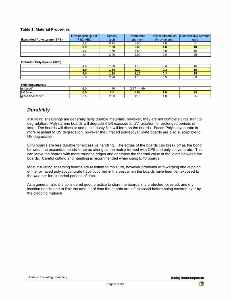
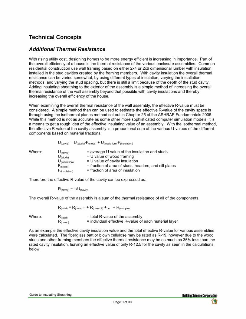
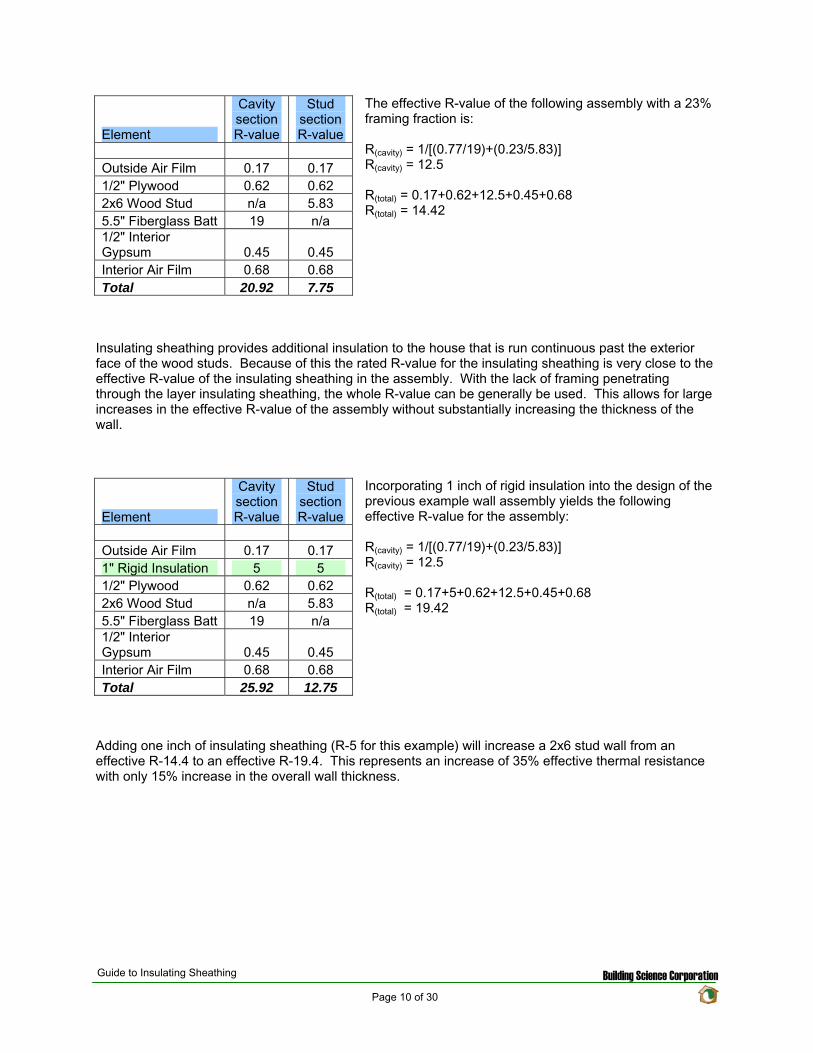
Element
Cavity section R-value
Stud section R-value
Outside Air Film 017 017 12 Plywood 062 062 2x6 Wood Stud na 583 55 Fiberglass Batt 19 na 12 Interior Gypsum 045 045 Interior Air Film 068 068 Total 2092 775
The effective R-value of the following assembly with a 23 framing fraction is
R(cavity) = 1[(07719)+(023583)] R(cavity) = 125
R(total) = 017+062+125+045+068 R(total) = 1442
Insulating sheathing provides additional insulation to the house that is run continuous past the exterior face of the wood studs Because of this the rated R-value for the insulating sheathing is very close to the effective R-value of the insulating sheathing in the assembly With the lack of framing penetrating through the layer insulating sheathing the whole R-value can be generally be used This allows for large increases in the effective R-value of the assembly without substantially increasing the thickness of the wall
Incorporating 1 inch of rigid insulation into the design of the previous example wall assembly yields the following effective R-value for the assembly
R(cavity) = 1[(07719)+(023583)] R(cavity) = 125
R(total) = 017+5+062+125+045+068 R(total) = 1942
Element
Cavity section R-value
Stud section R-value
Outside Air Film 017 017 1 Rigid Insulation 5 5 12 Plywood 062 062 2x6 Wood Stud na 583 55 Fiberglass Batt 19 na 12 Interior Gypsum 045 045 Interior Air Film 068 068 Total 2592 1275
Adding one inch of insulating sheathing (R-5 for this example) will increase a 2x6 stud wall from an effective R-144 to an effective R-194 This represents an increase of 35 effective thermal resistance with only 15 increase in the overall wall thickness
Guide to Insulating Sheathing Building Science Corporation Page 10 of 30
Element Cavity Stud
Outside Air Film 017 017 1 Rigid Insulation 5 5 2x6 Wood Stud na 583 55 Fiberglass Batt 19 na 12 Interior Gypsum 045 045 Interior Air Film 068 068 Total 253 1213
If the insulating sheathing is used as the primary sheathing (eliminating the plywood or OSB from the exterior)
R(cavity) = 1[(07719)+(023583)] R(cavity) = 125
R(total) = 017+5+125+045+068 R(total) = 1880
With this configuration the wall thickness is only increased by 8 while the effective thermal resistance increases from R-144 to R-188 a 31 increase
Element
Cavity section R-value
Stud section R-value
Outside Air Film 017 017 2 Rigid Insulation 10 10 2x6 Wood Stud na 583 55 Fiberglass Batt 19 na 12 Interior Gypsum 045 045 Interior Air Film 068 068 Total 303 1713
Incorporating 2 inches of rigid insulation into the design of the example wall assembly yields the following effective R-value for the assembly
R(cavity) = 1[(07719)+(023583)] R(cavity) = 125
R(total) = 017+10+125+045+068 R(total) = 2380
Adding two inches of rigid insulation to the exterior (R-10) will increase the effective R-value from R-144 to R-238 This represents an increase of 65 over the original effective R-value
copy buildingsciencecom
Guide to Insulating Sheathing Building Science Corporation Page 11 of 30
Rain Water Management
For most climate zones the management of exterior rain water is the most critical aspect of the moisture management system of the building enclosure The fundamental principle of water management is to drain the water downwards and outwards out of the building and away from the building In order for the building and building assemblies to drain properly detailing of the drainage plane must be carefully designed
There are several options for creating a drainage plane in the wall assembly The choice of which method to use is based on weighing the risks involved
Water Resistance
As the water penetration resistance of the assembly increases the risk of moisture problems decreases
Moisture Tolerance of Assembly
As the moisture tolerance of the materials that comprise the assembly increases (masonry and concrete vs wood and steel) the risk of moisture related problems decreases
Exposure
As the exposure to rainfall increases the risk of moisture related problems increases
Rainfall
As the amount of rainfall increases the risk of moisture related problems increases
Drying Potential
As the ability of an assembly to dry increases due to the climate design or both the risk of moisture related problems decreases
Workmanship
As the craftsmanship of the construction of the assemblies and their connection details increases the risk of moisture related problems decreases
Guide to Insulating Sheathing Building Science Corporation Page 12 of 30
There are four strategies proposed for maintaining the continuity of the drainage plane with the incorporation of insulating sheathing to the exterior
Wall Section 1 - Insulating Sheathing and Housewrap over Plywood or OSB The first strategy involves installing the insulating sheathing over top of a layer of building paper or housewrap and wood sheathing This is the most durable assembly proposed in this guide as the drainage plane material (building paper or house wrap) is supported by the plywood sheathing and protected against wind loading and other environmental factors by the insulating sheathing This type of assembly would be recommended in areas or high exposure and rainfall
copy buildingsciencecom
copy buildingsciencecom
copy buildingsciencecom
copy buildingsciencecom
Wall Section 2 - Insulation Sheathing and Housewrap over Wood Studs The next proposed strategy is to install the insulating sheathing overtop of a housewrap that is stretched over wood studs In this configuration the housewrap drainage plane is protected from exterior elements (excessive wind loading and rain exposure) The type of assembly would work effectively in most rainfall zones though potentially not in high exposure locations With the lack of wood sheathing support on the exterior of the framing more care is required during the installation of the housewrap and insulating sheathing
Wall Section 3 - Housewrap installed over Insulating Sheathing and Wood Studs The third strategy would be to install the housewrap to the exterior of the insulating sheathing essentially replacing the plywood or OSB in a traditional wall assembly with insulating sheathing The housewrap is more exposed to exterior elements such as wind loading and moisture and may not be as durable as the other approaches In addition the fasteners used to install the housewrap must be able to penetrate all the way through the insulating sheathing and into the wood studs beyond This wall approach would function adequately in most rainfall zones
Wall Section 4 - Insulating Sheathing as the Drainage Plane The final approach would be to use the insulating sheathing as the primary sheathing and drainage plane of the assembly In order to achieve this all the vertical joints must be taped or sealed and special flashing details must be used With some question as to the long term dimensional stability of insulating sheathing products this approach is considered to be in the higher risk category and should only be used in areas with limited rainfall and exposure where rain water management is not as critical
Guide to Insulating Sheathing Building Science Corporation Page 13 of 30
Vapor Management
The design of the vapor management system should attempt to allow maximum drying of the wall assembly from diffusion while limiting the amount of moisture able to be driven into the assembly Where possible drying to both sides of the construction assembly is encourage however in some circumstances more stringent vapor control is required As a general rule for standard framed construction the vapor retarding layer should be placed to the interior of the assembly in cold climates (reducing the water vapor from the higher humidity interior air from diffusing into the assembly) while in hot humid climates the vapor retarding layer should be placed to the exterior of the assembly (reducing the water vapor from the hot humid outside air from diffusing into the assembly) copy buildingsciencecom
copy buildingsciencecom
copy buildingsciencecom
copy buildingsciencecom
Therefore in a general sense for cold climates it is preferable to use a more vapor permeable insulating sheathing (such as EPS and unfaced XPS) on the exterior and in hot humid climates it is preferable to use a more vapor impermeable sheathing on the exterior of the assembly (such as foil faced polyisocyanurate and plastic film faced XPS)
For mixed humid climates the system choices become more difficult as the assembly needs to be protected from wetting from both the interior as well as the exterior The drying can be predominantly to the exterior the interior or in both directions in a flow through type assembly Often these strategies need to be combined with other vapor management strategies such as building pressurization (or depressurization) and supplemental dehumidification There is also a strategy to place the vapor control layer towards the middle of the assembly This approach will be discussed in the next section on Condensation Resistance
There are also some exceptions With absorptive claddings such as brick veneer and stucco a high inward vapor drive can occur due to solar radiation heating up the wet cladding and creating a high vapor pressure difference between the brick (or stucco) and the exterior and the brick (or stucco) and the interior This vapor pressure differential will cause moisture to be driven into the assembly if there is not adequate vapor control on the exterior For this reason insulating sheathing that is installed behind a masonry veneer or stucco should be vapor semi-impermeable or it can be semi-permeable if combined with an impermeable or semi-impermeable membrane
Guide to Insulating Sheathing Building Science Corporation Page 14 of 30
copy buildingsciencecom
copy buildingsciencecom
copy buildingsciencecom
copy buildingsciencecom
Condensation Resistance
Condensation can occur when moisture laden air comes in contact with a material with a surface temperature below the dewpoint temperature of the air In a cold climate wall assembly this usually occurs at the interior face (or back side) of the exterior sheathing when moisture from the conditioned space penetrates into the wall assembly through vapor diffusion or air movement The addition of insulating sheathing to the exterior of an assembly in colder climates can provide for some condensation resistance within the wall assembly as it will change the thermal gradient through the assembly
The thermal gradient across an assembly describes how the temperature varies from one side of an assembly through to the other The thermal gradient can be predicted by examining the individual proportion of thermal resistance provided by each component Each different component will provide a percentage of the total thermal resistance of the assembly Therefore the change in temperature of any component is based on the percentage of thermal resistance provided by that component multiplied by the overall temperature difference across the assembly
∆T(comp) = R(comp) R(total) x (T(in) ndash T(out))
Where ∆T(comp) = temperature change across a component R(comp) = thermal resistance of the component R(total) = total thermal resistance of the assembly T(in) = interior temperature T(out) = exterior temperature
To determine the temperature at any given surface in the assembly the individual temperature changes across each component in the assembly up to the desired surface is added to the exterior temperature
T(surface) = T(out) + ∆T(comp 1) + ∆T(comp 2) + hellip + ∆T(comp n)
The example below examines the temperature of the inside surface of the exterior sheathing with an exterior temperature of 32F and an interior temperature of 70F For the first section below the temperature at the inside surface of the exterior sheathing would be calculated as
T(surface) = T(out) + ∆T(exterior air film) + ∆T(plywood)
T(surface) = 32 + [0172092 x (68-32)] + [0622092 x (68-32)] T(surface) = 32 + [00081 x 38] + [00296 x 38] T(surface) = 32 + 031 + 113 T(surface) = 3344 F
Guide to Insulating Sheathing Building Science Corporation Page 15 of 30
For the next two sections the temperature of the inside surface of the exterior sheathing is 3977 F and 4474 F respectively
copy buildingsciencecom
copy buildingsciencecom
copy buildingsciencecom
copy buildingsciencecom
As it can be seen from the figure above with the additional thermal resistance of the rigid board insulation material the temperature of the inside face of the sheathing will be warmer in the winter months than with traditional wood sheathing alone Since the surface temperature is warmer there is less of a risk of condensation forming on the inside face If the exterior wood sheathing eliminated the system becomes even more durable as insulation sheathings are resistant to water and will not degrade if a small amount of condensation does occur
For this to be applied effectively understanding the climate zone and the interior environmental conditions in which the assembly is being designed is very important As an example three different wall sections were examined in three different locations In each example the interior conditions were set at 70F and 35 Relative Humidity Air under these conditions will have a dew point of approximately 40F (determined from the psychometric chart) Also each assembly was assumed to have a vapor permeable interior finish or no effective interior air barrier layer allowing for the more humid interior air to come in contact with the interior face (condensing layer) of the exterior sheathing
The three wall sections were analyzed for the Chicago IL area with the exterior conditions based on the average monthly temperatures for a one year cycle The first wall section designed under the traditional approach with wood sheathing is at risk of condensation accumulation on the back of the wood sheathing from the middle of November to the middle of March (this is shown by the segment of the temperature profile that drops below the dewpoint of 40F for the interior air) With the addition of 1 inch of insulating sheathing the time period of condensation potential time is now from the middle of December to the middle of February The addition of 2 inches of insulating sheathing the temperature profile does not drop below the dewpoint temperature and therefore no longer at risk With 2 inches of insulating sheathing the wall assembly would not require an interior vapor control layer or interior continuous air seal
Guide to Insulating Sheathing Building Science Corporation Page 16 of 30
copy buildingsciencecom
copy buildingsciencecom
copy buildingsciencecom
copy buildingsciencecom
0
10
20
30
40
50
60
70
80
July
Augu
st
Septem
ber
Octo
ber
Novem
ber
Decem
ber
Janu
ary
Februa
ry
March
April
May
June
Ju
ly
Interior
Exterior
Condensing Surface Wall 1
Condensing Surface Wall 2
Condensing Surface Wall 3
Dew Point at 70F and 35RH
If the wall sections are moved to Minneapolis MN exterior insulating is no longer adequate on itrsquos own to manage the condensation resistance of the wall assembly For each profile an interior vapor control layer and air barrier would be required
0
10
20
30
40
50
60
70
80
July
Augu
st
Septem
ber
Octo
ber
Novem
ber
Decem
ber
Janu
ary
Februa
ry
March
April
May
June
Ju
ly
Interior
Exterior
Condensing Surface Wall 1
Condensing Surface Wall 2
Condensing Surface Wall 3
Dew Point at 70F and 35RH
Conversely if the profiles are moved to Seattle WA the exterior conditions are not cold enough to create problems with condensation even with the traditional approach (as long as the interior relative humidity is maintained below 35 RH)
Guide to Insulating Sheathing Building Science Corporation Page 17 of 30
copy buildingsciencecom
copy buildingsciencecom
copy buildingsciencecom
copy buildingsciencecom
0
10
20
30
40
50
60
70
80
July
Augu
st
Septem
ber
Octo
ber
Novem
ber
Decem
ber
Janu
ary
Februa
ry
March
April
May
June
Ju
ly
Interior
Exterior
Condensing Surface Wall 1
Condensing Surface Wall 2
Condensing Surface Wall 3
Dew Point at 70F and 35 RH
If the interior conditions change the condensation potential will also change Reexamining the Chicago IL sections once again and varying the interior relative humidity demonstrates that 1 inch of insulating sheathing would be adequate if the relative humidity was kept below 25 (dewpoint of 32F ) or that 2 inches of insulating sheathing would not be adequate if the interior relative humidity increases to 50 (dewpoint of 50F)
0 10
20 30 40
50 60
70 80
July
Augu
st
Septem
ber
Octo
ber
Novem
ber
Decem
ber
Janu
ary
Februa
ry
March
April
May
June
Ju
ly
Interior
Exterior
Condensing Surface Wall 1
Condensing Surface Wall 2
Condensing Surface Wall 3
Dew Point at 70F and 35 RH
Dew Point at 70F and 25 RH
Dew Point at 70F and 50 RH
While the use of insulating sheathing can help to reduce the condensation potential it is only a component in the overall design of the building enclosure assembly The examples above were used to demonstrate how insulating sheathing can reduce the condensation potential in an assembly however design of the building enclosure will likely include other water air and vapor management strategies as well
As mentioned earlier in mixed humid climates the thermal gradient approach can be used as part of the vapor management strategy The use of impermeable insulating sheathing materials of adequate thickness to ensure that the dewpoint temperature is not reached within the assembly will allow for the interior vapor control layer to be eliminated from the assembly (installing a vapor retarder on the interior would actually be detrimental to the system) With the impermeable or semi-impermeable nature of the
Guide to Insulating Sheathing Building Science Corporation Page 18 of 30
sheathing the exterior face of the board would function as a vapor retarder during the cooling month while the interior face of the insulating sheathing would function as a vapor retarder in the heating months The air barrier for the system could also be installed to the interior or exterior of the assembly This approach should also be combined with a slight positive interior pressure to limit the amount of infiltration of moist air during the cooling season as well as some interior moisture control to ensure that the interior RH does not exceed the maximum levels to prevent condensation on the interior surface of the exterior sheathing during the heating season
copy buildingsciencecom
copy buildingsciencecom
copy buildingsciencecom
copy buildingsciencecom
Guide to Insulating Sheathing Building Science Corporation Page 19 of 30
Design and Construction
The following four wall sections are used as the basis for discussion for this section
copy buildingsciencecom
copy buildingsciencecom
copy buildingsciencecom
copy buildingsciencecom
General Installation
Insulating sheathing should be installed based on manufacturerrsquos recommendations for fastener type and amount It is recommended to layout the insulating sheathing such that vertical joints do not occur at the corners of window and door openings or over window heads if possible
In Wall Section 1 and Wall Section 2 the primary drainage plane occurs behind the insulating sheathing All water management details (flashing and window installation details) should be tied back to the plane of the housewrap In these configurations while the insulating sheathing is not officially considered to be part of the drainage system of the wall it will provide some protection for the housewrap in preventing much of the exterior rain water that penetrates past the cladding from penetrating through to the actual drainage plane
For Wall Section 3 the primary drainage plane to the exterior of the insulating sheathing and more exposed to the elements In this configuration the water management and window installation details are integrated into the housewrap at the exterior face of the insulating sheathing Water management details would be the same as normal details of recommended good practice for wood sheathed house design
Wall Section 4 requires some special detailing All the joints between the insulation boards must be designed in such a way as to prevent water from penetrating past the exterior face of the insulation Sealing or taping the vertical joints should be done and if possible products that use shingle lapped or tongue and groove joints should be used A polyethylene flashing is recommended to be installed at the horizontal joints in the system
Guide to Insulating Sheathing Building Science Corporation Page 20 of 30
In order for the insulation sheathing to be used as a water resistive barrier the vertical plane of the exterior face of the sheathing must be as continuous as possible This is to prevent locations within the wall assembly where drainage could be blocked or where water might be held
copy buildingsciencecom
copy buildingsciencecom
copy buildingsciencecom
copy buildingsciencecom
For added protecting window head flashing and roof step flashings can be easily regletted into the face of the foam sheathing providing for better protection against flashing failure and reverse flashing problems The reglette should only penetrate into the face of the sheathing and not all the way through the sheathing
Cladding Attachment
For siding systems (wood vinyl and fiber cement) and masonry veneers there is virtually no change from standard recommended practice for cladding attachment details One of the only differences is that all fasteners must be installed through to the studs as insulating sheathing does not have adequate structural capacity both in shear and pull out strength
For Wall Section 1 and Wall Section 2 cladding systems such as traditional hard coat stucco (including thin brick and manufactured stone veneer) and acrylic stucco can be directly applied to the insulation board With these types of systems it is recommended to use drained insulation boards (ones with vertical grooves cut in the back) or to use a vertically textured (or profiled) housewrap to ensure that there is a drainage space behind the rigid board
For Wall Section 3 and Wall Section 4 traditional hard coat stucco (including thin brick and manufactured stone veneer) should NOT be installed without the addition of at least one layer of building paper or house wrap between the stucco renderings and the housewrap or drainage plane sheathing to act as a bond break
Roof Connection
Popular roof construction types will vary from one region to another Much of the country relies on sloped roof assemblies with eave overhangs In other areas flat roof construction is more common The roof wall connection will vary therefore depending on the type of roof assembly used
In sloped roof applications the insulating sheathing is installed up to the underside of the roof truss If desired the insulating sheathing can be notched around the roof trusses to act as a wind shield for the attic insulation
For Wall Section 1 and Wall Section 2 at gable ends and parapets the insulating sheathing is not required to extend to the full height of the construction since the drainage plane is maintained behind the insulation through the use of a housewrap Due to this the insulating sheathing can be stopped at the top of the plane of attic insulation However it may be convenient to extend the insulating sheathing the full height to simplify the cladding attachment at these areas Otherwise alternative methods to fur out and support the cladding will be required
Conversely For Wall Section 3 and Wall Section 4 the continuity of the drainage plane must be maintained to the exterior of the insulating sheathing For these wall sections often the simplest way to maintain the continuity of the drainage plane is to install the insulating sheathing up to the top of the parapet or over the gable end An alternative method for maintaining the drainage plane is to use a thin profile structural sheathing furred out and installed so that it is in plane or proud of the insulating sheathing to maintain the continuity of the drainage plane
Guide to Insulating Sheathing Building Science Corporation Page 21 of 30
copy buildingsciencecom
copy buildingsciencecom
copy buildingsciencecom
copy buildingsciencecom
Foundations Connection
The installation details for insulating sheathing at foundations are generally the same for all foundation types The intention is to continue the sheathing past the top edge of the foundation or basement wall to create a shingle lap with the foundation For walls with brick veneer this may not be possible In this situation a seat should be cast into the top of the foundation wall so that the brick and the insulation sheathing terminate at a level below the bottom plate of the stud wall This will allow a shingle lap joint to be created
Guide to Insulating Sheathing Building Science Corporation Page 22 of 30
copy buildingsciencecom
copy buildingsciencecom
copy buildingsciencecom
copy buildingsciencecom
Guide to Insulating Sheathing Building Science Corporation Page 23 of 30
Window installation
The following window installation sequence details is applicable to Wall Section 1 (Wall Section 2 details would be almost identical ndash with the elimination of wood sheathing behind the housewrap)
copy buildingsciencecom
copy buildingsciencecom
copy buildingsciencecom
copy buildingsciencecom
1 Wood frame wall with OSB and housewrap 2 Modified ldquoIrdquo cut in housewrap 3 Housewrap folded in at jambs and sill Housewrap at head temporarily folded up or alternatively
tucked under Install backdam
4 Install adhesive backed sill flashing and corner flashing patches at sill 5 Apply sealant at jambs head and sill Alternatively sealant can be applied to the back side of the
nailing flange (sealants housewraps and flashings must be chemically compatible) 6 Install window plumb level and square as per manufacturerrsquos instructions
Guide to Insulating Sheathing Building Science Corporation Page 24 of 30
copy buildingsciencecom
copy buildingsciencecom
copy buildingsciencecom
copy buildingsciencecom
7 Install jamb flashing first Install a drip cap (if applicable) Install head flashing 8 Fold down head housewrap 9 Apply corner patches at head Air seal window around the entire perimeter on the interior with
sealant or non-expanding foam Install foam sheathing over housewrap
Guide to Insulating Sheathing Building Science Corporation Page 25 of 30
The following window installation sequence details are applicable to Wall Section 4 (Wall Section 3 details would be almost identical ndash addition of housewrap to the exterior of the insulating sheathing prior to window rough opening preparation)
copy buildingsciencecom
copy buildingsciencecom
copy buildingsciencecom
copy buildingsciencecom
1 Install foam sheathing on wood frame wall 2 Install backdam 3 Install first piece of adhesive backed sill flashing apply second piece of adhesive backed sill
flashing
4 Install corner flashing patches at sill 5 Install adhesive backed jamb flashings (jamb flashing adhered to foam and stapled to frame) 6 Apply sealant at jambs head and sill Alternatively sealant can be applied to the back side of the
nailing flange (sealants housewraps and flashings must be chemically compatible)
Guide to Insulating Sheathing Building Science Corporation Page 26 of 30
copy buildingsciencecom
copy buildingsciencecom
copy buildingsciencecom
copy buildingsciencecom
7 Install window plumb level and square as per manufacturerrsquos instructions 8 Install jamb flashing 9 Install drip cap (if applicable) install head flashing tape head flashing air seal around the
perimeter on the interior with sealant or low expanding foam
Guide to Insulating Sheathing Building Science Corporation Page 27 of 30
copy buildingsciencecom
copy buildingsciencecom
copy buildingsciencecom
copy buildingsciencecom
Related Concepts
Advanced Framing
The use of advanced framing with insulation sheathing is another concept used to reduce the amount of materials in residential construction The layout of the sheathing boards over the area of the wall framing should be done to minimize the amount of cutting of the material and construction waste created
wall
Single top plate
studs by rim
Single
rough
support will be required under point
solid blocking
Two stud corners
No headers in non-bearing
stud at
opening
No cripples under window opening
Header hangers instead of jack studs (see Figure 55)
Roof framingtrusses line up with wall
and floor framing
Insulated header
Single top plate
Point load transferred between
closure material acting as header If rim closure material is non-structural
loads Use
between joists
This will impact the effective thermal resistance of the wall assembly as well Standard residential construction will end up with a framing fraction for the wall assemblies of around 23 of the wall area With advanced framing this fraction can be reduced down to approximately 16 and sometimes even less If we reexamine the techniques for calculating the effective R-value of the assembly as used in the Thermal Resistance section we obtain the following results
Guide to Insulating Sheathing Building Science Corporation Page 28 of 30
copy buildingsciencecom
copy buildingsciencecom
copy buildingsciencecom
copy buildingsciencecom
Element
Cavity Section R-value
Stud Section R-value
Outside Air Film 017 017 1 Rigid Insulation 5 5 2x6 Wood Stud na 583 55 Fiberglass Batt 19 na 12 Interior Gypsum 045 045 Interior Air Film 068 068 Total 253 1213
The effective R-value of the following assembly with a 16 framing fraction is
R(cavity) = 1[(08419)+(016583)] R(cavity) = 1396
R(total) = 017+062+1396+045+068 R(total) = 2026
The same effective R-value with a 23 framing fraction yielded a total R-value of 1880 This represents a 78 increase in thermal resistance for the entire assembly
Cross Bracing and Inset Shear Panels
In Wall Sections 2 3 and 4 the regular method for shear resistance has been removed from the assembly (traditionally wood sheathing over the exterior of the building) Due to this alternative methods for providing shear resistance must be incorporated into the design
A common approach is to install exterior structural wood sheathing at the corners and at regular intervals as needed to provide for the lateral load resistance requirements for the location (wind and seismic) Installing the structural wood sheathing to exterior interferes with the installation of the insulating sheathing This can create problems with drainage plane continuity and thermal bridging (due to the reduction in insulation thickness)
The recommendation is to use systems and techniques that can be installed flush with the exterior face of the wood studs This way the insulation can be installed in a continuous uniform thickness over the entire exterior wall area Some of the methods to achieve this are through the use of metal cross bracing or inset shear panels
Guide to Insulating Sheathing Building Science Corporation Page 29 of 30
With metal cross bracing the thickness of the metal braces are insignificant and do not interfere with the installation of the insulating sheathing The capacity of the metal cross bracing however may not be adequate for areas with high wind loads andor seismic activity In these locations a more robust form of lateral load resistance may be needed
copy buildingsciencecom
copy buildingsciencecom
copy buildingsciencecom
copy buildingsciencecom
Inset shear panels can provide for high levels of lateral load resistance and can be used in all wind and seismic zones Inset shear panels are wood framed panels that fit within the stud spacing of the wall assembly In this way the exterior face of the panel is flush with the exterior face of the wood studs
Depending on the area of the country different requirements for wind and seismic resistance are required The method chosen will depend on the individual code requirements for the area
Guide to Insulating Sheathing Building Science Corporation Page 30 of 30
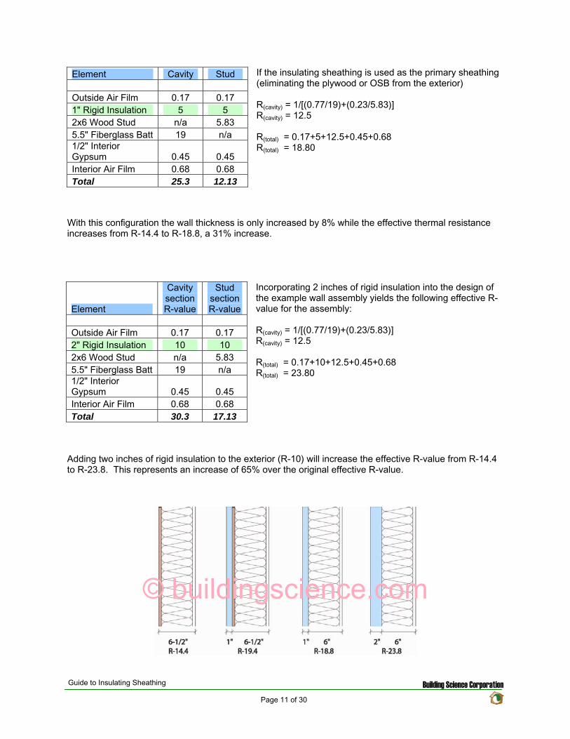
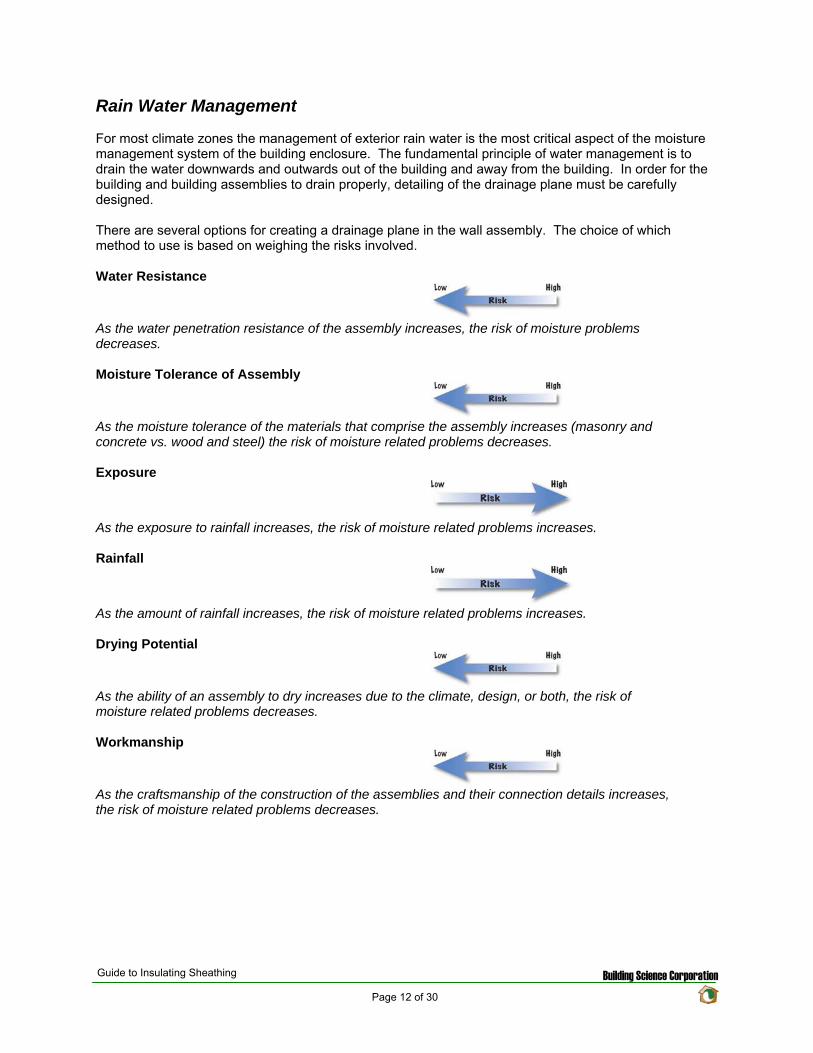
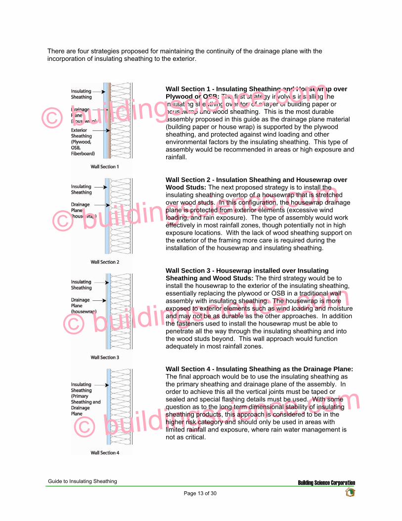
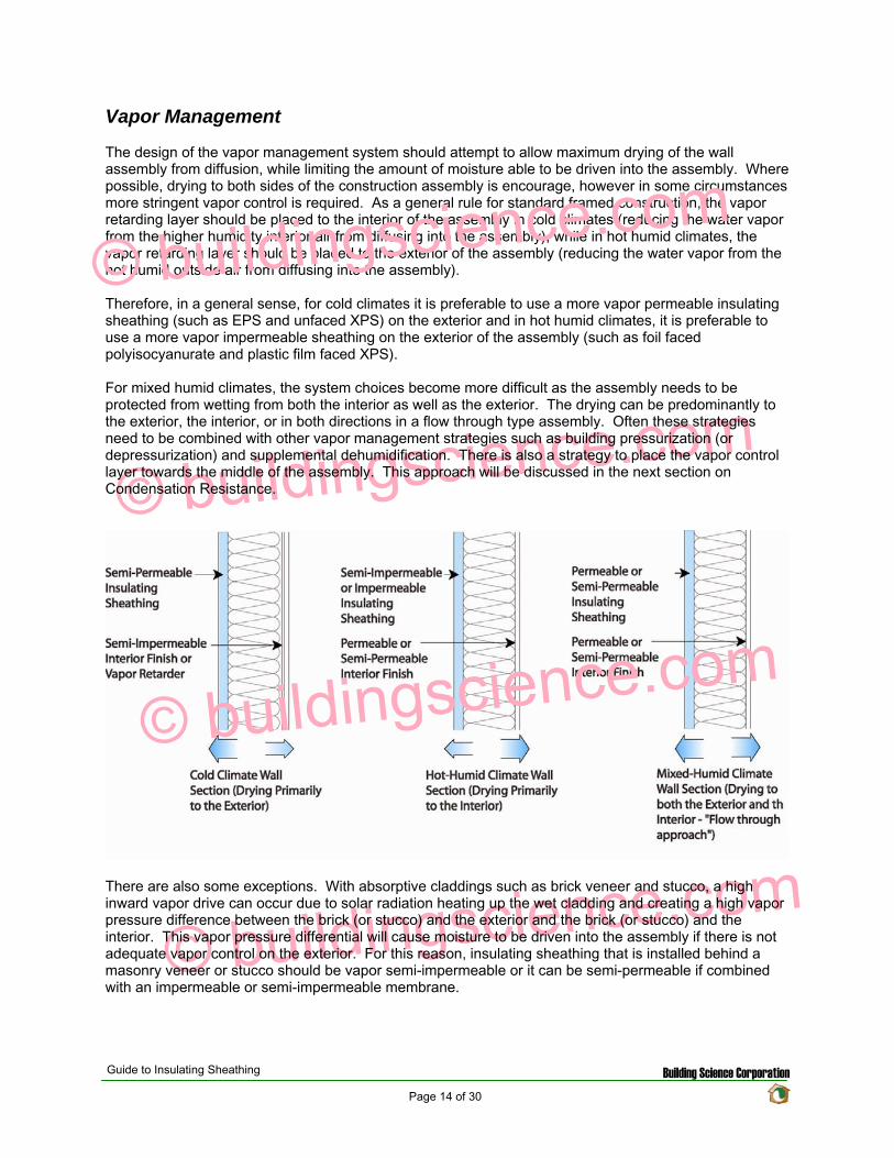
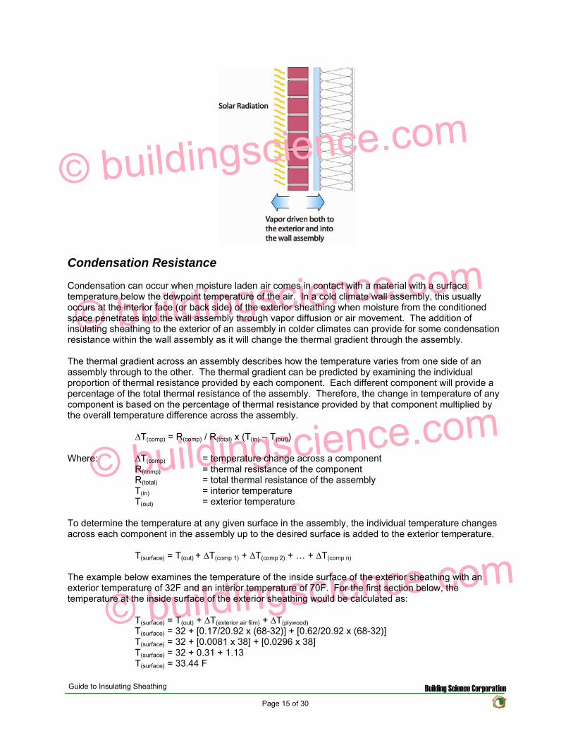
copy buildingsciencecom
copy buildingsciencecom
copy buildingsciencecom
copy buildingsciencecom
Condensation Resistance
Condensation can occur when moisture laden air comes in contact with a material with a surface temperature below the dewpoint temperature of the air In a cold climate wall assembly this usually occurs at the interior face (or back side) of the exterior sheathing when moisture from the conditioned space penetrates into the wall assembly through vapor diffusion or air movement The addition of insulating sheathing to the exterior of an assembly in colder climates can provide for some condensation resistance within the wall assembly as it will change the thermal gradient through the assembly
The thermal gradient across an assembly describes how the temperature varies from one side of an assembly through to the other The thermal gradient can be predicted by examining the individual proportion of thermal resistance provided by each component Each different component will provide a percentage of the total thermal resistance of the assembly Therefore the change in temperature of any component is based on the percentage of thermal resistance provided by that component multiplied by the overall temperature difference across the assembly
∆T(comp) = R(comp) R(total) x (T(in) ndash T(out))
Where ∆T(comp) = temperature change across a component R(comp) = thermal resistance of the component R(total) = total thermal resistance of the assembly T(in) = interior temperature T(out) = exterior temperature
To determine the temperature at any given surface in the assembly the individual temperature changes across each component in the assembly up to the desired surface is added to the exterior temperature
T(surface) = T(out) + ∆T(comp 1) + ∆T(comp 2) + hellip + ∆T(comp n)
The example below examines the temperature of the inside surface of the exterior sheathing with an exterior temperature of 32F and an interior temperature of 70F For the first section below the temperature at the inside surface of the exterior sheathing would be calculated as
T(surface) = T(out) + ∆T(exterior air film) + ∆T(plywood)
T(surface) = 32 + [0172092 x (68-32)] + [0622092 x (68-32)] T(surface) = 32 + [00081 x 38] + [00296 x 38] T(surface) = 32 + 031 + 113 T(surface) = 3344 F
Guide to Insulating Sheathing Building Science Corporation Page 15 of 30
For the next two sections the temperature of the inside surface of the exterior sheathing is 3977 F and 4474 F respectively
copy buildingsciencecom
copy buildingsciencecom
copy buildingsciencecom
copy buildingsciencecom
As it can be seen from the figure above with the additional thermal resistance of the rigid board insulation material the temperature of the inside face of the sheathing will be warmer in the winter months than with traditional wood sheathing alone Since the surface temperature is warmer there is less of a risk of condensation forming on the inside face If the exterior wood sheathing eliminated the system becomes even more durable as insulation sheathings are resistant to water and will not degrade if a small amount of condensation does occur
For this to be applied effectively understanding the climate zone and the interior environmental conditions in which the assembly is being designed is very important As an example three different wall sections were examined in three different locations In each example the interior conditions were set at 70F and 35 Relative Humidity Air under these conditions will have a dew point of approximately 40F (determined from the psychometric chart) Also each assembly was assumed to have a vapor permeable interior finish or no effective interior air barrier layer allowing for the more humid interior air to come in contact with the interior face (condensing layer) of the exterior sheathing
The three wall sections were analyzed for the Chicago IL area with the exterior conditions based on the average monthly temperatures for a one year cycle The first wall section designed under the traditional approach with wood sheathing is at risk of condensation accumulation on the back of the wood sheathing from the middle of November to the middle of March (this is shown by the segment of the temperature profile that drops below the dewpoint of 40F for the interior air) With the addition of 1 inch of insulating sheathing the time period of condensation potential time is now from the middle of December to the middle of February The addition of 2 inches of insulating sheathing the temperature profile does not drop below the dewpoint temperature and therefore no longer at risk With 2 inches of insulating sheathing the wall assembly would not require an interior vapor control layer or interior continuous air seal
Guide to Insulating Sheathing Building Science Corporation Page 16 of 30
copy buildingsciencecom
copy buildingsciencecom
copy buildingsciencecom
copy buildingsciencecom
0
10
20
30
40
50
60
70
80
July
Augu
st
Septem
ber
Octo
ber
Novem
ber
Decem
ber
Janu
ary
Februa
ry
March
April
May
June
Ju
ly
Interior
Exterior
Condensing Surface Wall 1
Condensing Surface Wall 2
Condensing Surface Wall 3
Dew Point at 70F and 35RH
If the wall sections are moved to Minneapolis MN exterior insulating is no longer adequate on itrsquos own to manage the condensation resistance of the wall assembly For each profile an interior vapor control layer and air barrier would be required
0
10
20
30
40
50
60
70
80
July
Augu
st
Septem
ber
Octo
ber
Novem
ber
Decem
ber
Janu
ary
Februa
ry
March
April
May
June
Ju
ly
Interior
Exterior
Condensing Surface Wall 1
Condensing Surface Wall 2
Condensing Surface Wall 3
Dew Point at 70F and 35RH
Conversely if the profiles are moved to Seattle WA the exterior conditions are not cold enough to create problems with condensation even with the traditional approach (as long as the interior relative humidity is maintained below 35 RH)
Guide to Insulating Sheathing Building Science Corporation Page 17 of 30
copy buildingsciencecom
copy buildingsciencecom
copy buildingsciencecom
copy buildingsciencecom
0
10
20
30
40
50
60
70
80
July
Augu
st
Septem
ber
Octo
ber
Novem
ber
Decem
ber
Janu
ary
Februa
ry
March
April
May
June
Ju
ly
Interior
Exterior
Condensing Surface Wall 1
Condensing Surface Wall 2
Condensing Surface Wall 3
Dew Point at 70F and 35 RH
If the interior conditions change the condensation potential will also change Reexamining the Chicago IL sections once again and varying the interior relative humidity demonstrates that 1 inch of insulating sheathing would be adequate if the relative humidity was kept below 25 (dewpoint of 32F ) or that 2 inches of insulating sheathing would not be adequate if the interior relative humidity increases to 50 (dewpoint of 50F)
0 10
20 30 40
50 60
70 80
July
Augu
st
Septem
ber
Octo
ber
Novem
ber
Decem
ber
Janu
ary
Februa
ry
March
April
May
June
Ju
ly
Interior
Exterior
Condensing Surface Wall 1
Condensing Surface Wall 2
Condensing Surface Wall 3
Dew Point at 70F and 35 RH
Dew Point at 70F and 25 RH
Dew Point at 70F and 50 RH
While the use of insulating sheathing can help to reduce the condensation potential it is only a component in the overall design of the building enclosure assembly The examples above were used to demonstrate how insulating sheathing can reduce the condensation potential in an assembly however design of the building enclosure will likely include other water air and vapor management strategies as well
As mentioned earlier in mixed humid climates the thermal gradient approach can be used as part of the vapor management strategy The use of impermeable insulating sheathing materials of adequate thickness to ensure that the dewpoint temperature is not reached within the assembly will allow for the interior vapor control layer to be eliminated from the assembly (installing a vapor retarder on the interior would actually be detrimental to the system) With the impermeable or semi-impermeable nature of the
Guide to Insulating Sheathing Building Science Corporation Page 18 of 30
sheathing the exterior face of the board would function as a vapor retarder during the cooling month while the interior face of the insulating sheathing would function as a vapor retarder in the heating months The air barrier for the system could also be installed to the interior or exterior of the assembly This approach should also be combined with a slight positive interior pressure to limit the amount of infiltration of moist air during the cooling season as well as some interior moisture control to ensure that the interior RH does not exceed the maximum levels to prevent condensation on the interior surface of the exterior sheathing during the heating season
copy buildingsciencecom
copy buildingsciencecom
copy buildingsciencecom
copy buildingsciencecom
Guide to Insulating Sheathing Building Science Corporation Page 19 of 30
Design and Construction
The following four wall sections are used as the basis for discussion for this section
copy buildingsciencecom
copy buildingsciencecom
copy buildingsciencecom
copy buildingsciencecom
General Installation
Insulating sheathing should be installed based on manufacturerrsquos recommendations for fastener type and amount It is recommended to layout the insulating sheathing such that vertical joints do not occur at the corners of window and door openings or over window heads if possible
In Wall Section 1 and Wall Section 2 the primary drainage plane occurs behind the insulating sheathing All water management details (flashing and window installation details) should be tied back to the plane of the housewrap In these configurations while the insulating sheathing is not officially considered to be part of the drainage system of the wall it will provide some protection for the housewrap in preventing much of the exterior rain water that penetrates past the cladding from penetrating through to the actual drainage plane
For Wall Section 3 the primary drainage plane to the exterior of the insulating sheathing and more exposed to the elements In this configuration the water management and window installation details are integrated into the housewrap at the exterior face of the insulating sheathing Water management details would be the same as normal details of recommended good practice for wood sheathed house design
Wall Section 4 requires some special detailing All the joints between the insulation boards must be designed in such a way as to prevent water from penetrating past the exterior face of the insulation Sealing or taping the vertical joints should be done and if possible products that use shingle lapped or tongue and groove joints should be used A polyethylene flashing is recommended to be installed at the horizontal joints in the system
Guide to Insulating Sheathing Building Science Corporation Page 20 of 30
In order for the insulation sheathing to be used as a water resistive barrier the vertical plane of the exterior face of the sheathing must be as continuous as possible This is to prevent locations within the wall assembly where drainage could be blocked or where water might be held
copy buildingsciencecom
copy buildingsciencecom
copy buildingsciencecom
copy buildingsciencecom
For added protecting window head flashing and roof step flashings can be easily regletted into the face of the foam sheathing providing for better protection against flashing failure and reverse flashing problems The reglette should only penetrate into the face of the sheathing and not all the way through the sheathing
Cladding Attachment
For siding systems (wood vinyl and fiber cement) and masonry veneers there is virtually no change from standard recommended practice for cladding attachment details One of the only differences is that all fasteners must be installed through to the studs as insulating sheathing does not have adequate structural capacity both in shear and pull out strength
For Wall Section 1 and Wall Section 2 cladding systems such as traditional hard coat stucco (including thin brick and manufactured stone veneer) and acrylic stucco can be directly applied to the insulation board With these types of systems it is recommended to use drained insulation boards (ones with vertical grooves cut in the back) or to use a vertically textured (or profiled) housewrap to ensure that there is a drainage space behind the rigid board
For Wall Section 3 and Wall Section 4 traditional hard coat stucco (including thin brick and manufactured stone veneer) should NOT be installed without the addition of at least one layer of building paper or house wrap between the stucco renderings and the housewrap or drainage plane sheathing to act as a bond break
Roof Connection
Popular roof construction types will vary from one region to another Much of the country relies on sloped roof assemblies with eave overhangs In other areas flat roof construction is more common The roof wall connection will vary therefore depending on the type of roof assembly used
In sloped roof applications the insulating sheathing is installed up to the underside of the roof truss If desired the insulating sheathing can be notched around the roof trusses to act as a wind shield for the attic insulation
For Wall Section 1 and Wall Section 2 at gable ends and parapets the insulating sheathing is not required to extend to the full height of the construction since the drainage plane is maintained behind the insulation through the use of a housewrap Due to this the insulating sheathing can be stopped at the top of the plane of attic insulation However it may be convenient to extend the insulating sheathing the full height to simplify the cladding attachment at these areas Otherwise alternative methods to fur out and support the cladding will be required
Conversely For Wall Section 3 and Wall Section 4 the continuity of the drainage plane must be maintained to the exterior of the insulating sheathing For these wall sections often the simplest way to maintain the continuity of the drainage plane is to install the insulating sheathing up to the top of the parapet or over the gable end An alternative method for maintaining the drainage plane is to use a thin profile structural sheathing furred out and installed so that it is in plane or proud of the insulating sheathing to maintain the continuity of the drainage plane
Guide to Insulating Sheathing Building Science Corporation Page 21 of 30
copy buildingsciencecom
copy buildingsciencecom
copy buildingsciencecom
copy buildingsciencecom
Foundations Connection
The installation details for insulating sheathing at foundations are generally the same for all foundation types The intention is to continue the sheathing past the top edge of the foundation or basement wall to create a shingle lap with the foundation For walls with brick veneer this may not be possible In this situation a seat should be cast into the top of the foundation wall so that the brick and the insulation sheathing terminate at a level below the bottom plate of the stud wall This will allow a shingle lap joint to be created
Guide to Insulating Sheathing Building Science Corporation Page 22 of 30
copy buildingsciencecom
copy buildingsciencecom
copy buildingsciencecom
copy buildingsciencecom
Guide to Insulating Sheathing Building Science Corporation Page 23 of 30
Window installation
The following window installation sequence details is applicable to Wall Section 1 (Wall Section 2 details would be almost identical ndash with the elimination of wood sheathing behind the housewrap)
copy buildingsciencecom
copy buildingsciencecom
copy buildingsciencecom
copy buildingsciencecom
1 Wood frame wall with OSB and housewrap 2 Modified ldquoIrdquo cut in housewrap 3 Housewrap folded in at jambs and sill Housewrap at head temporarily folded up or alternatively
tucked under Install backdam
4 Install adhesive backed sill flashing and corner flashing patches at sill 5 Apply sealant at jambs head and sill Alternatively sealant can be applied to the back side of the
nailing flange (sealants housewraps and flashings must be chemically compatible) 6 Install window plumb level and square as per manufacturerrsquos instructions
Guide to Insulating Sheathing Building Science Corporation Page 24 of 30
copy buildingsciencecom
copy buildingsciencecom
copy buildingsciencecom
copy buildingsciencecom
7 Install jamb flashing first Install a drip cap (if applicable) Install head flashing 8 Fold down head housewrap 9 Apply corner patches at head Air seal window around the entire perimeter on the interior with
sealant or non-expanding foam Install foam sheathing over housewrap
Guide to Insulating Sheathing Building Science Corporation Page 25 of 30
The following window installation sequence details are applicable to Wall Section 4 (Wall Section 3 details would be almost identical ndash addition of housewrap to the exterior of the insulating sheathing prior to window rough opening preparation)
copy buildingsciencecom
copy buildingsciencecom
copy buildingsciencecom
copy buildingsciencecom
1 Install foam sheathing on wood frame wall 2 Install backdam 3 Install first piece of adhesive backed sill flashing apply second piece of adhesive backed sill
flashing
4 Install corner flashing patches at sill 5 Install adhesive backed jamb flashings (jamb flashing adhered to foam and stapled to frame) 6 Apply sealant at jambs head and sill Alternatively sealant can be applied to the back side of the
nailing flange (sealants housewraps and flashings must be chemically compatible)
Guide to Insulating Sheathing Building Science Corporation Page 26 of 30
copy buildingsciencecom
copy buildingsciencecom
copy buildingsciencecom
copy buildingsciencecom
7 Install window plumb level and square as per manufacturerrsquos instructions 8 Install jamb flashing 9 Install drip cap (if applicable) install head flashing tape head flashing air seal around the
perimeter on the interior with sealant or low expanding foam
Guide to Insulating Sheathing Building Science Corporation Page 27 of 30
copy buildingsciencecom
copy buildingsciencecom
copy buildingsciencecom
copy buildingsciencecom
Related Concepts
Advanced Framing
The use of advanced framing with insulation sheathing is another concept used to reduce the amount of materials in residential construction The layout of the sheathing boards over the area of the wall framing should be done to minimize the amount of cutting of the material and construction waste created
wall
Single top plate
studs by rim
Single
rough
support will be required under point
solid blocking
Two stud corners
No headers in non-bearing
stud at
opening
No cripples under window opening
Header hangers instead of jack studs (see Figure 55)
Roof framingtrusses line up with wall
and floor framing
Insulated header
Single top plate
Point load transferred between
closure material acting as header If rim closure material is non-structural
loads Use
between joists
This will impact the effective thermal resistance of the wall assembly as well Standard residential construction will end up with a framing fraction for the wall assemblies of around 23 of the wall area With advanced framing this fraction can be reduced down to approximately 16 and sometimes even less If we reexamine the techniques for calculating the effective R-value of the assembly as used in the Thermal Resistance section we obtain the following results
Guide to Insulating Sheathing Building Science Corporation Page 28 of 30
copy buildingsciencecom
copy buildingsciencecom
copy buildingsciencecom
copy buildingsciencecom
Element
Cavity Section R-value
Stud Section R-value
Outside Air Film 017 017 1 Rigid Insulation 5 5 2x6 Wood Stud na 583 55 Fiberglass Batt 19 na 12 Interior Gypsum 045 045 Interior Air Film 068 068 Total 253 1213
The effective R-value of the following assembly with a 16 framing fraction is
R(cavity) = 1[(08419)+(016583)] R(cavity) = 1396
R(total) = 017+062+1396+045+068 R(total) = 2026
The same effective R-value with a 23 framing fraction yielded a total R-value of 1880 This represents a 78 increase in thermal resistance for the entire assembly
Cross Bracing and Inset Shear Panels
In Wall Sections 2 3 and 4 the regular method for shear resistance has been removed from the assembly (traditionally wood sheathing over the exterior of the building) Due to this alternative methods for providing shear resistance must be incorporated into the design
A common approach is to install exterior structural wood sheathing at the corners and at regular intervals as needed to provide for the lateral load resistance requirements for the location (wind and seismic) Installing the structural wood sheathing to exterior interferes with the installation of the insulating sheathing This can create problems with drainage plane continuity and thermal bridging (due to the reduction in insulation thickness)
The recommendation is to use systems and techniques that can be installed flush with the exterior face of the wood studs This way the insulation can be installed in a continuous uniform thickness over the entire exterior wall area Some of the methods to achieve this are through the use of metal cross bracing or inset shear panels
Guide to Insulating Sheathing Building Science Corporation Page 29 of 30
With metal cross bracing the thickness of the metal braces are insignificant and do not interfere with the installation of the insulating sheathing The capacity of the metal cross bracing however may not be adequate for areas with high wind loads andor seismic activity In these locations a more robust form of lateral load resistance may be needed
copy buildingsciencecom
copy buildingsciencecom
copy buildingsciencecom
copy buildingsciencecom
Inset shear panels can provide for high levels of lateral load resistance and can be used in all wind and seismic zones Inset shear panels are wood framed panels that fit within the stud spacing of the wall assembly In this way the exterior face of the panel is flush with the exterior face of the wood studs
Depending on the area of the country different requirements for wind and seismic resistance are required The method chosen will depend on the individual code requirements for the area
Guide to Insulating Sheathing Building Science Corporation Page 30 of 30
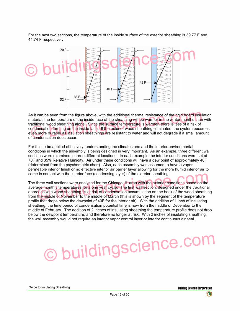
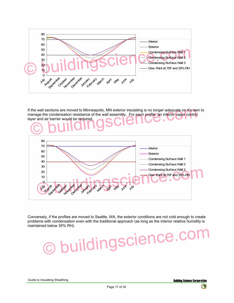
copy buildingsciencecom
copy buildingsciencecom
copy buildingsciencecom
copy buildingsciencecom
0
10
20
30
40
50
60
70
80
July
Augu
st
Septem
ber
Octo
ber
Novem
ber
Decem
ber
Janu
ary
Februa
ry
March
April
May
June
Ju
ly
Interior
Exterior
Condensing Surface Wall 1
Condensing Surface Wall 2
Condensing Surface Wall 3
Dew Point at 70F and 35RH
If the wall sections are moved to Minneapolis MN exterior insulating is no longer adequate on itrsquos own to manage the condensation resistance of the wall assembly For each profile an interior vapor control layer and air barrier would be required
0
10
20
30
40
50
60
70
80
July
Augu
st
Septem
ber
Octo
ber
Novem
ber
Decem
ber
Janu
ary
Februa
ry
March
April
May
June
Ju
ly
Interior
Exterior
Condensing Surface Wall 1
Condensing Surface Wall 2
Condensing Surface Wall 3
Dew Point at 70F and 35RH
Conversely if the profiles are moved to Seattle WA the exterior conditions are not cold enough to create problems with condensation even with the traditional approach (as long as the interior relative humidity is maintained below 35 RH)
Guide to Insulating Sheathing Building Science Corporation Page 17 of 30
copy buildingsciencecom
copy buildingsciencecom
copy buildingsciencecom
copy buildingsciencecom
0
10
20
30
40
50
60
70
80
July
Augu
st
Septem
ber
Octo
ber
Novem
ber
Decem
ber
Janu
ary
Februa
ry
March
April
May
June
Ju
ly
Interior
Exterior
Condensing Surface Wall 1
Condensing Surface Wall 2
Condensing Surface Wall 3
Dew Point at 70F and 35 RH
If the interior conditions change the condensation potential will also change Reexamining the Chicago IL sections once again and varying the interior relative humidity demonstrates that 1 inch of insulating sheathing would be adequate if the relative humidity was kept below 25 (dewpoint of 32F ) or that 2 inches of insulating sheathing would not be adequate if the interior relative humidity increases to 50 (dewpoint of 50F)
0 10
20 30 40
50 60
70 80
July
Augu
st
Septem
ber
Octo
ber
Novem
ber
Decem
ber
Janu
ary
Februa
ry
March
April
May
June
Ju
ly
Interior
Exterior
Condensing Surface Wall 1
Condensing Surface Wall 2
Condensing Surface Wall 3
Dew Point at 70F and 35 RH
Dew Point at 70F and 25 RH
Dew Point at 70F and 50 RH
While the use of insulating sheathing can help to reduce the condensation potential it is only a component in the overall design of the building enclosure assembly The examples above were used to demonstrate how insulating sheathing can reduce the condensation potential in an assembly however design of the building enclosure will likely include other water air and vapor management strategies as well
As mentioned earlier in mixed humid climates the thermal gradient approach can be used as part of the vapor management strategy The use of impermeable insulating sheathing materials of adequate thickness to ensure that the dewpoint temperature is not reached within the assembly will allow for the interior vapor control layer to be eliminated from the assembly (installing a vapor retarder on the interior would actually be detrimental to the system) With the impermeable or semi-impermeable nature of the
Guide to Insulating Sheathing Building Science Corporation Page 18 of 30
sheathing the exterior face of the board would function as a vapor retarder during the cooling month while the interior face of the insulating sheathing would function as a vapor retarder in the heating months The air barrier for the system could also be installed to the interior or exterior of the assembly This approach should also be combined with a slight positive interior pressure to limit the amount of infiltration of moist air during the cooling season as well as some interior moisture control to ensure that the interior RH does not exceed the maximum levels to prevent condensation on the interior surface of the exterior sheathing during the heating season
copy buildingsciencecom
copy buildingsciencecom
copy buildingsciencecom
copy buildingsciencecom
Guide to Insulating Sheathing Building Science Corporation Page 19 of 30
Design and Construction
The following four wall sections are used as the basis for discussion for this section
copy buildingsciencecom
copy buildingsciencecom
copy buildingsciencecom
copy buildingsciencecom
General Installation
Insulating sheathing should be installed based on manufacturerrsquos recommendations for fastener type and amount It is recommended to layout the insulating sheathing such that vertical joints do not occur at the corners of window and door openings or over window heads if possible
In Wall Section 1 and Wall Section 2 the primary drainage plane occurs behind the insulating sheathing All water management details (flashing and window installation details) should be tied back to the plane of the housewrap In these configurations while the insulating sheathing is not officially considered to be part of the drainage system of the wall it will provide some protection for the housewrap in preventing much of the exterior rain water that penetrates past the cladding from penetrating through to the actual drainage plane
For Wall Section 3 the primary drainage plane to the exterior of the insulating sheathing and more exposed to the elements In this configuration the water management and window installation details are integrated into the housewrap at the exterior face of the insulating sheathing Water management details would be the same as normal details of recommended good practice for wood sheathed house design
Wall Section 4 requires some special detailing All the joints between the insulation boards must be designed in such a way as to prevent water from penetrating past the exterior face of the insulation Sealing or taping the vertical joints should be done and if possible products that use shingle lapped or tongue and groove joints should be used A polyethylene flashing is recommended to be installed at the horizontal joints in the system
Guide to Insulating Sheathing Building Science Corporation Page 20 of 30
In order for the insulation sheathing to be used as a water resistive barrier the vertical plane of the exterior face of the sheathing must be as continuous as possible This is to prevent locations within the wall assembly where drainage could be blocked or where water might be held
copy buildingsciencecom
copy buildingsciencecom
copy buildingsciencecom
copy buildingsciencecom
For added protecting window head flashing and roof step flashings can be easily regletted into the face of the foam sheathing providing for better protection against flashing failure and reverse flashing problems The reglette should only penetrate into the face of the sheathing and not all the way through the sheathing
Cladding Attachment
For siding systems (wood vinyl and fiber cement) and masonry veneers there is virtually no change from standard recommended practice for cladding attachment details One of the only differences is that all fasteners must be installed through to the studs as insulating sheathing does not have adequate structural capacity both in shear and pull out strength
For Wall Section 1 and Wall Section 2 cladding systems such as traditional hard coat stucco (including thin brick and manufactured stone veneer) and acrylic stucco can be directly applied to the insulation board With these types of systems it is recommended to use drained insulation boards (ones with vertical grooves cut in the back) or to use a vertically textured (or profiled) housewrap to ensure that there is a drainage space behind the rigid board
For Wall Section 3 and Wall Section 4 traditional hard coat stucco (including thin brick and manufactured stone veneer) should NOT be installed without the addition of at least one layer of building paper or house wrap between the stucco renderings and the housewrap or drainage plane sheathing to act as a bond break
Roof Connection
Popular roof construction types will vary from one region to another Much of the country relies on sloped roof assemblies with eave overhangs In other areas flat roof construction is more common The roof wall connection will vary therefore depending on the type of roof assembly used
In sloped roof applications the insulating sheathing is installed up to the underside of the roof truss If desired the insulating sheathing can be notched around the roof trusses to act as a wind shield for the attic insulation
For Wall Section 1 and Wall Section 2 at gable ends and parapets the insulating sheathing is not required to extend to the full height of the construction since the drainage plane is maintained behind the insulation through the use of a housewrap Due to this the insulating sheathing can be stopped at the top of the plane of attic insulation However it may be convenient to extend the insulating sheathing the full height to simplify the cladding attachment at these areas Otherwise alternative methods to fur out and support the cladding will be required
Conversely For Wall Section 3 and Wall Section 4 the continuity of the drainage plane must be maintained to the exterior of the insulating sheathing For these wall sections often the simplest way to maintain the continuity of the drainage plane is to install the insulating sheathing up to the top of the parapet or over the gable end An alternative method for maintaining the drainage plane is to use a thin profile structural sheathing furred out and installed so that it is in plane or proud of the insulating sheathing to maintain the continuity of the drainage plane
Guide to Insulating Sheathing Building Science Corporation Page 21 of 30
copy buildingsciencecom
copy buildingsciencecom
copy buildingsciencecom
copy buildingsciencecom
Foundations Connection
The installation details for insulating sheathing at foundations are generally the same for all foundation types The intention is to continue the sheathing past the top edge of the foundation or basement wall to create a shingle lap with the foundation For walls with brick veneer this may not be possible In this situation a seat should be cast into the top of the foundation wall so that the brick and the insulation sheathing terminate at a level below the bottom plate of the stud wall This will allow a shingle lap joint to be created
Guide to Insulating Sheathing Building Science Corporation Page 22 of 30
copy buildingsciencecom
copy buildingsciencecom
copy buildingsciencecom
copy buildingsciencecom
Guide to Insulating Sheathing Building Science Corporation Page 23 of 30
Window installation
The following window installation sequence details is applicable to Wall Section 1 (Wall Section 2 details would be almost identical ndash with the elimination of wood sheathing behind the housewrap)
copy buildingsciencecom
copy buildingsciencecom
copy buildingsciencecom
copy buildingsciencecom
1 Wood frame wall with OSB and housewrap 2 Modified ldquoIrdquo cut in housewrap 3 Housewrap folded in at jambs and sill Housewrap at head temporarily folded up or alternatively
tucked under Install backdam
4 Install adhesive backed sill flashing and corner flashing patches at sill 5 Apply sealant at jambs head and sill Alternatively sealant can be applied to the back side of the
nailing flange (sealants housewraps and flashings must be chemically compatible) 6 Install window plumb level and square as per manufacturerrsquos instructions
Guide to Insulating Sheathing Building Science Corporation Page 24 of 30
copy buildingsciencecom
copy buildingsciencecom
copy buildingsciencecom
copy buildingsciencecom
7 Install jamb flashing first Install a drip cap (if applicable) Install head flashing 8 Fold down head housewrap 9 Apply corner patches at head Air seal window around the entire perimeter on the interior with
sealant or non-expanding foam Install foam sheathing over housewrap
Guide to Insulating Sheathing Building Science Corporation Page 25 of 30
The following window installation sequence details are applicable to Wall Section 4 (Wall Section 3 details would be almost identical ndash addition of housewrap to the exterior of the insulating sheathing prior to window rough opening preparation)
copy buildingsciencecom
copy buildingsciencecom
copy buildingsciencecom
copy buildingsciencecom
1 Install foam sheathing on wood frame wall 2 Install backdam 3 Install first piece of adhesive backed sill flashing apply second piece of adhesive backed sill
flashing
4 Install corner flashing patches at sill 5 Install adhesive backed jamb flashings (jamb flashing adhered to foam and stapled to frame) 6 Apply sealant at jambs head and sill Alternatively sealant can be applied to the back side of the
nailing flange (sealants housewraps and flashings must be chemically compatible)
Guide to Insulating Sheathing Building Science Corporation Page 26 of 30
copy buildingsciencecom
copy buildingsciencecom
copy buildingsciencecom
copy buildingsciencecom
7 Install window plumb level and square as per manufacturerrsquos instructions 8 Install jamb flashing 9 Install drip cap (if applicable) install head flashing tape head flashing air seal around the
perimeter on the interior with sealant or low expanding foam
Guide to Insulating Sheathing Building Science Corporation Page 27 of 30
copy buildingsciencecom
copy buildingsciencecom
copy buildingsciencecom
copy buildingsciencecom
Related Concepts
Advanced Framing
The use of advanced framing with insulation sheathing is another concept used to reduce the amount of materials in residential construction The layout of the sheathing boards over the area of the wall framing should be done to minimize the amount of cutting of the material and construction waste created
wall
Single top plate
studs by rim
Single
rough
support will be required under point
solid blocking
Two stud corners
No headers in non-bearing
stud at
opening
No cripples under window opening
Header hangers instead of jack studs (see Figure 55)
Roof framingtrusses line up with wall
and floor framing
Insulated header
Single top plate
Point load transferred between
closure material acting as header If rim closure material is non-structural
loads Use
between joists
This will impact the effective thermal resistance of the wall assembly as well Standard residential construction will end up with a framing fraction for the wall assemblies of around 23 of the wall area With advanced framing this fraction can be reduced down to approximately 16 and sometimes even less If we reexamine the techniques for calculating the effective R-value of the assembly as used in the Thermal Resistance section we obtain the following results
Guide to Insulating Sheathing Building Science Corporation Page 28 of 30
copy buildingsciencecom
copy buildingsciencecom
copy buildingsciencecom
copy buildingsciencecom
Element
Cavity Section R-value
Stud Section R-value
Outside Air Film 017 017 1 Rigid Insulation 5 5 2x6 Wood Stud na 583 55 Fiberglass Batt 19 na 12 Interior Gypsum 045 045 Interior Air Film 068 068 Total 253 1213
The effective R-value of the following assembly with a 16 framing fraction is
R(cavity) = 1[(08419)+(016583)] R(cavity) = 1396
R(total) = 017+062+1396+045+068 R(total) = 2026
The same effective R-value with a 23 framing fraction yielded a total R-value of 1880 This represents a 78 increase in thermal resistance for the entire assembly
Cross Bracing and Inset Shear Panels
In Wall Sections 2 3 and 4 the regular method for shear resistance has been removed from the assembly (traditionally wood sheathing over the exterior of the building) Due to this alternative methods for providing shear resistance must be incorporated into the design
A common approach is to install exterior structural wood sheathing at the corners and at regular intervals as needed to provide for the lateral load resistance requirements for the location (wind and seismic) Installing the structural wood sheathing to exterior interferes with the installation of the insulating sheathing This can create problems with drainage plane continuity and thermal bridging (due to the reduction in insulation thickness)
The recommendation is to use systems and techniques that can be installed flush with the exterior face of the wood studs This way the insulation can be installed in a continuous uniform thickness over the entire exterior wall area Some of the methods to achieve this are through the use of metal cross bracing or inset shear panels
Guide to Insulating Sheathing Building Science Corporation Page 29 of 30
With metal cross bracing the thickness of the metal braces are insignificant and do not interfere with the installation of the insulating sheathing The capacity of the metal cross bracing however may not be adequate for areas with high wind loads andor seismic activity In these locations a more robust form of lateral load resistance may be needed
copy buildingsciencecom
copy buildingsciencecom
copy buildingsciencecom
copy buildingsciencecom
Inset shear panels can provide for high levels of lateral load resistance and can be used in all wind and seismic zones Inset shear panels are wood framed panels that fit within the stud spacing of the wall assembly In this way the exterior face of the panel is flush with the exterior face of the wood studs
Depending on the area of the country different requirements for wind and seismic resistance are required The method chosen will depend on the individual code requirements for the area
Guide to Insulating Sheathing Building Science Corporation Page 30 of 30
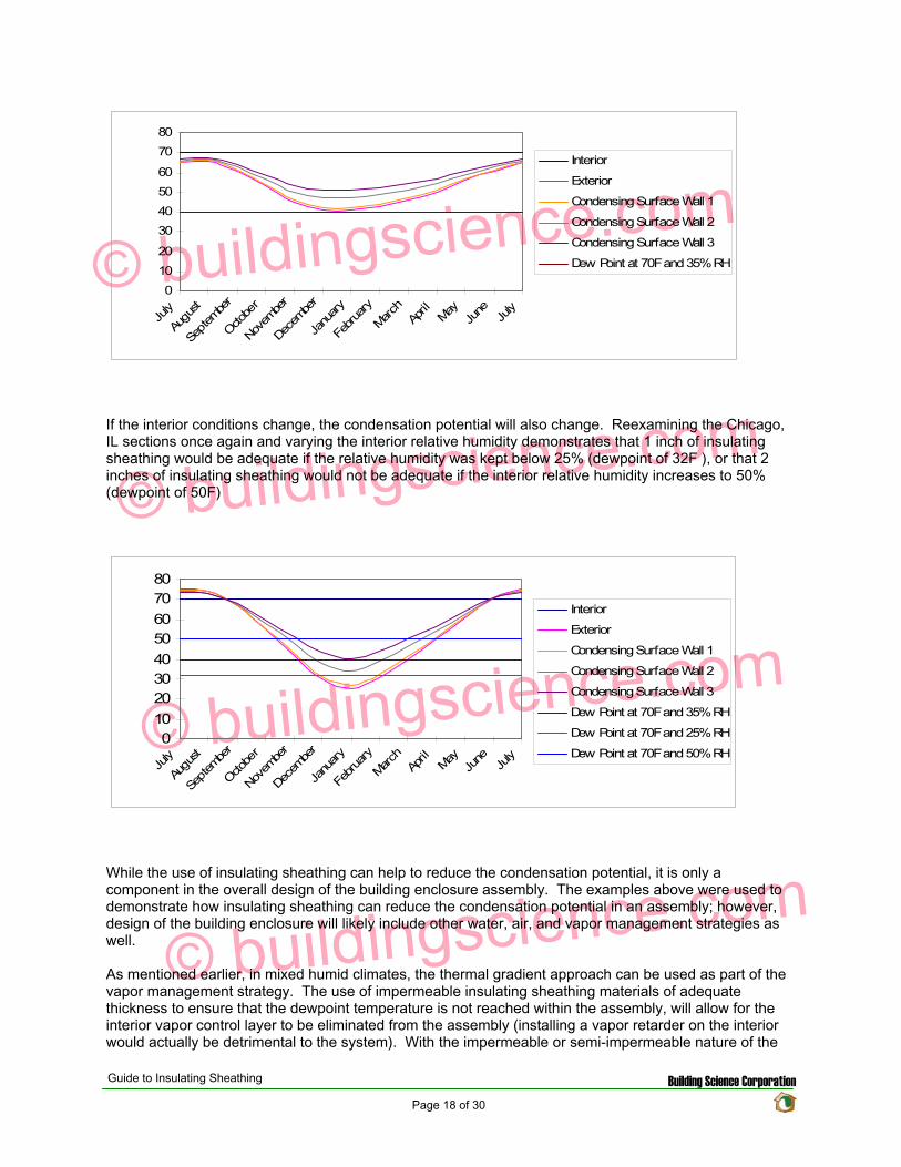
copy buildingsciencecom
copy buildingsciencecom
copy buildingsciencecom
copy buildingsciencecom
0
10
20
30
40
50
60
70
80
July
Augu
st
Septem
ber
Octo
ber
Novem
ber
Decem
ber
Janu
ary
Februa
ry
March
April
May
June
Ju
ly
Interior
Exterior
Condensing Surface Wall 1
Condensing Surface Wall 2
Condensing Surface Wall 3
Dew Point at 70F and 35 RH
If the interior conditions change the condensation potential will also change Reexamining the Chicago IL sections once again and varying the interior relative humidity demonstrates that 1 inch of insulating sheathing would be adequate if the relative humidity was kept below 25 (dewpoint of 32F ) or that 2 inches of insulating sheathing would not be adequate if the interior relative humidity increases to 50 (dewpoint of 50F)
0 10
20 30 40
50 60
70 80
July
Augu
st
Septem
ber
Octo
ber
Novem
ber
Decem
ber
Janu
ary
Februa
ry
March
April
May
June
Ju
ly
Interior
Exterior
Condensing Surface Wall 1
Condensing Surface Wall 2
Condensing Surface Wall 3
Dew Point at 70F and 35 RH
Dew Point at 70F and 25 RH
Dew Point at 70F and 50 RH
While the use of insulating sheathing can help to reduce the condensation potential it is only a component in the overall design of the building enclosure assembly The examples above were used to demonstrate how insulating sheathing can reduce the condensation potential in an assembly however design of the building enclosure will likely include other water air and vapor management strategies as well
As mentioned earlier in mixed humid climates the thermal gradient approach can be used as part of the vapor management strategy The use of impermeable insulating sheathing materials of adequate thickness to ensure that the dewpoint temperature is not reached within the assembly will allow for the interior vapor control layer to be eliminated from the assembly (installing a vapor retarder on the interior would actually be detrimental to the system) With the impermeable or semi-impermeable nature of the
Guide to Insulating Sheathing Building Science Corporation Page 18 of 30
sheathing the exterior face of the board would function as a vapor retarder during the cooling month while the interior face of the insulating sheathing would function as a vapor retarder in the heating months The air barrier for the system could also be installed to the interior or exterior of the assembly This approach should also be combined with a slight positive interior pressure to limit the amount of infiltration of moist air during the cooling season as well as some interior moisture control to ensure that the interior RH does not exceed the maximum levels to prevent condensation on the interior surface of the exterior sheathing during the heating season
copy buildingsciencecom
copy buildingsciencecom
copy buildingsciencecom
copy buildingsciencecom
Guide to Insulating Sheathing Building Science Corporation Page 19 of 30
Design and Construction
The following four wall sections are used as the basis for discussion for this section
copy buildingsciencecom
copy buildingsciencecom
copy buildingsciencecom
copy buildingsciencecom
General Installation
Insulating sheathing should be installed based on manufacturerrsquos recommendations for fastener type and amount It is recommended to layout the insulating sheathing such that vertical joints do not occur at the corners of window and door openings or over window heads if possible
In Wall Section 1 and Wall Section 2 the primary drainage plane occurs behind the insulating sheathing All water management details (flashing and window installation details) should be tied back to the plane of the housewrap In these configurations while the insulating sheathing is not officially considered to be part of the drainage system of the wall it will provide some protection for the housewrap in preventing much of the exterior rain water that penetrates past the cladding from penetrating through to the actual drainage plane
For Wall Section 3 the primary drainage plane to the exterior of the insulating sheathing and more exposed to the elements In this configuration the water management and window installation details are integrated into the housewrap at the exterior face of the insulating sheathing Water management details would be the same as normal details of recommended good practice for wood sheathed house design
Wall Section 4 requires some special detailing All the joints between the insulation boards must be designed in such a way as to prevent water from penetrating past the exterior face of the insulation Sealing or taping the vertical joints should be done and if possible products that use shingle lapped or tongue and groove joints should be used A polyethylene flashing is recommended to be installed at the horizontal joints in the system
Guide to Insulating Sheathing Building Science Corporation Page 20 of 30
In order for the insulation sheathing to be used as a water resistive barrier the vertical plane of the exterior face of the sheathing must be as continuous as possible This is to prevent locations within the wall assembly where drainage could be blocked or where water might be held
copy buildingsciencecom
copy buildingsciencecom
copy buildingsciencecom
copy buildingsciencecom
For added protecting window head flashing and roof step flashings can be easily regletted into the face of the foam sheathing providing for better protection against flashing failure and reverse flashing problems The reglette should only penetrate into the face of the sheathing and not all the way through the sheathing
Cladding Attachment
For siding systems (wood vinyl and fiber cement) and masonry veneers there is virtually no change from standard recommended practice for cladding attachment details One of the only differences is that all fasteners must be installed through to the studs as insulating sheathing does not have adequate structural capacity both in shear and pull out strength
For Wall Section 1 and Wall Section 2 cladding systems such as traditional hard coat stucco (including thin brick and manufactured stone veneer) and acrylic stucco can be directly applied to the insulation board With these types of systems it is recommended to use drained insulation boards (ones with vertical grooves cut in the back) or to use a vertically textured (or profiled) housewrap to ensure that there is a drainage space behind the rigid board
For Wall Section 3 and Wall Section 4 traditional hard coat stucco (including thin brick and manufactured stone veneer) should NOT be installed without the addition of at least one layer of building paper or house wrap between the stucco renderings and the housewrap or drainage plane sheathing to act as a bond break
Roof Connection
Popular roof construction types will vary from one region to another Much of the country relies on sloped roof assemblies with eave overhangs In other areas flat roof construction is more common The roof wall connection will vary therefore depending on the type of roof assembly used
In sloped roof applications the insulating sheathing is installed up to the underside of the roof truss If desired the insulating sheathing can be notched around the roof trusses to act as a wind shield for the attic insulation
For Wall Section 1 and Wall Section 2 at gable ends and parapets the insulating sheathing is not required to extend to the full height of the construction since the drainage plane is maintained behind the insulation through the use of a housewrap Due to this the insulating sheathing can be stopped at the top of the plane of attic insulation However it may be convenient to extend the insulating sheathing the full height to simplify the cladding attachment at these areas Otherwise alternative methods to fur out and support the cladding will be required
Conversely For Wall Section 3 and Wall Section 4 the continuity of the drainage plane must be maintained to the exterior of the insulating sheathing For these wall sections often the simplest way to maintain the continuity of the drainage plane is to install the insulating sheathing up to the top of the parapet or over the gable end An alternative method for maintaining the drainage plane is to use a thin profile structural sheathing furred out and installed so that it is in plane or proud of the insulating sheathing to maintain the continuity of the drainage plane
Guide to Insulating Sheathing Building Science Corporation Page 21 of 30
copy buildingsciencecom
copy buildingsciencecom
copy buildingsciencecom
copy buildingsciencecom
Foundations Connection
The installation details for insulating sheathing at foundations are generally the same for all foundation types The intention is to continue the sheathing past the top edge of the foundation or basement wall to create a shingle lap with the foundation For walls with brick veneer this may not be possible In this situation a seat should be cast into the top of the foundation wall so that the brick and the insulation sheathing terminate at a level below the bottom plate of the stud wall This will allow a shingle lap joint to be created
Guide to Insulating Sheathing Building Science Corporation Page 22 of 30
copy buildingsciencecom
copy buildingsciencecom
copy buildingsciencecom
copy buildingsciencecom
Guide to Insulating Sheathing Building Science Corporation Page 23 of 30
Window installation
The following window installation sequence details is applicable to Wall Section 1 (Wall Section 2 details would be almost identical ndash with the elimination of wood sheathing behind the housewrap)
copy buildingsciencecom
copy buildingsciencecom
copy buildingsciencecom
copy buildingsciencecom
1 Wood frame wall with OSB and housewrap 2 Modified ldquoIrdquo cut in housewrap 3 Housewrap folded in at jambs and sill Housewrap at head temporarily folded up or alternatively
tucked under Install backdam
4 Install adhesive backed sill flashing and corner flashing patches at sill 5 Apply sealant at jambs head and sill Alternatively sealant can be applied to the back side of the
nailing flange (sealants housewraps and flashings must be chemically compatible) 6 Install window plumb level and square as per manufacturerrsquos instructions
Guide to Insulating Sheathing Building Science Corporation Page 24 of 30
copy buildingsciencecom
copy buildingsciencecom
copy buildingsciencecom
copy buildingsciencecom
7 Install jamb flashing first Install a drip cap (if applicable) Install head flashing 8 Fold down head housewrap 9 Apply corner patches at head Air seal window around the entire perimeter on the interior with
sealant or non-expanding foam Install foam sheathing over housewrap
Guide to Insulating Sheathing Building Science Corporation Page 25 of 30
The following window installation sequence details are applicable to Wall Section 4 (Wall Section 3 details would be almost identical ndash addition of housewrap to the exterior of the insulating sheathing prior to window rough opening preparation)
copy buildingsciencecom
copy buildingsciencecom
copy buildingsciencecom
copy buildingsciencecom
1 Install foam sheathing on wood frame wall 2 Install backdam 3 Install first piece of adhesive backed sill flashing apply second piece of adhesive backed sill
flashing
4 Install corner flashing patches at sill 5 Install adhesive backed jamb flashings (jamb flashing adhered to foam and stapled to frame) 6 Apply sealant at jambs head and sill Alternatively sealant can be applied to the back side of the
nailing flange (sealants housewraps and flashings must be chemically compatible)
Guide to Insulating Sheathing Building Science Corporation Page 26 of 30
copy buildingsciencecom
copy buildingsciencecom
copy buildingsciencecom
copy buildingsciencecom
7 Install window plumb level and square as per manufacturerrsquos instructions 8 Install jamb flashing 9 Install drip cap (if applicable) install head flashing tape head flashing air seal around the
perimeter on the interior with sealant or low expanding foam
Guide to Insulating Sheathing Building Science Corporation Page 27 of 30
copy buildingsciencecom
copy buildingsciencecom
copy buildingsciencecom
copy buildingsciencecom
Related Concepts
Advanced Framing
The use of advanced framing with insulation sheathing is another concept used to reduce the amount of materials in residential construction The layout of the sheathing boards over the area of the wall framing should be done to minimize the amount of cutting of the material and construction waste created
wall
Single top plate
studs by rim
Single
rough
support will be required under point
solid blocking
Two stud corners
No headers in non-bearing
stud at
opening
No cripples under window opening
Header hangers instead of jack studs (see Figure 55)
Roof framingtrusses line up with wall
and floor framing
Insulated header
Single top plate
Point load transferred between
closure material acting as header If rim closure material is non-structural
loads Use
between joists
This will impact the effective thermal resistance of the wall assembly as well Standard residential construction will end up with a framing fraction for the wall assemblies of around 23 of the wall area With advanced framing this fraction can be reduced down to approximately 16 and sometimes even less If we reexamine the techniques for calculating the effective R-value of the assembly as used in the Thermal Resistance section we obtain the following results
Guide to Insulating Sheathing Building Science Corporation Page 28 of 30
copy buildingsciencecom
copy buildingsciencecom
copy buildingsciencecom
copy buildingsciencecom
Element
Cavity Section R-value
Stud Section R-value
Outside Air Film 017 017 1 Rigid Insulation 5 5 2x6 Wood Stud na 583 55 Fiberglass Batt 19 na 12 Interior Gypsum 045 045 Interior Air Film 068 068 Total 253 1213
The effective R-value of the following assembly with a 16 framing fraction is
R(cavity) = 1[(08419)+(016583)] R(cavity) = 1396
R(total) = 017+062+1396+045+068 R(total) = 2026
The same effective R-value with a 23 framing fraction yielded a total R-value of 1880 This represents a 78 increase in thermal resistance for the entire assembly
Cross Bracing and Inset Shear Panels
In Wall Sections 2 3 and 4 the regular method for shear resistance has been removed from the assembly (traditionally wood sheathing over the exterior of the building) Due to this alternative methods for providing shear resistance must be incorporated into the design
A common approach is to install exterior structural wood sheathing at the corners and at regular intervals as needed to provide for the lateral load resistance requirements for the location (wind and seismic) Installing the structural wood sheathing to exterior interferes with the installation of the insulating sheathing This can create problems with drainage plane continuity and thermal bridging (due to the reduction in insulation thickness)
The recommendation is to use systems and techniques that can be installed flush with the exterior face of the wood studs This way the insulation can be installed in a continuous uniform thickness over the entire exterior wall area Some of the methods to achieve this are through the use of metal cross bracing or inset shear panels
Guide to Insulating Sheathing Building Science Corporation Page 29 of 30
With metal cross bracing the thickness of the metal braces are insignificant and do not interfere with the installation of the insulating sheathing The capacity of the metal cross bracing however may not be adequate for areas with high wind loads andor seismic activity In these locations a more robust form of lateral load resistance may be needed
copy buildingsciencecom
copy buildingsciencecom
copy buildingsciencecom
copy buildingsciencecom
Inset shear panels can provide for high levels of lateral load resistance and can be used in all wind and seismic zones Inset shear panels are wood framed panels that fit within the stud spacing of the wall assembly In this way the exterior face of the panel is flush with the exterior face of the wood studs
Depending on the area of the country different requirements for wind and seismic resistance are required The method chosen will depend on the individual code requirements for the area
Guide to Insulating Sheathing Building Science Corporation Page 30 of 30
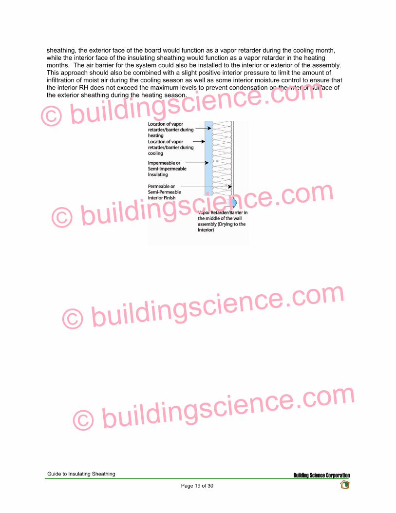
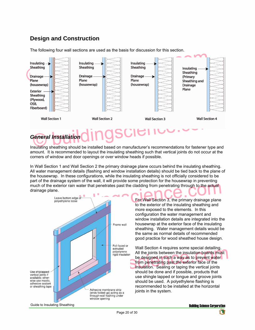
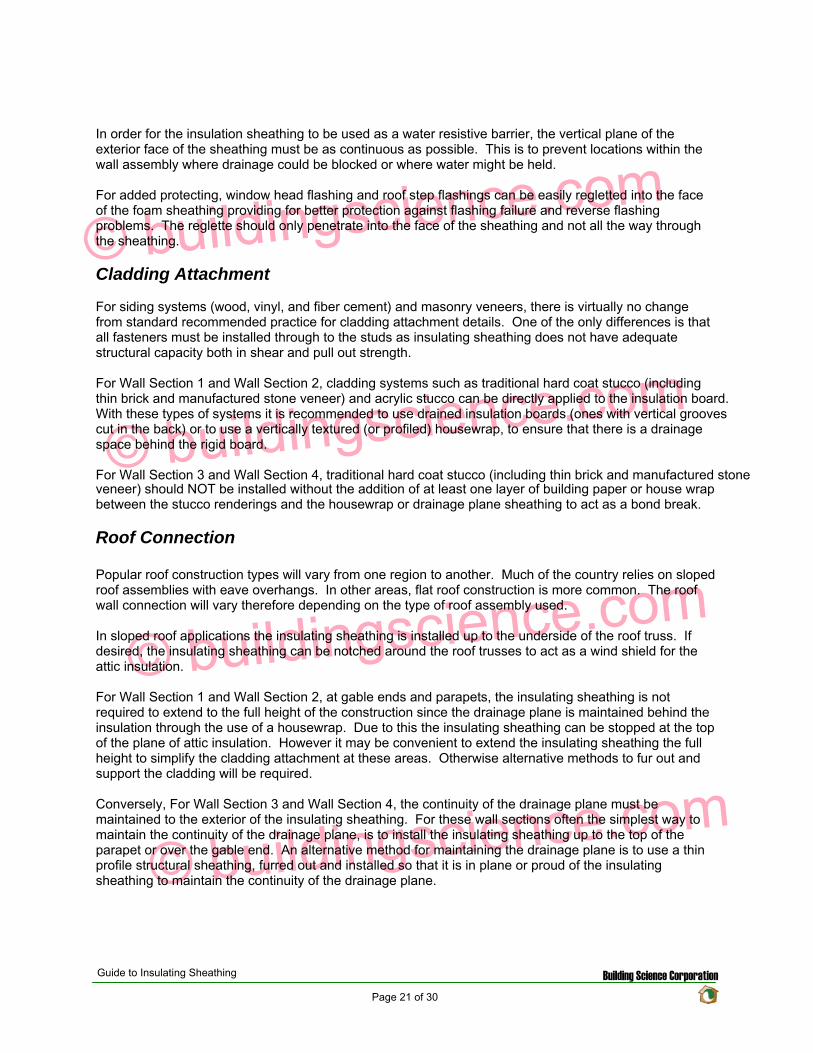
copy buildingsciencecom
copy buildingsciencecom
copy buildingsciencecom
copy buildingsciencecom
Foundations Connection
The installation details for insulating sheathing at foundations are generally the same for all foundation types The intention is to continue the sheathing past the top edge of the foundation or basement wall to create a shingle lap with the foundation For walls with brick veneer this may not be possible In this situation a seat should be cast into the top of the foundation wall so that the brick and the insulation sheathing terminate at a level below the bottom plate of the stud wall This will allow a shingle lap joint to be created
Guide to Insulating Sheathing Building Science Corporation Page 22 of 30
copy buildingsciencecom
copy buildingsciencecom
copy buildingsciencecom
copy buildingsciencecom
Guide to Insulating Sheathing Building Science Corporation Page 23 of 30
Window installation
The following window installation sequence details is applicable to Wall Section 1 (Wall Section 2 details would be almost identical ndash with the elimination of wood sheathing behind the housewrap)
copy buildingsciencecom
copy buildingsciencecom
copy buildingsciencecom
copy buildingsciencecom
1 Wood frame wall with OSB and housewrap 2 Modified ldquoIrdquo cut in housewrap 3 Housewrap folded in at jambs and sill Housewrap at head temporarily folded up or alternatively
tucked under Install backdam
4 Install adhesive backed sill flashing and corner flashing patches at sill 5 Apply sealant at jambs head and sill Alternatively sealant can be applied to the back side of the
nailing flange (sealants housewraps and flashings must be chemically compatible) 6 Install window plumb level and square as per manufacturerrsquos instructions
Guide to Insulating Sheathing Building Science Corporation Page 24 of 30
copy buildingsciencecom
copy buildingsciencecom
copy buildingsciencecom
copy buildingsciencecom
7 Install jamb flashing first Install a drip cap (if applicable) Install head flashing 8 Fold down head housewrap 9 Apply corner patches at head Air seal window around the entire perimeter on the interior with
sealant or non-expanding foam Install foam sheathing over housewrap
Guide to Insulating Sheathing Building Science Corporation Page 25 of 30
The following window installation sequence details are applicable to Wall Section 4 (Wall Section 3 details would be almost identical ndash addition of housewrap to the exterior of the insulating sheathing prior to window rough opening preparation)
copy buildingsciencecom
copy buildingsciencecom
copy buildingsciencecom
copy buildingsciencecom
1 Install foam sheathing on wood frame wall 2 Install backdam 3 Install first piece of adhesive backed sill flashing apply second piece of adhesive backed sill
flashing
4 Install corner flashing patches at sill 5 Install adhesive backed jamb flashings (jamb flashing adhered to foam and stapled to frame) 6 Apply sealant at jambs head and sill Alternatively sealant can be applied to the back side of the
nailing flange (sealants housewraps and flashings must be chemically compatible)
Guide to Insulating Sheathing Building Science Corporation Page 26 of 30
copy buildingsciencecom
copy buildingsciencecom
copy buildingsciencecom
copy buildingsciencecom
7 Install window plumb level and square as per manufacturerrsquos instructions 8 Install jamb flashing 9 Install drip cap (if applicable) install head flashing tape head flashing air seal around the
perimeter on the interior with sealant or low expanding foam
Guide to Insulating Sheathing Building Science Corporation Page 27 of 30
copy buildingsciencecom
copy buildingsciencecom
copy buildingsciencecom
copy buildingsciencecom
Related Concepts
Advanced Framing
The use of advanced framing with insulation sheathing is another concept used to reduce the amount of materials in residential construction The layout of the sheathing boards over the area of the wall framing should be done to minimize the amount of cutting of the material and construction waste created
wall
Single top plate
studs by rim
Single
rough
support will be required under point
solid blocking
Two stud corners
No headers in non-bearing
stud at
opening
No cripples under window opening
Header hangers instead of jack studs (see Figure 55)
Roof framingtrusses line up with wall
and floor framing
Insulated header
Single top plate
Point load transferred between
closure material acting as header If rim closure material is non-structural
loads Use
between joists
This will impact the effective thermal resistance of the wall assembly as well Standard residential construction will end up with a framing fraction for the wall assemblies of around 23 of the wall area With advanced framing this fraction can be reduced down to approximately 16 and sometimes even less If we reexamine the techniques for calculating the effective R-value of the assembly as used in the Thermal Resistance section we obtain the following results
Guide to Insulating Sheathing Building Science Corporation Page 28 of 30
copy buildingsciencecom
copy buildingsciencecom
copy buildingsciencecom
copy buildingsciencecom
Element
Cavity Section R-value
Stud Section R-value
Outside Air Film 017 017 1 Rigid Insulation 5 5 2x6 Wood Stud na 583 55 Fiberglass Batt 19 na 12 Interior Gypsum 045 045 Interior Air Film 068 068 Total 253 1213
The effective R-value of the following assembly with a 16 framing fraction is
R(cavity) = 1[(08419)+(016583)] R(cavity) = 1396
R(total) = 017+062+1396+045+068 R(total) = 2026
The same effective R-value with a 23 framing fraction yielded a total R-value of 1880 This represents a 78 increase in thermal resistance for the entire assembly
Cross Bracing and Inset Shear Panels
In Wall Sections 2 3 and 4 the regular method for shear resistance has been removed from the assembly (traditionally wood sheathing over the exterior of the building) Due to this alternative methods for providing shear resistance must be incorporated into the design
A common approach is to install exterior structural wood sheathing at the corners and at regular intervals as needed to provide for the lateral load resistance requirements for the location (wind and seismic) Installing the structural wood sheathing to exterior interferes with the installation of the insulating sheathing This can create problems with drainage plane continuity and thermal bridging (due to the reduction in insulation thickness)
The recommendation is to use systems and techniques that can be installed flush with the exterior face of the wood studs This way the insulation can be installed in a continuous uniform thickness over the entire exterior wall area Some of the methods to achieve this are through the use of metal cross bracing or inset shear panels
Guide to Insulating Sheathing Building Science Corporation Page 29 of 30
With metal cross bracing the thickness of the metal braces are insignificant and do not interfere with the installation of the insulating sheathing The capacity of the metal cross bracing however may not be adequate for areas with high wind loads andor seismic activity In these locations a more robust form of lateral load resistance may be needed
copy buildingsciencecom
copy buildingsciencecom
copy buildingsciencecom
copy buildingsciencecom
Inset shear panels can provide for high levels of lateral load resistance and can be used in all wind and seismic zones Inset shear panels are wood framed panels that fit within the stud spacing of the wall assembly In this way the exterior face of the panel is flush with the exterior face of the wood studs
Depending on the area of the country different requirements for wind and seismic resistance are required The method chosen will depend on the individual code requirements for the area
Guide to Insulating Sheathing Building Science Corporation Page 30 of 30
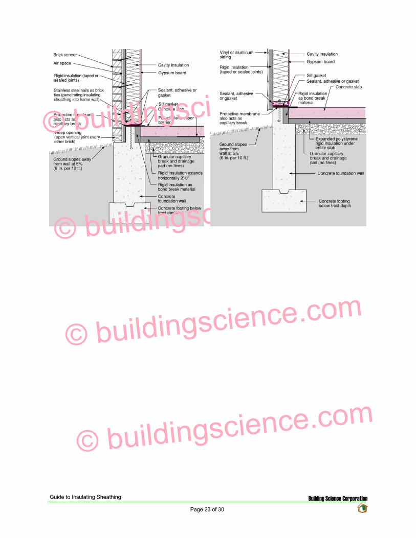
copy buildingsciencecom
copy buildingsciencecom
copy buildingsciencecom
copy buildingsciencecom
Guide to Insulating Sheathing Building Science Corporation Page 23 of 30
Window installation
The following window installation sequence details is applicable to Wall Section 1 (Wall Section 2 details would be almost identical ndash with the elimination of wood sheathing behind the housewrap)
copy buildingsciencecom
copy buildingsciencecom
copy buildingsciencecom
copy buildingsciencecom
1 Wood frame wall with OSB and housewrap 2 Modified ldquoIrdquo cut in housewrap 3 Housewrap folded in at jambs and sill Housewrap at head temporarily folded up or alternatively
tucked under Install backdam
4 Install adhesive backed sill flashing and corner flashing patches at sill 5 Apply sealant at jambs head and sill Alternatively sealant can be applied to the back side of the
nailing flange (sealants housewraps and flashings must be chemically compatible) 6 Install window plumb level and square as per manufacturerrsquos instructions
Guide to Insulating Sheathing Building Science Corporation Page 24 of 30
copy buildingsciencecom
copy buildingsciencecom
copy buildingsciencecom
copy buildingsciencecom
7 Install jamb flashing first Install a drip cap (if applicable) Install head flashing 8 Fold down head housewrap 9 Apply corner patches at head Air seal window around the entire perimeter on the interior with
sealant or non-expanding foam Install foam sheathing over housewrap
Guide to Insulating Sheathing Building Science Corporation Page 25 of 30
The following window installation sequence details are applicable to Wall Section 4 (Wall Section 3 details would be almost identical ndash addition of housewrap to the exterior of the insulating sheathing prior to window rough opening preparation)
copy buildingsciencecom
copy buildingsciencecom
copy buildingsciencecom
copy buildingsciencecom
1 Install foam sheathing on wood frame wall 2 Install backdam 3 Install first piece of adhesive backed sill flashing apply second piece of adhesive backed sill
flashing
4 Install corner flashing patches at sill 5 Install adhesive backed jamb flashings (jamb flashing adhered to foam and stapled to frame) 6 Apply sealant at jambs head and sill Alternatively sealant can be applied to the back side of the
nailing flange (sealants housewraps and flashings must be chemically compatible)
Guide to Insulating Sheathing Building Science Corporation Page 26 of 30
copy buildingsciencecom
copy buildingsciencecom
copy buildingsciencecom
copy buildingsciencecom
7 Install window plumb level and square as per manufacturerrsquos instructions 8 Install jamb flashing 9 Install drip cap (if applicable) install head flashing tape head flashing air seal around the
perimeter on the interior with sealant or low expanding foam
Guide to Insulating Sheathing Building Science Corporation Page 27 of 30
copy buildingsciencecom
copy buildingsciencecom
copy buildingsciencecom
copy buildingsciencecom
Related Concepts
Advanced Framing
The use of advanced framing with insulation sheathing is another concept used to reduce the amount of materials in residential construction The layout of the sheathing boards over the area of the wall framing should be done to minimize the amount of cutting of the material and construction waste created
wall
Single top plate
studs by rim
Single
rough
support will be required under point
solid blocking
Two stud corners
No headers in non-bearing
stud at
opening
No cripples under window opening
Header hangers instead of jack studs (see Figure 55)
Roof framingtrusses line up with wall
and floor framing
Insulated header
Single top plate
Point load transferred between
closure material acting as header If rim closure material is non-structural
loads Use
between joists
This will impact the effective thermal resistance of the wall assembly as well Standard residential construction will end up with a framing fraction for the wall assemblies of around 23 of the wall area With advanced framing this fraction can be reduced down to approximately 16 and sometimes even less If we reexamine the techniques for calculating the effective R-value of the assembly as used in the Thermal Resistance section we obtain the following results
Guide to Insulating Sheathing Building Science Corporation Page 28 of 30
copy buildingsciencecom
copy buildingsciencecom
copy buildingsciencecom
copy buildingsciencecom
Element
Cavity Section R-value
Stud Section R-value
Outside Air Film 017 017 1 Rigid Insulation 5 5 2x6 Wood Stud na 583 55 Fiberglass Batt 19 na 12 Interior Gypsum 045 045 Interior Air Film 068 068 Total 253 1213
The effective R-value of the following assembly with a 16 framing fraction is
R(cavity) = 1[(08419)+(016583)] R(cavity) = 1396
R(total) = 017+062+1396+045+068 R(total) = 2026
The same effective R-value with a 23 framing fraction yielded a total R-value of 1880 This represents a 78 increase in thermal resistance for the entire assembly
Cross Bracing and Inset Shear Panels
In Wall Sections 2 3 and 4 the regular method for shear resistance has been removed from the assembly (traditionally wood sheathing over the exterior of the building) Due to this alternative methods for providing shear resistance must be incorporated into the design
A common approach is to install exterior structural wood sheathing at the corners and at regular intervals as needed to provide for the lateral load resistance requirements for the location (wind and seismic) Installing the structural wood sheathing to exterior interferes with the installation of the insulating sheathing This can create problems with drainage plane continuity and thermal bridging (due to the reduction in insulation thickness)
The recommendation is to use systems and techniques that can be installed flush with the exterior face of the wood studs This way the insulation can be installed in a continuous uniform thickness over the entire exterior wall area Some of the methods to achieve this are through the use of metal cross bracing or inset shear panels
Guide to Insulating Sheathing Building Science Corporation Page 29 of 30
With metal cross bracing the thickness of the metal braces are insignificant and do not interfere with the installation of the insulating sheathing The capacity of the metal cross bracing however may not be adequate for areas with high wind loads andor seismic activity In these locations a more robust form of lateral load resistance may be needed
copy buildingsciencecom
copy buildingsciencecom
copy buildingsciencecom
copy buildingsciencecom
Inset shear panels can provide for high levels of lateral load resistance and can be used in all wind and seismic zones Inset shear panels are wood framed panels that fit within the stud spacing of the wall assembly In this way the exterior face of the panel is flush with the exterior face of the wood studs
Depending on the area of the country different requirements for wind and seismic resistance are required The method chosen will depend on the individual code requirements for the area
Guide to Insulating Sheathing Building Science Corporation Page 30 of 30
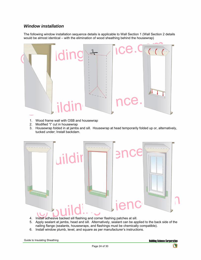
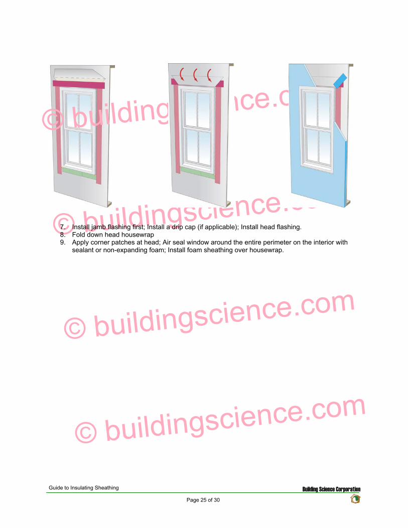
copy buildingsciencecom
copy buildingsciencecom
copy buildingsciencecom
copy buildingsciencecom
7 Install jamb flashing first Install a drip cap (if applicable) Install head flashing 8 Fold down head housewrap 9 Apply corner patches at head Air seal window around the entire perimeter on the interior with
sealant or non-expanding foam Install foam sheathing over housewrap
Guide to Insulating Sheathing Building Science Corporation Page 25 of 30
The following window installation sequence details are applicable to Wall Section 4 (Wall Section 3 details would be almost identical ndash addition of housewrap to the exterior of the insulating sheathing prior to window rough opening preparation)
copy buildingsciencecom
copy buildingsciencecom
copy buildingsciencecom
copy buildingsciencecom
1 Install foam sheathing on wood frame wall 2 Install backdam 3 Install first piece of adhesive backed sill flashing apply second piece of adhesive backed sill
flashing
4 Install corner flashing patches at sill 5 Install adhesive backed jamb flashings (jamb flashing adhered to foam and stapled to frame) 6 Apply sealant at jambs head and sill Alternatively sealant can be applied to the back side of the
nailing flange (sealants housewraps and flashings must be chemically compatible)
Guide to Insulating Sheathing Building Science Corporation Page 26 of 30
copy buildingsciencecom
copy buildingsciencecom
copy buildingsciencecom
copy buildingsciencecom
7 Install window plumb level and square as per manufacturerrsquos instructions 8 Install jamb flashing 9 Install drip cap (if applicable) install head flashing tape head flashing air seal around the
perimeter on the interior with sealant or low expanding foam
Guide to Insulating Sheathing Building Science Corporation Page 27 of 30
copy buildingsciencecom
copy buildingsciencecom
copy buildingsciencecom
copy buildingsciencecom
Related Concepts
Advanced Framing
The use of advanced framing with insulation sheathing is another concept used to reduce the amount of materials in residential construction The layout of the sheathing boards over the area of the wall framing should be done to minimize the amount of cutting of the material and construction waste created
wall
Single top plate
studs by rim
Single
rough
support will be required under point
solid blocking
Two stud corners
No headers in non-bearing
stud at
opening
No cripples under window opening
Header hangers instead of jack studs (see Figure 55)
Roof framingtrusses line up with wall
and floor framing
Insulated header
Single top plate
Point load transferred between
closure material acting as header If rim closure material is non-structural
loads Use
between joists
This will impact the effective thermal resistance of the wall assembly as well Standard residential construction will end up with a framing fraction for the wall assemblies of around 23 of the wall area With advanced framing this fraction can be reduced down to approximately 16 and sometimes even less If we reexamine the techniques for calculating the effective R-value of the assembly as used in the Thermal Resistance section we obtain the following results
Guide to Insulating Sheathing Building Science Corporation Page 28 of 30
copy buildingsciencecom
copy buildingsciencecom
copy buildingsciencecom
copy buildingsciencecom
Element
Cavity Section R-value
Stud Section R-value
Outside Air Film 017 017 1 Rigid Insulation 5 5 2x6 Wood Stud na 583 55 Fiberglass Batt 19 na 12 Interior Gypsum 045 045 Interior Air Film 068 068 Total 253 1213
The effective R-value of the following assembly with a 16 framing fraction is
R(cavity) = 1[(08419)+(016583)] R(cavity) = 1396
R(total) = 017+062+1396+045+068 R(total) = 2026
The same effective R-value with a 23 framing fraction yielded a total R-value of 1880 This represents a 78 increase in thermal resistance for the entire assembly
Cross Bracing and Inset Shear Panels
In Wall Sections 2 3 and 4 the regular method for shear resistance has been removed from the assembly (traditionally wood sheathing over the exterior of the building) Due to this alternative methods for providing shear resistance must be incorporated into the design
A common approach is to install exterior structural wood sheathing at the corners and at regular intervals as needed to provide for the lateral load resistance requirements for the location (wind and seismic) Installing the structural wood sheathing to exterior interferes with the installation of the insulating sheathing This can create problems with drainage plane continuity and thermal bridging (due to the reduction in insulation thickness)
The recommendation is to use systems and techniques that can be installed flush with the exterior face of the wood studs This way the insulation can be installed in a continuous uniform thickness over the entire exterior wall area Some of the methods to achieve this are through the use of metal cross bracing or inset shear panels
Guide to Insulating Sheathing Building Science Corporation Page 29 of 30
With metal cross bracing the thickness of the metal braces are insignificant and do not interfere with the installation of the insulating sheathing The capacity of the metal cross bracing however may not be adequate for areas with high wind loads andor seismic activity In these locations a more robust form of lateral load resistance may be needed
copy buildingsciencecom
copy buildingsciencecom
copy buildingsciencecom
copy buildingsciencecom
Inset shear panels can provide for high levels of lateral load resistance and can be used in all wind and seismic zones Inset shear panels are wood framed panels that fit within the stud spacing of the wall assembly In this way the exterior face of the panel is flush with the exterior face of the wood studs
Depending on the area of the country different requirements for wind and seismic resistance are required The method chosen will depend on the individual code requirements for the area
Guide to Insulating Sheathing Building Science Corporation Page 30 of 30
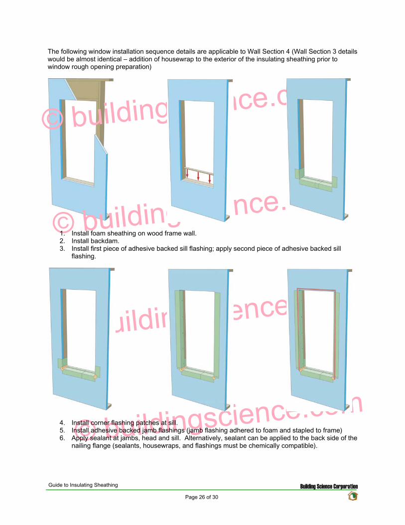
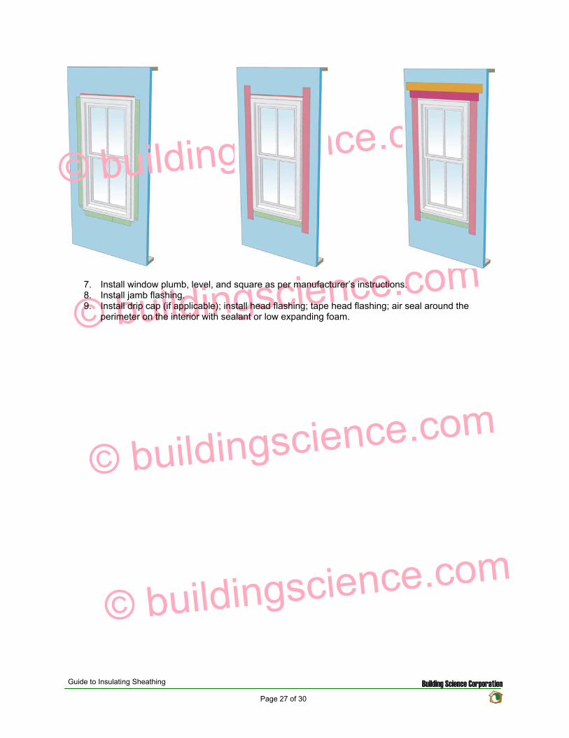
copy buildingsciencecom
copy buildingsciencecom
copy buildingsciencecom
copy buildingsciencecom
7 Install window plumb level and square as per manufacturerrsquos instructions 8 Install jamb flashing 9 Install drip cap (if applicable) install head flashing tape head flashing air seal around the
perimeter on the interior with sealant or low expanding foam
Guide to Insulating Sheathing Building Science Corporation Page 27 of 30
copy buildingsciencecom
copy buildingsciencecom
copy buildingsciencecom
copy buildingsciencecom
Related Concepts
Advanced Framing
The use of advanced framing with insulation sheathing is another concept used to reduce the amount of materials in residential construction The layout of the sheathing boards over the area of the wall framing should be done to minimize the amount of cutting of the material and construction waste created
wall
Single top plate
studs by rim
Single
rough
support will be required under point
solid blocking
Two stud corners
No headers in non-bearing
stud at
opening
No cripples under window opening
Header hangers instead of jack studs (see Figure 55)
Roof framingtrusses line up with wall
and floor framing
Insulated header
Single top plate
Point load transferred between
closure material acting as header If rim closure material is non-structural
loads Use
between joists
This will impact the effective thermal resistance of the wall assembly as well Standard residential construction will end up with a framing fraction for the wall assemblies of around 23 of the wall area With advanced framing this fraction can be reduced down to approximately 16 and sometimes even less If we reexamine the techniques for calculating the effective R-value of the assembly as used in the Thermal Resistance section we obtain the following results
Guide to Insulating Sheathing Building Science Corporation Page 28 of 30
copy buildingsciencecom
copy buildingsciencecom
copy buildingsciencecom
copy buildingsciencecom
Element
Cavity Section R-value
Stud Section R-value
Outside Air Film 017 017 1 Rigid Insulation 5 5 2x6 Wood Stud na 583 55 Fiberglass Batt 19 na 12 Interior Gypsum 045 045 Interior Air Film 068 068 Total 253 1213
The effective R-value of the following assembly with a 16 framing fraction is
R(cavity) = 1[(08419)+(016583)] R(cavity) = 1396
R(total) = 017+062+1396+045+068 R(total) = 2026
The same effective R-value with a 23 framing fraction yielded a total R-value of 1880 This represents a 78 increase in thermal resistance for the entire assembly
Cross Bracing and Inset Shear Panels
In Wall Sections 2 3 and 4 the regular method for shear resistance has been removed from the assembly (traditionally wood sheathing over the exterior of the building) Due to this alternative methods for providing shear resistance must be incorporated into the design
A common approach is to install exterior structural wood sheathing at the corners and at regular intervals as needed to provide for the lateral load resistance requirements for the location (wind and seismic) Installing the structural wood sheathing to exterior interferes with the installation of the insulating sheathing This can create problems with drainage plane continuity and thermal bridging (due to the reduction in insulation thickness)
The recommendation is to use systems and techniques that can be installed flush with the exterior face of the wood studs This way the insulation can be installed in a continuous uniform thickness over the entire exterior wall area Some of the methods to achieve this are through the use of metal cross bracing or inset shear panels
Guide to Insulating Sheathing Building Science Corporation Page 29 of 30
With metal cross bracing the thickness of the metal braces are insignificant and do not interfere with the installation of the insulating sheathing The capacity of the metal cross bracing however may not be adequate for areas with high wind loads andor seismic activity In these locations a more robust form of lateral load resistance may be needed
copy buildingsciencecom
copy buildingsciencecom
copy buildingsciencecom
copy buildingsciencecom
Inset shear panels can provide for high levels of lateral load resistance and can be used in all wind and seismic zones Inset shear panels are wood framed panels that fit within the stud spacing of the wall assembly In this way the exterior face of the panel is flush with the exterior face of the wood studs
Depending on the area of the country different requirements for wind and seismic resistance are required The method chosen will depend on the individual code requirements for the area
Guide to Insulating Sheathing Building Science Corporation Page 30 of 30
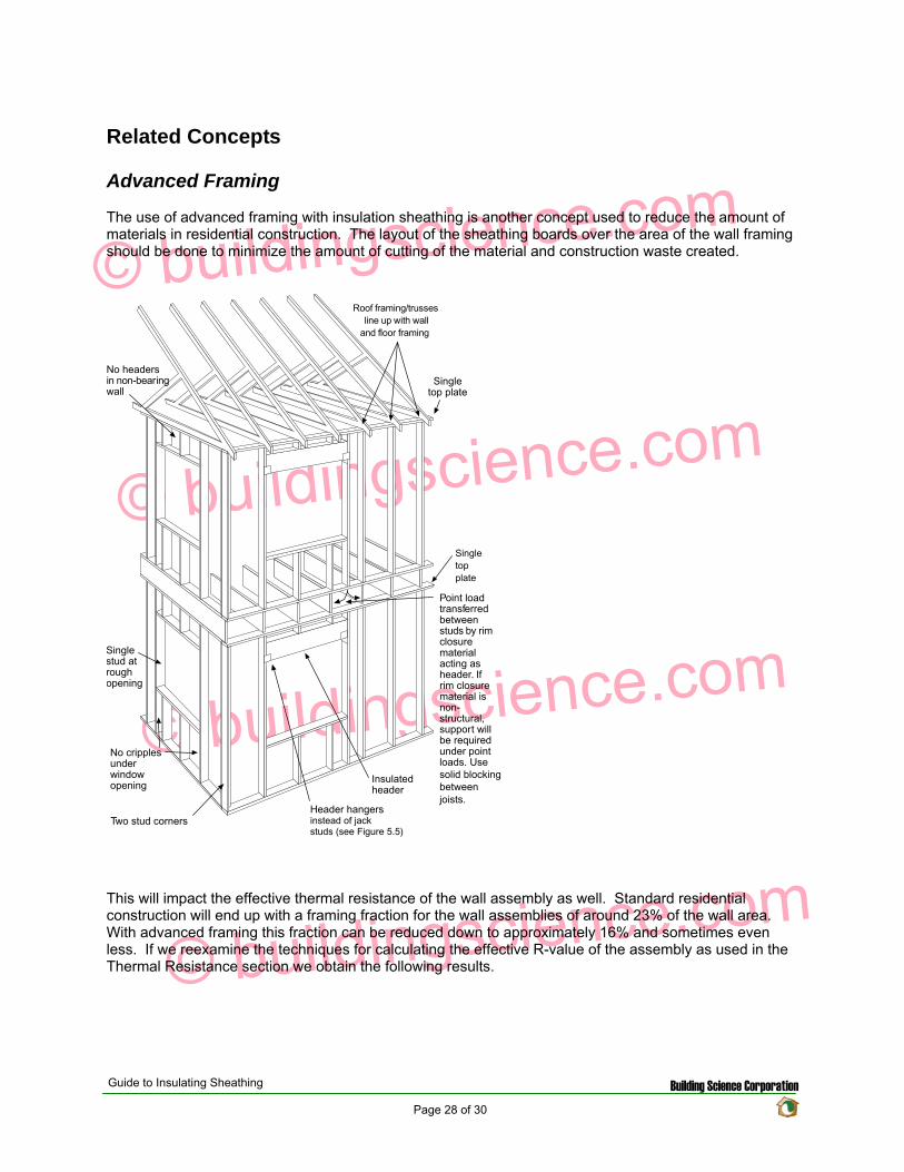
copy buildingsciencecom
copy buildingsciencecom
copy buildingsciencecom
copy buildingsciencecom
Related Concepts
Advanced Framing
The use of advanced framing with insulation sheathing is another concept used to reduce the amount of materials in residential construction The layout of the sheathing boards over the area of the wall framing should be done to minimize the amount of cutting of the material and construction waste created
wall
Single top plate
studs by rim
Single
rough
support will be required under point
solid blocking
Two stud corners
No headers in non-bearing
stud at
opening
No cripples under window opening
Header hangers instead of jack studs (see Figure 55)
Roof framingtrusses line up with wall
and floor framing
Insulated header
Single top plate
Point load transferred between
closure material acting as header If rim closure material is non-structural
loads Use
between joists
This will impact the effective thermal resistance of the wall assembly as well Standard residential construction will end up with a framing fraction for the wall assemblies of around 23 of the wall area With advanced framing this fraction can be reduced down to approximately 16 and sometimes even less If we reexamine the techniques for calculating the effective R-value of the assembly as used in the Thermal Resistance section we obtain the following results
Guide to Insulating Sheathing Building Science Corporation Page 28 of 30
copy buildingsciencecom
copy buildingsciencecom
copy buildingsciencecom
copy buildingsciencecom
Element
Cavity Section R-value
Stud Section R-value
Outside Air Film 017 017 1 Rigid Insulation 5 5 2x6 Wood Stud na 583 55 Fiberglass Batt 19 na 12 Interior Gypsum 045 045 Interior Air Film 068 068 Total 253 1213
The effective R-value of the following assembly with a 16 framing fraction is
R(cavity) = 1[(08419)+(016583)] R(cavity) = 1396
R(total) = 017+062+1396+045+068 R(total) = 2026
The same effective R-value with a 23 framing fraction yielded a total R-value of 1880 This represents a 78 increase in thermal resistance for the entire assembly
Cross Bracing and Inset Shear Panels
In Wall Sections 2 3 and 4 the regular method for shear resistance has been removed from the assembly (traditionally wood sheathing over the exterior of the building) Due to this alternative methods for providing shear resistance must be incorporated into the design
A common approach is to install exterior structural wood sheathing at the corners and at regular intervals as needed to provide for the lateral load resistance requirements for the location (wind and seismic) Installing the structural wood sheathing to exterior interferes with the installation of the insulating sheathing This can create problems with drainage plane continuity and thermal bridging (due to the reduction in insulation thickness)
The recommendation is to use systems and techniques that can be installed flush with the exterior face of the wood studs This way the insulation can be installed in a continuous uniform thickness over the entire exterior wall area Some of the methods to achieve this are through the use of metal cross bracing or inset shear panels
Guide to Insulating Sheathing Building Science Corporation Page 29 of 30
With metal cross bracing the thickness of the metal braces are insignificant and do not interfere with the installation of the insulating sheathing The capacity of the metal cross bracing however may not be adequate for areas with high wind loads andor seismic activity In these locations a more robust form of lateral load resistance may be needed
copy buildingsciencecom
copy buildingsciencecom
copy buildingsciencecom
copy buildingsciencecom
Inset shear panels can provide for high levels of lateral load resistance and can be used in all wind and seismic zones Inset shear panels are wood framed panels that fit within the stud spacing of the wall assembly In this way the exterior face of the panel is flush with the exterior face of the wood studs
Depending on the area of the country different requirements for wind and seismic resistance are required The method chosen will depend on the individual code requirements for the area
Guide to Insulating Sheathing Building Science Corporation Page 30 of 30
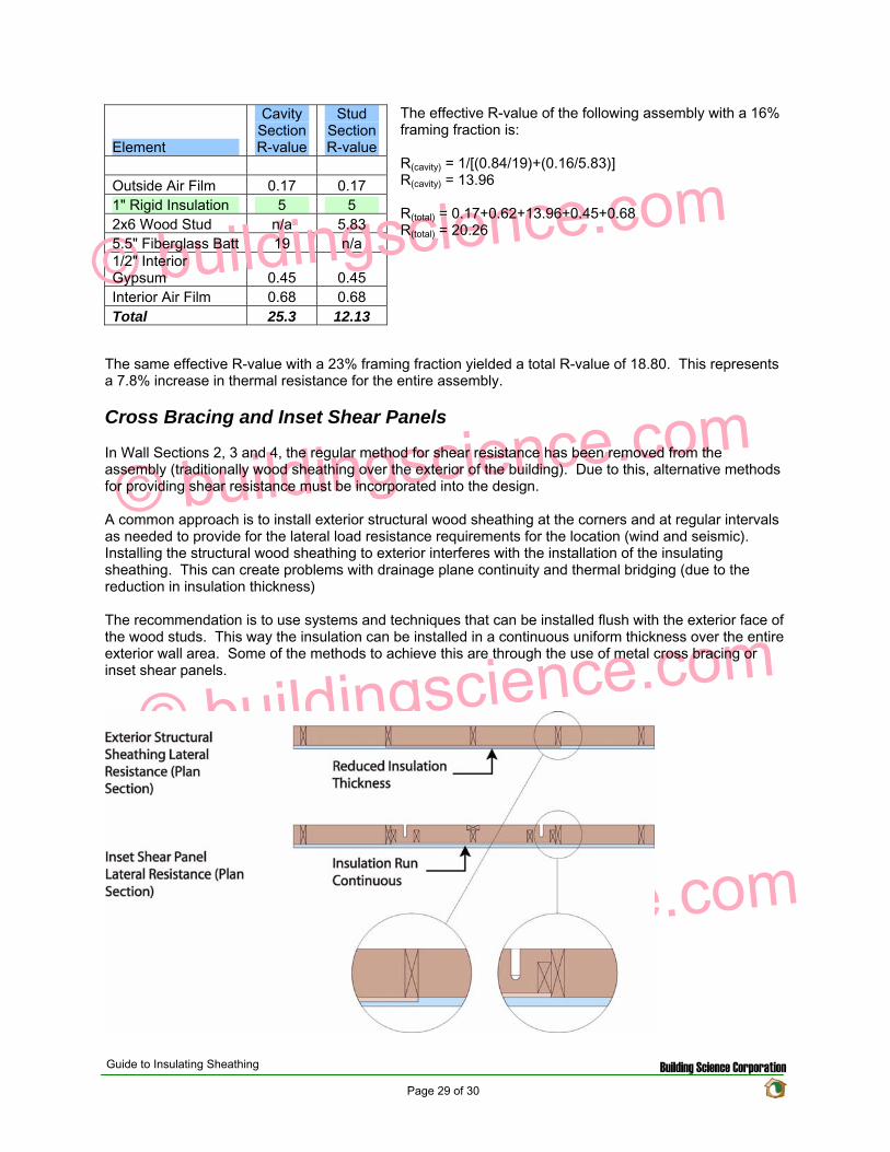
copy buildingsciencecom
copy buildingsciencecom
copy buildingsciencecom
copy buildingsciencecom
Element
Cavity Section R-value
Stud Section R-value
Outside Air Film 017 017 1 Rigid Insulation 5 5 2x6 Wood Stud na 583 55 Fiberglass Batt 19 na 12 Interior Gypsum 045 045 Interior Air Film 068 068 Total 253 1213
The effective R-value of the following assembly with a 16 framing fraction is
R(cavity) = 1[(08419)+(016583)] R(cavity) = 1396
R(total) = 017+062+1396+045+068 R(total) = 2026
The same effective R-value with a 23 framing fraction yielded a total R-value of 1880 This represents a 78 increase in thermal resistance for the entire assembly
Cross Bracing and Inset Shear Panels
In Wall Sections 2 3 and 4 the regular method for shear resistance has been removed from the assembly (traditionally wood sheathing over the exterior of the building) Due to this alternative methods for providing shear resistance must be incorporated into the design
A common approach is to install exterior structural wood sheathing at the corners and at regular intervals as needed to provide for the lateral load resistance requirements for the location (wind and seismic) Installing the structural wood sheathing to exterior interferes with the installation of the insulating sheathing This can create problems with drainage plane continuity and thermal bridging (due to the reduction in insulation thickness)
The recommendation is to use systems and techniques that can be installed flush with the exterior face of the wood studs This way the insulation can be installed in a continuous uniform thickness over the entire exterior wall area Some of the methods to achieve this are through the use of metal cross bracing or inset shear panels
Guide to Insulating Sheathing Building Science Corporation Page 29 of 30
With metal cross bracing the thickness of the metal braces are insignificant and do not interfere with the installation of the insulating sheathing The capacity of the metal cross bracing however may not be adequate for areas with high wind loads andor seismic activity In these locations a more robust form of lateral load resistance may be needed
copy buildingsciencecom
copy buildingsciencecom
copy buildingsciencecom
copy buildingsciencecom
Inset shear panels can provide for high levels of lateral load resistance and can be used in all wind and seismic zones Inset shear panels are wood framed panels that fit within the stud spacing of the wall assembly In this way the exterior face of the panel is flush with the exterior face of the wood studs
Depending on the area of the country different requirements for wind and seismic resistance are required The method chosen will depend on the individual code requirements for the area
Guide to Insulating Sheathing Building Science Corporation Page 30 of 30
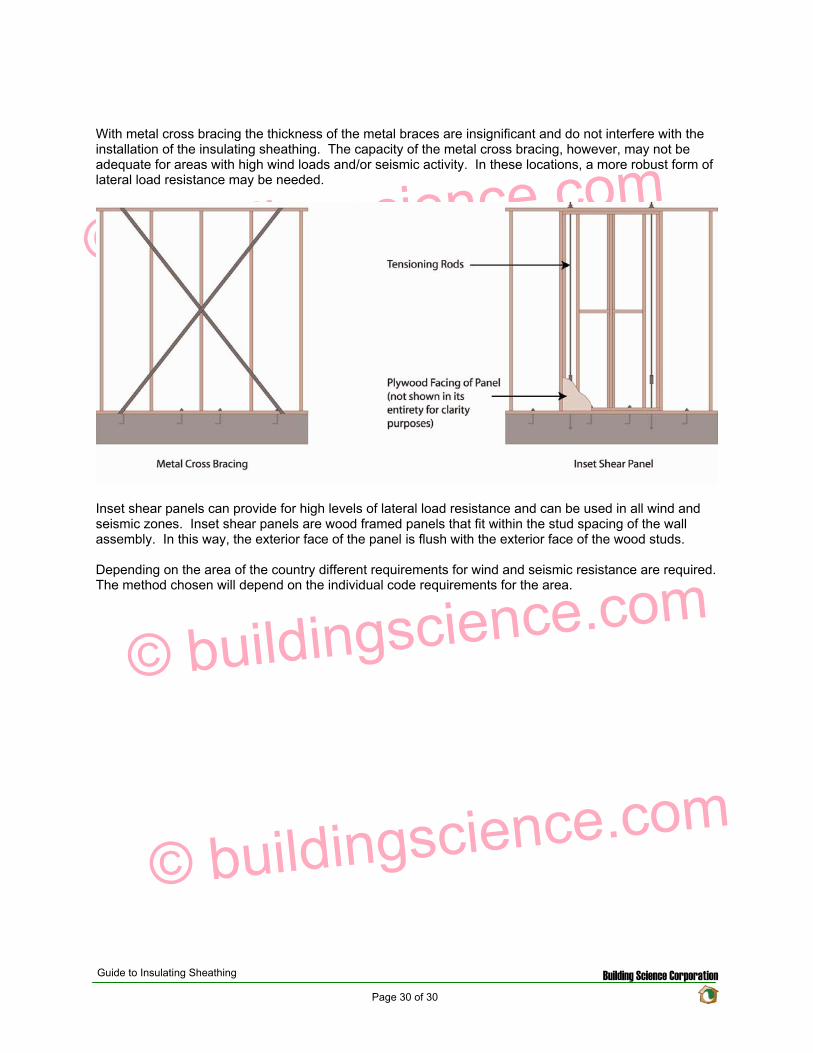


![Installing Exterior Insulation in Cold Climates · by Thorsten Chlupp. 32 l JLC l MAY 2009 Installing Exterior Insulation in Cold Climates ... Ab`cQbc`OZ aVSObVW\U 1]\bW\c]ca PSOR](https://img.pdfslide.net/doc/110x75/5adbc3d97f8b9a9d4d8b7ae1/installing-exterior-insulation-in-cold-thorsten-chlupp-32-l-jlc-l-may-2009-installing.jpg)


![Innovative materials for road insulation in cold climates ... · PDF filethickness to ensure adequate ... material [Bilodeau et al., 2016]. Insulation also enhances the critical](https://img.pdfslide.net/doc/110x75/5aa45e1f7f8b9ae7438bf98a/innovative-materials-for-road-insulation-in-cold-climates-to-ensure-adequate.jpg)