Embed Size (px)
Citation preview
Guide toProducts and Technol-
ogy
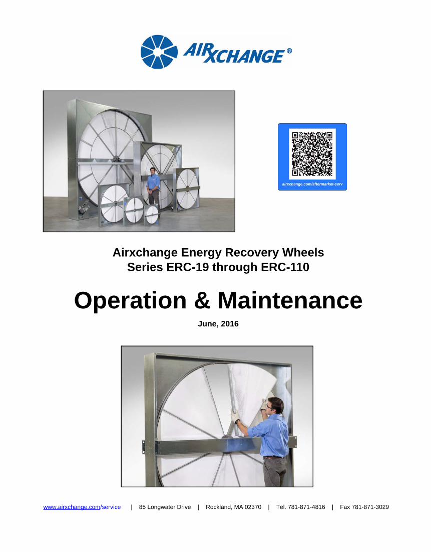
Airxchange Energy Recovery WheelsSeries ERC-19 through ERC-110
Operation & Maintenance June, 2016
www.airxchange.com/service | 85 Longwater Drive | Rockland, MA 02370 | Tel. 781-871-4816 | Fax 781-871-3029
2
Table of Contents
Safety ........................................................................................................................ 2
Product Overview ..................................................................................................... 3About Airxchange Energy Recovery Wheels .............................................................................3Service Tools .............................................................................................................................5
Operating Instructions ............................................................................................. 6Pre-Startup.................................................................................................................................6Post-Startup ...............................................................................................................................8
Routine and Preventative Maintenance ................................................................. 9Inspection Checklist ...................................................................................................................9Cleaning Airxchange Segments...............................................................................................10
Segment Removal/Installation .............................................................................. 1219 to 25-inch Monolithic Wheel ................................................................................................1325 to 30 Inch Segmented Wheel ..............................................................................................1436 to 86-inch Segmented Wheel ..............................................................................................1692 to 110-inch Segmented Wheel ............................................................................................18
Record Product Information for Reference ......................................................... 20
Safety
Electrical Safety
Safety around Metal and Moving Parts
WARNING
Before servicing entire HVAC system, turn off the main disconnect to the unit. Use the site-specific Lockout-Tagout procedure.
WARNING
Do not touch moving parts.
Use site specific Lockout-tagout procedure to turn off all moving parts in the HVAC system before servicing.
Tuck in all loose clothing when near moving parts.
Wear gloves when handling HVAC components.
Safety:
3
Product Overview
About Airxchange Energy Recovery Wheels
Unless noted, the information in this manual applies to allavailable models of Airxchange energy recovery wheels.
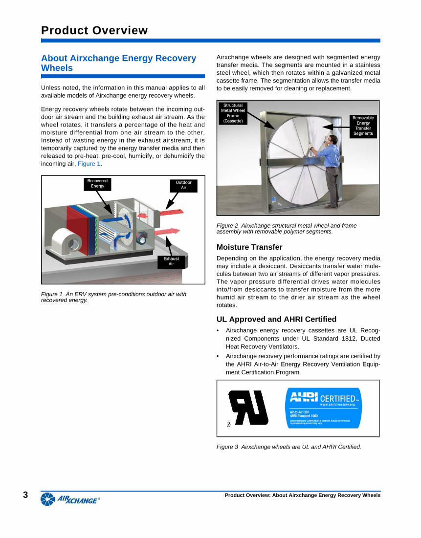
Energy recovery wheels rotate between the incoming out-door air stream and the building exhaust air stream. As thewheel rotates, it transfers a percentage of the heat andmoisture differential from one air stream to the other.Instead of wasting energy in the exhaust airstream, it istemporarily captured by the energy transfer media and thenreleased to pre-heat, pre-cool, humidify, or dehumidify theincoming air, Figure 1.
Figure 1 An ERV system pre-conditions outdoor air with recovered energy.
Airxchange wheels are designed with segmented energytransfer media. The segments are mounted in a stainlesssteel wheel, which then rotates within a galvanized metalcassette frame. The segmentation allows the transfer mediato be easily removed for cleaning or replacement.
Figure 2 Airxchange structural metal wheel and frame assembly with removable polymer segments.
Moisture TransferDepending on the application, the energy recovery mediamay include a desiccant. Desiccants transfer water mole-cules between two air streams of different vapor pressures.The vapor pressure differential drives water moleculesinto/from desiccants to transfer moisture from the morehumid air stream to the drier air stream as the wheelrotates.
UL Approved and AHRI Certified• Airxchange energy recovery cassettes are UL Recog-
nized Components under UL Standard 1812, DuctedHeat Recovery Ventilators.
• Airxchange recovery performance ratings are certified bythe AHRI Air-to-Air Energy Recovery Ventilation Equip-ment Certification Program.
Figure 3 Airxchange wheels are UL and AHRI Certified.
B
A
A
Polymer Media
Surface
Metal Wheel and Frame Assembly
Outdoor Air
Exhaust Air
Recovered Energy
B
A
A
Structural Metal Wheel
Frame (Cassette)
RemovableEnergy
Transfer Segments
Product Overview: About Airxchange Energy Recovery Wheels
4
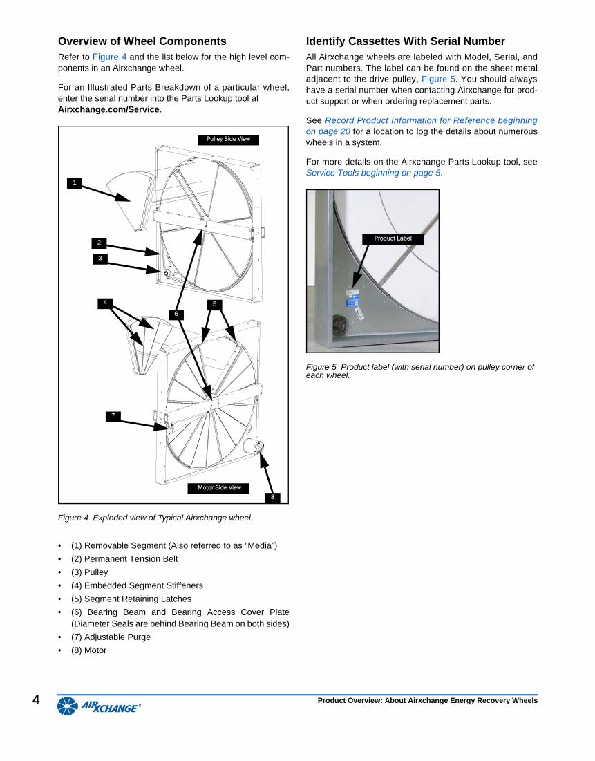
Overview of Wheel ComponentsRefer to Figure 4 and the list below for the high level com-ponents in an Airxchange wheel.
For an Illustrated Parts Breakdown of a particular wheel,enter the serial number into the Parts Lookup tool at Airxchange.com/Service.
Figure 4 Exploded view of Typical Airxchange wheel.
• (1) Removable Segment (Also referred to as “Media”)
• (2) Permanent Tension Belt
• (3) Pulley
• (4) Embedded Segment Stiffeners
• (5) Segment Retaining Latches
• (6) Bearing Beam and Bearing Access Cover Plate(Diameter Seals are behind Bearing Beam on both sides)
• (7) Adjustable Purge
• (8) Motor
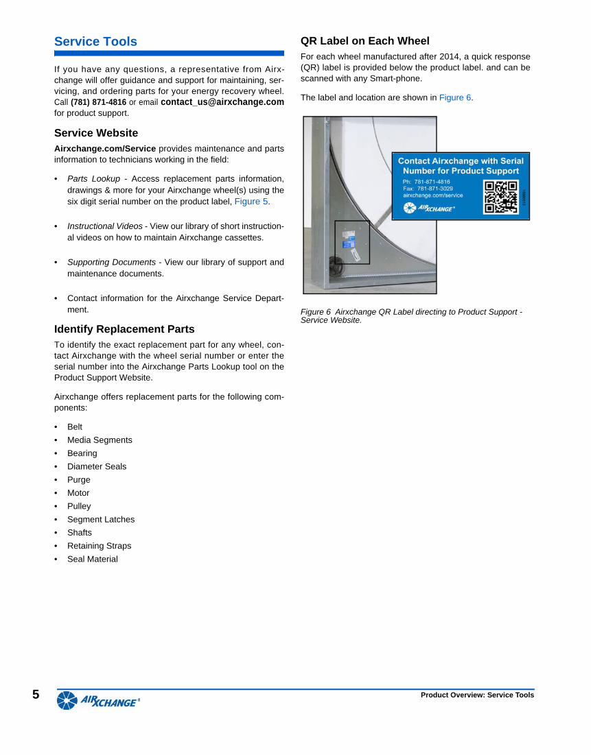
Identify Cassettes With Serial NumberAll Airxchange wheels are labeled with Model, Serial, andPart numbers. The label can be found on the sheet metaladjacent to the drive pulley, Figure 5. You should alwayshave a serial number when contacting Airxchange for prod-uct support or when ordering replacement parts.
See Record Product Information for Reference beginningon page 20 for a location to log the details about numerouswheels in a system.
For more details on the Airxchange Parts Lookup tool, seeService Tools beginning on page 5.
Figure 5 Product label (with serial number) on pulley corner of each wheel.
3
1
2
8
5
7
4
6
Pulley Side ViewPulley Side View
Motor Side View
Product Label
Product Overview: About Airxchange Energy Recovery Wheels
5
Service Tools
If you have any questions, a representative from Airx-change will offer guidance and support for maintaining, ser-vicing, and ordering parts for your energy recovery wheel.Call (781) 871-4816 or email [email protected] product support.
Service WebsiteAirxchange.com/Service provides maintenance and partsinformation to technicians working in the field:
• Parts Lookup - Access replacement parts information,drawings & more for your Airxchange wheel(s) using thesix digit serial number on the product label, Figure 5.
• Instructional Videos - View our library of short instruction-al videos on how to maintain Airxchange cassettes.
• Supporting Documents - View our library of support andmaintenance documents.
• Contact information for the Airxchange Service Depart-ment.
Identify Replacement Parts To identify the exact replacement part for any wheel, con-tact Airxchange with the wheel serial number or enter theserial number into the Airxchange Parts Lookup tool on theProduct Support Website.
Airxchange offers replacement parts for the following com-ponents:
• Belt
• Media Segments
• Bearing
• Diameter Seals
• Purge
• Motor
• Pulley
• Segment Latches
• Shafts
• Retaining Straps
• Seal Material
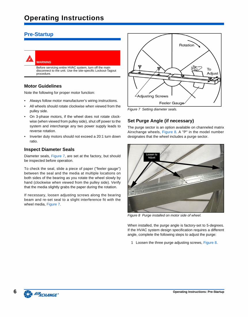
QR Label on Each WheelFor each wheel manufactured after 2014, a quick response(QR) label is provided below the product label. and can bescanned with any Smart-phone.
The label and location are shown in Figure 6.
Figure 6 Airxchange QR Label directing to Product Support - Service Website.
B
Product Overview: Service Tools
6
Operating Instructions
Pre-Startup
Motor GuidelinesNote the following for proper motor function:
• Always follow motor manufacturer’s wiring instructions.
• All wheels should rotate clockwise when viewed from thepulley side.
• On 3-phase motors, if the wheel does not rotate clock-wise (when viewed from pulley side), shut off power to thesystem and interchange any two power supply leads toreverse rotation.
• Inverter duty motors should not exceed a 20:1 turn downratio.
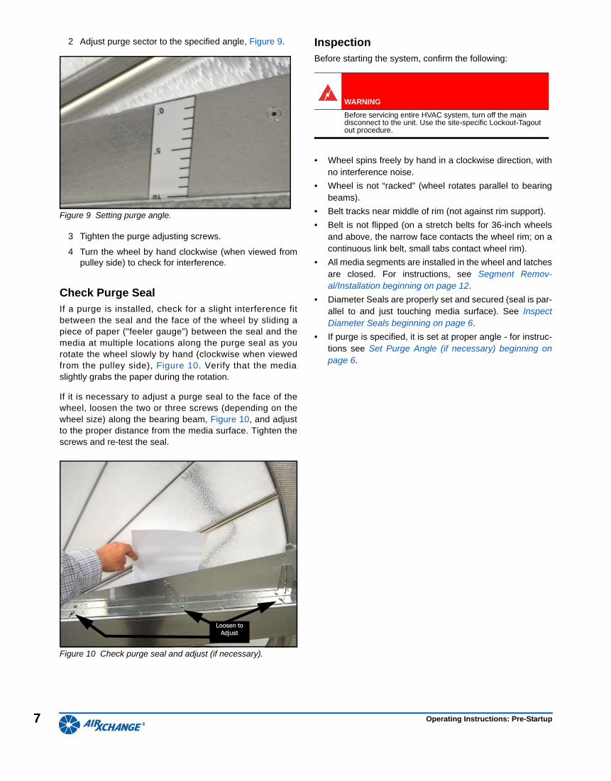
Inspect Diameter SealsDiameter seals, Figure 7, are set at the factory, but shouldbe inspected before operation.
To check the seal, slide a piece of paper ("feeler gauge”)between the seal and the media at multiple locations onboth sides of the bearing as you rotate the wheel slowly byhand (clockwise when viewed from the pulley side). Verifythat the media slightly grabs the paper during the rotation.
If necessary, loosen adjusting screws along the bearingbeam and re-set seal to a slight interference fit with thewheel media, Figure 7.
Figure 7 Setting diameter seals.
Set Purge Angle (if necessary)The purge sector is an option available on channeled matrixAirxchange wheels, Figure 8. A "P" in the model numberdesignates that the wheel includes a purge sector.
Figure 8 Purge installed on motor side of wheel.
When installed, the purge angle is factory-set to 5-degrees.If the HVAC system design specification requires a differentangle, complete the following steps to adjust the purge:
1 Loosen the three purge adjusting screws, Figure 8.
WARNING
Before servicing entire HVAC system, turn off the main disconnect to the unit. Use the site-specific Lockout-Tagout procedure.
Loosen to Adjust
Operating Instructions: Pre-Startup
7
2 Adjust purge sector to the specified angle, Figure 9.
Figure 9 Setting purge angle.
3 Tighten the purge adjusting screws.
4 Turn the wheel by hand clockwise (when viewed frompulley side) to check for interference.
Check Purge SealIf a purge is installed, check for a slight interference fitbetween the seal and the face of the wheel by sliding apiece of paper ("feeler gauge”) between the seal and themedia at multiple locations along the purge seal as yourotate the wheel slowly by hand (clockwise when viewedfrom the pulley side), Figure 10. Verify that the mediaslightly grabs the paper during the rotation.
If it is necessary to adjust a purge seal to the face of thewheel, loosen the two or three screws (depending on thewheel size) along the bearing beam, Figure 10, and adjustto the proper distance from the media surface. Tighten thescrews and re-test the seal.
Figure 10 Check purge seal and adjust (if necessary).
InspectionBefore starting the system, confirm the following:
• Wheel spins freely by hand in a clockwise direction, withno interference noise.
• Wheel is not “racked" (wheel rotates parallel to bearingbeams).
• Belt tracks near middle of rim (not against rim support).
• Belt is not flipped (on a stretch belts for 36-inch wheelsand above, the narrow face contacts the wheel rim; on acontinuous link belt, small tabs contact wheel rim).
• All media segments are installed in the wheel and latchesare closed. For instructions, see Segment Remov-al/Installation beginning on page 12.
• Diameter Seals are properly set and secured (seal is par-allel to and just touching media surface). See InspectDiameter Seals beginning on page 6.
• If purge is specified, it is set at proper angle - for instruc-tions see Set Purge Angle (if necessary) beginning onpage 6.
Loosen to Adjust
WARNING
Before servicing entire HVAC system, turn off the main disconnect to the unit. Use the site-specific Lockout-Tagout out procedure.
Operating Instructions: Pre-Startup
8
Post-Startup
Inspection After applying power to system, confirm the following:
• Verify that the wheel is rotating clockwise (when viewedfrom the pulley side).
• On 3-phase motors, if the wheel does not rotate clock-wise (when viewed from pulley side), shut off the powerto the system and interchange any two power supplyleads to reverse rotation.
• Visually inspect belt; ensure belt is tracking near the cen-ter of the rim.
• Verify that wheel speed is approximately 45-50 RPMs(rotating clockwise when viewed from pulley side).
• No excessive noise (scraping, brushing, banging etc.).
• Running amps do not exceed nameplate Full LoadAmperes (FLA).
Configuring Wheel ControlsAirxchange does not offer any direct speed controls for thewheel.
To confirm that wheel speed is responding to the field sup-plied speed control, consult the energy recovery wheel por-t ion of the original equipment manufacturer (OEM)operating manual.
Items to Check Before Beginning Normal OperationVerify the following:
• The area around the energy recovery wheel is free ofdebris.
• Cabinet doors are closed and secure.
• Power is restored to unit.
Operating Instructions: Post-Startup
9
Routine and Preventative Maintenance
Inspection Checklist
Airxchange recommends inspecting the wheel once peryear to verify that the wheel, motor, belt, energy transfersegments, and seals are all in good working order. Routinemaintenance is not required other than to clean the energytransfer media periodically on a schedule that is determinedby the application (see next page for details).
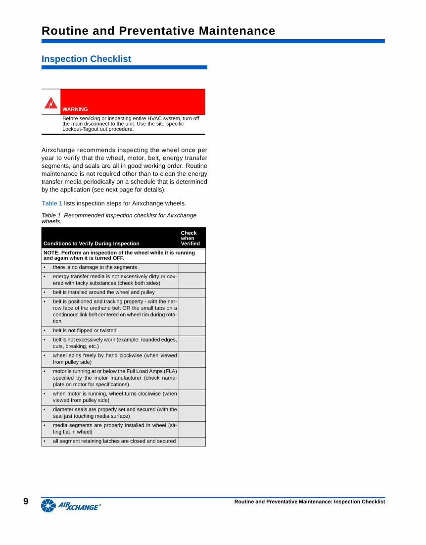
Table 1 lists inspection steps for Airxchange wheels.
WARNING
Before servicing or inspecting entire HVAC system, turn off the main disconnect to the unit. Use the site-specific Lockout-Tagout out procedure.
Table 1 Recommended inspection checklist for Airxchange wheels.
Conditions to Verify During Inspection
Check when Verified
NOTE: Perform an inspection of the wheel while it is running and again when it is turned OFF.
• there is no damage to the segments
• energy transfer media is not excessively dirty or cov-ered with tacky substances (check both sides)
• belt is installed around the wheel and pulley
• belt is positioned and tracking property - with the nar-row face of the urethane belt OR the small tabs on acontinuous link belt centered on wheel rim during rota-tion
• belt is not flipped or twisted
• belt is not excessively worn (example: rounded edges,cuts, breaking, etc.)
• wheel spins freely by hand clockwise (when viewedfrom pulley side)
• motor is running at or below the Full Load Amps (FLA)specified by the motor manufacturer (check name-plate on motor for specifications)
• when motor is running, wheel turns clockwise (whenviewed from pulley side)
• diameter seals are properly set and secured (with theseal just touching media surface)
• media segments are properly installed in wheel (sit-ting flat in wheel)
• all segment retaining latches are closed and secured
Routine and Preventative Maintenance: Inspection Checklist
10
Cleaning Airxchange Segments
All Airxchange wheels 25-inches in diameter and larger fea-ture segmented energy transfer segments for easy removaland cleanings - per the application requirements. The poly-mer media segments are lightweight and can be lifted by asingle person. This section briefly describes how to deter-mine the need for cleaning and, if necessary, clean theAirxchange segments.
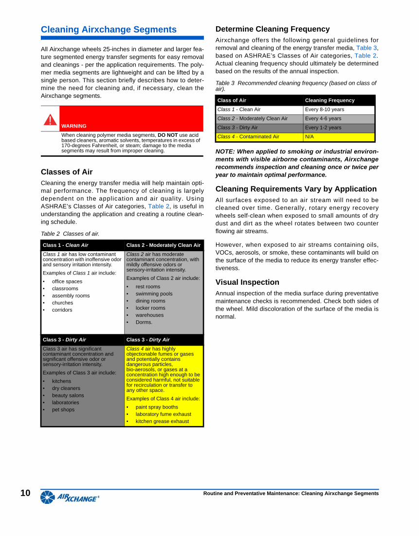
Classes of AirCleaning the energy transfer media will help maintain opti-mal performance. The frequency of cleaning is largelydependent on the application and air quality. UsingASHRAE’s Classes of Air categories, Table 2, is useful inunderstanding the application and creating a routine clean-ing schedule.
Determine Cleaning FrequencyAirxchange offers the following general guidelines forremoval and cleaning of the energy transfer media, Table 3,based on ASHRAE’s Classes of Air categories, Table 2.Actual cleaning frequency should ultimately be determinedbased on the results of the annual inspection.
NOTE: When applied to smoking or industrial environ-ments with visible airborne contaminants, Airxchangerecommends inspection and cleaning once or twice peryear to maintain optimal performance.
Cleaning Requirements Vary by ApplicationAll surfaces exposed to an air stream will need to becleaned over time. Generally, rotary energy recoverywheels self-clean when exposed to small amounts of drydust and dirt as the wheel rotates between two counterflowing air streams.
However, when exposed to air streams containing oils,VOCs, aerosols, or smoke, these contaminants will build onthe surface of the media to reduce its energy transfer effec-tiveness.
Visual InspectionAnnual inspection of the media surface during preventativemaintenance checks is recommended. Check both sides ofthe wheel. Mild discoloration of the surface of the media isnormal.
WARNING
When cleaning polymer media segments, DO NOT use acid based cleaners, aromatic solvents, temperatures in excess of 170-degrees Fahrenheit, or steam; damage to the media segments may result from improper cleaning.
Table 2 Classes of air.
Class 1 - Clean Air Class 2 - Moderately Clean Air
Class 1 air has low contaminant concentration with inoffensive odor and sensory irritation intensity.
Examples of Class 1 air include:
• office spaces• classrooms• assembly rooms• churches• corridors
Class 2 air has moderate contaminant concentration, with mildly offensive odors or sensory-irritation intensity.
Examples of Class 2 air include:
• rest rooms• swimming pools• dining rooms• locker rooms• warehouses• Dorms.
Class 3 - Dirty Air Class 3 - Dirty Air
Class 3 air has significant contaminant concentration and significant offensive odor or sensory-irritation intensity.
Examples of Class 3 air include:
• kitchens• dry cleaners• beauty salons• laboratories• pet shops
Class 4 air has highly objectionable fumes or gases and potentially contains dangerous particles, bio-aerosols, or gases at a concentration high enough to be considered harmful, not suitable for recirculation or transfer to any other space.
Examples of Class 4 air include:
• paint spray booths• laboratory fume exhaust• kitchen grease exhaust
Table 3 Recommended cleaning frequency (based on class of air).
Class of Air Cleaning Frequency
Class 1 - Clean Air Every 8-10 years
Class 2 - Moderately Clean Air Every 4-6 years
Class 3 - Dirty Air Every 1-2 years
Class 4 - Contaminated Air N/A
Routine and Preventative Maintenance: Cleaning Airxchange Segments
11
Cleaning MethodsTo clean a buildup of dry contaminants on the media sur-face, brush or vacuum the surface on both sides to removeall debris, including between the layers of polymer. Clean,unobstructed passageways provide the maximum energysavings for the lowest operating cost.
To clean media surfaces that have a buildup of contain-ments, Airxchange recommends soaking the segment over-night to effectively remove all contaminants and restore theheat/moisture transfer performance.
There are several methods to remove contaminant buildup:
• The best method of removing buildup is to soak the seg-ment overnight in a five-percent solution of a non-acidbased coil cleaner. WARNING: Monolithic wheels withinternal bearings should not be soaked to avoid cor-roding bearing.
After soaking, rinse the segments until the water runsclear and then allow excess water to drain prior to rein-stalling the segments. A small amount of moisture on themedia will be dried out by the airflow.
• Another option is to run water from a hose through theremoved media while brushing, though this method is notas effective as the overnight soak.
About Discoloration of Media SurfaceOnce clean, media segments may remain slightly discol-ored. Surface discoloration does not affect the perfor-mance of the wheel.
Optional Cleaning Methods• If a tub is not available for soaking, a makeshift tub can
be easily constructed out of wood boards and any water-proof material, such as a polyethylene sheet. Thenon-acid based coil cleaner is not corrosive to the poly-mer media or polyethylene sheet.
• For applications with multiple identical wheels, keeping aspare set of segments available can eliminate system dis-ruptions during cleaning. Contact Airxchange for moreinformation.
Routine and Preventative Maintenance: Cleaning Airxchange Segments
12
Segment Removal/Installation
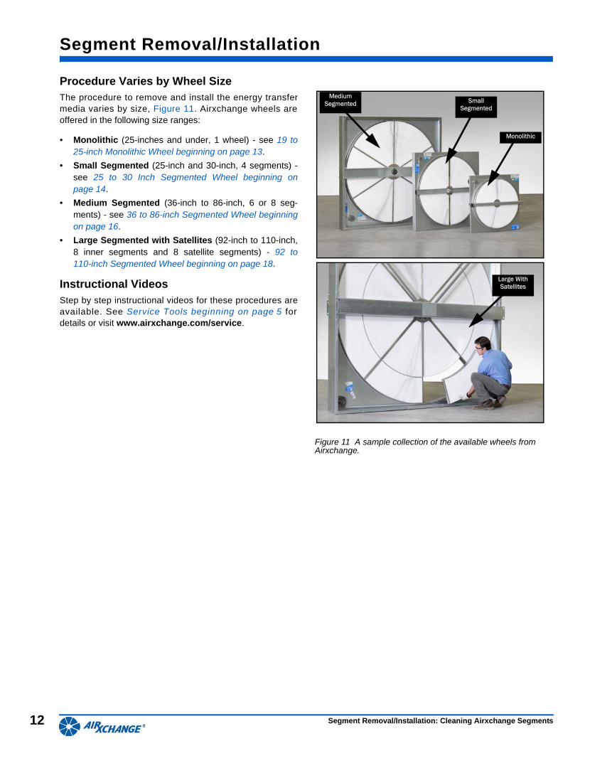
Procedure Varies by Wheel Size The procedure to remove and install the energy transfermedia varies by size, Figure 11. Airxchange wheels areoffered in the following size ranges:
• Monolithic (25-inches and under, 1 wheel) - see 19 to25-inch Monolithic Wheel beginning on page 13.
• Small Segmented (25-inch and 30-inch, 4 segments) -see 25 to 30 Inch Segmented Wheel beginning onpage 14.
• Medium Segmented (36-inch to 86-inch, 6 or 8 seg-ments) - see 36 to 86-inch Segmented Wheel beginningon page 16.
• Large Segmented with Satellites (92-inch to 110-inch,8 inner segments and 8 satellite segments) - 92 to110-inch Segmented Wheel beginning on page 18.
Instructional VideosStep by step instructional videos for these procedures areavailable. See Service Tools beginning on page 5 fordetails or visit www.airxchange.com/service.
Figure 11 A sample collection of the available wheels from Airxchange.
Monolithic
Medium Segmented Small
Segmented
Large With Satellites
Segment Removal/Installation: Cleaning Airxchange Segments
13
19 to 25-inch Monolithic Wheel
Complete the following procedures to remove and install a19 to 25-inch monolithic segment.
Tools• Phillips screwdriver
• nut driver or socket set
• gloves
Series 19 to 21 Wheel Removal and Installation
1 Disconnect power to the wheel.
2 If possible, remove wheel frame from cabinet.
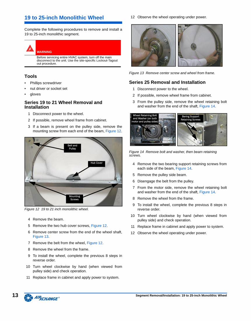
3 If a beam is present on the pulley side, remove themounting screw from each end of the beam, Figure 12.
Figure 12 19 to 21 inch monolithic wheel.
4 Remove the beam.
5 Remove the two hub cover screws, Figure 12.
6 Remove center screw from the end of the wheel shaft,Figure 13.
7 Remove the belt from the wheel, Figure 12.
8 Remove the wheel from the frame.
9 To install the wheel, complete the previous 8 steps inreverse order.
10 Turn wheel clockwise by hand (when viewed frompulley side) and check operation.
11 Replace frame in cabinet and apply power to system.
12 Observe the wheel operating under power.
Figure 13 Remove center screw and wheel from frame.
Series 25 Removal and Installation1 Disconnect power to the wheel.
2 If possible, remove wheel frame from cabinet.
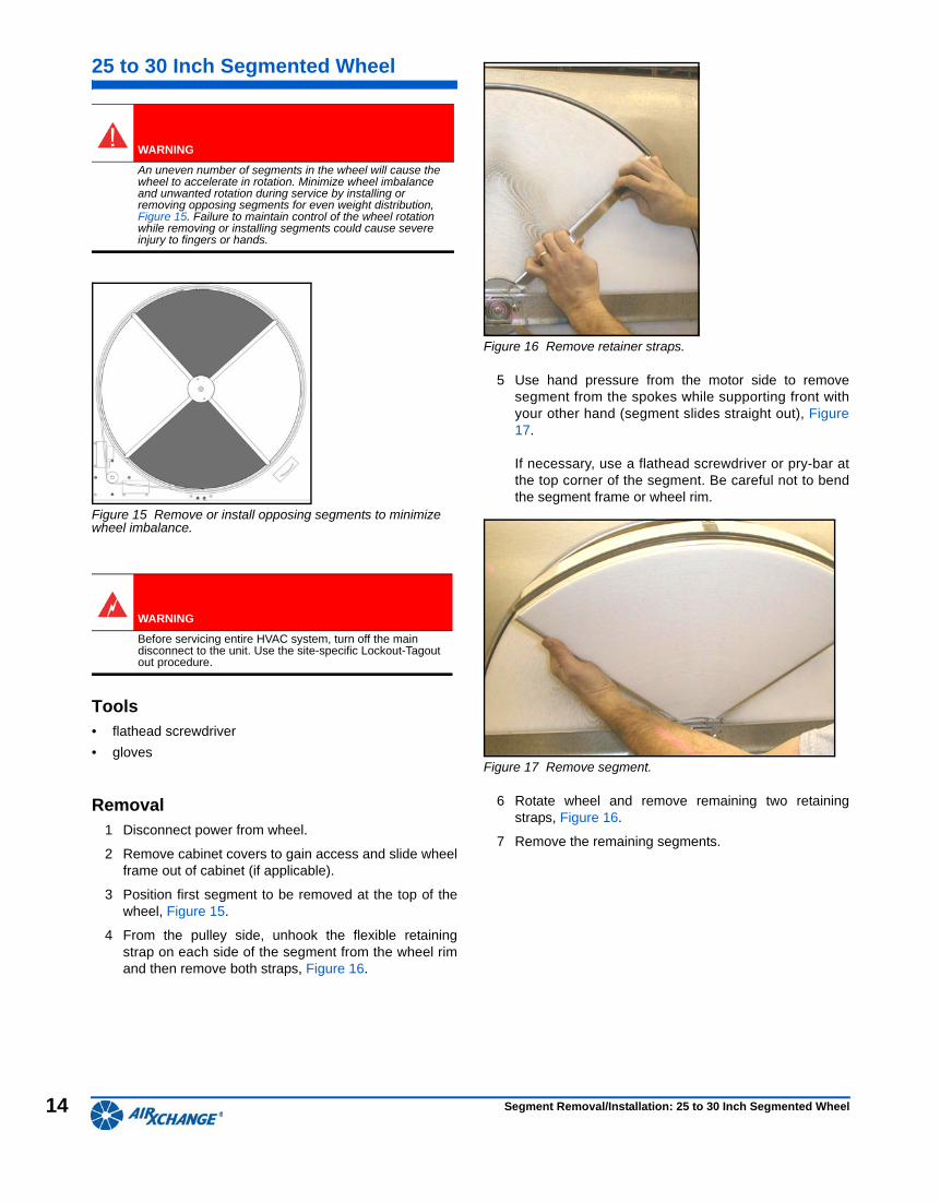
3 From the pulley side, remove the wheel retaining boltand washer from the end of the shaft, Figure 14.
Figure 14 Remove bolt and washer, then beam retaining screws.
4 Remove the two bearing support retaining screws fromeach side of the beam, Figure 14.
5 Remove the pulley side beam.
6 Disengage the belt from the pulley.
7 From the motor side, remove the wheel retaining boltand washer from the end of the shaft, Figure 14.
8 Remove the wheel from the frame.
9 To install the wheel, complete the previous 8 steps inreverse order.
10 Turn wheel clockwise by hand (when viewed frompulley side) and check operation.
11 Replace frame in cabinet and apply power to system.
12 Observe the wheel operating under power.
WARNING
Before servicing entire HVAC system, turn off the main disconnect to the unit. Use the site-specific Lockout-Tagout out procedure.
Belt and Pulley
Hub Cover
Mounting Screws
Wheel Retaining Bolt and Washer (on both
motor and pulley sides)
Bering Support Retaining Screws
Segment Removal/Installation: 19 to 25-inch Monolithic Wheel
14
25 to 30 Inch Segmented Wheel
Figure 15 Remove or install opposing segments to minimize wheel imbalance.
Tools• flathead screwdriver
• gloves
Removal1 Disconnect power from wheel.
2 Remove cabinet covers to gain access and slide wheelframe out of cabinet (if applicable).
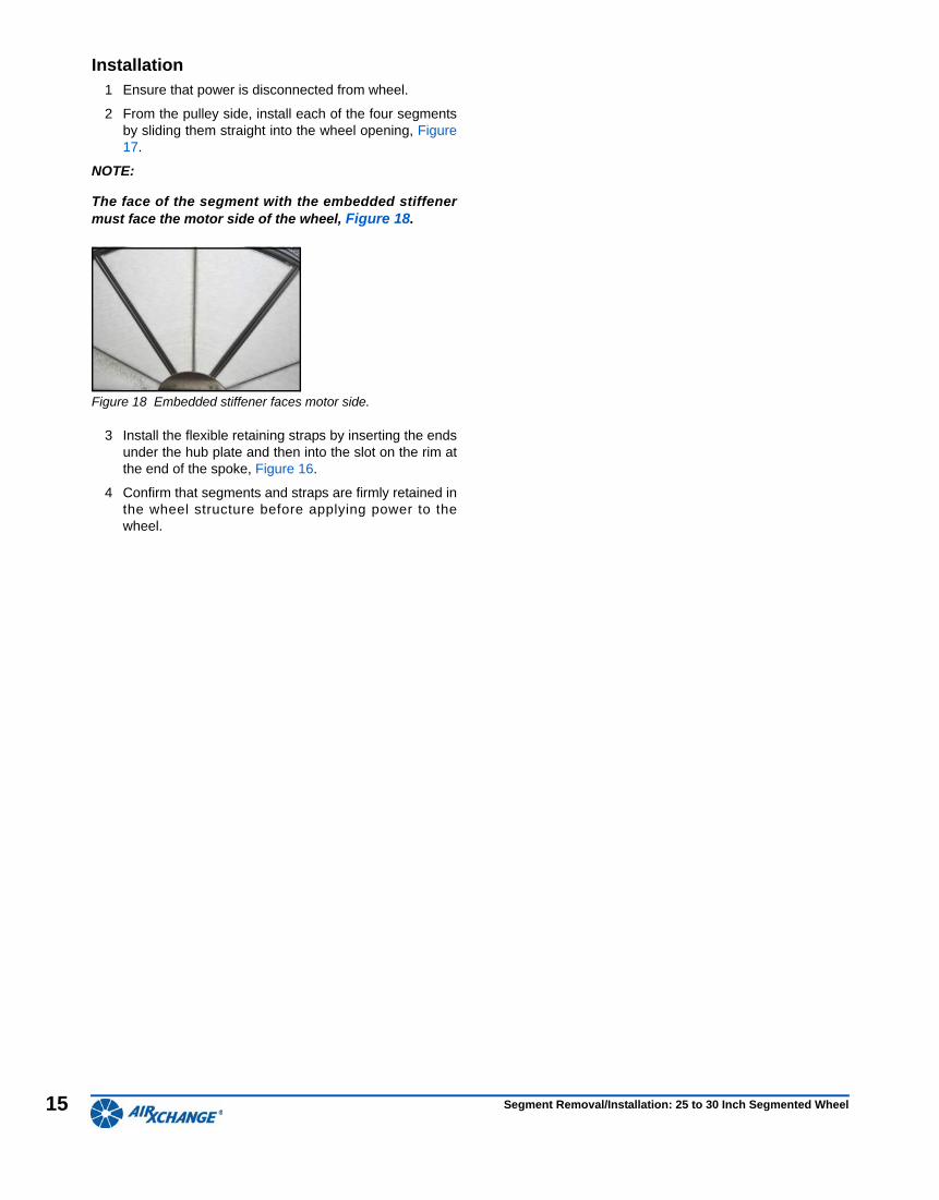
3 Position first segment to be removed at the top of thewheel, Figure 15.
4 From the pulley side, unhook the flexible retainingstrap on each side of the segment from the wheel rimand then remove both straps, Figure 16.
Figure 16 Remove retainer straps.
5 Use hand pressure from the motor side to removesegment from the spokes while supporting front withyour other hand (segment slides straight out), Figure17.
If necessary, use a flathead screwdriver or pry-bar atthe top corner of the segment. Be careful not to bendthe segment frame or wheel rim.
Figure 17 Remove segment.
6 Rotate wheel and remove remaining two retainingstraps, Figure 16.
7 Remove the remaining segments.
WARNING
An uneven number of segments in the wheel will cause the wheel to accelerate in rotation. Minimize wheel imbalance and unwanted rotation during service by installing or removing opposing segments for even weight distribution, Figure 15. Failure to maintain control of the wheel rotation while removing or installing segments could cause severe injury to fingers or hands.
WARNING
Before servicing entire HVAC system, turn off the main disconnect to the unit. Use the site-specific Lockout-Tagout out procedure.
Segment Removal/Installation: 25 to 30 Inch Segmented Wheel
15
Installation1 Ensure that power is disconnected from wheel.
2 From the pulley side, install each of the four segmentsby sliding them straight into the wheel opening, Figure17.
NOTE:
The face of the segment with the embedded stiffenermust face the motor side of the wheel, Figure 18.
Figure 18 Embedded stiffener faces motor side.
3 Install the flexible retaining straps by inserting the endsunder the hub plate and then into the slot on the rim atthe end of the spoke, Figure 16.
4 Confirm that segments and straps are firmly retained inthe wheel structure before applying power to thewheel.
Segment Removal/Installation: 25 to 30 Inch Segmented Wheel
16
36 to 86-inch Segmented Wheel
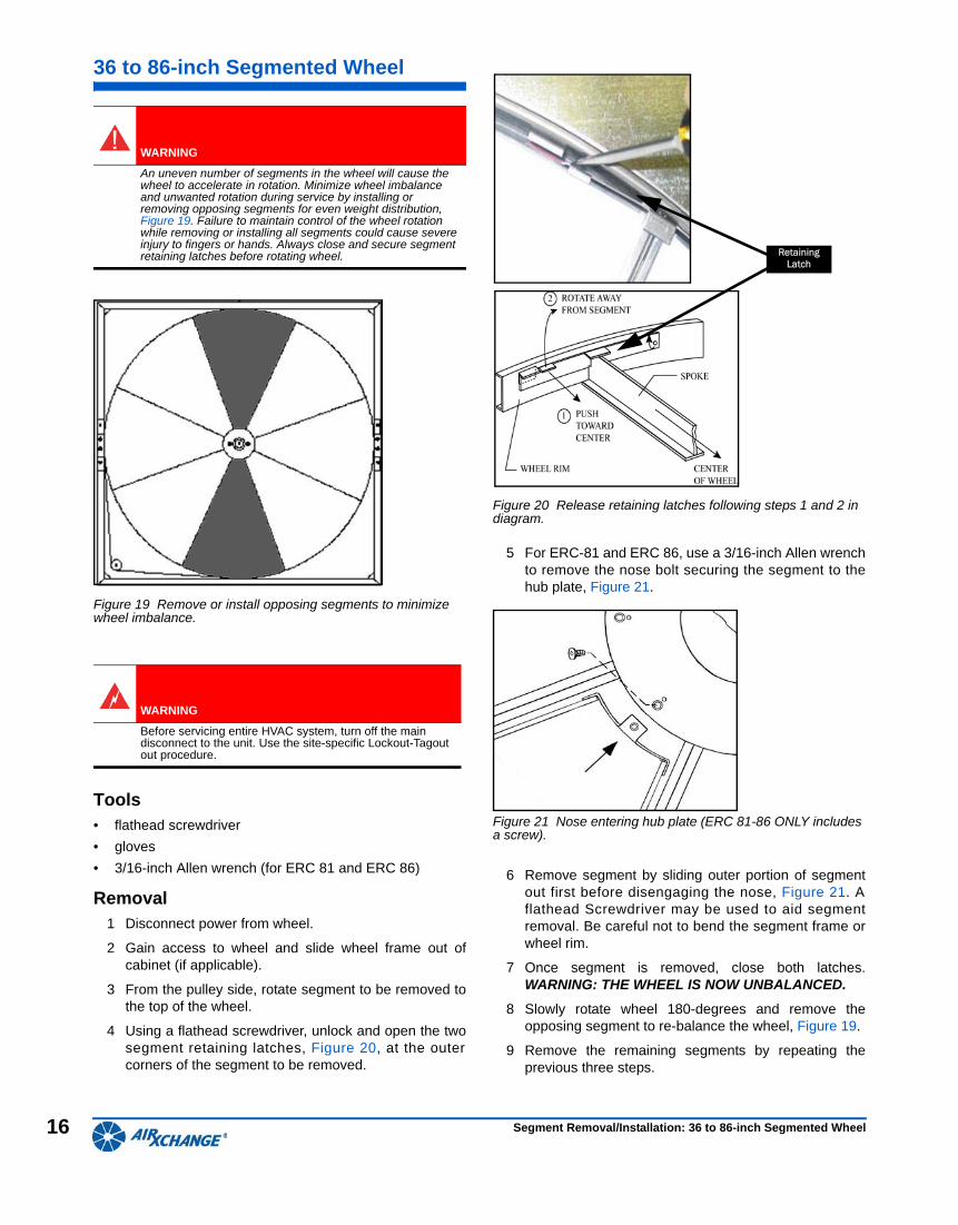
Figure 19 Remove or install opposing segments to minimize wheel imbalance.
Tools• flathead screwdriver
• gloves
• 3/16-inch Allen wrench (for ERC 81 and ERC 86)
Removal1 Disconnect power from wheel.
2 Gain access to wheel and slide wheel frame out ofcabinet (if applicable).
3 From the pulley side, rotate segment to be removed tothe top of the wheel.
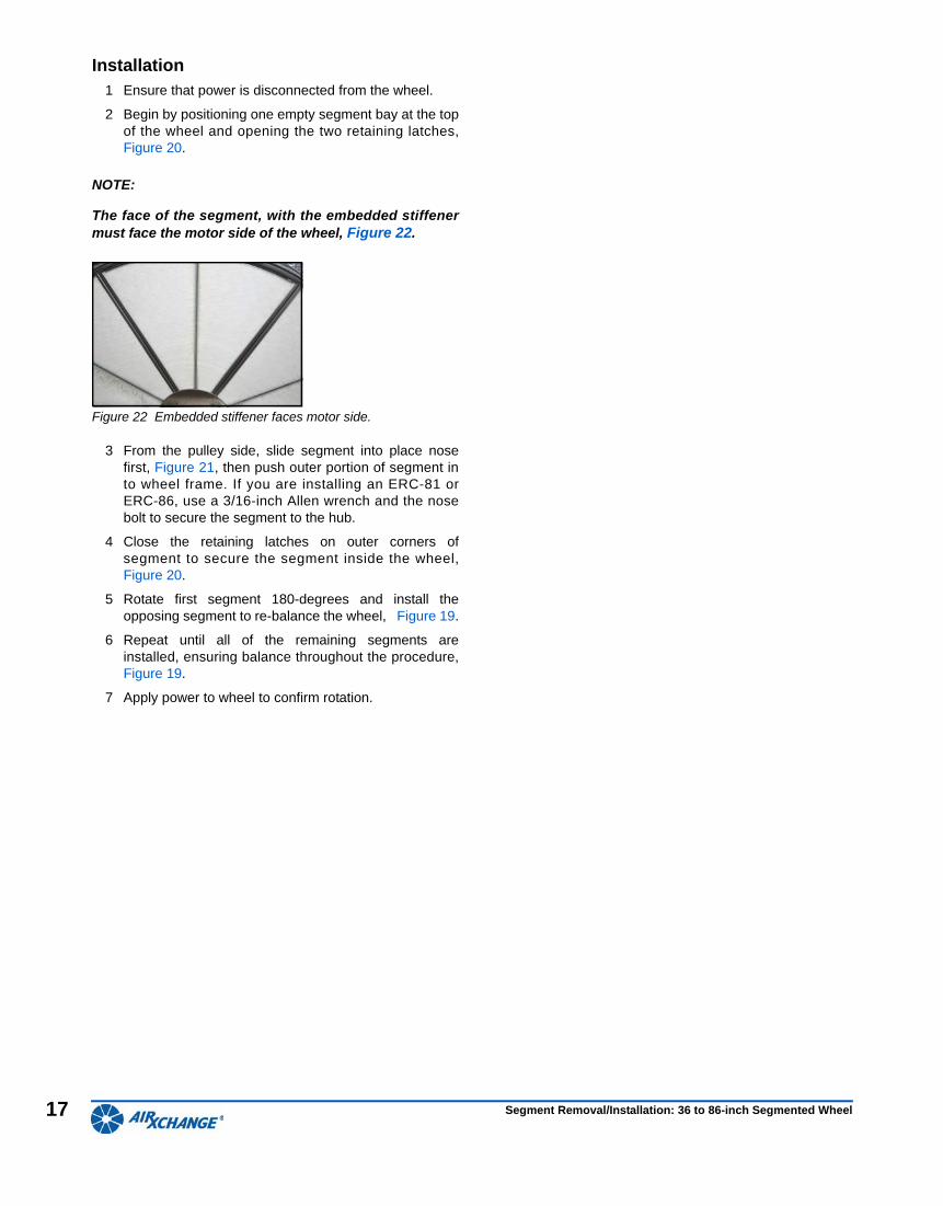
4 Using a flathead screwdriver, unlock and open the twosegment retaining latches, Figure 20, at the outercorners of the segment to be removed.
Figure 20 Release retaining latches following steps 1 and 2 in diagram.
5 For ERC-81 and ERC 86, use a 3/16-inch Allen wrenchto remove the nose bolt securing the segment to thehub plate, Figure 21.
Figure 21 Nose entering hub plate (ERC 81-86 ONLY includes a screw).
6 Remove segment by sliding outer portion of segmentout first before disengaging the nose, Figure 21. Aflathead Screwdriver may be used to aid segmentremoval. Be careful not to bend the segment frame orwheel rim.
7 Once segment is removed, close both latches.WARNING: THE WHEEL IS NOW UNBALANCED.
8 Slowly rotate wheel 180-degrees and remove theopposing segment to re-balance the wheel, Figure 19.
9 Remove the remaining segments by repeating theprevious three steps.
WARNING
An uneven number of segments in the wheel will cause the wheel to accelerate in rotation. Minimize wheel imbalance and unwanted rotation during service by installing or removing opposing segments for even weight distribution, Figure 19. Failure to maintain control of the wheel rotation while removing or installing all segments could cause severe injury to fingers or hands. Always close and secure segment retaining latches before rotating wheel.
WARNING
Before servicing entire HVAC system, turn off the main disconnect to the unit. Use the site-specific Lockout-Tagout out procedure.
Retaining Latch
Segment Removal/Installation: 36 to 86-inch Segmented Wheel
17
Installation1 Ensure that power is disconnected from the wheel.
2 Begin by positioning one empty segment bay at the topof the wheel and opening the two retaining latches,Figure 20.
NOTE:
The face of the segment, with the embedded stiffenermust face the motor side of the wheel, Figure 22.
Figure 22 Embedded stiffener faces motor side.
3 From the pulley side, slide segment into place nosefirst, Figure 21, then push outer portion of segment into wheel frame. If you are installing an ERC-81 orERC-86, use a 3/16-inch Allen wrench and the nosebolt to secure the segment to the hub.
4 Close the retaining latches on outer corners ofsegment to secure the segment inside the wheel,Figure 20.
5 Rotate first segment 180-degrees and install theopposing segment to re-balance the wheel, Figure 19.
6 Repeat until all of the remaining segments areinstalled, ensuring balance throughout the procedure,Figure 19.
7 Apply power to wheel to confirm rotation.
Segment Removal/Installation: 36 to 86-inch Segmented Wheel
18
92 to 110-inch Segmented Wheel
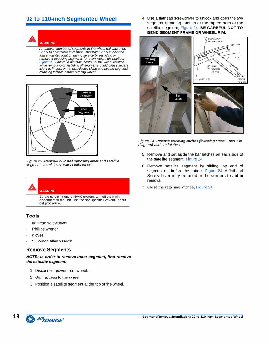
Figure 23 Remove or install opposing inner and satellite segments to minimize wheel imbalance.
Tools• flathead screwdriver
• Phillips wrench
• gloves
• 5/32-inch Allen wrench
Remove SegmentsNOTE: In order to remove inner segment, first removethe satellite segment.
1 Disconnect power from wheel.
2 Gain access to the wheel.
3 Position a satellite segment at the top of the wheel.
4 Use a flathead screwdriver to unlock and open the twosegment retaining latches at the top corners of thesatellite segment, Figure 24. BE CAREFUL NOT TOBEND SEGMENT FRAME OR WHEEL RIM.
Figure 24 Release retaining latches (following steps 1 and 2 in diagram) and bar latches.
5 Remove and set aside the bar latches on each side ofthe satellite segment, Figure 24.
6 Remove satellite segment by sliding top end ofsegment out before the bottom, Figure 24. A flatheadScrewdriver may be used in the corners to aid inremoval.
7 Close the retaining latches, Figure 24.
WARNING
An uneven number of segments in the wheel will cause the wheel to accelerate in rotation. Minimize wheel imbalance and unwanted rotation during service by installing or removing opposing segments for even weight distribution, Figure 23. Failure to maintain control of the wheel rotation while removing or installing all segments could cause severe injury to fingers or hands. Always close and secure segment retaining latches before rotating wheel.
WARNING
Before servicing entire HVAC system, turn off the main disconnect to the unit. Use the site-specific Lockout-Tagout out procedure.
Satellite Segment
Inner Segment
Retaining Latch
Bar Latch
Segment Removal/Installation: 92 to 110-inch Segmented Wheel
19
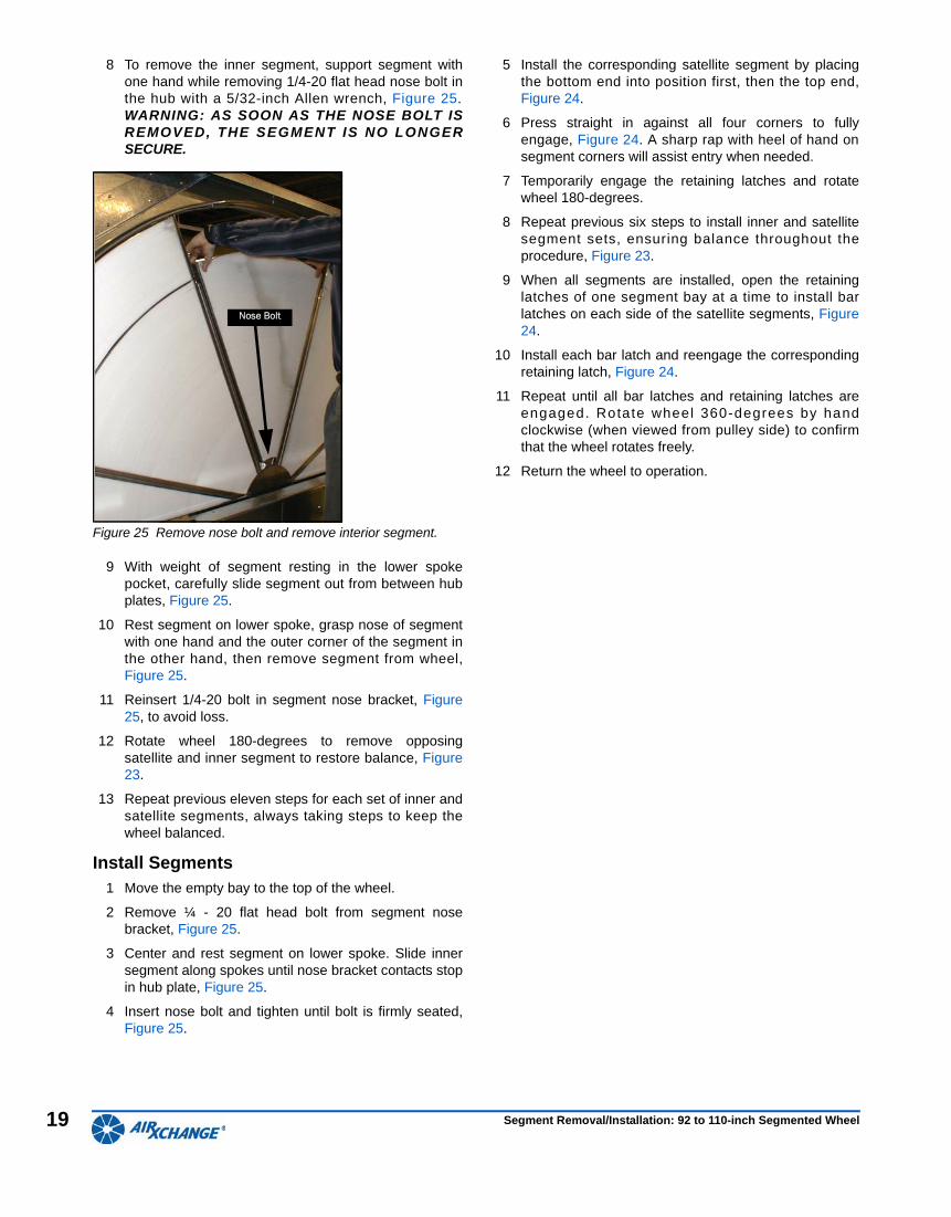
8 To remove the inner segment, support segment withone hand while removing 1/4-20 flat head nose bolt inthe hub with a 5/32-inch Allen wrench, Figure 25.WARNING: AS SOON AS THE NOSE BOLT ISREMOVED, THE SEGMENT IS NO LONGERSECURE.
Figure 25 Remove nose bolt and remove interior segment.
9 With weight of segment resting in the lower spokepocket, carefully slide segment out from between hubplates, Figure 25.
10 Rest segment on lower spoke, grasp nose of segmentwith one hand and the outer corner of the segment inthe other hand, then remove segment from wheel,Figure 25.
11 Reinsert 1/4-20 bolt in segment nose bracket, Figure25, to avoid loss.
12 Rotate wheel 180-degrees to remove opposingsatellite and inner segment to restore balance, Figure23.
13 Repeat previous eleven steps for each set of inner andsatellite segments, always taking steps to keep thewheel balanced.
Install Segments1 Move the empty bay to the top of the wheel.
2 Remove ¼ - 20 flat head bolt from segment nosebracket, Figure 25.
3 Center and rest segment on lower spoke. Slide innersegment along spokes until nose bracket contacts stopin hub plate, Figure 25.
4 Insert nose bolt and tighten until bolt is firmly seated,Figure 25.
5 Install the corresponding satellite segment by placingthe bottom end into position first, then the top end,Figure 24.
6 Press straight in against all four corners to fullyengage, Figure 24. A sharp rap with heel of hand onsegment corners will assist entry when needed.
7 Temporarily engage the retaining latches and rotatewheel 180-degrees.
8 Repeat previous six steps to install inner and satellitesegment sets, ensuring balance throughout theprocedure, Figure 23.
9 When all segments are installed, open the retaininglatches of one segment bay at a time to install barlatches on each side of the satellite segments, Figure24.
10 Install each bar latch and reengage the correspondingretaining latch, Figure 24.
11 Repeat until all bar latches and retaining latches areengaged. Rotate wheel 360-degrees by handclockwise (when viewed from pulley side) to confirmthat the wheel rotates freely.
12 Return the wheel to operation.
Nose Bolt
Segment Removal/Installation: 92 to 110-inch Segmented Wheel
Guide toProducts and Technol-
ogy
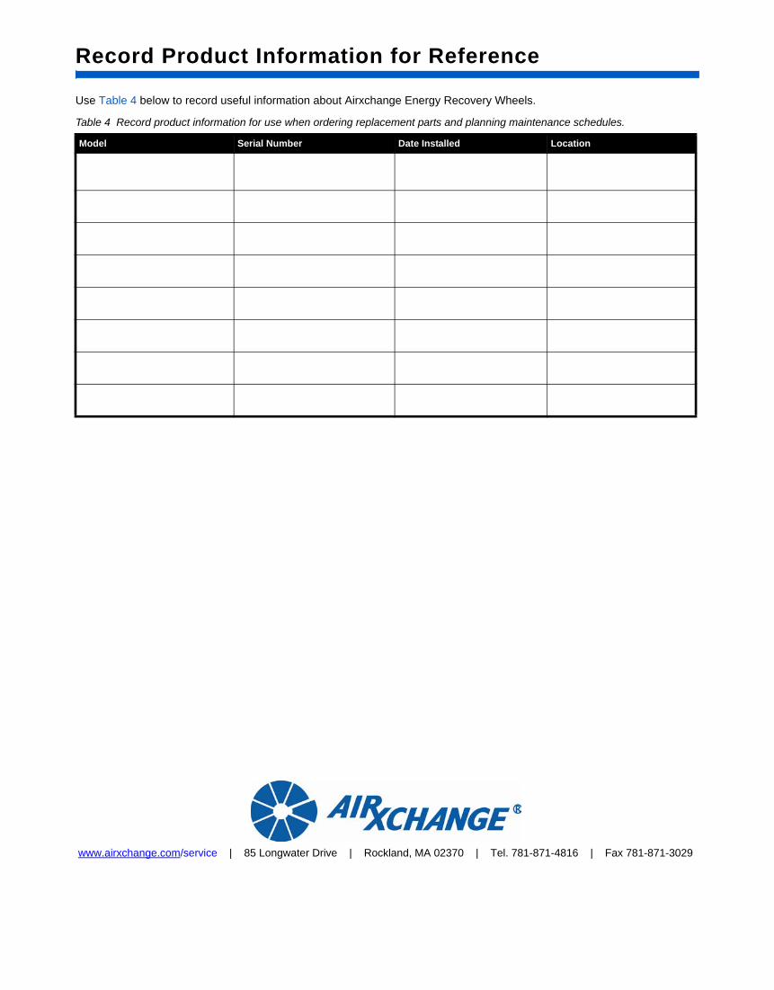
Record Product Information for Reference
Use Table 4 below to record useful information about Airxchange Energy Recovery Wheels.
Table 4 Record product information for use when ordering replacement parts and planning maintenance schedules.
Model Serial Number Date Installed Location
www.airxchange.com/service | 85 Longwater Drive | Rockland, MA 02370 | Tel. 781-871-4816 | Fax 781-871-3029