Embed Size (px)
Citation preview
Volume 40, Number 5, 2020
721
Submitted January 7, 2020; accepted February 28, 2020. ©2020 by Quintessence Publishing Co Inc.
1 Department of Periodontology, Faculty of Dental Medicine, Hebrew University–Hadassah School of Dental Medicine, Jerusalem, Israel.
2 Department of Prosthodontics, Faculty of Dental Medicine, Hebrew University–Hadassah School of Dental Medicine, Jerusalem, Israel.
Correspondence to: Dr Chackartchi Tali, Department of Periodontology, The Hebrew University and Hadassah, Faculty of Dental Medicine, P.O.B. 12272 Jerusalem, 91120 Israel. Email: [email protected]
Guided Implant Placement in Fully Edentulous Patients. The Full Retraction Protocol: Registration Technique to Improve Treatment Outcome
Preoperative planning and implant placement can be optimized using implant planning software followed by the creation of an individual surgical guide. Alongside clinical advantages of using guided surgery, a variability in the accuracy of implant position has been reported. This variability is even more substantial in fully edentulous patients and attributed to errors from intrinsic and extrinsic sources. The aim of this paper is to discuss the potential process errors and present two digital data registration protocols to be implemented in fully edentulous patients. The suggested protocols are aimed to improve accuracy of data acquisition, data superimposition on planning software, and therefore treatment outcome as well. Int J Periodontics Restorative Dent 2020;40:721–729. doi: 10.11607/prd.4807
As life expectancy increases, so does the number of people with edentulous arches. With higher ex-pectations for quality of life, den-tures often no longer meet patient expectations. As a result, many prefer an implant-supported dental prosthesis.1 Patient demand, com-pliance, dexterity, skeletal maxillo-mandibular relations, and residual bone anatomy must be considered when determining the appropriate implant position and type of pros-thesis. In preoperative planning and implant placement, the use of im-plant planning software followed by the creation of individual surgical guides has been shown to improve treatment results.2–8 Nevertheless, variability in the accuracy of guided implant surgery has been reported and attributed to errors from intrin-sic and extrinsic sources.9–11
The data registration needed to compose a digital file for plan-ning includes impressions and 3D imaging of anatomical structures12 (computerized tomography [CT]). Transferring registered information from the patient to the software to create an accurate digital file for implant planning (calibration)12 can be involved with processing errors. This calibration will be even more challenging in edentulous patients due to the absence of reference points, causing inaccuracies in the result (eg, final implant position).13
Tali Chackartchi, DMD1
Tal Neeman, DMD2 Asher Zabrovsky, DMD2
© 2020 BY QUINTESSENCE PUBLISHING CO, INC. PRINTING OF THIS DOCUMENT IS RESTRICTED TO PERSONAL USE ONLY. NO PART MAY BE REPRODUCED OR TRANSMITTED IN ANY FORM WITHOUT WRITTEN PERMISSION FROM THE PUBLISHER.

The International Journal of Periodontics & Restorative Dentistry
722
Data registration using CT with-holds integral errors of hundreds of micrometers up to 1 mm,13,14 de-pending on the scanning technique, parameters, machine in use,15,16 and voxel size. When the voxel size is 0.125 × 0.125 × 0.125 mm, a mini-mal error or resolution of the CT image is at least 0.125 mm.17 3D optical scanning techniques are mainly applied for dental impres-sions during prosthodontic and orthodontic treatment, but are also applied as a method to provide vol-umetric measurements of soft and hard tissues.18,19 The scanning tech-nique and the scanner in use will have an impact on the accuracy of intraoral scanning, but in most cases scanning resolution will be 10 to 20 mm and up to 0.1 mm. Being more accurate and minimally invasive, in-
traoral scanning should replace CT scanning whenever possible.
The aim of this paper is to pres-ent two alternative digital data reg-istration protocols, replacing one CT scan (producing a DICOM file) with an intraoral scan (producing an STL [standard tessellation language] file) in fully edentulous patients. This will improve the accuracy of data acquisition, data superimposition on planning software, and therefore treatment outcome as well.
Digital Registration Protocols
In treatment plans including implant surgery on a fully edentulous pa-tient, the following diagnostic re-cords should be obtained for the two protocols described.
Full Retraction Protocol
Impressions/Intraoral ScanningA dynamic impression of the patient is taken in the same way as for a full denture. Since the template/guide will be supported on the outline of the soft tissues in most fully eden-tulous cases, it is essential to regis-ter the palate in the maxilla and the retromolar pad in the mandible. A working model is created (cast or printed) (Fig 1). The working model will set the base to make a wax-up.
Model and Wax-up ScanningUsing a lab scanner (eg, 3Shape E4), the working model carrying the wax-up is scanned (Fig 2a). This cre-ates the first STL file. Keeping the model in the same position in the scanner, the wax-up is removed, and
Fig 1 To create a proper file for case plan-ning, (a) a working model and (b) a wax-up are required. The palate in the maxilla and the retromolar pad in the mandible are important anatomical structures to be registered. A validated wax-up is prepared and is compatible to the functional and esthetic needs of the patient.
a b
Fig 2 The (a) working model and (b) wax-up are scanned in a laboratory scanner. The working model carrying the wax-up is scanned to create the first STL file. Keeping the model in the same position in the scan-ner, the wax-up is removed, and the model is scanned alone to create the second STL. The two scans should be done in the same orientation and direction (coordinates).
a b
© 2020 BY QUINTESSENCE PUBLISHING CO, INC. PRINTING OF THIS DOCUMENT IS RESTRICTED TO PERSONAL USE ONLY. NO PART MAY BE REPRODUCED OR TRANSMITTED IN ANY FORM WITHOUT WRITTEN PERMISSION FROM THE PUBLISHER.

Volume 40, Number 5, 2020
723
the model is scanned alone (Fig 2b) to create a second STL file. It is im-portant not to change the posi-tion of the model in the scanner between the first and the second scans to allow an automatic calibra-tion of the two scans (one on top of the other) when uploaded to the software (MSoft, TechMed 3D).
CBCT ScanThe patient is then referred to CBCT scan. The CT image is presented in degrees of gray according to its Hounsfield units (HUs). HUs are de-fined as linear transformations of measured x-ray attenuation coeffi-cients of a material with reference to water (0HU).20 Air will be represent-
ed as black, measured as (–1,000) HU, and metal will be presented as white, measured as (+1,000) HU. These units can provide an accurate absolute density for the type of tis-sue described. In the full retraction protocol, retractors or cotton rolls are used to reflect the buccal muco-sa, tongue, and lips from the gingiva during scanning (Fig 3), creating an air chamber around the soft tissues of the patient. This enables clinicians to discern and outline the borders of the soft tissues overlaying the bone (Fig 4). The soft tissue outline will be used as reference to super-impose the scanned working model and wax-up on the CT image.
Software Data SuperimpositionThe DICOM files are uploaded to the software. The STLs of the scanned model and the scanned wax-up are calibrated on the CT image. In edentulous cases, there are no teeth or rigid components to serve as a reference for calibration. The soft tissue outline revealed by the con-trast from tissue separation will be used as a reference for overlapping the CT and STL images (Fig 5).
At this stage, the digital file is ready for implant planning (Fig 6), considering tissue volume and the planned restoration (“top-down planning”). A surgical guide will be virtually planned according to the implant position, surgical plan, and
Fig 3 During CT scanning, the soft tissues (lips, cheeks, and tongue) are reflected from the gingiva to create an air chamber around the soft tissues. This will enable a clear visualization of the gingival outline.
Fig 4 The soft tissue outline, revealed due to the contrast created by tissue separation, serves as numerous points of reference for CT and STL overlapping.
Fig 5 Calibration of STL files over the CT image is done by following the soft tissue outline.
© 2020 BY QUINTESSENCE PUBLISHING CO, INC. PRINTING OF THIS DOCUMENT IS RESTRICTED TO PERSONAL USE ONLY. NO PART MAY BE REPRODUCED OR TRANSMITTED IN ANY FORM WITHOUT WRITTEN PERMISSION FROM THE PUBLISHER.

The International Journal of Periodontics & Restorative Dentistry
724
tissue morphology (Fig 7a). The STL of the designed surgical guide will then be 3D-printed and used dur-ing surgery (Fig 7b).
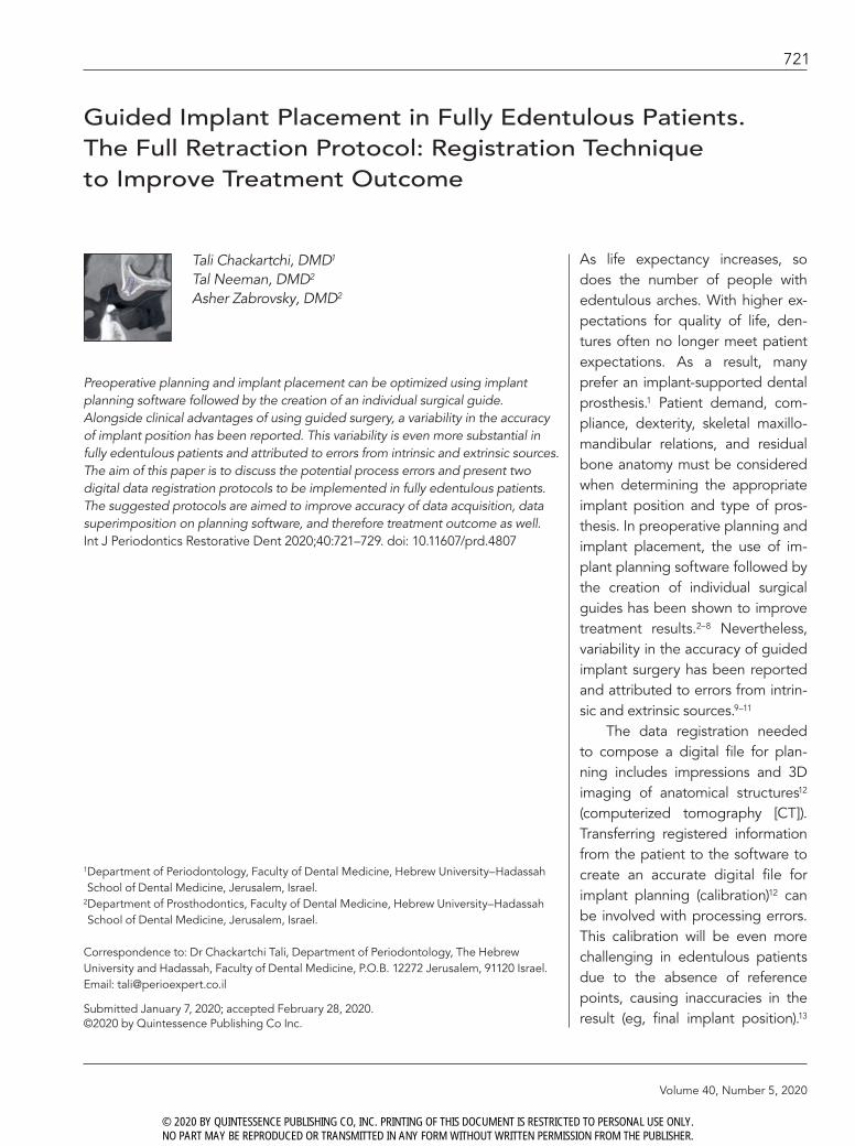
During surgery, the guide is supported by the soft tissues with hand fixation to prevent its shift dur-ing the drilling stage (Figs 7c and
7d). In the presented case (Fig 7c), after the insertion of the posterior implants using the MGuide drilling system (MIS Implants Technologies), it was used for further fixation by keeping the insertion tools in the guide during drilling of anterior im-plants. Correct registration of data
and passive drilling will enable a predictable final implant position (Figs 7e to 7g, Table 1), compatible with previously reported results in cases of fully edentulous patients.
In cases where the patient can-not hold the retractors or cotton rolls due to physical problems, a
Fig 6 After superimposing the STLs of the impression and the wax-up on the DICOM image, the digital file is ready for implant planning, considering tissue volume and the planned restoration (“top-down planning”).
Fig 7a A surgical guide will be virtually planned according to implant position, considering the need for tissue support to stabilize the guide during drilling.
Fig 7b The STL of the designed surgical guide will be 3D printed (left), becoming a physi-cal instrument to be used during surgery (right).
Fig 7c The posterior implants were pre-pared and placed first. Insertion tools were used for additional guide stabilization dur-ing placement of the anterior implants.
© 2020 BY QUINTESSENCE PUBLISHING CO, INC. PRINTING OF THIS DOCUMENT IS RESTRICTED TO PERSONAL USE ONLY. NO PART MAY BE REPRODUCED OR TRANSMITTED IN ANY FORM WITHOUT WRITTEN PERMISSION FROM THE PUBLISHER.
Volume 40, Number 5, 2020
725
Fig 7e Five implants were placed. One was intended to be immediately loaded together with an orthodontic temporary an-chorage device to prevent force implemen-tation from the denture to the submerged implants during the osseointegration period.
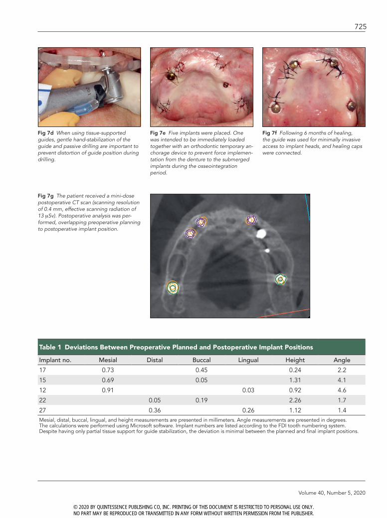
Table 1 Deviations Between Preoperative Planned and Postoperative Implant Positions
Implant no. Mesial Distal Buccal Lingual Height Angle
17 0.73 0.45 0.24 2.2
15 0.69 0.05 1.31 4.1
12 0.91 0.03 0.92 4.6
22 0.05 0.19 2.26 1.7
27 0.36 0.26 1.12 1.4Mesial, distal, buccal, lingual, and height measurements are presented in millimeters. Angle measurements are presented in degrees. The calculations were performed using Microsoft software. Implant numbers are listed according to the FDI tooth numbering system. Despite having only partial tissue support for guide stabilization, the deviation is minimal between the planned and final implant positions.
Fig 7d When using tissue-supported guides, gentle hand-stabilization of the guide and passive drilling are important to prevent distortion of guide position during drilling.
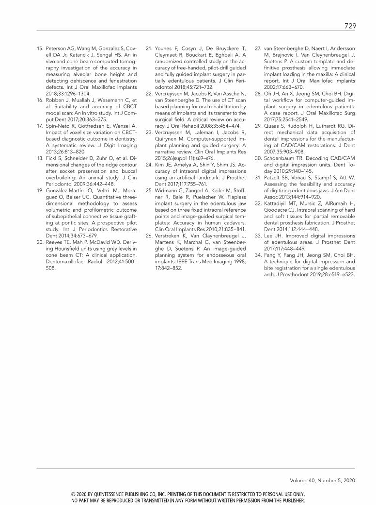
Fig 7f Following 6 months of healing, the guide was used for minimally invasive access to implant heads, and healing caps were connected.
Fig 7g The patient received a mini-dose postoperative CT scan (scanning resolution of 0.4 mm, effective scanning radiation of 13 mSv). Postoperative analysis was per-formed, overlapping preoperative planning to postoperative implant position.
© 2020 BY QUINTESSENCE PUBLISHING CO, INC. PRINTING OF THIS DOCUMENT IS RESTRICTED TO PERSONAL USE ONLY. NO PART MAY BE REPRODUCED OR TRANSMITTED IN ANY FORM WITHOUT WRITTEN PERMISSION FROM THE PUBLISHER.

The International Journal of Periodontics & Restorative Dentistry
726
marked gag reflex, or a very re-sorbed mandible (in which the floor of the mouth is overlaying the ridge), there is a risk for inaccurate soft tissue registration in the CBCT scan. For these cases, the authors
suggest the beads protocol. This protocol uses only one CBCT scan, keeping accuracy in data registra-tion. The process is described as follows.
Beads Protocol (Revised Dual Scan Protocol)
Impressions/Intraoral ScanningThis process is similar to the one de scribed for the previous protocol. A working model is created (cast or printed) with three indices on the base. A wax-up is created and verified in the mouth of the patient (Fig 8).
Model and Wax-up ScanningPrior to scanning, the model will be prepared by gluing four or five radi-opaque markers (Fig 8), such as commercial beads with a standard size and homogenous radiopacity (Visionmark V-25 [Suremark] or custom-made gutta percha balls). Using a laboratory scanner (3Shape E4), the working model carrying the wax-up is scanned producing an STL file. Keeping the model position in the scanner, the wax-up is re-moved, and the model is scanned separately to create a second STL file. The flanges of the wax-up are
Fig 8 Four or five radiopaque beads are glued to the plaster base. The base with the beads carrying the wax-up is scanned in a table scanner.
Fig 9 After the first scan (described in Fig 6), the radiopaque beads are integrated into the denture (arrows). This denture will be inserted in the patient’s mouth to be used and therefore scanned during the CBCT.
Fig 10 The radiopaque beads will be visible in the CT image. This will enable calibration of the wax-up and cast model STL files on the CT image.
© 2020 BY QUINTESSENCE PUBLISHING CO, INC. PRINTING OF THIS DOCUMENT IS RESTRICTED TO PERSONAL USE ONLY. NO PART MAY BE REPRODUCED OR TRANSMITTED IN ANY FORM WITHOUT WRITTEN PERMISSION FROM THE PUBLISHER.

Volume 40, Number 5, 2020
727
then elongated to cover and inte-grate the beads out of the model and into the denture (Fig 9). This version of the wax-up is then given to the patient to wear during the CBCT scan.
CBCT ScanThe patient wears the wax-up with the radiopaque markers during the scan. The base of the wax-up should be very well adapted to the soft tis-sues of the patient, creating equal pressure on the soft tissues. The acrylic material used for the radio-graphic stent may not be totally ra-diolucent, causing scatter that affects the soft tissue visualization. To im-prove visualization of possible cali-bration errors, the scan is performed the same as in the full retraction pro-tocol (with retraction of soft tissues and the tongue, as described earlier).
Software Data SuperimpositionThe DICOM files are uploaded on the software. The STLs of the scanned working model and the scanned wax-up are calibrated with the CT image. In this protocol, the calibration of the model on the CT is possible by superimposing the ra-diopaque markers from the CT and STL images (Fig 10).
Discussion
Computer-guided implant surgery offers the ability to plan “top-down” implant position, maximize accu-racy, take into consideration hard tissue anatomy and soft tissue vol-ume, and identify the location of future prostheses. Guided surgery
is well established to be more pre-dictable in implant positioning than free-hand implant placement,21 but deviations and errors can still be expected.22 The process of data registration and superimposition of the registered information in layers in the software is essential to cre-ate a digital platform for treatment planning. Superimposing data com-prises potential errors that might in-fluence final implant position.13
Remaining teeth are used as compatible areas for matching im-ages produced by the scanners (CBCT and table scanner) to create a digital file for planning.13,23
When the remaining teeth are insufficient or absent (as in fully edentulous cases), the accuracy of image superimposition decreases dramatically. In patients with ex-tensive tooth loss, the use of addi-tional markers attempts to increase the accuracy in matching CBCT and digital surface scan images.24,25 The most frequent protocol for data registration and calibration in fully edentulous patients is the dual scan protocol suggested by Verstreken et al26 followed by van Steenberghe et al.27 This protocol is based on superimpositioning two DICOM files: one of the patient wearing a denture with integrated radiopaque markers and the second of the denture only. Radiopaque markers used for calibration may create a scattered image on the CT, casting doubt on the ability to perform a precise match. Over the years, other protocols were introduced. Oh et al28 suggested inserting additional resin markers on the palatal gingiva prior to CBCT scanning, increasing
the matching points and thereby enhancing the registration accuracy of CBCT and digital surface scan data. Widmann et al25 demonstrat-ed the use of implants with ball at-tachments to increase the number of reference points for image super-imposition in edentulous arches and concluded that a fixed reference im-proves registration accuracy.
The full retraction protocol pre-sented is a nonsurgical, inexpensive, and easily applicable protocol to im-prove accuracy in data registration. Data superimposition is based on the visualization of the soft tissues, creating numerous reference points for image matching. This protocol reduces the use of CT scans and DI-COM data. Additional information of the prosthetic wax-up is regis-tered using an STL file that is more accurate. Intraoral digital scanning has allowed clinicians to directly ac-quire data from the mouth without needing to make a conventional impression and pour a cast.29,30 Sev-eral reports have focused on the feasibility and accuracy of intraoral digital scans for complete arches. However, few published studies have evaluated direct digital scans of edentulous arches using intra-oral scanners due to the difficulty in scanning edentulous sites that are smooth and devoid of features.31,32 The stitching process can be faulty, especially in the palatal area.31 Sev-eral techniques were suggested to overcome these difficulties and en-able a complete, accurate scan.33,34
The beads protocol is a revi-sion of the dual scan protocol, pro-viding another possible option for data registration with only one CT
© 2020 BY QUINTESSENCE PUBLISHING CO, INC. PRINTING OF THIS DOCUMENT IS RESTRICTED TO PERSONAL USE ONLY. NO PART MAY BE REPRODUCED OR TRANSMITTED IN ANY FORM WITHOUT WRITTEN PERMISSION FROM THE PUBLISHER.

The International Journal of Periodontics & Restorative Dentistry
728
scan. This protocol still holds the disadvantage of limited points of reference for calibration of the CT image and the STL files, since pri-mary calibration is done according to radiopaque markers. The addi-tion of the full retraction protocol will improve the ability to diagnose possible mismatches (Fig 11).
Conclusions
Computer-supported implant plan-ning and guided surgery will be-come a standard of care to maximize treatment results. To achieve an ac-curate and safe treatment result, care should be taken in all stages of the workflow, especially during data acquisition, to create a proper digi-tal file for implant planning. In fully edentulous cases, there are limited points of reference for superimpos-ing layers of information on the software. Therefore, data acquisi-tion should be performed accord-ing to specific protocols, aiming to maximizing the points of reference.
Acknowledgments
The authors would like to acknowledge Mr Louis Wostein and Mr Salo Kegen for their technical support. The authors declare no conflicts of interest.
References
1. Carlsson GE, Lindquist LW. Ten-year longitudinal study of masticatory func-tion in edentulous patients treated with fixed complete dentures on osseoin-tegrated implants. Int J Prosthodont 1994;7:448–453.
2. Jabero M, Sarment DP. Advanced surgi-cal guidance technology: A review. Im-plant Dent 2006;15:135–142.
3. Besimo CE, Lambrecht JT, Guindy JS. Accuracy of implant treatment planning utilizing template-guided reformatted computed tomography. Dentomaxillo-fac Radiol 2000;29:46–51.
4. Gaggl A, Schultes G, Kärcher H. Naviga-tional precision of drilling tools prevent-ing damage to the mandibular canal. J Craniomaxillofac Surg 2001;29:271–275.
5. Widmann G, Bale RJ. Accuracy in computer-aided implant surgery—A review. Int J Oral Maxillofac Implants 2006;21:305–313.
6. Jacobs R, Adriensens A, Verstreken K, Suetens P, van Steenberghe D. Predict-ability of a three-dimensional planning system for oral implant surgery. Dento-maxillofac Radiol 1999;28:105–111.
7. Gulati M, Anand V, Salaria SK, Jain N, Gupta S. Computerized implant-dentistry: Advances toward automation. J Indian Soc Periodontol 2015;19:5–10.
8. Engelke W, Capobianco M. Flapless sinus floor augmentation using endo-scopy combined with CT scan-designed surgical templates: Method and report of 6 consecutive cases. Int J Oral Maxil-lofac Implants 2005;20:891–897.
9. Cassetta M, Di Mambro A, Giansanti M, Stefanelli LV, Barbato E. How does an error in positioning the template af-fect the accuracy of implants inserted using a single fixed mucosa-supported stereolithographic surgical guide? Int J Oral Maxillofac Surg 2014;43:85–92.
10. Cassetta M, Di Mambro A, Giansanti M, Stefanelli LV, Cavallini C. The intrin-sic error of a stereolithographic surgical template in implant guided surgery. Int J Oral Maxillofac Surg 2013;42:264–275.
11. Van Assche N, Quirynen M. Tolerance within a surgical guide. Clin Oral Im-plants Res 2010;21:455–458.
12. Miller RJ, Bier J. Surgical navigation in oral implantology. Implant Dent 2006; 15:41–47.
13. Flügge T, Derksen W, Te Poel J, Hassan B, Nelson K, Wismeijer D. Registration of cone beam computed tomography data and intraoral surface scans—A prerequisite for guided implant surgery with CAD/CAM drilling guides. Clin Oral Implants Res 2017;28:1113–1118.
14. Nkenke E, Zachow S, Benz M, et al. Fu-sion of computed tomography data and optical 3D images of the dentition for streak artefact correction in the simu-lation of orthognathic surgery. Dento-maxillofac Radiol 2004;33:226–232.
Fig 11 The addition of the full retraction protocol will improve the ability to diagnose possible mismatches of STL files on the DICOM files, including cases in which radiopaque markers are in use. The arrows point to the deviation in position between the gray CT image and the green outline of the STL scan.
© 2020 BY QUINTESSENCE PUBLISHING CO, INC. PRINTING OF THIS DOCUMENT IS RESTRICTED TO PERSONAL USE ONLY. NO PART MAY BE REPRODUCED OR TRANSMITTED IN ANY FORM WITHOUT WRITTEN PERMISSION FROM THE PUBLISHER.
Volume 40, Number 5, 2020
729
15. Peterson AG, Wang M, Gonzalez S, Cov-ell DA Jr, Katancik J, Sehgal HS. An in vivo and cone beam computed tomog-raphy investigation of the accuracy in measuring alveolar bone height and detecting dehiscence and fenestration defects. Int J Oral Maxillofac Implants 2018;33:1296–1304.
16. Robben J, Muallah J, Wesemann C, et al. Suitability and accuracy of CBCT model scan: An in vitro study. Int J Com-put Dent 2017;20:363–375.
17. Spin-Neto R, Gotfredsen E, Wenzel A. Impact of voxel size variation on CBCT-based diagnostic outcome in dentistry: A systematic review. J Digit Imaging 2013;26:813–820.
18. Fickl S, Schneider D, Zuhr O, et al. Di-mensional changes of the ridge contour after socket preservation and buccal overbuilding: An animal study. J Clin Periodontol 2009;36:442–448.
19. González-Martín O, Veltri M, Morá-guez O, Belser UC. Quantitative three-dimensional methodology to assess volumetric and profilometric outcome of subepithelial connective tissue graft-ing at pontic sites: A prospective pilot study. Int J Periodontics Restorative Dent 2014;34:673–679.
20. Reeves TE, Mah P, McDavid WD. Deriv-ing Hounsfield units using grey levels in cone beam CT: A clinical application. Dentomaxillofac Radiol 2012;41:500–508.
21. Younes F, Cosyn J, De Bruyckere T, Cleymaet R, Bouckart E, Eghbali A. A randomized controlled study on the ac-curacy of free-handed, pilot-drill guided and fully guided implant surgery in par-tially edentulous patients. J Clin Peri-odontol 2018;45:721–732.
22. Vercruyssen M, Jacobs R, Van Assche N, van Steenberghe D. The use of CT scan based planning for oral rehabilitation by means of implants and its transfer to the surgical field: A critical review on accu-racy. J Oral Rehabil 2008;35:454–474.
23. Vercruyssen M, Laleman I, Jacobs R, Quirynen M. Computer-supported im-plant planning and guided surgery: A narrative review. Clin Oral Implants Res 2015;26(suppl 11):s69–s76.
24. Kim JE, Amelya A, Shin Y, Shim JS. Ac-curacy of intraoral digital impressions using an artificial landmark. J Prosthet Dent 2017;117:755–761.
25. Widmann G, Zangerl A, Keiler M, Stoff-ner R, Bale R, Puelacher W. Flapless implant surgery in the edentulous jaw based on three fixed intraoral reference points and image-guided surgical tem-plates: Accuracy in human cadavers. Clin Oral Implants Res 2010;21:835–841.
26. Verstreken K, Van Claynenbreugel J, Martens K, Marchal G, van Steenber-ghe D, Suetens P. An image-guided planning system for endosseous oral implants. IEEE Trans Med Imaging 1998; 17:842–852.
27. van Steenberghe D, Naert I, Andersson M, Brajnovic I, Van Cleynenbreugel J, Suetens P. A custom template and de-finitive prosthesis allowing immediate implant loading in the maxilla: A clinical report. Int J Oral Maxillofac Implants 2002;17:663–670.
28. Oh JH, An X, Jeong SM, Choi BH. Digi-tal workflow for computer-guided im-plant surgery in edentulous patients: A case report. J Oral Maxillofac Surg 2017;75:2541–2549.
29. Quaas S, Rudolph H, Luthardt RG. Di-rect mechanical data acquisition of dental impressions for the manufactur-ing of CAD/CAM restorations. J Dent 2007;35:903–908.
30. Schoenbaum TR. Decoding CAD/CAM and digital impression units. Dent To-day 2010;29:140–145.
31. Patzelt SB, Vonau S, Stampf S, Att W. Assessing the feasibility and accuracy of digitizing edentulous jaws. J Am Dent Assoc 2013;144:914–920.
32. Kattadiyil MT, Mursic Z, AlRumaih H, Goodacre CJ. Intraoral scanning of hard and soft tissues for partial removable dental prosthesis fabrication. J Prosthet Dent 2014;112:444–448.
33. Lee JH. Improved digital impressions of edentulous areas. J Prosthet Dent 2017;117:448–449.
34. Fang Y, Fang JH, Jeong SM, Choi BH. A technique for digital impression and bite registration for a single edentulous arch. J Prosthodont 2019;28:e519–e523.
© 2020 BY QUINTESSENCE PUBLISHING CO, INC. PRINTING OF THIS DOCUMENT IS RESTRICTED TO PERSONAL USE ONLY. NO PART MAY BE REPRODUCED OR TRANSMITTED IN ANY FORM WITHOUT WRITTEN PERMISSION FROM THE PUBLISHER.

Copyright of International Journal of Periodontics & Restorative Dentistry is the property ofQuintessence Publishing Company Inc. and its content may not be copied or emailed tomultiple sites or posted to a listserv without the copyright holder's express written permission.However, users may print, download, or email articles for individual use.