Embed Size (px)
Citation preview
See discussions, stats, and author profiles for this publication at: https://www.researchgate.net/publication/320280775
Guideline for Earthing of Buildings and Industrial plants
Book · October 2017
CITATIONS
0READS
6,943
1 author:
Some of the authors of this publication are also working on these related projects:
Paralleling distributed generators and solar power View project
Earthing View project
Paneendra Kumar Bl
VKES.org
3 PUBLICATIONS 0 CITATIONS
SEE PROFILE
All content following this page was uploaded by Paneendra Kumar Bl on 09 October 2017.
The user has requested enhancement of the downloaded file.
Page 1 No 213, 13th Main RBI Layout JP Nagar 7th Phase, Bangalore 560078. Mobile: 91-9880784082,
Email: [email protected], [email protected], www.vkes.org
VKES Vidyuth Kanti Engineering Services
Page 2 No 213, 13th Main RBI Layout JP Nagar 7th Phase, Bangalore 560078. Mobile: 91-9880784082,
Email: [email protected], [email protected], www.vkes.org
VKES Vidyuth Kanti Engineering Services
Contents Guideline for Earthing of Building and Industrial plants ......................................................................... 5
1.0 Scope ........................................................................................................................................... 5
2.0 Exclusions .................................................................................................................................... 5
3.0 Reference Standard .................................................................................................................... 5
4.0 What is the function of earthing ................................................................................................. 5
5.0 What is the difference between Earthing of Substation and Building ....................................... 5
6.0 Basic requirement before starting the earthing design .............................................................. 5
7.0 Methodology of earthing design................................................................................................. 6
8.0 Objective of earthing design ....................................................................................................... 7
9.0 Fault current calculation results ................................................................................................. 7
10.0 Material of earthing conductor................................................................................................... 7
11.0 Earthing conductor sizing ............................................................................................................ 7
12.0 Current density limitation at electrode ...................................................................................... 8
13.0 Minimum dimensions of conductors .......................................................................................... 9
14.0 Corrosion ..................................................................................................................................... 9
15.0 Source earthing ......................................................................................................................... 10
15.1 One Generator in isolation........................................................................................................ 10
15.2 Many Generator in isolation ..................................................................................................... 10
15.3 One Generator parallel with utility ........................................................................................... 10
15.4 Many Generator parallel with utility ........................................................................................ 10
15.5 Many Transformers ................................................................................................................... 10
15.6 Transformer neutral earthing ................................................................................................... 11
15.7 Earthing of UPS neutral ............................................................................................................. 11
16.0 Types of earthing based on resistance ..................................................................................... 11
16.1 Solidly grounded system ........................................................................................................... 11
16.2 Unearthed or ungrounded system ........................................................................................... 11
16.3 Reactance earthed system and resonant earthed system ....................................................... 11
16.4 Resistance earthed system ....................................................................................................... 11
16.5 Types of Resistance earthed system ......................................................................................... 12
17.0 Different types of LV earthing system (BS 7430) ...................................................................... 13
17.1 Earth Loop Impedance .............................................................................................................. 14
18.0 Potential gradient around the earth electrode ........................................................................ 15
Page 3 No 213, 13th Main RBI Layout JP Nagar 7th Phase, Bangalore 560078. Mobile: 91-9880784082,
Email: [email protected], [email protected], www.vkes.org
VKES Vidyuth Kanti Engineering Services
19.0 Earth Resistivity measurement ................................................................................................. 15
20.0 Resistance of earthing system .................................................................................................. 15
21.0 Measurement of electrode resistance ...................................................................................... 16
22.0 What all needs to be earthed ................................................................................................... 16
22.1 Source Neutral earthing ............................................................................................................ 16
22.2 Cable Armour earthing .............................................................................................................. 16
22.3 Cable Tray earthing ................................................................................................................... 16
22.4 Electrical Panel and Distribution boards earthing .................................................................... 16
22.5 Junction Box earthing ............................................................................................................... 17
22.6 Motor and Push button station earthing .................................................................................. 17
22.7 Lighting poles and fixtures earthing.......................................................................................... 17
22.8 Tanks, Vessels, Piping earthing ................................................................................................. 17
22.9 Package equipments earthing................................................................................................... 17
22.10 Lightning Protection system earthing ................................................................................... 17
22.11 Electronic equipments earthing system ............................................................................... 17
22.12 Earthing of utility pipes ......................................................................................................... 18
22.13 Earthing of steel reinforced bars of structures and buildings .............................................. 18
23.0 Earthing Schematic ................................................................................................................... 19
24.0 Types of Electrodes and their resistances ................................................................................ 20
24.1 Resistance of Plate electrode .................................................................................................... 20
24.2 Resistance of Rod or Pipe electrode ......................................................................................... 21
24.3 Resistance of Rod electrodes in parallel ................................................................................... 21
24.4 Variation of resistance of electrode due to length and diameter of the rod (Table 5 and
Table 6) ................................................................................................................................................. 22
24.5 Resistance of straight Strip ....................................................................................................... 23
24.6 Resistance of Mesh ................................................................................................................... 23
24.7 Resistivity of electrodes encased in Low resistivity materials .................................................. 23
24.8 Earthing of steel reinforced concrete foundations ................................................................... 23
25.0 Treated earth electrodes .......................................................................................................... 23
26.0 Auxiliary earth grid .................................................................................................................... 24
27.0 Typical Earthing Layout of LV MV Substations .......................................................................... 25
28.0 Layout Requirement ................................................................................................................. 26
28.1 Spacing between electrodes ..................................................................................................... 26
Page 4 No 213, 13th Main RBI Layout JP Nagar 7th Phase, Bangalore 560078. Mobile: 91-9880784082,
Email: [email protected], [email protected], www.vkes.org
VKES Vidyuth Kanti Engineering Services
28.2 Distance between electrode and building wall ......................................................................... 26
28.3 Depth of horizontal conductor or connecting conductors ....................................................... 26
29.0 Stray Currents ........................................................................................................................... 26
30.0 Common mode noise ................................................................................................................ 26
31.0 Typical Calculation of Earth electrode resistance of substation ............................................... 26
31.1 Resistance of Rod electrodes in parallel (BS 7430) ................................................................... 26
31.2 Resistance of straight Strip (BS 7430) ...................................................................................... 26
31.3 Resistance of Mesh (BS 7430) ................................................................................................... 26
32.0 Type of joints ............................................................................................................................. 27
33.0 Recommended dimensions of earthing Conductor (Table 7) ................................................... 27
34.0 Typical Earthing design of Oil and Gas installation ................................................................... 28
34.1 Calculation and steps for typical Oil and gas installation earthing design ............................... 30
35.0 Reference .................................................................................................................................. 34
Page 5 No 213, 13th Main RBI Layout JP Nagar 7th Phase, Bangalore 560078. Mobile: 91-9880784082,
Email: [email protected], [email protected], www.vkes.org
VKES Vidyuth Kanti Engineering Services
Guideline for Earthing of Buildings and Industrial plants
1.0 Scope
This guide covers the earthing of Domestic, Commercial buildings and Industrial Plants.
These can be constructed by concrete or steel frame or both. The industrial plants means
outdoor areas in Industries like refinery, power plant, Cement plant, steel plant etc.
2.0 Exclusions
Substation, Generator neutral, Transmission line, Telecommunication facility, Hospital,
Mines, Offshore, Ships, Portable equipment internal earthing, Data centre, DC system
earthing, NGR NGT sizing, Lightning protection system design, static charges protection and
EMC protection.
3.0 Reference Standard
This guide is prepared after referring to the following standards: BS 7430, IEEE 142, EN
50522 and IS 3043. Readers should note that this guide is supplementary to these
standards. Readers have to refer the standards before designing a system.
4.0 What is the function of earthing
Basically earthing is done to protect Human beings from getting electrocuted and to protect
Overvoltage in Electrical equipment, which may lead to insulation failure.
5.0 What is the difference between Earthing of Substation and Building
In order to protect people, the current through human body has to be kept lower than certain
values. Current through the body depends on the voltage across the body and the body
resistance. In case of substation Earthing design, the voltage seen by the body is calculated
and compared with tolerable values. Whereas in the earthing design of building and
industries touch and step voltage calculation are not carried out. The total earth grid
resistance has to be maintained below certain prescribed value and earth loop impedance
has to be kept low. In a substation the human beings working are electrical professional,
they are trained people or they are supervised by someone. In industries also there are
trained people but in case of domestic and commercial buildings, non electrical non
supervised person may get electrocuted. In a substation the rise in ground potential is due to
the flow of part of fault current through the earth and earth grid. In buildings and industries
the rise in potential is due to the flow of a part of the fault current through the earth (major
part of fault current flows through earth loop impedance).
6.0 Basic requirement before starting the earthing design
Before stating the design the designer should have the following details: Earth resistivity of the site (CL 19.0) Fault current calculation results (CL 9.0) Details about the regulation Select the material of earthing conductor (CL 14.0) Earthing conductor Sizing (Refer CL 10.0) Layout of the industry/Site/Plant, (Refer CL 23.0) Type of source earthing to be used (Refer CL 17.0) Resistance of earthing system to be achieved (CL 24.0)
Page 6 No 213, 13th Main RBI Layout JP Nagar 7th Phase, Bangalore 560078. Mobile: 91-9880784082, Email: [email protected], [email protected], www.vkes.org
VKES Vidyuth Kanti Engineering Services
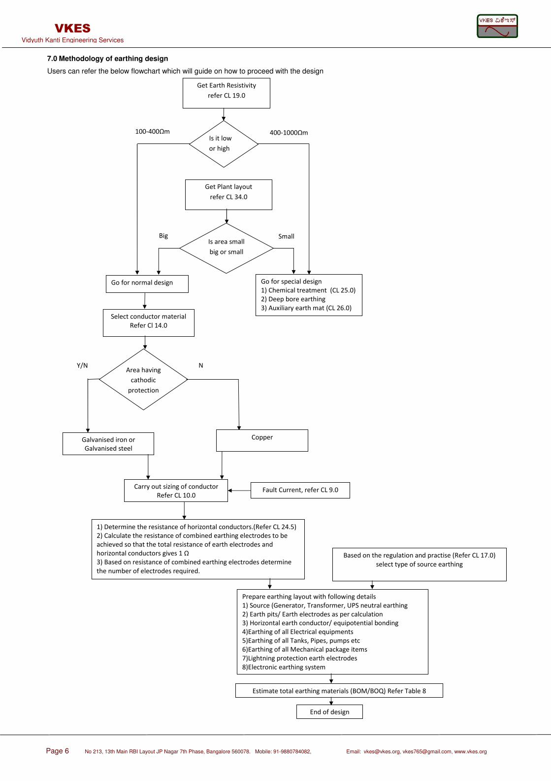
7.0 Methodology of earthing design
Users can refer the below flowchart which will guide on how to proceed with the design
Get Earth Resistivity
refer CL 19.0
Is it low
or high
Get Plant layout
refer CL 34.0
Is area small
big or small
Go for normal design Go for special design
1) Chemical treatment (CL 25.0)
2) Deep bore earthing
3) Auxiliary earth mat (CL 26.0)
Select conductor material
Refer Cl 14.0
Area having
cathodic
protection
Galvanised iron or
Galvanised steel
Copper
Carry out sizing of conductor
Refer CL 10.0 Fault Current, refer CL 9.0
1) Determine the resistance of horizontal conductors.(Refer CL 24.5)
2) Calculate the resistance of combined earthing electrodes to be
achieved so that the total resistance of earth electrodes and
horizontal conductors gives 1 Ω
3) Based on resistance of combined earthing electrodes determine
the number of electrodes required.
Based on the regulation and practise (Refer CL 17.0)
select type of source earthing
Prepare earthing layout with following details
1) Source (Generator, Transformer, UPS neutral earthing
2) Earth pits/ Earth electrodes as per calculation
3) Horizontal earth conductor/ equipotential bonding
4)Earthing of all Electrical equipments
5)Earthing of all Tanks, Pipes, pumps etc
6)Earthing of all Mechanical package items
7)Lightning protection earth electrodes
8)Electronic earthing system
Estimate total earthing materials (BOM/BOQ) Refer Table 8
End of design
100-400Ωm 400-1000Ωm
Small Big
Y/N N
Page 7 No 213, 13th Main RBI Layout JP Nagar 7th Phase, Bangalore 560078. Mobile: 91-9880784082,
Email: [email protected], [email protected], www.vkes.org
VKES Vidyuth Kanti Engineering Services
8.0 Objective of earthing design
The Objective of earthing design is to carry out the following
• Sizing of earthing conductors (Refer CL 10.0)
• Earthing system resistance calculation and determine number of vertical driven earth rods required (Refer CL 24.0)
• Preparation of earthing layout (Refer CL 27.0)
• Estimation of total quantity of earthing materials. Prepare Bill of material BOM or Bill of Quantity BOQ (Refer Table 8)
9.0 Fault current calculation results
Earth Fault current is calculated using standard IEC 909 either manually or using a computer program. The result of the calculation which is the initial symmetrical short circuit current using the sub transient reactance of generators is used in the earthing. 10.0 Material of earthing conductor
Earthing Conductor material can be copper, aluminium or steel . The choice of material
depends on the owner’s specification, type of site etc. In places where cathodic protection is
carried out, avoid using copper. Aluminium also should be avoided, as it is more prone to
corrosions. Galvanised iron or galvanised steel is a good choice since buried pipelines and
building structures are also steel. This combination will not cause corrosion due to dissimilar
metals. Vertical driven rods and horizontal strip should be of same material. Refer CL 34.1
Table 9 for various materials that can be used.
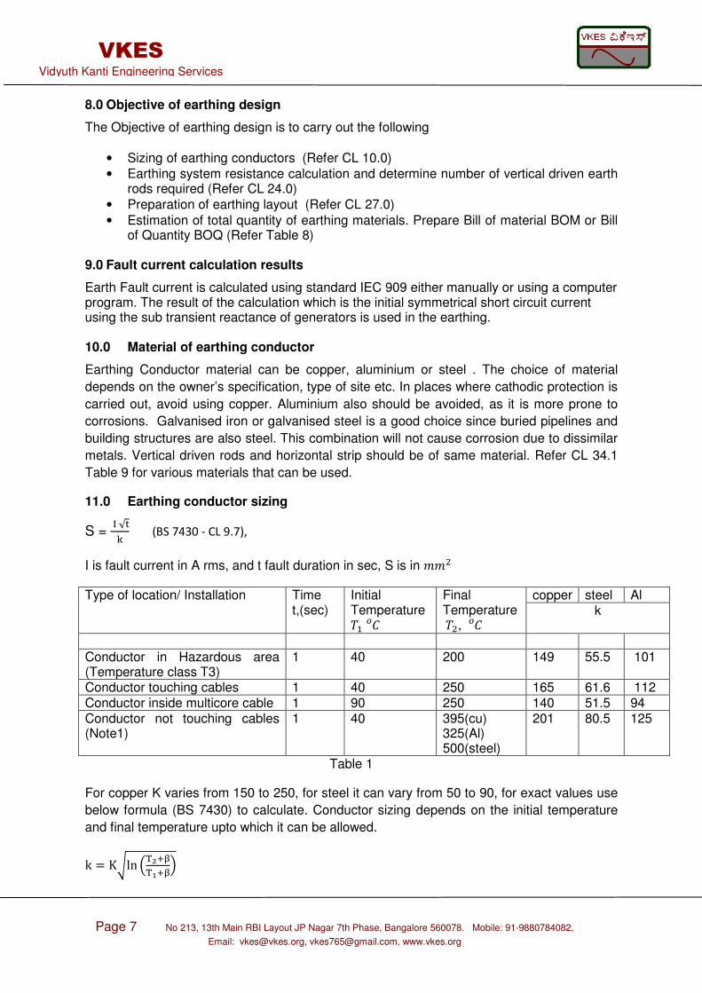
11.0 Earthing conductor sizing
S = √ (BS 7430 - CL 9.7),
I is fault current in A rms, and t fault duration in sec, S is in Type of location/ Installation Time
t,(sec) Initial Temperature
Final Temperature,
copper steel Al k
Conductor in Hazardous area (Temperature class T3)
1 40 200 149 55.5 101
Conductor touching cables 1 40 250 165 61.6 112 Conductor inside multicore cable 1 90 250 140 51.5 94 Conductor not touching cables (Note1)
1 40 395(cu) 325(Al) 500(steel)
201 80.5 125
Table 1
For copper K varies from 150 to 250, for steel it can vary from 50 to 90, for exact values use
below formula (BS 7430) to calculate. Conductor sizing depends on the initial temperature
and final temperature upto which it can be allowed.
k = Kln
Page 8 No 213, 13th Main RBI Layout JP Nagar 7th Phase, Bangalore 560078. Mobile: 91-9880784082,
Email: [email protected], [email protected], www.vkes.org
VKES Vidyuth Kanti Engineering Services
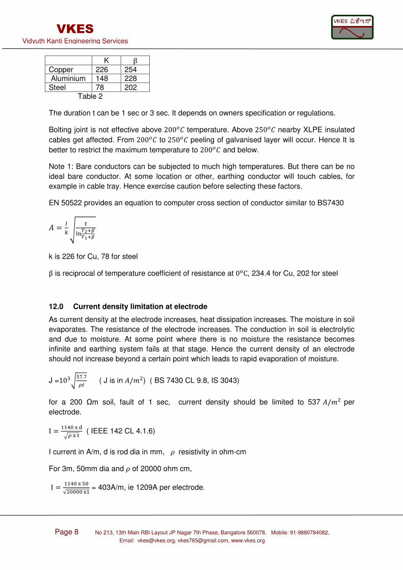
K β Copper 226 254 Aluminium 148 228 Steel 78 202 Table 2
The duration t can be 1 sec or 3 sec. It depends on owners specification or regulations.
Bolting joint is not effective above 200 temperature. Above 250 nearby XLPE insulated
cables get affected. From 200 to 250 peeling of galvanised layer will occur. Hence It is
better to restrict the maximum temperature to 200 and below.
Note 1: Bare conductors can be subjected to much high temperatures. But there can be no
ideal bare conductor. At some location or other, earthing conductor will touch cables, for
example in cable tray. Hence exercise caution before selecting these factors.
EN 50522 provides an equation to computer cross section of conductor similar to BS7430
= !"#$%&$%&
k is 226 for Cu, 78 for steel
β is reciprocal of temperature coefficient of resistance at 0'C, 234.4 for Cu, 202 for steel
12.0 Current density limitation at electrode
As current density at the electrode increases, heat dissipation increases. The moisture in soil
evaporates. The resistance of the electrode increases. The conduction in soil is electrolytic
and due to moisture. At some point where there is no moisture the resistance becomes
infinite and earthing system fails at that stage. Hence the current density of an electrode
should not increase beyond a certain point which leads to rapid evaporation of moisture.
J =10*+,.,.! ( J is in /) ( BS 7430 CL 9.8, IS 3043)
for a 200 Ωm soil, fault of 1 sec, current density should be limited to 537 / per
electrode.
I = 12345.3 ( IEEE 142 CL 4.1.6)
I current in A/m, d is rod dia in mm, 6 resistivity in ohm-cm
For 3m, 50mm dia and 6 of 20000 ohm cm,
I = 123+2√22223 = 403A/m, ie 1209A per electrode.
Page 9 No 213, 13th Main RBI Layout JP Nagar 7th Phase, Bangalore 560078. Mobile: 91-9880784082,
Email: [email protected], [email protected], www.vkes.org
VKES Vidyuth Kanti Engineering Services
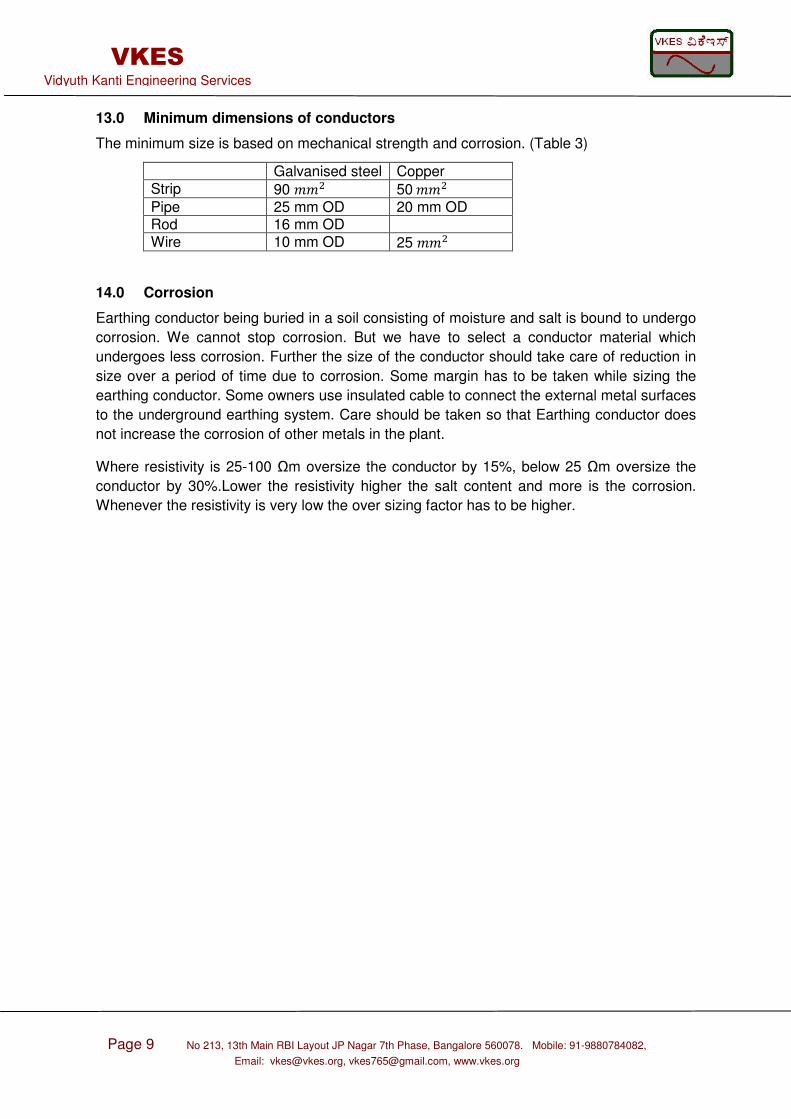
13.0 Minimum dimensions of conductors
The minimum size is based on mechanical strength and corrosion. (Table 3)
Galvanised steel Copper Strip 90 50 Pipe 25 mm OD 20 mm OD Rod 16 mm OD Wire 10 mm OD 25
14.0 Corrosion
Earthing conductor being buried in a soil consisting of moisture and salt is bound to undergo
corrosion. We cannot stop corrosion. But we have to select a conductor material which
undergoes less corrosion. Further the size of the conductor should take care of reduction in
size over a period of time due to corrosion. Some margin has to be taken while sizing the
earthing conductor. Some owners use insulated cable to connect the external metal surfaces
to the underground earthing system. Care should be taken so that Earthing conductor does
not increase the corrosion of other metals in the plant.
Where resistivity is 25-100 Ωm oversize the conductor by 15%, below 25 Ωm oversize the
conductor by 30%.Lower the resistivity higher the salt content and more is the corrosion.
Whenever the resistivity is very low the over sizing factor has to be higher.
Page 10 No 213, 13th Main RBI Layout JP Nagar 7th Phase, Bangalore 560078. Mobile: 91-9880784082,
Email: [email protected], [email protected], www.vkes.org
VKES Vidyuth Kanti Engineering Services
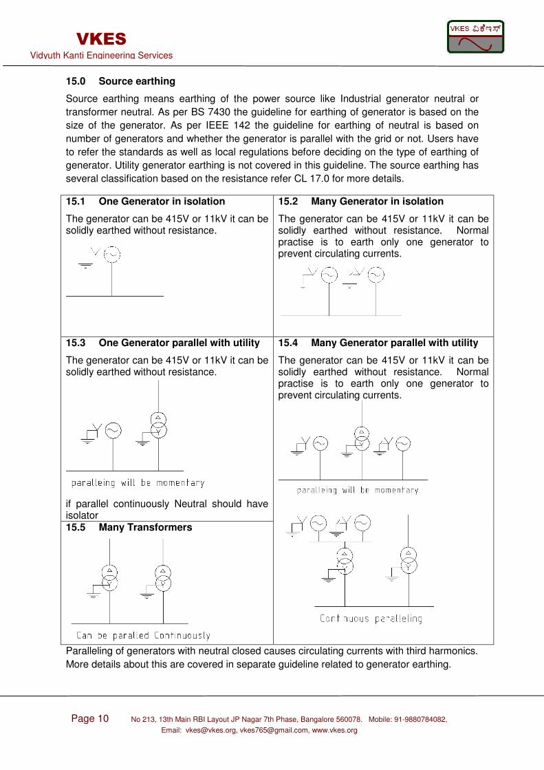
15.0 Source earthing
Source earthing means earthing of the power source like Industrial generator neutral or
transformer neutral. As per BS 7430 the guideline for earthing of generator is based on the
size of the generator. As per IEEE 142 the guideline for earthing of neutral is based on
number of generators and whether the generator is parallel with the grid or not. Users have
to refer the standards as well as local regulations before deciding on the type of earthing of
generator. Utility generator earthing is not covered in this guideline. The source earthing has
several classification based on the resistance refer CL 17.0 for more details.
15.1 One Generator in isolation
The generator can be 415V or 11kV it can be solidly earthed without resistance.
15.2 Many Generator in isolation
The generator can be 415V or 11kV it can be solidly earthed without resistance. Normal practise is to earth only one generator to prevent circulating currents.
15.3 One Generator parallel with utility
The generator can be 415V or 11kV it can be solidly earthed without resistance.
if parallel continuously Neutral should have isolator
15.4 Many Generator parallel with utility
The generator can be 415V or 11kV it can be solidly earthed without resistance. Normal practise is to earth only one generator to prevent circulating currents.
15.5 Many Transformers
Paralleling of generators with neutral closed causes circulating currents with third harmonics.
More details about this are covered in separate guideline related to generator earthing.
Page 11 No 213, 13th Main RBI Layout JP Nagar 7th Phase, Bangalore 560078. Mobile: 91-9880784082,
Email: [email protected], [email protected], www.vkes.org
VKES Vidyuth Kanti Engineering Services
15.6 Transformer neutral earthing
Neutral at the Secondary of the Transformer with star winding are earthed either with a
resistance or solidly earthed depending on the type of earthing system as given in CL 17.0
15.7 Earthing of UPS neutral
If neutral in the star winding of the UPS output transformer is not earthed, then it will be
difficult to detect a single line to ground fault, it will lead to over voltages. Hence it is
recommended to earth the neutral of UPS also. UPS vendor and Control system equipment
vendor should be consulted at the initial stage of engineering to decide on the type of
earthing of UPS neutral.
16.0 Types of earthing based on resistance
The neutral can be earthed either by inserting a resistor or without a resistor between the
neutral and the earth electrode. The different types of earthing based on this connection are:
Solidly grounded system, Unearthed or ungrounded system, Resistance earthed system.
16.1 Solidly grounded system
There is no intentional resistor introduced between the neutral/ star point of the
transformer/generator and the earth electrode. The single line to ground fault current will be
high in this system. Hence detecting the fault is not difficult. There will be no transient
overvoltage. Hence higher insulation need not be used. Most of the Transmission and
distribution system are solidly grounded.
16.2 Unearthed or ungrounded system
There is no connection between the neutral/star point of the transformer/generator and the
earth electrode. The single line to ground fault current will be very low. Hence detecting the
fault is very difficult. There will be high transient overvoltage. Hence higher insulation needs
to be used. This system is very rarely used except in some system like hospitals.
16.3 Reactance earthed system and resonant earthed system
This is not covered in this guideline as this earthing system is used less frequently. Readers
can refer the standards for more details.
16.4 Resistance earthed system
A resistor is introduced between the neutral/star point of the transformer/generator and the
earth electrode. The resistor is called NGR – neutral grounding resistor. If used along with a
transformer it is called NGT Neutral grounding transformer. When the voltage is high a NGT
along with NGR is used. The single line to ground fault current will be limited in this system.
Hence detecting fault need sensitive relays. However there will be no transient overvoltage.
Hence higher insulation need not be used. The advantage of limiting the fault current is that
there will be no welding of stampings of motors during a fault. Hence this system is very
common in industries having 3.3kV, 6.6kV or 11kV motors. The advantage is that the system
can continue to operate even if there is a fault. But fault need to be isolated or else a second
ground fault will lead to line to line fault.
Page 12 No 213, 13th Main RBI Layout JP Nagar 7th Phase, Bangalore 560078. Mobile: 91-9880784082,
Email: [email protected], [email protected], www.vkes.org
VKES Vidyuth Kanti Engineering Services
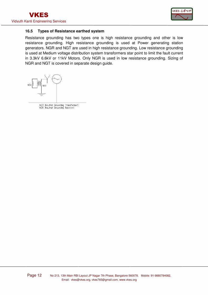
16.5 Types of Resistance earthed system
Resistance grounding has two types one is high resistance grounding and other is low
resistance grounding. High resistance grounding is used at Power generating station
generators. NGR and NGT are used in high resistance grounding. Low resistance grounding
is used at Medium voltage distribution system transformers star point to limit the fault current
in 3.3kV 6.6kV or 11kV Motors. Only NGR is used in low resistance grounding. Sizing of
NGR and NGT is covered in separate design guide.

Page 13 No 213, 13th Main RBI Layout JP Nagar 7th Phase, Bangalore 560078. Mobile: 91-9880784082,
Email: [email protected], [email protected], www.vkes.org
VKES Vidyuth Kanti Engineering Services
17.0 Different types of LV earthing system (BS 7430)
Before beginning the LV system earthing, first check type of system to be used. Is it TN-S,
TN-C, TN-CS, TT, IT. Selection of the type depends on local regulations.
Source Load T T
T N C/S
T I X N T X
N N X N I X
I T
I N X
I I X
Table 4
TN system has three variations.
TNC- Protective earth (PE) and Neutral are combined
TNS- Protective earth (PE) and Neutral are Separating
TNCS- combination of TNC upto some point from the
source and TNS after some point upto the load
TT system
There is no Protective earth (PE) conductor from
source to load
Earthing at source and load are independent. Fault
current flow through the earth
IT system
There is no Protective earth (PE) conductor from
source to load. The source is unearthed
Load side is provided with an independent earthing.
Fault current flow through the earth and returns to the
neutral via coupling capacitor.
Source side earthing type can be T or I
T : effectively earthed , I : un earthed.
Load side earthing can be T or N
T : load side has own earthing terminal or earth electrode,
N: Load side earthing system connected to source side earthing
Page 14 No 213, 13th Main RBI Layout JP Nagar 7th Phase, Bangalore 560078. Mobile: 91-9880784082,
Email: [email protected], [email protected], www.vkes.org
VKES Vidyuth Kanti Engineering Services
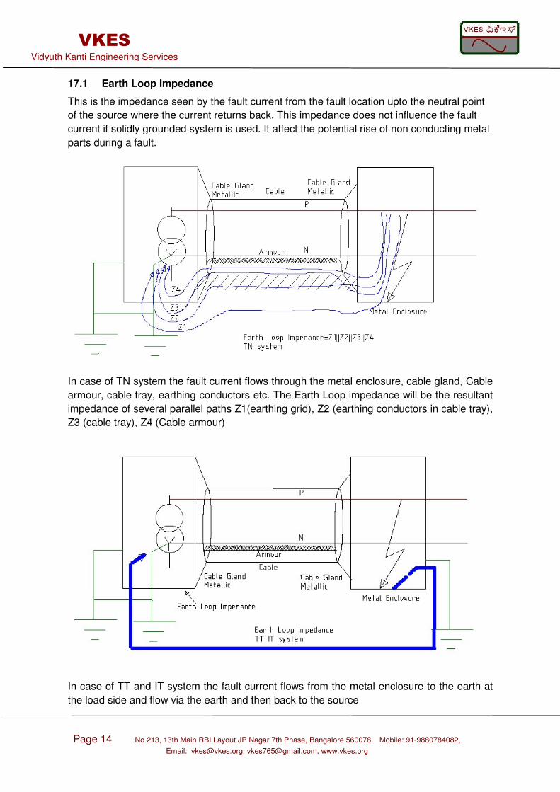
17.1 Earth Loop Impedance
This is the impedance seen by the fault current from the fault location upto the neutral point
of the source where the current returns back. This impedance does not influence the fault
current if solidly grounded system is used. It affect the potential rise of non conducting metal
parts during a fault.
In case of TN system the fault current flows through the metal enclosure, cable gland, Cable
armour, cable tray, earthing conductors etc. The Earth Loop impedance will be the resultant
impedance of several parallel paths Z1(earthing grid), Z2 (earthing conductors in cable tray),
Z3 (cable tray), Z4 (Cable armour)
In case of TT and IT system the fault current flows from the metal enclosure to the earth at
the load side and flow via the earth and then back to the source
Page 15 No 213, 13th Main RBI Layout JP Nagar 7th Phase, Bangalore 560078. Mobile: 91-9880784082,
Email: [email protected], [email protected], www.vkes.org
VKES Vidyuth Kanti Engineering Services
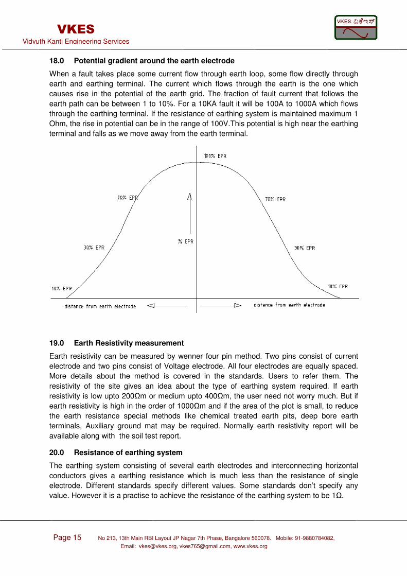
18.0 Potential gradient around the earth electrode
When a fault takes place some current flow through earth loop, some flow directly through
earth and earthing terminal. The current which flows through the earth is the one which
causes rise in the potential of the earth grid. The fraction of fault current that follows the
earth path can be between 1 to 10%. For a 10KA fault it will be 100A to 1000A which flows
through the earthing terminal. If the resistance of earthing system is maintained maximum 1
Ohm, the rise in potential can be in the range of 100V.This potential is high near the earthing
terminal and falls as we move away from the earth terminal.
19.0 Earth Resistivity measurement
Earth resistivity can be measured by wenner four pin method. Two pins consist of current
electrode and two pins consist of Voltage electrode. All four electrodes are equally spaced.
More details about the method is covered in the standards. Users to refer them. The
resistivity of the site gives an idea about the type of earthing system required. If earth
resistivity is low upto 200Ωm or medium upto 400Ωm, the user need not worry much. But if
earth resistivity is high in the order of 1000Ωm and if the area of the plot is small, to reduce
the earth resistance special methods like chemical treated earth pits, deep bore earth
terminals, Auxiliary ground mat may be required. Normally earth resistivity report will be
available along with the soil test report.
20.0 Resistance of earthing system
The earthing system consisting of several earth electrodes and interconnecting horizontal
conductors gives a earthing resistance which is much less than the resistance of single
electrode. Different standards specify different values. Some standards don’t specify any
value. However it is a practise to achieve the resistance of the earthing system to be 1Ω.

Page 16 No 213, 13th Main RBI Layout JP Nagar 7th Phase, Bangalore 560078. Mobile: 91-9880784082,
Email: [email protected], [email protected], www.vkes.org
VKES Vidyuth Kanti Engineering Services
21.0 Measurement of electrode resistance
Earth resistance can be measured by different methods like fall of potential methods. The
methods will be covered in a different guideline along with some practical site measurement
examples.
22.0 What all needs to be earthed
All Non conducting Metal parts in a plant needs to be earthed. All the enclosures of various
electrical equipment need to be earthed. Refer the Single line diagram of the plant, this gives
an idea about all the electrical equipments used in the plant. All the equipments which needs
to be earthed has to be shown in the earthing layout as shown in CL 23.0, CL 27.0, CL 34.0.
Refer the table 7 for typical size of earthing conductor and what all needs to be earthed.
22.1 Source Neutral earthing
All Neutral of Generators, UPS, Transformers needs to be earthed. (Refer CL 15 for more
details). Enclosures of UPS, Transformer and Generator are earthed separately but
interconnected below earth.
22.2 Cable Armour earthing
The Main purpose of cable armour is to provide mechanical protection for the cable from
external damages and also provide a tensile strength. Cable armour has a big advantage; it
carries the fault current in case of fault in a cable or in case of fault at cable terminal. Fault
develops inside a cable due to aging and this is due to one factor called water treeing. A tree
like path is formed from the conductors of the cable to the outer surface of the cable. This
path consists of tiny water particles which conduct electricity. If cable armour with earthing is
provided, the water tree leads to a single line to ground fault which can be detected. If cable
armour is not provided or earthing is not provided, it may lead to a Single line to ground fault
which cannot be detected and subsequently it leads to line to line fault.The cable armour has
to be earthed either at both the ends or at one end. If cable armour is earthed at both ends it
may lead to circulating currents. In that case where there are high circulating currents, the
cable needs to be derated. Capability of Cable armour to carry the fault current for certain
duration should be verified. Armour of Single core cable should not be earthed at both the
ends as it leads to high circulating currents. If unarmoured cable is used then a separate
core with protective earth is required.
22.3 Cable Tray earthing
Cable tray are made of sections of some typical length like 3 meter. Each section tray is
joined to the next section through metallic plates or through welding . Hence the entire cable
tray is electrically continuous. Where the tray is discontinuous it needs to be connected to
the next section through a cable. Some users have practise of running bare conductor or
insulated conductor along the cable tray.
22.4 Electrical Panel and Distribution boards earthing
All Electrical panels and Distribution boards located indoor or outdoor needs to be earthed.
The panels may be 415V or 3.3kV or 6.6kV or 11kV or 33kV . Panels are provided with a
continuous earthing conductor inside the panel by the manufacturer. This conductor needs
to be connected to the earthing system inside the electrical room. All electrical equipments
Page 17 No 213, 13th Main RBI Layout JP Nagar 7th Phase, Bangalore 560078. Mobile: 91-9880784082,
Email: [email protected], [email protected], www.vkes.org
VKES Vidyuth Kanti Engineering Services
inside switchgear room can be connected at one common place which can be connected to
main earth grid located outdoor.
22.5 Junction Box earthing
Enclosure of Small JB used for lighting needs to be earthed if it is metallic. If JB are non
metallic they should be earthed if provided with a metal plate inside. If Armoured control
cables terminate at the metallic JB enclosure, then a metallic gland has to be used which will
provide electrical continuity for the earthing.
22.6 Motor and Push button station earthing
Motor body has to be earthed directly to earth grid. Motor push button station (PBS) shall
also be earthed. If the PBS enclosure is mounted on Metal frame, then the frame itself can
be earthed near its footing or the PBS can be earthed directly.
22.7 Lighting poles and fixtures earthing
All Lighting fixtures shall receive three wires: phase, neutral and earth conductors from the
junction box. Fixture earthing is carried out with the earth wire. The JB is earthed by one or
all of the following: cable armour, earth wire connected directly to earth grid, earth wire
connected to pole, if metallic JB is mounted on metallic poles it will be earthed by default.
The Lighting pole shall be earthed directly to the earth grid.
22.8 Tanks, Vessels, Piping earthing
Non electrical metallic equipments like tanks, vessels, pipes etc which are process related
also needs to be earthed to protect them from lightning strike and static charges. The
metallic equipments shall be provided with earth terminal.
22.9 Package equipments earthing
All package equipments like Instrument air compressors, Chemical injection skids, Crane,
Hoists etc should be earthed at two locations on the skid designated by the vendor. Earthing
of various panels, motors, lighting etc within the package equipment internally shall be taken
care by the manufacturer.
22.10 Lightning Protection system earthing
Lightning Protection system will have its own earth pits, horizontal conductors and vertical
down conductors. LP earthing system needs to be interconnected with the main earth grid
below ground. Detailed design about LP earthing system is given in a separate guide.
22.11 Electronic equipments earthing system
Electronic equipments are normally provided with separate earthing system. But same
needs to be connected to the Power system earthing below earth. If this is not done, then
there can be back flash into electronic earth during lightning and this can damage the
insulation of the electronic equipment. Electronic earthing system can be completely isolated
from other earthing system if its insulation can withstand voltage surge due to lightning. But
this is not economical and practicable. Hence connecting both the system is required.
Page 18 No 213, 13th Main RBI Layout JP Nagar 7th Phase, Bangalore 560078. Mobile: 91-9880784082,
Email: [email protected], [email protected], www.vkes.org
VKES Vidyuth Kanti Engineering Services
22.12 Earthing of utility pipes
Water pipes or any utility pipes entering substation may be earthed or left unearthed
depending on the local regulations. If it is earthed inside the substation, then the joint at the
boundary of substation needs to be insulated to prevent transfer of potential from substation
to outside. In Industrial site or building Water pipes shall not be used for earthing but it shall
be bonded to the earthing system. Refer the local and national regulations before following
standards and guidelines related to this clause.
22.13 Earthing of steel reinforced bars of structures and buildings
It is advantageous to earth the steel reinforced bars (rebars) embedded inside a concrete.
The concrete has low earth resistivity and along with absorbed moisture and rebars, it acts
as a low resistance earth electrode. When several such columns are interconnected to the
earthing system they provide a good low resistance for the overall earthing system.
Connecting rebars with earthing system also reduces the electrical noise interferences and
EMC problems. During lightning strike there will be no back flash from earthing grid to
concrete rebars if they are interconnected. However there are some disadvantages, the
rebars will undergo corrosion due to some residual DC currents in the earthing system and
during fault the current in rebars will cause heating, which will reduce the moisture in
concrete. This can create cracks in the structure. Hence as per some regulations the rebars
should not be connected to the earthing system. Hence refer to the local and national
regulations before following any standards and guidelines related to this clause.
Page 19 No 213, 13th Main RBI Layout JP Nagar 7th Phase, Bangalore 560078. Mobile: 91-9880784082, Email: [email protected], [email protected], www.vkes.org
VKES Vidyuth Kanti Engineering Services
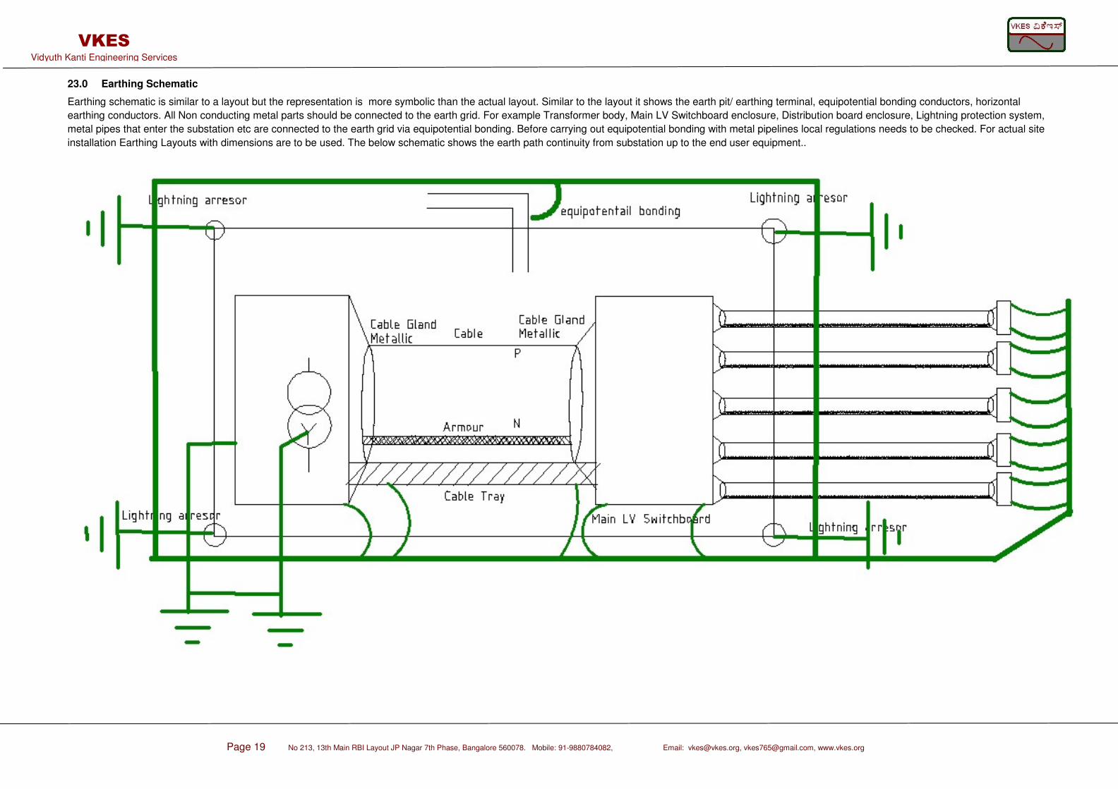
23.0 Earthing Schematic
Earthing schematic is similar to a layout but the representation is more symbolic than the actual layout. Similar to the layout it shows the earth pit/ earthing terminal, equipotential bonding conductors, horizontal
earthing conductors. All Non conducting metal parts should be connected to the earth grid. For example Transformer body, Main LV Switchboard enclosure, Distribution board enclosure, Lightning protection system,
metal pipes that enter the substation etc are connected to the earth grid via equipotential bonding. Before carrying out equipotential bonding with metal pipelines local regulations needs to be checked. For actual site
installation Earthing Layouts with dimensions are to be used. The below schematic shows the earth path continuity from substation up to the end user equipment..
Page 20 No 213, 13th Main RBI Layout JP Nagar 7th Phase, Bangalore 560078., Mobile: 91-9880784082, Email:
[email protected], [email protected], www.vkes.org
VKES Vidyuth Kanti Engineering Services
24.0 Types of Electrodes and their resistances
Different types of electrodes are: Plate, Pipe/Rod, Strip, Mesh. A given earthing system may
consist of all of these or few of them. Normally strip electrode (Horizontal) and Rod electrode
(vertical) will be used more often.
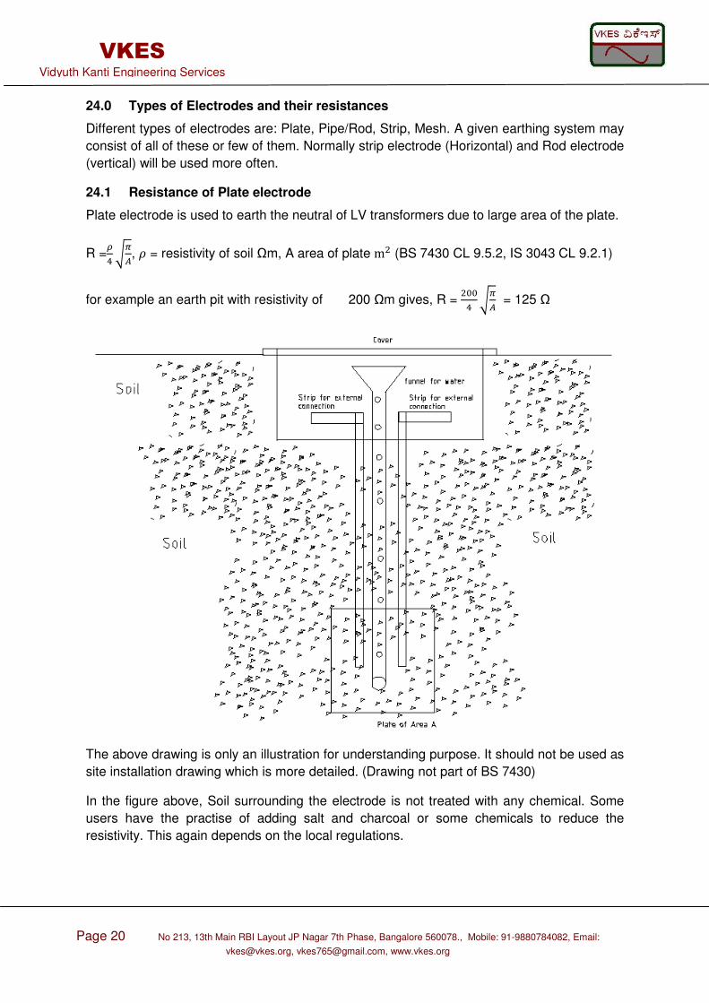
24.1 Resistance of Plate electrode
Plate electrode is used to earth the neutral of LV transformers due to large area of the plate.
R =.178, 6 = resistivity of soil Ωm, A area of plate m (BS 7430 CL 9.5.2, IS 3043 CL 9.2.1)
for example an earth pit with resistivity of 200 Ωm gives, R = 221 78 = 125 Ω
The above drawing is only an illustration for understanding purpose. It should not be used as
site installation drawing which is more detailed. (Drawing not part of BS 7430)
In the figure above, Soil surrounding the electrode is not treated with any chemical. Some
users have the practise of adding salt and charcoal or some chemicals to reduce the
resistivity. This again depends on the local regulations.
Page 21 No 213, 13th Main RBI Layout JP Nagar 7th Phase, Bangalore 560078., Mobile: 91-9880784082, Email:
[email protected], [email protected], www.vkes.org
VKES Vidyuth Kanti Engineering Services
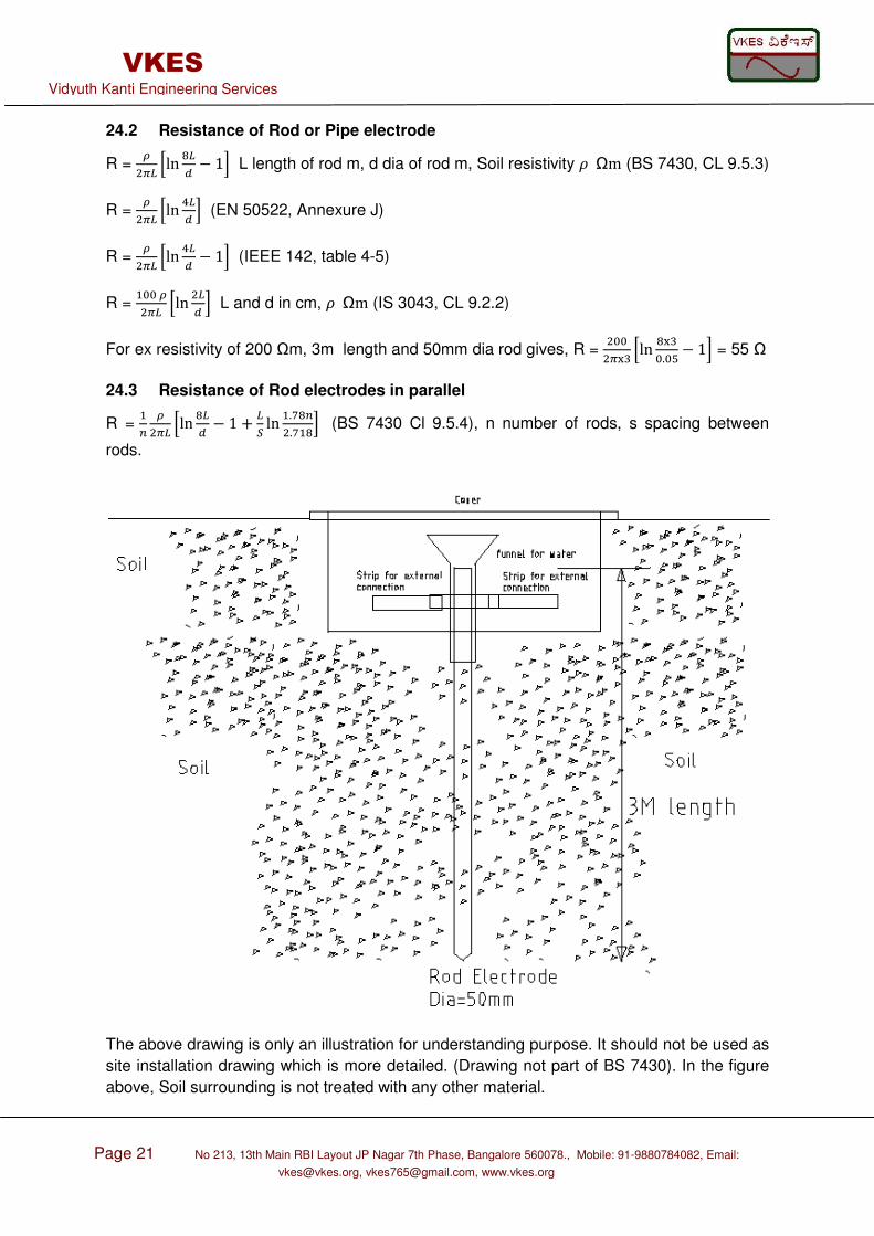
24.2 Resistance of Rod or Pipe electrode
R = .7: ;ln <:= − 1? L length of rod m, d dia of rod m, Soil resistivity 6Ωm (BS 7430, CL 9.5.3)
R = .7: ;ln 1:= ? (EN 50522, Annexure J)
R = .7: ;ln 1:= − 1? (IEEE 142, table 4-5)
R = 22.7: ;ln := ? L and d in cm, 6Ωm (IS 3043, CL 9.2.2)
For ex resistivity of 200 Ωm, 3m length and 50mm dia rod gives, R = 2273* ;ln <3*2.2+− 1? = 55 Ω
24.3 Resistance of Rod electrodes in parallel
R = @ .7: ;ln <:= − 1 + :B ln .,<@.,<? (BS 7430 Cl 9.5.4), n number of rods, s spacing between
rods.
The above drawing is only an illustration for understanding purpose. It should not be used as
site installation drawing which is more detailed. (Drawing not part of BS 7430). In the figure
above, Soil surrounding is not treated with any other material.
Page 22 No 213, 13th Main RBI Layout JP Nagar 7th Phase, Bangalore 560078., Mobile: 91-9880784082, Email:
[email protected], [email protected], www.vkes.org
VKES Vidyuth Kanti Engineering Services
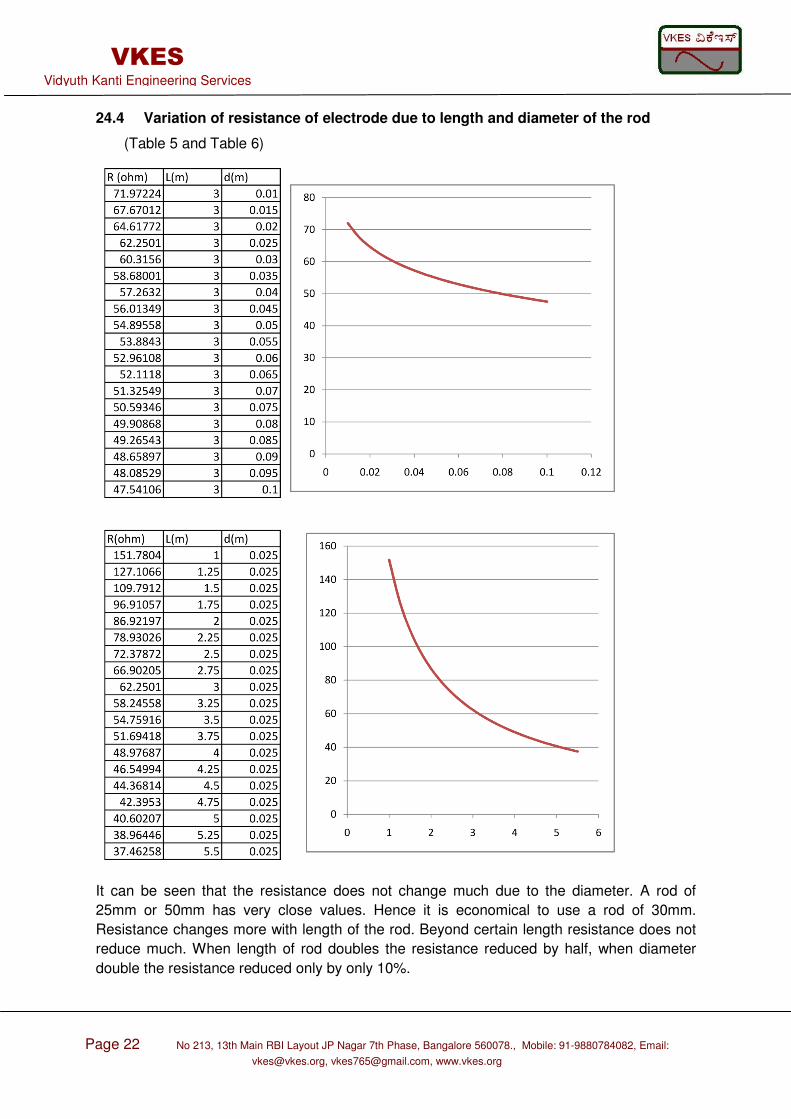
24.4 Variation of resistance of electrode due to length and diameter of the rod
(Table 5 and Table 6)
It can be seen that the resistance does not change much due to the diameter. A rod of
25mm or 50mm has very close values. Hence it is economical to use a rod of 30mm.
Resistance changes more with length of the rod. Beyond certain length resistance does not
reduce much. When length of rod doubles the resistance reduced by half, when diameter
double the resistance reduced only by only 10%.
Page 23 No 213, 13th Main RBI Layout JP Nagar 7th Phase, Bangalore 560078., Mobile: 91-9880784082, Email:
[email protected], [email protected], www.vkes.org
VKES Vidyuth Kanti Engineering Services
24.5 Resistance of straight Strip
R = .7: ;ln :.<+C=? , h is depth of electrode in m, L is length of strip, d is the diameter of round
conductor or diameter of equivalent cross section area of the strip (BS 7430 CL 9.5.5)
R = .7: ;ln := ? , d= half width of earth strip (EN 50522, Annexure J-2)
R = 22.7: ;ln 1:! ? , t= width of earth strip in cm (IS 3043 CL 9.2.3)
24.6 Resistance of Mesh
R=0.443 .√8 + .: , A area of mesh m, L total length of conductor m (BS 7430 CL9.5.6)
R=.D D is diameter of circle with same area as the mesh (EN 50522 Annexure J2)
24.7 Resistivity of electrodes encased in Low resistivity materials
R = .7: ;ln 1:= − 1? - .7: ;ln 1:= − 1? +
.7: ;ln 1:= − 1? (IEEE Tran Industry and Gen appln Vol IGA-6,No 4, July/Aug 1970, Page 8)
E dia of rod m, E dia of encased soil, Soil resistivity 6Ωm, encased Soil resistivity 6Ωm
24.8 Earthing of steel reinforced concrete foundations
FG= 7: ;H6I − 6J ln 1 + KL + 6 ln :L ? (BS 7430 CL 9.5.8.5)
6I is resistivity of concrete in Ωm, M is thickness of concrete between rods and soild in m, Z
is geometric mean distance of rod clusters.
25.0 Treated earth electrodes
The resistance of earth electrode depends on the earth surrounding it. Earth is very large.
Practically only few meters of earth around the electrode influences the resistance. As per
IEEE 142 area close to 1 feet around the electrode influences 68% of the earth resistance.
By adding Charcoal with salt, or Bentonite or mixing soil with salts like sodium chloride,
calcium chloride, magnesium sulphate, copper sulphate or some other chemicals or by
addition of some chemicals etc resistance can be reduced. Adding 5% salt in moisture will
be very effective in reducing the resistance. Addition of materials around the soil leads to soil
contamination and corrosion of electrode. Hence local regulations should be checked if
addition of chemicals around the soil is allowed. These types of electrodes require regular
monitoring and addition of moisture content. But at locations with very high resistivity it is
very useful method to obtain low resistance earth electrodes.
Page 24 No 213, 13th Main RBI Layout JP Nagar 7th Phase, Bangalore 560078., Mobile: 91-9880784082, Email:
[email protected], [email protected], www.vkes.org
VKES Vidyuth Kanti Engineering Services
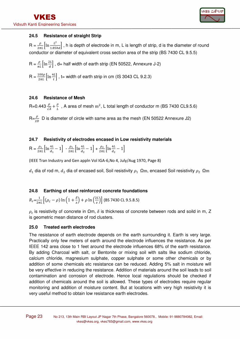
26.0 Auxiliary earth grid
A Separate earth mat/grid covering large area is designed and installed at some other
remote location, this is connected to the plant or building earthing system which does not
have large area to produce a low resistance earthing system. This design requires separate
additional land which needs to be fenced to prevent access.
Page 25 No 213, 13th Main RBI Layout JP Nagar 7th Phase, Bangalore 560078., Mobile: 91-9880784082, Email: [email protected], [email protected], www.vkes.org
VKES Vidyuth Kanti Engineering Services
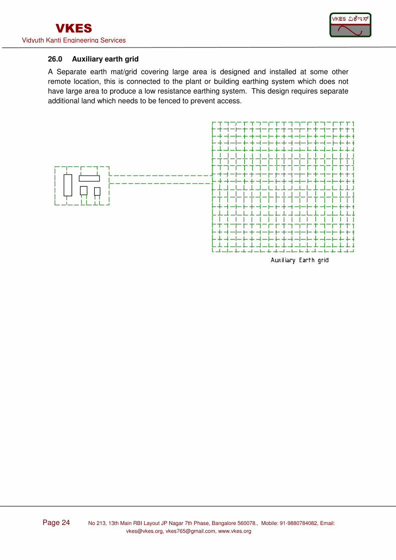
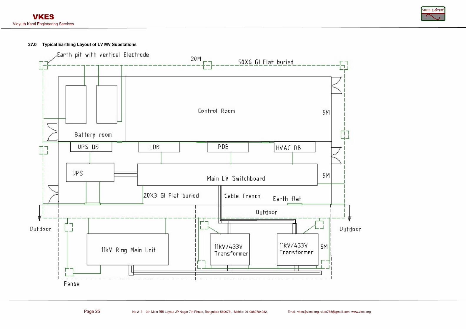
27.0 Typical Earthing Layout of LV MV Substations
Page 26 No 213, 13th Main RBI Layout JP Nagar 7th Phase, Bangalore 560078., Mobile: 91-9880784082,
Email: [email protected], [email protected], www.vkes.org
VKES Vidyuth Kanti Engineering Services
28.0 Layout Requirement
During the preparation of Earthing layout certain aspects like spacing between electrodes,
depth of horizontal conductor, distance between building wall and electrode etc needs to be
taken care. When horizontal electrodes are installed they should be surrounded by soil. They
should not be surrounded by stones and gravels.
28.1 Spacing between electrodes
When several electrodes are used to reduce the overall resistance, ensure that space
between each electrode is equal to depth of electrode or preferably twice the depth.
28.2 Distance between electrode and building wall
Maintain a clearance between electrode and building wall. This is required for proper
excavation, maintenance, and to prevent back flash if building is not bonded
28.3 Depth of horizontal conductor or connecting conductors
Horizontal conductors connecting all the vertical driven electrode shall be laid below 0.5M
from the ground level. The area surrounding this conductors should have soil. Lower depth
will damage the conductors during construction, larger depth will lead to higher cost. In cold
climates depth has to be high to escape the frozen soil.
29.0 Stray Currents
Currents are induced in earthing conductor due to a current flow in neighbouring conductors.
This current create problem for communication. screening and separation can mitigate this.
30.0 Common mode noise
When there are third harmonics or unbalance currents in a system, it leads to a continuous
current which will flow from the neutral to the earth. Due to this flow of current there is a
small voltage drop from neutral to earth. This voltage may be around 2V, it is called common
mode noise. This voltage may not cause safety hazard to people, but it creates interference
and malfunction in electronic equipments. To mitigate it, third harmonics and unbalance
problem has to be solved.
31.0 Typical Calculation of Earth electrode resistance of substation
Refer the typical substation layout shown above in CL 27.0. This consists of electrodes,
straight run and mesh. Together the total resistance is calculated as given below.
31.1 Resistance of Rod electrodes in parallel (BS 7430)
R = # ρπN ;ln <N4 − 1 + NO ln .,<#.,<? = 22π* ;ln <P*2.2+− 1 + *+ ln .,<P.,< ?= 5.8Ω
31.2 Resistance of straight Strip (BS 7430)
R = ρπN ;ln N.<+Q4? =
22π2 ;ln 2.<+P2.+P2.2+?=14.4Ω
31.3 Resistance of Mesh (BS 7430)
R=0.443 ρ√R+ ρN = 0.443 22√*22+ 22,2 = 7.96Ω
Total resistance of the earthing system = 1/(1/5.8+1/14.4+1/7.96)=2.72Ω
Page 27 No 213, 13th Main RBI Layout JP Nagar 7th Phase, Bangalore 560078., Mobile: 91-9880784082,
Email: [email protected], [email protected], www.vkes.org
VKES Vidyuth Kanti Engineering Services
32.0 Type of joints
Different types of joints that can be used to connect one earthing conductor to another
conductor are: Welding, exothermic, Brazing, Bolting etc. If may be preferred to do bolting at
a petrochemical site to avoid fire. Brazing, welding, exothermic are stronger and the contact
resistance will be much lower hence they should be used if there is no restriction in the site.
Brazing, welding, exothermic joints can tolerate high temperature than bolting joints.
33.0 Recommended dimensions of earthing Conductor (Table 7)
GS/GI mm Copper wire Tank 40X6 (flat), 70 to 185 Vessel -do- 70 to 185 Vent -do- 70 to 185 Flare -do- 70 to 185 Piperack/Pipe sleeper(every 30M) 20X5(flat) 25 Pipelines 20X5(flat) 25 to 70 Motor push button station Note, 6,8,10 16
Lighting Junction box Note 6, 10 16
Motor Note 3 Note 3 Light fixtures (integral with power cable) Note 6 4 to 10 Lighting poles 16 to 25 16 to 25
Transformer body Note 1 Note 1 Generator body Note 1 Note 1 Mechanical Package item 25, Note 1 25
UPS neutral Note 1 Note 1 Generator Neutral Note 1 Note 1 Transformer neutral Note 1 Note 1 Pump house steel column 25 to 70 25 to 70
Buildings 25X3 flat 25X3 flat Cable tray Note 1 Note 1 Cable trench Note 1 Note 1 Main earth Grid Note 1 Note 1 MV LV Switchgear Note 1 Note 1
Note 1: Depends on SC calculation and sizing Note 2: Above table is only for giving an idea, users to carry out calculation and refer the owner specification before choosing earthing conductor size Note 3: Many owners specification provide earthing conductor size based on motor kW rating. It is better to choose the earthing cable size based on the actual short circuit level at the motor terminal. Motor located close to the switchgear may require bigger size earthing cable than recommend by owner’s spec. Note 4: GS Galvanised steel, GI Galvanised iron Note 5: Cu or GI/GS can be used depending on owners choice. Note 6: It is better to earth the push button station, junction box with copper cable, instead of GI wire as it will be difficult to connect the GI wire.Note 7: insulated Cu wire is recommended for earthing of vessels, tanks and motors to avoid welding of. Lugs of the cable has to be tin coated Note 8: Motor Push button station (PBS) if mounted on metal frame, earthing from PBS can be connected to the metal frame itself. Normally the typical size mentioned in above table is furnished by the owner in their typical installation drawings. Same needs to be used. In case such drawings are not available, then this table can be referred. Note 9: Using Solid GI wire(without strands) will have termination problem
Page 28 No 213, 13th Main RBI Layout JP Nagar 7th Phase, Bangalore 560078., Mobile: 91-9880784082, Email: [email protected], [email protected], www.vkes.org
VKES Vidyuth Kanti Engineering Services
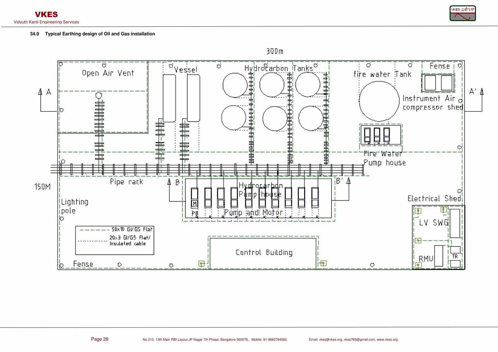
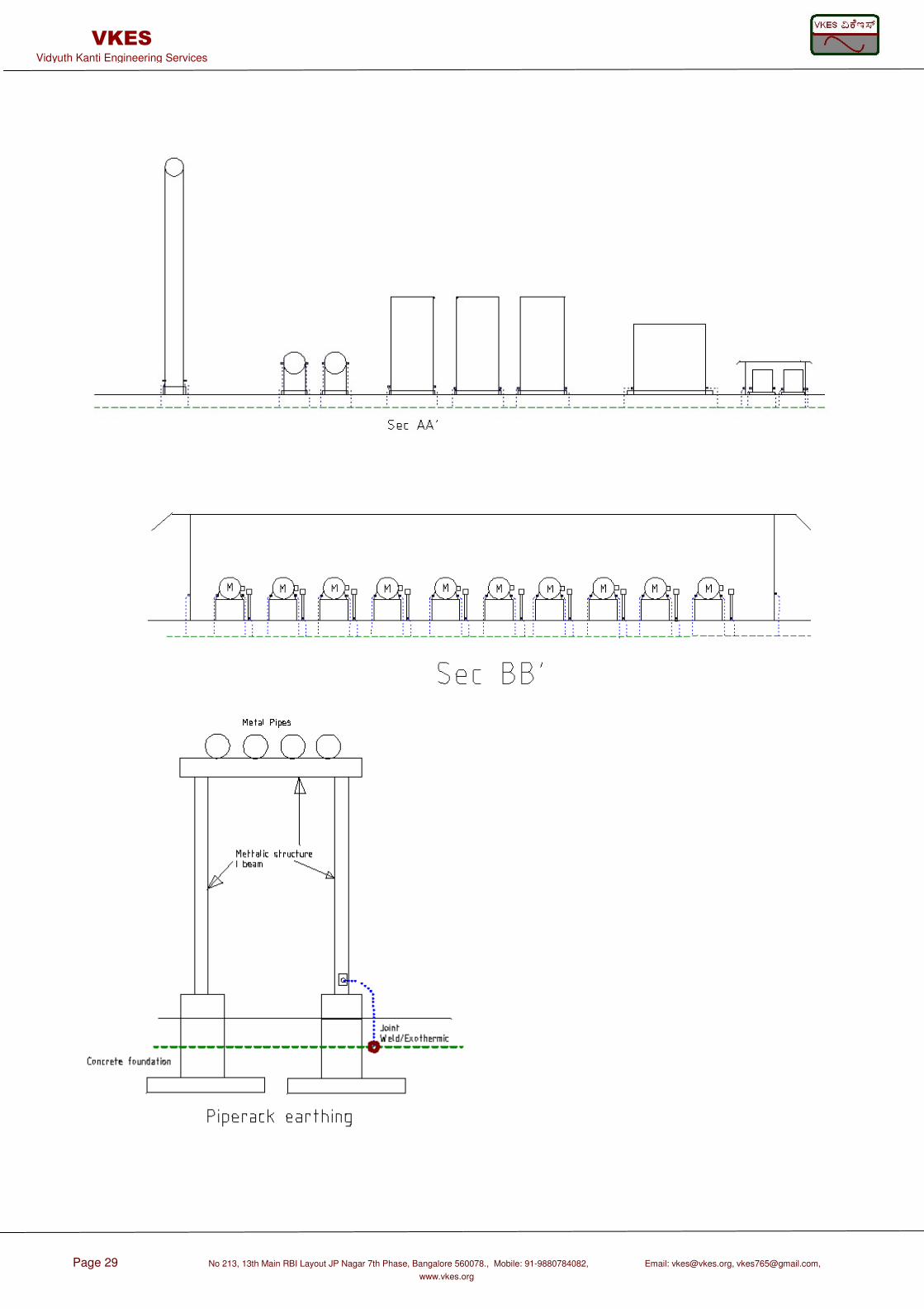
34.0 Typical Earthing design of Oil and Gas installation
Page 29 No 213, 13th Main RBI Layout JP Nagar 7th Phase, Bangalore 560078., Mobile: 91-9880784082, Email: [email protected], [email protected],
www.vkes.org
VKES Vidyuth Kanti Engineering Services
Page 30 No 213, 13th Main RBI Layout JP Nagar 7th Phase, Bangalore 560078., Mobile: 91-9880784082,
Email: [email protected], [email protected], www.vkes.org
VKES Vidyuth Kanti Engineering Services
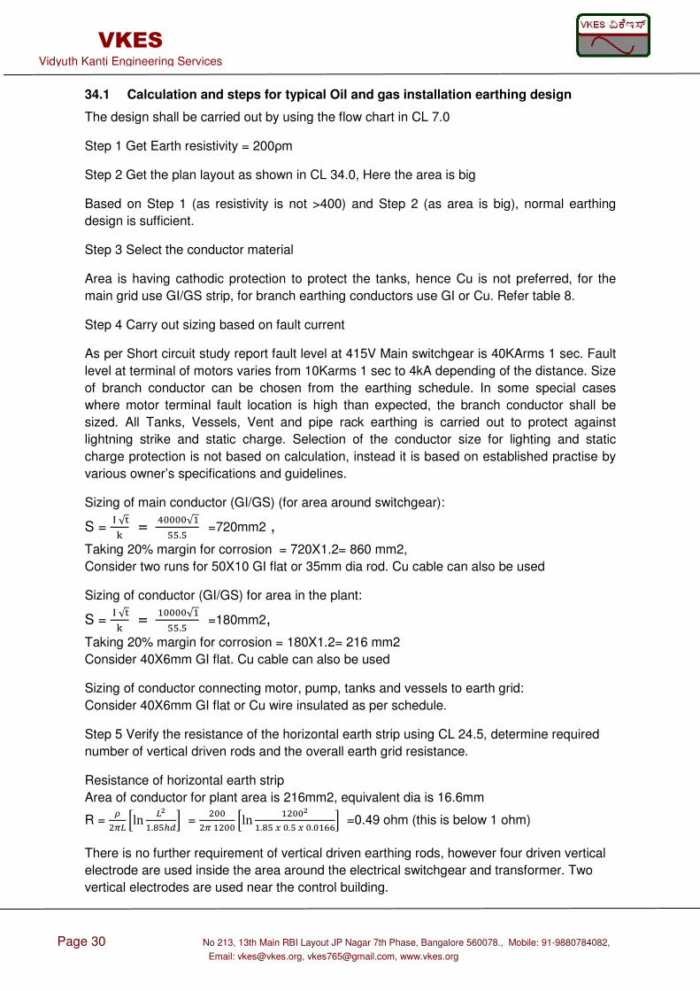
34.1 Calculation and steps for typical Oil and gas installation earthing design
The design shall be carried out by using the flow chart in CL 7.0
Step 1 Get Earth resistivity = 200ρm
Step 2 Get the plan layout as shown in CL 34.0, Here the area is big
Based on Step 1 (as resistivity is not >400) and Step 2 (as area is big), normal earthing
design is sufficient.
Step 3 Select the conductor material
Area is having cathodic protection to protect the tanks, hence Cu is not preferred, for the
main grid use GI/GS strip, for branch earthing conductors use GI or Cu. Refer table 8.
Step 4 Carry out sizing based on fault current
As per Short circuit study report fault level at 415V Main switchgear is 40KArms 1 sec. Fault
level at terminal of motors varies from 10Karms 1 sec to 4kA depending of the distance. Size
of branch conductor can be chosen from the earthing schedule. In some special cases
where motor terminal fault location is high than expected, the branch conductor shall be
sized. All Tanks, Vessels, Vent and pipe rack earthing is carried out to protect against
lightning strike and static charge. Selection of the conductor size for lighting and static
charge protection is not based on calculation, instead it is based on established practise by
various owner’s specifications and guidelines.
Sizing of main conductor (GI/GS) (for area around switchgear):
S = √ =
12222√++.+ =720mm2 ,
Taking 20% margin for corrosion = 720X1.2= 860 mm2,
Consider two runs for 50X10 GI flat or 35mm dia rod. Cu cable can also be used
Sizing of conductor (GI/GS) for area in the plant:
S = √ =
2222√++.+ =180mm2,
Taking 20% margin for corrosion = 180X1.2= 216 mm2
Consider 40X6mm GI flat. Cu cable can also be used
Sizing of conductor connecting motor, pump, tanks and vessels to earth grid:
Consider 40X6mm GI flat or Cu wire insulated as per schedule.
Step 5 Verify the resistance of the horizontal earth strip using CL 24.5, determine required
number of vertical driven rods and the overall earth grid resistance.
Resistance of horizontal earth strip
Area of conductor for plant area is 216mm2, equivalent dia is 16.6mm
R = .7: ;ln :.<+C=? =
22722 ;ln 22.<+S2.+S2.2TT? =0.49 ohm (this is below 1 ohm)
There is no further requirement of vertical driven earthing rods, however four driven vertical
electrode are used inside the area around the electrical switchgear and transformer. Two
vertical electrodes are used near the control building.
Page 31 No 213, 13th Main RBI Layout JP Nagar 7th Phase, Bangalore 560078., Mobile: 91-9880784082,
Email: [email protected], [email protected], www.vkes.org
VKES Vidyuth Kanti Engineering Services
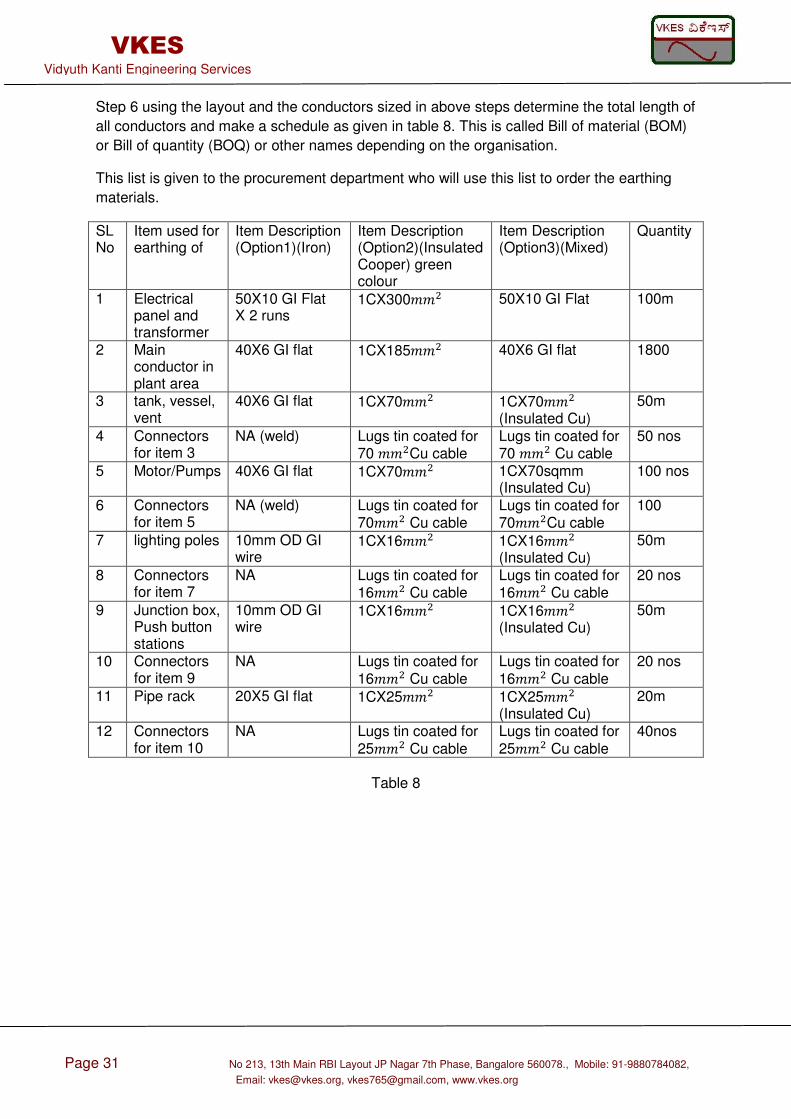
Step 6 using the layout and the conductors sized in above steps determine the total length of
all conductors and make a schedule as given in table 8. This is called Bill of material (BOM)
or Bill of quantity (BOQ) or other names depending on the organisation.
This list is given to the procurement department who will use this list to order the earthing
materials.
SL No
Item used for earthing of
Item Description (Option1)(Iron)
Item Description (Option2)(Insulated Cooper) green colour
Item Description (Option3)(Mixed)
Quantity
1 Electrical panel and transformer
50X10 GI Flat X 2 runs
1CX300 50X10 GI Flat 100m
2 Main conductor in plant area
40X6 GI flat 1CX185 40X6 GI flat 1800
3 tank, vessel, vent
40X6 GI flat 1CX70 1CX70 (Insulated Cu)
50m
4 Connectors for item 3
NA (weld) Lugs tin coated for 70 Cu cable
Lugs tin coated for 70 Cu cable
50 nos
5 Motor/Pumps 40X6 GI flat 1CX70 1CX70sqmm (Insulated Cu)
100 nos
6 Connectors for item 5
NA (weld) Lugs tin coated for 70 Cu cable
Lugs tin coated for 70Cu cable
100
7 lighting poles 10mm OD GI wire
1CX16 1CX16 (Insulated Cu)
50m
8 Connectors for item 7
NA Lugs tin coated for 16 Cu cable
Lugs tin coated for 16 Cu cable
20 nos
9 Junction box, Push button stations
10mm OD GI wire
1CX16 1CX16 (Insulated Cu)
50m
10 Connectors for item 9
NA Lugs tin coated for 16 Cu cable
Lugs tin coated for 16 Cu cable
20 nos
11 Pipe rack 20X5 GI flat 1CX25 1CX25 (Insulated Cu)
20m
12 Connectors for item 10
NA Lugs tin coated for 25 Cu cable
Lugs tin coated for 25 Cu cable
40nos
Table 8
Page 32 No 213, 13th Main RBI Layout JP Nagar 7th Phase, Bangalore 560078., Mobile: 91-9880784082,
Email: [email protected], [email protected], www.vkes.org
VKES Vidyuth Kanti Engineering Services
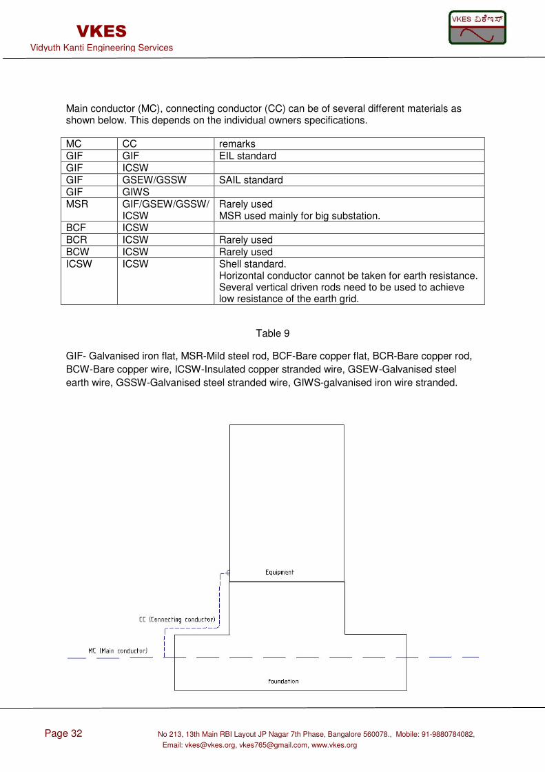
Main conductor (MC), connecting conductor (CC) can be of several different materials as shown below. This depends on the individual owners specifications. MC CC remarks GIF GIF EIL standard GIF ICSW GIF GSEW/GSSW SAIL standard GIF GIWS MSR GIF/GSEW/GSSW/
ICSW Rarely used MSR used mainly for big substation.
BCF ICSW BCR ICSW Rarely used BCW ICSW Rarely used ICSW ICSW Shell standard.
Horizontal conductor cannot be taken for earth resistance. Several vertical driven rods need to be used to achieve low resistance of the earth grid.
Table 9
GIF- Galvanised iron flat, MSR-Mild steel rod, BCF-Bare copper flat, BCR-Bare copper rod,
BCW-Bare copper wire, ICSW-Insulated copper stranded wire, GSEW-Galvanised steel
earth wire, GSSW-Galvanised steel stranded wire, GIWS-galvanised iron wire stranded.
Page 33 No 213, 13th Main RBI Layout JP Nagar 7th Phase, Bangalore 560078., Mobile: 91-9880784082, Email: [email protected], [email protected], www.vkes.org
VKES Vidyuth Kanti Engineering Services
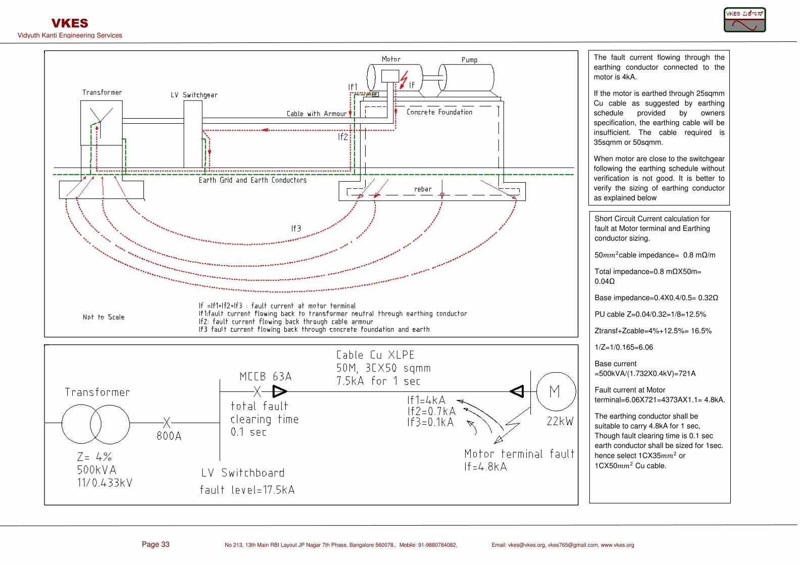
The fault current flowing through the
earthing conductor connected to the
motor is 4kA.
If the motor is earthed through 25sqmm
Cu cable as suggested by earthing
schedule provided by owners
specification, the earthing cable will be
insufficient. The cable required is
35sqmm or 50sqmm.
When motor are close to the switchgear
following the earthing schedule without
verification is not good. It is better to
verify the sizing of earthing conductor
as explained below
Short Circuit Current calculation for
fault at Motor terminal and Earthing
conductor sizing.
50cable impedance= 0.8 mΩ/m
Total impedance=0.8 mΩX50m=
0.04Ω
Base impedance=0.4X0.4/0.5= 0.32Ω
PU cable Z=0.04/0.32=1/8=12.5%
Ztransf+Zcable=4%+12.5%= 16.5%
1/Z=1/0.165=6.06
Base current
=500kVA/(1.732X0.4kV)=721A
Fault current at Motor
terminal=6.06X721=4373AX1.1= 4.8kA.
The earthing conductor shall be
suitable to carry 4.8kA for 1 sec,
Though fault clearing time is 0.1 sec
earth conductor shall be sized for 1sec.
hence select 1CX35 or
1CX50 Cu cable.
Page 34 No 213, 13th Main RBI Layout JP Nagar 7th Phase, Bangalore 560078., Mobile: 91-9880784082,
Email: [email protected], [email protected], www.vkes.org
VKES Vidyuth Kanti Engineering Services
35.0 Reference
• BS 7430: Code of practise of earthing
• IEEE 142: IEEE recommended practise of grounding of industrial and commercial power systems
• EN 50522: Earthing of power installations exceeding 1 kV a.c
• IS 3043: Code of practise for earthing
• IEEE Transaction Industry and General application Vol IGA-6,No 4, July/Aug 1970
Page 35 No 213, 13th Main RBI Layout JP Nagar 7th Phase, Bangalore 560078., Mobile: 91-9880784082,
Email: [email protected], [email protected], www.vkes.org
VKES Vidyuth Kanti Engineering Services
ABOUT VKES
Vidyuth Kanti Engineering Services is a Bangalore based Startup by Paneendra Kumar BL. Paneendra Kumar BL is a Charted Engineer (UK), Senior member IEEE (USA) , Associate member institute of engineers India. He has done Masters in power system from IIT Delhi and BE Electrical from RV college of engineering Bangalore. He has 15 years experience in Electrical Engineering of Transmission and Distribution, Industrial power distribution, Power plants, Oil and gas installations and Power quality. He has published papers in International journals. He is also part of few standards development.
Page 36 No 213, 13th Main RBI Layout JP Nagar 7th Phase, Bangalore 560078., Mobile: 91-9880784082,
Email: [email protected], [email protected], www.vkes.org
VKES Vidyuth Kanti Engineering Services
View publication statsView publication stats