Embed Size (px)
Citation preview
Guideline for
Development Kits
SK/DK-ERTEC 200/400 PN IO with Operating System eCos
Copyright © Siemens AG 2010. All rights reserved. 1 Guideline_Starterkit_SK_ERTEC200_PNIO Subject to change Version 3.2.0
Issue Date: (10/2010)
Liability Exclusion
The contents of this document were checked for agreement with the hardware and software
described. Nevertheless, deviations can not be ruled out. For that reason, we do not guarantee
complete agreement. However, the data in this document is checked periodically. Required
corrections are included in subsequent versions.
We appreciate recommendations for improvement and suggestions.
Copyright
© Siemens AG 2010. All rights reserved
Unless permission has been expressly granted by Siemens AG, passing on this document or
copying it, or using and sharing its content is not allowed. Offenders will be held liable. All rights
reserved, in the event a patent is granted, or a utility model or design is registered.
All product names and system names are trademarks of their respective owner, and are to be
treated as such. .
Subject to technical changes.
Copyright © Siemens AG 2010. All rights reserved. 2 Guideline_Starterkit_SK_ERTEC200_PNIO Subject to change Version 3.2.0

Preface
Purpose of the Guideline
This guideline acquaints you quickly with the use of the Evaluation Board ERTEC 200/400 in conjunction with the operating system eCos.
Target Group of this Guideline This guideline is intended for software developers who want to use ERTEC 200/400 together with the operating system eCos for new products. The following basic knowledge is required for this:
Programming experience with C/C++ Programming techniques such as multi-threading and callback routines Experience with PROFINET IO systems General knowledge in automation engineering Basic knowledge of the configuring software STEP 7 or NCM PC.
The development engineer is provided with a Development Kit, consisting of the following: an Evaluation Board ERTEC 200/400, a Microsoft Windows or CP1616 based communication controller (depends on the purchased kit) and a PROFINET IO software package. With it, he can test his PROFINET IO device application with the operating system eCos.
Structure of the Guideline This guideline describes the Evaluation Board ERTEC 200/400, and is arranged as follows:
o Chapter 1 Introduction
o Chapter 2 Scope of Delivery
o Chapter 3 Guideline Overview
o Chapter 4 Setting up the PROFINET IO Device
o Chapter 5 Setting up the Automation System
o Chapter 6 First Steps with PROFINET IO Device Communication
o Chapter 7 Application examples
o Chapter 8 Creating Your Own Device
o Chapter 8 List of Terms and Literature
Copyright © Siemens AG 2010. All rights reserved. 3 Guideline_Starterkit_SK_ERTEC200_PNIO Subject to change Version 3.2.0

This guideline includes the description of the PROFINETIO stack for the Evaluation Board EB200/400 that is updated when needed. The current version is provided on the Internet under http://www.siemens.de/comdec.
Access Aids To facilitate fast access to specific information, the guideline includes the following access aids: o At the beginning of the guideline, a complete Table of Contents is provided, as well as a list of all figures and
tables contained in the entire guideline.
o The attachments are followed by a glossary that defines important technical terms which are used in this guideline.
o References to other documents are indicated by using bibliography numbers within slashes /No./. The number refers to the corresponding entry in the bibliography at the end of the guideline where the exact titles of the documents are listed.
The guideline is usable for all ERTEC based development kits (SK_ERTEC200, DK_ERTEC200, DK_ERTEC400), because the difference is the included PROFINET IO controller (CP1616 or SOFTNET IO Controller). If some figureres or documentation refers to one of them (e.g. EB200), it also corresponds to the other ones.
Other Support If you have questions regarding the use of the described component that are not answered in the documentation, please contact your Siemens representative.
Please send questions, comments and suggestions for improving the present guideline to the email address mentioned below.
In addition, you can obtain general information, current product information, FAQs and downloads that may be useful when using the component under the following link:
http://www.siemens.de/comdec
Technical Contact Person for Germany/globally
Siemens AG I IA CE CE R&D DP1
ComDeC
Phone: 0911/750-2080 Phone: 0911/750-2078 Phone: 0911/750-4384 Fax: 0911/750-2100 E-Mail: [email protected]
Street Address:
Würzburgerstr.121
90766 Fürth/Germany
Postal Address:
PO Box 2355
90713 Fürth/Germany
Technical Contact Person for the USA
PROFI Interface Center: One Internet Plaza Johnson City, TN 37604
Fax: (423)- 262- 2103 Phone: (423)- 262- 2576 E-Mail: [email protected]
Copyright © Siemens AG 2010. All rights reserved. 4 Guideline_Starterkit_SK_ERTEC200_PNIO Subject to change Version 3.2.0
Table of Contents
1 Introduction ............................................................................................................................8 2 Scope of Delivery ...................................................................................................................9
2.1 Hardware Components .......................................................................................................................... 9 2.2 Software Components............................................................................................................................ 9 2.3 Content and Target Group of the User Description ................................................................................ 10 2.4 Other Comments .................................................................................................................................... 10 2.5 Required Tools and Components........................................................................................................... 10
3 Guideline - Overview..............................................................................................................11 4 Setting Up the PROFINET IO Device ....................................................................................12
4.1 Installing and Setting Up the Operating System eCos and PROFINET IO Stack................................... 12 4.1.1 Performing the Installation ................................................................................................................ 12
4.2 eCos with Development Environment Eclipse........................................................................................ 15 4.2.1 Installing the Development Platform Eclipse..................................................................................... 15 4.2.2 Setting Up the Development Platform Eclipse .................................................................................. 16 4.2.3 Setting Up Eclipse eCos Kernel ................................................................................................... 18 4.2.4 Eclipse Setting the Build Configuration ........................................................................................ 19 4.2.5 Eclipse Performing the Build of the PROFINET IO Application .................................................... 20 4.2.6 Editing the Application Example ....................................................................................................... 22
4.3 Using eCos without a Development Environment .................................................................................. 23 4.4 Using eCos with Another Development Environment............................................................................. 24 4.5 Configuration of the Terminal Program for Indication Outputs ............................................................... 25 4.6 Starting Up the EB200/400..................................................................................................................... 26
4.6.1 Overview Evaluation Board EB200................................................................................................... 26 4.6.2 Overview Figure - Evaluation Board EB400 ..................................................................................... 26 4.6.3 Establishing the Connections ........................................................................................................... 26 4.6.4 Setting the MAC Address ................................................................................................................. 30
5 Setting Up the Automation System......................................................................................31 5.1 Set up the automation system for a CP1616 controller .......................................................................... 32
5.1.1 Installing the Configuring Tool NCM ................................................................................................. 32 5.1.2 Inserting the CP1616 in a Windows PC and Installing the Hardware Driver..................................... 33 5.1.3 Starting and Setting the NCM PC ..................................................................................................... 34
5.1.3.1 Setting the Ethernet Interface ................................................................................................... 34 5.1.3.2 Editing the Project Example for PROFINET IO Device............................................................. 36 5.1.3.3 Editing the PROFINET IO Project with NCM PC and Loading it to the CP1616 ....................... 38 5.1.3.4 Starting the CP1616 Application ............................................................................................... 41
5.2 Set up the automation system for a SOFTNET IO controller.................................................................. 43 5.2.1 Installing the Configuring Tool NCM ................................................................................................. 43 5.2.2 Starting and Setting the NCM PC ..................................................................................................... 44
5.2.2.1 Setting the Ethernet Interface ................................................................................................... 44 5.2.2.2 Load the Project Example into the Softnet PNIO controller ...................................................... 47 5.2.2.3 Editing the PROFINET IO Project with NCM PC and Loading it to the PNIO controller............ 49 5.2.2.4 Start Softnet IO application ....................................................................................................... 54
6 Getting Started with PROFINET IO Device Communication..............................................56 6.1 Starting the PROFINET IO Device Communication ............................................................................... 57 6.2 Testing the PROFINET IO Device Communication ................................................................................ 59
7 Application Examples............................................................................................................61 7.1 examples for the device-application ....................................................................................................... 61
7.1.1 Device application example for the standard (SI) ............................................................................. 62 7.1.2 Device application example for the Direct Buffer Access Interface (DBAI) ..................................... 63
7.2 Use Cases.............................................................................................................................................. 63 7.2.1 Use Case RT .................................................................................................................................... 63 7.2.2 Use Case IRT ................................................................................................................................... 63 7.2.3 Use Case fiberoptic transceiver AVAGO QFBR-5978 ...................................................................... 64 7.2.4 Use Case Tool Calling Interface (TCI) .............................................................................................. 64 7.2.5 Use Case PROFIenergy ................................................................................................................... 65 7.2.6 Use case Media Redundancy (MRP)................................................................................................ 65 7.2.7 Use case Shared Device .................................................................................................................. 66
7.3 example GSD files.................................................................................................................................. 66
Copyright © Siemens AG 2010. All rights reserved. 5 Guideline_Starterkit_SK_ERTEC200_PNIO Subject to change Version 3.2.0

7.4 example controller applications .............................................................................................................. 67 7.4.1 Controller-Application example for a Simatic 300 CPU.................................................................... 67 7.4.2 Controller-Application example for a CP1616.................................................................................. 67 7.4.3 Controller-Application example for a SOFTNET IO Controller......................................................... 68
7.5 Update the application example in the flash memory............................................................................. 68 8 Create Your Own Device .......................................................................................................69 9 Other........................................................................................................................................71
9.1 Abbreviations/List of Terms:................................................................................................................... 71 9.2 Bibliography: .......................................................................................................................................... 71
Copyright © Siemens AG 2010. All rights reserved. 6 Guideline_Starterkit_SK_ERTEC200_PNIO Subject to change Version 3.2.0

List of Figures
Figure 1: License conditions for the installation of the Operating System eCos .................................................... 13 Figure 2: Installation Window of the Development Kit Software for the Operating System eCos .......................... 13 Figure 3: Installation Window to Software Requirements ...................................................................................... 14 Figure 4: Installation Directory eCos...................................................................................................................... 14 Figure 5: Setting Up Eclipse .................................................................................................................................. 16 Figure 6: Development Platform Eclipse with Perspective "C/C++“....................................................................... 17 Figure 7: View „C/C++ Projects“ and „Make Target“.............................................................................................. 18 Figure 8: Setting the Build Configuration ............................................................................................................... 19 Figure 9: Executing the Project Build..................................................................................................................... 20 Figure 10: Progress Bar during the Build............................................................................................................... 21 Figure 11: Project Folder with Bin File and Loadable Files................................................................................... 21 Figure 12: MS-Dos Batch File................................................................................................................................ 23 Figure 13: Serial Port Setup Parameters for Terminal........................................................................................... 25 Figure 14: Connector Overview of Evaluation Board EB200 ................................................................................. 26 Figure 15: Connector Overview for Evaluation Board EB400................................................................................ 26 Figure 16: connecting the JTAG debugger to the evaluation board....................................................................... 27 Figure 17: Connections for the StarterKit between Evaluation Board, PC with SOFTNET IO Controller............... 28 Figure 18: Structure of the PROFINET IO Controller/Device for DK-ERTEC200/400 ........................................... 29 Figure 19: MAC Address for the Evaluation Board ................................................................................................ 30 Figure 20: Checking the NMC Version .................................................................................................................. 32 Figure 21: Installation Directory CP1616 ............................................................................................................... 33 Figure 22: CP1616 im Windows Device Manager ................................................................................................. 33 Figure 23: Setting the PG/PC Interface ................................................................................................................. 35 Figure 24: Setting the IP Address for the PG/PC Interface.................................................................................... 35 Figure 25: RT Project for NCM PC ........................................................................................................................ 36 Figure 26: NCM PC Configurator........................................................................................................................... 37 Figure 27: Configuring a PROFINET Device with EB 200 in NCM PC CONFIG ................................................... 38 Figure 28: Checking All Ethernet Stations ............................................................................................................. 39 Figure 29: Display All Stations in the Network ....................................................................................................... 40 Figure 30: Assign Device Name and IP Parameters ............................................................................................. 41 Figure 31: console window of the controller application ........................................................................................ 42 Figure 32: Checking the NMC Version .................................................................................................................. 43 Figure 33: Setting the PG/PC Interface ................................................................................................................. 44 Figure 34: Setting the IP Address for the PG/PC Interface.................................................................................... 45 Figure 35: start configuration console.................................................................................................................... 46 Figure 36:Select the accesspoint........................................................................................................................... 46 Figure 37: RT Project for NCM PC ........................................................................................................................ 47 Figure 38: NCM PC Configurator........................................................................................................................... 48 Figure 39: Configuring a PROFINET Device with EB200 in NCM PC CONFIG .................................................... 49 Figure 40: Checking All Ethernet Stations ............................................................................................................. 50 Figure 41: Display All Stations in the Network ....................................................................................................... 51 Figure 42: Assign Device Name and IP Parameters ............................................................................................. 52 Figure 43: start station configurator ....................................................................................................................... 52 Figure 44: station-configurator window before loading the xdb file ........................................................................ 53 Figure 45: station configurator window after loading and activating project........................................................... 54 Figure 46: Controllerapplikationafter startup.......................................................................................................... 54 Figure 47: Controller Applikation whileio data exchange is running....................................................................... 55 Figure 48: configuration file usriod_cfg.h.............................................................................................................. 61 Figure 49: files of the Standard-Interface-example (SI) ....................................................................................... 62 Figure 50: files of the DBAI example ................................................................................................................... 63 Figure 51: application files for the PROFIenergy-example ................................................................................... 65
Copyright © Siemens AG 2010. All rights reserved. 7 Guideline_Starterkit_SK_ERTEC200_PNIO Subject to change Version 3.2.0

1 Introduction
Within the scope of PROFINET, PROFINET IO is an automation concept for implementing modular, distributed applications. With PROFINET IO, you are creating automation solutions that you know, and that you are familiar with through PROFIBUS. PROFINET IO is implemented on the one hand by using the PROFINET Standard for automation devices, and on the other hand by using the engineering tool STEP7. This means, in STEP 7 you almost have the same application view – regardless of whether you are configuring PROFINET devices or PROFIBUS devices. Thus, programming your user program is almost identical for PROFINET and PROFIBUS. For PROFINET IO, Siemens AG provides different development kits, based on ERTEC 200/400. With it, a PROFINET IO device can be implemented quickly and low-cost. The development kit aids the user as he develops his hardware and software. For developing a PROFINET IO device hardware, the following circuit diagrams are stored on a CD:
Complete circuit diagram for the EB200 and EB400 Minimum configuration for a PROFINET IO device
For developing a PROFINET IO device software, a PROFINET IO stack with a user example is stored on a CD that contains the following functionality:
Cyclical data exchange RT and IRT with a PROFINET IO controller Sending and receiving diagnostic alarms and process alarms, plug and pull alarms Sending I&M0 data Assigning IP address and device names via Ethernet Fast Start Up functionality Shared device Media redundancy (MRP)
Good PROFINET IO knowledge is assumed for implementing the firmware stack.
Copyright © Siemens AG 2010. All rights reserved. 8 Guideline_Starterkit_SK_ERTEC200_PNIO Subject to change Version 3.2.0
2 Scope of Delivery
2.1 Hardware Components
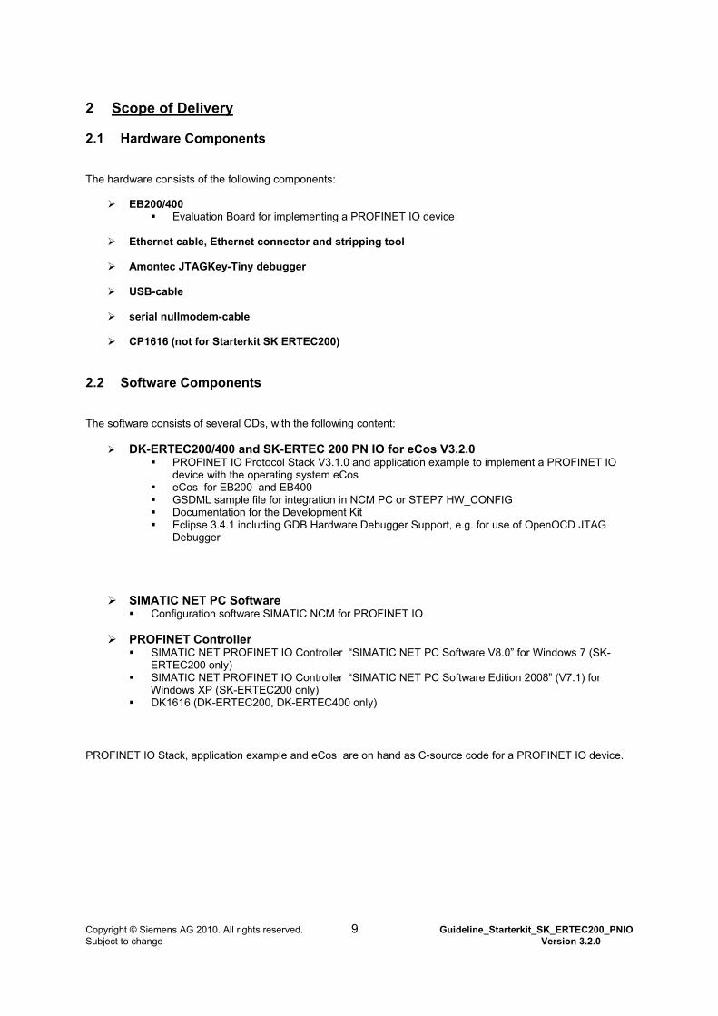
The hardware consists of the following components:
EB200/400 Evaluation Board for implementing a PROFINET IO device
Ethernet cable, Ethernet connector and stripping tool
Amontec JTAGKey-Tiny debugger
USB-cable
serial nullmodem-cable
CP1616 (not for Starterkit SK ERTEC200)
2.2 Software Components
The software consists of several CDs, with the following content:
DK-ERTEC200/400 and SK-ERTEC 200 PN IO for eCos V3.2.0 PROFINET IO Protocol Stack V3.1.0 and application example to implement a PROFINET IO
device with the operating system eCos eCos for EB200 and EB400 GSDML sample file for integration in NCM PC or STEP7 HW_CONFIG Documentation for the Development Kit Eclipse 3.4.1 including GDB Hardware Debugger Support, e.g. for use of OpenOCD JTAG
Debugger
SIMATIC NET PC Software
Configuration software SIMATIC NCM for PROFINET IO
PROFINET Controller SIMATIC NET PROFINET IO Controller “SIMATIC NET PC Software V8.0” for Windows 7 (SK-
ERTEC200 only) SIMATIC NET PROFINET IO Controller “SIMATIC NET PC Software Edition 2008” (V7.1) for
Windows XP (SK-ERTEC200 only) DK1616 (DK-ERTEC200, DK-ERTEC400 only)
PROFINET IO Stack, application example and eCos are on hand as C-source code for a PROFINET IO device.
Copyright © Siemens AG 2010. All rights reserved. 9 Guideline_Starterkit_SK_ERTEC200_PNIO Subject to change Version 3.2.0
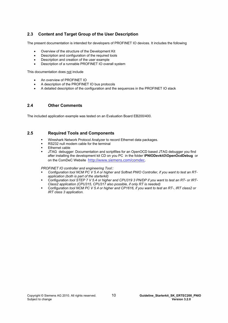
2.3 Content and Target Group of the User Description
The present documentation is intended for developers of PROFINET IO devices. It includes the following
Overview of the structure of the Development Kit Description and configuration of the required tools Description and creation of the user example Description of a runnable PROFINET IO overall system
This documentation does not include
An overview of PROFINET IO A description of the PROFINET IO bus protocols A detailed description of the configuration and the sequences in the PROFINET IO stack
2.4 Other Comments
The included application example was tested on an Evaluation Board EB200/400.
2.5 Required Tools and Components
Wireshark Network Protocol Analyzer to record Ethernet data packages. RS232 null modem cable for the terminal Ethernet cable JTAG debugger: Documentation and scriptfiles for an OpenOCD based JTAG debugger you find
after installing the development kit CD on you PC in the folder \PNIODevkit3\OpenOcdDebug or on the ComDeC Website http://www.siemens.com/comdec.
PROFINET IO controller and engineering Tool:: Configuration tool NCM PC V 5.4 or higher and Softnet PNIO Controller, if you want to test an RT-
application (both is part of the starterkit) Configuration tool STEP 7 V 5.4 or higher and CPU319 3 PN/DP if you want to test an RT- or IRT-
Class2 application (CPU315, CPU317 also possible, if only RT is needed) Configuration tool NCM PC V 5.4 or higher and CP1616, if you want to test an RT-, IRT class2 or
IRT class 3 application.
Copyright © Siemens AG 2010. All rights reserved. 10 Guideline_Starterkit_SK_ERTEC200_PNIO Subject to change Version 3.2.0
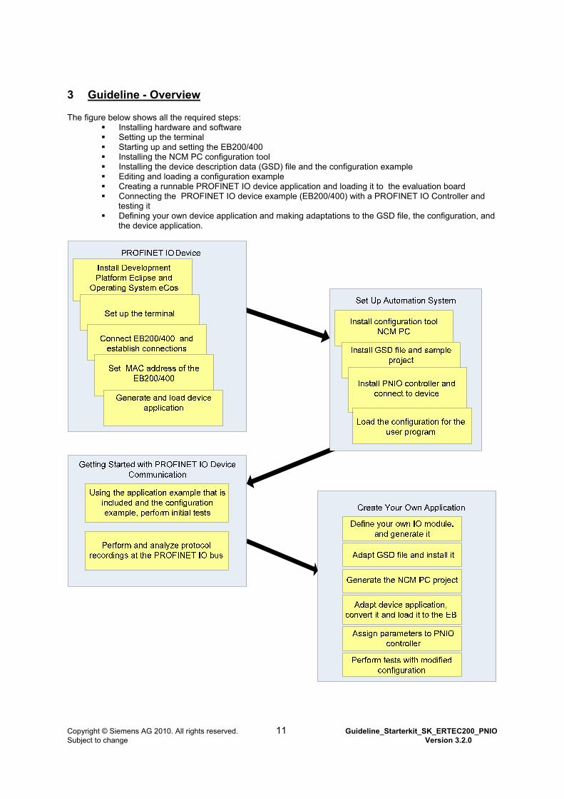
3 Guideline - Overview
The figure below shows all the required steps: Installing hardware and software Setting up the terminal Starting up and setting the EB200/400 Installing the NCM PC configuration tool Installing the device description data (GSD) file and the configuration example Editing and loading a configuration example Creating a runnable PROFINET IO device application and loading it to the evaluation board Connecting the PROFINET IO device example (EB200/400) with a PROFINET IO Controller and
testing it Defining your own device application and making adaptations to the GSD file, the configuration, and
the device application.
Copyright © Siemens AG 2010. All rights reserved. 11 Guideline_Starterkit_SK_ERTEC200_PNIO Subject to change Version 3.2.0
4 Setting Up the PROFINET IO Device To create a PROFINET IO device, first the operating system eCos has to be installed on a Windows PC, together with the PROFINET IO device stack and the device application. We recommend the development platform Eclipse which is described in this guideline. If you should use another development platform, you have to perform the required adaptations yourself.
All notes in the chapters below regarding settings and installation refer to the Evaluation Board EB200 and EB400.
Note regarding the description below:
All installation steps for eCos, PROFINET IO stack and eclipse (internet version) are shown in video tutorials. The videos are located on the CD.
4.1 Installing and Setting Up the Operating System eCos and PROFINET IO Stack The operating system eCos is a “Open Source” software which is free of license fee. Note: Ecos is under GNU General >Public License V2 (or later) with a special exception regarding copyleft effect:
As a special exception, if other files instantiate templates or use macros or inline functions from this file, or you compile this file and link it with other works to produce a work based on this file, this file does not by itself cause the resulting work to be covered by the GNU General Public License. However the source code for this file must still be made available in accordance with section (3) of the GNU General Public License. This exception does not invalidate any other reasons why a work based on this file might be covered by the GNU General Public License.
For use and pass on of eCos this conditions and further license conditions must be satisfied. In the file Readme_OSS you find a list of license conditions in the chapter for eCos. This file is stored on the SK- ERTEC 200 PN IO for eCos V3.1.0 CD.
4.1.1 Performing the Installation
Step 1
Insert the development kit CD into your CD/DVD drive of your Windows PC.
Step 2
Start the installation by calling the batch file “Install.bat” in the root directory on the CD.
Copyright © Siemens AG 2010. All rights reserved. 12 Guideline_Starterkit_SK_ERTEC200_PNIO Subject to change Version 3.2.0
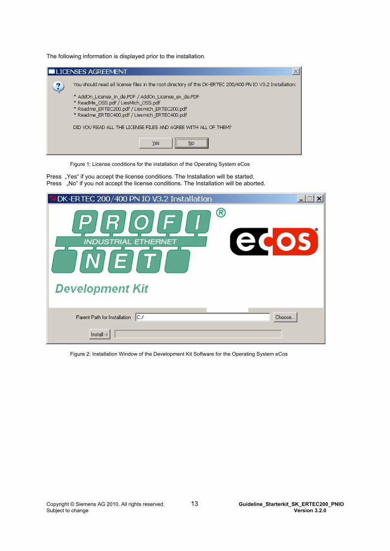
The following information is displayed prior to the installation.
Figure 1: License conditions for the installation of the Operating System eCos
Press „Yes“ if you accept the license conditions. The Installation will be started. Press „No“ if you not accept the license conditions. The Installation will be aborted.
Figure 2: Installation Window of the Development Kit Software for the Operating System eCos
Copyright © Siemens AG 2010. All rights reserved. 13 Guideline_Starterkit_SK_ERTEC200_PNIO Subject to change Version 3.2.0
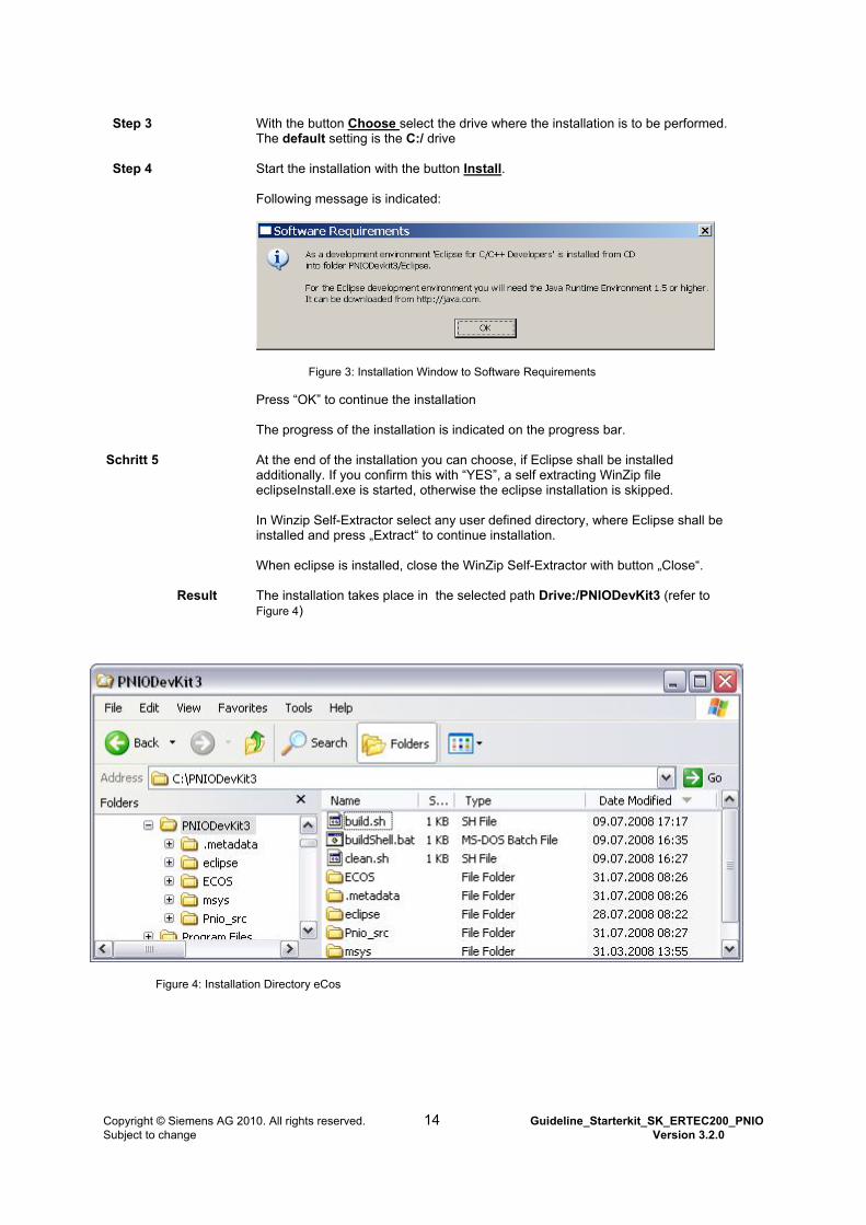
Step 3
With the button Choose select the drive where the installation is to be performed. The default setting is the C:/ drive
Step 4
Start the installation with the button Install. Following message is indicated:
Figure 3: Installation Window to Software Requirements
Press “OK” to continue the installation The progress of the installation is indicated on the progress bar.
Schritt 5
At the end of the installation you can choose, if Eclipse shall be installed additionally. If you confirm this with “YES”, a self extracting WinZip file eclipseInstall.exe is started, otherwise the eclipse installation is skipped. In Winzip Self-Extractor select any user defined directory, where Eclipse shall be installed and press „Extract“ to continue installation. When eclipse is installed, close the WinZip Self-Extractor with button „Close“.
Result The installation takes place in the selected path Drive:/PNIODevKit3 (refer to Figure 4)
Figure 4: Installation Directory eCos
Copyright © Siemens AG 2010. All rights reserved. 14 Guideline_Starterkit_SK_ERTEC200_PNIO Subject to change Version 3.2.0

4.2 eCos with Development Environment Eclipse
4.2.1 Installing the Development Platform Eclipse
To develop your own PROFINET IO device with the operating system eCos, we recommend using the development environment Eclipse. A ready to use eclipse version 3.4.1 including plugins for GDB hardware-debugger support (e.g. necessary for use of an OpenOCD JTAG debugger) you find on the product CD in the folder \tools\eclipse. It can be installed together with the development environment, the eclipse install-directory can be selected separately during installation. Because Eclipse does not use any entries in the Windows registry, it can be copied or moved after installation to any subdirectory. Eclipse is a “open source“ software that can also be downloaded from http://www.eclipse.org/downloads. Eclipse is free of license fee but with separate license conditions. Note for users of Windows 7: Parallel use of Eclipse and some antivirus programs may cause significant increase of time for building the software. In this case we recommend to exclude the PROFINET subdirectories from the virus check-up. How to exclude subdirectories from the virus check-up, please refer to the documentation of your antivirus program. Information about reference platforms for Eclipse you find after installation of Eclipse in the release notes, see file eclipse\readme\readme_eclipse.html.
Copyright © Siemens AG 2010. All rights reserved. 15 Guideline_Starterkit_SK_ERTEC200_PNIO Subject to change Version 3.2.0
4.2.2 Setting Up the Development Platform Eclipse
Precondition for starting Eclipse:
To start Eclipse IDE on your Windows PC, Java Runtime Environment JRE1.5 or higher has to be installed. If the software is not installed on your computer, download it from http://www.Java.com and install it. Installation instructions are provided there also.
Step 3
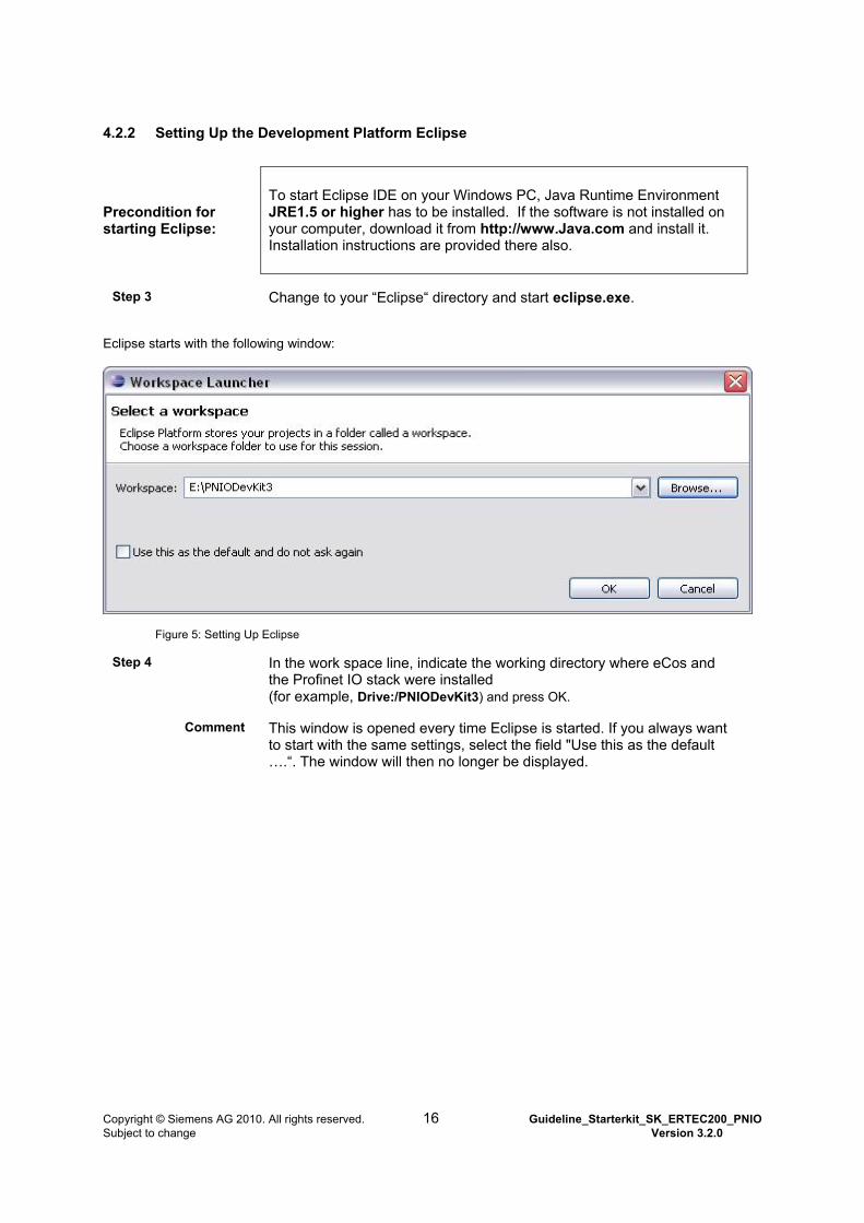
Change to your “Eclipse“ directory and start eclipse.exe.
Eclipse starts with the following window:
Figure 5: Setting Up Eclipse
Step 4
In the work space line, indicate the working directory where eCos and the Profinet IO stack were installed (for example, Drive:/PNIODevKit3) and press OK.
Comment This window is opened every time Eclipse is started. If you always want to start with the same settings, select the field "Use this as the default ….“. The window will then no longer be displayed.
Copyright © Siemens AG 2010. All rights reserved. 16 Guideline_Starterkit_SK_ERTEC200_PNIO Subject to change Version 3.2.0
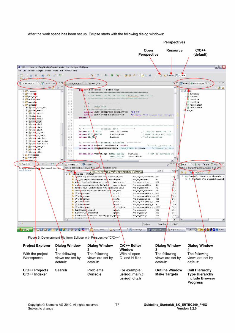
After the work space has been set up, Eclipse starts with the following dialog windows:
Perspectives
Open Perspective
Resource
C/C++
(default)
Figure 6: Development Platform Eclipse with Perspective "C/C++“
Project Explorer Dialog Window 1
Dialog Window 2
C/C++ Editor Window
Dialog Window 3
Dialog Window 4
With the project Workspaces
The following views are set by default:
The following views are set by default:
With all open C- and H-files
The following views are set by default:
The following views are set by default:
C/C++ Projects C/C++ Indexer
Search
Problems Console
For example: usriod_main.c usriod_cfg.h
Outline Window Make Targets
Call Hierarchy Type Hierarchy Include Browser Progress
Copyright © Siemens AG 2010. All rights reserved. 17 Guideline_Starterkit_SK_ERTEC200_PNIO Subject to change Version 3.2.0
You can change the standard setting and the perspectives any time, or add views and perspectives.
Adding Views In the menu bar, press the button <Windows> <Show View> <Others>. Select the view you want and press OK. The view is now displayed in a dialog window. You can now move the view, as described below.
Moving Views Select the view you want to move, and drag it to the desired dialog window.
Adding Perspectives Select the button <Open Perspective> and select the perspective you want to add. The selected perspective is then displayed as a symbol (refer to Figure 6 upper right "Perspectives“).
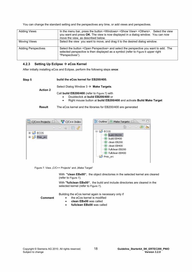
4.2.3 Setting Up Eclipse eCos Kernel
After initially installing eCos and Eclipse, perform the following steps once:
Step 5 build the eCos kernel for EB200/400.
Action 2
Select Dialog Window 3 Make Targets. Call build EB200/400 (refer to Figure 7) with
Doubleclick at build EB200/400 or Right mouse button at build EB200/400 and activate Build Make Target
Result
The eCos kernel and the libraries for EB200/400 are generated
Figure 7: View „C/C++ Projects“ and „Make Target“
With "clean EBx00“, the object directories in the selected kernel are cleared (refer to Figure 7).
With "fullclean EBx00“, the build and include directories are cleared in the selected kernel (refer to Figure 7).
Comment
Building the eCos kernel again is necessary only if
the eCos kernel is modified clean EBx00 was called fullclean EBx00 was called
Copyright © Siemens AG 2010. All rights reserved. 18 Guideline_Starterkit_SK_ERTEC200_PNIO Subject to change Version 3.2.0
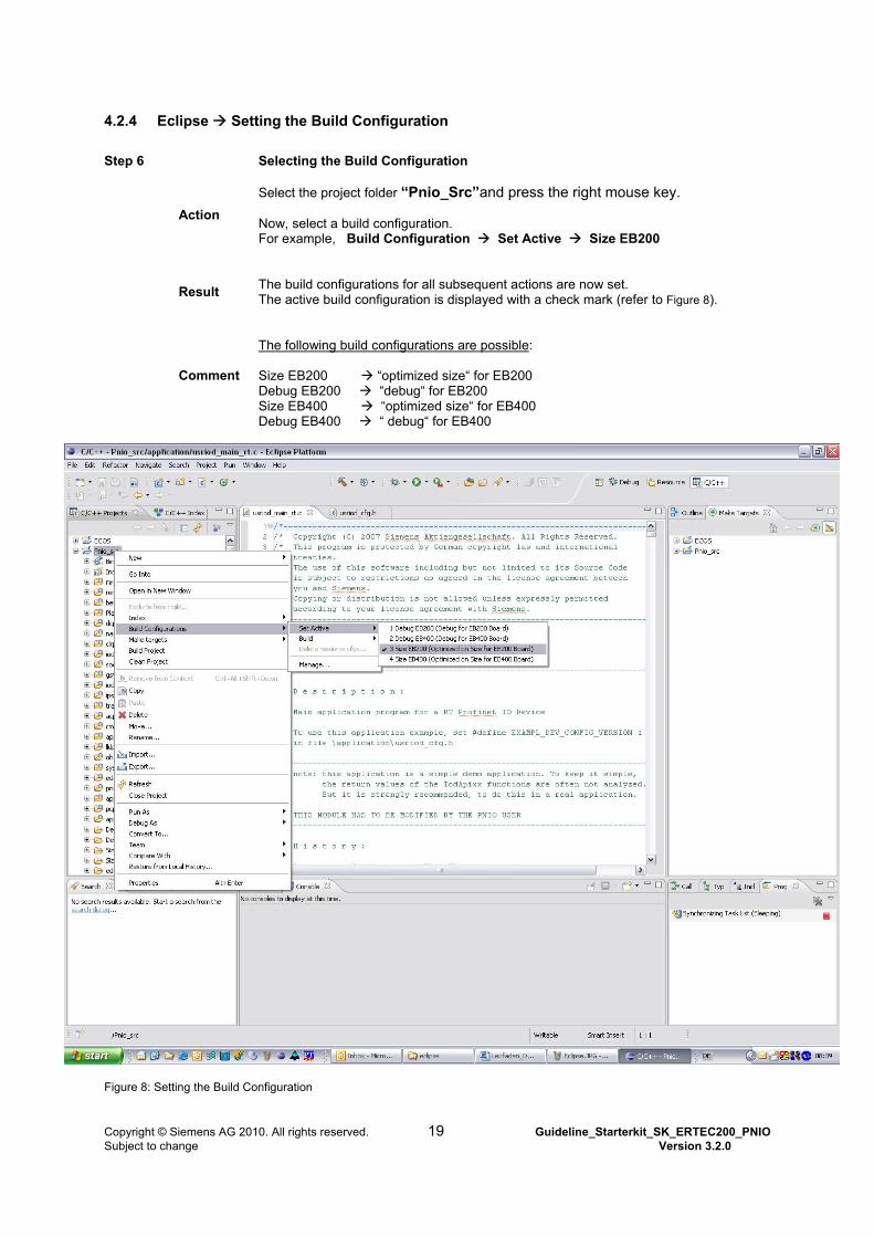
4.2.4 Eclipse Setting the Build Configuration
Step 6 Selecting the Build Configuration
Action
Select the project folder “Pnio_Src”and press the right mouse key. Now, select a build configuration. For example, Build Configuration Set Active Size EB200
Result
The build configurations for all subsequent actions are now set. The active build configuration is displayed with a check mark (refer to Figure 8).
Comment
The following build configurations are possible: Size EB200 “optimized size“ for EB200 Debug EB200 “debug“ for EB200 Size EB400 “optimized size“ for EB400 Debug EB400 “ debug“ for EB400
Figure 8: Setting the Build Configuration
Copyright © Siemens AG 2010. All rights reserved. 19 Guideline_Starterkit_SK_ERTEC200_PNIO Subject to change Version 3.2.0
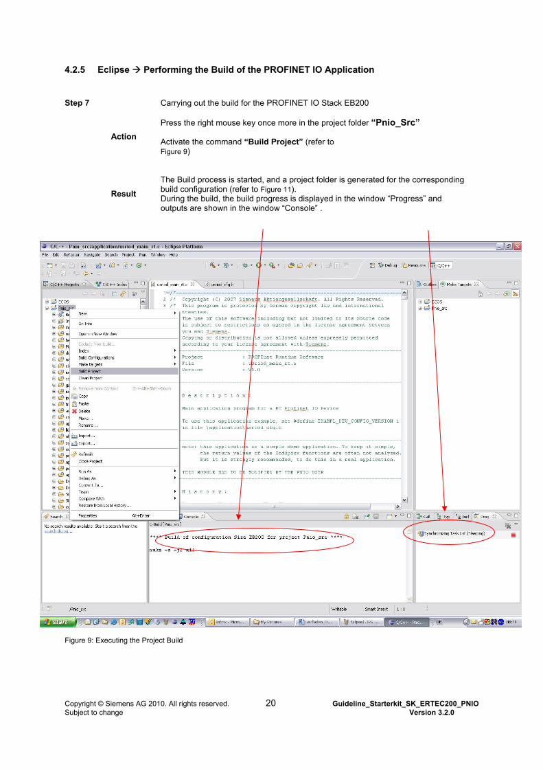
4.2.5 Eclipse Performing the Build of the PROFINET IO Application
Step 7 Carrying out the build for the PROFINET IO Stack EB200
Action
Press the right mouse key once more in the project folder “Pnio_Src” Activate the command “Build Project” (refer to Figure 9)
Result
The Build process is started, and a project folder is generated for the corresponding build configuration (refer to Figure 11). During the build, the build progress is displayed in the window “Progress” and outputs are shown in the window “Console” .
Figure 9: Executing the Project Build
Copyright © Siemens AG 2010. All rights reserved. 20 Guideline_Starterkit_SK_ERTEC200_PNIO Subject to change Version 3.2.0
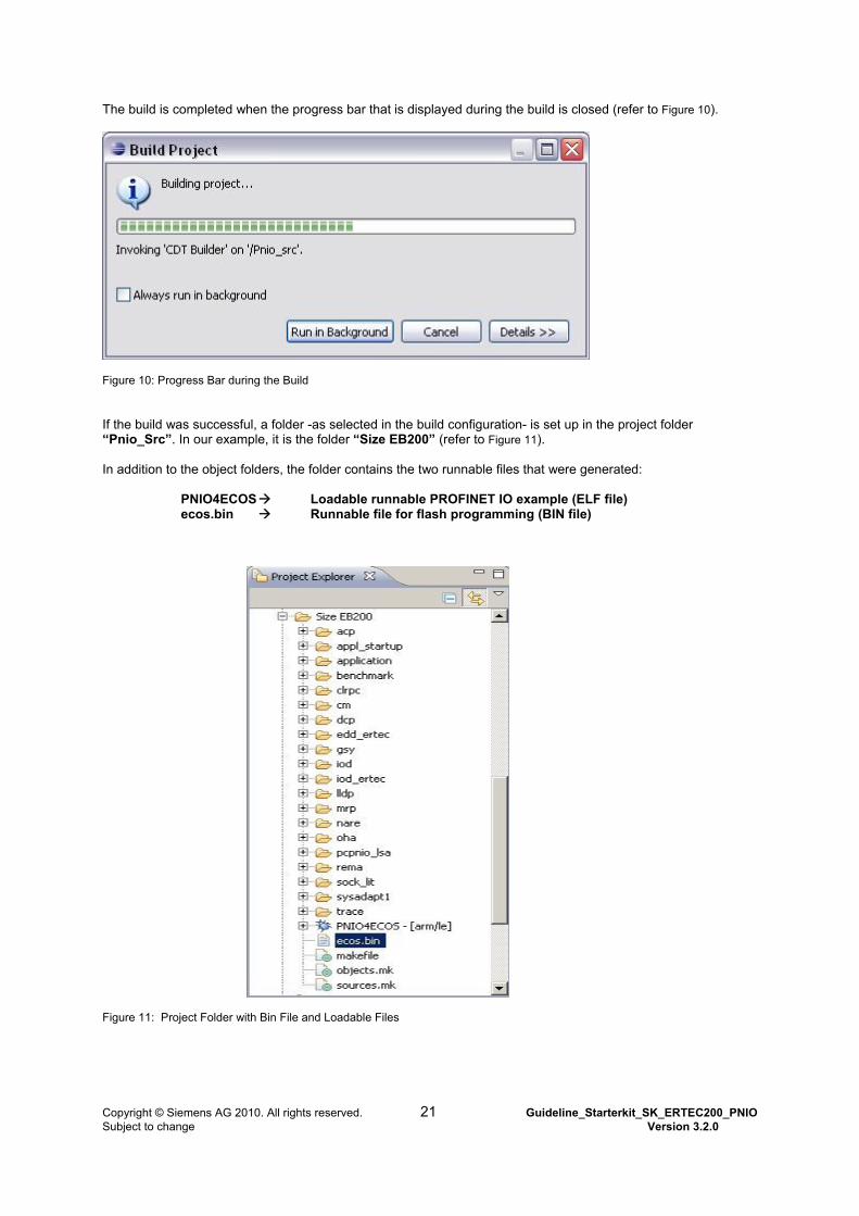
The build is completed when the progress bar that is displayed during the build is closed (refer to Figure 10).
Figure 10: Progress Bar during the Build If the build was successful, a folder -as selected in the build configuration- is set up in the project folder “Pnio_Src”. In our example, it is the folder “Size EB200” (refer to Figure 11). In addition to the object folders, the folder contains the two runnable files that were generated: PNIO4ECOS Loadable runnable PROFINET IO example (ELF file) ecos.bin Runnable file for flash programming (BIN file)
Figure 11: Project Folder with Bin File and Loadable Files
Copyright © Siemens AG 2010. All rights reserved. 21 Guideline_Starterkit_SK_ERTEC200_PNIO Subject to change Version 3.2.0
4.2.6 Editing the Application Example
The folder “Pnio_Src“ includes the folder “application“ with various examples for a PROFINET IO device. The following PROFINET IO examples can be selected:
Example Value Applications file RT Class 1, IRT Class 2 or IRT Class 3 example for ERTEC200/400
1 Usriod_main.c
DBAI example (direct buffer access interface) 2 Usriod_main_dbai.c A sample application is selected in the file “usriod_cfg.h“ in the folder “application“. The RT/IRT example is set Default with: #define EXAMPL_DEV_CONFIG_VERSION 1 The RT/IRT example includes the following PROFINET IO Device functions:
Slot 1 64 Byte Input Module Slot 2 64 Byte Output Module Various module-related diagnoses Process alarm I&M 0 function
If you make changes for your PROFINET IO device functions in the application folder, you have to carry out the following steps:
Step 1
Make all necessary changes in the application files, and save the modified files.
Step 2 Select the project folder “Pnio Src” and press the right mouse key
Action Activate the “Build” command (refer to Figure 9)
Result The Build is started, and all modified files are converted. After the Build is completed, the loadable PROFINET IO device example (PNIO4COS) and the object file (ecos.bin) are regenerated (refer to Figure 11).
Copyright © Siemens AG 2010. All rights reserved. 22 Guideline_Starterkit_SK_ERTEC200_PNIO Subject to change Version 3.2.0
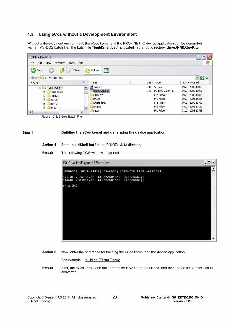
4.3 Using eCos without a Development Environment Without a development environment, the eCos kernel and the PROFINET IO device application can be generated with an MS-DOS batch file. The batch file “buildShell.bat“ is located in the root directory drive:/PNIODevKit3.
Figure 12: MS-Dos Batch File
Step 1 Building the eCos kernel and generating the device application.
Action 1
Start “buildShell.bat“ in the PNIODevKit3 directory
Result
The following DOS window is opened
Action 2
Now, enter the command for building the eCos kernel and the device application. For example, ./build.sh EB200 Debug
Result
First, the eCos kernel and the libraries for EB200 are generated, and then the device application is converted.
Copyright © Siemens AG 2010. All rights reserved. 23 Guideline_Starterkit_SK_ERTEC200_PNIO Subject to change Version 3.2.0
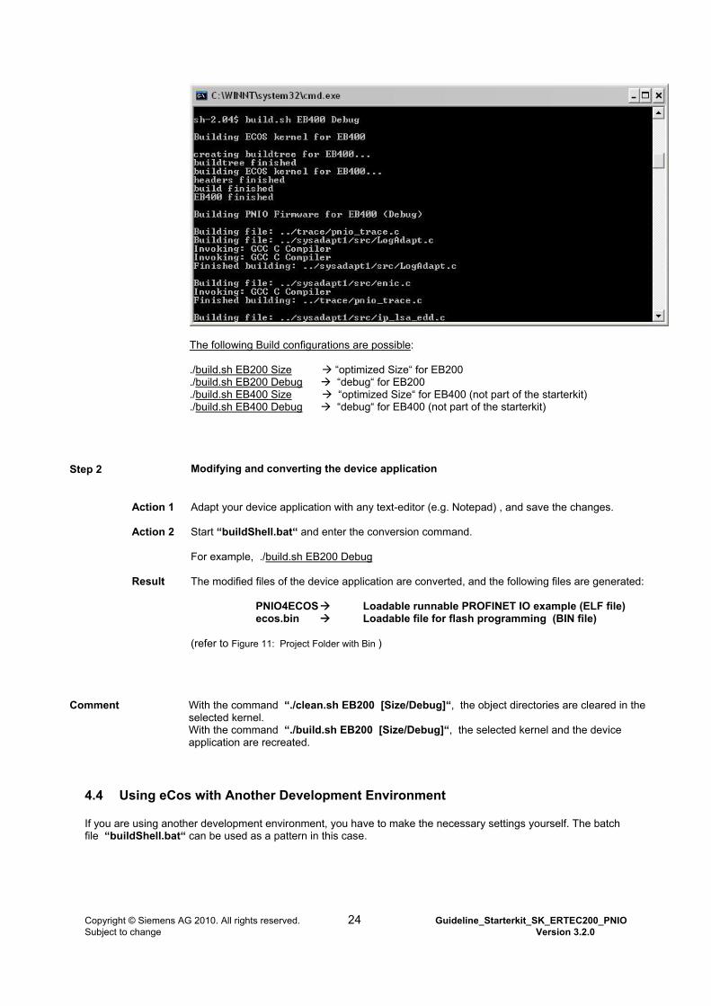
The following Build configurations are possible: ./build.sh EB200 Size “optimized Size“ for EB200 ./build.sh EB200 Debug “debug“ for EB200 ./build.sh EB400 Size “optimized Size“ for EB400 (not part of the starterkit) ./build.sh EB400 Debug “debug“ for EB400 (not part of the starterkit)
Step 2 Modifying and converting the device application
Action 1
Adapt your device application with any text-editor (e.g. Notepad) , and save the changes.
Action 2
Start “buildShell.bat“ and enter the conversion command. For example, ./build.sh EB200 Debug
Result
The modified files of the device application are converted, and the following files are generated: PNIO4ECOS Loadable runnable PROFINET IO example (ELF file) ecos.bin Loadable file for flash programming (BIN file) (refer to Figure 11: Project Folder with Bin )
Comment
With the command “./clean.sh EB200 [Size/Debug]“, the object directories are cleared in the selected kernel. With the command “./build.sh EB200 [Size/Debug]“, the selected kernel and the device application are recreated.
4.4 Using eCos with Another Development Environment If you are using another development environment, you have to make the necessary settings yourself. The batch file “buildShell.bat“ can be used as a pattern in this case.
Copyright © Siemens AG 2010. All rights reserved. 24 Guideline_Starterkit_SK_ERTEC200_PNIO Subject to change Version 3.2.0
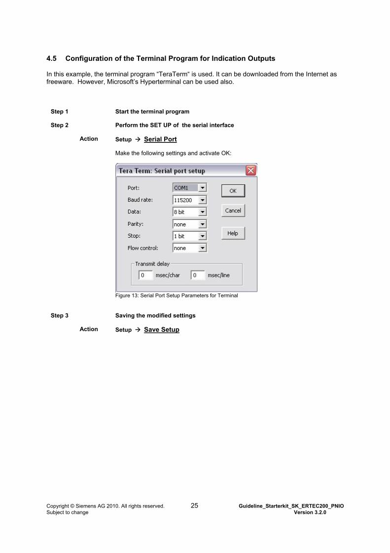
4.5 Configuration of the Terminal Program for Indication Outputs
In this example, the terminal program “TeraTerm“ is used. It can be downloaded from the Internet as freeware. However, Microsoft’s Hyperterminal can be used also.
Step 1
Start the terminal program
Step 2 Perform the SET UP of the serial interface
Action Setup Serial Port Make the following settings and activate OK:
Figure 13: Serial Port Setup Parameters for Terminal
Step 3
Saving the modified settings
Action Setup Save Setup
Copyright © Siemens AG 2010. All rights reserved. 25 Guideline_Starterkit_SK_ERTEC200_PNIO Subject to change Version 3.2.0
4.6 Starting Up the EB200/400
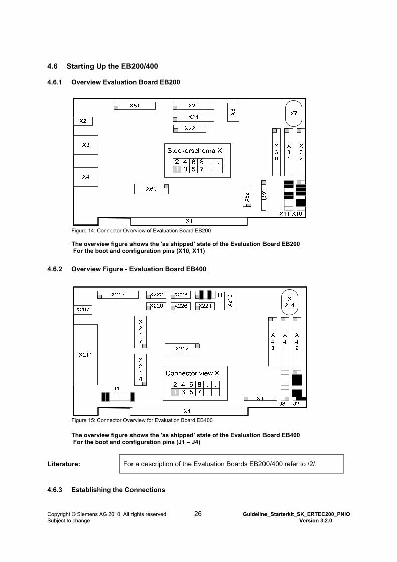
4.6.1 Overview Evaluation Board EB200
Figure 14: Connector Overview of Evaluation Board EB200 The overview figure shows the 'as shipped’ state of the Evaluation Board EB200 For the boot and configuration pins (X10, X11)
4.6.2 Overview Figure - Evaluation Board EB400
Figure 15: Connector Overview for Evaluation Board EB400
The overview figure shows the 'as shipped’ state of the Evaluation Board EB400 For the boot and configuration pins (J1 – J4)
Literature: For a description of the Evaluation Boards EB200/400 refer to /2/.
4.6.3 Establishing the Connections
Copyright © Siemens AG 2010. All rights reserved. 26 Guideline_Starterkit_SK_ERTEC200_PNIO Subject to change Version 3.2.0
Step 1
The following adaptations have to be made for the Evaluation Board EB200 to operate the plug-in power supply:
Action 1 Connect the plug-in power supply to the connector for the external DC voltage supply (X2 -- EB200/ X207 – EB400).
Step 2
Connect a free COM interface on your PC to the RS232 port of the EB200 (refer to Terminal Connection in Figure 17)
Action Connect the free COM port to the RS-232 port (X7 -- EB200/ X214 – EB400) of the Evaluation port.
Comment Use a null modem cable for the serial connection
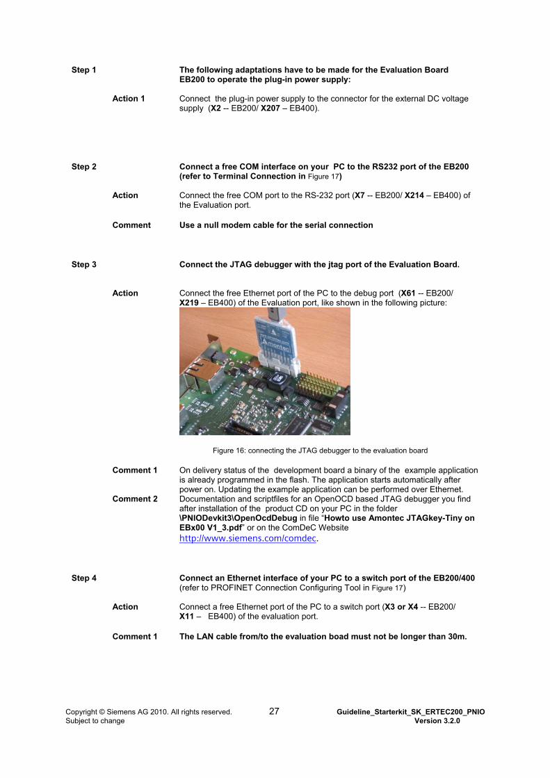
Step 3
Connect the JTAG debugger with the jtag port of the Evaluation Board.
Action Connect the free Ethernet port of the PC to the debug port (X61 -- EB200/ X219 – EB400) of the Evaluation port, like shown in the following picture:
Figure 16: connecting the JTAG debugger to the evaluation board
Comment 1 On delivery status of the development board a binary of the example application is already programmed in the flash. The application starts automatically after power on. Updating the example application can be performed over Ethernet.
Comment 2 Documentation and scriptfiles for an OpenOCD based JTAG debugger you find after installation of the product CD on your PC in the folder \PNIODevkit3\OpenOcdDebug in file “Howto use Amontec JTAGkey-Tiny on EBx00 V1_3.pdf” or on the ComDeC Website http://www.siemens.com/comdec.
Step 4
Connect an Ethernet interface of your PC to a switch port of the EB200/400 (refer to PROFINET Connection Configuring Tool in Figure 17)
Action Connect a free Ethernet port of the PC to a switch port (X3 or X4 -- EB200/ X11 – EB400) of the evaluation port.
Comment 1 The LAN cable from/to the evaluation boad must not be longer than 30m.
Copyright © Siemens AG 2010. All rights reserved. 27 Guideline_Starterkit_SK_ERTEC200_PNIO Subject to change Version 3.2.0
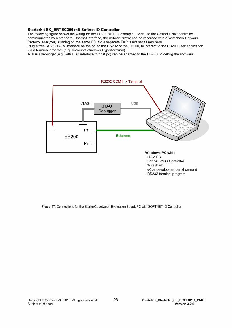
Starterkit SK_ERTEC200 mit Softnet IO Controller The following figure shows the wiring for the PROFINET IO example. Because the Softnet PNIO controller communicates by a standard Ethernet interface, the network traffic can be recorded with a Wireshark Network Protocol Analyzer, running on the same PC. So a separate TAP is not necessary here. Plug a free RS232 COM interface on the pc to the RS232 of the EB200, to interact to the EB200 user application via a terminal program (e.g. Microsoft Windows Hyperterminal). A JTAG debugger (e.g. with USB interface to host pc) can be adapted to the EB200, to debug the software.
EB200P2
P1
RS232 COM1 Terminal
Windows PC with NCM PC Softnet PNIO Controller Wireshark eCos development environment RS232 terminal program
Ethernet
JTAG Debugger
JTAG USB
Figure 17: Connections for the StarterKit between Evaluation Board, PC with SOFTNET IO Controller
Copyright © Siemens AG 2010. All rights reserved. 28 Guideline_Starterkit_SK_ERTEC200_PNIO Subject to change Version 3.2.0
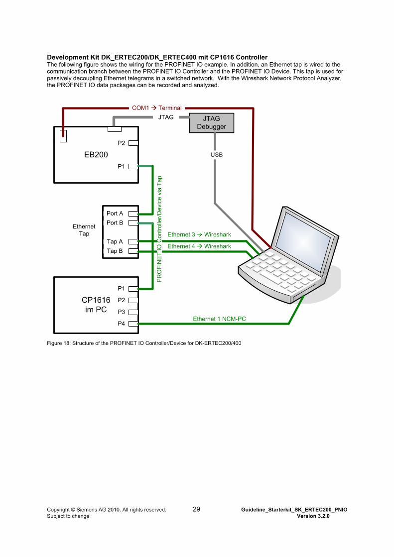
Development Kit DK_ERTEC200/DK_ERTEC400 mit CP1616 Controller The following figure shows the wiring for the PROFINET IO example. In addition, an Ethernet tap is wired to the communication branch between the PROFINET IO Controller and the PROFINET IO Device. This tap is used for passively decoupling Ethernet telegrams in a switched network. With the Wireshark Network Protocol Analyzer, the PROFINET IO data packages can be recorded and analyzed.
EB200
CP1616 im PC
Ethernet Tap
Port A
Port B
Tap A
Tap B
P1
P2
P3
P4
P1
P2
Ethernet 3 Wireshark
Ethernet 4 Wireshark
Ethernet 1 NCM-PC
COM1 Terminal
PR
OF
INE
T I
O C
ontr
olle
r/D
evic
e vi
a T
ap
JTAG Debugger
JTAG
USB
Figure 18: Structure of the PROFINET IO Controller/Device for DK-ERTEC200/400
Copyright © Siemens AG 2010. All rights reserved. 29 Guideline_Starterkit_SK_ERTEC200_PNIO Subject to change Version 3.2.0
4.6.4 Setting the MAC Address
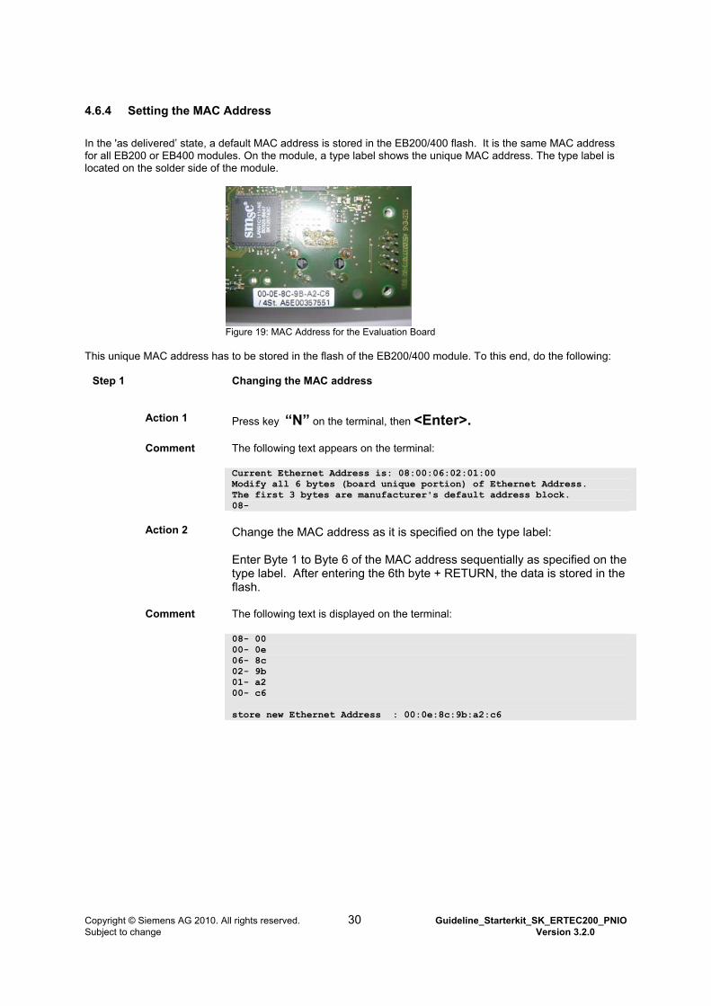
In the 'as delivered’ state, a default MAC address is stored in the EB200/400 flash. It is the same MAC address for all EB200 or EB400 modules. On the module, a type label shows the unique MAC address. The type label is located on the solder side of the module.
Figure 19: MAC Address for the Evaluation Board
This unique MAC address has to be stored in the flash of the EB200/400 module. To this end, do the following:
Step 1 Changing the MAC address
Action 1 Press key “N” on the terminal, then <Enter>.
Comment The following text appears on the terminal:
Current Ethernet Address is: 08:00:06:02:01:00 Modify all 6 bytes (board unique portion) of Ethernet Address. The first 3 bytes are manufacturer's default address block. 08-
Action 2
Change the MAC address as it is specified on the type label: Enter Byte 1 to Byte 6 of the MAC address sequentially as specified on the type label. After entering the 6th byte + RETURN, the data is stored in the flash.
Comment The following text is displayed on the terminal:
08- 00 00- 0e 06- 8c 02- 9b 01- a2 00- c6 store new Ethernet Address : 00:0e:8c:9b:a2:c6
Copyright © Siemens AG 2010. All rights reserved. 30 Guideline_Starterkit_SK_ERTEC200_PNIO Subject to change Version 3.2.0

5 Setting Up the Automation System The following chapter describes how to set up a PROFINET IO controller. If you are using a DK-ERTEC200/400 with CP1616 controller, please read chapter “Setting up the automation system for a CP1616 controller”. If you are using a SK-ERTEC200 with SOFTNET IO controller, please read chapter “Setting up the automation system for a SOFTNET IO controller”. If you want to use a SIMATIC CPU as a PROFINET IO controller, you have to use STEP7 as an engineering system. It is not part of the development kit. On Principle STEP7 is able to configure PC based PROFINET IO controllers CP1616 and SOFTNET IO. Note: STEP7 and NCM PC must not be installed on the same PC.
Copyright © Siemens AG 2010. All rights reserved. 31 Guideline_Starterkit_SK_ERTEC200_PNIO Subject to change Version 3.2.0
5.1 Set up the automation system for a CP1616 controller
5.1.1 Installing the Configuring Tool NCM
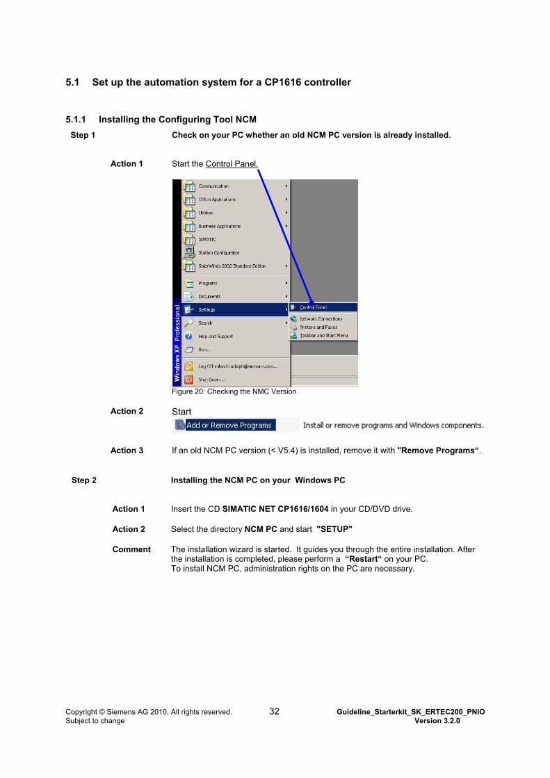
Step 1 Check on your PC whether an old NCM PC version is already installed.
Action 1 Start the Control Panel.
Figure 20: Checking the NMC Version
Action 2 Start
Action 3 If an old NCM PC version (< V5.4) is installed, remove it with "Remove Programs“.
Step 2 Installing the NCM PC on your Windows PC
Action 1 Insert the CD SIMATIC NET CP1616/1604 in your CD/DVD drive.
Action 2 Select the directory NCM PC and start "SETUP"
Comment The installation wizard is started. It guides you through the entire installation. After the installation is completed, please perform a “Restart“ on your PC. To install NCM PC, administration rights on the PC are necessary.
Copyright © Siemens AG 2010. All rights reserved. 32 Guideline_Starterkit_SK_ERTEC200_PNIO Subject to change Version 3.2.0
5.1.2 Inserting the CP1616 in a Windows PC and Installing the Hardware Driver
The following is provided on the included CD "DK-CP16xx PN IO“: the documents for installing the CP1616, the Windows driver for the CP1616, and the user application. Please read the installation instructions carefully prior to the installation.
Step 1 Inserting the CP1616 in a PCI slot of the Windows PC
Action 1 Power down the PC, and switch it off.
Action 2 Pull the power plug.
Action 3 Open the PC and insert the CP1616 in a free PCI slot. Handling unprotected modules has to be paid attention to.
Action 4 Close PC and plug in power plug.
Step 2
Install the Windows driver for the CP1616.
Action 1
Switch on the PC. Windows automatically recognizes the new hardware and asks for the required driver. Cancel the process.
Action 2
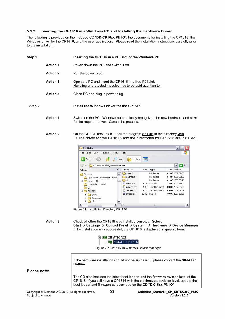
On the CD “CP16xx PN IO“, call the program SETUP in the directory WIN The driver for the CP1616 and the directories for CP1616 are installed.
Figure 21: Installation Directory CP1616
Action 3 Check whether the CP1616 was installed correctly. Select Start Settings Control Panel System Hardware Device Manager If the installation was successful, the CP1616 is displayed in graphic form:
Figure 22: CP1616 im Windows Device Manager
If the hardware installation should not be successful, please contact the SIMATIC Hotline.
Please note: The CD also includes the latest boot loader, and the firmware revision level of the CP1616. If you still have a CP1616 with the old firmware revision level, update the boot loader and firmware as described on the CD "DK16xx PN IO“.
Copyright © Siemens AG 2010. All rights reserved. 33 Guideline_Starterkit_SK_ERTEC200_PNIO Subject to change Version 3.2.0

5.1.3 Starting and Settin
fter installing the configuring tool NCM PC, a few settings have to be made. hese are:
ce“ for configuring
form the configuration and load to the CP1616
Step 1
Action CM PC with the Desktop Shortcut
g the NCM PC
AT
Set the Ethernet interface "PG/PC Interfa Load the GSD file and the bit map file to the hardware catalog
py configuration example from CD and open Co Per
5.1.3.1 Setting the Ethernet Interface
Start NCM PC and set interface.
N
or using the Start menu Start “Programs Simati SIMATIC NCM PC Manager”
Step 2
et PG/PC In
ction 1 NCM PC, select the menu Options Set PG/PC Interface (refer to Figure 23)
ction 2 elect TCP/IP(Auto) <free Ethernet Interface on PC> for the access point
c
terface. S
A In
A
Sbetween NCM PC and CP1616. In this example, it is the Ethernet interface D-Link
UB-E100 USB. OK accepts the settings. D
Copyright © Siemens AG 2010. All rights reserved. 34 Guideline_Starterkit_SK_ERTEC200_PNIO Subject to change Version 3.2.0
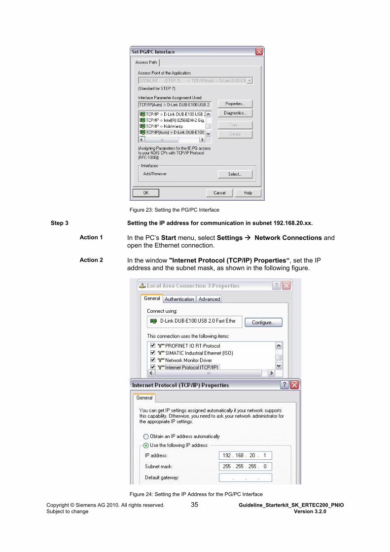
Figure 23: Setting the PG/PC Interface
Step 3 Setting the IP address for communication in subnet 192.168.20.xx.
Action 1 In the PC’s Start menu, select Settings Network Connections and
open the Ethernet connection.
Action 2 In the window "Internet Protocol (TCP/IP) Properties“, set the IP address and the subnet mask, as shown in the following figure.
Figure 24: Setting the IP Address for the PG/PC Interface
Copyright © Siemens AG 2010. All rights reserved. 35 Guideline_Starterkit_SK_ERTEC200_PNIO Subject to change Version 3.2.0
5.1.3.2 Editing the Project Example for PROFINET IO Device
The directory "NCM_PC“ on the CD DK-ERTEC 200 PN IO contains a complete NCM PC project -that matches the device application- for "Realtime Communication“ (RT). It includes the following:
The bus configuration with CP1616 IO Controller and PNIO Device The configuration of the inputs and outputs of the PNIO device
It is recommended using this example unchanged for the initial startup.
Step 1 Unzipping the project file for NCM PC.
Action Unzip the zip file to the work directory DRIVE:\……\Siemens\SIMATIC_NCM\s7proj.
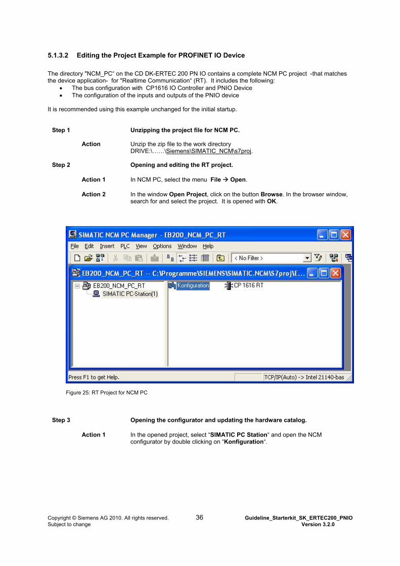
Step 2 Opening and editing the RT project.
Action 1 In NCM PC, select the menu File Open.
Action 2 In the window Open Project, click on the button Browse. In the browser window, search for and select the project. It is opened with OK.
Figure 25: RT Project for NCM PC
Step 3 Opening the configurator and updating the hardware catalog.
Action 1 In the opened project, select “SIMATIC PC Station“ and open the NCM configurator by double clicking on “Konfiguration“.
Copyright © Siemens AG 2010. All rights reserved. 36 Guideline_Starterkit_SK_ERTEC200_PNIO Subject to change Version 3.2.0
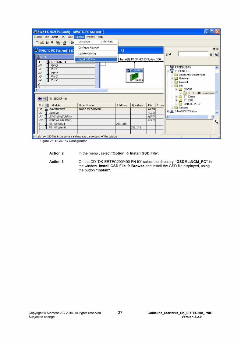
Figure 26: NCM PC Configurator
Action 2 In the menu , select “Option Install GSD File“.
Action 3 On the CD “DK-ERTEC200/400 PN IO“ select the directory “GSDML\NCM_PC“ in the window Install GSD File Browse and install the GSD file displayed, using the button “Install“.
Copyright © Siemens AG 2010. All rights reserved. 37 Guideline_Starterkit_SK_ERTEC200_PNIO Subject to change Version 3.2.0
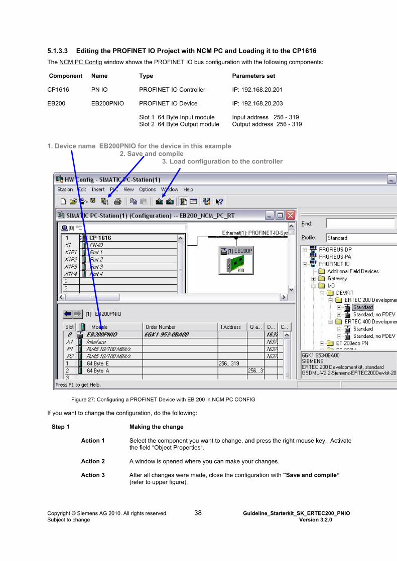
5.1.3.3 Editing the PROFINET IO Project with NCM PC and Loading it to the CP1616
The NCM PC Config window shows the PROFINET IO bus configuration with the following components: Component Name Type
Parameters set
CP1616 PN IO PROFINET IO Controller
IP: 192.168.20.201
EB200 EB200PNIO PROFINET IO Device
IP: 192.168.20.203
Slot 1 64 Byte Input module Slot 2 64 Byte Output module
Input address 256 - 319 Output address 256 - 319
1. Device name EB200PNIO for the device in this example
2. Save and compile 3. Load configuration to the controller
Figure 27: Configuring a PROFINET Device with EB 200 in NCM PC CONFIG
If you want to change the configuration, do the following:
Step 1 Making the change
Action 1 Select the component you want to change, and press the right mouse key. Activate the field “Object Properties“.
Action 2 A window is opened where you can make your changes.
Action 3 After all changes were made, close the configuration with "Save and compile“ (refer to upper figure).
Copyright © Siemens AG 2010. All rights reserved. 38 Guideline_Starterkit_SK_ERTEC200_PNIO Subject to change Version 3.2.0
Step 2 Downloading the configuration to Controller CP1616
Action 1 Connect all components as described in Section 4.7.3 (refer to Figure 17).
Action 2 Load the bus configuration to the CP1616 PROFINET IO Controller (refer to upper figure).
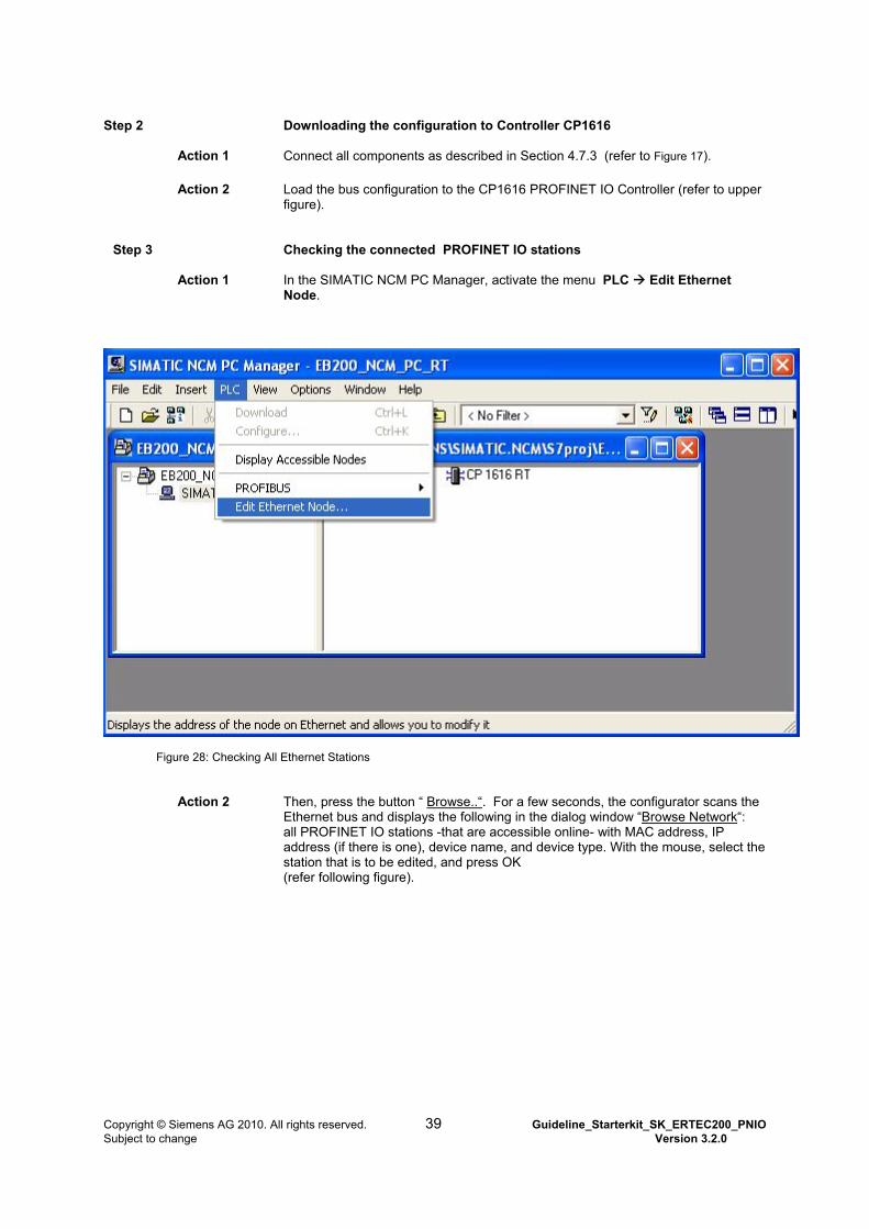
Step 3 Checking the connected PROFINET IO stations
Action 1 In the SIMATIC NCM PC Manager, activate the menu PLC Edit Ethernet
Node.
Figure 28: Checking All Ethernet Stations
Action 2 Then, press the button “ Browse..“. For a few seconds, the configurator scans the Ethernet bus and displays the following in the dialog window “Browse Network“: all PROFINET IO stations -that are accessible online- with MAC address, IP address (if there is one), device name, and device type. With the mouse, select the station that is to be edited, and press OK (refer following figure).
Copyright © Siemens AG 2010. All rights reserved. 39 Guideline_Starterkit_SK_ERTEC200_PNIO Subject to change Version 3.2.0
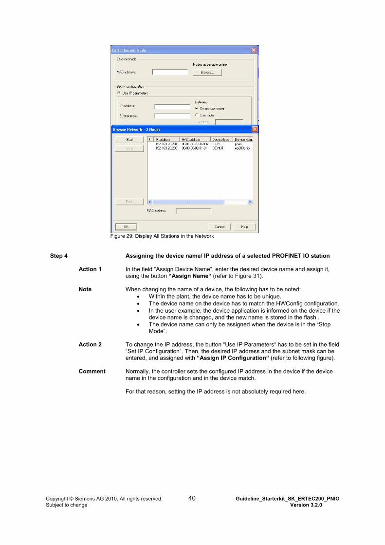
Figure 29: Display All Stations in the Network
Step 4 Assigning the device name/ IP address of a selected PROFINET IO station
Action 1 In the field “Assign Device Name“, enter the desired device name and assign it, using the button “Assign Name“ (refer to Figure 31).
Note When changing the name of a device, the following has to be noted: Within the plant, the device name has to be unique. The device name on the device has to match the HWConfig configuration. In the user example, the device application is informed on the device if the
device name is changed, and the new name is stored in the flash . The device name can only be assigned when the device is in the “Stop
Mode“.
Action 2 To change the IP address, the button “Use IP Parameters“ has to be set in the field “Set IP Configuration“. Then, the desired IP address and the subnet mask can be entered, and assigned with “Assign IP Configuration“ (refer to following figure).
Comment Normally, the controller sets the configured IP address in the device if the device name in the configuration and in the device match. For that reason, setting the IP address is not absolutely required here.
Copyright © Siemens AG 2010. All rights reserved. 40 Guideline_Starterkit_SK_ERTEC200_PNIO Subject to change Version 3.2.0
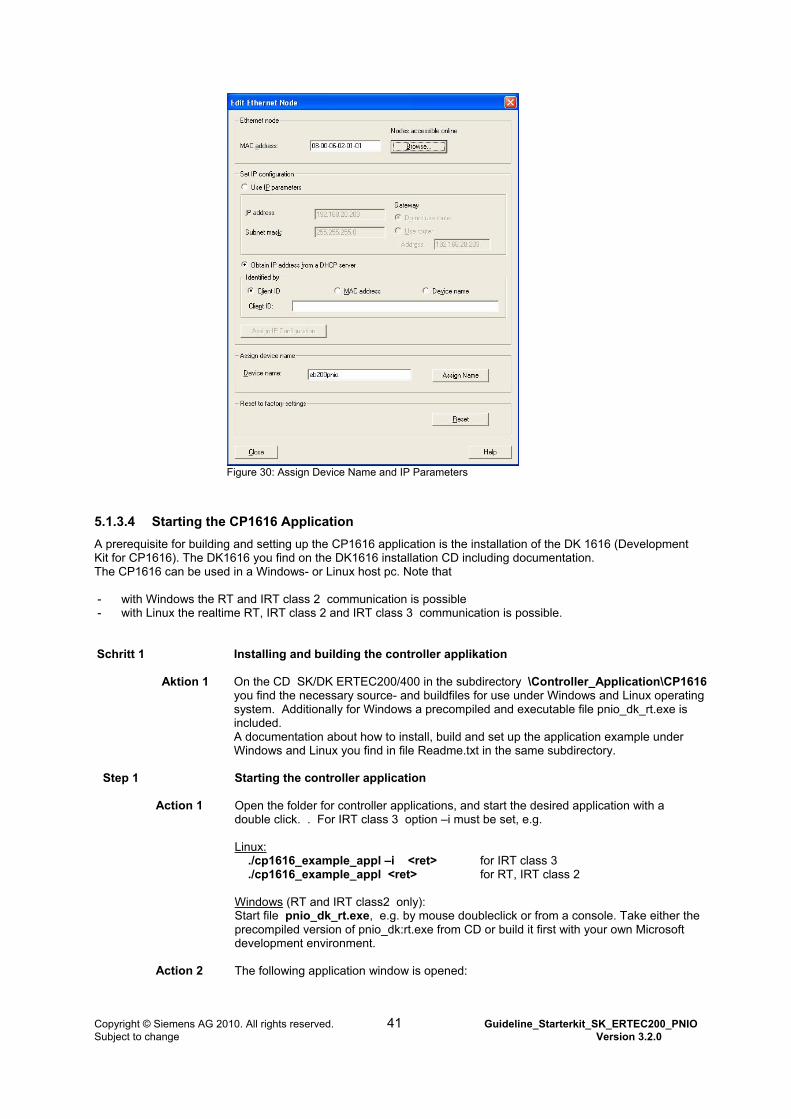
Figure 30: Assign Device Name and IP Parameters
5.1.3.4 Starting the CP1616 Application
A prerequisite for building and setting up the CP1616 application is the installation of the DK 1616 (Development Kit for CP1616). The DK1616 you find on the DK1616 installation CD including documentation. The CP1616 can be used in a Windows- or Linux host pc. Note that - with Windows the RT and IRT class 2 communication is possible - with Linux the realtime RT, IRT class 2 and IRT class 3 communication is possible. Schritt 1 Installing and building the controller applikation
Aktion 1 On the CD SK/DK ERTEC200/400 in the subdirectory \Controller_Application\CP1616
you find the necessary source- and buildfiles for use under Windows and Linux operating system. Additionally for Windows a precompiled and executable file pnio_dk_rt.exe is included. A documentation about how to install, build and set up the application example under Windows and Linux you find in file Readme.txt in the same subdirectory.
Step 1 Starting the controller application
Action 1 Open the folder for controller applications, and start the desired application with a
double click. . For IRT class 3 option –i must be set, e.g. Linux: ./cp1616_example_appl –i <ret> for IRT class 3 ./cp1616_example_appl <ret> for RT, IRT class 2 Windows (RT and IRT class2 only): Start file pnio_dk_rt.exe, e.g. by mouse doubleclick or from a console. Take either the precompiled version of pnio_dk:rt.exe from CD or build it first with your own Microsoft development environment.
Action 2 The following application window is opened:
Copyright © Siemens AG 2010. All rights reserved. 41 Guideline_Starterkit_SK_ERTEC200_PNIO Subject to change Version 3.2.0
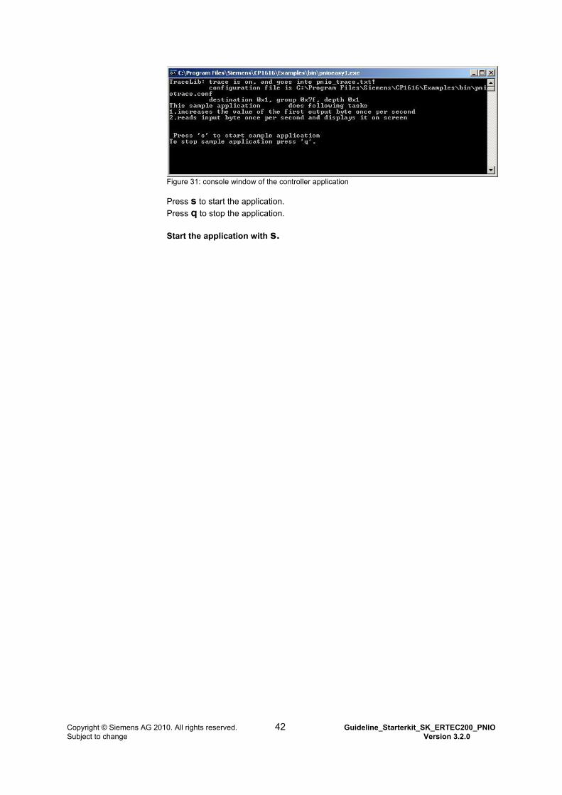
Figure 31: console window of the controller application
Press s to start the application.
Press q to stop the application.
Start the application with s.
Copyright © Siemens AG 2010. All rights reserved. 42 Guideline_Starterkit_SK_ERTEC200_PNIO Subject to change Version 3.2.0
5.2 Set up the automation system for a SOFTNET IO controller
5.2.1 Installing the Configuring Tool NCM
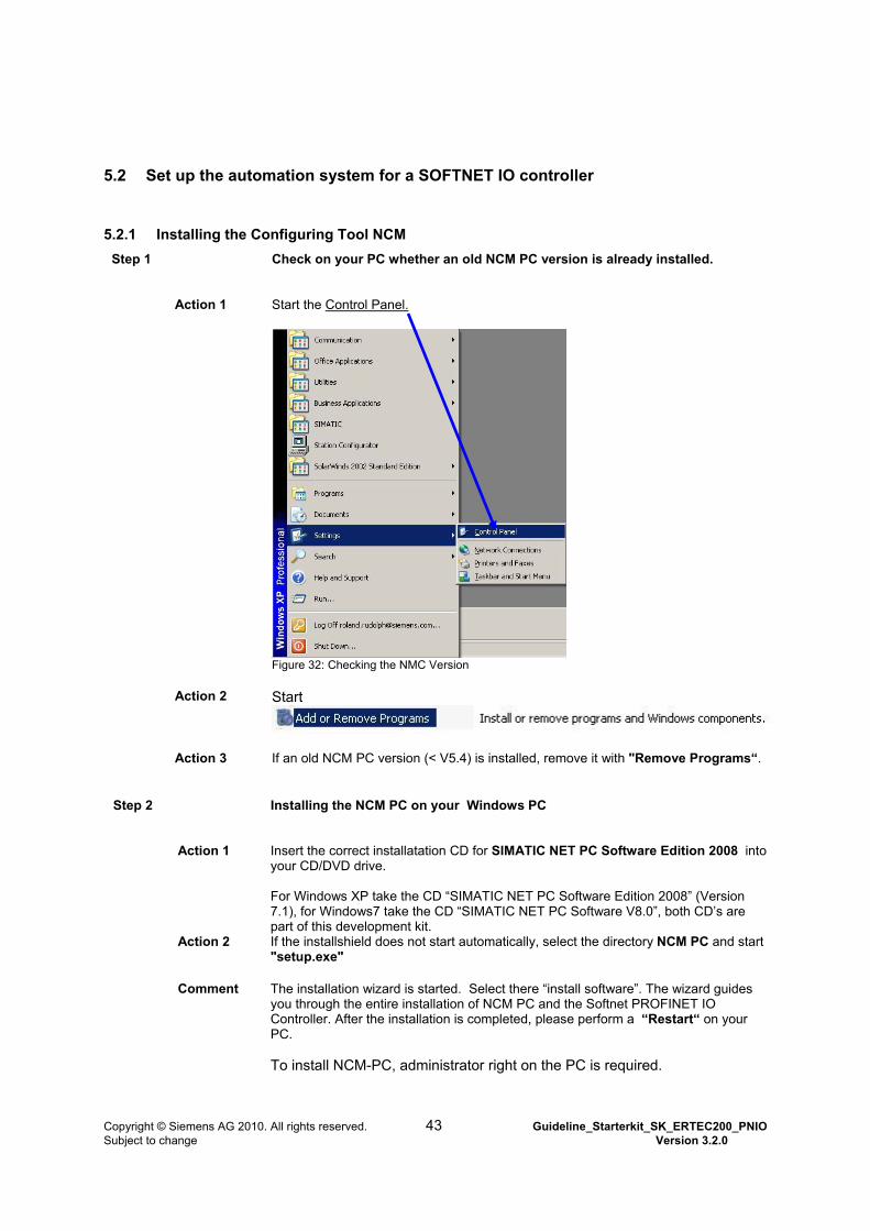
Step 1 Check on your PC whether an old NCM PC version is already installed.
Action 1 Start the Control Panel.
Figure 32: Checking the NMC Version
Action 2 Start
Action 3 If an old NCM PC version (< V5.4) is installed, remove it with "Remove Programs“.
Step 2 Installing the NCM PC on your Windows PC
Action 1 Insert the correct installatation CD for SIMATIC NET PC Software Edition 2008 into your CD/DVD drive. For Windows XP take the CD “SIMATIC NET PC Software Edition 2008” (Version 7.1), for Windows7 take the CD “SIMATIC NET PC Software V8.0”, both CD’s are part of this development kit.
Action 2 If the installshield does not start automatically, select the directory NCM PC and start "setup.exe"
Comment The installation wizard is started. Select there “install software”. The wizard guides you through the entire installation of NCM PC and the Softnet PROFINET IO Controller. After the installation is completed, please perform a “Restart“ on your PC. To install NCM-PC, administrator right on the PC is required.
Copyright © Siemens AG 2010. All rights reserved. 43 Guideline_Starterkit_SK_ERTEC200_PNIO Subject to change Version 3.2.0
5.2.2 Starting and Setting the NCM PC
After installing the configuring tool NCM PC, a few settings have to be made. These are:
Set the Ethernet interface "PG/PC Interface“ for configuring Load the GSD file and the bit map file to the hardware catalog Copy configuration example from CD, unzip and open it Perform the configuration of the Softnet PNIO controller start the PNIO controller example- application
5.2.2.1 Setting the Ethernet Interface
Step 1
Start NCM PC and set interface.
Action
NCM PC with the Desktop Shortcut
or using the Start menu Start “Programs Simatic SIMATIC NCM PC Manager”
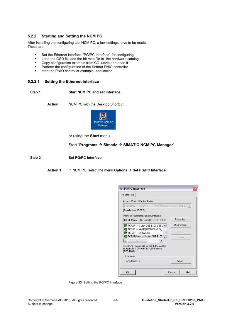
Step 2
Set PG/PC Interface.
Action 1
In NCM PC, select the menu Options Set PG/PC Interface
Figure 33: Setting the PG/PC Interface
Copyright © Siemens AG 2010. All rights reserved. 44 Guideline_Starterkit_SK_ERTEC200_PNIO Subject to change Version 3.2.0

Action 2 Select TCP/IP(Auto) <free Ethernet Interface on PC> for the access point between NCM PC and the PNIO controller. In this example, it is the Ethernet interface D-Link DUB-E100 USB. OK accepts the settings.
Step 3 Setting the IP address for communication in subnet 192.168.20.1. This corresponds to the NCM example configuration project. If you want to use another IP address, you have to adapt the configuration project.
Action 1 In the PC’s Start menu, select Settings Network Connections and open the Ethernet connection.
Figure 34: Setting the IP Address for the PG/PC Interface
Action 2 In the window "Internet Protocol (TCP/IP) Properties“, set the IP address and the subnet mask, as shown the figure above.
Copyright © Siemens AG 2010. All rights reserved. 45 Guideline_Starterkit_SK_ERTEC200_PNIO Subject to change Version 3.2.0
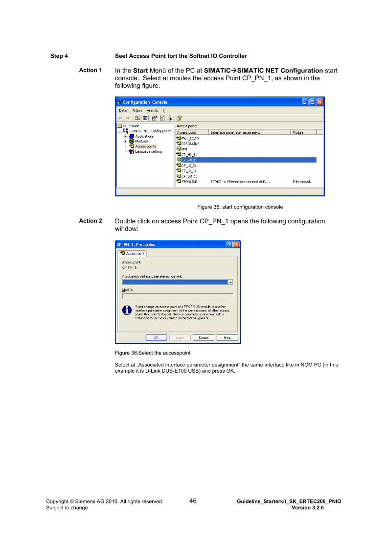
Step 4 Seet Access Point fort the Softnet IO Controller
Action 1 In the Start Menü of the PC at SIMATICSIMATIC NET Configuration start
console. Select at moules the access Point CP_PN_1, as shown in the following figure.
Figure 35: start configuration console
Action 2 Double click on access Point CP_PN_1 opens the following configuration window:
Figure 36:Select the accesspoint Select at „Associated interface parameter assignment“ the same interface like in NCM PC (in this example it is D-Link DUB-E100 USB) and press OK.
Copyright © Siemens AG 2010. All rights reserved. 46 Guideline_Starterkit_SK_ERTEC200_PNIO Subject to change Version 3.2.0
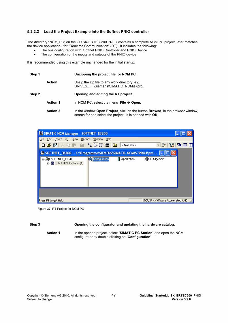
5.2.2.2 Load the Project Example into the Softnet PNIO controller
The directory "NCM_PC“ on the CD SK-ERTEC 200 PN IO contains a complete NCM PC project -that matches the device application- for "Realtime Communication“ (RT). It includes the following:
The bus configuration with Softnet PNIO Controller and PNIO Device The configuration of the inputs and outputs of the PNIO device
It is recommended using this example unchanged for the initial startup.
Step 1 Unzipping the project file for NCM PC.
Action Unzip the zip file to any work directory, e.g. DRIVE:\……\Siemens\SIMATIC_NCM\s7proj.
Step 2 Opening and editing the RT project.
Action 1 In NCM PC, select the menu File Open.
Action 2 In the window Open Project, click on the button Browse. In the browser window, search for and select the project. It is opened with OK.
Figure 37: RT Project for NCM PC
Step 3 Opening the configurator and updating the hardware catalog.
Action 1 In the opened project, select “SIMATIC PC Station“ and open the NCM configurator by double clicking on “Configuration“.
Copyright © Siemens AG 2010. All rights reserved. 47 Guideline_Starterkit_SK_ERTEC200_PNIO Subject to change Version 3.2.0
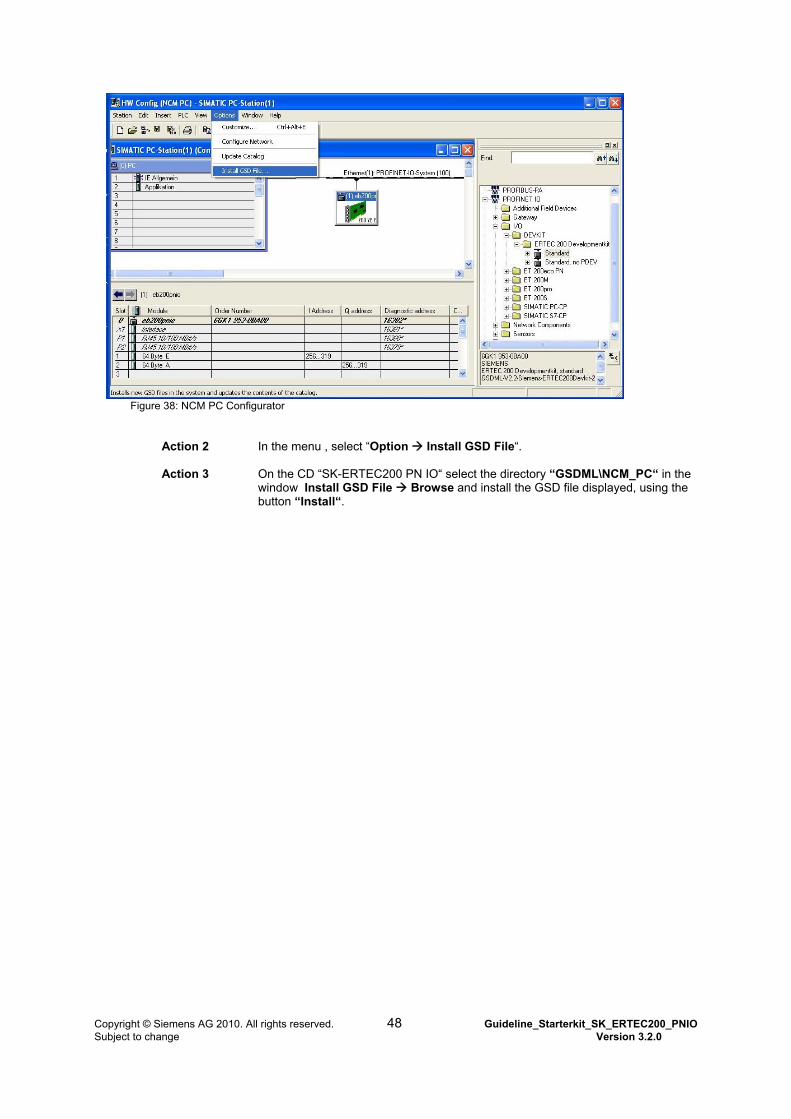
Figure 38: NCM PC Configurator
Action 2 In the menu , select “Option Install GSD File“.
Action 3 On the CD “SK-ERTEC200 PN IO“ select the directory “GSDML\NCM_PC“ in the window Install GSD File Browse and install the GSD file displayed, using the button “Install“.
Copyright © Siemens AG 2010. All rights reserved. 48 Guideline_Starterkit_SK_ERTEC200_PNIO Subject to change Version 3.2.0
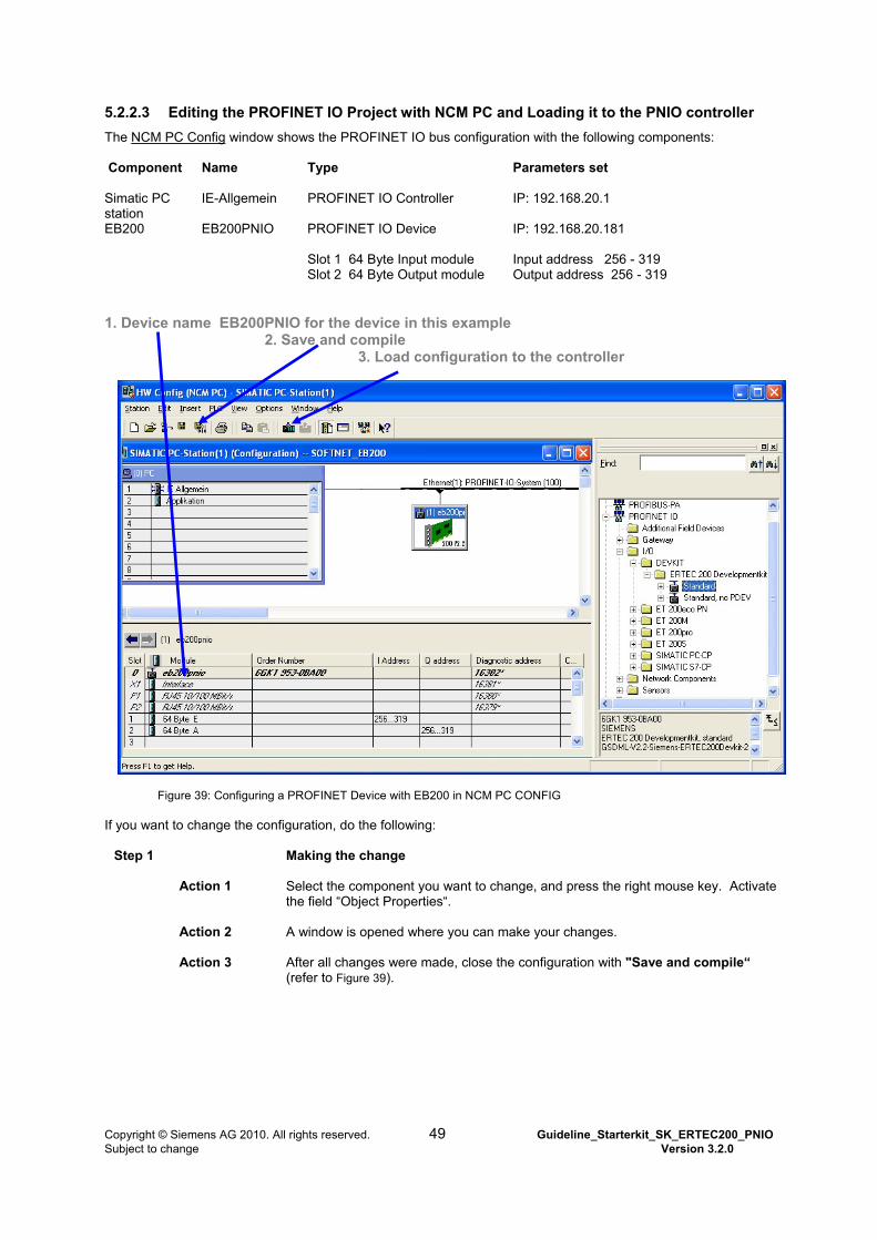
5.2.2.3 Editing the PROFINET IO Project with NCM PC and Loading it to the PNIO controller
The NCM PC Config window shows the PROFINET IO bus configuration with the following components: Component Name Type
Parameters set
Simatic PC station
IE-Allgemein PROFINET IO Controller
IP: 192.168.20.1
EB200 EB200PNIO PROFINET IO Device
IP: 192.168.20.181
Slot 1 64 Byte Input module Slot 2 64 Byte Output module
Input address 256 - 319 Output address 256 - 319
1. Device name EB200PNIO for the device in this example
2. Save and compile 3. Load configuration to the controller
Figure 39: Configuring a PROFINET Device with EB200 in NCM PC CONFIG If you want to change the configuration, do the following:
Step 1 Making the change
Action 1 Select the component you want to change, and press the right mouse key. Activate the field “Object Properties“.
Action 2 A window is opened where you can make your changes.
Action 3 After all changes were made, close the configuration with "Save and compile“ (refer to Figure 39).
Copyright © Siemens AG 2010. All rights reserved. 49 Guideline_Starterkit_SK_ERTEC200_PNIO Subject to change Version 3.2.0
Step 2 Downloading the configuration to the PNIO Controller
Action 1 Connect all components as described in Section 4.7.3 (refer to Figure 17).
Action 2 Load the bus configuration to the PROFINET IO Controller (refer to Figure 39)
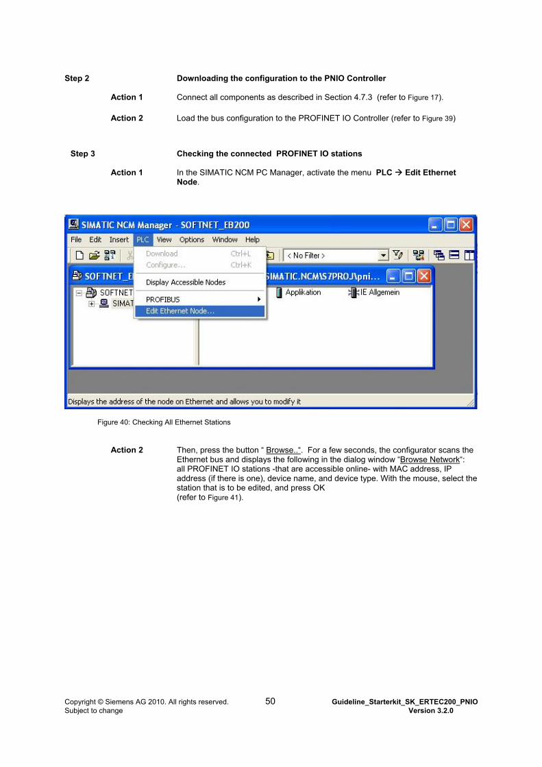
Step 3 Checking the connected PROFINET IO stations
Action 1 In the SIMATIC NCM PC Manager, activate the menu PLC Edit Ethernet
Node.
Figure 40: Checking All Ethernet Stations
Action 2 Then, press the button “ Browse..“. For a few seconds, the configurator scans the Ethernet bus and displays the following in the dialog window “Browse Network“: all PROFINET IO stations -that are accessible online- with MAC address, IP address (if there is one), device name, and device type. With the mouse, select the station that is to be edited, and press OK (refer to Figure 41).
Copyright © Siemens AG 2010. All rights reserved. 50 Guideline_Starterkit_SK_ERTEC200_PNIO Subject to change Version 3.2.0
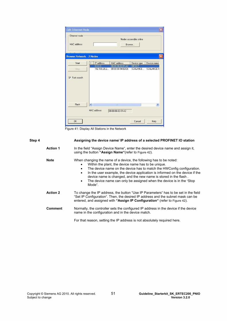
Figure 41: Display All Stations in the Network
Step 4 Assigning the device name/ IP address of a selected PROFINET IO station
Action 1 In the field “Assign Device Name“, enter the desired device name and assign it, using the button “Assign Name“(refer to Figure 42).
Note When changing the name of a device, the following has to be noted: Within the plant, the device name has to be unique. The device name on the device has to match the HWConfig configuration. In the user example, the device application is informed on the device if the
device name is changed, and the new name is stored in the flash . The device name can only be assigned when the device is in the “Stop
Mode“.
Action 2 To change the IP address, the button “Use IP Parameters“ has to be set in the field “Set IP Configuration“. Then, the desired IP address and the subnet mask can be entered, and assigned with “Assign IP Configuration“ (refer to Figure 42).
Comment Normally, the controller sets the configured IP address in the device if the device name in the configuration and in the device match. For that reason, setting the IP address is not absolutely required here.
Copyright © Siemens AG 2010. All rights reserved. 51 Guideline_Starterkit_SK_ERTEC200_PNIO Subject to change Version 3.2.0
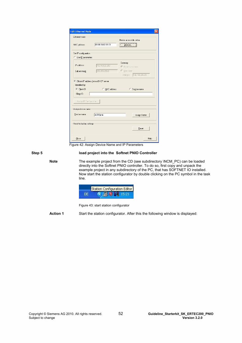
Figure 42: Assign Device Name and IP Parameters
Step 5 load project into the Softnet PNIO Controller
Note The example project from the CD (see subdirectory \NCM_PC) can be loaded
directly into the Softnet PNIO controller. To do so, first copy and unpack the example project in any subdirectory of the PC, that has SOFTNET IO installed. Now start the station configurator by double clicking on the PC symbol in the task line.
Figure 43: start station configurator
Action 1 Start the station configurator. After this the following window is displayed:
Copyright © Siemens AG 2010. All rights reserved. 52 Guideline_Starterkit_SK_ERTEC200_PNIO Subject to change Version 3.2.0
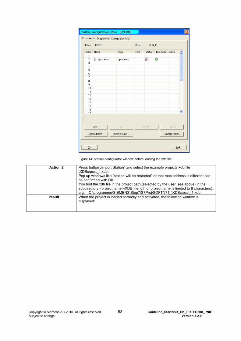
Figure 44: station-configurator window before loading the xdb file
Action 2 Press button „Import Station“ and select the example projects xdb file \XDBs\pcst_1.xdb. Pop up windows like “station will be restarted” or that mac address is different can be confirmed with OK. You find the xdb file in the project path (selected by the user, see above) in the subdirectory <projectname>\XDB (length of projectname is limited to 8 characters), e.g. C:\programme\SIEMENS\Step7\S7Proj\SOFTN71_\XDBs\pcst_1.xdb.
result When the project is loaded correctly and activated, the following window is displayed:
Copyright © Siemens AG 2010. All rights reserved. 53 Guideline_Starterkit_SK_ERTEC200_PNIO Subject to change Version 3.2.0
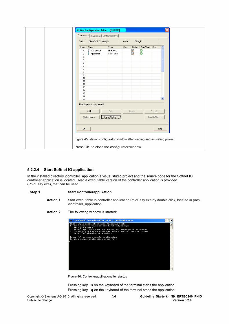
Figure 45: station configurator window after loading and activating project Press OK, to close the configurator window.
5.2.2.4 Start Softnet IO application
In the installed directory \controller_application a visual studio project and the source code for the Softnet IO controller application is located. Also a executable version of the controller application is provided (PnioEasy.exe), that can be used.
Step 1 Start Controllerapplikation
Action 1 Start executable io controller application PnioEasy.exe by double click, located in path \controller_application.
Action 2 The following window is started:
Figure 46: Controllerapplikationafter startup Pressing key s on the keyboard of the terminal starts the application
Pressing key q on the keyboard of the terminal stops the application
Copyright © Siemens AG 2010. All rights reserved. 54 Guideline_Starterkit_SK_ERTEC200_PNIO Subject to change Version 3.2.0
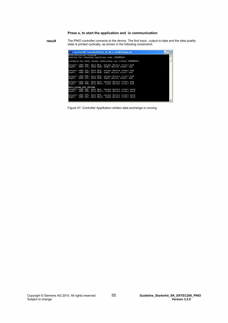
Press s, to start the application and io communication
result The PNIO controller connects to the device. The first input- ,output-io-data and the data quality state is printed cyclically, as shown in the following screenshot.
Figure 47: Controller Applikation whileio data exchange is running
Copyright © Siemens AG 2010. All rights reserved. 55 Guideline_Starterkit_SK_ERTEC200_PNIO Subject to change Version 3.2.0

6 Getting Started with PROFINET IO Device Communication This chapter describes the first steps toward your own device. It is recommended to leave the included device example and the configuration initially unchanged, and starting the first attempts with them. The example was tested on the hardware platform EB200. After you have familiarized yourself with the general PROFINET IO features, you can perform step by step the adaptations for your own device.
Copyright © Siemens AG 2010. All rights reserved. 56 Guideline_Starterkit_SK_ERTEC200_PNIO Subject to change Version 3.2.0
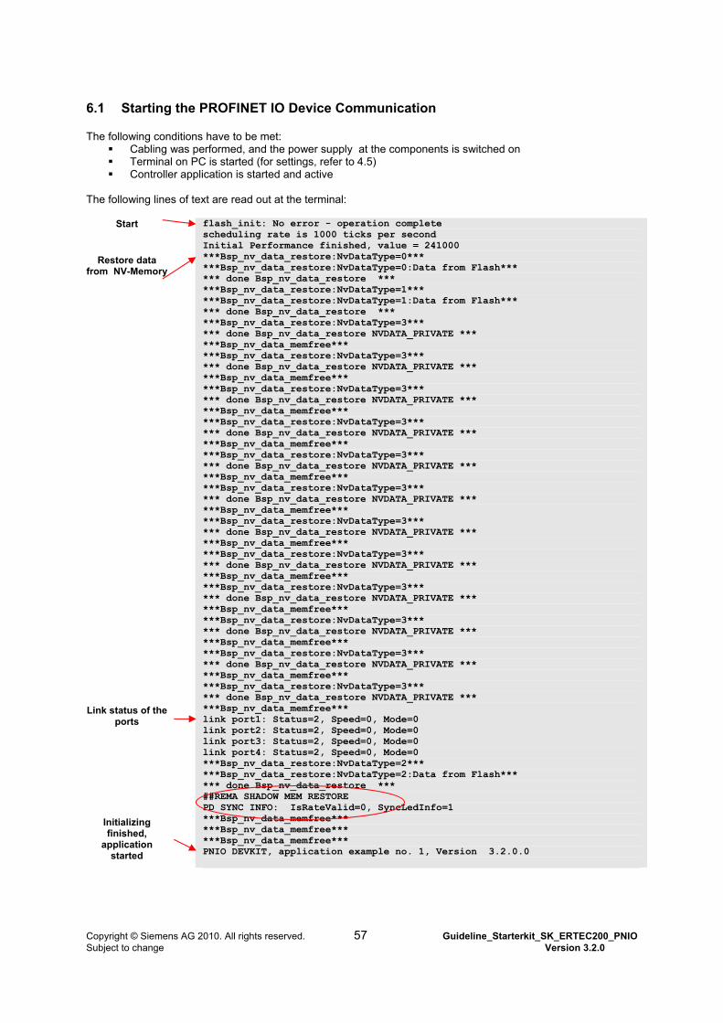
6.1 Starting the PROFINET IO Device Communication
The following conditions have to be met: Cabling was performed, and the power supply at the components is switched on Terminal on PC is started (for settings, refer to 4.5) Controller application is started and active
The following lines of text are read out at the terminal:
Start
Restore data
from NV-Memory
Link status of the ports
Initializing finished,
application started
flash_init: No error - operation complete scheduling rate is 1000 ticks per second Initial Performance finished, value = 241000 ***Bsp_nv_data_restore:NvDataType=0*** ***Bsp_nv_data_restore:NvDataType=0:Data from Flash*** *** done Bsp_nv_data_restore *** ***Bsp_nv_data_restore:NvDataType=1*** ***Bsp_nv_data_restore:NvDataType=1:Data from Flash*** *** done Bsp_nv_data_restore *** ***Bsp_nv_data_restore:NvDataType=3*** *** done Bsp_nv_data_restore NVDATA_PRIVATE *** ***Bsp_nv_data_memfree*** ***Bsp_nv_data_restore:NvDataType=3*** *** done Bsp_nv_data_restore NVDATA_PRIVATE *** ***Bsp_nv_data_memfree*** ***Bsp_nv_data_restore:NvDataType=3*** *** done Bsp_nv_data_restore NVDATA_PRIVATE *** ***Bsp_nv_data_memfree*** ***Bsp_nv_data_restore:NvDataType=3*** *** done Bsp_nv_data_restore NVDATA_PRIVATE *** ***Bsp_nv_data_memfree*** ***Bsp_nv_data_restore:NvDataType=3*** *** done Bsp_nv_data_restore NVDATA_PRIVATE *** ***Bsp_nv_data_memfree*** ***Bsp_nv_data_restore:NvDataType=3*** *** done Bsp_nv_data_restore NVDATA_PRIVATE *** ***Bsp_nv_data_memfree*** ***Bsp_nv_data_restore:NvDataType=3*** *** done Bsp_nv_data_restore NVDATA_PRIVATE *** ***Bsp_nv_data_memfree*** ***Bsp_nv_data_restore:NvDataType=3*** *** done Bsp_nv_data_restore NVDATA_PRIVATE *** ***Bsp_nv_data_memfree*** ***Bsp_nv_data_restore:NvDataType=3*** *** done Bsp_nv_data_restore NVDATA_PRIVATE *** ***Bsp_nv_data_memfree*** ***Bsp_nv_data_restore:NvDataType=3*** *** done Bsp_nv_data_restore NVDATA_PRIVATE *** ***Bsp_nv_data_memfree*** ***Bsp_nv_data_restore:NvDataType=3*** *** done Bsp_nv_data_restore NVDATA_PRIVATE *** ***Bsp_nv_data_memfree*** ***Bsp_nv_data_restore:NvDataType=3*** *** done Bsp_nv_data_restore NVDATA_PRIVATE *** ***Bsp_nv_data_memfree*** link port1: Status=2, Speed=0, Mode=0 link port2: Status=2, Speed=0, Mode=0 link port3: Status=2, Speed=0, Mode=0 link port4: Status=2, Speed=0, Mode=0 ***Bsp_nv_data_restore:NvDataType=2*** ***Bsp_nv_data_restore:NvDataType=2:Data from Flash*** *** done Bsp_nv_data_restore *** ##REMA SHADOW MEM RESTORE PD SYNC INFO: IsRateValid=0, SyncLedInfo=1 ***Bsp_nv_data_memfree*** ***Bsp_nv_data_memfree*** ***Bsp_nv_data_memfree*** PNIO DEVKIT, application example no. 1, Version 3.2.0.0
Copyright © Siemens AG 2010. All rights reserved. 57 Guideline_Starterkit_SK_ERTEC200_PNIO Subject to change Version 3.2.0
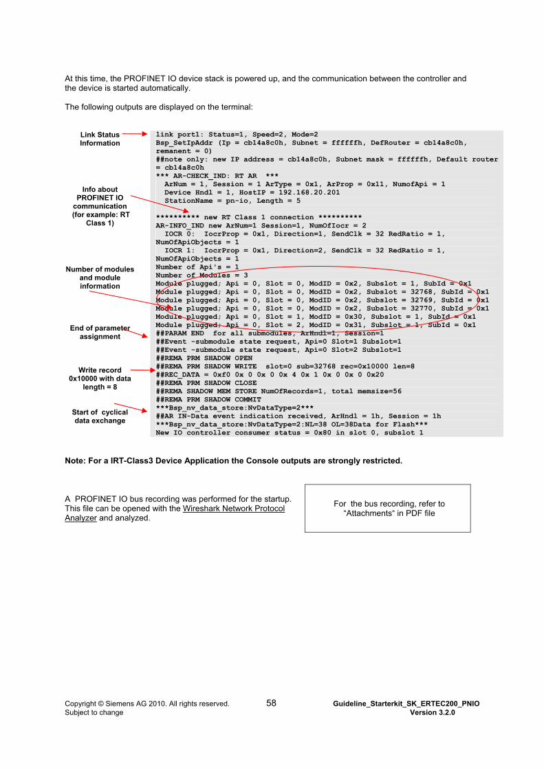
At this time, the PROFINET IO device stack is powered up, and the communication between the controller and the device is started automatically. The following outputs are displayed on the terminal:
Link Status Information
Info about PROFINET IO
communication (for example: RT
Class 1)
Number of modules and module information
End of parameter assignment
Write record 0x10000 with data
length = 8
Start of cyclical data exchange
link port1: Status=1, Speed=2, Mode=2 Bsp_SetIpAddr (Ip = cb14a8c0h, Subnet = ffffffh, DefRouter = cb14a8c0h, remanent = 0) ##note only: new IP address = cb14a8c0h, Subnet mask = ffffffh, Default router = cb14a8c0h *** AR-CHECK_IND: RT AR *** ArNum = 1, Session = 1 ArType = 0x1, ArProp = 0x11, NumofApi = 1 Device Hndl = 1, HostIP = 192.168.20.201 StationName = pn-io, Length = 5 ********** new RT Class 1 connection ********** AR-INFO_IND new ArNum=1 Session=1, NumOfIocr = 2 IOCR 0: IocrProp = 0x1, Direction=1, SendClk = 32 RedRatio = 1, NumOfApiObjects = 1 IOCR 1: IocrProp = 0x1, Direction=2, SendClk = 32 RedRatio = 1, NumOfApiObjects = 1 Number of Api's = 1 Number of Modules = 3 Module plugged; Api = 0, Slot = 0, ModID = 0x2, Subslot = 1, SubId = 0x1 Module plugged; Api = 0, Slot = 0, ModID = 0x2, Subslot = 32768, SubId = 0x1 Module plugged; Api = 0, Slot = 0, ModID = 0x2, Subslot = 32769, SubId = 0x1 Module plugged; Api = 0, Slot = 0, ModID = 0x2, Subslot = 32770, SubId = 0x1 Module plugged; Api = 0, Slot = 1, ModID = 0x30, Subslot = 1, SubId = 0x1 Module plugged; Api = 0, Slot = 2, ModID = 0x31, Subslot = 1, SubId = 0x1 ##PARAM END for all submodules, ArHndl=1, Session=1 ##Event -submodule state request, Api=0 Slot=1 Subslot=1 ##Event -submodule state request, Api=0 Slot=2 Subslot=1 ##REMA PRM SHADOW OPEN ##REMA PRM SHADOW WRITE slot=0 sub=32768 rec=0x10000 len=8 ##REC_DATA = 0xf0 0x 0 0x 0 0x 4 0x 1 0x 0 0x 0 0x20 ##REMA PRM SHADOW CLOSE ##REMA SHADOW MEM STORE NumOfRecords=1, total memsize=56 ##REMA PRM SHADOW COMMIT ***Bsp_nv_data_store:NvDataType=2*** ##AR IN-Data event indication received, ArHndl = 1h, Session = 1h ***Bsp_nv_data_store:NvDataType=2:NL=38 OL=38Data for Flash*** New IO controller consumer status = 0x80 in slot 0, subslot 1
Note: For a IRT-Class3 Device Application the Console outputs are strongly restricted. A PROFINET IO bus recording was performed for the startup. This file can be opened with the Wireshark Network Protocol Analyzer and analyzed.
For the bus recording, refer to “Attachments“ in PDF file
Copyright © Siemens AG 2010. All rights reserved. 58 Guideline_Starterkit_SK_ERTEC200_PNIO Subject to change Version 3.2.0
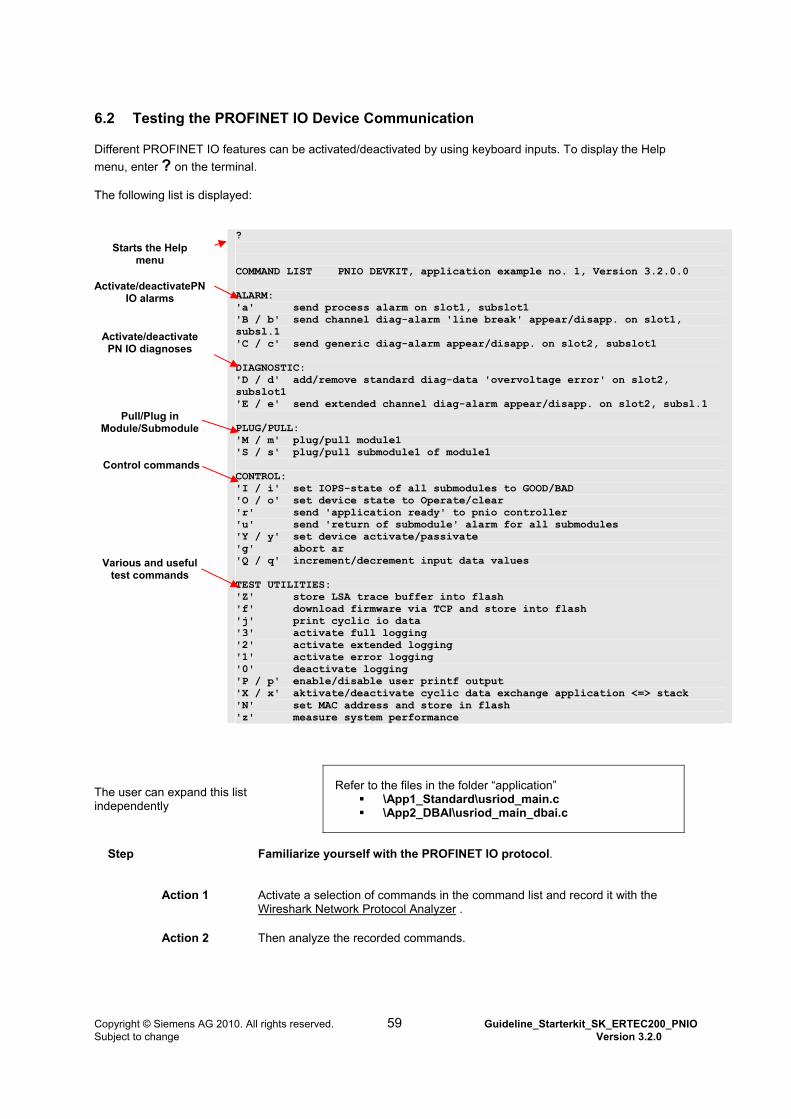
6.2 Testing the PROFINET IO Device Communication
Different PROFINET IO features can be activated/deactivated by using keyboard inputs. To display the Help
menu, enter ? on the terminal. The following list is displayed:
Starts the Help
menu
Activate/deactivatePN IO alarms
Activate/deactivate PN IO diagnoses
Pull/Plug in Module/Submodule
Control commands
Various and useful test commands
? COMMAND LIST PNIO DEVKIT, application example no. 1, Version 3.2.0.0 ALARM: 'a' send process alarm on slot1, subslot1 'B / b' send channel diag-alarm 'line break' appear/disapp. on slot1, subsl.1 'C / c' send generic diag-alarm appear/disapp. on slot2, subslot1 DIAGNOSTIC: 'D / d' add/remove standard diag-data 'overvoltage error' on slot2, subslot1 'E / e' send extended channel diag-alarm appear/disapp. on slot2, subsl.1 PLUG/PULL: 'M / m' plug/pull module1 'S / s' plug/pull submodule1 of module1 CONTROL: 'I / i' set IOPS-state of all submodules to GOOD/BAD 'O / o' set device state to Operate/clear 'r' send 'application ready' to pnio controller 'u' send 'return of submodule' alarm for all submodules 'Y / y' set device activate/passivate 'g' abort ar 'Q / q' increment/decrement input data values TEST UTILITIES: 'Z' store LSA trace buffer into flash 'f' download firmware via TCP and store into flash 'j' print cyclic io data '3' activate full logging '2' activate extended logging '1' activate error logging '0' deactivate logging 'P / p' enable/disable user printf output 'X / x' aktivate/deactivate cyclic data exchange application <=> stack 'N' set MAC address and store in flash 'z' measure system performance
The user can expand this list independently
Refer to the files in the folder “application” \App1_Standard\usriod_main.c \App2_DBAI\usriod_main_dbai.c
Step Familiarize yourself with the PROFINET IO protocol.
Action 1 Activate a selection of commands in the command list and record it with the Wireshark Network Protocol Analyzer .
Action 2 Then analyze the recorded commands.
Copyright © Siemens AG 2010. All rights reserved. 59 Guideline_Starterkit_SK_ERTEC200_PNIO Subject to change Version 3.2.0

Copyright © Siemens AG 2010. All rights reserved. 60 Guideline_Starterkit_SK_ERTEC200_PNIO Subject to change Version 3.2.0
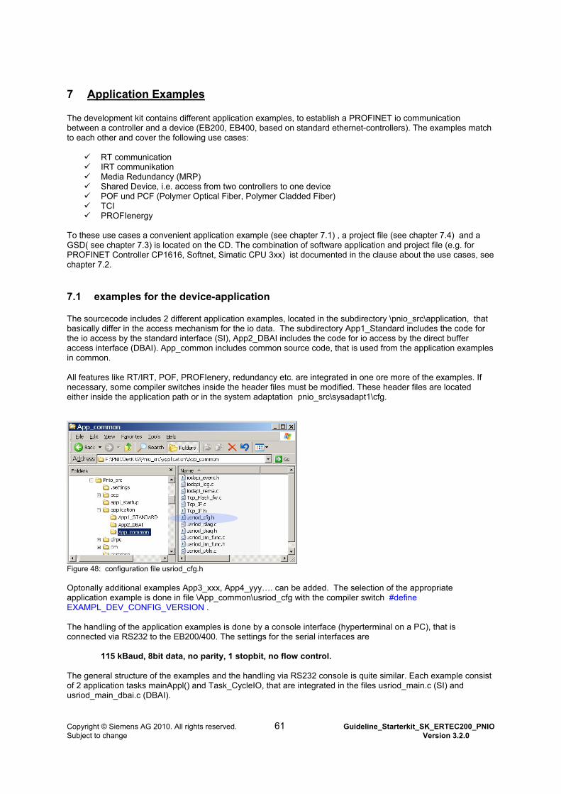
7 Application Examples The development kit contains different application examples, to establish a PROFINET io communication between a controller and a device (EB200, EB400, based on standard ethernet-controllers). The examples match to each other and cover the following use cases:
RT communication IRT communikation Media Redundancy (MRP) Shared Device, i.e. access from two controllers to one device POF und PCF (Polymer Optical Fiber, Polymer Cladded Fiber) TCI PROFIenergy
To these use cases a convenient application example (see chapter 7.1) , a project file (see chapter 7.4) and a GSD( see chapter 7.3) is located on the CD. The combination of software application and project file (e.g. for PROFINET Controller CP1616, Softnet, Simatic CPU 3xx) ist documented in the clause about the use cases, see chapter 7.2.
7.1 examples for the device-application
The sourcecode includes 2 different application examples, located in the subdirectory \pnio_src\application, that basically differ in the access mechanism for the io data. The subdirectory App1_Standard includes the code for the io access by the standard interface (SI), App2_DBAI includes the code for io access by the direct buffer access interface (DBAI). App_common includes common source code, that is used from the application examples in common. All features like RT/IRT, POF, PROFIenery, redundancy etc. are integrated in one ore more of the examples. If necessary, some compiler switches inside the header files must be modified. These header files are located either inside the application path or in the system adaptation pnio_src\sysadapt1\cfg.
Figure 48: configuration file usriod_cfg.h Optonally additional examples App3_xxx, App4_yyy…. can be added. The selection of the appropriate application example is done in file \App_common\usriod_cfg with the compiler switch #define EXAMPL_DEV_CONFIG_VERSION . The handling of the application examples is done by a console interface (hyperterminal on a PC), that is connected via RS232 to the EB200/400. The settings for the serial interfaces are
115 kBaud, 8bit data, no parity, 1 stopbit, no flow control. The general structure of the examples and the handling via RS232 console is quite similar. Each example consist of 2 application tasks mainAppl() and Task_CycleIO, that are integrated in the files usriod_main.c (SI) and usriod_main_dbai.c (DBAI).
Copyright © Siemens AG 2010. All rights reserved. 61 Guideline_Starterkit_SK_ERTEC200_PNIO Subject to change Version 3.2.0
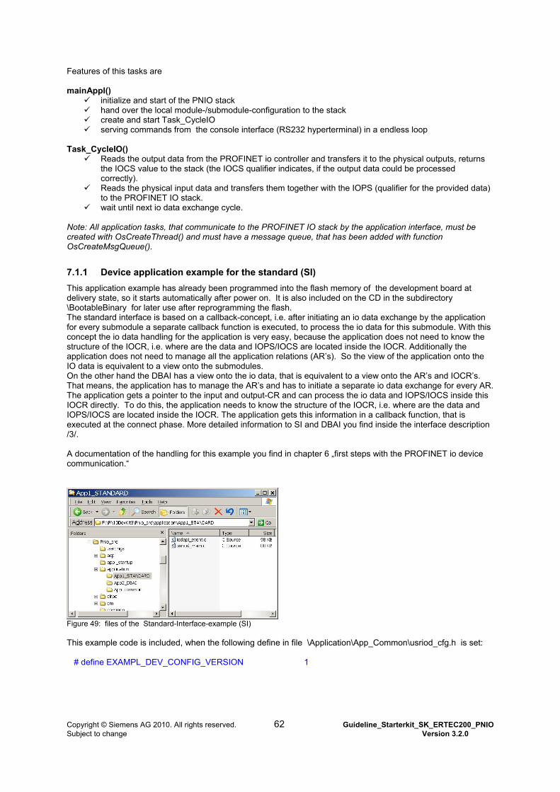
Features of this tasks are mainAppl()
initialize and start of the PNIO stack hand over the local module-/submodule-configuration to the stack create and start Task_CycleIO serving commands from the console interface (RS232 hyperterminal) in a endless loop
Task_CycleIO()
Reads the output data from the PROFINET io controller and transfers it to the physical outputs, returns the IOCS value to the stack (the IOCS qualifier indicates, if the output data could be processed correctly).
Reads the physical input data and transfers them together with the IOPS (qualifier for the provided data) to the PROFINET IO stack.
wait until next io data exchange cycle. Note: All application tasks, that communicate to the PROFINET IO stack by the application interface, must be created with OsCreateThread() and must have a message queue, that has been added with function OsCreateMsgQueue().
7.1.1 Device application example for the standard (SI)
This application example has already been programmed into the flash memory of the development board at delivery state, so it starts automatically after power on. It is also included on the CD in the subdirectory \BootableBinary for later use after reprogramming the flash. The standard interface is based on a callback-concept, i.e. after initiating an io data exchange by the application for every submodule a separate callback function is executed, to process the io data for this submodule. With this concept the io data handling for the application is very easy, because the application does not need to know the structure of the IOCR, i.e. where are the data and IOPS/IOCS are located inside the IOCR. Additionally the application does not need to manage all the application relations (AR’s). So the view of the application onto the IO data is equivalent to a view onto the submodules. On the other hand the DBAI has a view onto the io data, that is equivalent to a view onto the AR’s and IOCR’s. That means, the application has to manage the AR’s and has to initiate a separate io data exchange for every AR. The application gets a pointer to the input and output-CR and can process the io data and IOPS/IOCS inside this IOCR directly. To do this, the application needs to know the structure of the IOCR, i.e. where are the data and IOPS/IOCS are located inside the IOCR. The application gets this information in a callback function, that is executed at the connect phase. More detailed information to SI and DBAI you find inside the interface description /3/. A documentation of the handling for this example you find in chapter 6 „first steps with the PROFINET io device communication.“
Figure 49: files of the Standard-Interface-example (SI) This example code is included, when the following define in file \Application\App_Common\usriod_cfg.h is set: # define EXAMPL_DEV_CONFIG_VERSION 1
Copyright © Siemens AG 2010. All rights reserved. 62 Guideline_Starterkit_SK_ERTEC200_PNIO Subject to change Version 3.2.0
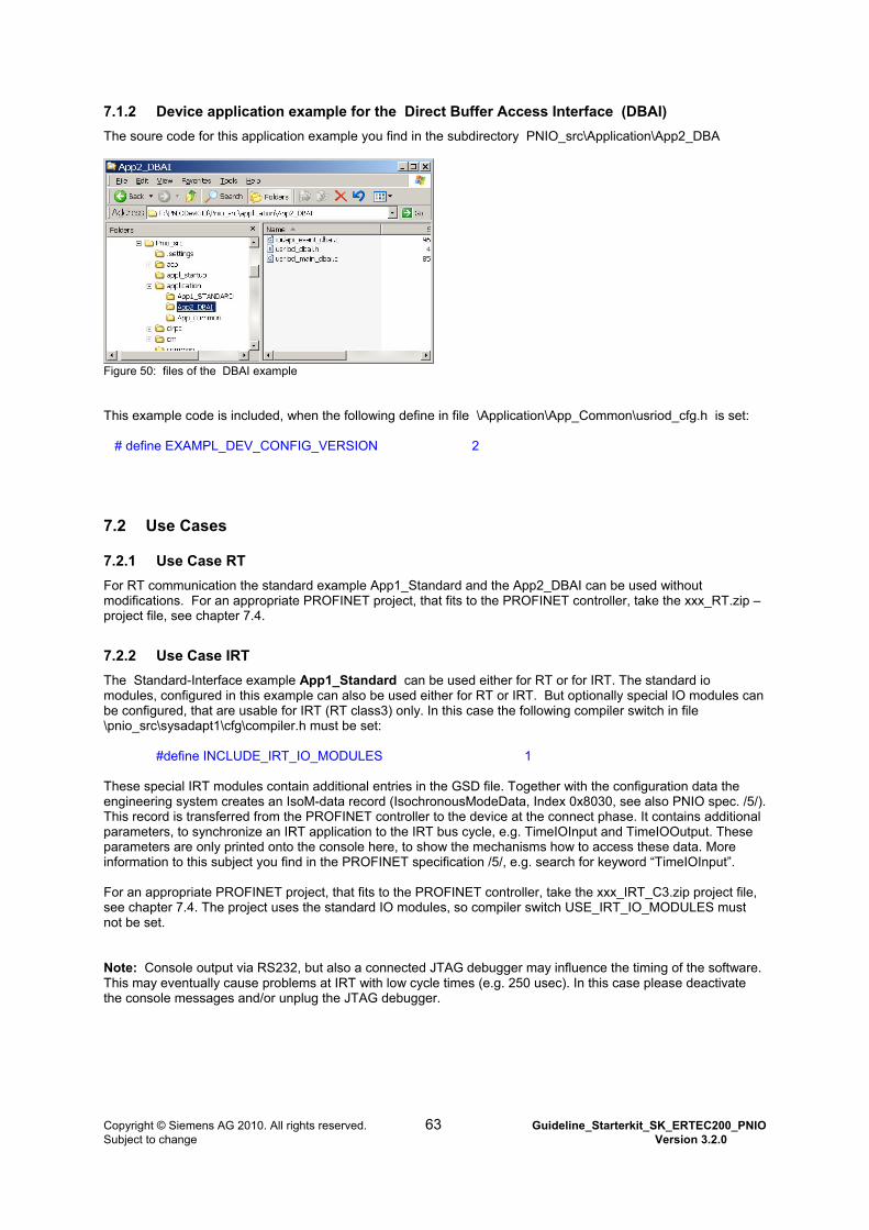
7.1.2 Device application example for the Direct Buffer Access Interface (DBAI)
The soure code for this application example you find in the subdirectory PNIO_src\Application\App2_DBA
Figure 50: files of the DBAI example This example code is included, when the following define in file \Application\App_Common\usriod_cfg.h is set: # define EXAMPL_DEV_CONFIG_VERSION 2
7.2 Use Cases
7.2.1 Use Case RT
For RT communication the standard example App1_Standard and the App2_DBAI can be used without modifications. For an appropriate PROFINET project, that fits to the PROFINET controller, take the xxx_RT.zip –project file, see chapter 7.4.
7.2.2 Use Case IRT
The Standard-Interface example App1_Standard can be used either for RT or for IRT. The standard io modules, configured in this example can also be used either for RT or IRT. But optionally special IO modules can be configured, that are usable for IRT (RT class3) only. In this case the following compiler switch in file \pnio_src\sysadapt1\cfg\compiler.h must be set: #define INCLUDE_IRT_IO_MODULES 1 These special IRT modules contain additional entries in the GSD file. Together with the configuration data the engineering system creates an IsoM-data record (IsochronousModeData, Index 0x8030, see also PNIO spec. /5/). This record is transferred from the PROFINET controller to the device at the connect phase. It contains additional parameters, to synchronize an IRT application to the IRT bus cycle, e.g. TimeIOInput and TimeIOOutput. These parameters are only printed onto the console here, to show the mechanisms how to access these data. More information to this subject you find in the PROFINET specification /5/, e.g. search for keyword “TimeIOInput”. For an appropriate PROFINET project, that fits to the PROFINET controller, take the xxx_IRT_C3.zip project file, see chapter 7.4. The project uses the standard IO modules, so compiler switch USE_IRT_IO_MODULES must not be set. Note: Console output via RS232, but also a connected JTAG debugger may influence the timing of the software. This may eventually cause problems at IRT with low cycle times (e.g. 250 usec). In this case please deactivate the console messages and/or unplug the JTAG debugger.
Copyright © Siemens AG 2010. All rights reserved. 63 Guideline_Starterkit_SK_ERTEC200_PNIO Subject to change Version 3.2.0
7.2.3 Use Case fiberoptic transceiver AVAGO QFBR-5978
This application example is also integrated into App1_Standard (SI Standard-interface) . see chapter 7.1. To use POF with the transceivers described above , the following define in file \sysadapt1\cfg\compiler.h must be set: #define INCLUDE_POF 1 This version supports POF- and PCF-cables. A ready to use example, modified for POF, including GSD file, STEP7 project (for a CPU319) and application is on the CD. It can be used without modification on an EB200, that has been assembled for POF transceivers (AVAGO QFBR-5978). For POF diagnostic via the I2C interface the following 4 GPIOs are used: GPIO 15 SCL Port 1 GPIO 13 SDA Port 1 GPIO 3 SCL Port 2 GPIO 2 SDA Port 2 The necessary hardware modifications on the EB200 are described in the document EB200_ModificationInstructions_POF_en.pdf. Included as an attachment to this pdf file are also the EB200 assembly drawings (top and bottom) and the EB200 circuit diagram with POF. If other GPIOs shall be used, they must be adapted in file \Pnio_Src\sysadapt1\cfg\ertec_cfg.h. But it is recommended, to take them as they are (if possible). Additionally for use of POF the control of the read and green LED must be deactivated, because the corresponding GPIOs are used for POF now. This affects the functions Bsp_Init() and Bsp_EbSetLed(). For an appropriate PROFINET project, that fits to the PROFINET controller, take the xxx_POF.zip project file, see chapter 7.4. Purchase of the transceiver AVAGO QFBR for POF-support In the SK-ERTEC 200 PN IO and DK-ERTEC 200/400 PN IO a firmware package for PROFINET communication with POF is integrated. To use this package, the POF transceiver AVAGO QFBR-5978 is necessary. To get more information about purchase conditions for this chip, please contact ComDeC: [email protected].
7.2.4 Use Case Tool Calling Interface (TCI)
Controller-Application and CPD Tool A ready to use application example for TCI you find on the development kit CD in the subdirectory \tools\TCI. It includes an example CDP tool, that uses the STEP7 communication server, to connect to the PROFINET IO device EB200/EB400. It writes/reads and 4 byte example record (record-index 50). The content of this 4 byte record can be modified in the user window of the the CPD tool. The CPD tool example has been created with Microsoft Visual Studio V6, an appropriate project file S7TCITest.dsp and the sourcecode of the CPD tool is located in the subdirectory \tools\TCI\CpdTool\MSVC. A user documentation for the CPD tool you find on the CD in subdirectory tools\TCI\CpdTool\doc. On the PC with the CPD tool additionally STEP7 (including the communication server) must be installed and started. The CPD tool example only can be executed from STEP7. Device-Application TCI is included in the standard application example App1_STANDARD, i.e. this must be loaded and started on the device first. The TCI example works as follows: When a record request on index 50 is received, an example record with length 4 byte is stored in the application ram and can be read back with a record read request on the same index. At every read- or write access to this record a message is printed on the console. Note : To start the CPD tool and use the communication server for accessing the device, Step7 version5.4 SP4 or newer is necessary. In NCM/PC no communication server is included.
Copyright © Siemens AG 2010. All rights reserved. 64 Guideline_Starterkit_SK_ERTEC200_PNIO Subject to change Version 3.2.0
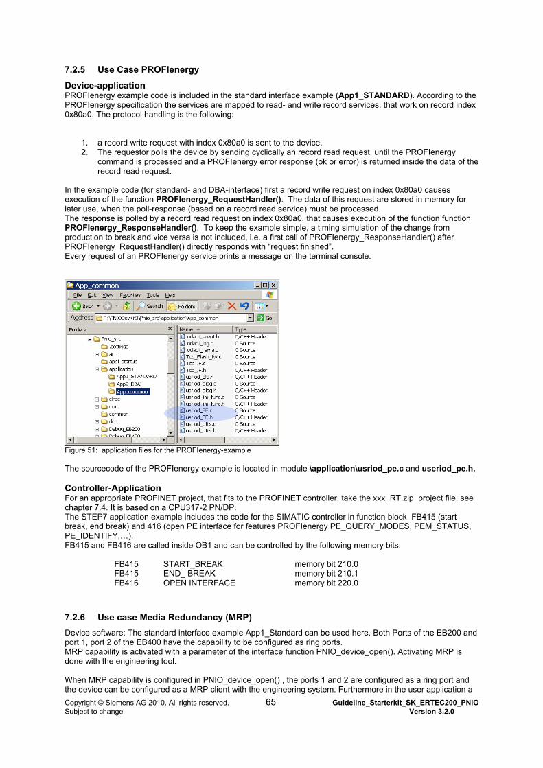
7.2.5 Use Case PROFIenergy
Device-application PROFIenergy example code is included in the standard interface example (App1_STANDARD). According to the PROFIenergy specification the services are mapped to read- and write record services, that work on record index 0x80a0. The protocol handling is the following:
1. a record write request with index 0x80a0 is sent to the device. 2. The requestor polls the device by sending cyclically an record read request, until the PROFIenergy
command is processed and a PROFIenergy error response (ok or error) is returned inside the data of the record read request.
In the example code (for standard- and DBA-interface) first a record write request on index 0x80a0 causes execution of the function PROFIenergy_RequestHandler(). The data of this request are stored in memory for later use, when the poll-response (based on a record read service) must be processed. The response is polled by a record read request on index 0x80a0, that causes execution of the function function PROFIenergy_ResponseHandler(). To keep the example simple, a timing simulation of the change from production to break and vice versa is not included, i.e. a first call of PROFIenergy_ResponseHandler() after PROFIenergy_RequestHandler() directly responds with “request finished”. Every request of an PROFIenergy service prints a message on the terminal console.
Figure 51: application files for the PROFIenergy-example The sourcecode of the PROFIenergy example is located in module \application\usriod_pe.c and useriod_pe.h, Controller-Application For an appropriate PROFINET project, that fits to the PROFINET controller, take the xxx_RT.zip project file, see chapter 7.4. It is based on a CPU317-2 PN/DP. The STEP7 application example includes the code for the SIMATIC controller in function block FB415 (start break, end break) and 416 (open PE interface for features PROFIenergy PE_QUERY_MODES, PEM_STATUS, PE_IDENTIFY,…). FB415 and FB416 are called inside OB1 and can be controlled by the following memory bits: FB415 START_BREAK memory bit 210.0 FB415 END_ BREAK memory bit 210.1 FB416 OPEN INTERFACE memory bit 220.0
7.2.6 Use case Media Redundancy (MRP)
Device software: The standard interface example App1_Standard can be used here. Both Ports of the EB200 and port 1, port 2 of the EB400 have the capability to be configured as ring ports. MRP capability is activated with a parameter of the interface function PNIO_device_open(). Activating MRP is done with the engineering tool. When MRP capability is configured in PNIO_device_open() , the ports 1 and 2 are configured as a ring port and the device can be configured as a MRP client with the engineering system. Furthermore in the user application a
Copyright © Siemens AG 2010. All rights reserved. 65 Guideline_Starterkit_SK_ERTEC200_PNIO Subject to change Version 3.2.0
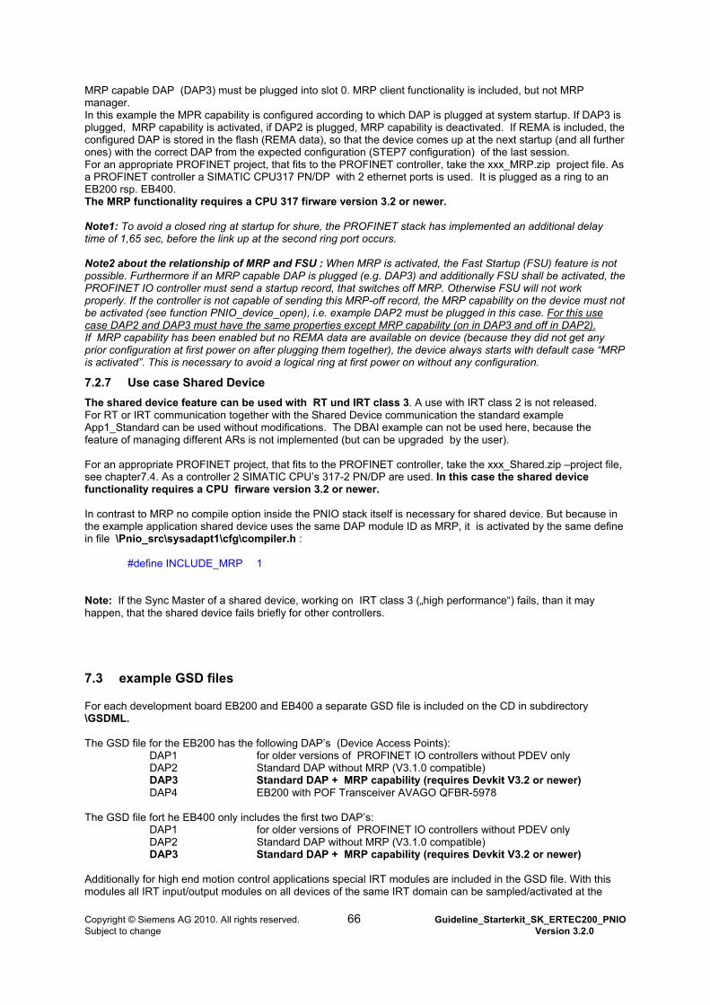
MRP capable DAP (DAP3) must be plugged into slot 0. MRP client functionality is included, but not MRP manager. In this example the MPR capability is configured according to which DAP is plugged at system startup. If Dplugged, M
AP3 is RP capability is activated, if DAP2 is plugged, MRP capability is deactivated. If REMA is included, the
g to an
plemented an additional delay me of 1,65 sec, before the link up at the second ring port occurs.
tivated, the Fast Startup (FSU) feature is not ossible. Furthermore if an MRP capable DAP is plugged (e.g. DAP3) and additionally FSU shall be activated, the
se
configured DAP is stored in the flash (REMA data), so that the device comes up at the next startup (and all further ones) with the correct DAP from the expected configuration (STEP7 configuration) of the last session. For an appropriate PROFINET project, that fits to the PROFINET controller, take the xxx_MRP.zip project file. As a PROFINET controller a SIMATIC CPU317 PN/DP with 2 ethernet ports is used. It is plugged as a rinEB200 rsp. EB400. The MRP functionality requires a CPU 317 firware version 3.2 or newer. Note1: To avoid a closed ring at startup for shure, the PROFINET stack has imti Note2 about the relationship of MRP and FSU : When MRP is acpPROFINET IO controller must send a startup record, that switches off MRP. Otherwise FSU will not work properly. If the controller is not capable of sending this MRP-off record, the MRP capability on the device must not be activated (see function PNIO_device_open), i.e. example DAP2 must be plugged in this case. For this ucase DAP2 and DAP3 must have the same properties except MRP capability (on in DAP3 and off in DAP2). If MRP capability has been enabled but no REMA data are available on device (because they did not get any prior configuration at first power on after plugging them together), the device always starts with default case “MRP
ed with RT und IRT class 3. A use with IRT class 2 is not released. with the Shared Device communication the standard example
hared.zip –project file, e chapter7.4. As a controller 2 SIMATIC CPU’s 317-2 PN/DP are used. In this case the shared device
lf is necessary for shared device. But because in e example application shared device uses the same DAP module ID as MRP, it is activated by the same define
ote: If the Sync Master of a shared device, working on IRT class 3 („high performance“) fails, than it may appen, that the shared device fails briefly for other controllers.
.3 example GSD files
200 and EB400 a separate GSD file is included on the CD in subdirectory \GSDML.
e for the EB200 has the following DAP’s (Device Access Points): DAP1 for older versions of PROFINET IO controllers without PDEV only
atible)
he GSD file fort he EB40 nly inclDAP1 for older versions of PROFINET IO controllers without PDEV only
P (V3.1.0 compatible)
dditionally fo nd motion con this odules all IRT input/output modules on all devices of the same IRT domain can be sampled/activated at the
is activated”. This is necessary to avoid a logical ring at first power on without any configuration.
7.2.7 Use case Shared Device
The shared device feature can be usFor RT or IRT communication together App1_Standard can be used without modifications. The DBAI example can not be used here, because the feature of managing different ARs is not implemented (but can be upgraded by the user). For an appropriate PROFINET project, that fits to the PROFINET controller, take the xxx_Ssefunctionality requires a CPU firware version 3.2 or newer. In contrast to MRP no compile option inside the PNIO stack itsethin file \Pnio_src\sysadapt1\cfg\compiler.h : #define INCLUDE_MRP 1 Nh
7
For each development board EB
The GSD fil DAP2 Standard DAP without MRP (V3.1.0 comp DAP3 Standard DAP + MRP capability (requires Devkit V3.2 or newer) DAP4 EB200 with POF Transceiver AVAGO QFBR-5978 T 0 o udes the first two DAP’s: DAP2 Standard DAP without MR DAP3 Standard DAP + MRP capability (requires Devkit V3.2 or newer) A r high e trol applications special IRT modules are included in the GSD file. Withm
Copyright © Siemens AG 2010. All rights reserved. 66 Guideline_Starterkit_SK_ERTEC200_PNIO Subject to change Version 3.2.0
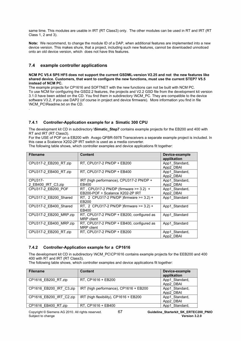
same time. This modules are usable in IRT (RT Class3) only. The other modules can be used in RT and IRT (RClass 1, 2 and 3). Note: We recomm
T
end, to change the module ID of a DAP, when additional features are implemented into a new evice version. This makes shure, that a project, including such new features, cannot be downloaded unnoticed
.4 example controller applications
rrent GSDML-version V2.25 and not the new features like shared device. Customers, that want to configure the new functions, must use the current STEP7 V5.5
uring the GSD2.2 features, the projects and V2.2 GSD file from the development kit version evice
.4.1 Controller-Application example for a Simatic 300 CPU
and 400 with
n IRT switch is used as a media converter.
donto an old device version, which does not have this features.
7
NCM PC V5.4 SP5 HF5 does not support the cu
instead of NCM PC. The example projects for CP1616 and SOFTNET with the new functions can not be built with NCM PC. To use NCM for config3.1.0 have been added on the CD. You find them in subdirectory \NCM_PC. They are compatible to the dsoftware V3.2, if you use DAP2 (of course in project and device firmware). More information you find in file \NCM_PC\Readme.txt on the CD. .
7
The development kit CD in subdirectory \Simatic_Step7 contains example projects for the EB200 RT and IRT (RT Class3). For the USE of POF on a EB200 with Avago QFBR-5978 Transceivers a separate example project is included. Ithis case a Scalance X202-2PThe following table shows, which controller examples and device applications fit together: Filename Content Device-example
applikation CPU317-2_EB200_RT.zip 17-2 PN/DP + EB200 RT, CPU3 App1_Standard,
App2_DBAI CPU317-2_EB400_RT.zip RT, CPU317-2 PN/DP + EB400 App1_Standard,
App2_DBAI CPU317-2_EB400_IRT_C3.zip
-2 PN/DP + EB400 IRT (high performance), CPU317 App1_Standard,
App2_DBAI CPU317-2_EB200_POF
OF + Scalance X202-2P IRT RT , CPU317-2 PN/DP (firmware >= 3.2) + EB200-P
App1_Standard, App2_DBAI
CPU317-2_EB200_Shared RT, 2 CPU317-2 PN/DP )firmware >= 3.2) +EB200
App1_Standard
CPU317-2_EB400_Shared RT, 2 CPU317-2 PN/DP )firmware >= 3.2) + EB400
App1_Standard
CPU317-2_EB200_MRP.zip nt
RT, CPU317-2 PN/DP + EB200, configured asMRP clie
App1_Standard
CPU317-2_EB400_MRP.zip RT, CPU317-2 PN/DP + EB400, configured as MRP client
App1_Standard
CPU317-2_EB200_RT.zip RT, CPU317-2 PN/DP + EB200 App1_Standard, App2_DBAI
7.4.2 Controller-Application example for a CP1616
ins example projects for the EEB200 and 400 The development kit CD in subdirectory \NCM_PC\CP1616 conta400 with RT and IRT (RT Class3). The following table shows, which controller examples and device applications fit together: Filename Content Device-example
applikation CP1616_EB200_RT.zip 16 + EB200 RT, CP16 App1_Standard,
App2_DBAI CP1616_EB200_IRT_C3.zip , CP1616 + EB200 IRT (high performance) App1_Standard,
App2_DBAI CP1616_EB200_IRT_C2.zip IRT (high flexibility), CP1616 + EB200 App1_Standard,
App2_DBAI CP1616_EB400_RT.zip RT, CP1616 + EB400 App1_Standard,
Copyright © Siemens AG 2010. All rights reserved. 67 Guideline_Starterkit_SK_ERTEC200_PNIO Subject to change Version 3.2.0
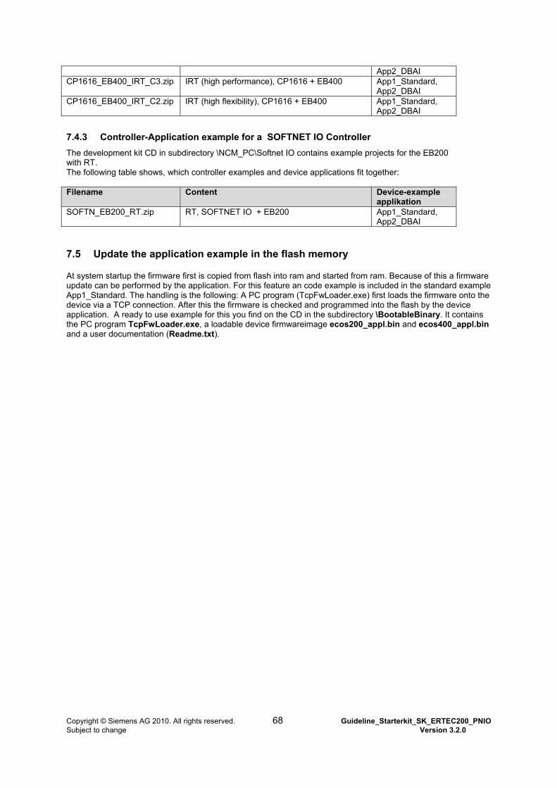
App2_DBAI CP1616_EB400_IRT_C3.zip , CP1616 + EB400 IRT (high performance) App1_Standard,
App2_DBAI CP1616_EB400_IRT_C2.zip IRT (high flexibility), CP1616 + EB400 App1_Standard,
App2_DBAI
7.4.3 Controller-Application example for a SOFTNET IO Controller
0 The development kit CD in subdirectory \NCM_PC\Softnet IO contains example projects for the EB20with RT. The following table shows, which controller examples and device applications fit together: Filename Content Device-example
applikation SOFTN_EB200_RT.zip NET IO + EB200 RT, SOFT App1_Standard,
App2_DBAI
7.5 Update the application example in the flash memory
rom ram. Because of this a firmware update can be performed by the application. For this feature an code example is included in the standard example
bin
At system startup the firmware first is copied from flash into ram and started f
App1_Standard. The handling is the following: A PC program (TcpFwLoader.exe) first loads the firmware onto the device via a TCP connection. After this the firmware is checked and programmed into the flash by the device application. A ready to use example for this you find on the CD in the subdirectory \BootableBinary. It contains the PC program TcpFwLoader.exe, a loadable device firmwareimage ecos200_appl.bin and ecos400_appl.and a user documentation (Readme.txt).
Copyright © Siemens AG 2010. All rights reserved. 68 Guideline_Starterkit_SK_ERTEC200_PNIO Subject to change Version 3.2.0
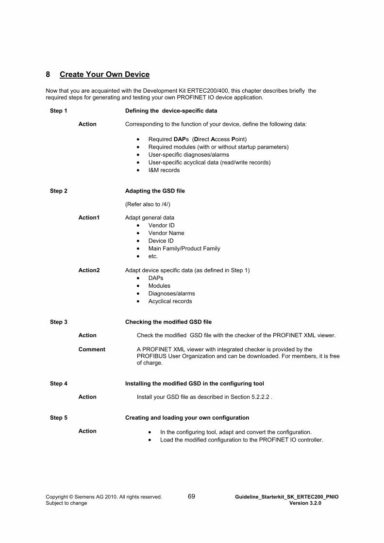
8 Create Your Own Device Now that you are acquainted with the Development Kit ERTEC200/400, this chapter describes briefly the required steps for generating and testing your own PROFINET IO device application.
Step 1 Defining the device-specific data
Action Corresponding to the function of your device, define the following data:
Required DAPs (Direct Access Point) Required modules (with or without startup parameters) User-specific diagnoses/alarms User-specific acyclical data (read/write records) I&M records
Step 2 Adapting the GSD file (Refer also to /4/)
Action1 Adapt general data Vendor ID Vendor Name Device ID Main Family/Product Family etc.
Action2 Adapt device specific data (as defined in Step 1)
DAPs Modules Diagnoses/alarms Acyclical records
Step 3 Checking the modified GSD file
Action Check the modified GSD file with the checker of the PROFINET XML viewer.
Comment A PROFINET XML viewer with integrated checker is provided by the PROFIBUS User Organization and can be downloaded. For members, it is free of charge.
Step 4 Installing the modified GSD in the configuring tool
Action Install your GSD file as described in Section 5.2.2.2 .
Step 5 Creating and loading your own configuration
Action In the configuring tool, adapt and convert the configuration. Load the modified configuration to the PROFINET IO controller.
Copyright © Siemens AG 2010. All rights reserved. 69 Guideline_Starterkit_SK_ERTEC200_PNIO Subject to change Version 3.2.0
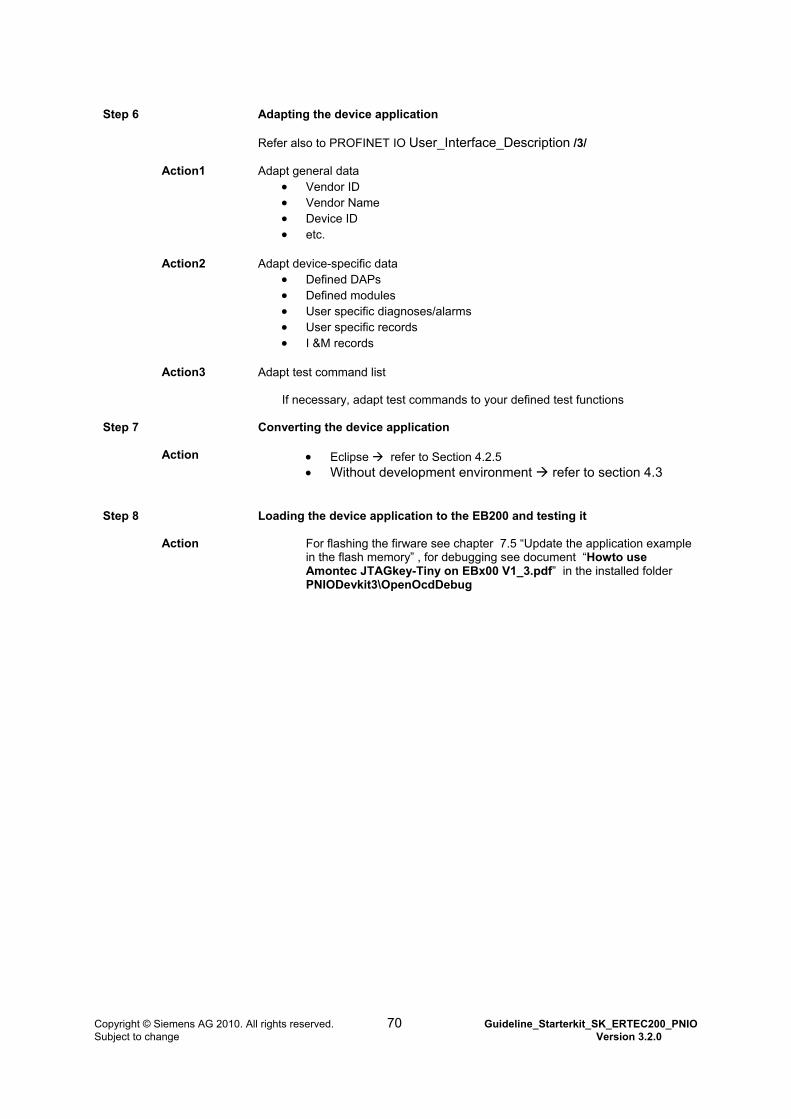
Step 6 Adapting the device application
Refer also to PROFINET IO User_Interface_Description /3/
Action1 Adapt general data Vendor ID Vendor Name Device ID etc.
Action2 Adapt device-specific data
Defined DAPs Defined modules User specific diagnoses/alarms User specific records I &M records
Action3 Adapt test command list
If necessary, adapt test commands to your defined test functions
Step 7 Converting the device application
Action Eclipse refer to Section 4.2.5
Without development environment refer to section 4.3
Step 8 Loading the device application to the EB200 and testing it
Action For flashing the firware see chapter 7.5 “Update the application example
in the flash memory” , for debugging see document “Howto use Amontec JTAGkey-Tiny on EBx00 V1_3.pdf” in the installed folder PNIODevkit3\OpenOcdDebug
Copyright © Siemens AG 2010. All rights reserved. 70 Guideline_Starterkit_SK_ERTEC200_PNIO Subject to change Version 3.2.0

Copyright © Siemens AG 2010. All rights reserved. 71 Guideline_Starterkit_SK_ERTEC200_PNIO Subject to change Version 3.2.0
9 Other
9.1 Abbreviations/List of Terms:
AR Application Relation BSP Board Support Package CP1616 Communications Processor 1616 GSDML Generic Station Description Markup Language IOCR Input Output Communication Relation IRT Isochronous RealTime OS Operating System PDEV Physical Device PN-IO PROFINET IO PNO PROFIBUS Nutzer Organisation (user organization) RT Class Realtime class according to the PROFINET IO specification
9.2 Bibliography:
/1/ GSDML Specification for PROFINET IO Version 2.25 or higher PROFIBUS Nutzerorganisation e.V. /2/ EB200 Manual V1.1.4 (EB200_ Manual_V114.PDF) or /3/ PNIO_DK_User_Interface_Description_V3.2.0
(PNIO_DK_ User_Interface_Description _V320.PDF); /4/ GSDML-Getting Started V1.1 (GSDML_GettingStarted.pdf); /5/ PROFINET IO Application Layer Service Definition &
PROFINET IO Application Layer Protocol Specification (Downloadable from PNO Website http://profibus.com)