Embed Size (px)
Citation preview
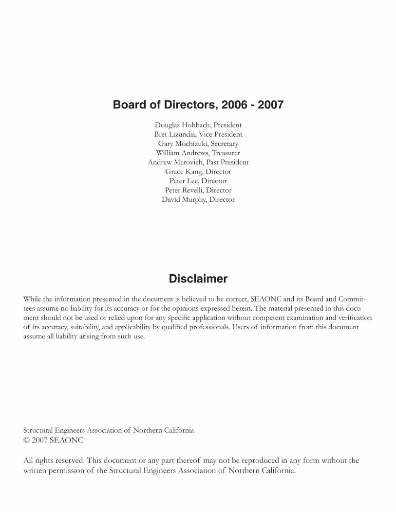
STRUCTURAL ENGINEERS ASSOCIATION OF NORTHERN CALIFORNIA
GUIDELINES FOR REVIEW OFWELDING PROCEDURE SPECIFICATIONS
Prepared by theSEAONC Construction Quality Assurance Committee
February 2007
Board of Directors, 2006 - 2007
Douglas Hohbach, PresidentBret Lizundia, Vice President
Gary Mochizuki, SecretaryWilliam Andrews, Treasurer
Andrew Merovich, Past PresidentGrace Kang, Director
Peter Lee, DirectorPeter Revelli, Director
David Murphy, Director
Disclaimer
While the information presented in the document is believed to be correct, SEAONC and its Board and Commit-tees assume no liability for its accuracy or for the opinions expressed herein. The material presented in this docu-ment should not be used or relied upon for any specific application without competent examination and verification of its accuracy, suitability, and applicability by qualified professionals. Users of information from this document assume all liability arising from such use.
Structural Engineers Association of Northern California© 2007 SEAONC
All rights reserved. This document or any part thereof may not be reproduced in any form without the written permission of the Structural Engineers Association of Northern California.
STRUCTURAL ENGINEERS ASSOCIATION OF NORTHERN CALIFORNIA
Guidelines for Review of Welding Procedure Specifications
STRUCTURAL ENGINEERS ASSOCIATION OF NORTHERN CALIFORNIA 575 Market Street, Suite 2125San Francisco, CA 94105-2870
Phone: (415) 974-5147 Fax: (415) 764-4915Email: [email protected]://www.seaonc.org
These guidelines were written by members ofthe SEAONC Construction Quality Assurance Committee.
Construction Quality Assurance CommitteeTim Hart, Chair 2005-2007Art Dell, Chair 2003-2005
Terry EglandCliff Craig
Ross EsfandiariDoug WilliamsMark GilliganZan TurnerNeal KanayaDave Palfini
The committee acknowledges the following SEAONC membersfor their comments, suggestions, and assistance.
Merl Isaak
STRUCTURAL ENGINEERS ASSOCIATION OF NORTHERN CALIFORNIA
1
Introduction
Inspections of welded steel structures following the 1994 Northridge earthquake found steel moment frames and other welded connections had fractured with minimal ductility instead of absorbing plastic strains as expected. The causes of these fractures included inadequate oversight, insufficient toughness in the connection weldment, and Welding Procedure Specifi-cations that either did not exist or did not conform to the recognized welding code for structural steel, AWS D1.1, Structural Welding Code – Steel. Testing and research conducted by the FEMA/SAC Joint Venture team and others confirmed these findings. As a result, the im-portance of adhering to strict controls on the welding process, particularly as it relates to welded steel connec-tions that resist seismic forces, has been identified as an important factor in helping to preclude premature failure of welded joints. SEAONC and others are now advo-cating the Engineer of Record (EOR) to take an active role in reviewing and monitoring the welding processes employed by the contractor, including review of welding documents. The 2005 AISC Seismic Provisions for Structural Steel Buildings, for example, requires the EOR to review each Welding Procedure Specification (WPS) used in fabrication and erection. AWS D1.1 describes welding as an engineered process. Requirements are specified for welding elec-trode and usage parameters, equipment, steels to be joined, joint configurations, welder (performance) quali-fications and workmanship for the purpose of produc-ing a sound weld joining the steel materials. AWS provisions for confirming the workman-ship ability of the individual welder, called welder quali-fication (also known as “certification”), are well known
and widely enforced. The importance of the welder qualification in the process is critical and is usually ad-dressed by steel fabricators, erectors, and inspectors prior to production. However, the materials and param-eters of the welding process are often taken for granted and are not always properly documented in the required written form known as the Welding Procedure Specifica-tion. Welders and inspectors who work without a written WPS and rely on their experience may or may not produce good welds. AWS D1.1 mandates that all welding be performed and inspected in accordance with the written WPS “recipe” to help ensure the consistent production of sound welds. A common misconcep-tion is that welds using joints that are “prequalified” (see Definitions) in accordance with AWS D1.1 do not require the written documentation of the WPS, when in fact a written WPS is required for all welds. There are no specific provisions related to WPSs in model building codes such as the Uniform Building Code (UBC) or the International Building Code (IBC). Instead, these documents adopt the AISC Specification for Structural Steel Buildings and the AISC Seismic Provisions for Structural Steel Buildings by reference. The AISC Specifica-tions and Seismic Provisions, in turn, adopt AWS D1.1 by reference. There are additional WPS requirements for “demand-critical welds” (see Definitions) in the 2005 AISC Seismic Provisions and in AWS D1.8, Structural Welding Code – Seismic Supplement, that are in addition to the requirements specified in AWS D1.1. All references in these guidelines to AWS D1.1 are to the 2006 edition.
Guidelines for Review of
Welding Procedure Specifications
SEAONC Construction Quality Assurance Committee
STRUCTURAL ENGINEERS ASSOCIATION OF NORTHERN CALIFORNIA
2
Purpose
This document has been produced to inform and educate structural engineers about WPSs and their role in the quality assurance of welded connections. Welding consists of complicated and specialized pro-cesses. The structural engineer should have an under-standing of the organizational relationships and process-es by which a specified weld on a drawing is converted to a finished connection. The structural engineer should be aware of the definition, use, purpose of, and differ-ence between the WPS, procedure qualification, and welder qualification. The engineer should specify submittal of WPSs analogous to other submittals such as concrete mix designs and shop drawings. The contractor is respon-sible for preparing the WPSs. Although earlier editions of AWS D1.1 specifically required engineer approval of some or all WPSs, it currently only states that “The En-gineer shall determine the suitability of all joint details to be used in a welded assembly.” The newly released AWS D1.8, “Structural Welding Code – Seismic Supplement”, appli-cable to welded joints designed in accordance with AISC Seismic Provisions for Structural Steel Buildings, also does not include a requirement for WPS review by the EOR, instead focusing on the engineer’s responsibility to identify and specify the details of welded joints in the seismic load-resisting system. However, as referenced above, WPSs for weldments in structures designed in ac-cordance with AISC Seismic do require approval by the EOR. This document is intended to help engineers understand and review WPS submittals without addi-tional specialized expertise in the detailed requirements of welding. It is not recommended that the engineer at-tempt a WPS review if he or she does not feel technical-ly qualified. A welding, metallurgical, or testing agency consultant can be called in for a more technical review if necessary. Any approval or comments provided by the engineer should be based on his or her own expertise, or the recommendations of a qualified consultant. These guidelines have been updated from the original document published by SEAONC in 1997. In addi-tion to updating all references to AWS and AISC sec-
tions and other editorial revisions, these guidelines were amended to incorporate welding practices, code provi-sions, and other aspects of construction applicable to Welding Procedure Specifications that have changed since the original publication.
Definitions and Terminology
Demand-critical welds: Welds that are expected to be stressed at or beyond their yield strength during seismic loading and exhibit inelastic behavior without sustaining substantial damage or fracture. The EOR must specify which welds are demand-critical on the drawings and/or in the project specifications. Such welds have additional material and verification requirements that are more stringent than what is required for other welds. Specific provisions of AWS D1.8 and AISC Seismic also apply to these welds. As a result, separate WPSs may be needed for demand-critical weld joints that have the same geom-etry as welds that are not so designated.
Essential variable: A welding process, base metal or joint detail parameter that must be specified and limited in the WPS. Information on essential variables are in AWS D1.1, Sections 3.6 and 4.7. For prequalified proce-dures, changes outside the limits of prequalified essential variables require qualification testing, new PQR(s) and a revised WPS. For WPSs qualified by testing, changes outside the limits of essential variables require additional qualification testing, new PQRs and a revised WPS. Joint: A single element of a connection where two or more ends, surfaces, or edges are attached by welding, or according to AWS D1.1. The junction of members or the edges of members that are to be joined or have been joined. Nonessential variable: A welding process, base metal or joint detail parameter that must be specified in the WPS but may be changed during use. A change outside the limits of a nonessential variable does not require a revision to the WPS.
STRUCTURAL ENGINEERS ASSOCIATION OF NORTHERN CALIFORNIA
3
Prequalified WPS: A WPS that is exempt from qualifi-cation testing according to AWS D1.1.
Procedure Qualification: The demonstration by speci-fied tests that welds made by a specific procedure can meet prescribed standards. Procedure Qualification Test Record (PQR): Written documentation of the welding parameters details and test results of a qualification test piece that demonstrate that welds using a particular WPS meet prescribed stan-dards. A PQR is not required for prequalified WPSs.
Weldment: An assembly whose components are joined by welding. Welder Qualification: The demonstration, by speci-fied tests, of a welder’s ability to produce welds meeting prescribed standards. Documented evidence of qualifi-cation is often called “certification.”
Welding Procedure: Detailed methods and practices required to produce an acceptable weldment, including weld processes, connections, joint welding procedures, joint details, preheat, inspection requirements, sequence, shrinkage allowance, postheat, and any other factors. Welding Procedure Specification (WPS): A docu-ment detailing the method and the welding variables required to produce a welded joint. It directs the welder how to weld a specific joint, and includes requirements such as joint preparation, weld process, preheat, elec-trode type and diameter, voltage and current, and travel speed. Its purpose is to assure consistent production of sound welds. The WPS is the focus of these guidelines.
Qualification Requirements
AWS D1.1, Section 4 defines the qualification require-ments for both WPSs and individual welders.
WPS Documenting welding processes and variables in a written WPS provides a standard method for repro-ducing welds. A qualified WPS establishes that a welded
joint proposed for fabrication meets AWS D1.1 require-ments for weld quality. WPSs are qualified by testing according to procedures outlined in the code. How-ever, some WPSs that use established procedures are “prequalified” and exempt from testing.
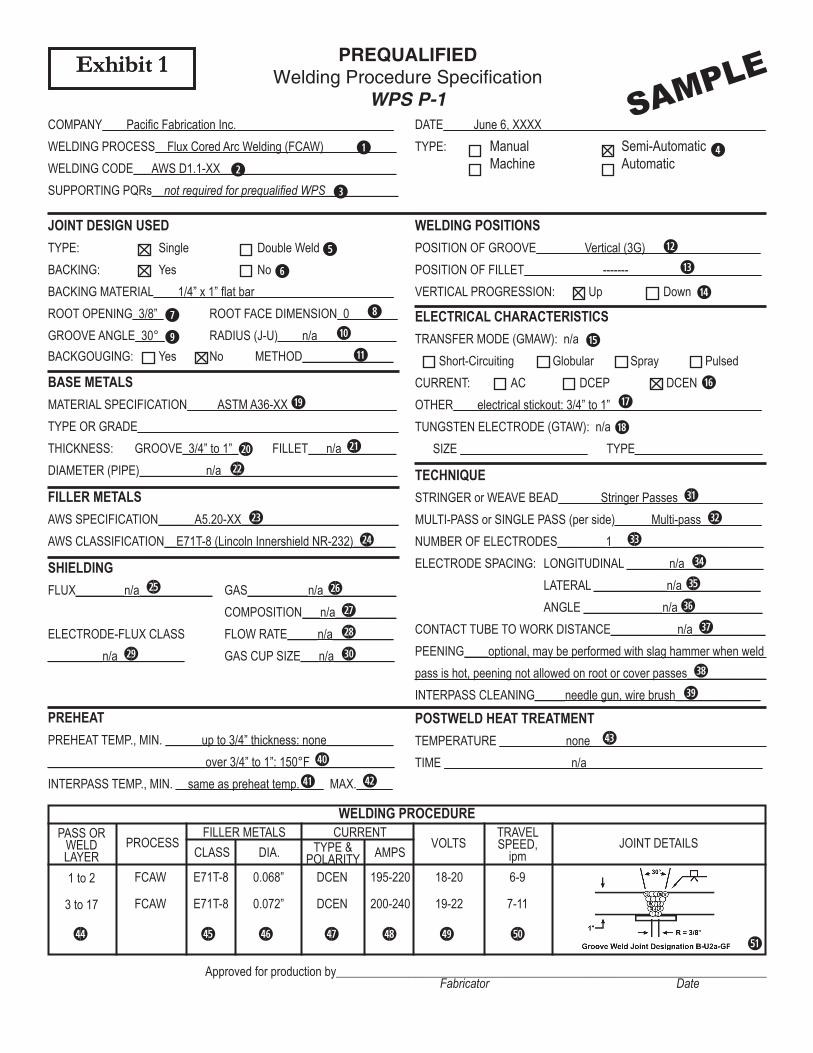
Prequalified WPS In AWS D1.1, a WPS is considered to be prequalified if the selected joint configuration, welding process and variables, and other parameters conform to the mandatory code requirements. A WPS that meets the criteria specified in AWS D1.1, Section 3 is exempt from qualification testing. Although prequalified procedures are exempt from tests, AWS D1.1 does require that the contractor prepare written WPSs for the joints to be used in fabrica-tion. These specifications indicate the limits and re-quirements for material and welding variables, providing documentation that the joint welding meets the require-ments for prequalified status. A sample prequalified WPS is included as Exhibit 1.
WPS Qualified by Testing A WPS that is not prequalified must be qualified by testing according to the requirements of AWS D1.1, Section 4.1.1. Qualification tests are intended to dem-onstrate that a welded joint using a specific WPS meets the prescribed standards of the code. The contractor or fabricator is required to make a test sample, typically a butt-jointed plate using the joint in the proposed WPS, for mechanical testing and evaluation. In preparing the test plate, the welder must follow the written details in the proposed WPS. A sample WPS qualified by testing is included as Exhibit 2. The test plate configurations and dimensions are shown in AWS D1.1, Section 4. The test plate is welded under the conditions simulating the actual production work. The number and types of test specimens to be removed from the completed test plate are shown in AWS D1.1, Tables 4.2-4.4. Tests may include visual inspection, tensile strength, guided bends, macroetches, radiography, and impact tests. If the test results do not meet the requirements of AWS D1.1 or project specifi-cations, then a new WPS must be prepared and qualified
STRUCTURAL ENGINEERS ASSOCIATION OF NORTHERN CALIFORNIA
4
by testing.
Procedure Qualification Record A procedure qualification record (PQR) is writ-ten to document the actual welding variables used and the test results for a proposed WPS. Each WPS quali-fied by testing is supported by one or more PQRs. A sample PQR supporting the WPS in Exhibit 2 is includ-ed as Exhibit 2A. Revision and Requalification If any welding variables are changed in a WPS, then a new WPS may have to be written to reflect the changes. Depending on which variables are changed, the revised WPS may have to be requalified by test-ing. AWS D1.1 specifies the type of changes requiring requalification in Tables 4.5 and 4.6.
Welder Qualification Individual welders must be qualified to perform specific welds. The contractor or fabricator qualifies each welder for each WPS and position. The Com-mentary in AWS D1.1, section C4.18 states, “The welder qualification test is specifically designed to determine a welder’s ability to produce sound welds in any given test joint. After successfully completing the welder quali-fication tests, the welder should be considered to have minimum acceptable qualifications.” AWS D1.1 defines welder qualification require-ments. Each welder’s qualification remains in effect in-definitely unless (1) the welder is not engaged in a given process of welding for which the welder is qualified for a period exceeding six months, or (2) there is some specific reason to question a welder’s ability. A sample welder qualification test record is included as Exhibit 3.
Engineers’ Project Specifications for
WPS
The structural engineer should request WPSs for each type of weld joint to be used on a project. The structural engineer’s request for WPSs will typically ap-pear in the structural steel section of the project specifi-cations. To help ensure that WPSs are used, references
can be included in several places in the section. Sample project requirements for WPS are included as Exhibit 4. An important item to consider for inclusion in the project specifications is a requirement that the manufacturer and specific electrode be stated in the WPS. AWS uses the concept of “essential variable”, which can be considered a parameter that cannot be changed without resubmittal of the WPS by the contrac-tor. Manufacturer and specific electrode are generally not considered essential variables in AWS D1.1. This can allow electrode substitution by the contractor during fabrication without review by the engineer or the testing agency. AWS D1.8 and AISC Seismic now require that the electrode manufacturer and trade name be included in any WPS for demand-critical welds. While not re-quired by code, it is recommended that the engineer require the contractor to submit the electrode product data as part of any WPS submittal that includes welds that are part of the seismic load-resisting system, regard-less of whether or not they are designated as demand-critical. The product data should specify the electrode notch toughness, yield strength, chemical composition, and operating parameters. Project specifications may also describe methods of preparation, welding parameters, inspection require-ments, and mitigation methods for rejected welds. Ad-ditional requirements, such as the sequence of welded construction may also be included in the project speci-fications. These are often referred to as welding proce-dures but should not be confused with WPSs.
Review of WPS
Submittal of WPSs should be in a timely man-ner to allow for adequate review, preferably within the same time frame as the structural steel shop drawings. WPSs should be submitted on all projects that include welds. The structural engineer should review WPSs for completeness and conformance to project specifications. The structural engineer need not be a welding special-ist to be able to review relevant parts of WPSs. As a minimum the structural engineer should verify that the joint details, material thickness and grades, filler materi-als in the design documents are covered by the submit-
STRUCTURAL ENGINEERS ASSOCIATION OF NORTHERN CALIFORNIA
5
ted WPSs. It is recommended that the project testing agency that will be performing the welding inspection review all WPSs, PQRs, and related documents. If the structural engineer determines that additional review is necessary, the documents can be forwarded to a welding consultant. All comments should be forwarded to the structural engineer for incorporation in the WPS sub-mittal response. The project testing agency verifies individual welder qualifications during steel fabrication and erec-tion. Welder qualifications do not ordinarily need to be submitted to the structural engineer for review. Struc-tural engineers should be alert to the possibility of receiving welder qualifications when WPS submittals are required. The submitted WPS and PQR documentation should be appropriate for the specific project. Some fabricators will submit WPSs for all welds that they have paperwork for, including those that are not used on the project. Engineers should discourage this practice when possible, and consider rejecting WPS submittals where it is obvious that inappropriate WPSs are included.
Use During Project
The use of written WPSs during appropriate phases of a project provides the welder with the basic welding and weld joint requirements and provides the inspector and structural engineer with the criteria to evaluate the quality of welding. AWS D1.1, Sections 3.6 and 4.2.3 requires WPSs to be available to those “autho-rized to use or examine them”. Written WPSs should be available at the work site for both welders and inspec-tors. The WPSs provide the welder and inspector the information necessary to set and monitor the variables essential to each welding process and weld joint con-figuration. The inspector can then assure that proper welding parameters are being followed or note devia-tions. The structural engineer should promptly address any nonconformance to an approved WPS.

STRUCTURAL ENGINEERS ASSOCIATION OF NORTHERN CALIFORNIA
Exhibits
Exhibit 1 PREQUALIFIED Welding Procedure SpecificationExhibit 2 QUALIFIED BY TESTING Welding Procedure SpecificationExhibit 2A Procedure Qualification RecordExhibit 3 Welder Performance Qualification Test RecordExhibit 4 Project Specification
PREQUALIFIED
Welding Procedure SpecificationWPS P-1
COMPANY____Pacific Fabrication Inc.__________________________WELDING PROCESS__Flux Cored Arc Welding (FCAW)____________WELDING CODE___AWS D1.1-XX_____________________________SUPPORTING PQRs__not required for prequalified WPS____________
DATE_____June 6, XXXX_____________________________________TYPE: Manual Semi-Automatic Machine Automatic
JOINT DESIGN USEDTYPE: Single Double WeldBACKING: Yes NoBACKING MATERIAL____1/4” x 1” flat bar_______________________ROOT OPENING_3/8”_ ROOT FACE DIMENSION_0________GROOVE ANGLE_30°_ RADIUS (J-U)____n/a_____________BACKGOUGING: Yes No METHOD_______________
WELDING POSITIONSPOSITION OF GROOVE________Vertical (3G)___________________POSITION OF FILLET_____________-------______________________VERTICAL PROGRESSION: Up Down
BASE METALSMATERIAL SPECIFICATION_____ASTM A36-XX__________________TYPE OR GRADE___________________________________________THICKNESS: GROOVE_3/4” to 1”_ FILLET___n/a_________DIAMETER (PIPE)___________n/a_____________________________
FILLER METALSAWS SPECIFICATION______A5.20-XX__________________________AWS CLASSIFICATION__E71T-8 (Lincoln Innershield NR-232)_______
SHIELDINGFLUX________n/a____________ GAS__________n/a____________ COMPOSITION___n/a__________ELECTRODE-FLUX CLASS FLOW RATE_____n/a___________________n/a___________ GAS CUP SIZE___n/a__________
ELECTRICAL CHARACTERISTICSTRANSFER MODE (GMAW): n/a Short-Circuiting Globular Spray PulsedCURRENT: AC DCEP DCENOTHER____electrical stickout: 3/4” to 1”_________________________TUNGSTEN ELECTRODE (GTAW): n/a SIZE _____________________ TYPE_____________________
TECHNIQUESTRINGER or WEAVE BEAD_______Stringer Passes______________MULTI-PASS or SINGLE PASS (per side)______Multi-pass__________NUMBER OF ELECTRODES________1_________________________ELECTRODE SPACING: LONGITUDINAL _______n/a_____________ LATERAL ____________n/a_____________ ANGLE _____________n/a______________CONTACT TUBE TO WORK DISTANCE___________n/a____________PEENING____optional, may be performed with slag hammer when weld pass is hot, peening not allowed on root or cover passes_____________INTERPASS CLEANING_____needle gun, wire brush______________
PREHEATPREHEAT TEMP., MIN. ______up to 3/4” thickness: none_____________________________________over 3/4” to 1”: 150°F______________INTERPASS TEMP., MIN. __same as preheat temp.____ MAX.______
POSTWELD HEAT TREATMENTTEMPERATURE ___________none_____________________________TIME _____________________n/a_____________________________
SAMPLE
WELDING PROCEDUREPASS OR
WELD LAYER
PROCESSFILLER METALS CURRENT
VOLTSTRAVEL SPEED,
ipmJOINT DETAILSCLASS DIA. TYPE &
POLARITY AMPS
1 to 2
3 to 17
FCAW
FCAW
E71T-8
E71T-8
0.068”
0.072”
DCEN
DCEN
195-220
200-240
18-20
19-22
6-9
7-11
Approved for production by_______________________________________________________________________ Fabricator Date
Exhibit 1Exhibit 1
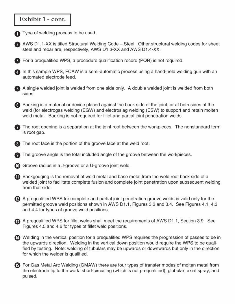
Exhibit 1 - cont.
Type of welding process to be used.
AWS D1.1-XX is titled Structural Welding Code – Steel. Other structural welding codes for sheet steel and rebar are, respectively, AWS D1.3-XX and AWS D1.4-XX.
For a prequalified WPS, a procedure qualification record (PQR) is not required.
In this sample WPS, FCAW is a semi-automatic process using a hand-held welding gun with an automated electrode feed.
A single welded joint is welded from one side only. A double welded joint is welded from both sides.
Backing is a material or device placed against the back side of the joint, or at both sides of the weld (for electrogas welding (EGW) and electroslag welding (ESW) to support and retain molten weld metal. Backing is not required for fillet and partial joint penetration welds.
The root opening is a separation at the joint root between the workpieces. The nonstandard term is root gap.
The root face is the portion of the groove face at the weld root.
The groove angle is the total included angle of the groove between the workpieces.
Groove radius in a J-groove or a U-groove joint weld.
Backgouging is the removal of weld metal and base metal from the weld root back side of a welded joint to facilitate complete fusion and complete joint penetration upon subsequent welding from that side.
A prequalified WPS for complete and partial joint penetration groove welds is valid only for the permitted groove weld positions shown in AWS D1.1, Figures 3.3 and 3.4. See Figures 4.1, 4.3 and 4.4 for types of groove weld positions.
A prequalified WPS for fillet welds shall meet the requirements of AWS D1.1, Section 3.9. See Figures 4.5 and 4.6 for types of fillet weld positions.
Welding in the vertical position for a prequalified WPS requires the progression of passes to be in the upwards direction. Welding in the vertical down position would require the WPS to be quali-fied by testing. Note: welding of tubulars may be upwards or downwards but only in the direction for which the welder is qualified.
For Gas Metal Arc Welding (GMAW) there are four types of transfer modes of molten metal from the electrode tip to the work: short-circuiting (which is not prequalified), globular, axial spray, and pulsed.
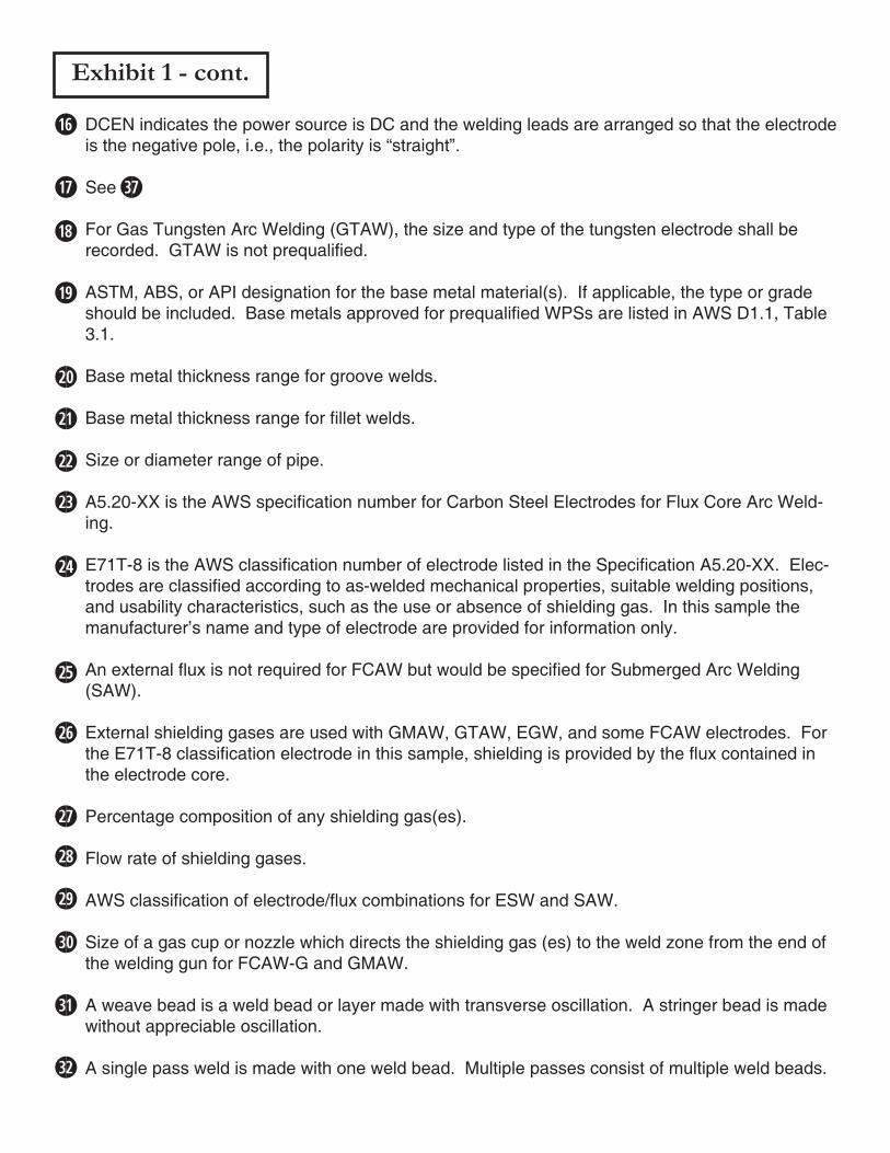
Exhibit 1 - cont.
DCEN indicates the power source is DC and the welding leads are arranged so that the electrode is the negative pole, i.e., the polarity is “straight”.
See
For Gas Tungsten Arc Welding (GTAW), the size and type of the tungsten electrode shall be recorded. GTAW is not prequalified.
ASTM, ABS, or API designation for the base metal material(s). If applicable, the type or grade should be included. Base metals approved for prequalified WPSs are listed in AWS D1.1, Table 3.1.
Base metal thickness range for groove welds.
Base metal thickness range for fillet welds.
Size or diameter range of pipe.
A5.20-XX is the AWS specification number for Carbon Steel Electrodes for Flux Core Arc Weld-ing.
E71T-8 is the AWS classification number of electrode listed in the Specification A5.20-XX. Elec-trodes are classified according to as-welded mechanical properties, suitable welding positions, and usability characteristics, such as the use or absence of shielding gas. In this sample the manufacturer’s name and type of electrode are provided for information only.
An external flux is not required for FCAW but would be specified for Submerged Arc Welding (SAW).
External shielding gases are used with GMAW, GTAW, EGW, and some FCAW electrodes. For the E71T-8 classification electrode in this sample, shielding is provided by the flux contained in the electrode core.
Percentage composition of any shielding gas(es).
Flow rate of shielding gases.
AWS classification of electrode/flux combinations for ESW and SAW.
Size of a gas cup or nozzle which directs the shielding gas (es) to the weld zone from the end of the welding gun for FCAW-G and GMAW.
A weave bead is a weld bead or layer made with transverse oscillation. A stringer bead is made without appreciable oscillation.
A single pass weld is made with one weld bead. Multiple passes consist of multiple weld beads.
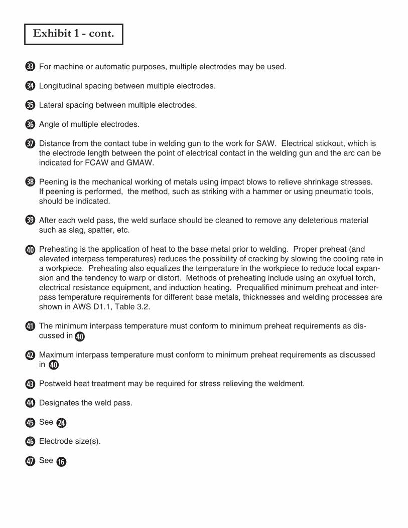
Exhibit 1 - cont.
For machine or automatic purposes, multiple electrodes may be used.
Longitudinal spacing between multiple electrodes.
Lateral spacing between multiple electrodes.
Angle of multiple electrodes.
Distance from the contact tube in welding gun to the work for SAW. Electrical stickout, which is the electrode length between the point of electrical contact in the welding gun and the arc can be indicated for FCAW and GMAW.
Peening is the mechanical working of metals using impact blows to relieve shrinkage stresses. If peening is performed, the method, such as striking with a hammer or using pneumatic tools, should be indicated.
After each weld pass, the weld surface should be cleaned to remove any deleterious material such as slag, spatter, etc.
Preheating is the application of heat to the base metal prior to welding. Proper preheat (and elevated interpass temperatures) reduces the possibility of cracking by slowing the cooling rate in a workpiece. Preheating also equalizes the temperature in the workpiece to reduce local expan-sion and the tendency to warp or distort. Methods of preheating include using an oxyfuel torch, electrical resistance equipment, and induction heating. Prequalified minimum preheat and inter-pass temperature requirements for different base metals, thicknesses and welding processes are shown in AWS D1.1, Table 3.2.
The minimum interpass temperature must conform to minimum preheat requirements as dis-cussed in
Maximum interpass temperature must conform to minimum preheat requirements as discussed in
Postweld heat treatment may be required for stress relieving the weldment.
Designates the weld pass.
See
Electrode size(s).
See
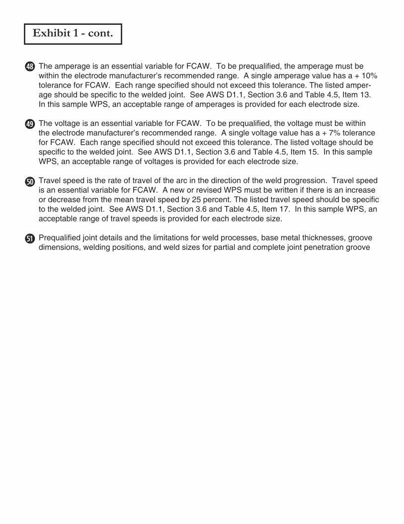
Exhibit 1 - cont.
The amperage is an essential variable for FCAW. To be prequalified, the amperage must be within the electrode manufacturer’s recommended range. A single amperage value has a + 10% tolerance for FCAW. Each range specified should not exceed this tolerance. The listed amper-age should be specific to the welded joint. See AWS D1.1, Section 3.6 and Table 4.5, Item 13. In this sample WPS, an acceptable range of amperages is provided for each electrode size.
The voltage is an essential variable for FCAW. To be prequalified, the voltage must be within the electrode manufacturer’s recommended range. A single voltage value has a + 7% tolerance for FCAW. Each range specified should not exceed this tolerance. The listed voltage should be specific to the welded joint. See AWS D1.1, Section 3.6 and Table 4.5, Item 15. In this sample WPS, an acceptable range of voltages is provided for each electrode size.
Travel speed is the rate of travel of the arc in the direction of the weld progression. Travel speed is an essential variable for FCAW. A new or revised WPS must be written if there is an increase or decrease from the mean travel speed by 25 percent. The listed travel speed should be specific to the welded joint. See AWS D1.1, Section 3.6 and Table 4.5, Item 17. In this sample WPS, an acceptable range of travel speeds is provided for each electrode size.
Prequalified joint details and the limitations for weld processes, base metal thicknesses, groove dimensions, welding positions, and weld sizes for partial and complete joint penetration groove
QUALIFIED BY TESTING
Welding Procedure SpecificationWPS P-2
COMPANY____Pacific Fabrication Inc.__________________________WELDING PROCESS__Shielded Metal Arc Welding (SMAW)_________WELDING CODE___AWS D1.1-XX_____________________________SUPPORTING PQRs__P-2___________________________________
DATE_____January 11, XXXX_________________________________TYPE: Manual Semi-Automatic Machine Automatic
JOINT DESIGN USEDTYPE: Single Double WeldBACKING: Yes NoBACKING MATERIAL____3/16” x 1” flat bar______________________ROOT OPENING_3/8”_ ROOT FACE DIMENSION_0________GROOVE ANGLE_45°_ RADIUS (J-U)____n/a_____________BACKGOUGING: Yes No METHOD_______________
WELDING POSITIONSPOSITION OF GROOVE______Flat (1G), Horizontal (2G)___________POSITION OF FILLET_____________-------______________________VERTICAL PROGRESSION: Up Down
BASE METALSMATERIAL SPECIFICATION_____ASTM A36-XX__________________TYPE OR GRADE___________________________________________THICKNESS: GROOVE_1/2” to 3/4”_ FILLET___n/a_________DIAMETER (PIPE)___________n/a_____________________________
FILLER METALSAWS SPECIFICATION______A5.20-XX__________________________AWS CLASSIFICATION__E7018 (Lincoln Electric LH-70)____________
SHIELDINGFLUX________n/a____________ GAS__________n/a____________ COMPOSITION___n/a__________ELECTRODE-FLUX CLASS FLOW RATE_____n/a___________________n/a___________ GAS CUP SIZE___n/a__________
ELECTRICAL CHARACTERISTICSTRANSFER MODE (GMAW): n/a Short-Circuiting Globular Spray PulsedCURRENT: AC DCEP DCENOTHER____________________________________________________TUNGSTEN ELECTRODE (GTAW): n/a
TECHNIQUESTRINGER or WEAVE BEAD_______Stringer Passes______________MULTI-PASS or SINGLE PASS (per side)______Multi-pass__________NUMBER OF ELECTRODES________1_________________________ELECTRODE SPACING: LONGITUDINAL _______n/a_____________ LATERAL ____________n/a_____________ ANGLE _____________n/a______________CONTACT TUBE TO WORK DISTANCE___________n/a____________PEENING____optional, may be performed with slag hammer when weld pass is hot, peening not allowed on root or cover passes_____________INTERPASS CLEANING_____needle gun, wire brush______________
PREHEATPREHEAT TEMP., MIN. ______________40°F_____________________________________________________________________________INTERPASS TEMP., MIN. __________40°F___________ MAX.______
POSTWELD HEAT TREATMENTTEMPERATURE ___________none_____________________________TIME _____________________n/a_____________________________
Exhibit 2
SAMPLE
WELDING PROCEDUREPASS OR
WELD LAYER
PROCESSFILLER METALS CURRENT
VOLTSTRAVEL SPEED,
ipmJOINT DETAILSCLASS DIA. TYPE &
POLARITY AMPS
1 to 2
3 to 9
SMAW
SMAW
E7018
E7018
1/8”
5/32”
DCEP
DCEP
130-140
150-180
20-21
23-26
8-10
10-15
Approved for production by_______________________________________________________________________ Fabricator Date
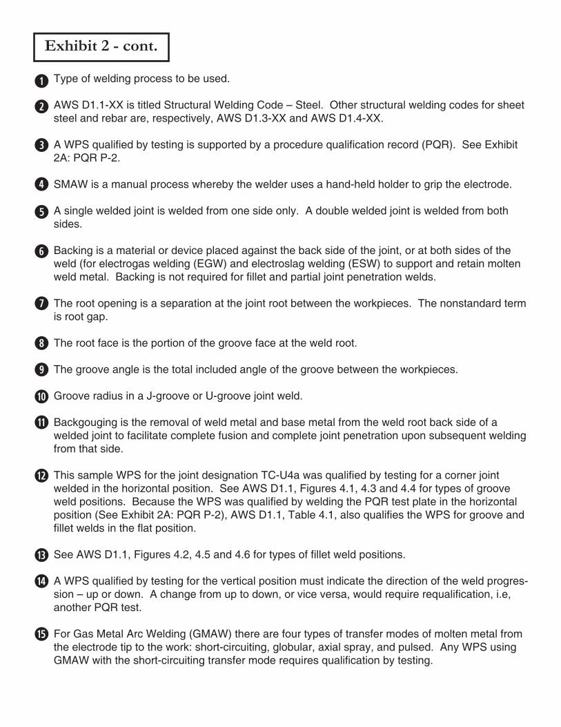
Exhibit 2 - cont.
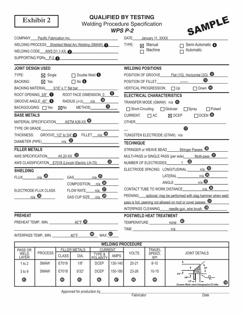
Type of welding process to be used.
AWS D1.1-XX is titled Structural Welding Code – Steel. Other structural welding codes for sheet steel and rebar are, respectively, AWS D1.3-XX and AWS D1.4-XX.
A WPS qualified by testing is supported by a procedure qualification record (PQR). See Exhibit 2A: PQR P-2.
SMAW is a manual process whereby the welder uses a hand-held holder to grip the electrode.
A single welded joint is welded from one side only. A double welded joint is welded from both sides.
Backing is a material or device placed against the back side of the joint, or at both sides of the weld (for electrogas welding (EGW) and electroslag welding (ESW) to support and retain molten weld metal. Backing is not required for fillet and partial joint penetration welds.
The root opening is a separation at the joint root between the workpieces. The nonstandard term is root gap.
The root face is the portion of the groove face at the weld root.
The groove angle is the total included angle of the groove between the workpieces.
Groove radius in a J-groove or U-groove joint weld.
Backgouging is the removal of weld metal and base metal from the weld root back side of a welded joint to facilitate complete fusion and complete joint penetration upon subsequent welding from that side.
This sample WPS for the joint designation TC-U4a was qualified by testing for a corner joint welded in the horizontal position. See AWS D1.1, Figures 4.1, 4.3 and 4.4 for types of groove weld positions. Because the WPS was qualified by welding the PQR test plate in the horizontal position (See Exhibit 2A: PQR P-2), AWS D1.1, Table 4.1, also qualifies the WPS for groove and fillet welds in the flat position.
See AWS D1.1, Figures 4.2, 4.5 and 4.6 for types of fillet weld positions.
A WPS qualified by testing for the vertical position must indicate the direction of the weld progres-sion – up or down. A change from up to down, or vice versa, would require requalification, i.e, another PQR test.
For Gas Metal Arc Welding (GMAW) there are four types of transfer modes of molten metal from the electrode tip to the work: short-circuiting, globular, axial spray, and pulsed. Any WPS using GMAW with the short-circuiting transfer mode requires qualification by testing.
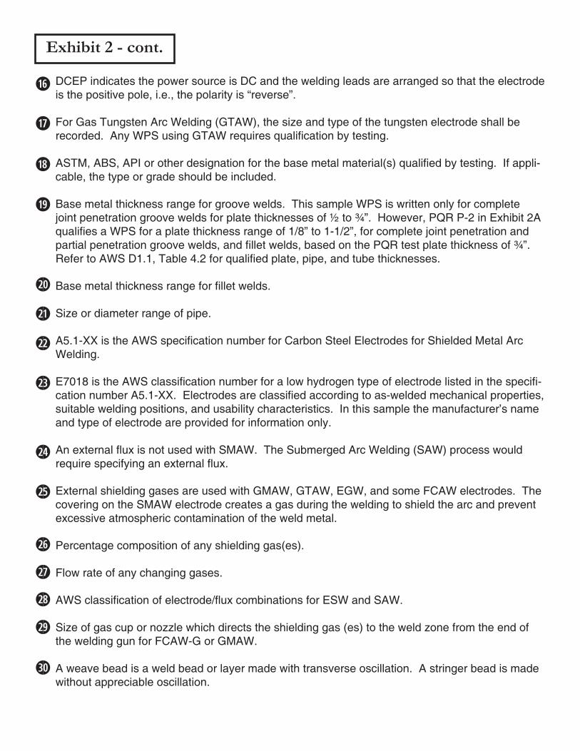
Exhibit 2 - cont.
DCEP indicates the power source is DC and the welding leads are arranged so that the electrode is the positive pole, i.e., the polarity is “reverse”.
For Gas Tungsten Arc Welding (GTAW), the size and type of the tungsten electrode shall be recorded. Any WPS using GTAW requires qualification by testing.
ASTM, ABS, API or other designation for the base metal material(s) qualified by testing. If appli-cable, the type or grade should be included.
Base metal thickness range for groove welds. This sample WPS is written only for complete joint penetration groove welds for plate thicknesses of ½ to ¾”. However, PQR P-2 in Exhibit 2A qualifies a WPS for a plate thickness range of 1/8” to 1-1/2”, for complete joint penetration and partial penetration groove welds, and fillet welds, based on the PQR test plate thickness of ¾”. Refer to AWS D1.1, Table 4.2 for qualified plate, pipe, and tube thicknesses.
Base metal thickness range for fillet welds.
Size or diameter range of pipe.
A5.1-XX is the AWS specification number for Carbon Steel Electrodes for Shielded Metal Arc Welding.
E7018 is the AWS classification number for a low hydrogen type of electrode listed in the specifi-cation number A5.1-XX. Electrodes are classified according to as-welded mechanical properties, suitable welding positions, and usability characteristics. In this sample the manufacturer’s name and type of electrode are provided for information only.
An external flux is not used with SMAW. The Submerged Arc Welding (SAW) process would require specifying an external flux.
External shielding gases are used with GMAW, GTAW, EGW, and some FCAW electrodes. The covering on the SMAW electrode creates a gas during the welding to shield the arc and prevent excessive atmospheric contamination of the weld metal.
Percentage composition of any shielding gas(es).
Flow rate of any changing gases.
AWS classification of electrode/flux combinations for ESW and SAW.
Size of gas cup or nozzle which directs the shielding gas (es) to the weld zone from the end of the welding gun for FCAW-G or GMAW.
A weave bead is a weld bead or layer made with transverse oscillation. A stringer bead is made without appreciable oscillation.
A single pass weld is made with one weld bead. Multiple passes consist of multiple weld beads.
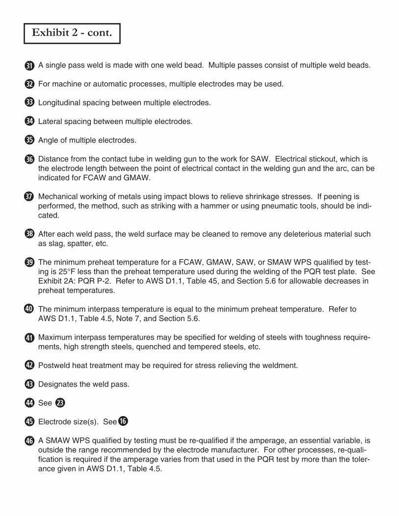
For machine or automatic processes, multiple electrodes may be used.
Longitudinal spacing between multiple electrodes.
Lateral spacing between multiple electrodes.
Angle of multiple electrodes.
Distance from the contact tube in welding gun to the work for SAW. Electrical stickout, which is the electrode length between the point of electrical contact in the welding gun and the arc, can be indicated for FCAW and GMAW.
Mechanical working of metals using impact blows to relieve shrinkage stresses. If peening is performed, the method, such as striking with a hammer or using pneumatic tools, should be indi-cated.
After each weld pass, the weld surface may be cleaned to remove any deleterious material such as slag, spatter, etc.
The minimum preheat temperature for a FCAW, GMAW, SAW, or SMAW WPS qualified by test-ing is 25°F less than the preheat temperature used during the welding of the PQR test plate. See Exhibit 2A: PQR P-2. Refer to AWS D1.1, Table 45, and Section 5.6 for allowable decreases in preheat temperatures.
The minimum interpass temperature is equal to the minimum preheat temperature. Refer to AWS D1.1, Table 4.5, Note 7, and Section 5.6.
Maximum interpass temperatures may be specified for welding of steels with toughness require-ments, high strength steels, quenched and tempered steels, etc.
Postweld heat treatment may be required for stress relieving the weldment.
Designates the weld pass.
See
Electrode size(s). See
A SMAW WPS qualified by testing must be re-qualified if the amperage, an essential variable, is outside the range recommended by the electrode manufacturer. For other processes, re-quali-fication is required if the amperage varies from that used in the PQR test by more than the toler-ance given in AWS D1.1, Table 4.5.
Exhibit 2 - cont.

Exhibit 2 - cont.
A SMAW WPS qualified by testing must be re-qualified if the voltage, an essential variable, is outside the range recommended by the electrode manufacturer. For other processes, re-qualifi-cation is required if the voltage varies from that used in the PQR test by more than the tolerance given in AWS D1.1, Table 4.5.
A SMAW WPS qualified by testing must be re-qualified of the voltage, an essential variable, is outside the range recommended by the electrode manufacturer. For other processes, re-qualifi-cation is required if the voltage varies from that used in the PQR test by more than the tolerance given in AWS D1.1, Table 4.5.
Travel speed is the speed of the arc in the direction of the weld progression. Travel speed is not an essential variable for SMAW. However, for other processes, requalification is required if the travel speed varies from that used in the PQR test by more than the tolerance given in AWS D1.1, Table 4.5.
Joint details for the corner weld joint.

GUIDED BEND TESTS
Procedure Qualification RecordPQR P-2
COMPANY____Pacific Fabrication Inc.__________________________WELDING PROCESS__Shielded Metal Arc Welding (SMAW)_________
DATE_____January 11, XXXX_________________________________WELDING CODE___AWS D1.1-XX_____________________________
Exhibit 2A SAMPLE
WELDING POSITION _______Horizontal (2G)____________________BASE METAL _______ASTM A36-XX, 3/4” plate___________________BACKING MATERIAL ___3/16” x 1” flat bar_______________________BACKGOUGING: Yes NoPREHEAT TEMP. ______none (65°F ambient)____________________INTERPASS TEMP. _________325°F___________________________POSTWELD HEAT TREATMENT ____none______________________INTERPASS CLEANING _____needle gun, wire brush______________WELDER’S NAME ________Ryan F. Tana_______________________WELDER’S SOCIAL SECURITY NO. _____666-55-7777____________
TEST ASSEMBLY _AWS D1.1-XX, Fig.4.10 [Fig.5.10]_______________FILLER METAL _____AWS A5.1-XX, E7018______________________ELECTRODE SIZE __________1/8” dia._________________________CURRENT: AC DCEP DCENVOLTAGE ______20_____ AMPERAGE _______130_____ARC TRAVEL SPEED _________8-10 ipm_______________________STRINGER or WEAVE BEAD __________Stringer_________________MULTI-PASS or SINGLE PASS (per side) ______Multi-pass__________PEENING ______________none_______________________________TEST DATE ___________January 9, XXXX_______________________
TEST RESULTSVISUAL INSPECTION
Appearance __Acceptable__ Undercut __Acceptable__ Piping Porosity __Acceptable__ Convexity __-----------__
RADIOGRAPHIC EXAMINATION or ULTRASONIC TESTINGRT Report No. __96-101__ Result __Passed__ UT Report No. ___-------___ Result __--------__
SpecimenNo.
ResultType of Bend Remarks
1234
SideSideSideSide
PassedPassedPassedPassed
complete fusion, no discontinuitiescomplete fusion, no discontinuitiescomplete fusion, no discontinuitiescomplete fusion, no discontinuities
TENSILE TESTSSpecimen
No.Width,
in.Thickness,
in.Area,sq. in.
UltimateTensile Load, lbs.
UltimateTensile Stress, psi
FractureLocation
12
0.7510.748
0.7470.747
0.5610.599
35,90035,100
64,00062,800
Base MetalBase Metal
Tests conducted by ____Acme Testing Laboratory_______ Lab No. ____Z-1957-24-23____
We, the undersigned, certify that the information in this record is correct, and that the test weld was prepared, welded, and tested in accordance with the requirements of Section 1, Part B, [Section 5, Part B] of AWS D1.1-XX,Structural Welding Code - Steel.
Signed by ________________________________________________________________
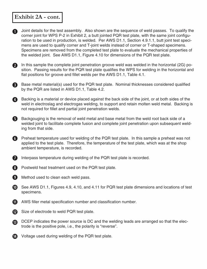
Exhibit 2A - cont.
Joint details for the test assembly. Also shown are the sequence of weld passes. To qualify the corner joint for WPS P-2 in Exhibit 2, a butt jointed PQR test plate, with the same joint configu-ration to be used in production, is welded. Per AWS D1.1, Section 4.9.1.1, butt joint test speci-mens are used to qualify corner and T-joint welds instead of corner or T-shaped specimens. Specimens are removed from the completed test plate to evaluate the mechanical properties of the welded joint. See AWS D1.1, Figure 4.10 for dimensions of the PQR test plate.
In this sample the complete joint penetration groove weld was welded in the horizontal (2G) po-sition. Passing results for the PQR test plate qualifies the WPS for welding in the horizontal and flat positions for groove and fillet welds per the AWS D1.1, Table 4.1.
Base metal material(s) used for the PQR test plate. Nominal thicknesses considered qualified by the PQR are listed in AWS D1.1, Table 4.2.
Backing is a material or device placed against the back side of the joint, or at both sides of the weld in electroslag and electrogas welding, to support and retain molten weld metal. Backing is not required for fillet and partial joint penetration welds.
Backgouging is the removal of weld metal and base metal from the weld root back side of a welded joint to facilitate complete fusion and complete joint penetration upon subsequent weld-ing from that side.
Preheat temperature used for welding of the PQR test plate. In this sample a preheat was not applied to the test plate. Therefore, the temperature of the test plate, which was at the shop ambient temperature, is recorded.
Interpass temperature during welding of the PQR test plate is recorded.
Postweld heat treatment used on the PQR test plate.
Method used to clean each weld pass.
See AWS D1.1, Figures 4.9, 4.10, and 4.11 for PQR test plate dimensions and locations of test specimens.
AWS filler metal specification number and classification number.
Size of electrode to weld PQR test plate.
DCEP indicates the power source is DC and the welding leads are arranged so that the elec-trode is the positive pole, i.e., the polarity is “reverse”.
Voltage used during welding of the PQR test plate.
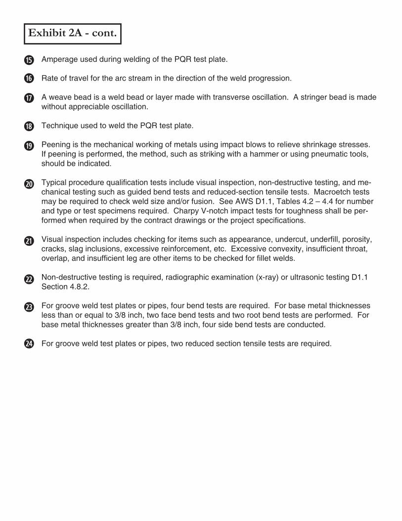
Exhibit 2A - cont.
Amperage used during welding of the PQR test plate.
Rate of travel for the arc stream in the direction of the weld progression.
A weave bead is a weld bead or layer made with transverse oscillation. A stringer bead is made without appreciable oscillation.
Technique used to weld the PQR test plate.
Peening is the mechanical working of metals using impact blows to relieve shrinkage stresses. If peening is performed, the method, such as striking with a hammer or using pneumatic tools, should be indicated.
Typical procedure qualification tests include visual inspection, non-destructive testing, and me-chanical testing such as guided bend tests and reduced-section tensile tests. Macroetch tests may be required to check weld size and/or fusion. See AWS D1.1, Tables 4.2 – 4.4 for number and type or test specimens required. Charpy V-notch impact tests for toughness shall be per-formed when required by the contract drawings or the project specifications.
Visual inspection includes checking for items such as appearance, undercut, underfill, porosity, cracks, slag inclusions, excessive reinforcement, etc. Excessive convexity, insufficient throat, overlap, and insufficient leg are other items to be checked for fillet welds.
Non-destructive testing is required, radiographic examination (x-ray) or ultrasonic testing D1.1 Section 4.8.2.
For groove weld test plates or pipes, four bend tests are required. For base metal thicknesses less than or equal to 3/8 inch, two face bend tests and two root bend tests are performed. For base metal thicknesses greater than 3/8 inch, four side bend tests are conducted.
For groove weld test plates or pipes, two reduced section tensile tests are required.
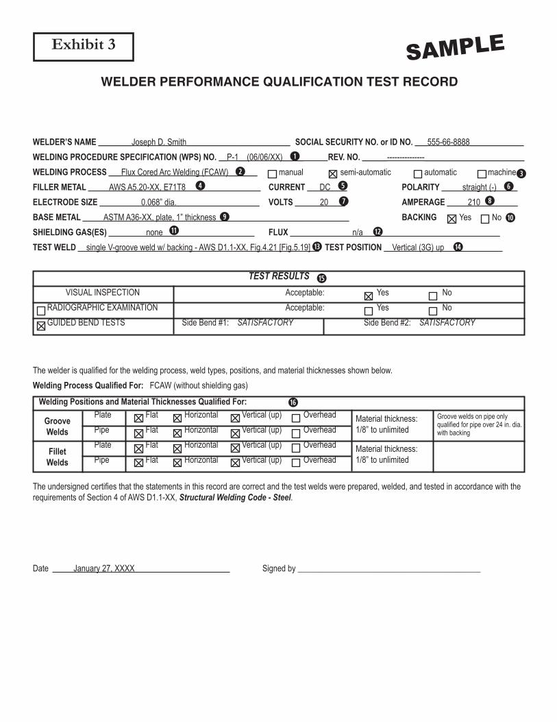
WELDER PERFORMANCE QUALIFICATION TEST RECORD
WELDER’S NAME ________Joseph D. Smith_________________________ SOCIAL SECURITY NO. or ID NO. ___555-66-8888_____________WELDING PROCEDURE SPECIFICATION (WPS) NO. __P-1__(06/06/XX)_____ REV. NO. ______---------------________________________WELDING PROCESS ___Flux Cored Arc Welding (FCAW)_______ manual semi-automatic automatic machineFILLER METAL _____AWS A5.20-XX, E71T8__________________ CURRENT ___DC____ POLARITY _____straight (-)_____ELECTRODE SIZE __________0.068” dia.____________________ VOLTS ______20____ AMPERAGE _____210_________BASE METAL _____ASTM A36-XX, plate, 1” thickness________________________________ BACKING Yes NoSHIELDING GAS(ES) _________none______________________ FLUX _______________n/a_________________________________TEST WELD __single V-groove weld w/ backing - AWS D1.1-XX, Fig.4.21 [Fig.5.19]__ TEST POSITION __Vertical (3G) up______________
Exhibit 3 SAMPLE
TEST RESULTSVISUAL INSPECTION
RADIOGRAPHIC EXAMINATION GUIDED BEND TESTS
Acceptable: Yes No Acceptable: Yes No Side Bend #1: SATISFACTORY Side Bend #2: SATISFACTORY
The welder is qualified for the welding process, weld types, positions, and material thicknesses shown below.Welding Process Qualified For: FCAW (without shielding gas)
Welding Positions and Material Thicknesses Qualified For: Plate Flat Horizontal Vertical (up) Overhead Pipe Flat Horizontal Vertical (up) Overhead Plate Flat Horizontal Vertical (up) Overhead Pipe Flat Horizontal Vertical (up) Overhead
GrooveWelds
FilletWelds
Material thickness:1/8” to unlimited
Material thickness:1/8” to unlimited
Groove welds on pipe only qualified for pipe over 24 in. dia. with backing
The undersigned certifies that the statements in this record are correct and the test welds were prepared, welded, and tested in accordance with the requirements of Section 4 of AWS D1.1-XX, Structural Welding Code - Steel.
Date _____January 27, XXXX_______________ Signed by ____________________________________________
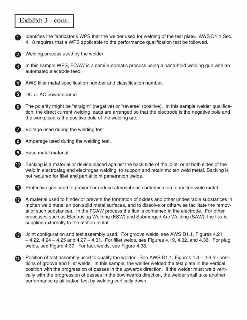
Exhibit 3 - cont.
Identifies the fabricator’s WPS that the welder used for welding of the test plate. AWS D1.1 Sec. 4.18 requires that a WPS applicable to the performance qualification test be followed.
Welding process used by the welder.
In this sample WPS, FCAW is a semi-automatic process using a hand-held welding gun with an automated electrode feed.
AWS filler metal specification number and classification number.
DC or AC power source.
The polarity might be “straight” (negative) or “reverse” (positive). In this sample welder qualifica-tion, the direct current welding leads are arranged so that the electrode is the negative pole and the workpiece is the positive pole of the welding arc.
Voltage used during the welding test.
Amperage used during the welding test.
Base metal material.
Backing is a material or device placed against the back side of the joint, or at both sides of the weld in electroslag and electrogas welding, to support and retain molten weld metal. Backing is not required for fillet and partial joint penetration welds.
Protective gas used to prevent or reduce atmospheric contamination to molten weld metal.
A material used to hinder or prevent the formation of oxides and other undesirable substances in molten weld metal an don solid metal surfaces, and to dissolve or otherwise facilitate the remov-al of such substances. In the FCAW process the flux is contained in the electrode. For other processes such as Electroslag Welding (ESW) and Submerged Arc Welding (SAW), the flux is supplied externally to the molten metal.
Joint configuration and test assembly used. For groove welds, see AWS D1.1, Figures 4.21 – 4.22, 4.24 – 4.25 and 4.27 – 4.31. For fillet welds, see Figures 4.19, 4.32, and 4.36. For plug welds, see Figure 4.37. For tack welds, see Figure 4.38.
Position of test assembly used to qualify the welder. See AWS D1.1, Figures 4.3 – 4.6 for posi-tions of groove and fillet welds. In this sample, the welder welded the test plate in the vertical position with the progression of passes in the upwards direction. If the welder must weld verti-cally with the progression of passes in the downwards direction, the welder shall take another performance qualification test by welding vertically down.
Exhibit 3 - cont.
Typical welder performance qualification tests for groove welds include a visual inspection of the welding followed by mechanical testing. Visual inspection includes checking for items such as appearance, undercut, underfill, porosity, cracks, slag inclusions, excessive reinforcement, etc. In this sample, machined specimens were removed from the 1 inch thick welded test plate for two side bend tests. If a test plate is less than or equal to 3/8 inch, one face bend test and one root bend test are required instead of two side bends. In lieu of conducting bend tests, the code states the test assembly can be radiographically examined (x-rayed). Refer to AWS D1.1, Table 4.9 for the required number and type of tests for all configurations of welder performance qualifi-cation test assemblies.
The table indicates the welding positions and material thicknesses for both groove and fillet welds that the welder has been qualified to weld. These are based on the passing test results for the 1 inch test plate welded in the vertical (up) position. See AWS D1.1, Table 4.9, for weld-ing positions qualified, Table 4.10 for material thickness range qualified, and Table 4.11 for welder essential variables requiring requalification.
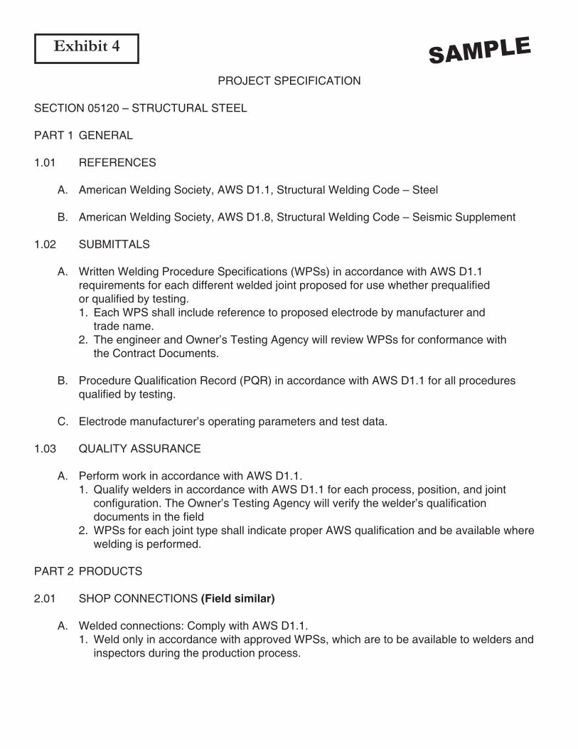
Exhibit 4
PROJECT SPECIFICATION
SECTION 05120 – STRUCTURAL STEEL
PART 1 GENERAL
1.01 REFERENCES
A. American Welding Society, AWS D1.1, Structural Welding Code – Steel B. American Welding Society, AWS D1.8, Structural Welding Code – Seismic Supplement
1.02 SUBMITTALS
A. Written Welding Procedure Specifications (WPSs) in accordance with AWS D1.1 requirements for each different welded joint proposed for use whether prequalified or qualified by testing. 1. Each WPS shall include reference to proposed electrode by manufacturer and trade name. 2. The engineer and Owner’s Testing Agency will review WPSs for conformance with the Contract Documents.
B. Procedure Qualification Record (PQR) in accordance with AWS D1.1 for all procedures qualified by testing.
C. Electrode manufacturer’s operating parameters and test data.
1.03 QUALITY ASSURANCE
A. Perform work in accordance with AWS D1.1. 1. Qualify welders in accordance with AWS D1.1 for each process, position, and joint configuration. The Owner’s Testing Agency will verify the welder’s qualification documents in the field 2. WPSs for each joint type shall indicate proper AWS qualification and be available where welding is performed.
PART 2 PRODUCTS
2.01 SHOP CONNECTIONS (Field similar)
A. Welded connections: Comply with AWS D1.1. 1. Weld only in accordance with approved WPSs, which are to be available to welders and inspectors during the production process.
SAMPLE
PART 3 EXECUTION
3.01 SOURCE QUALITY CONTROL (Field similar)
A. The Owner’s Testing Agency will inspect shop welding for conformance with AWS D1.1 requirements and will verify that welds are made in accordance with approved WPSs.
SAMPLEExhibit 4 - cont.