Embed Size (px)
Citation preview

Guidelines for the Evaluation and Repair of Residential Foundations – Version 2 (Adopted May 1, 2009)
Guidelines for the Evaluation and Repair of Residential Foundations
Version 2
(Adopted May 1, 2009)
By the Texas Section American Society of Civil Engineers
© 2008 Texas Section – American Society of Civil Engineers. All rights reserved. Permission to make electronic or hard copies of this document for personal, non-commercial use is granted without fee, provided that no alterations, additions, or revisions are made to the document and that all copies of the document include this notice and attribution on the first page. Any other use of this document is strictly prohibited without prior written permission of the Texas Section-ASCE. To request permission, call 512-472-8905 or email [email protected].
Guidelines for the Evaluation and Repair of Residential Foundations – Version 2 (Adopted May 1, 2009)
Foreword to Version 2
The Texas Section of the American Society of Civil Engineers (ASCE) adopted Guidelines for
the Evaluation and Repair of Residential Foundations on October 3, 2002, with an effective
date of January 01, 2003. Version 2, presented herein, was adopted on May 1, 2009. For
reference, the following pages present specific changes to Version 2.
The Section began this work in 1999. This effort grew out of the response of many Section
members to the Policy Advisory issued by the Texas Board of Professional Engineers (TBPE)
in 1998, which addressed residential foundation engineering. Many ASCE practitioners
expressed the opinion that technical guidelines should more rightly be created by a technical
society such as ASCE rather than by the TBPE. One goal of the guidelines has been to
provide the TBPE with guidance in their evaluation of complaints brought against engineers
practicing residential foundation engineering.
One committee and two subcommittees were formed to address the raised concerns. One
subcommittee addressed Recommended Practice for the Design of Residential Foundations
(with their work presented in a separate document). The Guidelines for the Evaluation and
Repair of Residential Foundations Subcommittee developed the attached document
(Recommended Practice for the Design of Residential Foundations). The Residential
Foundation Oversight (“Oversight”) Committee provided review guidance to the two previously
mentioned subcommittees.
The Oversight Committee and both subcommittees were composed entirely of ASCE
members who were licensed engineers. Subcommittee membership was open to any Texas
Section member who wished to participate. Subcommittee formation and periodic progress
updates were publicized at the Texas Section meetings and in the “Texas Civil Engineer”
magazine. Publicity included invitations to any interested member of the Texas Section to
serve on the subcommittees. The procedure for adopting Version 1 of this document included
review and comment by the Oversight Committee followed by a period of time for public review
and comment. The procedure for adopting subsequent versions of the documents also
includes review and comment by the Oversight Committee. The dollar value of the
professional services donated to the effort is conservatively estimated to exceed $1,000,000.
The Guidelines are not intended to be Standards, but are guidelines only, reflecting the
engineering opinions and practices of the committee members. They in no way replace the
basic need for good engineering judgment based on appropriate education, experience,
wisdom, and ethics in any particular engineering application. Thus, they are primarily suited as
an aid for and use by engineers.
Guidelines for the Evaluation and Repair of Residential Foundations – Version 2 (Adopted May 1, 2009)
Members of the Residential Foundation Evaluation and Repair Subcommittee (2008):
Marshall B. Addison, Ph.D., PE, Chair
Gardner D. Atkinson, Jr., Ph.D., PE John T. Bryant, Ph.D., P.G., PE Gary A. Osborne, PE
David A. Belcher, PE John W. Dougherty, PE Kenneth M. Struzyk, PE
Robert E. Bigham, PE Philip G. King, PE Daniel T. Williams, PE
Gary W. Boyd, PE Kirby T. Meyer, PE
Note: Robert F. Pierry, Jr., P.E. was Chair of the 2002 Subcomittee and Alberto Arroyo, Ph.D., PE, Laura Campa, PE, Jim W. Crawford, PE, Sarah Hancock-Gamez, PE, and Donald N. Garner, PE, were members of the 2002 Subcommittee
Members of the Residential Foundation Oversight Committee (2008):
Robert F. Pierry, Jr., PE, Chair
Marshall B. Addison, Ph.D., PE Philip G. King, PE Douglas S. Porter, Jr., PE
James G. Bierschwale, PE Richard W. Kistner, PE John T. Wall, PE
Dick Birdwell, PE Jerald W. Kunkel, PE William Witherspoon, Ph.D., PE
Edmundo R. Gonzalez, PE William D. Lawson, Ph.D., P.E.
Richard C. Hale, PE Steven R. Neely, PE
Note: Ottis Foster, PE was Chair of the 2002 Committee
Guidelines for the Evaluation and Repair of Residential Foundations – Version 2 (Adopted May 1, 2009)
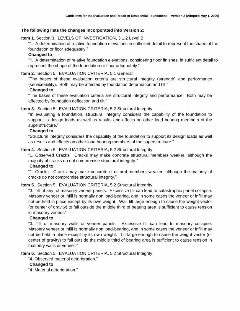
The following lists the changes incorporated into Version 2:
Item 1. Section 3. LEVELS OF INVESTIGATION, 3.1.2 Level B
“1. A determination of relative foundation elevations in sufficient detail to represent the shape of the
foundation or floor adequately.”
Changed to
“1. A determination of relative foundation elevations, considering floor finishes, in sufficient detail to
represent the shape of the foundation or floor adequately.”
Item 2. Section 5. EVALUATION CRITERIA, 5.1 General
“The bases of these evaluation criteria are structural integrity (strength) and performance
(serviceability). Both may be affected by foundation deformation and tilt.”
Changed to
“The bases of these evaluation criteria are structural integrity and performance. Both may be
affected by foundation deflection and tilt.”
Item 3. Section 5. EVALUATION CRITERIA, 5.2 Structural Integrity
“In evaluating a foundation, structural integrity considers the capability of the foundation to
support its design loads as well as results and effects on other load bearing members of the
superstructure.”
Changed to
“Structural integrity considers the capability of the foundation to support its design loads as well
as results and effects on other load bearing members of the superstructure.”
Item 4. Section 5. EVALUATION CRITERIA, 5.2 Structural Integrity
“1. Observed Cracks. Cracks may make concrete structural members weaker, although the
majority of cracks do not compromise structural integrity.”
Changed to
“1. Cracks. Cracks may make concrete structural members weaker, although the majority of
cracks do not compromise structural integrity.”
Item 5. Section 5. EVALUATION CRITERIA, 5.2 Structural Integrity
“3. Tilt, if any, of masonry veneer panels. Excessive tilt can lead to catastrophic panel collapse.
Masonry veneer or infill is normally non load-bearing, and in some cases the veneer or infill may
not be held in place except by its own weight. Wall tilt large enough to cause the weight vector
(or center of gravity) to fall outside the middle third of bearing area is sufficient to cause tension
in masonry veneer.”
Changed to
“3. Tilt of masonry walls or veneer panels. Excessive tilt can lead to masonry collapse.
Masonry veneer or infill is normally non load-bearing, and in some cases the veneer or infill may
not be held in place except by its own weight. Tilt large enough to cause the weight vector (or
center of gravity) to fall outside the middle third of bearing area is sufficient to cause tension in
masonry walls or veneer.”
Item 6. Section 5. EVALUATION CRITERIA, 5.2 Structural Integrity
“4. Observed material deterioration.”
Changed to
“4. Material deterioration.”
Guidelines for the Evaluation and Repair of Residential Foundations – Version 2 (Adopted May 1, 2009)
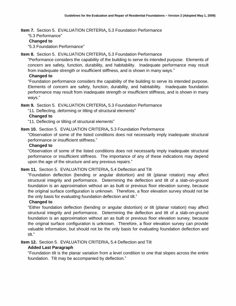
Item 7. Section 5. EVALUATION CRITERIA, 5.3 Foundation Performance
“5.3 Performance”
Changed to
“5.3 Foundation Performance”
Item 8. Section 5. EVALUATION CRITERIA, 5.3 Foundation Performance
“Performance considers the capability of the building to serve its intended purpose. Elements of
concern are safety, function, durability, and habitability. Inadequate performance may result
from inadequate strength or insufficient stiffness, and is shown in many ways.”
Changed to
“Foundation performance considers the capability of the building to serve its intended purpose.
Elements of concern are safety, function, durability, and habitability. Inadequate foundation
performance may result from inadequate strength or insufficient stiffness, and is shown in many
ways.”
Item 9. Section 5. EVALUATION CRITERIA, 5.3 Foundation Performance
“11. Deflecting, deforming or tilting of structural elements”
Changed to
“11. Deflecting or tilting of structural elements”
Item 10. Section 5. EVALUATION CRITERIA, 5.3 Foundation Performance
“Observation of some of the listed conditions does not necessarily imply inadequate structural
performance or insufficient stiffness.”
Changed to
“Observation of some of the listed conditions does not necessarily imply inadequate structural
performance or insufficient stiffness. The importance of any of these indications may depend
upon the age of the structure and any previous repairs.”
Item 11. Section 5. EVALUATION CRITERIA, 5.4 Deflection and Tilt
“Foundation deflection (bending or angular distortion) and tilt (planar rotation) may affect
structural integrity and performance. Determining the deflection and tilt of a slab-on-ground
foundation is an approximation without an as built or previous floor elevation survey, because
the original surface configuration is unknown. Therefore, a floor elevation survey should not be
the only basis for evaluating foundation deflection and tilt.”
Changed to
“Either foundation deflection (bending or angular distortion) or tilt (planar rotation) may affect
structural integrity and performance. Determining the deflection and tilt of a slab-on-ground
foundation is an approximation without an as built or previous floor elevation survey, because
the original surface configuration is unknown. Therefore, a floor elevation survey can provide
valuable information, but should not be the only basis for evaluating foundation deflection and
tilt.”
Item 12. Section 5. EVALUATION CRITERIA, 5.4 Deflection and Tilt
Added Last Paragraph
“Foundation tilt is the planar variation from a level condition to one that slopes across the entire
foundation. Tilt may be accompanied by deflection.”

Guidelines for the Evaluation and Repair of Residential Foundations – Version 2 (Adopted May 1, 2009)
Item 13. Section 5. EVALUATION CRITERIA, 5.5 Overall Deflection
“Overall deflection necessarily involves the overall foundation dimension in a given direction.
When additions have been made to a foundation, the overall foundation dimension should be
considered for each separate foundation element and for the entire foundation. The amount of
overall deflection is measured by the deflection ratio.
Building codes specify that structural members shall be designed to have adequate stiffness to
limit deflections. The International Code Council International Residential CodeTM for One- and
Two-Family Dwellings (IRC) specifies a maximum allowable live load deflection of L/360. This
deflection criterion may be appropriate for the analogous in-service deflection of a residential
foundation due to loading from varying soil conditions. The maximum live load deflection of a
floor is the in-service deflection that typically will not result in excessive damage to cosmetic
finishes.”
Changed to
“Overall deflection necessarily involves the overall foundation dimension in a given direction.
When additions have been made to a foundation, the overall foundation dimension should be
considered for each separate foundation element and for the entire foundation. The amount of
overall deflection is characterized by the deflection ratio.
Building codes specify that structural members shall be designed to have adequate stiffness to
limit deflections. The International Code Council International Residential CodeTM for One- and
Two-Family Dwellings (IRC) specifies a maximum allowable live load deflection of any structural
floor member of L/360, where L is the unsupported length of the member. This requirement
typically is sufficient, in that in-service deflection will not result in excessive damage to cosmetic
finishes, racking of door frames, or vibration. This deflection criterion may be appropriate for the
analogous in-service deflection of a residential foundation, where for simplicity the entire
foundation is considered as though it was a single structural member and differential soil
movement is considered analogous to live load.”
Item 14. Section 5. EVALUATION CRITERIA, 5.7 Tilt
“Floors may tilt enough to affect comfortable or convenient use of the building. A floor slope
greater than 1 percent is usually noticeable. The Americans with Disabilities Act considers a 2
percent slope too large.”
Changed to
“Foundation tilt, deflection, or both may result in floor slopes that affect comfortable or convenient
use of the building. A floor slope greater than 1 percent is usually noticeable. The Americans
with Disabilities Act considers a 2 percent slope too large.”
Guidelines for the Evaluation and Repair of Residential Foundations – Version 2 (Adopted May 1, 2009)
Table of Contents
Section 1. PURPOSE AND SCOPE .......................................................................................... 1
1.1 Introduction ......................................................................................................... 1
1.2 Background ........................................................................................................ 1
1.3 Objectives ........................................................................................................... 1
1.4 Limitation ............................................................................................................ 2
1.5 Adopted Changes ............................................................................................... 2
Section 2. QUALIFICATIONS OF THE ENGINEER .................................................................. 3
2.1 Professional Qualifications ................................................................................. 3
2.2 Professional Ethics ............................................................................................. 3
Section 3. LEVELS OF INVESTIGATION .................................................................................. 4
3.1 General ............................................................................................................... 4
Section 4. EVALUATION METHODOLOGY .............................................................................. 6
4.1 General ............................................................................................................... 6
4.2 Analysis .............................................................................................................. 6
Section 5. EVALUATION CRITERIA ......................................................................................... 7
5.1 General ............................................................................................................... 7
5.2 Structural Integrity .............................................................................................. 7
5.3 Performance ....................................................................................................... 8
5.4 Deflection and Tilt ............................................................................................... 8
5.5 Overall Deflection ............................................................................................... 9
5.6 Localized Deflection ......................................................................................... 10
5.7 Tilt ..................................................................................................................... 10
5.8 Remediation Criteria ......................................................................................... 10
Section 6. REPORTING .......................................................................................................... 11
Section 7. REMEDIAL MEASURES ........................................................................................ 12
7.1 Objectives and Limitations of the Remedial Measures ..................................... 12
7.2 Responsibility of the Engineer .......................................................................... 12
7.3 Non-structural Remedial Measures .................................................................. 12
7.4 Structural Remedial Measures ......................................................................... 14
7.5 Repair of Pier and Beam Foundations .............................................................. 16
7.6 Post Lift Plumbing Testing ................................................................................ 17
7.7 Floor Elevations ................................................................................................ 17
7.8 Compliance Letter ............................................................................................ 17
Guidelines for the Evaluation and Repair of Residential Foundations – Version 2 (Adopted May 1, 2009)
- 1 of 17 -
Guidelines for the
Evaluation and Repair of Residential Foundations
By the Texas Section of the
American Society of Civil Engineers
Section 1. PURPOSE AND SCOPE
1.1 Introduction
The purpose of this document is to provide guidance for engineers practicing in the field
of residential foundation evaluation and repair within the State of Texas with the goal of
protecting the public when obtaining these services. The principal items discussed in this
document are as follows:
1. An introduction presenting the background leading to the need for this document
2. Qualifications of engineers performing evaluations or repair designs
3. Scope of services
4. Methodology
5. Information typically presented in the evaluation report
6. Performance criteria for residential foundations
7. Foundation repair and remedial alternatives
8. Anticipated structure performance after remedial measures
1.2 Background
Texas has large areas with clayey soils that shrink and swell with changes in soil
moisture content. This shrinking and swelling may cause movement of residential
foundations that adversely affects the residence. Other factors may influence foundation
performance. Some of these factors are inadequate design or construction, unanticipated
loads, deterioration of materials, compressibility of the supporting soils, landscaping
practices, leaking plumbing, and slope instability. The American Society of Civil
Engineers, Texas Section (ASCE, TX) developed this document as a guideline for
evaluation and repair of residential foundations. A separate document, Recommended
Practice for the Design of Residential Foundations, also developed by ASCE, TX,
addresses residential foundation design.
1.3 Objectives
The most common purpose of an engineering evaluation of a residential foundation is to
assess its performance. This involves observation and evaluation of cosmetic (non-
structural) distress and structural damage. The evaluation may also provide opinions of
probable causes of distress or damage, assessment of risk of further damage,
Guidelines for the Evaluation and Repair of Residential Foundations – Version 2 (Adopted May 1, 2009)
- 2 of 17 -
recommendations for remedial measures, and cost estimates. If the evaluation
determines that remedial measures are appropriate, the engineer may be asked to
provide the design and construction documents.
1.4 Limitation
These guidelines have been developed by experienced professional engineers and
presents practices they commonly employ to help deal effectively with soil conditions that
historically have created problems for residential foundations in Texas. These guidelines
presume the existence of certain standard conditions when, in fact, the combination of
variables associated with any given project always is unique. Experienced engineering
judgment is required to develop and implement a scope of service best suited to the
variables involved. For that reason, the developers of this document have made an effort
to make the document flexible. Thus, successful application of this document requires
experienced engineering judgment; merely following the guidelines may not achieve a
satisfactory result. Unless adherence to this document is made mandatory through force
of law or by contractual reference, adherence to it shall be deemed voluntary. This
document does not, of itself, comprise the standard of care which engineers are required
to uphold.
1.5 Adopted Changes
The Texas Section of the American Society of Civil Engineers (ASCE) has adopted
procedures for changing the guidelines. In general, those interested in submitting
changes for consideration by the Section should access the website at www.texasce.org,
and follow the instructions for submitting changes. Changes may also be submitted in
writing to the Texas Section-ASCE, 1524 S. IH-35 Suite 180, Austin, TX, 78704, phone
512.472.8905, (please call for faxing instructions). Anonymous changes will not be
considered. Those submitting changes should include contact information, state why a
change is proposed, include applicable calculations if appropriate, and provide alternative
language to incorporate the change. The appropriate committee will consider the
changes, and from time to time the Texas Section may adopt the changes and issue
revised Guidelines.
Guidelines for the Evaluation and Repair of Residential Foundations – Version 2 (Adopted May 1, 2009)
- 3 of 17 -
Section 2. QUALIFICATIONS OF THE ENGINEER
2.1 Professional Qualifications
The evaluation and repair design shall be performed by a professional engineer licensed
in the State of Texas. Engineers in responsible charge of this type of work must be
competent to apply scientific and engineering education, training, knowledge, skill and
experience to the investigation and analysis of constructed facilities. This determines the
cause and extent of diminished performance and the means of remediation. Engineers
should be competent in the related disciplines or should retain outside consultants as
needed.
2.2 Professional Ethics
It is essential to avoid conflicts of interest to maintain the credibility of the evaluation
investigation. The evaluating engineer must demonstrate qualities of character that will
ensure impartiality. These qualities include objectivity, confidentiality, honesty and
integrity.
ASCE members subscribe to the ASCE Code of Ethics, which includes the Fundamental
Principles, Fundamental Canons, and Guidelines to Practice Under the Fundamental
Canons of Ethics. Professional Conduct and Ethics comprise a sub chapter of the Texas
Engineering Practice Act.
Guidelines for the Evaluation and Repair of Residential Foundations – Version 2 (Adopted May 1, 2009)
- 4 of 17 -
Section 3. LEVELS OF INVESTIGATION
3.1 General
The engineer should recommend an appropriate level of investigation to fulfill the
objective of the evaluation. However, the scope of services shall be jointly established
and agreed to by both the client and engineer. The engineer should personally visit the
site and be in responsible charge of the investigative activities. If requested by the client,
the engineer may only provide evaluation of reports by others, but this should be
described as consultation, not investigation. For the purpose of aiding the client in
determining the type of evaluation desired or actually performed, the following three levels
of investigation are offered as guidelines.
3.1.1 Level A
This level of investigation shall be clearly identified as a report of first impressions
and shall not imply that any higher level of investigation has been performed. This
level of investigation will typically include, but is not restricted to:
1. Interview the occupant, owner and client if possible, regarding a history of the
property and performance of the structure
2. Request from the client and review the provided documents regarding the
foundation, such as construction drawings, geotechnical reports, previous
testing and inspection reports, and previous repair information
3. Make visual observations during a physical walk-through
4. Observe factors influencing the performance of the foundation
5. If requested by the client, provide a written report, containing at least the
following:
a. scope of services
b. observations, site characteristics, and data deemed pertinent by the
engineer
c. discussion of major factors influencing foundation performance and
rationale in reaching conclusions concerning the subject residence
d. conclusions and any recommendations for further investigation and
remedial or preventative measures
Guidelines for the Evaluation and Repair of Residential Foundations – Version 2 (Adopted May 1, 2009)
- 5 of 17 -
3.1.2 Level B
This level of investigation should include a written report including the items listed
above for a Level A inspection and also the following items:
1. A determination of relative foundation elevations, considering floor finishes, in
sufficient detail to represent the shape of the foundation or floor adequately.
2. A drawing showing relative elevations
3.1.3 Level C
This level of investigation shall include the items listed above for Level A and Level
B inspections and additional services, testing and related reports deemed
appropriate by the Engineer. These may include, but are not limited to, the
following:
1. Site specific soil sampling and testing
2. Plumbing testing
3. Material testing
4. Steel reinforcing survey
5. Post tensioning cable testing
This level of investigation should also include a more detailed level of reporting,
which may include the following:
1. Scaled drawings
2. Description of factors that affect soil moisture
3. Observations of cut and fill
4. Tree survey
5. Photographs
6. Detailed distress survey
Guidelines for the Evaluation and Repair of Residential Foundations – Version 2 (Adopted May 1, 2009)
- 6 of 17 -
Section 4. EVALUATION METHODOLOGY
4.1 General
A rational method should be used to establish causes of distress or diminished
performance, if any. A suggested method is summarized as follows:
1. Observe the structure, site conditions, other relevant phenomena, and collect pertinent
data
2. Analyze the data
3. Formulate hypotheses
4. Test the hypotheses using analyses acceptable to the engineering profession along
with engineering experience
5. Reach conclusions or reformulate the hypotheses
4.2 Analysis
Diminished performance of a structure may have several causes. The engineer should
approach the analysis with an open mind. The analysis should follow a logical path to its
conclusion. The evaluation should be quantitative to the extent practical, but should not
assume greater accuracy or precision than warranted by the data.

Guidelines for the Evaluation and Repair of Residential Foundations – Version 2 (Adopted May 1, 2009)
- 7 of 17 -
Section 5. EVALUATION CRITERIA
5.1 General
Residential foundations are expected to remain reasonably flat and level to provide
acceptable performance. The criteria herein are intended to lend rationality and
reasonable uniformity, supported by a consensus of practitioners, to the evaluation of
performance and the need for repair of residential foundations.
The bases of these evaluation criteria are structural integrity and performance. Both may
be affected by foundation deflection and tilt. Evaluations may be interpreted from the
body of evidence or demonstrated by calculations.
5.2 Structural Integrity
Structural integrity considers the capability of the foundation to support its design loads as
well as results and effects on other load bearing members of the superstructure.
Elements of concern are stability, component strength and condition, and material
soundness. In evaluating structural integrity, it should be understood that in many
instances portions of the foundation and other structural components may not be
available for observation.
Lack of structural integrity may be indicated by excessive deflection, cracking, partial
collapse, loss of section, material deterioration, or demonstrated by calculations. If loss of
structural integrity is demonstrated by calculations, the conclusion must be consistent with
the physical evidence. Examples of lack of structural integrity include loss of shear
capacity in concrete through excessive cracking, excessive tilt of structural elements such
as posts or piers, unstable conditions in non load-bearing masonry, and rotting of wood
structural members. The engineer should evaluate the following, if they are observed:
1. Cracks. Cracks may make concrete structural members weaker, although the majority
of cracks do not compromise structural integrity.
2. Tilting of posts or piers above grade. Tilting can affect structural integrity or stability,
although posts or piers above grade designed for eccentricity of load can tolerate
some tilting without overstress. However, ordinary construction tolerances may result
in vertical members being built out of plumb.
3. Tilt of masonry walls or veneer panels. Excessive tilt can lead to masonry collapse.
Masonry veneer or infill is normally non load-bearing, and in some cases the veneer or
infill may not be held in place except by its own weight. Tilt large enough to cause the
weight vector (or center of gravity) to fall outside the middle third of bearing area is
sufficient to cause tension in masonry walls or veneer.
Guidelines for the Evaluation and Repair of Residential Foundations – Version 2 (Adopted May 1, 2009)
- 8 of 17 -
4. Material deterioration. The strength of deteriorated material may raise a structural
integrity issue. Evaluation of material deterioration may be based on observation,
material sampling and testing, or non-destructive methods.
5.3 Foundation Performance
Foundation performance considers the capability of the building to serve its intended
purpose. Elements of concern are safety, function, durability, and habitability.
Inadequate foundation performance may result from inadequate strength or insufficient
stiffness, and is shown in many ways. Visible indications may include:
1. Cracking or separating of exterior walls
2. Rotating, buckling, or deflecting masonry veneer panels
3. Cracking of concrete foundation elements
4. Cracking of gypsum board walls and ceilings
5. Separating of walls from ceilings or floors
6. Separating of rafters from a ridge board
7. Racking of door and window frames
8. Separating or racking of other structural framing
9. Cracking, buckling, or separating of floor coverings
10. Separating of initially tight joints
11. Deflecting or tilting of structural elements
12. Deteriorating materials
Observation of some of the listed conditions does not necessarily imply inadequate
structural performance or insufficient stiffness. The importance of any of these indications
may depend upon the age of the structure and any previous repairs.
5.4 Deflection and Tilt
Either foundation deflection (bending or angular distortion) or tilt (planar rotation) may
affect structural integrity and performance. Determining the deflection and tilt of a slab-
on-ground foundation is an approximation without an as built or previous floor elevation
survey, because the original surface configuration is unknown. Therefore, a floor
elevation survey can provide valuable information, but should not be the only basis for
evaluating foundation deflection and tilt.
Deflection may be more difficult to evaluate quantitatively than any other element of
performance. Deflection is characterized by the deflection ratio, which is defined as the
maximum deviation from a straight line between two points divided by the distance (L)
between the two points. Overall deflection, as defined below, may be more easily
interpreted and evaluated than localized deflection. Localized deflection may be a more
common occurrence.
Foundation tilt is the planar variation from a level condition to one that slopes across the
entire foundation. Tilt may be accompanied by deflection.
Guidelines for the Evaluation and Repair of Residential Foundations – Version 2 (Adopted May 1, 2009)
- 9 of 17 -
5.5 Overall Deflection
Overall deflection necessarily involves the overall foundation dimension in a given
direction. When additions have been made to a foundation, the overall foundation
dimension should be considered for each separate foundation element and for the entire
foundation. The amount of overall deflection is characterized by the deflection ratio.
Building codes specify that structural members shall be designed to have adequate
stiffness to limit deflections. The International Code Council International Residential
CodeTM for One- and Two-Family Dwellings (IRC) specifies a maximum allowable live
load deflection of any structural floor member of L/360, where L is the unsupported length
of the member. This requirement typically is sufficient, in that in-service deflection will not
result in excessive damage to cosmetic finishes, racking of door frames, or vibration.
This deflection criterion may be appropriate for the analogous in-service deflection of a
residential foundation, where for simplicity the entire foundation is considered as though it
were a single structural member and differential soil movement is considered analogous
to live load.
A single floor level survey yields the shape of the foundation at one instant, and may or
may not furnish sufficient information to support a conclusion. An evaluation may include
repeated floor level surveys performed over months or years. In such cases, the change
in shape is measured between surveys. In addition, previous foundation repairs may
change elevation shapes.
The engineer evaluating deflection must consider the floor level survey (Levels of
Investigation B or C), and other indications of movement, such as:
1. Brick coursing not level.
2. Poor door alignment.
3. Levelness of built in horizontal surfaces, such as cabinets, countertops, sills and trim.
4. Cracking of exterior and interior wall finishes may indicate deflection, as do most items
listed in 5.3 above.
If a foundation profile indicates the deflection is less than the analogous deflection limit of
L/360, it is unlikely the foundation is deflected materially unless visible indications show
otherwise.
If a foundation profile indicates the deflection is more than the analogous deflection limit
of L/360 and minimal symptoms of deflection are present, then additional information is
needed by the engineer to develop a conclusion. The additional information may allow
the engineer to determine whether or not the foundation has deflected excessively.
If a foundation profile indicates the deflection is more than the analogous deflection limit
of L/360 and sufficient symptoms of deflection are present, then the engineer generally
will be justified in determining that the foundation has deflected excessively.
Guidelines for the Evaluation and Repair of Residential Foundations – Version 2 (Adopted May 1, 2009)
- 10 of 17 -
5.6 Localized Deflection
Localized deflection means a change from original profile or shape in an area smaller
than the overall foundation. Localized deflection manifests itself in similar ways as overall
deflection. It sometimes results in localized structural integrity or performance problems.
The engineer should evaluate the significance of localized deflections and their
consequences as in Section 5.5, but caution is advised when evaluating floor deviations
over only a few feet because built-in unevenness can dominate.
5.7 Tilt
Foundation tilt can affect structural integrity and performance. Tilt of entire foundations
may be evaluated for structural integrity using the criterion stated for veneer panels, as
discussed in Section 5.2 of this document. This criterion may be found in the 1997
Uniform Code for Abatement of Dangerous Buildings.
Foundation tilt, deflection, or both may result in floor slopes that affect comfortable or
convenient use of the building. A floor slope greater than 1 percent is usually noticeable.
The Americans with Disabilities Act considers a 2 percent slope too large.
5.8 Remediation Criteria
If the residence is found to be unsafe due to structural inadequacies, the client and/or civil
authorities should be informed immediately. The engineer should recommend repair,
restoration, remediation, adjustment, or use alternatives if the structural integrity is
inadequate. The engineer should provide alternatives for the client's consideration if
performance is inadequate. Recommendations and alternatives should be
commensurate with the nature and cause of the inadequacy, and the seriousness of its
consequences.
The engineer should consider the cost effectiveness and practicality of the
recommendations, the projected performance, and the needs of the client. For example,
an owner may choose to perform periodic cosmetic repairs and door adjustments, rather
than comprehensive foundation underpinning.
Risks of continued diminished performance are involved in all remedial measures. The
engineer can, however, provide recommendations for remedial measures that reduce
risks. Not implementing the entire remedial plan may increase such risks.
Guidelines for the Evaluation and Repair of Residential Foundations – Version 2 (Adopted May 1, 2009)
- 11 of 17 -
Section 6. REPORTING
The report provides a record of the investigation, analysis and conclusions. Report formats
may vary, but should contain pertinent information that was obtained or generated during the
investigation. The following list includes items that may be included in a report:
1. Authorization and Scope
2. Property Location and Description
3. Sources of Information
4. Data
5. Assumptions
6. Analysis of Information and Data
7. Conclusions
8. Recommendations
9. Limiting Conditions
Guidelines for the Evaluation and Repair of Residential Foundations – Version 2 (Adopted May 1, 2009)
- 12 of 17 -
Section 7. REMEDIAL MEASURES
7.1 Objectives and Limitations of the Remedial Measures
The objective of the engineer should be to design and recommend cost effective remedial
measures. Remedial measures should address diminished structural integrity and
performance identified during the evaluation process. Recommendations for remedial
measures should include a clear description of what the remedial measures are intended
to accomplish.
Perfection is not attainable by remedial measures. Recommendations for remedial
measures should identify important or significant limitations of the measures, and should
comment on reasonable expectations of the remedial measures.
7.2 Responsibility of the Engineer
The engineer who provides sealed remediation documents or plans and specifications
shall be the engineer of record and shall have approval authority over any changes. The
Texas Engineering Practice Act and Rules adopted by the Texas Board of Professional
Engineers prohibits the practice known as “plan stamping” by requiring that engineers
seal only work done by them or under their direct supervision.
7.3 Non-structural Remedial Measures
Non-structural remedial measures may improve foundation performance and reduce
future movement. Applying non-structural remedial measures and monitoring foundation
performance prior to or in lieu of structural repairs may be a prudent approach. Typical
recommendations for non-structural remedial measures may include, but are not limited
to, the measures listed below.
7.3.1 Conscientious Watering Program
The client should be informed that maintaining near uniform soil moisture
conditions near all sides of the foundation may be beneficial. Caution should be
advised against excessive watering.
7.3.2 Vegetation Alteration
Trees or large shrubs near a foundation may cause soil shrinkage under the
foundation. Removal of these trees or shrubs may stop shrinkage or lead to partial
restoration of settled areas of the foundation. Removal may result in upheaval
caused by soil moisture increase, especially if the tree predates construction. If
trees are removed, a suitable waiting period may be recommended to allow for soil
heave.
Guidelines for the Evaluation and Repair of Residential Foundations – Version 2 (Adopted May 1, 2009)
- 13 of 17 -
7.3.3 Root Barriers
Root barriers or periodic root pruning may mitigate the effects of vegetation. Root
barriers are generally not as effective as tree removal.
7.3.4 Gutters and Downspouts
Uncontrolled roof runoff can cause erosion and ponding of water near the
structure, which can be mitigated by addition of gutters and downspouts.
Downspouts should be extended well past the edge of the foundation, past the
edge of abutting planting beds, and into well-drained areas.
7.3.5 Drainage Improvements
Drainage improvements may be appropriate to address foundation movement. If
drainage improvements are considered, the following guidelines may be
appropriate.
7.3.5.1 Surface Grading
Where practicable, for adjacent ground exposed or vegetative areas, a
minimum slope of 5 percent (i.e. 6 inches in 10 feet) away from the
foundation should be provided for the first 5 feet all around. Swales
should have longitudinal slopes of at least 2 percent (i.e. 6 inches in 25
feet), if practicable, and 1 percent (i.e. 3 inches in 25 feet) at a minimum.
7.3.5.2 Erosion Control
The remedial documents should indicate locations where fill, ground cover
or retaining structures are to be added.
7.3.5.3 Surface Water Drainage
When surface drainage cannot be improved adequately by grading, or
when otherwise appropriate, solid pipe drainage systems should be
specified. The ground surface should be graded to slope to one or more
drainage inlets. Cleanouts should be provided for maintenance.
Downspouts may be connected to solid pipe drainage systems, if the pipe
is large enough for the hydraulic load of roof drainage.
7.3.5.4 Subsurface Water Drainage
Subsurface water drains are appropriate to control subsurface water, and
usually consist of perforated pipe, with or without filter fabric, in an
aggregate-filled trench. Provide a continuous minimum slope of 0.5
percent to a surface outfall. Cleanouts should be provided for
Guidelines for the Evaluation and Repair of Residential Foundations – Version 2 (Adopted May 1, 2009)
- 14 of 17 -
maintenance. Downspouts should not be connected to perforated pipe
subsurface drainage systems.
7.3.6 Moisture Barriers
Vertical or horizontal moisture barriers may be effective to mitigate moisture
migration under the foundation. Moisture barriers may consist of durable
impermeable plastic sheeting or other appropriate material attached to the
foundation.
7.4 Structural Remedial Measures
Structural remedial measures may be necessary to improve foundation performance.
7.4.1 Structural Remedial Documents
The engineer should provide documents or plans and specifications that show
specific details of the remedial measures. Plans should be specific for the project,
and be based upon generally accepted engineering practice, including appropriate
engineering calculations.
Remediation documents should include the following:
1. The site address
2. The engineer's name and the firm's name, address, and telephone number
3. The client's name and address
4. The purpose and limitations of the remedial measures
5. Available geotechnical information and source
6. A plan view of the foundation locating known relevant structural components
7. Details to show how to construct repair components
8. Specifications to identify appropriate materials and methods
9. Requirements for construction observation or testing by the engineer or others
10. Existing floor elevations or contours and elevation adjustment requirements, if
appropriate
11. The requirement for performing a floor elevation survey after completion of the
remedial measures
12. Site restoration requirements
Guidelines for the Evaluation and Repair of Residential Foundations – Version 2 (Adopted May 1, 2009)
- 15 of 17 -
7.4.2 Geotechnical Information
The engineer designing structural remedial measures will need geotechnical
information. In some cases, geotechnical information may be derived from
successful local practice, or other experience, verified during construction. For
major or comprehensive remedial measures, geotechnical information should be
derived from a site specific boring and testing program tailored to the project's
needs.
7.4.3 Repair of Slab Foundations
Concrete slab-on-ground foundation repair methods include, but are not limited to:
underpinning, grouting, mudjacking, crack injecting, tendon stressing, and partial
demolition and reconstruction.
7.4.3.1 Underpinning
The plans should show or specify specific locations of underpinning
elements and their sizes, depths, material types, and minimum required
material strengths if appropriate. Underpinning design shall be based
upon generally accepted engineering practice and appropriate engineering
calculations. Performance of underpinning can be compromised by
integrity of existing slab components, changes in soil moisture, skin
friction, point load, and other factors.
Underpinning part of a structure may be specified if calculations, tests, or
experience show that the unsupported structure can support its design
loads. The construction documents should state that underpinning will not
improve the performance of the foundation in non-underpinned areas.
Elevation adjustments by jacking or lifting atop underpinning elements
may be applicable when floor slopes are excessive, or when the design
requires that the foundation be lifted clear of expansive soil. Elevation
adjustments should be governed by field judgment to limit damage to the
foundation and finishes. It is unlikely that elevation adjustments will result
in a level foundation.
7.4.3.2 Grouting and Mudjacking
In general, grouting provides continuous slab support without lifting
appreciably. Mudjacking is done to adjust elevations of a foundation
hydraulically with continuous uniform support. Grouting or mudjacking
may be accomplished with temporary support atop shallow footings or
long-term support atop deep piles or piers. Grouting or mudjacking should
Guidelines for the Evaluation and Repair of Residential Foundations – Version 2 (Adopted May 1, 2009)
- 16 of 17 -
not be performed beneath underpinned foundations if expected swelling of
the soil in the injected area is sufficient to damage the structure.
7.4.3.3 Crack Injecting
Injecting slab cracks of about 1/32 inch and larger with epoxy repair
cement is intended to restore stiffness across the injected crack. If the
objective of the repair is solely to limit moisture intrusion or insect ingress,
then alternative materials, such as sealants, may be appropriate.
7.4.3.4 Tendon Stressing
Stressing relaxed or inadequately stressed post-tensioned tendons may
be applicable when tests show tendon forces below those specified in the
original design or by applicable authority. Stressing may restore the
residual prestress in the concrete, and should be performed after elevation
adjustments and epoxy crack injecting, if any.
7.5 Repair of Pier and Beam Foundations
Pier and beam foundations consist of structurally supported floor systems atop piers,
posts or footings. Repairs may include shimming the floor framing atop the existing
supports, repairing or strengthening the floor framing, replacing or adding supports, and
re-establishing void space.
7.5.1 Floor Shimming
Floor framing may be adjusted by addition of shims atop pier caps. Hardwood or
steel shims may be used to fill gaps.
7.5.2 Framing Repairs
Structural members that are damaged or distressed should be replaced or
reinforced. Treated lumber is recommended for general use in framing repairs.
7.5.3 Additional Supports
Additional supports can be installed when beam or floor framing spans are too
great for the design loads, or when existing supports have deteriorated or are
otherwise ineffective.
7.5.4 Void Space
Void spaces designed under foundation elements should be reestablished as
necessary.
Guidelines for the Evaluation and Repair of Residential Foundations – Version 2 (Adopted May 1, 2009)
- 17 of 17 -
7.5.5 Under-Floor Crawl Space Moisture Control
Under-floor moisture control measures include crawl space cross ventilation,
under-floor drainage, floor beam and floor joist ground clearance, and treated
lumber.
7.6 Post Lift Plumbing Testing
Water supply and sanitary drain lines should be tested for leaks if jacking or lifting is
included in the remedial measures. Gas service lines may require adjustment. Leaks
found by such testing should be repaired.
7.7 Floor Elevations
Floor elevation measurements should be made after implementation of remedial
measures. The engineer should keep a record of these elevation measurements and
furnish a copy to the client.
7.8 Compliance Letter
Upon satisfactory completion of the remedial measures, the engineer, if retained to do so,
should provide a letter of substantial completion to the client stating that to the best of the
engineer's knowledge, the remedial measures generally conform to the remediation
documents, including approved changes. Deviations from the remediation documents
should be noted in the letter.