Embed Size (px)
Citation preview

Guidelines forTraffic Controlin Work Zones
June 2008

Guidelines for Traffic Control in Work Zones
Table of Contents
Introduction ....................................................1
Major Traffic Control Considerations ............2
Fundamental Principles ..................................3
Component Parts of a Temporary Traffic Control Zone ......................................4
Definitions ......................................................5
Tapers .............................................................6
Flagging ................................................... 7-11
Arrow Panels ................................................11
Channelizing Devices ............................ 12-13
Warning Lights .............................................14
Nighttime Operation ....................................14
Signs ....................................................... 15-17
Summary of Layout Dimensions .................17
Typical Application Diagrams ............... 18-48
Flagger’s Checklist ......................................49
Supervisor’s Checklist .................................50
Typical Application Matrix ..........................51

1
Introduction The primary function of temporary traffic control is to
provide for the safe and efficient movement of vehicles, bicyclists, and pedestrians through or around temporary traffic control zones while reasonably protecting workers and equipment. A concurrent objective of the temporary traffic control is the efficient construction and maintenance of the highway.
Part 6 of the Ohio Manual of Uniform Traffic Control Devices (OMUTCD) is Ohio’s standard for all traffic control devices used during construction, maintenance, and utility activities plus incident management. This handbook summarizes some guidelines listed in the OMUTCD. It is directed to state and local government road and street departments, utilities, companies performing construction by permit, and any other entity providing maintenance or construction on a public roadway. It contains basic principles, a description of the standard traffic control devices used in work areas, guidelines for the application of the devices, and typical application diagrams. Also, information concerning proper flagging is presented. This handbook gives the basic principles and provides examples for the design, application, installation, and maintenance of the various types of traffic control devices used in temporary traffic control or for incident management. This information is intended to provide the principles of proper work zone traffic control, but is not a standard. Part 6 of the OMUTCD contains the standards for work zone traffic control.
The application diagrams shown represent minimum requirements for typical situations. They are not intended as substitutes for engineering judgment and should be altered to fit the conditions of a particular site – keeping in mind that all traffic control devices used must be in compliance with Part 6 of the OMUTCD.
To obtain a copy of the current OMUTCD, contact ODOT’s Office of Traffic Engineering (614-466-3601) or Office of Contracts (1-800-459-3778).

2
Major Traffic Control Considerations
Every work zone situation is different so several items must be considered in determining the traffic control needed. Following is a list of some questions that illustrate the major traffic control considerations.
1. What will be the time duration of the work? • Long-term stationary – Work that occupies a location
more than three days. • Intermediate-term stationary – Work that occupies a
location more than one daylight period up to three days, or nighttime work lasting more than one hour.
• Short-term stationary – Daytime work that occupies a location for more than one hour, within a single daylight period.
• Short duration – Work that occupies a location up to one hour.
• Mobile – Work that moves intermit tently or continuously.
2. Where is the work zone located (on the roadway, on the shoulder, or beyond the shoulder)?
3. What type of road is involved?
4. What is the speed of the traffic?
5. What is the traffic volume on the roadway? Should the work be rescheduled to avoid heavy volume conditions?
6. Will the nature of traff ic change while work is underway?
7. Do the local law enforcement agencies need to be notified?
8. What kind of signing will be required?
9. Are cones, drums, barricades, or an arrow panel needed for traffic channelization?
10. Will a flagger be required?

3
Fundamental Principles The control of road users through a temporary traffic control
zone shall be an essential part of highway construction, utility work, maintenance operations, and incident management. The following principles provide guidance to assist road users and help protect workers in the vicinity of temporary traffic control zones.
1. Road user and worker safety in temporary traffic control zones should be an integral and high priority element of every project from planning through design and construction.
2. General plans or guidelines should be developed to provide safety for drivers, bicyclists, pedestrians, workers, enforcement/emergency officials, and equipment.
3. Road user movement should be inhibited as little as practical.
4. Drivers, bicyclists, and pedestrians should be guided in a clear and positive manner while approaching and traversing temporary traffic control zones and incident sites.
5. Routine day and night inspections of temporary traffic control elements should be performed.
6. Attention should be given to the maintenance of roadside safety during the life of the temporary traffic control zone.
7. Each person whose actions affect temporary traffic control zone safety should receive training appropriate to the job decisions each individual is required to make.
8. Good public relations should be maintained.
9. All temporary traffic control devices shall be removed as soon as practical when they are no longer needed.

4
Shoulder Taper
Legend
Direction of travel
Traffic Spaceallows traffic
to pass throughthe activity area
Buffer Space(lateral)provides
protectionfor traffic
and workers
Buffer Space(longitudinal)
provides protection fortraffic and workers
Activity Areais where worktakes place
100 ft.Downstream
Taper
Work Spaceis set aside for
workers, equipment,and material storage
Termination Arealets traffic resumenormal operations
Transition Areamoves traffic outof its normal path
Advance WarningArea
tells traffic what toexpect ahead
Component Parts of a TemporaryTraffic Control Zone

5
Definitions
Rural HighwayA type of roadway normally characterized by lower
volumes, higher speeds, fewer turning conflicts, and less conflicts with pedestrians.
Urban StreetA type of roadway normally characterized by relatively
low speeds, wide ranges of traffic volumes, narrower lanes, frequent intersections and driveways, significant pedestrian traffic, and more businesses and houses.
Other TermsSome terms used commonly in discussing temporary
traffic control applications are not specifically defined in Part 6 of the OMUTCD. Therefore, as part of the traffic control planning process, each agency should review Part 6 (and other appropriate sources, if needed) to determine generally how it will define the terms “low speed”, “high speed”, “low volume”, and “high volume” for streets and highways under its jurisdiction.
For example, page 17 of this handbook includes the OMUTCD table “Suggested Advance Warning Sign Spacing”, which indicates that the speed category (Urban low speed or high speed) is to be determined by the highway agency.
The term “low volume road(s)” is used in the typical applications on pages 27, 29 and 31 of this handbook. Since Part 6 of the OMUTCD does not provide a specific definition of the term, each agency is responsible for addressing how these applications are used, if at all, on its system of streets and highways.

6
Tapers
Merging TaperA merging taper requires the longest distance because
drivers are required to merge into common road space. A merging taper should be long enough to enable merging drivers to have adequate advance warning and sufficient length to adjust their speeds and merge into a single lane before the end of the transition.
Following is a table of merging taper lengths (L) and the maximum spacing of channelizing devices for various speeds and widths of closing.
Taper Length*
Speed Limit
(mph)
Lane Width (Feet) Max. Spacing
of Devices (Feet)10 11 12
25 105 115 125 25
35 205 225 245 35
45 450 495 540 45
55 550 605 660 55
65 650 715 780 65
*Following are the formulas used to calculate taper length:
Posted Speed Formula 40 mph or under L = WS2/60 45 mph or over L = WS
where: L = taper length in feet; W = width of lane or offset in feet; and S = posted speed, or off-peak 85th percentile speed in mph.
Shifting TaperA shifting taper is used when a lateral shift is needed. A
shifting taper should have a length of .5L when posted speed is less than 50 mph and L when posted speed is greater than or equal to 50 mph.

7
Tapers (continued)
Shoulder TaperA shoulder taper may be beneficial on a high-speed
roadway where shoulders are part of the activity area and are closed, or when improved shoulders might be mistaken as a driving lane. Shoulder tapers should have a length of at least 0.33 L.
Downstream TaperA downstream taper should have a minimum length of
approximately 100 feet per lane with devices placed at a spacing of approximately 20 feet.
One-Lane, Two-Way TaperA one-lane, two-way taper is used in advance of an activity
area that occupies part of a two-way roadway in such a way that a portion of the road is used alternately by traffic in each direction. A one-lane, two-way taper should have a maximum length of 100 feet with channelizing devices at approximately 20-foot spacings.
Flagging
FlaggersA flagger shall be a person who provides temporary
traffic control. A flagger should be able to demonstrate the following abilities:
1. Ability to receive and communicate specific instructions.
2. Ability to move and maneuver quickly.
3. Ability to control signaling devices.
4. Ability to understand and apply safe traffic control practices.
5. Ability to recognize dangerous situations and warn coworkers.

8
Flagger UseWhen a one-lane, two-way temporary traffic control zone
is short enough to allow a flagger to see from one end of the zone to the other, traffic may be controlled by either a single flagger or by a flagger at each end of the section.
When a single flagger is used, the flagger should be stationed on the shoulder opposite the constriction or work space, or in a position where good visibility and traffic control can be maintained at all times.
High Visibility ClothingFor daytime and nighttime activity, flagger shall wear
safety apparel meeting requirements of ISEA and labelled as meeting ANSI107-1999 standard performance for Class 2 risk exposure. The apparel background color shall either fluorescent orange-red or fluorescent yellow-green. The reflective material shall be either orange, yellow, white, silver, yellow-green, or fluorescent versions of these colors, and shall be visible at a minimum distance of 1,000 feet. The retroreflective clothing shall be designed to clearly identify the wearer as a person.
Hand-Signaling DevicesThe sign paddle bearing the message STOP or SLOW
provides road users with more positive guidance than flags and should be the primary hand-signaling device.
The STOP/SLOW paddle shall have an octagonal shape on a rigid handle. STOP/SLOW paddles shall be at least 18 inches wide with letters at least 6 inches high and should be fabricated from light semirigid material. The background of the STOP face shall be red with white letters and border. The background of the SLOW face shall be orange with black letters and border. When used at night, the STOP/SLOW paddle shall be retroreflectorized.
Flags, when used, shall be a minimum of 24 inches square, made of a good grade of red material, and securely fastened to a staff that is approximately 36 inches in length.
The free edge of a flag should be weighted so the flag will hang vertically, even in heavy winds. When used at nighttime, flags shall be retroreflectorized red.

9
Flagger StationsFlagger stations shall be located far enough in advance
of the work space so that approaching road users will have sufficient distance to stop before entering the work space.
Guidelines for determining the distance of the flagger station in advance of the work space are shown in the table on page 17. The distances shown may be increased for downgrades and other conditions that affect stopping distance.
Except in emergency, flagger stations shall be preceded by proper advance warning signs. At night, flagger stations shall be illuminated, except in an emergency.
The flagger should stand either on the shoulder adjacent to the road user being controlled or in the closed lane prior to stopping road users. A flagger should only stand in the lane being used by moving road users after road users have stopped. The flagger should be clearly visible to the first approaching road user at all times. The flagger also should be visible to other road users. The flagger should be stationed sufficiently in advance of the workers to warn them (for example, with audible warning devices such as horns, whistles, etc.) of approaching danger by out-of-control vehicles. The flagger should stand alone, never permitting a group of workers to congregate around the flagger station.
At a spot constriction, the flagger may have to take a position on the shoulder opposite the closed section in order to operate effectively. The table on page 17 may be used to determine the visibility distance for road users approaching the flagger.
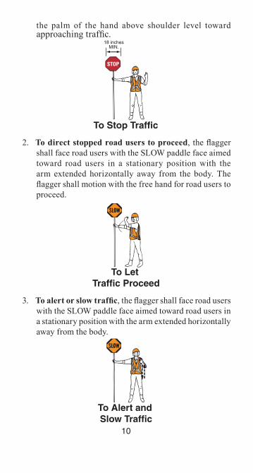
Flagging ProceduresThe following methods of signaling with paddles shall
be used:
1. To stop road users, the flagger shall face road users and aim the STOP paddle face toward road users in a stationary position with the arm extended horizontally away from the body. The free arm shall be held with
10
the palm of the hand above shoulder level toward approaching traffic.
18 inchesMIN.
To Stop Traffic
2. To direct stopped road users to proceed, the flagger shall face road users with the SLOW paddle face aimed toward road users in a stationary position with the arm extended horizontally away from the body. The flagger shall motion with the free hand for road users to proceed.
To Let Traffic Proceed
3. To alert or slow traffic, the flagger shall face road users with the SLOW paddle face aimed toward road users in a stationary position with the arm extended horizontally away from the body.
To Alert and Slow Traffic

11
CommunicationWhen two flaggers are used, they can communicate
verbally or visually if they are close enough and visible to each other. One of the flaggers should be designated as the coordinator. Where the end of a one-lane section is not visible from the other end, the flaggers may maintain control using such methods as:
1. Radio or field telephone,
2. Flag transfer method where the driver of the last vehicle proceeding into the one-lane section is given a red flag (or other token) and instructed to deliver it to the flagger at the other end,
3. An official car that follows the last road user proceeding through the section, or
4. A pilot car to guide a queue of vehicles through the temporary traffic control zone or detour. The flag transfer or official car method should only be used for a maximum length of about one mile. The pilot car shall have a sign mounted on the rear of the vehicle.
Arrow Panels
Flashing arrow panels are effective day and night, for moving traffic out of a lane to the left or right, and may be used for tapered lane closures and moving operations. The minimum size shall be 48” x 24” with at least 12 panel lamps to provide a minimum legibility distance of 1/2 mile. Arrow panels should be equipped with a dimming device capable of 50 percent dimming for use at night along with circular hoods. The only permissible use of an arrow board on a two-lane, two-way street or road is the caution mode.
An arrow panel shall be a sign with a matrix of elements capable of either flashing or sequential displays. This sign shall provide additional warning and directional information

12
to assist in merging and controlling road users through or around a temporary traffic control zone.
An arrow panel should be used in combination with appropriate signs, channelizing devices, or other temporary traffic control devices. An arrow panel should be placed on the shoulder of the roadway or, if practical, further from the traveled lane. It should be delineated with retroreflective temporary traffic control devices, or when within the clear zone, shielded with a barrier or crash cushion. When an arrow panel is not being used, it should be removed; if not removed, it should be shielded; or if the previous two options are not feasible, it should be delineated with retroreflective temporary traffic control devices.
NOTE: Review and understand the full text of Section 6F.56 of the OMUTCD prior to implementing a traffic plan using Arrow Panels.
Channelizing Devices
The function of channelizing devices is to warn road users of conditions created by work activities in or near the roadway and to guide road users.
Channelizing devices should be crashworthy. The spacing of channelizing devices should not exceed a distance in feet equal to 1.0 times the speed limit when used for taper channelization and a distance in feet equal to 2.0 times the speed limit when used for tangent channelization.
Devices that are damaged or have lost a significant amount of their retroreflectivity and effectiveness shall be replaced. See OMUTCD Part 6 for additional information.Channelizing Devices
42 in6 in.2 in.
3 to 4 in.
4 in.
RetroreflectiveBands Retroreflective
Bands
28 in.
CONES4 in. max.6 in.
6 in.2 in.
Night and/or Freeway High-Speed Roadway (≥ 45 mph)

13
Channelizing Devices (continued)NOTE: Warning lights on Channelizing Devices are optional.
28 in.
2 in.
2 in.3 in.
3 in.
2 to 6 in.
3 in.18 in
Day and Low-SpeedRoadway(≤ 40 mph)Night and/or Freeway
High-Speed Roadway( ≥ 45 mph)
TUBULAR MARKERSRetroreflective
Bands RetroreflectiveBand
FacingTraffic
18 in MIN.
36 in.
8 to 12 in.
36 in.MIN.
24 in. MIN. 45º
VERTICAL PANELDRUM
RetroreflectiveBands
3 in.
4 to 6 in.
4 in.
4 in.
TYPE II BARRICADE
45º
** Rail stripe widths shall be 6 in., except that 4 in. wide stripes may be used if rail lengths are less than 36 in.
TYPE I BARRICADE
24 in.MIN.
24 in.MIN.
8 to 12 in. 8 to 12 in.
45º
BARRICADES
36 in.MIN.
5 ft.MIN.
TYPE III BARRICADE
4 ft. MIN.
45º 24 in.
36 in.12 in.
8 in.
DIRECTION INDICATOR BARRICADE
45º
8 to 12 in.

14
Warning Lights
Warning lights shall be mounted on signs or channelizing devices in a manner that, if hit by an errant vehicle, they will not be likely to penetrate the windshield. Flashing warning lights shall not be used for delineation, as a series of flashers fails to identify the desired vehicle path. Warning lights shall have a minimum mounting height of 30 inches to the bottom of the lens.
Type A Low-Intensity flashing warning lights are used to warn road users during nighttime hours that they are approaching or proceeding in a potentially hazardous area. Type A warning lights may be mounted on channelizing devices.
Type B High-Intensity flashing warning lights are used to warn road users during both daylight and nighttime hours that they are approaching a potentially hazardous area. Type B warning lights may be mounted on advance warning signs or on independent supports.
Type C Steady-Burn warning lights may be used during nighttime hours to delineate the edge of the traveled way. When used to delineate a curve, Type C warning lights should only be used on devices on the outside of the curve, and not on the inside of the curve.
Nighttime Operations
All traffic control devices shall be retroreflectorized when used at night. Workers shall wear retroreflectorized vests. Cones shall be equipped with a reflective collar when used at night. When barricades are used, it is desirable to add flashing lights when the barricades are used singly and steady burn lights when they are used in a series for channelization. If a flagger is used, the flagger stations should be adequately illuminated.

15
SignsTypes
1. Regulatory signs inform road users of traffic laws or regulations and indicate the applicability of legal requirements that would not otherwise be apparent. Regulatory signs shall be authorized by the public agency or official having jurisdiction. They are generally rectangular with a black legend and border on a white background. Exceptions include the STOP, YIELD, DO NOT ENTER, WRONG WAY, and ONE WAY signs.
2. Warning signs in temporary traffic control zones notify road users of specific situations or conditions on or adjacent to a roadway that might not otherwise be apparent. Temporary traffic control warning signs shall be diamond-shaped with a black symbol or message and border on an orange background, except for the Highway-Rail Grade Crossing Advance Warning sign and except for signs that are permitted in Part 2 of the OMUTCD to have yellow or fluorescent yellow-green backgrounds.
3. Guide signs provide road users with information to help them along their way through the temporary traffic control zone. The design of guide signs is presented in Part 2 of the OMUTCD. The following guide signs should be used in temporary traffic control zones as needed: standard route markings, directional signs, street name signs, and special guide signs relating to the condition of work being done. If additional guide signs are used in temporary traffic control zones, they shall have a black legend on an orange background.
SizeAdvance warning signs for higher-speed locations shall
have a size of 48 x 48 inches. Where speeds and volumes are moderately low, a minimum size of 36 x 36 inches, may be used for advance warning signs. Deviations from standard sizes shall be in 6-inch increments.

16
Sign SupportsFixed sign supports should be used on long-term projects.
Portable supports are more practical for intermediate and short-term projects. Following are illustrations of height and lateral locations of signs on fixed supports and methods of mounting other than on posts. Signs mounted on barricades or other supports may be at lower heights than on fixed supports but the bottom of the sign shall be no less than one foot above the traveled way.
Sign PlacementSigns should normally be located on the right side of the
roadway. Where special emphasis is needed, signs may be placed on both the left and right sides of the roadway. Signs mounted on barricades and barricade/sign combinations shall be crashworthy. Neither portable nor permanent sign supports should be located on sidewalks, bicycle lanes, or areas designated for pedestrian or bicycle traffic. Signs mounted on portable supports should not be used for a duration of more than 3 days.
URBAN DISTRICTWALKWAY
URBAN DISTRICT
6 to12 ft.
6 to12 ft.
Not lessthan 5 ft.
Not lessthan 6 ft.
Not lessthan 2 ft. Not less
than 2 ft.
Not lessthan 7 ft.
Not lessthan 7 ft.
Not lessthan 4 ft.
Paved ShoulderRURAL DISTRICT WITH
ADVISORY SPEED PLATERURAL DISTRICT
*
*Plaque may be used where needed to indicate maximum recommended speed. Advisory speed should be determined at site by authority in charge of highway or street.

17
Advance Warning AreaThe distance from the first sign to the start of the transition
area should be long enough to give motorists adequate time to respond to the conditions. The tables below summarize layout dimensions as referenced in the typical application diagrams (see pages 18 – 48).
Summary of Layout Dimensions
Suggested Advance Warning Sign Spacing
Road TypeDistance Between Signs (in feet)
A B CUrban (low speed) * 100’ 100’ 100’Urban (high speed) * 350’ 350’ 350’Rural 500’ 500’ 500’Expressway/Freeway 1,000’ 1,500’ 2,640’
* Speed category to be determined by highway agency
Maximum Spacing of Channelizing Devices (in feet)
Road Type Taper Buffer/Work Space DownstreamTwo-lane 20’ 2 x Speed Limit 20’Multi-lane Speed Limit 2 x Speed Limit 20’
Tapers and Flagger Station Distances (in feet)
Speed Limit (mph)
Two-Lane Multi-Lane **
Flagger Station/ Buffer
Max.Two-Way Taper *
Merging Taper
12’ lane
Shifting Taper
12’ lane
Shoulder Taper
10’ shoulder
20 100’ 80’ 40’ 25’ 115’25 100’ 125’ 70’ 35’ 155’30 100’ 180’ 90’ 50’ 200’35 100’ 245’ 130’ 70’ 250’40 100’ 320’ 160’ 90’ 305’45 100’ 540’ 280’ 150’ 360’50 100’ 600’ 600’ 170’ 425’55 100’ 660’ 660’ 190’ 495’60 100’ 720’ 720’ 200’ 570’65 100’ 780’ 780’ 220’ 645’
* Refers to a one-lane, two-way traffic taper (see pages 7 and 26). ** Multi-lane layouts use buffer zones instead of flagger stations Note: Downstream taper = 100 feet

18
Typical Application Diagrams
The diagrams on the following pages represent examples of the application of principles and procedures for safe and efficient temporary traffic control in work zones. The layouts represent minimum requirements. It is not possible to include illustrations to cover every situation which will require work area protection. They are not intended as a substitute for engineering judgment and should be altered to fit the conditions of a particular site. All traffic control devices used must be in compliance with the OMUTCD. Guidelines for taper lengths are given. Refer to pages 6, 7 and 17 for more specific information on taper lengths. For further information, refer to Part 6 of the OMUTCD (using the “TA-” number listed on each layout to identify that illustration in the OMUTCD). A matrix showing setups applicable to typical activities can be found on the back cover of the booklet.
Arrow panel
Arrow panel support or trailer
Channelizing device
Direction of traffic
Flagger
High level warning device (Flag tree)
Sign (shown facing left)
Temporary barrier
Truck mounted attenuator
Type III Barricade
Warning lights
Work space
Work vehicle

19
Work Beyond the Shoulder (TA-1)
A ROAD WORK AHEAD sign should be placed on the left side of the roadway if the work space is located in a median of a divided roadway.
When the work space is behind a barrier, more than 24 inches behind the curb, or 15 feet or more from the edge of any roadway, the ROAD WORK AHEAD sign may be omitted.
Note: For layout dimensions see page 17.

20
1/3 L
A
1/3 L
A
B
1/3 L
A
Work on Shoulder (TA-3)
A SHOULDER WORK sign should be placed on the left side of the roadway for a divided or one-way street only if the left shoulder is affected.
Although vehicle hazard warning signals can be used to supplement the rotating lights or strobe lights, they shall not be used instead of rotating lights or strobe lights.
Note: For layout dimensions see page 17.

21
(optional)
(optional)
Truck-Mounted Attenuator(optional)
Short-Duration or Mobile Operations on Shoulder (TA-4)
Although vehicle hazard warning signals may be used to
supplement the rotating lights or strobe lights, they shall not be used instead of rotating lights or strobe lights. If an arrow panel is used for an operation on the shoulder, the caution mode shall be used.

22
Truck-MountedAttenuator(optional)
A
A
1/3 L
10 ftMIN.
Shoulder Work with Minor Encroachment (TA-6)
All lanes should be a minimum of 10 feet in width as
measured to the near face of the channelizing devices. The treatment shown should be used on a minor road having low speeds. For higher-speed traffic conditions, a lane closure should be used. Although vehicle hazard warning signals can be used to supplement the rotating lights or strobe lights, they shall not be used instead of rotating lights or strobe lights.
Note: For layout dimensions see page 17.

23
500 ft.
1,000 ft.
500 ft.
500 ft.
± 200 ft.
Road Closure with Off-Site Detour (TA-8)
If the road is opened for some distance beyond the intersection and/or there are significant origin/destination points beyond the intersection, the ROAD CLOSED and DETOUR signs on Type III Barricades should be located at the edge of the traveled way.
If the road is closed a short distance beyond the intersection and there are few origin/destination points beyond, the ROAD CLOSED and DETOUR sign may be placed on a Type III Barricade in the center of the roadway.
24
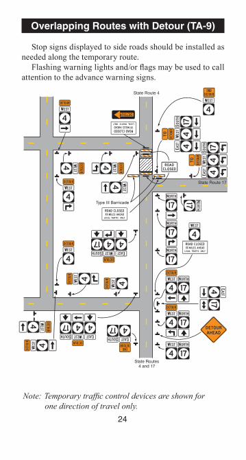
Overlapping Routes with Detour (TA-9) Stop signs displayed to side roads should be installed as
needed along the temporary route. Flashing warning lights and/or flags may be used to call
attention to the advance warning signs.
Note: Temporary traffic control devices are shown for one direction of travel only.
State Route 4
State Routes4 and 17
State Route 17
Type III Barricade

25
Lane Closure on Two-LaneRoad Using Flaggers (TA-10)
For low-volume situations with short work zones on straight roadways where the flagger is visible to road users approaching from both directions, a single flagger, positioned to be visible to road users approaching from both directions, may be used.
The ROAD WORK AHEAD and the END ROAD WORK signs may be omitted for short-duration operations.
Flashing warning lights and/or flags may be used to call attention to the advance warning signs. A BE PREPARED TO STOP sign may be added to the sign series.
Channelizing devices should be extended to a point where they are visible to approaching road users. Floodlights should be provided as needed to mark flagger stations at night. When used, the BE PREPARED TO STOP sign should be located between the advance flagger sign and the ONE LANE ROAD sign.
When a highway-rail grade crossing exists within or upstream of the transition area and it is anticipated that backups resulting from the lane closure might extend through the highway-rail grade crossing, the temporary traffic control zone should be extended so that the transition area precedes the highway-rail grade crossing.
When a highway-rail grade crossing equipped with active warning devices exists within the activity area, provisions should be made for keeping flaggers informed as to the activation status of these warning devices.
When a highway-rail grade crossing exists within the activity area, drivers operating on the left side of the normal centerline should be provided with comparable warning devices as for drivers operating on the right side of the normal centerline.
Early coordination with the railroad company should occur before work starts.
(See IIlustration on Next Page)

26
Lane Closure on Two-LaneRoad Using Flaggers (TA-10)
Note: For layout dimensions see page 17.
100 ft.MAXIMUM
(opt
iona
l)
A
B
C
(optional)
One Lane Two-Way Traffic Taper100 ft. MAXIMUM
A
B
C

27
Lane Closure on Low-VolumeTwo-Lane Road (TA-11)
When flaggers are used, the Flagger symbol sign shall be
used in place of the YIELD AHEAD sign. See Part 6 of the OMUTCD for additional notes.
Note: For layout dimensions see page 17.
(optional)
A
B
C
(optional)
(optional)
(optional)
15 ft.
100 ft. MAX.
Buffer Space (optional)
(optional)
(optional)
(optional)
(optional)
B
C (optional)
100 ft. MAX.
Buffer Space (optional)

28
A
B
C
A
B
C
(optional)
BufferSpace
(optional)
(optional)
BufferSpace
(optional)
Temporary Road Closure (TA-13)
Conditions represented are a planned closure not exceeding 20 minutes during the daytime. The flagger shall follow the procedures noted in “Flagging” beginning on page 7. When used, the BE PREPARED TO STOP sign should be located before the flagger symbol sign.
Note: For layout dimensions see page 17.

29
(optional)
(optional)
10 ft. minimum to edge of pavementor outside edge of
paved shoulder
1/2 L
1/2 L
A
A
Work in Center of Low-Volume Road (TA-15)
The lanes on either side of the center work space should have a minimum width of 10 feet as measured from the near edge of the channelizing devices to the edge of pavement or the outside edge of paved shoulder. Although vehicle hazard warning signals can be used to supplement the rotating lights or strobe lights, they shall not be used instead of rotating lights or strobe lights.
Note: For layout dimensions see page 17.

30
Truck-Mounted Attenuator
Use Sign Shape and Legend appropriate tothe type of work
(optional)
Work Vehicle
Shadow Vehicle
Truck-Mounted Attenuator(optional)
(optional)
Mobile Operations on Two-Lane Road (TA-17)
Vehicle-mounted signs shall be mounted in a manner such that they are not obscured by equipment or supplies. Sign legends shall be covered or turned from view when work is not in progress. Shadow and work vehicles shall display rotating lights or strobe lights. Where practical and when needed, the work and shadow vehicles should pull over periodically to allow motor vehicle traffic to pass. Whenever adequate stopping sight distance exists to the rear, the shadow vehicle should maintain the minimum distance from the work vehicle and proceed at the same speed. The shadow vehicle should slow down in advance of vertical or horizontal curves that restrict sight distance. A truck-mounted attenuator may be used on the shadow vehicle or on work vehicles. The shadow vehicles should also be equipped with two high-intensity flashing lights mounted on the rear, adjacent to the sign.

31
Lane Closure on Minor Street (TA-18)
This temporary traffic control shall be used only for low-volume, low-speed facilities. Where the work space is short, where drivers can see the roadway beyond, and where volume is low, motor vehicle traffic may be self-regulating. Where motor vehicle traffic cannot effectively self-regulate, one or two flaggers shall be used as illustrated on page 26. Flashing warning lights and/or flags may be used to call attention to the advance warning signs. A truck-mounted attenuator may be used on the work vehicle and the shadow vehicle.
Note: For layout dimensions see page 17.
Work Vehicle (optional)
Truck-Mounted Attenuator (optional)
Buffer Space(optional)
100 ft. MAX.
A
A
32
A
B
A
B
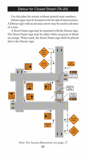
Detour for Closed Street (TA-20)
Use this plan for streets without posted route numbers.Detour signs may be located on the far side of intersections.
A Detour sign with an advance arrow may be used in advance of a turn.
A Street Name sign may be mounted with the Detour sign. The Street Name sign may be either white on green or black on orange. When used, the Street Name sign shall be placed above the Detour sign.
Note: For layout dimensions see page 17.

33
Right Lane Closure on Far Side of Intersection (TA-22)
If the work space extends across the crosswalk, the crosswalk should be closed.
Note: For layout dimensions see page 17.
(optional)
(optional)
(optional)
(optional)
(optional)
A
A
B
A
A

34
Closure in Center of Intersection (TA-26)
A high-level warning device may be placed in the work space, if there is sufficient room. All lanes should be a minimum of 10 feet in width as measured to the near face of the channelizing devices. Although vehicle hazard warning signals can be used to supplement the rotating lights or strobe lights, they shall not be used instead of rotating lights or strobe lights.
Note: For layout dimensions see page 17.
(optional)
1/2 L
A
1/2 L A
1/2 L
A
1/2 LA
10 ft.MIN.
10 ft.MIN.
10 ft.MIN.
10 ft.MIN.

35
Closure at Side of Intersection (TA-27)
The situation depicted can be simplified by closing one or more of the intersection approaches. If this cannot be done, and/or when capacity is a problem, through motor vehicle traffic should be directed to other roads or streets. Depending on road user conditions, flagger(s) or uniformed law enforcement officer(s) should be used to direct road users within the intersection. Although vehicle hazard warning signals can be used to supplement the rotating lights or strobe lights, they shall not be used instead of rotating lights or strobe lights.
Note: For layout dimensions see page 17.
AB
A
B
A
100 ft.MAX.
100 ft.MAX.
100 ft.MAX.
B
(optional)
(optional)
A B

36
Sidewalk Closures and BypassSidewalks (TA-28)
Provisions shall be made for disabled pedestrians.Where high speeds are anticipated, a temporary traffic
barrier and, if necessary, a crash cushion should be used to separate the temporary sidewalks from motor vehicle traffic.
(optional)
SIDEWALK DETOUR SIDEWALK DIVERSION

37
Buffer Space(optional)
Truck-MountedAttenuator(optional)
Buffer Space(optional)
L
A
B
L
A
B
(optional)
(optional)
Interior Lane Closure onMultilane Street (TA-30)
This information applies to low-speed, low-volume
urban streets. Where speed or volume is higher, additional signing such as LEFT LANE CLOSED AHEAD should be used between the signs shown. When a highway-rail grade crossing exists within or upstream of the transition area and it is anticipated that backups resulting from the lane closure might extend through the highway-rail grade crossing, the temporary traffic control zone should be extended so that the transition area precedes the highway-rail grade crossing. Early coordination with the railroad company should occur before work starts.
Note: For layout dimensions see page 17.

38
Lane Closure on DividedHighway (Short Term) (TA-33)
This information also shall be used when work is being performed in the lane adjacent to the median on a divided highway. In this case, the LEFT LANE CLOSED signs and the corresponding LANE ENDS signs shall be substituted. When a side road intersects the highway within the temporary traffic control zone, additional temporary traffic control devices shall be placed as needed.
All vehicles, equipment, workers and their activities should be restricted to one side of the pavement. A truck-mounted attenuator may be used on the work vehicle and/or shadow vehicle.
A ROAD WORK AHEAD sign may be used in place of ROAD WORK XX MILES sign.
(See Illustration on Next Page)

39
Lane Closure on DividedHighway (Short Term) (TA-33)
Note: For layout dimensions see page 17.
SHORT-TERM
500 ft.
Truck-MountedAttenuator(optional)
Buffer space(optional)
Shoulder taper
A
L
B
C

40
Mobile Operation on Multilane Road (TA-35)
Arrow panels shall, as a minimum, be 60 x 30 inches. Vehicles used for these operations should be made highly visible with appropriate equipment, such as: rotating lights, strobe lights, flags, signs, or arrow panels.
Shadow Vehicle 1 should be equipped with an arrow panel and truck-mounted attenuator. Shadow Vehicle 2 should be equipped with an arrow panel. An appropriate lane closure sign should be placed on Shadow Vehicle 2 so as not to obscure the arrow panel. Shadow Vehicle 2 should travel at a varying distance from the work operation so as to provide adequate sight distance for motor vehicle traffic approaching from the rear. The spacing between the work vehicles and the shadow vehicles, and between each shadow vehicle should be minimized to deter road users from driving in between. Work should normally be accomplished during off-peak hours.
When the work vehicle occupies an interior lane (a lane other than the far right or far left) of a directional roadway having a right shoulder 10 feet or more in width, Shadow Vehicle 2 should drive the right shoulder with a sign indicating that work is taking place in the interior lane.
(See Illustration on Next Page)

41
Mobile Operation on Multilane Road (TA-35)
Work Vehicle
Truck-MountedAttenuator(optional)
Truck-MountedAttenuator(optional)
Shadow Vehicle 1
Shadow Vehicle 2
Truck-MountedAttenuator(optional)
42
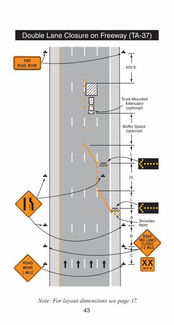
Double Lane Closure on Freeway (TA-37)
The preferred position for the second arrow panel is in the closed exterior lane at the beginning of the second merging taper. If a shadow vehicle is used in the interior lane, if conditions create any confusion as to which lane is closed, or when the first arrow panel is placed in the closed exterior lane at the end of the first merging taper, the second arrow panel should be placed in the interior lane at the end of the second merging taper.
If a paved shoulder of at least 10 feet and sufficient strength is available, the left and adjacent interior lanes may be closed and the right lane and shoulder used to bypass the construction zone. If the shoulder cannot accommodate trucks, trucks may be directed to use the normal travel lanes.
A minimum distance of 2L should be used between the tapers.
(See Illustration on Next Page)
43
Double Lane Closure on Freeway (TA-37)
Note: For layout dimensions see page 17.
Shoulder taper
Truck-MountedAttenuator(optional)
500 ft.
Buffer Space(optional)
L
2L
L
A
B
C

44
Work in Vicinity of Exit Ramp (TA-42)
Guide signs should indicate that a ramp is open and/or where the temporary ramp is located. If the ramp is closed, guide signs need to indicate that it is closed.
If a paved shoulder of at least 10 feet and sufficient strength is available, the left and adjacent interior lanes may be closed and the right lane and shoulder used to bypass the construction zone. If the shoulder cannot accommodate trucks, trucks may be directed to use the normal travel lanes.
Note: For layout dimensions see page 17.
Shouldertaper
(optional)
100 ft.
1,000 ft.1,000 ft.
Temporaryyellow
edge lines L
100 ft.
(optional)
L
A
B
C
L
A
B
C
Temporary white edge lines
Temporarywhite
edge lines
Temporaryyellowedge line
LL

45
Work in Vicinity of Entrance Ramp (TA-44)
An acceleration lane of sufficient length should be provided whenever possible as shown on the left diagram on the following page.
For the information shown on the right diagram of the typical application, where inadequate acceleration distance exists for the temporary entrance, the YIELD sign shall be replaced with STOP signs (one on each side of the approach).
When used, the YIELD or STOP sign should be located so that ramp motor vehicle traffic has adequate sight distance of oncoming mainline vehicle traffic to select a reasonably safe gap in the mainline vehicle flow. Also, a longer acceleration lane should be provided beyond the sign to reduce the gap size needed.
Where STOP signs are used, a temporary stop line should be placed across the ramp at the desired stop location.
(See Illustration on Next Page)

46
Work in Vicinity of Entrance Ramp (TA-44)
Note: For layout dimensions see page 17.
Temporary yellow edge line
Temporary yellow edge line
L
t.f 005
tf.. 005
t.f 005
Temporary white edge line
ShoulderTaper
(optional)A
L
B
C
A
L
B
C

47
Work in Vicinity of Highway-RailGrade Crossing (TA-46)
When highway-rail grade crossings exist either within or in the vicinity of roadway work activities, extra care should be taken to minimize the probability of conditions being created, either by lane restrictions, flagging or other operations, where vehicles might be stopped within the highway-rail grade crossing, considered as being 15 feet on either side of the closest and farthest rail.
If the queuing of vehicles across active rail tracks cannot be avoided, a law enforcement officer or flagger shall be provided at the highway-rail grade crossing to prevent vehicles from stopping within the highway-rail grade crossing (as described above) even if automatic warning devices are in place.
A ROAD WORK AHEAD sign may be used in place of ROAD WORK XXXX FT sign.
(See Illustration on Next Page)

48Note: For layout dimensions see page 17.
Work in Vicinity of Highway-RailGrade Crossing (TA-46)
(optional)
A
B
C
100 ft. MAX.
Extended buffer space
Two-waytraffic taper50 to 100 ft.
A
B
C
(optional)

Flagger’s Checklist
49
1. Before heading to the work zone, make sure you have all necessary equipment in working order including: warning signs, f lagging paddles, retroreflective clothing, and, if needed, communication equipment.
2. Place advance warning sign at the appropriate locations as shown in the table on page 17.• Signs should always be placed in the
following order from farthest from the work zone to closest: ROAD WORK AHEAD, ONE LANE ROAD AHEAD, and the flagger symbol sign.
• Do not begin the flagging operation until all signs are in place.
3. Always stand alone in a highly visible location when f lagging, allowing for space to stop motorists and also warn workers in case of a runaway vehicle.
4. Never stand in the path of traffic.• Flagger may step out near the centerline after
stopping 2-3 vehicles in order to be visible to other approaching vehicles.
5. Do not leave warning signs after the flagging operation has been terminated.

Supervisor’s Checklist
50
1. Follow Part 6 of the OMUTCD. It is Ohio’s standard for work zone traffic control.
2. Have a plan before going to the work site.
3. Remove the devices in a timely manner.
4. Ask yourself, “What is the driver’s view of the work site – at night, during peak hours, etc.?”
5. Ask yourself, “Would I feel safe driving through this work zone?”
6. Investigate crashes/incidents to identify if changes are needed in the traffic control plan.• Take photographs of all traffic control
devices.• Sketch and dimension all devices.
Indicate size of signs, placement from the edge of the travelway, and the height to the bottom of the sign.
The OMUTCD (www.dot.state.oh.us) is the final authority. For all questions contact the ODOT Office of Traffic Engineering at 614-466-3601.

Suggested Traffic Controlfor Work Zone Activities
51
1. The matrix on pages 52-53 shows the suggested Temporary Traffic Control for various work activities.
2. A listing of common work activities is provided along with the Temporary Traffic Control layouts (Typical Applications) that may be considered.
3. No situation will exactly match those provided in the Typical Applications. Use common sense to determine which layout best matches your situation.
4. Recommended method for using the matrix:• Determine the work activity and find it, or
an activity similar to it, in the matrix.• Determine the location of the work activity.
The location of the work affects the type of Typical Application (TA) used.
• Determine duration of the activity. Again, the duration of work affects the type of TA that can be used.
• Review all suggested Typical Applications to see which best fits the operation.
5. Remember!!! The listed Temporary Traffic Controls are merely suggestions.

52
Wo
rk Activities
TA-1
pg. 19TA
-3pg. 20
TA-4
pg. 21TA
-6pg. 22
TA-8
pg. 23 TA
-9pg. 24
TA-10
pg. 26TA
-13pg. 28
TA-17
pg. 30TA
-20pg. 32
Anim
al Clearance
XX
XX
Berm
ingX
X
Bridge R
epairX
XX
X
Chip S
ealO
perationX
XX
Chipping
XX
XX
X
Culvert R
epair/Installation
XX
XX
Ditching
XX
Grader P
atchingX
X
Guardrail
Installation/Repair
XX
X
Suggested Temporary Traffic Control For Work Activities

53
Wo
rk Activities
TA-1
pg. 19TA
-3pg. 20
TA-4
pg. 21TA
-6pg. 22
TA-8
pg. 23 TA
-9pg. 24
TA-10
pg. 26TA
-11pg. 27
TA-17
pg. 30TA
-20pg. 32
Mow
ingX
XX
Pothole P
atchingX
X
Pavem
ent Mark-
ing/ Striping
XX
X
Road C
losingsX
XX
Road G
radingX
XX
Sign Installation/
Repair
XX
Tree Rem
ovalX
XX
TrenchingX
XX
XX
Suggested Temporary Traffic Control For Work Activities

Oh
io D
epartm
ent o
f Transp
ortatio
n
Offi
ce of Traffi
c En
gin
eering
1980 West B
road
St.
Co
lum
bus, O
H 43223
Ph
on
e: 614-466-3601Fax: 614-644-8199
ww
w.d
ot.state.o
h.u
s/traffic