Embed Size (px)
Citation preview
T R A I N I N G C O U R S E S E R I E S 60
Guidelines on Training, Examination and Certification
in Digital Industrial Radiology Testing (RT-D)
V I E N N A , 2 0 1 5
@
I S S N 1 0 1 8 – 5 5 1 8
Guidelines on Training, Exam
ination and Certification in Digital Industrial R
adiology Testing (RT-D
)T
RA
ININ
G C
OU
RS
E S
ER
IES
60
GUIDELINES ON TRAINING, EXAMINATION AND CERTIFICATION
IN DIGITAL INDUSTRIAL RADIOLOGY TESTING (RT-D)

AFGHANISTANALBANIAALGERIAANGOLAARGENTINAARMENIAAUSTRALIAAUSTRIAAZERBAIJANBAHAMASBAHRAINBANGLADESHBELARUSBELGIUMBELIZEBENINBOLIVIA, PLURINATIONAL
STATE OFBOSNIA AND HERZEGOVINABOTSWANABRAZILBRUNEI DARUSSALAMBULGARIABURKINA FASOBURUNDICAMBODIACAMEROONCANADACENTRAL AFRICAN
REPUBLICCHADCHILECHINACOLOMBIACONGOCOSTA RICACÔTE D’IVOIRECROATIACUBACYPRUSCZECH REPUBLICDEMOCRATIC REPUBLIC
OF THE CONGODENMARKDJIBOUTIDOMINICADOMINICAN REPUBLICECUADOREGYPTEL SALVADORERITREAESTONIAETHIOPIAFIJIFINLANDFRANCEGABONGEORGIA
GERMANYGHANAGREECEGUATEMALAGUYANAHAITIHOLY SEEHONDURASHUNGARYICELANDINDIAINDONESIAIRAN, ISLAMIC REPUBLIC OF IRAQIRELANDISRAELITALYJAMAICAJAPANJORDANKAZAKHSTANKENYAKOREA, REPUBLIC OFKUWAITKYRGYZSTANLAO PEOPLE’S DEMOCRATIC
REPUBLICLATVIALEBANONLESOTHOLIBERIALIBYALIECHTENSTEINLITHUANIALUXEMBOURGMADAGASCARMALAWIMALAYSIAMALIMALTAMARSHALL ISLANDSMAURITANIAMAURITIUSMEXICOMONACOMONGOLIAMONTENEGROMOROCCOMOZAMBIQUEMYANMARNAMIBIANEPALNETHERLANDSNEW ZEALANDNICARAGUANIGERNIGERIANORWAY
OMANPAKISTANPALAUPANAMAPAPUA NEW GUINEAPARAGUAYPERUPHILIPPINESPOLANDPORTUGALQATARREPUBLIC OF MOLDOVAROMANIARUSSIAN FEDERATIONRWANDASAN MARINOSAUDI ARABIASENEGALSERBIASEYCHELLESSIERRA LEONESINGAPORESLOVAKIASLOVENIASOUTH AFRICASPAINSRI LANKASUDANSWAZILANDSWEDENSWITZERLANDSYRIAN ARAB REPUBLICTAJIKISTANTHAILANDTHE FORMER YUGOSLAV
REPUBLIC OF MACEDONIATOGOTRINIDAD AND TOBAGOTUNISIATURKEYUGANDAUKRAINEUNITED ARAB EMIRATESUNITED KINGDOM OF
GREAT BRITAIN AND NORTHERN IRELAND
UNITED REPUBLICOF TANZANIA
UNITED STATES OF AMERICAURUGUAYUZBEKISTANVENEZUELA, BOLIVARIAN
REPUBLIC OF VIET NAMYEMENZAMBIAZIMBABWE
The following States are Members of the International Atomic Energy Agency:
The Agency’s Statute was approved on 23 October 1956 by the Conference on the Statute of the IAEA held at United Nations Headquarters, New York; it entered into force on 29 July 1957. The Headquarters of the Agency are situated in Vienna. Its principal objective is “to accelerate and enlarge the contribution of atomic energy to peace, health and prosperity throughout the world’’.
TRAINING COURSE SERIES No. 60
GUIDELINES ON TRAINING, EXAMINATION AND CERTIFICATION
IN DIGITAL INDUSTRIAL RADIOLOGY TESTING (RT-D)
INTERNATIONAL ATOMIC ENERGY AGENCYVIENNA, 2015

COPYRIGHT NOTICE
All IAEA scientific and technical publications are protected by the terms of the Universal Copyright Convention as adopted in 1952 (Berne) and as revised in 1972 (Paris). The copyright has since been extended by the World Intellectual Property Organization (Geneva) to include electronic and virtual intellectual property. Permission to use whole or parts of texts contained in IAEA publications in printed or electronic form must be obtained and is usually subject to royalty agreements. Proposals for non-commercial reproductions and translations are welcomed and considered on a case-by-case basis. Enquiries should be addressed to the IAEA Publishing Section at:
Marketing and Sales Unit, Publishing SectionInternational Atomic Energy AgencyVienna International CentrePO Box 1001400 Vienna, Austriafax: +43 1 2600 29302tel.: +43 1 2600 22417email: [email protected] http://www.iaea.org/books
For further information on this publication, please contact:
Radioisotope Products and Radiation Technology SectionInternational Atomic Energy Agency
Vienna International CentrePO Box 100
1400 Vienna, AustriaEmail: [email protected]
GUIDELINES ON TRAINING, EXAMINATION AND CERTIFICATION IN DIGITAL INDUSTRIAL RADIOLOGY TESTING (RT-D)IAEA, VIENNA, 2015
IAEA-TCS-60ISSN 1018–5518
© IAEA, 2015Printed by the IAEA in Austria
July 2015
FOREWORD
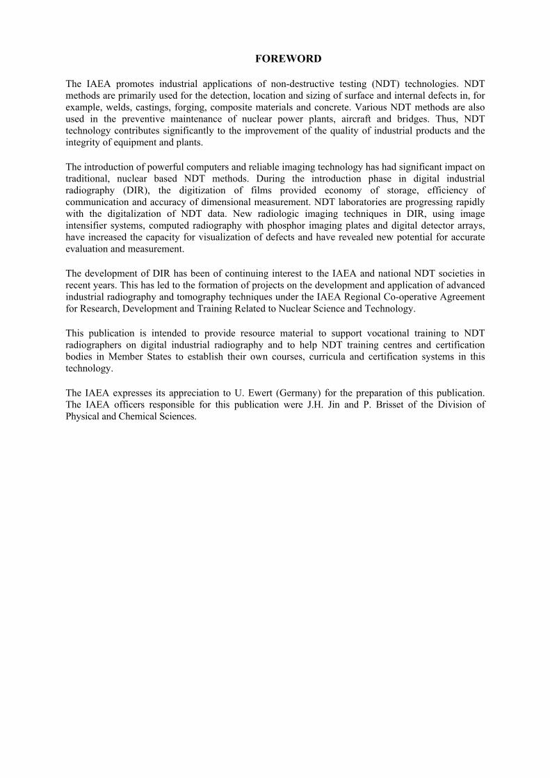
The IAEA promotes industrial applications of non-destructive testing (NDT) technologies. NDT methods are primarily used for the detection, location and sizing of surface and internal defects in, for example, welds, castings, forging, composite materials and concrete. Various NDT methods are also used in the preventive maintenance of nuclear power plants, aircraft and bridges. Thus, NDT technology contributes significantly to the improvement of the quality of industrial products and the integrity of equipment and plants.
The introduction of powerful computers and reliable imaging technology has had significant impact on traditional, nuclear based NDT methods. During the introduction phase in digital industrial radiography (DIR), the digitization of films provided economy of storage, efficiency of communication and accuracy of dimensional measurement. NDT laboratories are progressing rapidly with the digitalization of NDT data. New radiologic imaging techniques in DIR, using image intensifier systems, computed radiography with phosphor imaging plates and digital detector arrays, have increased the capacity for visualization of defects and have revealed new potential for accurate evaluation and measurement.
The development of DIR has been of continuing interest to the IAEA and national NDT societies in recent years. This has led to the formation of projects on the development and application of advanced industrial radiography and tomography techniques under the IAEA Regional Co-operative Agreement for Research, Development and Training Related to Nuclear Science and Technology.
This publication is intended to provide resource material to support vocational training to NDT radiographers on digital industrial radiography and to help NDT training centres and certification bodies in Member States to establish their own courses, curricula and certification systems in this technology.
The IAEA expresses its appreciation to U. Ewert (Germany) for the preparation of this publication. The IAEA officers responsible for this publication were J.H. Jin and P. Brisset of the Division of Physical and Chemical Sciences.

EDITORIAL NOTE
This publication has been prepared from the original material as submitted by the contributors and has not been edited by the editorial staff of the IAEA. The views expressed remain the responsibility of the contributors and do not necessarily reflect those of the IAEA or the governments of its Member States.
Neither the IAEA nor its Member States assume any responsibility for consequences which may arise from the use of this publication. This publication does not address questions of responsibility, legal or otherwise, for acts or omissions on the part of any person.
The use of particular designations of countries or territories does not imply any judgement by the publisher, the IAEA, as to the legal status of such countries or territories, of their authorities and institutions or of the delimitation of their boundaries.
The mention of names of specific companies or products (whether or not indicated as registered) does not imply any intention to infringe proprietary rights, nor should it be construed as an endorsement or recommendation on the part of the IAEA.
The IAEA has no responsibility for the persistence or accuracy of URLs for external or third party Internet web sites referred to in this publication and does not guarantee that any content on such web sites is, or will remain, accurate or appropriate.

CONTENTS
1. INTRODUCTION ......................................................................................................... 1
1.1. SIGNIFICANCE AND USE ............................................................................ 1
2. INTRODUCTION TO DIGITAL INDUSTRIAL RADIOLOGY .................................. 3
2.1. THE METHOD OF RADIOGRAPHIC TESTING (RT) .................................. 3
2.2. LIMITATIONS OF CONVENTIONAL FILM RT METHOD (RT-F) ............. 4
2.3. FILM DIGITIZATION .................................................................................... 4
2.4. DEVELOPMENT OF DIR - DIFFERENCES AND SIMILARITIES BETWEEN DIGITAL RADIOLOGY (RT-D) AND FILM RADIOGRAPHY (RT-F) ................................................................................ 5
2.5. COMPUTED RADIOGRAPHY WITH PHOSPHOR IMAGING PLATES .......................................................................................................... 6
2.6. DIGITAL RADIOLOGY WITH DIGITAL DETECTOR ARRAYS (DDAS) ........................................................................................................... 7
2.7. ADVANTAGES OF DIGITAL RADIOGRAPHIC SYSTEMS ....................... 8
2.8. COMPUTED TOMOGRAPHY (CT) .............................................................. 8
2.9. IMAGE QUALITY IN DIGITAL RADIOLOGY ............................................ 9
3. RT-TECHNIQUES, INDUSTRIAL SECTORS, STANDARDS AND TRAINING HOURS ....................................................................................................................... 19
3.1. RT-D TRAINING MODULES ...................................................................... 19
3.2. DIGITAL TECHNIQUES TO CONSIDER IN RT-D .................................... 19
3.3. PRODUCT SECTORS AND INDUSTRIAL SECTORS ............................... 20
3.4. STANDARDS TO CONSIDER ..................................................................... 21
3.5. REQUIRED TRAINING HOURS ................................................................. 24
4. TRAINING SYLLABI ................................................................................................ 27
4.1. TRAINING CONTENTS FOR DIFFERENT SUBJECTS ............................. 27
4.2. EXAMPLE OF RECOMMENDED PRACTICAL EXERCISES FOR PRACTICAL TRAINING IN RT-D MODULE 2, LEVEL 2 ......................... 33
4.3. TRAINING COMPUTED TOMOGRAPHY ................................................. 40
5. VIRTUAL TRAINING FOR RT-D AND CT .............................................................. 41
6. QUALIFICATION EXAMINATION.......................................................................... 43
6.1. NUMBER OF QUESTIONS FOR GENERAL AND SPECIFIC EXAMINATION ........................................................................................... 43
6.2. PRACTICAL EXAMINATION AND NUMBER OF TEST PIECES ............ 44
6.3. REQUIRED GRADE OF EXAMINATION .................................................. 44
7. CERTIFICATION ....................................................................................................... 47
7.1. EMPLOYERS RESPONSIBILITY AND EXPERIENCE TIMES ................. 47
7.2. VISION REQUIREMENTS .......................................................................... 47

8. SUMMARY AND RECOMMENDATIONS............................................................... 49
9. CONCLUSION ON PRIORITY FOR INTRODUCTION OF RT-D TRAINING MODULES ................................................................................................................. 53
REFERENCES ..................................................................................................................... 55
ABBREVIATIONS .............................................................................................................. 57
1
1. INTRODUCTION
1.1. SIGNIFICANCE AND USE
The need for training in Digital Radiographic Testing (RT-D) came to the attention of the IAEA during an expert meeting in 1996 and the first training courses were conducted in 2000.
The German Society for Non-Destructive Testing NDT, previously, had initiated a training course on digital radioscopy (RT-S) in 1994 (level 1) followed by a level 2 training course in 1996 (~ 520 certificates altogether, 2012).
RT-D training was proposed as a new method in EN 473 in 2008. The proposal was modified later and it was finally decided to split the RT training into RT-F and RT-D (RT-Film and RT-Digital) as two major techniques, instead of having two independent methods. After ISO 9712:2008 [1], with acceptance of EN ISO 9712 in 2012 [2], EN 473 [3] and prEN473 [4] were withdrawn and no further changes were implemented. The amendment, as discussed for EN 473 revision, should be considered for the next revision of ISO 9712 after 2012.
This guideline refers to, and considers differences to the IAEA Training Guideline in Non-Destructive Testing Techniques (TECDOC-628/Rev.2) [5], the ISO 9712:2005 [1], ISO 9712:2012 [2] and EN473:2008 [3].
Since the RT-D training has to cover different digital techniques, the following recommendations were submitted to CEN TC 138 recently:
- Digital Radiographic Testing (RT-D) consists of the following digital techniques:
- Film digitization;
- Image processing;
- Computed radiography with phosphor imaging plates;
- Radiography with digital detector arrays (DDA);
- Radioscopy (also known under real time radiography);
- Computed tomography.
- The classical ‘Radiographic Technique’ is the synonym for film radiographic testing (RT-F)
- Since RT-F has been developed over a period of > 100 years it has been regulated by standards in an excellent manner. The description of Film RT and the quality of radiographs as
well as the evaluation of the films are the basis for national and international contracting in a
variety of industries.
- It can be observed, that the NDT community spends a lot of effort for film replacement by the
digital techniques. The image quality and the procedures for digital RT (RT-D) are significantly different from RT-F. Industries and authorities claim that they do not have the
proof yet, that the Digital Techniques and the evaluations of the digital radiographs are
equivalent to RT-F results due to missing training and standards. Standards for digital radiology have been finalized since 2005 for CR in ASTM and CEN, and for DDA’s in
ASTM in 2010. ASME BPVC Section V considered in 2008 the new major digital RT-D techniques. ISO 17636-2 was published in 2013 for “NDT of welds — Radiographic testing
— Part 2: X and gamma ray techniques with digital detectors”.
- Specialized training is required in RT-D because significant differences between RT-D and
RT-F exist:
- Knowledge in digital image processing is required in RT-D
- Noise sources in RT-D need to be understood
- Contrast to noise ratio (CNR) and signal to noise ratio (SNR) determine the image quality in RT-D instead of density and contrast. This is a significant difference to film
radiography.
- Optimal X-ray energies are different for different RT-D techniques and significantly
different to RT-F
- Most digital detectors have limited sharpness. This requires to be compensated by
better CNR
- RT-D provides more and more accurate measurement tools than RT-F.
- Many RT-D techniques need geometric magnification, which has to be trained.
- New standards are under development to guarantee that RT-D provides the required quality
and the equivalent or better evaluation results (see list of new standards in 5.4). The
application of the new RT-D standards requires more skills than are required for RT-F.
- In certain industrial sectors, e.g. automobile and fine casting industries, NDT personnel does
not need prior RT-F training and RT-F certification, since film will not be used in radioscopic applications using fluoroscopes, intensifiers or DDA’s. RT-D technicians in such industries,
therefore, need training in RT-D only. As such, a full training course is required and
conducted independently of RT-F training.
- Since a basic knowledge on radiography is essential, RT-F certified personnel can be trained
in RT-D with 50% of the required training hours.
- In ISO 9712, RT-D should be also included as a RT technique (see below) since it is
significantly different from RT-F.
- Currently in Germany approx. 1400 NDT-technicians are already certified in accordance to
EN 473 in digital radiology.
This guideline provides recommendations and requirements for the development of a complete training program for the radiographic technique RT-D in three levels. It also considers the different requirements of industrial sectors as, e.g. fine casting inspection under serial production conditions (RT-S training) and film replacement for training of RT-F certified personnel. Finally, three training modules will be defined for RT-D training, which may be selected from training organizations in agreement with the requirements of the national NDT related industries. The training on RT-D is a specialization for professional radiographers.
Radiation safety is a very important aspect of industrial radiography, regardless of the technique used to produce the image (film or digital). It should be part of the training of any radiographer, as stated in TECDOC 628/Rev 2 [5] and ISO9712-2012 [2]. It is therefore not addressed in these Guidelines.
22
3
2. INTRODUCTION TO DIGITAL INDUSTRIAL RADIOLOGY
2.1. THE METHOD OF RADIOGRAPHIC TESTING (RT)
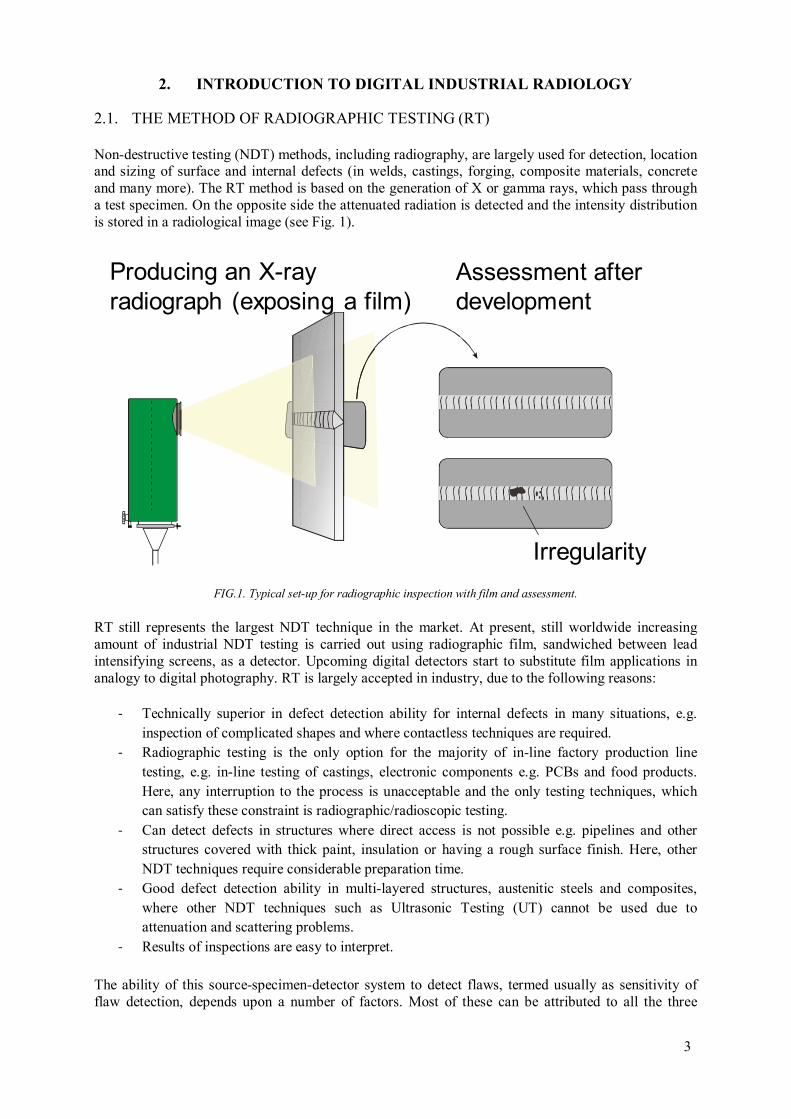
Non-destructive testing (NDT) methods, including radiography, are largely used for detection, location and sizing of surface and internal defects (in welds, castings, forging, composite materials, concrete and many more). The RT method is based on the generation of X or gamma rays, which pass through a test specimen. On the opposite side the attenuated radiation is detected and the intensity distribution is stored in a radiological image (see Fig. 1).
FIG.1. Typical set-up for radiographic inspection with film and assessment.
RT still represents the largest NDT technique in the market. At present, still worldwide increasing amount of industrial NDT testing is carried out using radiographic film, sandwiched between lead intensifying screens, as a detector. Upcoming digital detectors start to substitute film applications in analogy to digital photography. RT is largely accepted in industry, due to the following reasons:
- Technically superior in defect detection ability for internal defects in many situations, e.g.
inspection of complicated shapes and where contactless techniques are required.
- Radiographic testing is the only option for the majority of in-line factory production line
testing, e.g. in-line testing of castings, electronic components e.g. PCBs and food products.
Here, any interruption to the process is unacceptable and the only testing techniques, which can satisfy these constraint is radiographic/radioscopic testing.
- Can detect defects in structures where direct access is not possible e.g. pipelines and other structures covered with thick paint, insulation or having a rough surface finish. Here, other
NDT techniques require considerable preparation time.
- Good defect detection ability in multi-layered structures, austenitic steels and composites,
where other NDT techniques such as Ultrasonic Testing (UT) cannot be used due to attenuation and scattering problems.
- Results of inspections are easy to interpret.
The ability of this source-specimen-detector system to detect flaws, termed usually as sensitivity of flaw detection, depends upon a number of factors. Most of these can be attributed to all the three
Producing an X-ray
radiograph (exposing a film)
Assessment after
development
Irregularity

components of the system, namely, the source, the specimen and the film. These factors can be briefly listed as:
- Type of specimen, its geometry, shape, thickness, physical density, type, location and orientation of defects with respect to the direction of the beam;
- Energy of radiation and source size;
- Scattered radiation, filters if used, source-to-film and specimen-to-film distances;
- Type of detector or film (its definition, contrast and structure noise), processing, viewing conditions, screens;
- Operator’s eye sight, qualification, skill and experience.
Sensitivity is a general term used to describe the ability of a radiograph (digital or analog) to show details in the image. It is a reference to the amount of information or detail in the image. For example, if very small flaws can be seen in the radiograph, it is said to have high or good sensitivity. Radiographic sensitivity depends on image contrast, definition and image noise. Image noise is commonly described as graininess in film radiography.
Practically sensitivity is determined through the use of image quality indicators (IQI) of which there are several kinds. These include the wire type, step wedge type, plate-and-hole type, and step-and-hole type. In the wire type there are two classifications, single wire type and the duplex or wire pair type. The IQI, in principle should be of the same material as the test specimen, except the duplex wire type. It is placed on the surface of the test specimen facing the source and then the exposure is made. The minimum diameter of the wire visible on the radiograph is noted. The sensitivity is then calculated and comes out in percentages, for example, 1%, 2%, 4% etc., the lower the value the better the sensitivity of flaw detection.
2.2. LIMITATIONS OF CONVENTIONAL FILM RT METHOD (RT-F)
Film radiography provides high-resolution images, but it suffers also from several major disadvantages, including:
- low efficiency leads to longer exposure times;
- radiographic films are not reusable;
- requires considerable film developing facilities;
- requires considerable time to develop film and interpret results;
- exposes workers to hazardous chemicals during film development;
- storage and retrieval costs for radiographs after inspection;
- deterioration of X ray film;
- subjectivity in analyzing radiographs
2.3. FILM DIGITIZATION
Film digitization is not a filmless technology, but allows using all means of computer processing also with classical film exposures.
There are several types of film digitization systems such as Point by Point Digitization, Line by Line Digitization and Array Digitization. The most commonly used is the point by point digitization, where the film is moved in front of a collection tube. A laser beam with a fixed diameter passes the film. The diffuse transmitted light through the film is integrated by the collection tube and registered by a photo multiplier (PMT) on top of the collection tube. During the scan the folding mirror moves the laser beam along a horizontal line on the film. The resulting voltage at the photo multiplier is proportional
4
5
to the light intensity behind the film. After amplification a digitization yields grey values that are proportional to the optical density of the film.
Because of a spatial resolution of better than 10 µm and optical density of up to 5 high end digitization yields several new possibilities for conventional radiographic testing. These include, for example, digital film archiving, quantitative evaluation, image processing, automatic image evaluation, remote image transfer and production of reference catalogues for flaw evaluation.
2.4. DEVELOPMENT OF DIR - DIFFERENCES AND SIMILARITIES BETWEEN DIGITAL RADIOLOGY (RT-D) AND FILM RADIOGRAPHY (RT-F)
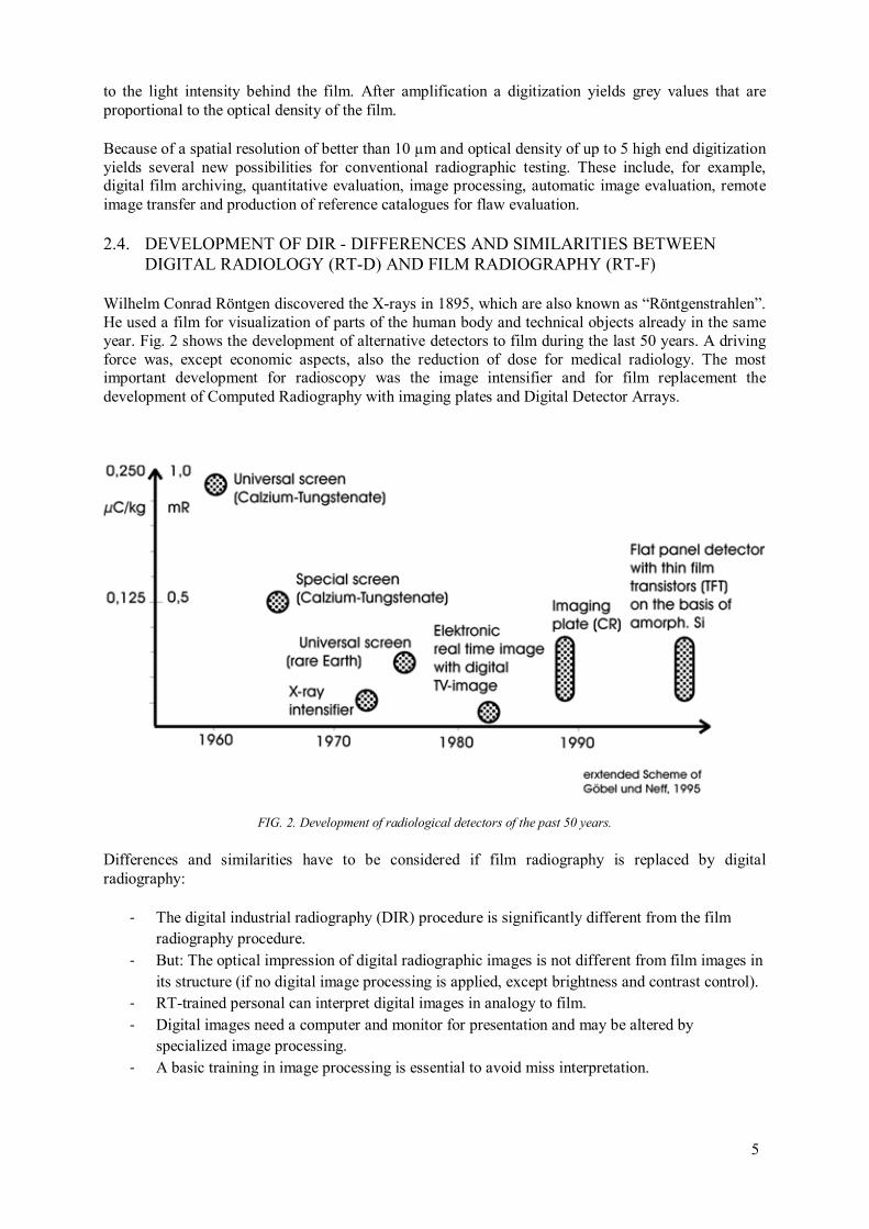
Wilhelm Conrad Röntgen discovered the X-rays in 1895, which are also known as “Röntgenstrahlen”. He used a film for visualization of parts of the human body and technical objects already in the same year. Fig. 2 shows the development of alternative detectors to film during the last 50 years. A driving force was, except economic aspects, also the reduction of dose for medical radiology. The most important development for radioscopy was the image intensifier and for film replacement the development of Computed Radiography with imaging plates and Digital Detector Arrays.
FIG. 2. Development of radiological detectors of the past 50 years.
Differences and similarities have to be considered if film radiography is replaced by digital radiography:
- The digital industrial radiography (DIR) procedure is significantly different from the film radiography procedure.
- But: The optical impression of digital radiographic images is not different from film images in
its structure (if no digital image processing is applied, except brightness and contrast control).
- RT-trained personal can interpret digital images in analogy to film.
- Digital images need a computer and monitor for presentation and may be altered by specialized image processing.
- A basic training in image processing is essential to avoid miss interpretation.

- Quantitative assessment of flaw sizes is improved by digital measuring tools but the results
may differ from those ones of film interpretation.
- New electronic reference catalogues may support correct image assessment.
2.5. COMPUTED RADIOGRAPHY WITH PHOSPHOR IMAGING PLATES
Direct digitising systems accelerate the application of intelligent procedures to facilitate and enhance image interpretation. Since about 10 years imaging plate systems are available for NDT and this can be used as filmless radiography technique, also known as computed radiography (CR) with phosphor imaging plates (IP).
In the 1980s a step forward was made first in medicine by using imaging plates which are able to store the image, eliminating the film and the required processing chemicals and giving birth to Computed Radiography.
FIG. 3. Principle of Computed Radiography with imaging plates and cycle of exposure, scanning and erasure.
An IP consists of a flexible polymer support coated with a sensitive layer. On top it is covered with a thin transparent protective layer. The sensitive layer of most common systems consists of a mixture of BaFBr crystallites doped with Europium and a binder. X-rays or gamma ray quanta result in activation of F-centers in the crystallites, which result in the emission of blue light photons on stimulation with red light photons through a process known as photo stimulated luminescence PSL (see Fig. 3). After X-ray exposure imaging plates have to be scanned by a laser scanner to obtain a digital radiographic image. Finally, the residual information stored in the F-centres can be erased by exposure with bright white light and the IP can be reused up to 1000 times, if carefully handled. Different imaging plate systems are commercially available with different thickness, unsharpness and sensitivity. Guidelines and standards which define the good workmanship criteria for the new digital detectors were development and are again under revision to avoid a loss of information and reduced probability of flaw detection, which may occur by adoption of the medical systems without adaptation to NDT requirements.
Lead
Screen
Exposure of Imaging plate
Imaging
Plate
Cassette
Exposure
Data Acquisition PC
Read out of IP, digitisation
and erasure
Data Output
IP
Lead
Screen
Exposure of Imaging plate
Imaging
Plate
Cassette
Exposure
Data Acquisition PC
Read out of IP, digitisation
and erasure
Data Output
IP
6

7
Imaging plates are used as film replacement, since they provide a similar image quality than film and require a separated exposure for generation of the virtual image. The final generation of the image is performed by a digital laser scanner, which reads the digital radiographic image from the exposed IP.
2.6. DIGITAL RADIOLOGY WITH DIGITAL DETECTOR ARRAYS (DDAS)
The action principle of digital detector arrays is based on the conversion of the incoming X-rays into electrical charges that are electronically readable. In case of the indirect conversion methods, matrices of photo-diodes are employed which are able to convert the radiation (either X-ray or light) into electrical charges. In each photo diode, the charges are integrated over a given time period before they are readout electronically for each single pixel followed by graphic presentation via a suitable data acquisition (see Fig. 4). Each photo diode is linked to an adjacent TFT switch (TFT = thin film transistor – see also laptop displays) that activates the readout process of the accumulated charges at a given time.
The intrinsic photon detection in photo diodes works fine for light photons and X-ray photons up to 20 keV. Above that energy the absorption rate caused by the thin photo diode layer is too low for effective image generation.
For higher X-ray energies the indirect detection is used and is based on a scintillation screen as used in a fluoroscope, but here in direct contact to the photo diode matrix for light detection (see Fig. 4). In this way nearly all light photons leaving the scintillator screen towards the photo diodes are collected by the photo diodes directly touching the screen (see Fig. 5 a). All losses connected with light imaging by a mirror and lens, as used in fluoroscopes, are omitted. As requirement, the photo diode layer should not be degraded by X-ray radiation and the light detection should not be degraded by the penetrating X-ray photons. Because CCD elements are very sensitive to X-rays and cannot be used in direct contact to the scintillator, photo diodes made on CMOS or amorphous Silicon panels are used for light detection.
FIG. 4. Construction scheme of an indirect converting digital detector array.
X-rays (or gamma rays) first strike the scintillation layer, then this layer emits photons in the visible spectrum (see Fig. 5 a). These photons are picked up by the underlying amorphous-Si photo-diode array, which converts them to an electric charge. This charge is then converted into digital grey values for each pixel.
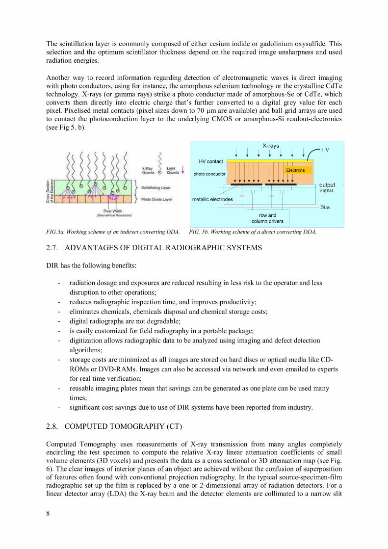
The scintillation layer is commonly composed of either cesium iodide or gadolinium oxysulfide. This selection and the optimum scintillator thickness depend on the required image unsharpness and used radiation energies.
Another way to record information regarding detection of electromagnetic waves is direct imaging with photo conductors, using for instance, the amorphous selenium technology or the crystalline CdTe technology. X-rays (or gamma rays) strike a photo conductor made of amorphous-Se or CdTe, which converts them directly into electric charge that’s further converted to a digital grey value for each pixel. Pixelised metal contacts (pixel sizes down to 70 µm are available) and ball grid arrays are used to contact the photoconduction layer to the underlying CMOS or amorphous-Si readout-electronics (see Fig 5. b).
FIG.5a. Working scheme of an indirect converting DDA. FIG. 5b. Working scheme of a direct converting DDA.
2.7. ADVANTAGES OF DIGITAL RADIOGRAPHIC SYSTEMS
DIR has the following benefits:
- radiation dosage and exposures are reduced resulting in less risk to the operator and less
disruption to other operations;
- reduces radiographic inspection time, and improves productivity;
- eliminates chemicals, chemicals disposal and chemical storage costs;
- digital radiographs are not degradable;
- is easily customized for field radiography in a portable package;
- digitization allows radiographic data to be analyzed using imaging and defect detection
algorithms;
- storage costs are minimized as all images are stored on hard discs or optical media like CD-
ROMs or DVD-RAMs. Images can also be accessed via network and even emailed to experts for real time verification;
- reusable imaging plates mean that savings can be generated as one plate can be used many
times;
- significant cost savings due to use of DIR systems have been reported from industry.
2.8. COMPUTED TOMOGRAPHY (CT)
Computed Tomography uses measurements of X-ray transmission from many angles completely encircling the test specimen to compute the relative X-ray linear attenuation coefficients of small volume elements (3D voxels) and presents the data as a cross sectional or 3D attenuation map (see Fig. 6). The clear images of interior planes of an object are achieved without the confusion of superposition of features often found with conventional projection radiography. In the typical source-specimen-film radiographic set up the film is replaced by a one or 2-dimensional array of radiation detectors. For a linear detector array (LDA) the X-ray beam and the detector elements are collimated to a narrow slit
Röntgenstrahlung+ V
Kontaktfolie
Ausgangs-signal
Bias
Zeilen- / Spalten-ansteuerung
PhotoleiterElektronenElektronen
metallische Elektroden
X-rays
output
row and
column drivers
photo conductor
HV contact
metallic electrodes
Electrons
8

9
and highly aligned to each other to define a slice plane in the specimen. This slit collimation reduces scattered radiation from the inspected object and improves the reconstruction result of this fan-beam CT (important for high X-ray energies with increased X-ray scatter by the inspected object).
Faster inspection times can be realized by using a 2-dimensional image detector (Digital Detector Array) and cone-beam X-ray geometry. In this way a 360° rotation provides projection images of a complete specimen volume. The disadvantage is the missing suppression of scattered radiation generated in the object, which introduces artifacts in the volume reconstruction and reduces the contrast in the projections.
Either the test specimen or the source-detector assembly can be translated and rotated to get views from multiple angles. Especially the 3D Cone-Beam-CT needs computer clusters for image reconstruction of data sets of GBytes per inspected volume.
FIG. 6a. Principle of Computed Tomography. Projections are taken from different angles over 360°. The cross section image is calculated by reconstruction software.
FIG. 6b. Result of a Computed Tomography measurement of a casting with porosities and shrinkage.
2.9. IMAGE QUALITY IN DIGITAL RADIOLOGY
The contrast sensitivity in Digital Industrial Radiology depends on the product of effective attenuation coefficient µeff, also called specific contrast, and the signal-to-noise ratio (SNR), normalized to the basic spatial resolution SRb. This applies for Intesifiers, fluoroscopes, CR, DDAs and X-ray film. Fig. 7 illustrates the effect of noise on flaw detection.
The contrast-to-noise ratio (CNR) per wall thickness difference ∆t (CNRspecific), which is the essential parameter for the visibility of flaws and IQIs of a given size, can be calculated from the detector response (SNR) as a function of exposure dose as follows (small flaws only, see Fig. 7):
CNR/∆t = SNR ⋅ µeff (1)
The perception threshold (PT) for the visibility of a hole (visibility of small details) by the human operator (see Fig. 8) on the image display can be formulated as follows [20-23]:
PT = dvisible ⋅ CNR (2)
PT - perception threshold, constant for typical human operator
Detektor
Röntgen-röhre
Projektions-winkel
Schwächungsprofil
135° Abtastweg
Objekt µ(x,y) x
y
Ι(Φ,ρ)
Φ
90°
45°
ρ
X-ray
tube
Projection
angle
Object µ(x,y)
Detector Scanning
lane
Absorption profile
Detektor
Röntgen-röhre
Projektions-winkel
Schwächungsprofil
135° Abtastweg
Objekt µ(x,y) x
y
Ι(Φ,ρ)
Φ
90°
45°
ρ
X-ray
tube
Projection
angle
Object µ(x,y)
Detector Scanning
lane
Absorption profile
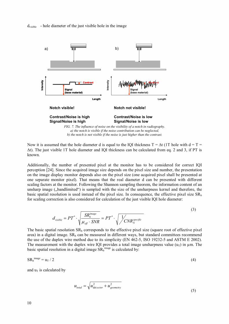
dvisible - hole diameter of the just visible hole in the image
FIG. 7. The influence of noise on the visibility of a notch in radiography.
a) the notch is visible if the noise contribution can be neglected, b) the notch is not visible if the noise is just higher than the contrast.
Now it is assumed that the hole diameter d is equal to the IQI thickness T = ∆t (1T hole with d = T = ∆t). The just visible 1T hole diameter and IQI thickness can be calculated from eq. 2 and 3, if PT is known.
Additionally, the number of presented pixel at the monitor has to be considered for correct IQI perception [24]. Since the acquired image size depends on the pixel size and number, the presentation on the image display monitor depends also on the pixel size (one acquired pixel shall be presented at one separate monitor pixel). That means that the real diameter d can be presented with different scaling factors at the monitor. Following the Shannon sampling theorem, the information content of an unsharp image („bandlimited“) is sampled with the size of the unsharpness kernel and therefore, the basic spatial resolution is used instead of the pixel size. In consequence, the effective pixel size SRb for scaling correction is also considered for calculation of the just visible IQI hole diameter:
(3)
The basic spatial resolution SRb corresponds to the effective pixel size (square root of effective pixel area) in a digital image. SRb can be measured in different ways, but standard committees recommend the use of the duplex wire method due to its simplicity (EN 462-5, ISO 19232-5 and ASTM E 2002). The measurement with the duplex wire IQI provides a total image unsharpness value (uT) in µm. The basic spatial resolution in a digital image SRb
image is calculated by:
SRbimage = uT / 2 (4)
and uT is calculated by
(5)
Length
Inte
ns
ity
Contrast
Signal
(base material)
Length
Inte
ns
ity
Contrast
Signal
(base material)
Length
Inte
nsit
y
Contrast
Signal
(base material)
Notch visible!
Contrast/Noise is high
Signal/Noise is high
Notch not visible!
Contrast/Noise is low
Signal/Noise is low
a) b)
specific
Neff
image
bvisible CNR
PTSNR
SRPTd 1** ⋅=
⋅⋅=µ
22det geometryectortotal uuu +=
10
11
udetector is the inherent unsharpness of the detector and ugeometry is the geometric unsharpness due to the radiographic set up and focal spot size (see ASTM E 1000).
SRb or SRbdetector is considered as basic spatial resolution of the detector (effective detector pixel size,
magnification = 1), measured with the duplex wire IQI directly on the detector (see also ASTM E 2597, E 2445, E 2446). SRb
image is considered here as the basic spatial image resolution, measured with the duplex wire IQI ( ASTM E 2002, EN 462-5) on the source side of the object in the digital image with magnification and unsharpness contributions from the object, which is also a source of scattered radiation.
SRbdetector corresponds typically to the pixel size (pixel limited unsharpness) of direct converting
systems (e.g. α-Se-DDA or CdTe-DDA). It is greater than the pixel size (or laser spot size) for CR and larger than the pixel size (photo diode array elements) of DDA’s with thicker scintillators. The basic spatial resolution parameter is an essential part of EN 14784, ASTM E 2445, E2446 and E 2597.
The term µeff ⋅SNR/SRbimage is considered as normalized specific contrast-to noise ratio (CNRN
specific) per mm thickness difference and normalized by SRb
image (see below for definition of SRbimage). PT’
depends also on operator and viewing conditions. If the hole diameter is much larger than the unsharpness, the equivalent IQI sensitivity (EPS in %) changes for a given material thickness as follows (see ASTM E 746 and E 1025 for 2T sensitivity):
SNRµ
SR
t
PTEPS
eff
image
b
testplate ⋅=
'
(6)
with PT’ ≈ 200, determined from practical trials for clear visibility of holes on a monitor. The calculated EPS (procedure see ASTM E746 and [24]) by eq. (6) is equivalent to the visually measured EPS values as defined by the procedure of ASTM E 746. It is also equivalent to the requirements and definitions of ASTM E 1742 and E 1025.
Since the gray values of the pixels in the digital images (assuming signal is linear to dose) depend on noise and signal intensity independent of the contrast and brightness processing for image viewing, the SNR has been proposed and accepted as an equivalence value to the optical density and a certain film system in film radiography (EN 14784-1,-2 and ASTM E 2445, E2446).
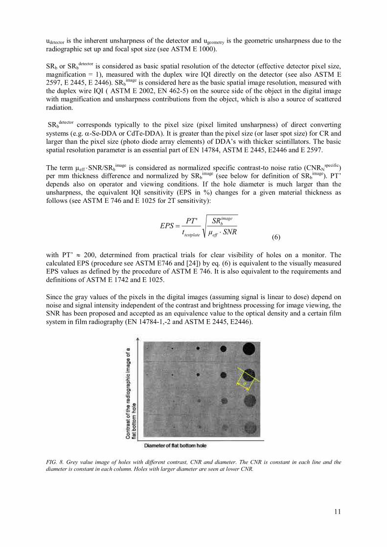
FIG. 8. Grey value image of holes with different contrast, CNR and diameter. The CNR is constant in each line and the
diameter is constant in each column. Holes with larger diameter are seen at lower CNR.
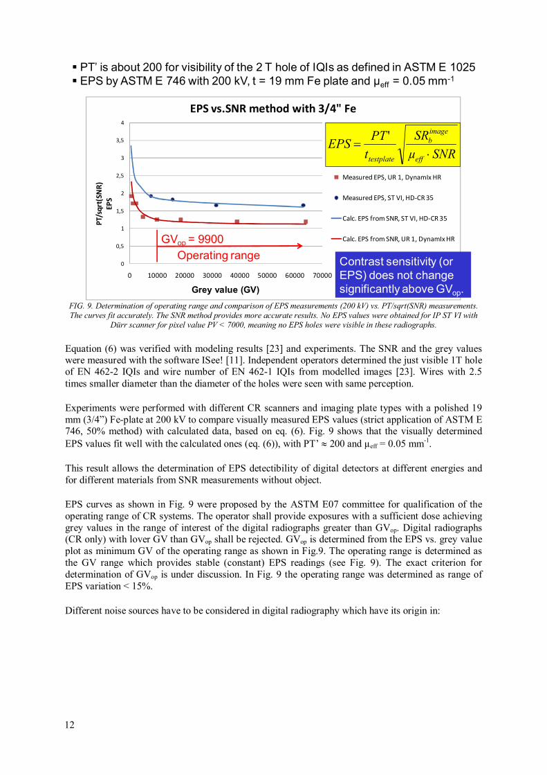
FIG. 9. Determination of operating range and comparison of EPS measurements (200 kV) vs. PT/sqrt(SNR) measurements. The curves fit accurately. The SNR method provides more accurate results. No EPS values were obtained for IP ST VI with
Dürr scanner for pixel value PV < 7000, meaning no EPS holes were visible in these radiographs.
Equation (6) was verified with modeling results [23] and experiments. The SNR and the grey values were measured with the software ISee! [11]. Independent operators determined the just visible 1T hole of EN 462-2 IQIs and wire number of EN 462-1 IQIs from modelled images [23]. Wires with 2.5 times smaller diameter than the diameter of the holes were seen with same perception.
Experiments were performed with different CR scanners and imaging plate types with a polished 19 mm (3/4”) Fe-plate at 200 kV to compare visually measured EPS values (strict application of ASTM E 746, 50% method) with calculated data, based on eq. (6). Fig. 9 shows that the visually determined EPS values fit well with the calculated ones (eq. (6)), with PT’ ≈ 200 and µeff = 0.05 mm-1.
This result allows the determination of EPS detectibility of digital detectors at different energies and for different materials from SNR measurements without object.
EPS curves as shown in Fig. 9 were proposed by the ASTM E07 committee for qualification of the operating range of CR systems. The operator shall provide exposures with a sufficient dose achieving grey values in the range of interest of the digital radiographs greater than GVop. Digital radiographs (CR only) with lover GV than GVop shall be rejected. GVop is determined from the EPS vs. grey value plot as minimum GV of the operating range as shown in Fig.9. The operating range is determined as the GV range which provides stable (constant) EPS readings (see Fig. 9). The exact criterion for determination of GVop is under discussion. In Fig. 9 the operating range was determined as range of EPS variation < 15%.
Different noise sources have to be considered in digital radiography which have its origin in:
0
0,5
1
1,5
2
2,5
3
3,5
4
0 10000 20000 30000 40000 50000 60000 70000
PT/
sqrt
(SN
R)
EP
S
Pixel value
EPS vs.SNR method with 3/4" Fe
Measured EPS, UR 1, DynamIx HR
Measured EPS, ST VI, HD-CR 35
Calc. EPS from SNR, ST VI, HD-CR 35
Calc. EPS from SNR, UR 1, DynamIx HR
SNRµ
SR
t
PTEPS
eff
image
b
testplate ⋅=
'
� PT’ is about 200 for visibility of the 2 T hole of IQIs as defined in ASTM E 1025
� EPS by ASTM E 746 with 200 kV, t = 19 mm Fe plate and µeff = 0.05 mm-1
Operating range
GVop = 9900
Contrast sensitivity (or
EPS) does not change
significantly above GVop.Grey value (GV)
12
13
- EXPOSURE CONDITIONS: Photon noise, depending on exposure dose (e.g. mA⋅s or
GBq⋅min). This is the main factor! SNR increases with higher exposure dose.
- Limitation for the maximum achievable SNR:
- DETECTOR: Structural noise of DDAs and Imaging Plates also called fixed
pattern noise (due to variations in pixel to pixel response and inhomogeneities in the phosphor layer).
- OBJECT:
- Crystalline structure of material (e.g. nickel based steel, mottling)
- Surface roughness of test object
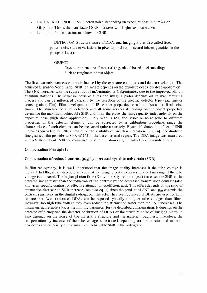
The first two noise sources can be influenced by the exposure conditions and detector selection. The achieved Signal-to-Noise Ratio (SNR) of images depends on the exposure dose (low dose application). The SNR increases with the square root of mA·minutes or GBq·minutes, due to the improved photon quantum statistics. The structure noise of films and imaging plates depends on its manufacturing process and can be influenced basically by the selection of the specific detector type (e.g. fine or coarse grained film). Film development and IP scanner properties contribute also to the final noise figure. The structure noise of detectors and all noise sources depending on the object properties determine the maximum achievable SNR and limit, therefore, the image quality independently on the exposure dose (high dose application). Only with DDAs, the structure noise (due to different properties of the detector elements) can be corrected by a calibration procedure, since the characteristic of each element can be measured quite accurately. Figure 10 shows the effect of SNR increase (equivalent to CNR increase) on the visibility of fine flaw indications [13, 14]. The digitized fine grained film provides a SNR of 265 in the base material region. The DDA image was measured with a SNR of about 1500 and magnification of 3.5. It shows significantly finer flaw indications.
Compensation Principle I:
Compensation of reduced contrast (µeff) by increased signal-to-noise ratio (SNR)
In film radiography, it is well understood that the image quality increases if the tube voltage is reduced. In DIR, it can also be observed that the image quality increases in a certain range if the tube voltage is increased. The higher photon flow (X-ray intensity behind object) increases the SNR in the detected image faster than the reduction of the contrast by the decreased transmission contrast (also known as specific contrast or effective attenuation coefficient µeff). This effect depends on the ratio of attenuation decrease to SNR increase (see also eq. 1) since the product of SNR and µeff controls the contrast sensitivity in the digital radiograph. The effect has been observed if DDAs are used for film replacement. Well calibrated DDAs can be exposed typically at higher tube voltages than films. However, too high tube voltage may even reduce the attenuation faster than the SNR increases. The maximum achievable SNR is the limiting parameter for the described compensation. It depends on the detector efficiency and the detector calibration of DDAs or the structure noise of imaging plates. It also depends on the noise of the material’s structure and the material roughness. Therefore, the compensation by increase of the tube voltage is restricted depending on the detector and material properties and especially on the maximum achievable SNR in the radiograph.
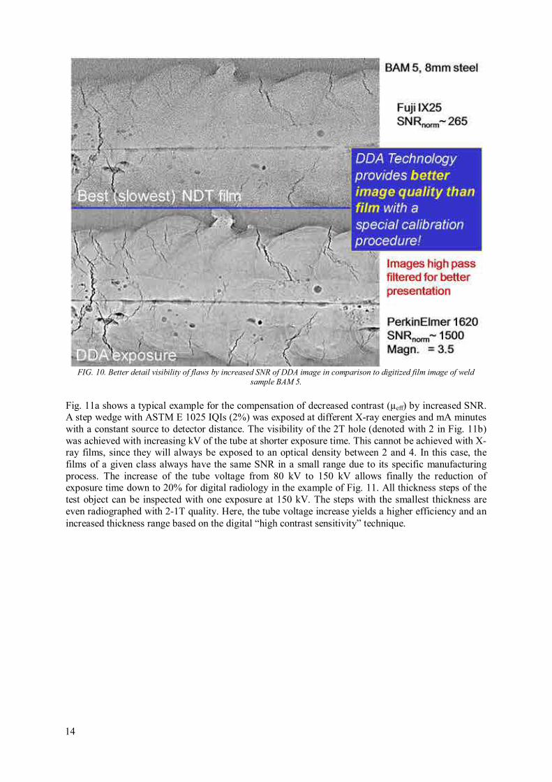
FIG. 10. Better detail visibility of flaws by increased SNR of DDA image in comparison to digitized film image of weld
sample BAM 5.
Fig. 11a shows a typical example for the compensation of decreased contrast (µeff) by increased SNR. A step wedge with ASTM E 1025 IQIs (2%) was exposed at different X-ray energies and mA minutes with a constant source to detector distance. The visibility of the 2T hole (denoted with 2 in Fig. 11b) was achieved with increasing kV of the tube at shorter exposure time. This cannot be achieved with X-ray films, since they will always be exposed to an optical density between 2 and 4. In this case, the films of a given class always have the same SNR in a small range due to its specific manufacturing process. The increase of the tube voltage from 80 kV to 150 kV allows finally the reduction of exposure time down to 20% for digital radiology in the example of Fig. 11. All thickness steps of the test object can be inspected with one exposure at 150 kV. The steps with the smallest thickness are even radiographed with 2-1T quality. Here, the tube voltage increase yields a higher efficiency and an increased thickness range based on the digital “high contrast sensitivity” technique.
14
15
FIG. 11a. Step wedge of steel with ASTM E 1025 IQIs for determination of image quality.
FIG. 11b. Achieved IQI quality (smallest visible hole of 2% IQI. It means: 1: 1T hole, 2: 2T hole, 4: 4T hole) as function of kV, mAmin and wall thickness in inch for test object of
Fig. 11 a.
As consequence the requirements for film radiography in relation to the maximum tube voltage (EN 1435, EN 444, ISO 17636:2003) are not valid anymore for digital radiography. It is proposed for CD ISO 17636-2 to modify as follows:
• To maintain good flaw sensitivity, the X-ray tube voltage should be as low as possible. The
recommended maximum values of tube voltage versus thickness are given in Fig. 20 of ISO
17636-2:2013.
• These maximum values are best practice values for film radiography.
• DDAs provide sufficient image quality at significant higher voltages too.
• Highly sensitive imaging plates with high structure noise of plate crystals (coarse grained)
should be applied with about 20 % less X-ray energy as indicated in Fig. 20 of ISO 17636-
2:2013.
• High definition imaging plates, which are exposed similar to X-ray films and having low
structure noise (fine grained) can be exposed with X-ray energies of Fig. 12 (from ISO 17636-
2:2013) or significantly higher if the SNR is sufficiently increased.

FIG. 12. Selection of Exposure Voltage of X-ray Tube becomes a Recommendation for Digital Detectors (see ISO 17636-1
and -2 for X Ray devices up to 1 000 kV as a function of penetrated thickness and material).
Compensation Principle II:
Compensation of insufficient detector sharpness (higher unsharpness) by increased SNR.
The European standard EN 14784-2 requires the application of high definition CR systems for X-ray inspection with pixel sizes of less than 50µm for class B inspection (for wall thickness <12 mm and tube voltages <150 kV). Most available systems do not allow a resolution below 50µm pixel size and are excluded for industrial X-ray applications at thin wall thicknesses in Europe. Recent trials have shown that DDAs provide a better image quality and IQI visibility than industrial X-ray films [13, 14]. In a high contrast sensitivity mode the DDAs achieve better IQI reading than film exposures. This effect is observed when subpixel contrast resolution is achieved. This is the case, if the SNR at the detector is increased considerably. If a wire or crack is smaller than a pixel, it still influences the contrast and can be seen in the image if the contrast is sufficiently higher than the noise. Therefore, systems with insufficient spatial resolution can be applied if their higher unsharpness is compensated by increased SNR.
Fig. 13 shows the copy of revised table for hardware selection of CD ISO 17636-1 (class B) which is widely conforming to the ISO 10893-7:2010. No DDA or CR system shall be used, which does not provide the required basic spatial resolution, as defined in Tables B.13, B. 14 of CD ISO 17636-2. If the available digital system has not sufficient spatial resolution, it may be used on basis of the compensation (II) principle.
16

17
FIG. 13. Reproduction of table B.14 of ISO 17636-2:2013: Minimum requirements of digital detection systems for class B
testing as function of wall thickness.
It is proposed to permit the application of unsharp systems, if the visibility of the required wire or step hole IQI is increased by compensation of missing duplex wire resolution (caused by too high basic spatial resolution values of the detection system) through SNR enhancement (see EN 462-5, ASTM E 2002 and requirements of EN 14784-2). Several new standards define minimum duplex wire values for specific applications (e.g. ISO 10893-7 or ISO 17636-2:2013). Typically, one higher (smaller diameter, see EN 462-1) single wire (resulting in higher contrast sensitivity) shall be seen through adjustment of parameters that increase the SNR if an additional duplex wire of spatial resolution is required in the system qualification for a given material thickness and application. It was proposed in CEN TC 138 WG 1 that the compensation should allow maximum 2 wire vs. wire pair compensations. The compensation should also be applicable to plate hole IQIs too. This is still under discussion.
Example: Is a digital detection system used (DDA or SR), which achieves the duplex wire pair D11 (first unsharp wire pair) for inspection of a 5 mm thick object and class B testing as defined in ISO 17636-2:2013 (required is D12 and W16), single wire W17 shall be clearly visible in the image for acceptable quality.
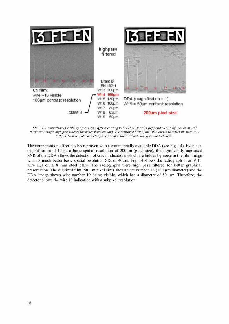
FIG. 14. Comparison of visibility of wire type IQIs according to EN 462-1 for film (left) and DDA (right) at 8mm wall thickness (images high pass filtered for better visualization). The improved SNR of the DDA allows to detect the wire W19
(50 µm diameter) at a detector pixel size of 200µm without magnification technique!
The compensation effect has been proven with a commercially available DDA (see Fig. 14). Even at a magnification of 1 and a basic spatial resolution of 200µm (pixel size), the significantly increased SNR of the DDA allows the detection of crack indications which are hidden by noise in the film image with its much better basic spatial resolution SRb of 40µm. Fig. 14 shows the radiograph of an # 13 wire IQI on a 8 mm steel plate. The radiographs were high pass filtered for better graphical presentation. The digitized film (50 µm pixel size) shows wire number 16 (100 µm diameter) and the DDA image shows wire number 19 being visible, which has a diameter of 50 µm. Therefore, the detector shows the wire 19 indication with a subpixel resolution.
18
19
3. RT-TECHNIQUES, INDUSTRIAL SECTORS, STANDARDS AND TRAINING
HOURS
3.1. RT-D TRAINING MODULES
It is proposed to subdivide the RT method in the following 2 techniques:
- Film Radiography (RT-F)
- Digital Industrial Radiology (RT-D)
Three training MODULEs are proposed and described in detail for the RT-D training in this guideline:
- RT-D Module 1: Training module for personnel having no RT knowledge, and entering the
RT-D training course without training and certification in film radiography (RT-F).
NOTE: Computed Tomography (RT-CT) is a very specialized technique and is considered as part of the RT-D training here. No special training course for RT-CT is proposed yet.
- RT-D Module 2: Training module for RT-F certified personnel. At minimum 50% of the RT-
D training hours is required. This is considered as “Film replacement course”.
NOTE: The RT-D Module 2for RT-F, level 2 (or 3), certified personnel allows direct access to RT-D, level 2, without level 1 training and certification if a minimum 50% of the RT-D, level 1+2, training hours have been achieved. This is considered as “Film replacement course” for direct access to RT-D, level 2, without level 1 training and certification.
- RT-S: specialized training module for personnel having no knowledge on and certification in
RT-F, but shall be trained for NDT with analogue and digital radioscopic devices for
automated and semi-automated testing of castings and welds. Between 50% and 100% of the RT-D training hours are required. This training course is designed for personnel, which is
operating stationary RT-S equipment for serial production of castings (e.g. car industry) and welding (e.g. pipe manufacturing industry).
3.2. DIGITAL TECHNIQUES TO CONSIDER IN RT-D
The digital industrial Radiology (RT-D) shall consider the following digital techniques:
- Film Digitization
- Image processing
• Basics
• Contrast and brightness (point operations)
• Digital Filter
• Measurement of dimensions
• Semi-automated defect recognition
- Computed Radiography
• Film replacement
- Radiography with DDAs
• Film replacement
• High contrast sensitivity technique

- Radioscopy (RT-S: real time and digital)
• Image intensifier
• Fluoroscopy
• Automated and semi-automated defect recognition
- Computed Tomography (RT-CT)
Training and exercises have to be conducted in all RT-D techniques except that the certification is restricted to selected techniques only. The training of a restricted number of techniques can be performed in a shorter training time but the training shall be performed in at least 50% of the training hours of the RT-D training course, Module 1. The development of a written instruction/procedure has to be an essential part of training for all techniques in level 2 and 3. The training contents for the different modules are described in more detail in the syllabi in Tables 5-7, see also Annex III.
3.3. PRODUCT SECTORS AND INDUSTRIAL SECTORS
The following product sectors should be considered by the Certification Board:
- Welded products (w)
• Pipes and plates
• Boilers
• Production and in-service testing
- Castings (c)
• Castings with “radiography” like inspection (film replacement)
• Multi angle inspection, dynamic testing
• Serial inspection of castings without and with automated defect recognition (ADR)
- Tubes and Pipes (t)
• Corrosion and erosion evaluation
• Wall thickness measurements in tangential and double wall technique
- Others
• Turbine blades, forge products, plastics, composites, ceramics, electronics, food,
concrete
For radiographic testing (RT) the industrial sector pre and in-service testing combines the product sectors w, c and t.
All RT-D training modules should consider at least the three product sectors: Welded products (w), castings (c) and tubes and pipes (t). This should be certified under product sectors “Welds, Castings and tubes and pipes” in reference to ISO 9712:2005 or under industrial sector “Pre and in-service testing” in reference to ISO 9712:2012.
The training of a reduced number of product sectors may be performed in a shorter training time, but the training shall be performed in at least 50% of the training hours of the complete RT-D training course, Module 1 (follow specific requirements in ISO 9712:2012).
The development of a written instruction (level 2) or a written procedure (level 3) has to be trained for all techniques. The training contents for the different modules and sectors are described in more detail in the syllabi in Tables 5-7.
20

21
3.4. STANDARDS TO CONSIDER
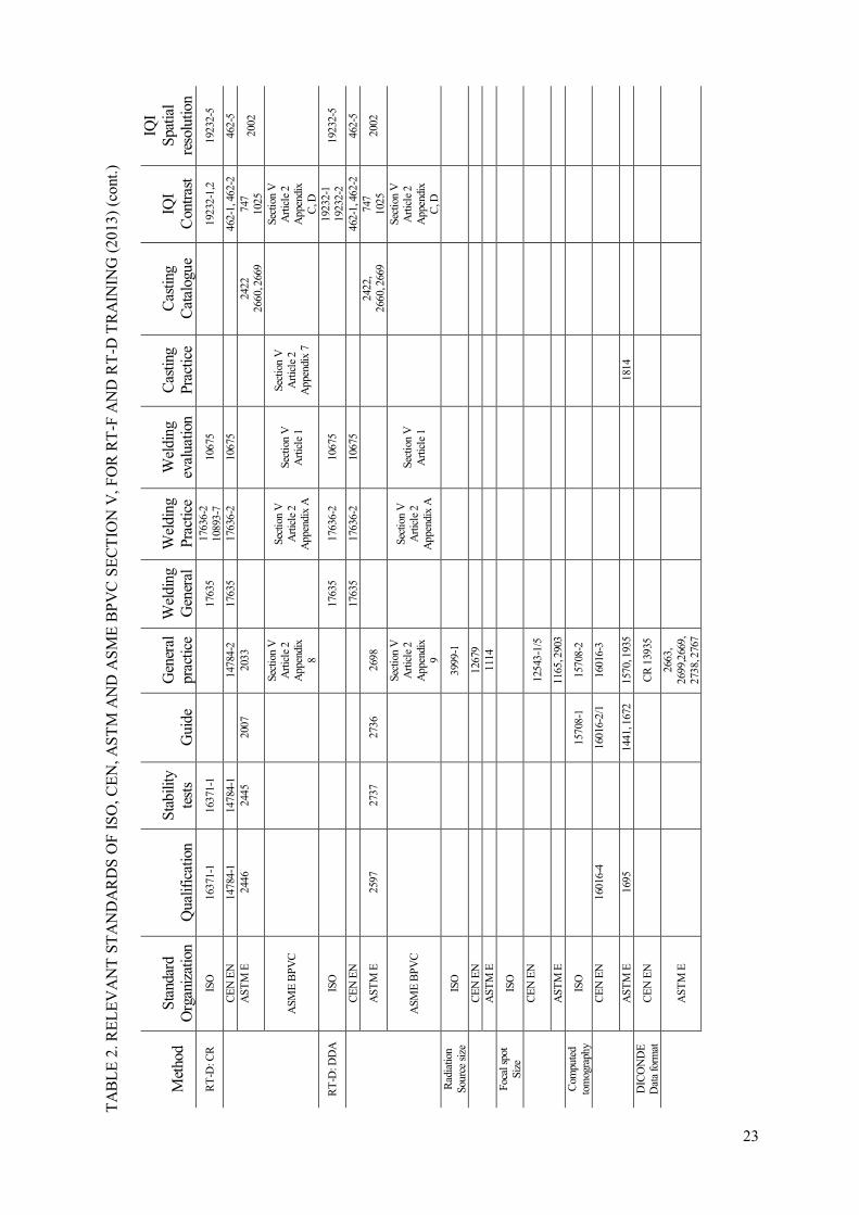
Table 1 show the latest developments in standardization, which have to be included in the RT-D training. Table 2 shows all relevant standards (as available until 2011) which should be considered in RT-F and RT-D training of level 2 and 3.
TABLE 1. OVERVIEW OF STANDARDS ON DIGITAL INDUSTRIAL RADIOLOGY (09/2013)
Standard Topic
EN 13068 Radioscopy
EN 14096, ISO 14096 Film Digitisation
EN 14784 CR (2005) becomes ISO 16371
Part 1: Classification of Systems, Part 2: General principles
ISO 10893-7 (2010)
Steel tubes – NDT of welds with DDA and (CR)
ISO 17636-2 (2013)
NDT of welds: CR and DDA, to substitute EN 1435
EN 16407: corrosion and wall
thickness measurement
Practice with film, CR and DDA for double wall RT and
tangential RT
ASME (BPVC, S.V)
Radiography with film, CR, DDA and more
ASTM CR (2005) Under revision
Classification (E 2446-05), Long term stability (E2445-05), Guide (E 2007-10), Practice (E 2033-06)
ASTM DDA (2010) Characterisation (E 2597-07), Long Term Stability (E
2737-10), Guide (E 2736-10), Practice (E 2698-10)
ASTM DICONDE (2010) (data format)
Standard Practice for Digital Imaging and
Communication Non destructive Evaluation (DICONDE) (E 2663-08, E 2699-10, E 2669-10, E 2738-10, E 2767-
10)
ASTM Digital reference image catalogues
Light alloy, titanium and steel castings, E 2422-05, E 2660-10, E 2669-10

TA
BL
E 2
. RE
LE
VA
NT
ST
AN
DA
RD
S O
F I
SO
, CE
N, A
ST
M A
ND
AS
ME
BP
VC
SE
CT
ION
V, F
OR
RT
-F A
ND
RT
-D T
RA
ININ
G (
2013
)
M
etho
d
S
tand
ard
Org
aniz
atio
n
Q
ualif
icat
ion
S
tabi
lity
test
s
G
uide
G
ener
al
prac
tice
W
eldi
ng
Gen
eral
W
eldi
ng
Prac
tice
W
eldi
ng
eval
uatio
n
C
astin
g Pr
actic
e C
astin
g C
atal
ogue
IQ
I C
ontr
ast
IQI
Spa
tial
reso
lutio
n
RT
-Film
IS
O
1169
9-1
1169
9-2
55
79
1763
5 17
636-
1 10
675
1923
2-1
19
232-
2 19
232-
5
CE
N E
N
584-
1 58
4-2
44
4 17
635
1763
6-1
1067
5 12
681
46
2-1,
462
-2
462-
5
AST
M E
18
15
94
17
42
10
32
10
30
155,
186
, 192
24
2, 2
72, 2
80
310,
390
, 446
50
5, 6
89, 8
02
1320
, 164
8
74
7, 1
025
20
02
ASM
E B
PV
C
Se
ctio
n V
A
rtic
le 2
Sect
ion
V
Art
icle
2
App
endi
x A
Sect
ion
V
Art
icle
1
Sect
ion
V
Art
icle
2
App
endi
x 7
Se
ctio
n V
A
rtic
le 2
A
ppen
dix
C, D
RT
-S:
Rad
iosc
opy
Fluo
rosc
ope
Inte
nsif
ier
DD
A- r
eal t
ime
ISO
1763
5
10
675
1923
2-1
19
232-
2 19
232-
5
462-
1, 4
62-2
46
2-5
CE
N E
N
1306
8-1
1306
8-2
1306
8-1
1306
8-3
1763
5
1067
5
2002
AST
M E
14
11
10
00
1255
1416
1734
24
22
2660
, 266
9 74
7, 1
025,
16
47
ASM
E B
PV
C
Sect
ion
V
Art
icle
2
App
endi
x 1,
2,3
Se
ctio
n V
A
rtic
le 2
A
ppen
dix
7
Sect
ion
V
Art
icle
2
App
endi
x C
, D
Film
D
igiti
satio
n IS
O
1409
6-1
1409
6-1
14
096-
2
CE
N E
N
1409
6-1
1409
6-1
14
096-
2
AST
M E
19
36
24
22, 2
660,
26
69
22
23
TA
BL
E 2
. RE
LE
VA
NT
ST
AN
DA
RD
S O
F I
SO
, CE
N, A
ST
M A
ND
AS
ME
BP
VC
SE
CT
ION
V, F
OR
RT
-F A
ND
RT
-D T
RA
ININ
G (
2013
) (c
ont.
)
M
etho
d
S
tand
ard
Org
aniz
atio
n
Q
ualif
icat
ion
S
tabi
lity
test
s
G
uide
G
ener
al
prac
tice
W
eldi
ng
Gen
eral
W
eldi
ng
Prac
tice
W
eldi
ng
eval
uatio
n
C
astin
g Pr
actic
e C
astin
g C
atal
ogue
IQ
I C
ontr
ast
IQI
Spa
tial
reso
lutio
n
RT
-D: C
R
ISO
16
371-
1 16
371-
1
17
635
1763
6-2
1089
3-7
10
675
1923
2-1,
2 19
232-
5
CE
N E
N
1478
4-1
1478
4-1
14
784-
2 17
635
1763
6-2
1067
5
46
2-1,
462
-2
462-
5 A
STM
E
24
46
24
45
20
07
20
33
24
22
2660
, 266
9 74
7 10
25
2002
ASM
E B
PV
C
Sect
ion
V
Art
icle
2
App
endi
x 8
Se
ctio
n V
A
rtic
le 2
A
ppen
dix
A
Sect
ion
V
Art
icle
1
Sect
ion
V
Art
icle
2
App
endi
x 7
Sect
ion
V
Art
icle
2
App
endi
x C
, D
RT
-D: D
DA
IS
O
1763
5 17
636-
2 10
675
1923
2-1
1923
2-2
1923
2-5
CE
N E
N
1763
5 17
636-
2 10
675
462-
1, 4
62-2
46
2-5
AST
M E
25
97
2737
27
36
2698
24
22,
2660
, 266
9 74
7 10
25
2002
ASM
E B
PV
C
Sect
ion
V
Art
icle
2
App
endi
x 9
Se
ctio
n V
A
rtic
le 2
A
ppen
dix
A
Sect
ion
V
Art
icle
1
Sect
ion
V
Art
icle
2
App
endi
x C
, D
Rad
iatio
n So
urce
siz
e IS
O
39
99-1
C
EN
EN
1267
9
AST
M E
1114
Foca
l spo
t Si
ze
ISO
C
EN
EN
12
543-
1/5
AST
M E
1165
, 290
3
Com
pute
d to
mog
raph
y IS
O
1570
8-1
1570
8-2
C
EN
EN
1601
6-4
16
016-
2/1
1601
6-3
AST
M E
16
95
14
41, 1
672
1570
, 193
5
1814
DIC
ON
DE
D
ata
form
at
CE
N E
N
C
R 1
3935
A
STM
E
26
63,
2699
,266
9,
2738
, 276
7
3.5. REQUIRED TRAINING HOURS
The required training hours are derived from ISO 9712:2012. Furthermore, TECDOC-628/Rev.2 is considered as a secondary reference document. No significant discrepancy is observed for RT-F training between ISO 9712:2012 and TECDOC-628/Rev.2. The requirements for other NDT methods differ, but this is irrelevant for this guideline.
The US MAI (Metals Affordability Initiative ) document recommends in Appendix C for the RT-D training (training of certified film radiographers) in level 1:
- 8 hours formal training, 20 hours on the job experience and a specific and practical Examination.
- 40 hours formal training, 120 hours on the job experience and a specific and practical Examination.
- The training hours are recommended for training in CR or DDA application. For training in
both techniques the hours may be combined in agreement with the employer’s written practice.
- No recommendation is given for level 3 training.
For level 2 this corresponds to 50% of the training hours which are required by ISO 9712:2012 and TECDOC-628/Rev.2 for the RT-F technique in conformance to the proposals in this guideline.
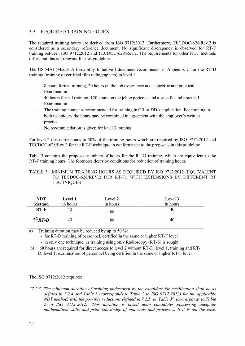
Table 3 contains the proposed numbers of hours for the RT-D training, which are equivalent to the RT-F training hours. The footnotes describe conditions for reduction of training hours.
TABLE 3. MINIMUM TRAINING HOURS AS REQUIRED BY ISO 9712:2012 (EQUIVALENT TO TECDOC-628/REV.2 FOR RT-F), WITH EXTENSIONS BY DIFFERENT RT TECHNIQUES
The ISO 9712:2012 requires:
“7.2.3 The minimum duration of training undertaken by the candidate for certification shall be as defined in 7.2.4 and Table 3 (corresponds to Table 2 in ISO 9712:2012) for the applicable
NDT method, with the possible reductions defined in 7.2.5. or Table 3a)
(corresponds to Table
2 in ISO 9712:2012). This duration is based upon candidates possessing adequate mathematical skills and prior knowledge of materials and processes. If it is not the case,
NDT
Method Level 1 in hours
Level 2 in hours
Level 3 in hours
RT-F
40 80
40
a,b)RT-D 40 80 40
a) Training duration may be reduced by up to 50 %:
- for RT-D training of personnel, certified in the same or higher RT-F level
- in only one technique, as training using only Radioscopy (RT-S) is sought
b) 60 hours are required for direct access to level 2 without RT-D, level 1, training and RT-D, level 1, examination of personnel being certified in the same or higher RT-F level.
24

25
additional training may be required by the certification body. Training hours include both
practical and theoretical courses.
7.2.4 Direct access to level 2 requires the total hours shown in Table 3 (corresponds to Table 2 in
ISO 9712:2012) for levels 1 and 2. Direct access to level 3 requires the total hours shown in Table 3 (corresponds to Table 2 in ISO 9712:2012) for levels 1, 2 and 3. When considering
the responsibilities of a certified level 3 (see 6.3 of ISO 9712:2012) and the content of the Part
C of the basic examination for level 3 (see Table 6 of ISO 9712:2012), additional training
about the other NDT methods may be necessary.
7.2.5 The possible reductions in training duration are as described hereafter, provided that, when several reductions are applicable, the total reduction does not exceed 50 % of the training
duration. Any reduction does require acceptance by the certification body.
- For all levels:
- For candidates seeking certification in more than one method (e.g. VT, MT, PT) or already
certificated and seeking certification in another method, when the used training syllabus
duplicates certain aspects (e.g. product technology), the total number of training hours for
these methods (e.g. VT, PT, MT) may be reduced in line with the training syllabus.
- For candidates who have graduated from technical college or university, or have completed at
least two years of engineering or science study at college or university, the total required
number of training hours may be reduced by up to 50 %.
- For levels 1 and 2: When the certification sought is limited:
- in application (e.g., automated ET, FLT, UT of bar, tube and rod, or normal beam ultrasonic
thickness and lamination testing of rolled steel plate), or
- in technique (e.g. RT using only Radioscopy), the training duration may be reduced by up to
50%.
- For direct access to level 2 RT when certification is restricted to the interpretation of film
or digital imagesa)
and to only one product sector, a minimum training requirement of 56 h
applies.”
Designation of training hours for different training contents can be found in the following Tables (see syllabi). No special reduction of training hours is proposed for candidates who have graduated from technical college or university, or have completed at least two years of engineering or science study at college or university in this guideline. These personnel may be certified with reduced experience times, if agreed by the certifying body.
ISO 9712:2012 and TECDOC-628/Rev.2 require for RT level 1 training 40 hours.
a)modified in addition to ISO 9712:2012.

27
4. TRAINING SYLLABI
The training syllabi are derived from the Guideline TECDOC-628/Rev.2, ISO 9712:2012, the German documents of the German Society for NDT, the MAI document and the current training booklet for level 2 training of IAEA. Also some information was taken from the results of the European Leonardo project [7].
The minimum duration of training undertaken by the candidate for certification in RT-D module 1 is defined in Table 5. The duration is based upon candidates possessing adequate mathematical skills and prior knowledge of materials and processes. If it is not the case, additional training may be required by the certification body. Training hours include both practical and theoretical courses.
Direct access to level 2 requires the total hours shown in Table 3 and 5 for levels 1 and 2. Direct access to level 3 requires the total hours shown in Table 3 and 5 for levels 1, 2 and 3.
Since regulations may exist for the radiation safety of personnel and handling of isotopic sources with separate training requirements in the different countries, the training hours are reduced in RT-D and RT-S (see Tables 5-7) down to two hours in the syllabi. Personnel has to prove the extra training and if required certification on basis on the national regulations and laws on radiation safety. Otherwise the training hours for radiation safety shall be extended in the RT-D and RT-S training course in agreement with TECDOC-628.
Furthermore, the training subject “general knowledge”, which is recommended in TECDOC-628 was shortened due to the enormous amount of other training subjects in digital radiology. The reference to other NDT methods and material defectology is partly integrated in the subject “Application and Standards”.
Different Syllabi are recommended for the training courses RT-D module 1 and 2 and RT-S (see Tables 5-7).
Since Computed Tomography is not yet a common technique in the IAEA member states and the major industries, a separated training syllabus for CT is not recommended yet. CT will be introduced by a lecture and a numeric modeling based exercise. If specialized training of CT is required, the training hours may be increased or a separated training course may be conducted.
Table 6 and Table 7 show the breakdown of training hours for RT-D module 2 for RT-F certified personal (film replacement), and for radioscopy operators (RT-S) in serial production, without required certification. Due to the serious differences in the training contents between RT-F, RT-S and RT-D, it is recommended in this guideline to increase the training hours for RT-D module 2 and RT-S to more hours than required by the 50% rule of Table 3. The required hours for training in RT-D and RT-S, Module 2, are listed in Table 9.
4.1. TRAINING CONTENTS FOR DIFFERENT SUBJECTS
Tables 5-7 describe the coarse syllabi for the three training modules RT-D, Module 1 and 2 and RT-S. Training organizations may modify the proposed number of hours depending on the national needs.
The MAI document [6] describes also a syllabus for RT-D training in level 1-3, which is similar to Table 4 and Tables 5-7, but shows also some differences. In the Leonardo [7] project complete training handbooks were published for RT-F, considering some digital and tomographic aspects. Relevant training contents as required for RT-F in ISO TR 25107 [8] should be considered for RT-D and RT-S as well.
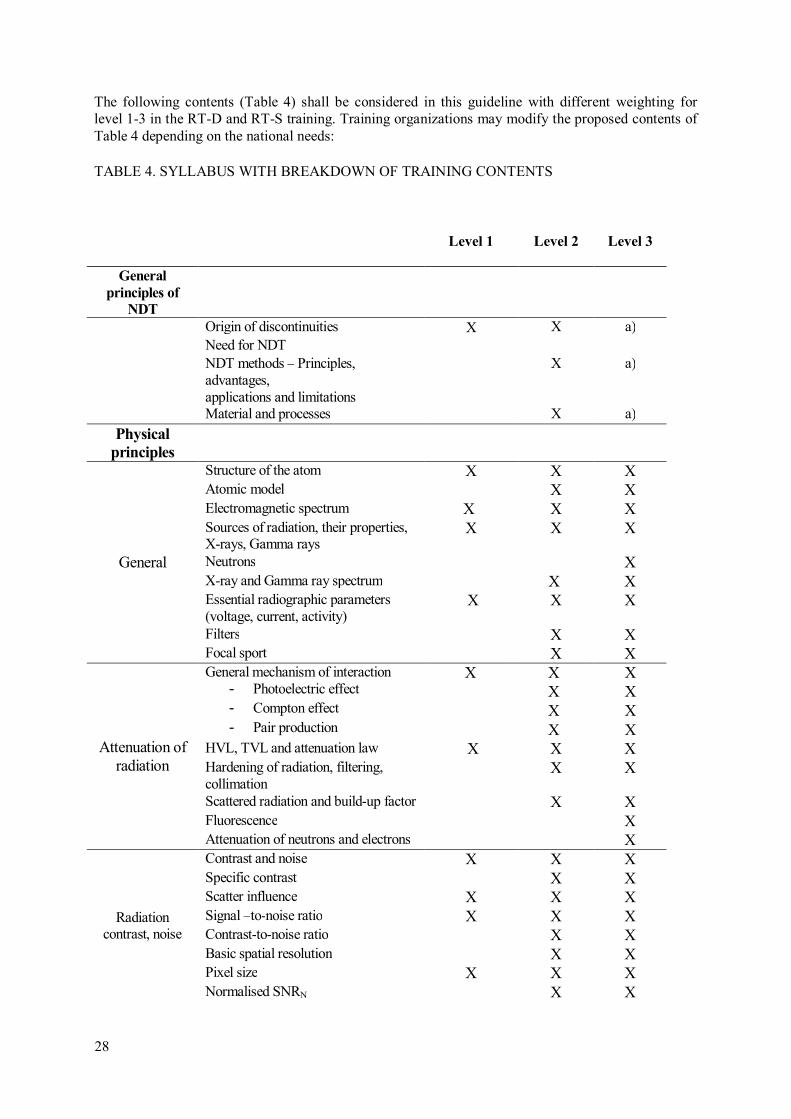
The following contents (Table 4) shall be considered in this guideline with different weighting for level 1-3 in the RT-D and RT-S training. Training organizations may modify the proposed contents of Table 4 depending on the national needs:
TABLE 4. SYLLABUS WITH BREAKDOWN OF TRAINING CONTENTS
Level 1
Level 2
Level 3
General
principles of
NDT
Origin of discontinuities X X a)
Need for NDT
NDT methods – Principles, advantages, applications and limitations
X a)
Material and processes X a)
Physical
principles
General
Structure of the atom X X X Atomic model X X Electromagnetic spectrum X X X Sources of radiation, their properties, X-rays, Gamma rays
X X X
Neutrons X X-ray and Gamma ray spectrum X X Essential radiographic parameters (voltage, current, activity)
X X X
Filters X X Focal sport X X
Attenuation of radiation
General mechanism of interaction - Photoelectric effect - Compton effect
- Pair production
X X X X X X X X X
HVL, TVL and attenuation law X X X Hardening of radiation, filtering, collimation
X X
Scattered radiation and build-up factor X X Fluorescence X Attenuation of neutrons and electrons X
Radiation contrast, noise
Contrast and noise X X X Specific contrast X X Scatter influence X X X Signal –to-noise ratio X X X Contrast-to-noise ratio X X Basic spatial resolution X X Pixel size X X X Normalised SNRN X X
28
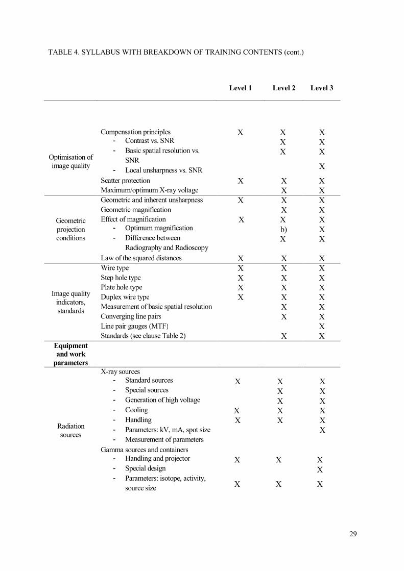
29
TABLE 4. SYLLABUS WITH BREAKDOWN OF TRAINING CONTENTS (cont.)
Level 1
Level 2
Level 3
Optimisation of image quality
Compensation principles - Contrast vs. SNR
- Basic spatial resolution vs. SNR
- Local unsharpness vs. SNR
X X X X X X X
X
Scatter protection X X X Maximum/optimum X-ray voltage X X
Geometric projection conditions
Geometric and inherent unsharpness X X X Geometric magnification X X Effect of magnification
- Optimum magnification
- Difference between Radiography and Radioscopy
X X X b) X X X
Law of the squared distances X X X
Image quality indicators, standards
Wire type X X X Step hole type X X X Plate hole type X X X Duplex wire type X X X Measurement of basic spatial resolution X X Converging line pairs X X Line pair gauges (MTF) X Standards (see clause Table 2) X X
Equipment
and work
parameters
Radiation sources
X-ray sources - Standard sources - Special sources
- Generation of high voltage
- Cooling
- Handling
- Parameters: kV, mA, spot size - Measurement of parameters
X X X X X X X
X X X X X X X
Gamma sources and containers - Handling and projector
- Special design
- Parameters: isotope, activity, source size
X X X X
X X X
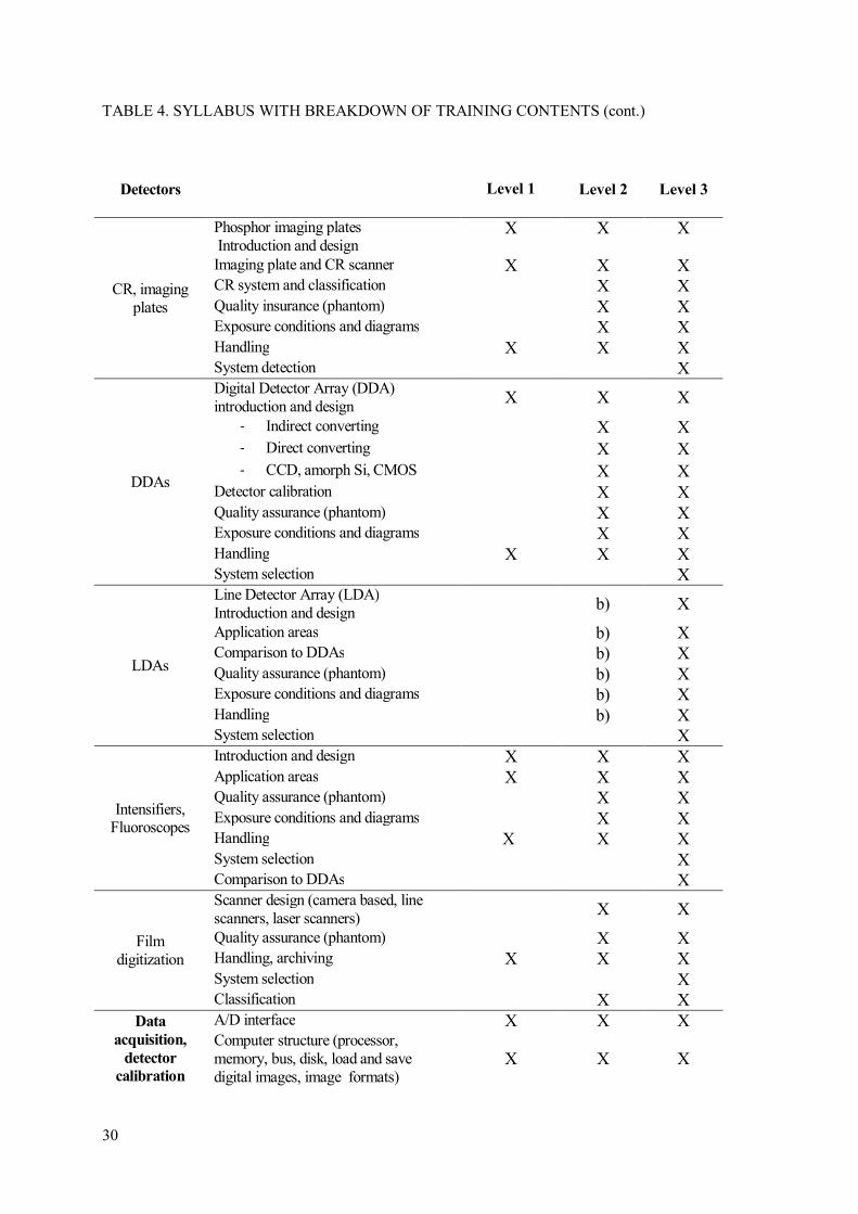
TABLE 4. SYLLABUS WITH BREAKDOWN OF TRAINING CONTENTS (cont.)
Detectors
Level 1
Level 2
Level 3
CR, imaging plates
Phosphor imaging plates Introduction and design
X X X
Imaging plate and CR scanner X X X CR system and classification X X Quality insurance (phantom) X X Exposure conditions and diagrams X X Handling X X X System detection X
DDAs
Digital Detector Array (DDA) introduction and design
X X X
- Indirect converting X X - Direct converting X X - CCD, amorph Si, CMOS X X
Detector calibration X X Quality assurance (phantom) X X Exposure conditions and diagrams X X Handling X X X System selection X
LDAs
Line Detector Array (LDA) Introduction and design
b) X
Application areas b) X Comparison to DDAs b) X Quality assurance (phantom) b) X Exposure conditions and diagrams b) X Handling b) X System selection X
Intensifiers, Fluoroscopes
Introduction and design X X X Application areas X X X Quality assurance (phantom) X X Exposure conditions and diagrams X X Handling X X X System selection X Comparison to DDAs X
Film digitization
Scanner design (camera based, line scanners, laser scanners)
X X
Quality assurance (phantom) X X Handling, archiving X X X System selection X Classification X X
Data
acquisition,
detector
calibration
A/D interface X X X Computer structure (processor, memory, bus, disk, load and save digital images, image formats)
X X X
30

31
TABLE 4. SYLLABUS WITH BREAKDOWN OF TRAINING CONTENTS (cont.)
Level 1 Level 2 Level 3
Image integration (on chip, in memory, optimum gain and latitude settings, accumulation vs. integration)
X X
Digital image
processing
Image structure, quantisation (bits and Bytes)
X X X
Basic operation - Picture element (pixel)
- Grey value X X X
Point operations - Contrast, brightness, gamma
correction - Histogram
- Look up Table (LUT)
X X X X X
X X
Matrix operations , filters - Smoothing, improvement of
SNR - High pass, gradient
- Edge enhancement, line
extraction - median
X X
Measurement tools - Calibration
- Line profile
- Measurement of flaw length - Measurement of areas
- Measurement of depth
X X
Correction of raw data - Linearization, Look up Table
(LUT) correction - Bad pixel interpolation
X X
Standards
Guides X X Qualification of sources X General qualification of detectors X User qualification of detectors X X See Table 2 X
Defectology,
digital
catalogues
General Welding (ISO 6520) and Casting Defects (ASTM casting catalogues)
X X X
Evaluation of welding : IIW catalogue ISO 5817
X X
Evaluation of Casting: ASTM catalogues X X
Corrosion X X X
Automated
image
interpretation
Principles X X Binarisation X X Measurement of dimensions X X

Level 1
Level 2 Level 3
b) Special
techniques,
computed
tomography
Stereo radiography X X Laminography X Computed Tomography
- Inspection geometry - 2D vs. 3D
- Reconstruction principles
- Filtered back projection
- Applications
- Requirements and limit of
method
X X
See also clause 4.4
X extra
Applications Standard
practice and evaluation
Selection of technique
Welds - Standard practice with
different exposure geometries - Interpretation of digital images
- Digital processing of images
- Evaluation of flaws
- Measurement of flaw
dimensions - Written instruction/procedure
X X X
Castings - Standard practice with
different exposure geometries - Interpretation of digital images
- Digital processing of images
- Evaluation of flaws
- Use of catalogues (see above)
- Measurement of flaw dimensions
- Written instruction/procedure
X X X
Corrosion wall thickness measurement - Tangential RT - Double wall RT
- Calibration of digital images
- Measurement of thickness
- Written instruction/procedure
X X X
Others… X X Written
procedure/ instructions
Welds X X Castings X X Corrosion with thickness measurement X X
Radiation protection
Training courses depending on national regulations
c) c) c)
Notes:
TABLE 4. SYLLABUS WITH BREAKDOWN OF TRAINING CONTENTS (cont.)
32

33
a) In addition to the above 40 hours a general knowledge common core course for level 3 (applicable to all NDT methods) is recommended, which shall be successfully completed only once.
b) Especially for RT-CT/RT-S related training.
c) National laws and regulations are to be considered for training on radiation safety and handling of radiation sources. Radiation safety may be trained in separated courses, or training hours should be considered to be additional to those of the syllabus requirements (see TECDOC-628/Rev.2).
4.2. EXAMPLE OF RECOMMENDED PRACTICAL EXERCISES FOR PRACTICAL TRAINING IN RT-D MODULE 2, LEVEL 2
The practical training should be organized by written exercises with description of training tasks and forms for analysis of the performed experiments. The exercises (about 4 hours per day) should be carried out at all seven days of training for RT-D module 2 as follows:
- 1st day setup of computers, monitor test, installation of training software
• Training in handling of viewer software, brightness, contrast control
• Measuring of image quality (Wires, duplex wire, plate holes, step holes)
o Determination of basic spatial resolution, SNR, CNR and µeff
• Viewing of test images
- 2nd day film digitization with reference films or CR of quality assurance phantom or radioscopy
• Digitization of reference film or exposure of CR phantom (Film: ASTM E 1936, CR:
ASTM E 2445)
• Analysis of image quality
• Documentation
- 3rd day test measurements with digital detector arrays of castings by standard practice ASTM E
2698 and application of ASTM digital reference catalogues
• Selection of exposure conditions
• Exposure of test objects (casting)
• Analysis of image quality, evaluation of detected flaws with digital catalogues
• Written procedure and documentation
- 4th day measurement of exposure diagram for CR by draft ASTM 2033 or ISO 17636-2
- 5th day test measurements with computed radiography of welds by standard practice ISO 17636-2 and ASME BPVC S. V and TRT for pipe walls.
• Exposure of test objects (welds, pipes)
• Analysis of image quality, evaluation of detected flaws by ISO 5817 and
• Wall thickness measurement
• Documentation
- 6th day Virtual training
• CT,
• Flaw segmentation
• Defect measurement
• Virtual optimization of exposure conditions
- 7th day optimization of image processing and training of written procedure for image
processing.

TA
BL
E 5
. BR
EA
K D
OW
N O
F T
RA
ININ
G H
OU
RS
FO
R A
LL
LE
VE
LS
OF
RT
-D M
OD
UL
E 1
Syll
ab
us
for
Dig
ital
Ind
ust
rial
Rad
iolo
gy R
T-D
-
Mod
ule
1
Tra
inin
g sy
llabu
s L
evel
1 h
ours
L
evel
2 h
ours
L
evel
3 h
ours
L
ectu
re
Prac
tice
Lec
ture
Pr
actic
e L
ectu
re
Prac
tice
Gen
eral k
now
led
ge
ND
T
1 0
2.5
0 a)
0
Physi
cal p
rinci
ple
s of X
-ray t
echn
ique
2 0.
25
4.75
0
2.45
0
Rad
iati
on c
ontr
ast
, nois
e 1.
5 1
3 3.
5 1.
2 0
b) G
eom
etri
cal p
roje
ctio
n c
ond
itio
ns
1.5
2 1
1.5
1 0.
5 O
pti
mis
ati
on o
f im
age
quality
1
1 1.
75
1.5
1.5
0 Im
age
quality
ind
icato
rs, st
and
ard
s 1
2 1
0 0.
5 0.
5 E
quip
men
t and
work
– R
ad
iati
on s
ourc
es
- X
-Ray
sou
rces
- G
amm
a so
urce
s 2
2 3.
5 2
2.5
0.5
Eq
uip
men
t and
work
– d
etec
tors
: C
R,
imagin
g p
late
s 2
2 1.
75
2.25
1.
5 0.
5
Eq
uip
men
t and
work
– d
etec
tors
: D
DA
s 2
2 2
2 2
0 E
quip
men
t and
work
– d
etec
tors
: L
DA
s 0
0 0.
5 0
1 0
Eq
uip
men
t and
work
– d
etec
tors
:
inte
nsi
fier
s, f
luoro
scop
e 0
0 1.
25
0.25
1
0
Eq
uip
men
t and
work
– d
etec
tors
: f
ilm
dig
itiz
ati
on
0 0
0.5
0 0.
5 0
Data
acq
uis
itio
n, d
etec
tor
calib
rati
on
0
0 2
2 1
1 D
igit
al im
age
pro
cess
ing
(t
ota
l)
2 2.
75
7 7
3.1
2.5
Imag
e st
ruct
ure,
qua
ntis
atio
n
(bits
and
byt
es)
0.25
0.5
0.
25
Bas
ic o
pera
tion
0.75
1
0.5
0.
25
P
oint
ope
ratio
ns
1 1
1 1
0.25
0.
5 M
atri
x op
erat
ions
, filt
er
3 3
1.5
1 M
easu
rem
ent t
ools
0.75
1
2 0.
35
1 C
orre
ctio
n of
raw
dat
a
1
1 0.
5
34
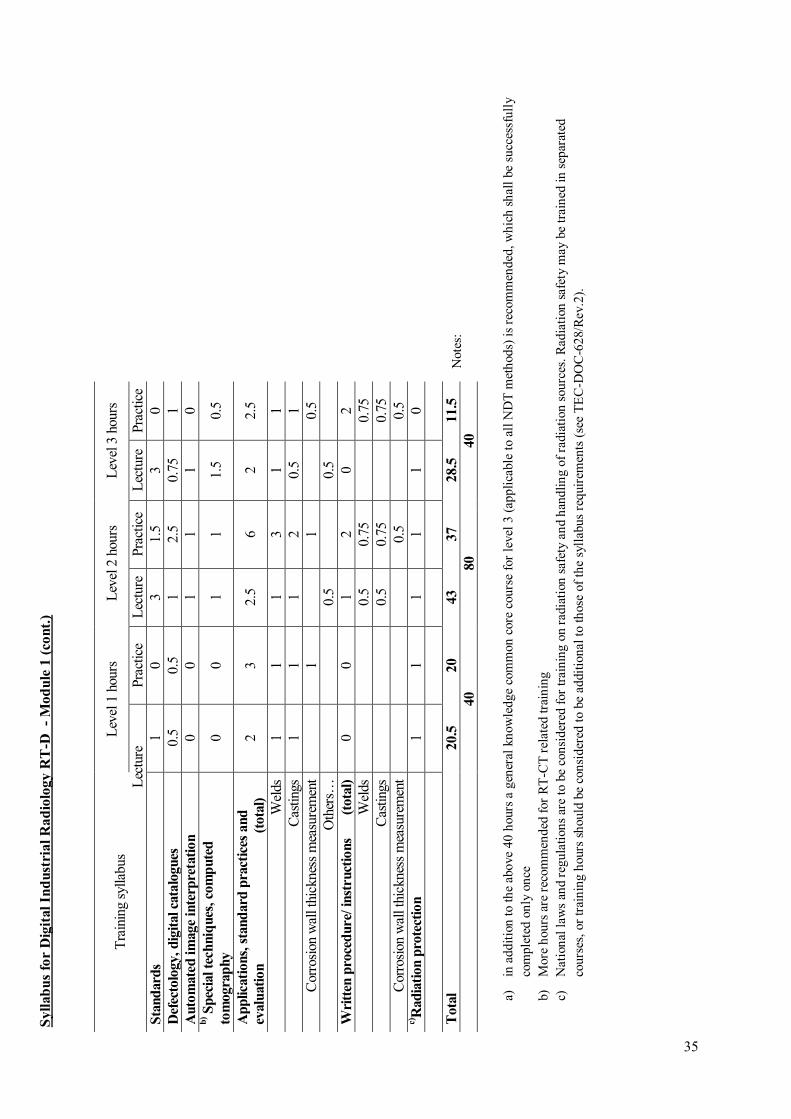
35
Not
es:
a)
in a
ddit
ion
to th
e ab
ove
40 h
ours
a g
ener
al k
now
ledg
e co
mm
on c
ore
cour
se f
or l
evel
3 (
appl
icab
le t
o al
l ND
T m
etho
ds)
is r
ecom
men
ded,
whi
ch s
hall
be
succ
essf
ully
co
mpl
eted
onl
y on
ce
b)
Mor
e ho
urs
are
reco
mm
ende
d fo
r R
T-C
T r
elat
ed tr
aini
ng
c)
Nat
iona
l law
s an
d re
gula
tion
s ar
e to
be
cons
ider
ed f
or tr
aini
ng o
n ra
diat
ion
safe
ty a
nd h
andl
ing
of r
adia
tion
sou
rces
. Rad
iati
on s
afet
y m
ay b
e tr
aine
d in
sep
arat
ed
cour
ses,
or
trai
ning
hou
rs s
houl
d be
con
side
red
to b
e ad
diti
onal
to
thos
e of
the
syl
labu
s re
quir
emen
ts (
see
TE
C-D
OC
-628
/Rev
.2).
T
rain
ing
sylla
bus
Lev
el 1
hou
rs
Lev
el 2
hou
rs
Lev
el 3
hou
rs
Lec
ture
Pr
actic
e L
ectu
re
Prac
tice
Lec
ture
Pr
actic
e S
tand
ard
s 1
0 3
1.5
3 0
Def
ecto
logy, d
igit
al ca
talo
gues
0.
5 0.
5 1
2.5
0.75
1
Auto
mate
d im
age
inte
rpre
tati
on
0
0 1
1 1
0 b
) Sp
ecia
l te
chniq
ues
, co
mp
ute
d
tom
ogra
phy
0 0
1 1
1.5
0.5
Ap
plica
tions,
sta
nd
ard
pra
ctic
es a
nd
evalu
ati
on
(t
ota
l)
2 3
2.5
6 2
2.5
Wel
ds
1 1
1 3
1 1
Cas
tings
1
1 1
2 0.
5 1
Cor
rosi
on w
all t
hick
ness
mea
sure
men
t
1
1
0.5
Oth
ers…
0.
5
0.5
W
ritt
en p
roce
dure
/ in
stru
ctio
ns
(to
tal)
0
0 1
2 0
2 W
elds
0.
5 0.
75
0.
75
Cas
tings
0.
5 0.
75
0.
75
Cor
rosi
on w
all t
hick
ness
mea
sure
men
t
0.5
0.
5 c)R
ad
iati
on p
rote
ctio
n
1 1
1 1
1 0
T
ota
l 20.5
20
43
37
28.5
11.5
40
80
40
Syll
ab
us
for
Dig
ital
Ind
ust
rial
Rad
iolo
gy R
T-D
-
Mod
ule
1 (
con
t.)
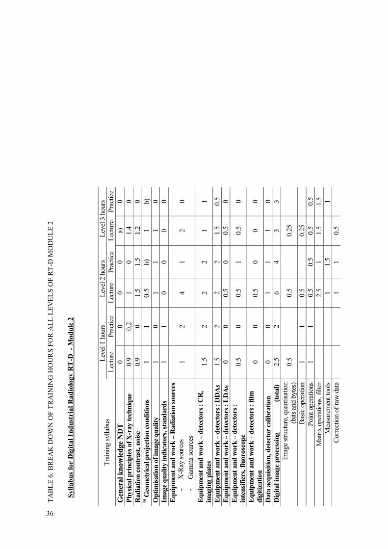
TA
BL
E 6
. BR
EA
K D
OW
N O
F T
RA
ININ
G H
OU
RS
FO
R A
LL
LE
VE
LS
OF
RT
-D M
OD
UL
E 2
Tra
inin
g sy
llabu
s L
evel
1 h
ours
L
evel
2 h
ours
L
evel
3 h
ours
L
ectu
re
Prac
tice
Lec
ture
Pr
actic
e L
ectu
re
Prac
tice
Gen
eral k
now
led
ge
ND
T
0 0
0 0
a)
0 P
hysi
cal p
rinci
ple
s of X
-ray t
echn
ique
0.9
0.2
1 0
1.4
0 R
ad
iati
on c
ontr
ast
, nois
e 0.
9 0
1.5
1.5
1.2
0 b
) Geo
met
rica
l p
roje
ctio
n c
ond
itio
ns
1 1
0.5
b)
1 b)
O
pti
mis
ati
on o
f im
age
quality
1
0 1
1 1
0 Im
age
quality
ind
icato
rs, st
and
ard
s 1
1 0
0 0
0 E
quip
men
t and
work
– R
ad
iati
on s
ourc
es
- X
-Ray
sou
rces
- G
amm
a so
urce
s 1
2 4
1 2
0
Eq
uip
men
t and
work
– d
etec
tors
: C
R,
imagin
g p
late
s 1.
5 2
2 2
1 1
Eq
uip
men
t and
work
– d
etec
tors
: D
DA
s 1.
5 2
2 2
1.5
0.5
Eq
uip
men
t and
work
– d
etec
tors
: L
DA
s 0
0 0.
5 0
0.5
0 E
quip
men
t and
work
– d
etec
tors
:
inte
nsi
fier
s, f
luoro
scop
e 0.
5 0
0.5
1 0.
5 0
Eq
uip
men
t and
work
– d
etec
tors
: f
ilm
dig
itiz
ati
on
0 0
0.5
0 0
0
Data
acq
uis
itio
n, d
etec
tor
calib
rati
on
0
0 1
1 1
0 D
igit
al im
age
pro
cess
ing
(t
ota
l)
2.5
2 6
4 3
3 Im
age
stru
ctur
e, q
uant
isat
ion
(b
its a
nd b
ytes
) 0.
5
0.5
0.
25
Bas
ic o
pera
tion
1 1
0.5
0.
25
P
oint
ope
ratio
ns
1 1
0.5
0.5
0.5
0.5
Mat
rix
oper
atio
ns, f
ilter
2.
5 1
1.5
1.5
Mea
sure
men
t too
ls
1 1.
5
1 C
orre
ctio
n of
raw
dat
a
1
1 0.
5
Syll
ab
us
for
Dig
ital
Ind
ust
rial
Rad
iolo
gy R
T-D
-
Mod
ule
2
36
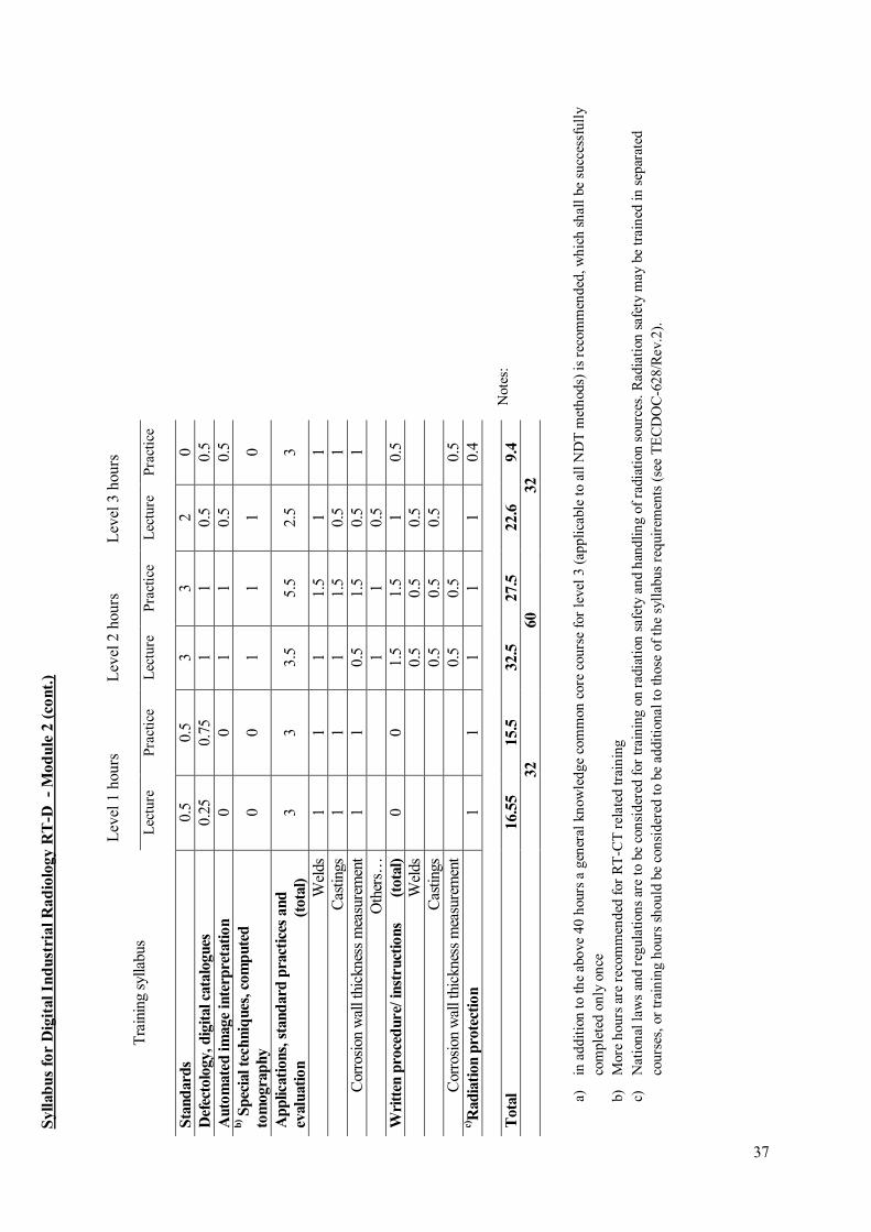
37
Not
es:
a)
in a
ddit
ion
to th
e ab
ove
40 h
ours
a g
ener
al k
now
ledg
e co
mm
on c
ore
cour
se f
or l
evel
3 (
appl
icab
le t
o al
l ND
T m
etho
ds)
is r
ecom
men
ded,
whi
ch s
hall
be
succ
essf
ully
co
mpl
eted
onl
y on
ce
b)
Mor
e ho
urs
are
reco
mm
ende
d fo
r R
T-C
T r
elat
ed tr
aini
ng
c)
Nat
iona
l law
s an
d re
gula
tion
s ar
e to
be
cons
ider
ed f
or tr
aini
ng o
n ra
diat
ion
safe
ty a
nd h
andl
ing
of r
adia
tion
sou
rces
. Rad
iati
on s
afet
y m
ay b
e tr
aine
d in
sep
arat
ed
cour
ses,
or
trai
ning
hou
rs s
houl
d be
con
side
red
to b
e ad
diti
onal
to
thos
e of
the
syl
labu
s re
quir
emen
ts (
see
TE
CD
OC
-628
/Rev
.2).
Tra
inin
g sy
llabu
s
Lev
el 1
hou
rs
Lev
el 2
hou
rs
Lev
el 3
hou
rs
Lec
ture
P
ract
ice
Lec
ture
P
ract
ice
Lec
ture
P
ract
ice
Sta
nd
ard
s 0.
5 0.
5 3
3 2
0 D
efec
tolo
gy, d
igit
al ca
talo
gues
0.
25
0.75
1
1 0.
5 0.
5 A
uto
mate
d im
age
inte
rpre
tati
on
0
0 1
1 0.
5 0.
5 b
) Sp
ecia
l te
chniq
ues
, co
mp
ute
d
tom
ogra
phy
0 0
1 1
1 0
Ap
plica
tions,
sta
nd
ard
pra
ctic
es a
nd
evalu
ati
on
(t
ota
l)
3 3
3.5
5.5
2.5
3
Wel
ds
1 1
1 1.
5 1
1 C
astin
gs
1 1
1 1.
5 0.
5 1
Cor
rosi
on w
all t
hick
ness
mea
sure
men
t 1
1 0.
5 1.
5 0.
5 1
Oth
ers…
1
1 0.
5
Wri
tten
pro
ced
ure
/ in
stru
ctio
ns
(to
tal)
0
0 1.
5 1.
5 1
0.5
Wel
ds
0.5
0.5
0.5
C
astin
gs
0.5
0.5
0.5
C
orro
sion
wal
l thi
ckne
ss m
easu
rem
ent
0.5
0.5
0.
5 c)R
ad
iati
on p
rote
ctio
n
1 1
1 1
1 0.
4
Tota
l 16.5
5
15.5
32.5
27.5
22.6
9.4
32
60
32
Syll
ab
us
for
Dig
ital
Ind
ust
rial
Rad
iolo
gy R
T-D
-
Mod
ule
2 (
con
t.)

TA
BL
E 7
. BR
EA
K D
OW
N O
F T
RA
ININ
G H
OU
RS
FO
R A
LL
LE
VE
LS
OF
RT
-S
Tra
inin
g sy
llabu
s L
evel
1 h
ours
L
evel
2 h
ours
L
evel
3 h
ours
L
ectu
re
Prac
tice
Lec
ture
Pr
actic
e L
ectu
re
Prac
tice
Gen
eral k
now
led
ge
ND
T
0 0
0 0
a)
0 P
hysi
cal p
rinci
ple
s of X
-ray t
echn
ique
1 0.
5 1
0 1
0 R
ad
iati
on c
ontr
ast
, nois
e 1
0 1
1 1
0 b
) Geo
met
rica
l p
roje
ctio
n c
ond
itio
ns
1.5
2 2
2 2
1 O
pti
mis
ati
on o
f im
age
quality
1
0 1
1 1
0 Im
age
quality
ind
icato
rs, st
and
ard
s 1
1 0
0 0
0 E
quip
men
t and
work
– R
ad
iati
on s
ourc
es
- X
-Ray
sou
rces
- G
amm
a so
urce
s 1
2 1
1 1.
5 0
Eq
uip
men
t and
work
– d
etec
tors
: C
R,
imagin
g p
late
s 1
0 1
0 1
0
Eq
uip
men
t and
work
– d
etec
tors
: D
DA
s 1.
5 1
1 1
1 1
Eq
uip
men
t and
work
– d
etec
tors
: L
DA
s 0.
5 0
0.5
0 0.
5 0
Eq
uip
men
t and
work
– d
etec
tors
:
inte
nsi
fier
s, f
luoro
scop
e 1
1 1
1 0.
5 0.
5
Eq
uip
men
t and
work
– d
etec
tors
: f
ilm
dig
itiz
ati
on
0 0
0 0
0 0
Data
acq
uis
itio
n, d
etec
tor
calib
rati
on
0
0 1
1 1
0 D
igit
al im
age
pro
cess
ing
(t
ota
l)
2 2
5 4
3 3
Imag
e st
ruct
ure,
qua
ntis
atio
n
(bits
and
byt
es)
0.5
0.
5
0.25
Bas
ic o
pera
tion
0.75
1
0.5
0.
25
P
oint
ope
ratio
ns
0.75
1
0.5
0.5
0.5
0.5
Mat
rix
oper
atio
ns, f
ilter
2
1 1.
5 1.
5 M
easu
rem
ent t
ools
0.
5 1.
5
1 C
orre
ctio
n of
raw
dat
a
1
1 0.
5
Syll
ab
us
for
Dig
ital
Ind
ust
rial
Rad
iolo
gy R
T-S
38
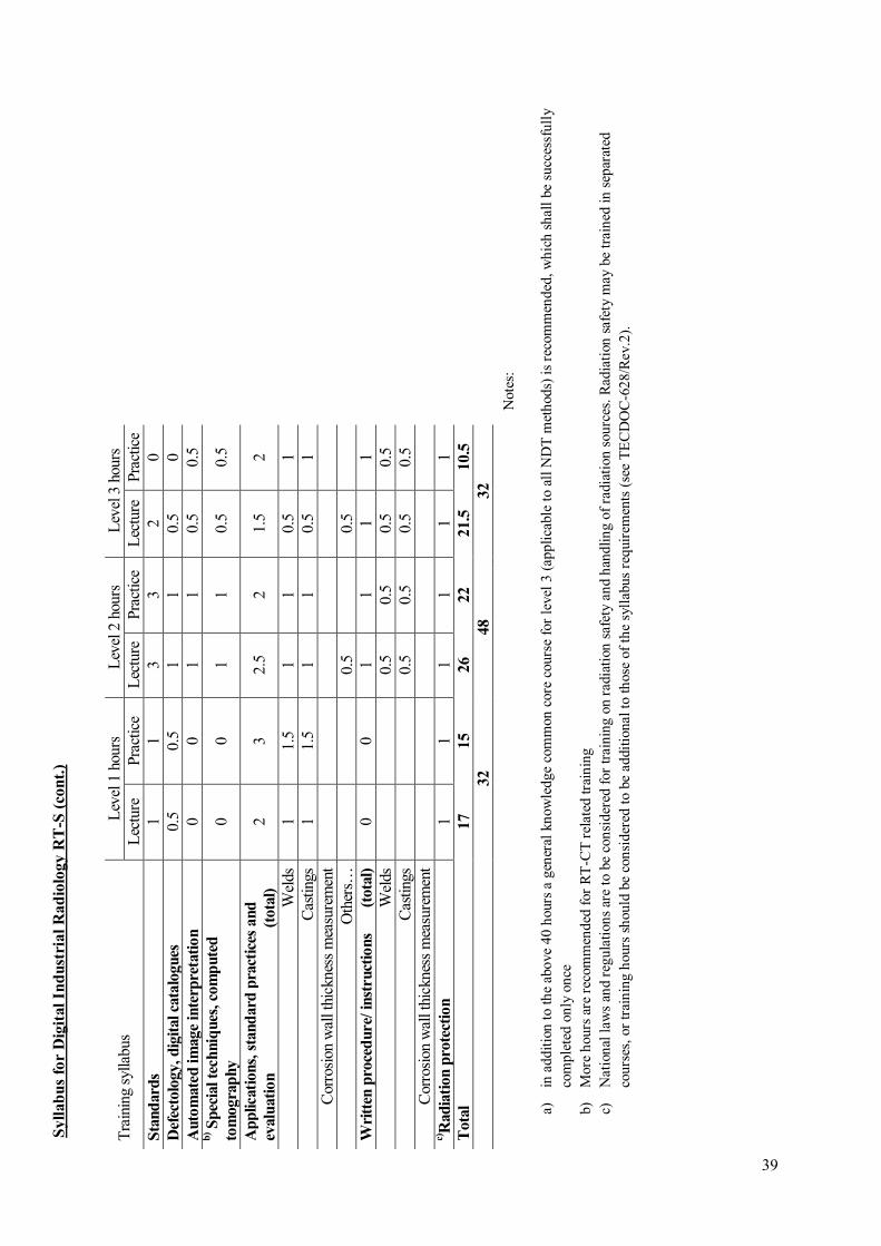
39
Not
es:
a)
in a
ddit
ion
to th
e ab
ove
40 h
ours
a g
ener
al k
now
ledg
e co
mm
on c
ore
cour
se f
or l
evel
3 (
appl
icab
le t
o al
l ND
T m
etho
ds)
is r
ecom
men
ded,
whi
ch s
hall
be
succ
essf
ully
co
mpl
eted
onl
y on
ce
b)
Mor
e ho
urs
are
reco
mm
ende
d fo
r R
T-C
T r
elat
ed tr
aini
ng
c)
Nat
iona
l law
s an
d re
gula
tion
s ar
e to
be
cons
ider
ed f
or tr
aini
ng o
n ra
diat
ion
safe
ty a
nd h
andl
ing
of r
adia
tion
sou
rces
. Rad
iati
on s
afet
y m
ay b
e tr
aine
d in
sep
arat
ed
cour
ses,
or
trai
ning
hou
rs s
houl
d be
con
side
red
to b
e ad
diti
onal
to
thos
e of
the
syl
labu
s re
quir
emen
ts (
see
TE
CD
OC
-628
/Rev
.2).
Tra
inin
g sy
llabu
s L
evel
1 h
ours
L
evel
2 h
ours
L
evel
3 h
ours
L
ectu
re
Prac
tice
Lec
ture
Pr
actic
e L
ectu
re
Prac
tice
Sta
nd
ard
s 1
1 3
3 2
0 D
efec
tolo
gy, d
igit
al ca
talo
gues
0.
5 0.
5 1
1 0.
5 0
Auto
mate
d im
age
inte
rpre
tati
on
0
0 1
1 0.
5 0.
5 b
) Sp
ecia
l te
chniq
ues
, co
mp
ute
d
tom
ogra
phy
0 0
1 1
0.5
0.5
Ap
plica
tions,
sta
nd
ard
pra
ctic
es a
nd
evalu
ati
on
(t
ota
l)
2 3
2.5
2 1.
5 2
Wel
ds
1 1.
5 1
1 0.
5 1
Cas
tings
1
1.5
1 1
0.5
1 C
orro
sion
wal
l thi
ckne
ss m
easu
rem
ent
Oth
ers…
0.
5
0.5
W
ritt
en p
roce
dure
/ in
stru
ctio
ns
(to
tal)
0
0 1
1 1
1 W
elds
0.
5 0.
5 0.
5 0.
5 C
astin
gs
0.5
0.5
0.5
0.5
Cor
rosi
on w
all t
hick
ness
mea
sure
men
t
c)R
ad
iati
on p
rote
ctio
n
1 1
1 1
1 1
Tota
l 17
15
26
22
21.5
10.5
32
48
32
Syll
ab
us
for
Dig
ital
Ind
ust
rial
Rad
iolo
gy R
T-S
(co
nt.
)
4.3. TRAINING COMPUTED TOMOGRAPHY
It is recommended to develop a separated training course for computed tomography (RT-CT) if required. Computed tomography is a very specialized technology and should be combined with instructions on handling of the CT device and CT software, depending on the manufacturer’s manual. Nevertheless, CT was included as informative training in level 2 and 3 since it is essential that RT-DR personnel have knowledge and an understanding of the basics and potential of this technology.
The MAI document [6] proposes to include CT in the level 3 training, extensively. The following syllabus is recommended in this document for CT as part of level 3 training:
Computed tomography testing:
- Difference between CT and conventional radiography; - Benefits and Advantages;
- Limitations;
- Industrial imaging examples;
- Basic Hardware Configuration;
- Scan geometries – general configurations by generation;
- Radiation sources; - Detection systems;
- Convolution/Back projections;
- Fourier Reconstructions;
- Fan / Cone Beam;
- Advanced Image Processing and Algorithm Analysis; - Fundamental CT Performance Parameters;
- System performance analysis;
- Fundamental scan plan parameters;
- Basic system tradeoffs for spatial resolution/noise/slice thickness;
- Basic Image Interpretation;
- Artifacts – definitions, detection and basic causes.
A part of these requirements is covered in lecture L16 as described in Annex I for level 2 training. Practical training is not included in the current training program. Since most NDT training organisations do not have CT equipment, virtual training is proposed, e.g. with the aRTist training software (see clause 5 and [12]), which would require an extension of the training hours.
40

41
5. VIRTUAL TRAINING FOR RT-D AND CT
The practical training with computed radiography devices, X-ray intensifiers or digital detector arrays, requires expensive hardware with costs of up to US$150,000 per system and the training is very time consuming because the personnel cannot train in the same room due to radiation protection concerns. Practical training, therefore, has to be organized in groups and each group has to wait until the previous group has finalized their training.
Virtual training tools for training of digital radiography are available for computer based application [12]. The advantages are:
- All trainees can work in parallel with different exposure techniques.
- No radiation protection has to be considered.
- No waiting times are required except handling at the computer and documentation of results.
Disadvantages are:
- Trainees do not train RT-D under practical conditions with real hardware
- No training of hardware specific handling is performed
- No practical radiation protection measures are trained
In conclusion the practical training in one or two techniques may be substituted by virtual training, but at least one technique (CR, DDA or Radioscopy with intensifier or fluoroscope) shall be trained under real radiation conditions.
The virtual training with the software package aRTist [12] was successfully used for training of virtual inspection of welds, castings, pipes and for Computed Tomography. Training was performed in 2009 in India and Malaysia and 2010 in Republic of Korea. It is also used for level 3 RT training by the DGZfP.
FIG.15. Typical image of a RT-D inspection of a light alloy castings.
FIG. 15a.
Virtual inspection of an aluminum casting with flaws and
IQIs [12]. Left: Opening window of aRTist software package, controlling the inspection parameters. Right: CAD of the test piece for virtual inspection.
FIG. 15b.
Left: Result of virtual X-ray inspection.
Right: Presentation of the test piece in transparent mode for visualization of the flaws.

Fig. 15 shows a typical image of a RT-D inspection of a light alloy casting. The surface data of the casting, the IQIs and the flaws, are provided as CAD file in .stl format. A combined material specific data set is provided for different test objects with flaws and IQIs. The students select the correct exposure conditions as e.g. X-ray voltage, source detector distance, focal spot size, detector type and detector parameters. Then, they calculate the corresponding digital radiograph with the modeling software. The IQI values, SNR, basic spatial resolution and the recognized flaws are documented as result of the training. This procedure can also be used for examination of candidates. The virtual digital images produced are equivalent to real exposures. The image interpretation and documentation after virtual exposures is equivalent to interpretation and documentation of practical exposures and, therefore, the virtual radiography can be used in lieu of practical training or practical examination.
42

43
6. QUALIFICATION EXAMINATION
6.1. NUMBER OF QUESTIONS FOR GENERAL AND SPECIFIC EXAMINATION
ISO 9712:2012 specifies the conditions for the qualification examination. For the complete information the standard shall be referenced.
Here is a summary of the most important requirements for level 1 and 2 examination:
- The Certification Body shall define and publish the maximum amount of time allowed for the
completion of each examination.
- The written tests of the "general" and "specific" examinations are assessed by comparing the
replies given by the candidate against answer keys approved by the certification body.
- Each correct reply scores 1 point and the mark attributed to the test is equal to the sum of
points obtained. For the final calculation, the mark of each test is expressed as a percentage.
- The candidate shall be required, as a minimum, to give answers to the number of multiple choice questions shown in Table 4 of ISO 9712:2012.
- Where not otherwise addressed by national regulations, there shall be an additional examination on radiation safety for the radiographic test method.
- The general part shall consist of 40 multiple choice questions independently on the level and training hours for RT-D, and RT-S.
- The specific examination shall include only questions selected from the examination question databank of the certification body, or that of the authorised qualifying body that has been
approved by the certifying body.
- During the specific examination, the candidate shall be required to give answers to at least 20
multiple-choice questions, including questions involving calculations, written procedures and questions on codes, standards and specifications.
- If the specific examination covers two or more sectors, the minimum number of questions
shall be at least 30 (level 1 and 2), evenly spread between the sectors concerned.
In conclusion of these requirements the general examination shall consist of 40 questions and the
specific one for more than one industrial sector shall consist of 30 questions for RT-D, or RT-S
(level 1 and 2). See also Table 11.
Here is a summary of the most important requirements for level 3 examination:
For level 3 the ISO 9712:2012 gives guidance in clause 8.3. The candidate needs additionally a basic examination which is widely independent on the method to examine. Four test methods shall be covered. One of the methods should be RT-F. 60 questions shall be answered for the four test methods. 35 questions shall cover the knowledge in material science and process technology as well as certification systems. He needs furthermore the level 2 certificate or at least the successfully passed practical level 2 examination. See for more details in ISO 9712:2012.
The main examination consists of 30 general questions, 20 specific questions on application of the
main method and the “drafting of one or more NDT procedures in the relevant sector (level 3)”. See also Table 11.
ISO 9712:2012 shall be followed for examination, certification and recertification (see clause 8.4, 8.5and 9 in ISO 9712).

6.2. PRACTICAL EXAMINATION AND NUMBER OF TEST PIECES
The practical examinations shall be conducted for the sectors welding, castings and tubes and pipes, if not otherwise specified by the certification body, or agreed with the testing candidate. Practical examinations shall be performed with at least two different digital detectors, as e.g. CR and DDA for RT-D. See also Table 10 and 12.
For RT-S the practical examinations can be performed with the same inspection device, as e.g. DDA, X-ray intensifier or fluoroscope. The industrial sector to select should be “Pre and in-service testing”, considering the product sectors welds and castings. Optionally, “tube and pipes” is recommended as a further product sector. See also Table 10 and 12.
At least two different test specimens for practical examination in level 1 and 2 are required, one weld and one casting, which shall be certified by the certification board as test specimens for examination in RT-D and/or RT-S. Test specimens have to be stored under confidential conditions and shall not be used for prior training. See also Table 12.
For radiographic examination, level 1 and level 1 candidates shall radiograph at least two volumes - except for level 1 candidates holding level 1 certification, where at least one volume is to be radiographed.
24 digital radiographs are required for evaluation by the examined candidates in RT-D, Module 1 and 2, level 1 and 2. They shall consist of digital radiographs of welds (8), castings (8) and tube and pipes (8). If “tube and pipes” is not considered for certification, also 24 digital radiographs are required for evaluation by the examined candidates. They shall consist of digital radiographs of welds (12) and castings (12).
RT-S practical examination shall include “welds and castings”. “Tube and pipes” is optional.
For level 2, written instruction for level 1 shall be written in the relevant product sectors during examination.
For certification in level 1 or 2 one practical exposure (weld or casting) can be performed by a virtual simulation tool upon agreement of the certification board and its auditing organization. Candidates shall perform at least one practical exposure in the examination.
For certification in level 3 the candidates have to prove they have been successful in a level 2 practical examination and they have to write a procedure in the relevant product sectors for examination. See ISO 9712:2012 for more detail on level 3 examination.
Handling and storage of test specimens shall consider the requirements of ISO TR 25108 [9]. The position and characterization of all real or artificial discontinuities, relevant to the NDT method/technique within each specimen should be recorded on a master plot.
6.3. REQUIRED GRADE OF EXAMINATION
The criterions for accepting the examination grading are specified in clause 8.2. and 8.3 and in Annex D of ISO 9712:2012. The standard requires as follows:
44

45
Levels 1 and 2:
To be eligible for certification the candidate shall obtain a minimum grade of 70 % in each part of the examination (general, specific and practical). In addition, for the practical examination, a minimum grade of 70 % shall be obtained for each specimen tested, and for the NDT instruction as applicable.
For the level 2 candidates, the specimen for which the instruction is produced shall be graded with an overall grade of 100. The other specimens (without instruction) shall be graded with an overall grade of 85. See ISO 9712:2012 for details.
The requirements of ISO 9712:2012 shall be strictly fulfilled for certification.
Level 3:
All candidates for level 3 certification in any NDT method shall have successfully completed (with a grade of ≥ 70 %) the practical examination for level 2 in the relevant sector and method, except for the drafting of NDT instructions for level 1. A candidate who is level 2 in the same NDT method and product sector, or has successfully passed a level 2 practical examination for the NDT method in an industrial sector as defined in Annex A, is exempt from passing again the level 2 practical examination. This exemption is only valid for the product sectors covered by the industrial sector concerned and, in any other circumstances; the relevant sector is the sector in which the candidate seeks level 3 certification.
Level 3 personnel have at least to finalize a basic training in at least four NDT methods and to pass a “basic examination”. The written examination shall assess the candidate’s knowledge of the main method subjects using the minimum required number of multiple-choice questions. The grading of the basic and main method examinations shall be done separately. To be eligible for certification, a candidate shall pass both the basic and main method examinations.
In order to pass the basic examination, the candidate shall obtain a minimum grade of 70 % in each of the examination parts.
Level 3 personnel have to pass the examination in the main method too. In order to pass the main method examination, the candidate shall obtain a minimum grade of 70 % in each of the parts.
Level 3 candidates have to pass a procedure writing examination, which is evaluated as described in ISO 9712:2012.
The requirements of ISO 9712:2012 shall be strictly fulfilled for certification.


47
7. CERTIFICATION
7.1. EMPLOYERS RESPONSIBILITY AND EXPERIENCE TIMES
Certification in RT-D can be finalized after training, successfully passed examination with correct access conditions (e.g. RT-F level 2 certificate for RT-D module 2 training with examination) and proven experience times.
The certification is only valid if the employer confirms as stated in ISO 9712:2012:
“The employer shall introduce the candidate to the certification body or the authorised qualifying body and document the validity of the personal information provided. This information shall include the declaration of education, training and experience and visual acuity needed to determine the eligibility of the candidate. If the candidate is unemployed or self-employed, the declaration of education, training and experience shall be attested to by at least one independent party acceptable to the certification body.” For more detail see clause 5.5 in ISO 9712:2012.
Clause 7 of ISO 9712:2012 describes the eligibility for certification. It is states: “The candidate shall fulfill the minimum requirements of vision and training prior to the qualification examination and shall fulfill the minimum requirements for industrial experience prior to certification.”
The required experience time shall be confirmed by the employer in written form and send to the certification board. Table 8 informs about the required experience times prior to the certification.
RT-D certification after passing RT-D examination is possible for RT-F certified personnel, if the experience times of RT-F level 1 and 2 are recognized. It is recommended to require additional 1/3 of the RT-D experience times. See Tables 8. For possible reduction of experiences times see also clause 7.3.3 in ISO 9712:2012.
TABLE 8. EXPERIENCE REQUIREMENT FOR RT CERTIFICATION
a)The numbers are recommended minimum numbers of months, but may be modified by the national certification bodies.
- For certification in level 2 the experience time of level 1 and 2 is required
- For certification in level 3 the experience time of level 2 and 3 is required and a qualification of a technical school or 2 years study time at a college or university, otherwise the required
experience time doubles.
- More details and possible reductions; see ISO 9712:2012.
7.2. VISION REQUIREMENTS
In modification to ISO 9712:2012 the following requirements shall be fulfilled:
NDT Method RT
Techniques F, D, S Experience in months
Level 1 Level 2 Level 3 RT-F, RT-D, RT-S
3 9 18
RT-D, with existing certification in RT-F in the same level and same sectorsa)
1 3 6

The candidate shall provide documentary evidence of satisfactory vision in accordance with the following requirements:
(a) Near vision acuity shall permit reading a minimum of Jaeger number 1 or Times Roman N 4.5 or equivalent letters (having a height of 1,6 mm) at not less than 30 cm with one or both eyes, either corrected or uncorrected.
(b) Colour vision is less important for reading of digital radiographic images. Colour vision shall be sufficient that the candidate can distinguish and differentiate coarse contrast between the colours and fine contrast shades of grey used in RT-D method concerned as specified by the employer.
Subsequent to certification, the tests of visual acuity shall be carried out annually and be verified by the employer.
48
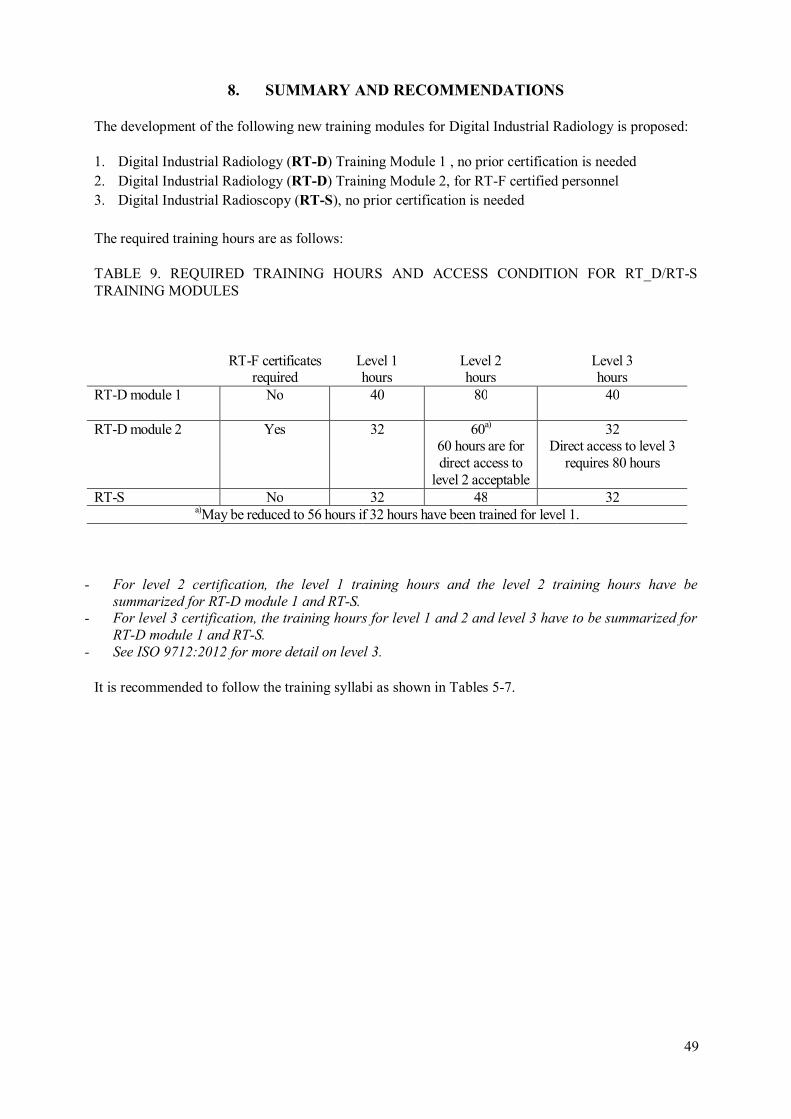
49
8. SUMMARY AND RECOMMENDATIONS
The development of the following new training modules for Digital Industrial Radiology is proposed:
1. Digital Industrial Radiology (RT-D) Training Module 1 , no prior certification is needed
2. Digital Industrial Radiology (RT-D) Training Module 2, for RT-F certified personnel 3. Digital Industrial Radioscopy (RT-S), no prior certification is needed
The required training hours are as follows:
TABLE 9. REQUIRED TRAINING HOURS AND ACCESS CONDITION FOR RT_D/RT-S TRAINING MODULES
- For level 2 certification, the level 1 training hours and the level 2 training hours have be
summarized for RT-D module 1 and RT-S. - For level 3 certification, the training hours for level 1 and 2 and level 3 have to be summarized for
RT-D module 1 and RT-S.
- See ISO 9712:2012 for more detail on level 3.
It is recommended to follow the training syllabi as shown in Tables 5-7.
RT-F certificates
required Level 1 hours
Level 2 hours
Level 3 hours
RT-D module 1
No 40 80 40
RT-D module 2 Yes 32 60a) 60 hours are for direct access to
level 2 acceptable
32 Direct access to level 3
requires 80 hours
RT-S No 32 48 32 a)May be reduced to 56 hours if 32 hours have been trained for level 1.

Required equipment for RT-D:
TABLE 10. REQUIRED HARDWARE FOR RT-D/RT-S TRAINING (WITHOUT VIRTUAL TRAINING OPTION)
- Optionally, for RT-D Training Modules 1 and 2 film digitization technology is recommended.
- RT-D training can also be performed, if only CR or DDA technology is available and one missing technology is trained with virtual training software.
- ISO/ TR 25108 [9] shall be considered. It requires furthermore:
• a range of image quality indicators (IQI);
• lead letters and numbers;
• masking materials as blocking-off compounds and/or liquids;
• copper and lead filters;
• radiation monitor;
• stepped blocks for making exposure curves;
• caliper or other device for measuring material thickness
X-Ray source and/or
Gamma source
Radiation measure
technique and bunker or
X-Ray cabin
Computed
radiography
Digital Detector
Array
X-ray image
intensifier
X-ray fluoroscope
Personal computer
Viewer software
RT-D Training module 1
X X X X X X
RT-D Training module 2
X X X X X X
RT-S X X X or → X or → X X X
50

51
Required number of examination questions for RT-D training:
TABLE 11. REQUIRED NUMBER OF EXAMINATION QUESTIONS FOR RT-D/RT-S EXAMINATION
For certification in level 3 additionally a
• basic examination in at least four main NDT methods (60 questions) is required and (35
questions) in material science, process technology and certification systems as well as the
practical level 2 examination.
• Drafting of one or more NDT procedures in the relevant sector. The applicable codes,
standards, specifications and procedures shall be available to the candidate.
• See ISO 9712:2012 for more detail on level 3.
Required number of practical tests for examination:
TABLE 12. REQUIRED PRACTICAL EXAMINATION TESTS FOR RT-D/RT-S EXAMINATION
General level 1+2 Specific level 1+2 Method level 3 Application level 3
RT-D
40 30 30 20
RT-S
40 30 30 20
Practical exposure of weldments
Practical exposure of
castings
Viewing and evaluation of
digital radiographs of
welds
Viewing and evaluation of
digital radiographs of castings
Viewing and evaluation of
digital radiographs of corroded pipes
RT-D
Level 1 + 2 1 exposure
Level 1 + 2 1 exposure
Level 2 8 dig. images
Level 2 8 dig. images
Level 2 8 dig. images
RT-S
Level 1 + 2 1 exposure
Level 1 + 2 1 exposure
Level 2 12 dig. images
Level 2 12 dig. images
-
• The Table 12 is related to the certification of an industrial sector (e.g. “Pre- and in-service
testing”). The certification board may request 1 additional exposure of a tube or pipe for RT-D
and increase the number of digital images for the examination to 12 per product sector, if certifying of separate product sectors is required.
• For certification in level 2 only one practical exposure needs to be performed for certified
level 1 personnel in the level 2 practical examination.
• For certification in level 2 the candidates have to write an instruction for level 1 operators in
the relevant product sectors for examination.
• For certification in level 1 or 2 one practical exposure (weld or casting) can be performed by a
virtual simulation tool upon agreement of the certification board and its auditing organization. Candidates shall perform at least one practical exposure in the examination.
• For certification in level 3 the candidates have to
o prove the successful level 2 practical examination and to
o write a procedure in the relevant product sectors for examination.
• See ISO 9712:2012 for more detail on level 3 examination.
Required experience times:
Required experience times are discussed in clause 7.1 and listed in Table 8. It is recommended to require additional 1/3 of the RT-D module 1 experience times for RT-F certified personnel for the RT-D certification (Table 8). For certification in level 2 the experience time of level 1 and 2 is required. For certification in level 3 the experience time of level 2 and 3 is required. Reductions are possible; see ISO 9712:2012 for more detail.
52

53
9. CONCLUSION ON PRIORITY FOR INTRODUCTION OF RT-D TRAINING
MODULES
The following priority is recommended for the order of training courses to be developed by IAEA:
- RT-D module 2, level 2: Training of certified RT-F 2 and/or RT-F 3 personnel in RT-D, level 2, seems to be of highest interest in the NDT community for training and certification of
radiographic operators changing from film radiography to digital radiography level 2 (“film
replacement”). The training course allows the direct access to RT-D level 2 without level 1 training and examination. RT-D level 3 personnel need the pre-knowledge of the level 2
training course and the RT-D, level 2, practical examination for certification.
- RT-D module 2 (level 1 and level 2) training is of interest for industry in the long term, since
companies will need also more level 1 operators in the future, after achieving a minimum
number of level 2 operators.
- RT-S (level 1 and level 2) is of importance for industries with serial part production (e.g. fine
castings). In most cases complex radioscopic devices need to be operated. The training classes should be combined with training of the specific devices, installed by the companies. Such
training is typically conducted together with the manufacturer and/or the final user of the equipment.
- RT-CT: Computed Tomography is currently not widely applied in industry. CT devices are
relatively complex units and need specific training on the CT equipment by the manufacturer. It is not likely that operators will already be trained in RT-F. Therefore, a specialized CT
training module should be developed together with manufacturers on the basis of an extended RT-S training course.
- Additional training is required in 3D-image processing and measurement tools in 3
dimensions. The RT-S course supplies the basic knowledge on CT, but no specialized training of manufacturer specific devices. No need is seen to extend the training activities for CT
currently and it is recommended that this training should be equipment specific training rather
than general training.
- RT-D: General RT-D module 1 training, without prior RT-F training, is likely to be required
in the longer term if film radiography loses its relative importance with respect to RT-D. Therefore, the full RT-D training course at this stage is not recommended as a replacement for
RT-F training. E.g., the German Society for NDT and its Radiology Committee has decided to
postpone the development of a complete RT-D module 1 training course. - It is recommended instead, to replace the RT-D, level 2 training course with a new RT, level 3
training course with integrated level 3 training in RT-F and RT-D. The German society has
finalized a new RT, level 3 course (80 hours), which integrates film (RT-F) and digital detectors (RT-D) including CT as well. Initial discussions with ASNT indicate that ASNT will
also consider the development of a common level 3 training course with film and digital techniques integrated. As a result, it is recommended to IAEA and Member States to consider
an integrated level 3 training course (RT, level 3) instead of a separated RT-D, level 3 training
course.


55
REFERENCES
[1] ISO 9712:2005, Non-Destructive Testing -- Qualification And Certification Of Personnel, International Standardization Organization, Third edition, Corrected version (2005).
[2] ISO 9712:2012, Non Destructive Testing -- Qualification And Certification Of NDT Personnel - General Principles, International Standardization Organization, Fourth edition (2012).
[3] EN 473 – Non-Destructive Testing - Qualification And Certification Of NDT Personnel - General Principles, International Standardization Organization, edition (2008).
[4] prEN 473 – Non-Destructive Testing - Qualification And Certification Of NDT Personnel - General Principles, 2009-10, revised EN 473:2008/prA1:2009,.
[5] INTERNATIONL ATOMIC ENERGY AGENCY-TECDOC-628/REV.2, Training Guidelines in Non-destructive Testing Techniques, edition (2008).
[6] Guidelines For The Use Of Digital Detector Arrays And Computed Radiology For Aerospace Casting Inspections, Developed Under The Metals Affordability Initiative (Mai) Program “Use Of Digital Radiography For Final Acceptance Of Aerospace Castings”, Contract #FA8650-08-2-5249 (2011).
[7] RODRIGUEZ R., ROMERO E., Leonardo Da Vinci, European Training Programme For The Qualification Of Ndt Personnel, Radiography (level 1, 2, 3) (2009).
[8] ISO/TR 25107, Non-Destructive Testing -- Guidelines For Ndt Training Syllabuses (2006). [9] ISO/TR 25108, Non-Destructive Testing -- Guidelines For Ndt Personnel Training Organizations
(2006). [10] EWERT U., ZSCHERPEL U., Lecture Script For The Iaea/Rca Regional Training Course On
Digital Industrial Radiology And Computed Tomography Applications In Industr, Istanbul, Turkey, 13 – 22 May (2013).
[11] EWERT U., ZSCHERPEL U., Presentations For The Iaea/Rca Regional Training Course On Digital Industrial Radiology And Computed Tomography Applications In Industry”, Istanbul, Turkey, 13 – 22 May (2013).
[12] ALEKSEYCHUK, O., “ISee!”, “The Radiographic Image Analysis Software”, BAM VIII.3, http://www.kb.bam.de/ic.
[13] JAENISCH, G.-R., BELLON, C., EWERT, U., “aRTist” – “Analytical Rt Inspection Simulation Tool For Industrial Application Proceedings of the 17th World Conference on Non-Destructive Testing”, Shanghai, China, International Committee on NDT, CDrom paper 64 (2008).
[14] BAVENDIEK, K., HEIKE, U., MEADE, W. D., ZSCHERPEL, U., EWERT, U., “New Digital Radiography Procedure Exceeds Film Sensitivity Considerably In Aerospace Application”, 9th ECNDT, Berlin, 25.-29.9.2006, Proceedings CD, NDT.NET publication, http://www.ndt.net/article/ecndt2006/doc/Th.3.2.1.pdf.
[15] EWERT, U., ZSCHERPEL, U., BAVENDIEK, K., “Digitale Radiologie In Der Zfp - Belichtungszeit Und Kontrastempfindlichkeit - Der Äquivalenzwert Zur Optischen Dichte Des Films”, DGZfP-Jahrestagung, Rostock, 2.-4.5.2005.
[16] EWERT, U., ZSCHERPEL, U., BAVENDIEK, K., “Replacement Of Film Radiography By Digital Techniques And Enhancement Of Image Quality”, annual conference of Indian NDT society, Kolkata, 4.-6.12.2005, V.S. Jain-Lecture.
[17] EWERT, U., ZSCHERPEL, U., BAVENDIEK, K., “Strategies For Film Replacement In Radiography - A Comparative Study”, Panndt , 22-26 Oct. 2007, Buenos Aires, Argentina.
[18] EWERT, U., ZSCHERPEL, U., BAVENDIEK, K., “Strategies For Film Replacement In Radiography - Films And Digital Detectors In Comparison”, WCNDT, Shanghai, China (2008).
[19] EWERT, U., BAVENDIEK, K., ROBBINS, J., ZSCHERPEL, U., BUENO, C., GORDON, T., MISHRA, D., New Compensation Principles For Enhanced Image Quality In Industrial Radiology With Digital Detector Array, Materials Evaluation 68 2 (2010) 163-168.
[20] BAVENDIEK, K., HEIKE, U. KOSANETZKY, J. M., EWERT, U. ZSCHERPEL, U., Best Energy Selection For Different Applications With Ddas - From 20kev To 600kev, Materials Evaluation, 69 7 (2011).
[21] ROSE, A., A Unified Approach To The Performance Of Photographic Film, Television Pickup Tubes And The Human Eye, J. of the Society of Motion Picture Engineers (SMPTE) 47 4 (1946) 273-294.

[22] ROSE, A., The Sensitivity Performance Of The Human Eye On An Absolute Scale, J. Opt. Soc. Am. 38 (1948) 196-208.
[23] ROSE, A., “Television Pickup Tubes And The Problem Of Vision, In Advances In Electronics And Electron Physics”, L. Marton, ed., 1 Academic, New York (1948) 131-166.
[24] EWERT, U., HEYNE, K., ZSCHERPEL, U., JECHOW, M., BAVENDIEK K., “Optimum Exposure Conditions For Computed Radiography Depending On Fixed Pattern Noise And Efficiency Of Imaging Plate – Scanner Systems”, AIP Conference Proceedings 1335 of 37th Annual Review of Progress in Quantitative Nondestructive Evaluation, QNDE, San Diego (2010) ISBN 978-0-7354-0888-3.
[25] EWERT, U., ZSCHERPEL, U., HEYNE, K., JECHOW, M., BAVENDIEK, K., Image Quality In Digital Industrial Radiology, Materials Evaluation, 70 8 (2011) 955-964.
56

57
ABBREVIATIONS
RT Radiographic testing RT-D Radiographic testing – Digital technique
RT-F Radiographic testing – Film Technique
RT-S Radiographic testing – Radioscopy with training time ≥ 50% of level 2 of RT-D RT-CT Radiographic testing – Computed Tomography
UT Ultrasonic testing VT Visual testing
PT Penetrant testing
MT Magnetic testing CR Computed Radiography (also known as RT with phosphor imaging plates)
DDA Digital Detector Array (also known as flat panel detector)
LDA Line Detector Array DIR Digital Industrial Radiography
NDT Non Destructive Testing DGZfP German Society for NDT
ISNT Indian Society of NDT
ICNDT International Committee for NDT ISO International Standardization Organization
IQI Image Quality Indicator ASTM American Society for Testing and Materials
ASME American Society of Mechanical Engineers


59
APPENDIX I. AVAILABLE IAEA TRAINING LECTURES FOR RT-D MODULE 2
The IAEA training on digital industrial radiology is basically designed as a training course for level 2 and may also be used for level 3 training to be conducted within a week. It needs to be updated considering the recently published standards on RT-D since 2010 and the corresponding exercises.
The PowerPoint lectures and the training booklet [9, 10] were developed for IAEA in 2009. The training book and the presentations cover the RT-D Module 2, level 2, and training with direct access to level 2 for RT-F level 2 certified personnel.
The training booklet has the following Table of content:
L 01 Physical Basics of the X-ray Technology
1.1 Introduction 2 1.2 Generation of X-rays 2 1.3 Parameter adjustment on the X-ray generator operating console 4 1.3.1 Choice of the tube current 4 1.3.2 Choice of the accelerating potential (tube voltage) 4 1.4 Attenuating the radiation 5 1.4.1 Attenuation of radiation by photo absorption 5 1.4.2 Attenuation by scattering 5 1.4.3 Law of the attenuation of X-rays 7 1.5 Hardening by pre-filtering 8
L 02 Radiation Contrast and Imaging Requirements
2.1 Introduction 2 2.2 Quantitative considerations 2 2.3 Noise 6 2.4 Focal spot of X-ray generators (focus) 9 2.4.1 Ideal imaging geometry 10 2.4.2 Real imaging geometry 11 2.5 Law of the squared distances 15
L 03 Standardisation I
3.1 Introduction 2 3.2 Basic standard for radiography EN 444 2 3.2.1 Contrast 2 3.2.2 Graininess / internal unsharpness ui 3 3.2.3 Unsharpness 3 3.3 Radiographic inspection of weld seams EN 1435 5 3.4 Measurement of the focal spot size according to EN 12543 5 3.4.1 EN12543-part 1 „scanning-procedure“ 6 3.4.2 EN 12543 – part 2 „pinhole“ 9 3.4.3 EN 12543 – part 3 „slit collimator“, part 4 „edge method“ 9 3.4.4 EN 12543 – part 5 „wire cross“ 10 3.5 Energy limits of X-ray generators according to EN 12544 10 3.5.1 EN 12544 – part 3 „spectrometry“ 10 3.5.2 EN 12544 – part 1 „voltage divider method“ 12 3.5.3 EN 12544 – part 2 „Filter method“ 12 3.6 ASTM-rules and standards (USA) as compared to the EN-standards 13
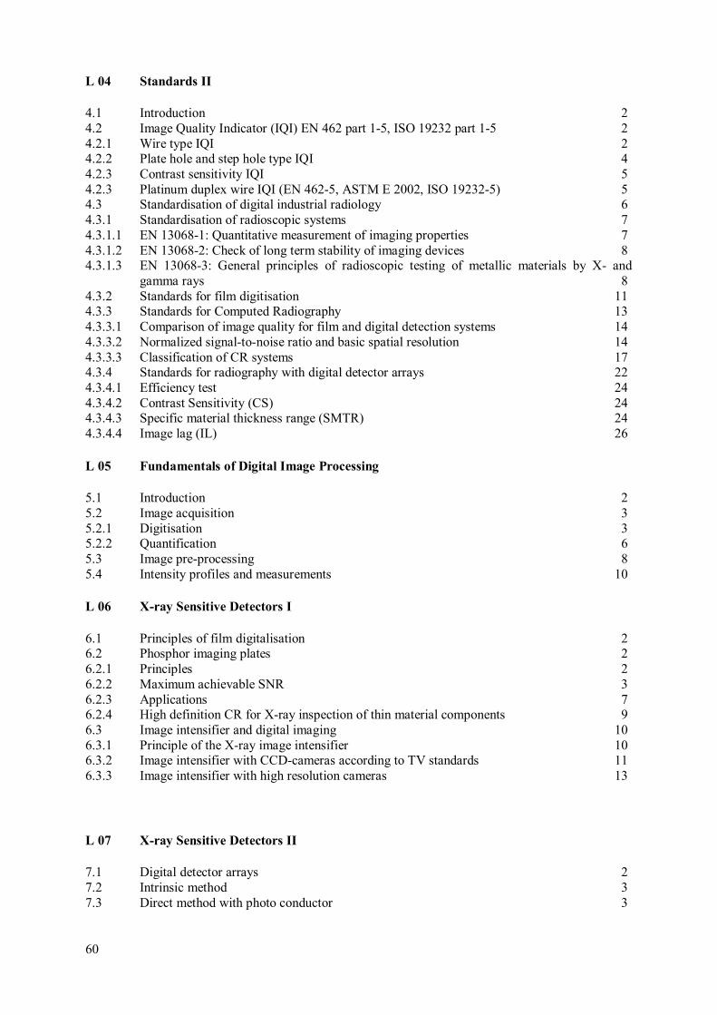
L 04 Standards II
4.1 Introduction 2 4.2 Image Quality Indicator (IQI) EN 462 part 1-5, ISO 19232 part 1-5 2 4.2.1 Wire type IQI 2 4.2.2 Plate hole and step hole type IQI 4 4.2.3 Contrast sensitivity IQI 5 4.2.3 Platinum duplex wire IQI (EN 462-5, ASTM E 2002, ISO 19232-5) 5 4.3 Standardisation of digital industrial radiology 6 4.3.1 Standardisation of radioscopic systems 7 4.3.1.1 EN 13068-1: Quantitative measurement of imaging properties 7 4.3.1.2 EN 13068-2: Check of long term stability of imaging devices 8 4.3.1.3 EN 13068-3: General principles of radioscopic testing of metallic materials by X- and
gamma rays 8 4.3.2 Standards for film digitisation 11 4.3.3 Standards for Computed Radiography 13 4.3.3.1 Comparison of image quality for film and digital detection systems 14 4.3.3.2 Normalized signal-to-noise ratio and basic spatial resolution 14 4.3.3.3 Classification of CR systems 17 4.3.4 Standards for radiography with digital detector arrays 22 4.3.4.1 Efficiency test 24 4.3.4.2 Contrast Sensitivity (CS) 24 4.3.4.3 Specific material thickness range (SMTR) 24 4.3.4.4 Image lag (IL) 26
L 05 Fundamentals of Digital Image Processing
5.1 Introduction 2 5.2 Image acquisition 3 5.2.1 Digitisation 3 5.2.2 Quantification 6 5.3 Image pre-processing 8 5.4 Intensity profiles and measurements 10
L 06 X-ray Sensitive Detectors I
6.1 Principles of film digitalisation 2 6.2 Phosphor imaging plates 2 6.2.1 Principles 2 6.2.2 Maximum achievable SNR 3 6.2.3 Applications 7 6.2.4 High definition CR for X-ray inspection of thin material components 9 6.3 Image intensifier and digital imaging 10 6.3.1 Principle of the X-ray image intensifier 10 6.3.2 Image intensifier with CCD-cameras according to TV standards 11 6.3.3 Image intensifier with high resolution cameras 13
L 07 X-ray Sensitive Detectors II
7.1 Digital detector arrays 2 7.2 Intrinsic method 3 7.3 Direct method with photo conductor 3
60

61
7.4 Scintillator method 5 7.5 CMOS digital detector arrays 8 7.6 A radioscopic system with a digital detector array 10 7.7 Compensation principles 10 7.7.1 General remarks 11 7.7.2 Compensation Principle I 11 7.7.3 Compensation principle II 14 7.7.4 Compensation Principle III 16 7.7.5 References 18
L 08 Image Processing Systems - Design
8.1 Hardware-setup of an actual image processing system 2 8.2 Image signal interfaces 3 8.3 Bus system 3 8.4 Main memory 4 8.5 Permanent memory 4 8.6 CPU 4 8.7 Image presentations 5 8.8 Image archiving 7 8.9 Image formats 8
L 09 Image Acquisition and Pre-processing
9.1 Image acquisition 2 9.2 Image specification 2 9.2.1 Mean and standard deviation 2 9.2.2 Histogram 3 9.3 Noise suppression 5 9.3.1 Improving the signal-to-noise ratio by digital image integration 5 9.3.2 Improving the signal-to-noise ratio depending on exposure time and dosage 7 9.4 Look-up Table (LUT) 7 9.4.1 Input - LUT 7 9.4.2 Output - LUT 9 9.5 Enlargement of digital images 10
L 10 Filtering Image Data
10.1 Introduction 2 10.2 Point and matrix operations 2 10.3 Practical realisation of a filter operation 2 10.4 Various filter templates 5 10.4.1 Low pass filter 5 10.4.2 High pass filter 6 10.4.3 Band pass filter 7 10.4.4 Effect of a filter in the frequency domain 8 10.5 The median filter 10

L 11 Application of Digital Filters
11.1 Filters for the suppression of noise 2 11.1.1 Low pass filters 2 11.1.2 Median filters 3 11.2 Filters to emphasise structures 3 11.2.1 Sharpening filters 4 11.2.2 Pseudo-plast filters (pseudo-3D exhibiting) 5 11.3 Filters to extract edges and structures 6 11.3.1 The Sobel operator 7 11.3.2 The Laplace operator 8 11.3.3 The band pass operator 10
L 12 Measuring Functions within the Image
12.1 Measuring lengths, areas and intensities 2 12.1.1 Calibration of measurements 2 12.2 Measuring of lengths 2 12.3 Measuring of areas 3 12.4 Measuring of intensities 4 12.4.1 Calibration of intensity measurements 4 12.4.2 Accomplishing of intensity measurements 5 12.5 Determination of depth by stereo technique 6
L 13 Evaluation of Digital Image Data
13.1 Requirements for the quality of digital images 2 13.2 Documentation 5 13.3 Evaluation according to Rules and Standards 6 13.3.1 Reference catalogues: ASTM E155 and E 2422 6 13.3.2 Evaluation of weld seam irregularities according to ISO 5817 8
L 14 Compilation of a Written Procedure
14.1 Preface 2 14.2 Purpose of a written procedure 2 14.3 Procedure of compiling a written procedure 2 14.4 Design and content of an inspection instruction 3 14.5 Meaningful structure of an inspection instruction 4 14.6 Written procedure (short schedule format, testing record) 5
L 15 Automatic Image Evaluation
15.1 Semi automatic and automatic image evaluation 2 15.2 Methods and mode of operation of the automatic image evaluation 2 15.3 Flow of a semi automatic image evaluation 4 15.4 Automatic evaluation of weld seams 5 15.4.1 Limits of the automatic weld seam evaluation 5 15.5 Automatic image evaluation of cast components 7 15.5.1 Requirements for the fully automatic evaluation of cast components 8 15.5.2 Flow of the fully automatic cast component inspection 8 15.5.3 The use of the reference image technology 9 15.5.4 Procedure of the Automatic Defect Recognition (ADR) 10 15.5.5 Problems encountered with the automatic defect recognition (ADR) 12
62

63
15.6 Differences between visual and automatic inspection 13 15.6.1 Application areas of the visual and automatic inspection 14 15.7 Process optimisation by X-ray inspection 15
L 16 Computed Tomography
16.1 Introduction 2 16.2 Data acquisition 3 16.2.1 Two-dimensional computed tomography 3 16.2.2 Three-dimensional CT 4 16.2.3 Requirements for the setup of a CT system 5 16.2.4 Accomplishing a measurement 6 16.3 Noise 6 16.4 Artefacts 7 16.4.1 Definition of the term 7 16.4.2 Reasons for artefacts 7 16.5 Visualisation and evaluation 9 16.6 Fields of application 11
Example of a testing record
Written exercises are available (developed for one week training at 4 days after setup of
computers at first day)
- Image Acquisition with Computed Radiography
- Contrast Optimization and Segmentation
- Measurement of Distances and Calibration
Software is available
- Image viewer software ISee (free demo licence [11]) and pen-drive or DVD with digital images
- Simulation software aRTist (licensed for limited time [12]) can be distributed for
training issues.
Hardware is available: e.g. low budget fluoroscope (IAEA construction guidebook under
reference ‘’ Design, Development and Optimization of a low-cost System for Digital Industrial
Radiology ‘’ Radiation Technology Reports n°2, ISBN number: 978-92-0-129310-7).
Following Updates are required
- Measurements of exposure diagrams for CR
- DDA practice, measurement of CNR for plate holes
- DDA quality assurance ASTM E 2737
- Exercise with standard practice of ISO 17636-2
- Exercise with standard practice ASTM BPVC S. V article 2
- Exercise with viewing of digital reference catalogues

INFORMATIVE REFERENCE TO ISO 9712:2012 ON REQUIRED TRAINING HOURS
Table A1.1 shows the required number of training hours and the conditions for the reduction of the training time, down to 50%. RT is split in RT-F and RT-D in extension to the current Table 2 of ISO 9712:2012. All extensions are highlighted.
TABLE A1.1. MINIMUM TRAINING HOURS AS REQUIRED BY ISO 9712:2012 (EQUIVALENT TO TECDOC-628/REV.2 FOR RT-F), WITH EXTENSIONS BY DIFFERENT RT TECHNIQUES
INFORMATIVE BREAK DOWN OF TRAINING HOURS FOR RT-D/S
The Tables 5-6 show the coarse break down of training hours. The following Tables A1.2 – A1.4 show a proposed fine-tuned breakdown for the training hours. This may be modified depending on the need of the national training centers.
NDT Method Level 1
hours Level 2 hours
Level 3 hours
AT 40 64 48 ET
40 48 48
LT 24 24
32 40
32 40
B - pressure method C – Tracer gas method
MT 16 24 24 PT 16 24 24 ST 16 24 20 TT
40 80 40
RT RT-F 40 80 40 a,b)RT-D
40 80 40
UT 40 80 40 VT 16 24 24 - a) Training duration may be reduced by up to 50 %:
- - for RT-D training of personnel certified in the same or higher RT-F level - in only one technique as training using only Radioscopy (RT-S) is sought
b) 60 hours are required for direct access to level 2 without level 1 training and examination
of personnel certified in the same or higher RT-F level.
- NOTE: For RT, training hours do not include radiation safety training.
64
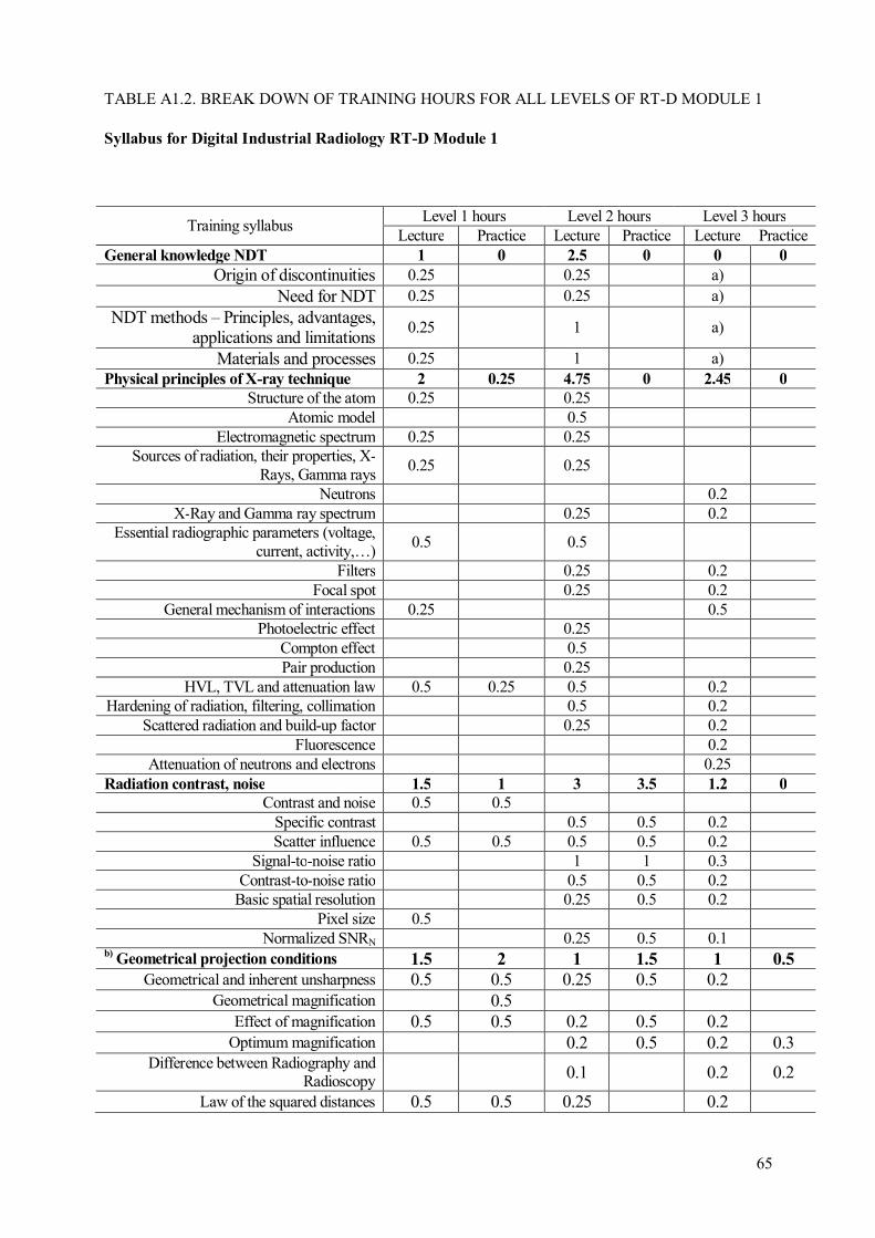
65
TABLE A1.2. BREAK DOWN OF TRAINING HOURS FOR ALL LEVELS OF RT-D MODULE 1
Syllabus for Digital Industrial Radiology RT-D Module 1
Training syllabus Level 1 hours Level 2 hours Level 3 hours
Lecture Practice Lecture Practice Lecture Practice General knowledge NDT 1 0 2.5 0 0 0
Origin of discontinuities 0.25 0.25 a)
Need for NDT 0.25 0.25 a)
NDT methods – Principles, advantages, applications and limitations
0.25 1 a)
Materials and processes 0.25 1 a) Physical principles of X-ray technique 2 0.25 4.75 0 2.45 0
Structure of the atom 0.25 0.25 Atomic model 0.5
Electromagnetic spectrum 0.25 0.25 Sources of radiation, their properties, X-
Rays, Gamma rays 0.25 0.25
Neutrons 0.2 X-Ray and Gamma ray spectrum 0.25 0.2
Essential radiographic parameters (voltage, current, activity,…)
0.5 0.5
Filters 0.25 0.2 Focal spot 0.25 0.2
General mechanism of interactions 0.25 0.5 Photoelectric effect 0.25
Compton effect 0.5 Pair production 0.25
HVL, TVL and attenuation law 0.5 0.25 0.5 0.2 Hardening of radiation, filtering, collimation 0.5 0.2
Scattered radiation and build-up factor 0.25 0.2 Fluorescence 0.2
Attenuation of neutrons and electrons 0.25 Radiation contrast, noise 1.5 1 3 3.5 1.2 0
Contrast and noise 0.5 0.5 Specific contrast 0.5 0.5 0.2 Scatter influence 0.5 0.5 0.5 0.5 0.2
Signal-to-noise ratio 1 1 0.3 Contrast-to-noise ratio 0.5 0.5 0.2
Basic spatial resolution 0.25 0.5 0.2 Pixel size 0.5
Normalized SNRN 0.25 0.5 0.1 b)
Geometrical projection conditions 1.5 2 1 1.5 1 0.5
Geometrical and inherent unsharpness 0.5 0.5 0.25 0.5 0.2 Geometrical magnification 0.5
Effect of magnification 0.5 0.5 0.2 0.5 0.2 Optimum magnification 0.2 0.5 0.2 0.3
Difference between Radiography and Radioscopy 0.1 0.2 0.2
Law of the squared distances 0.5 0.5 0.25 0.2
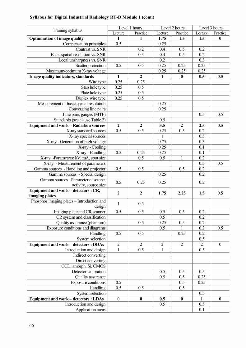
Training syllabus Level 1 hours Level 2 hours Level 3 hours
Lecture Practice Lecture Practice Lecture Practice Optimisation of image quality 1 1 1.75 1.5 1.5 0
Compensation principles 0.5 0.25 Contrast vs. SNR 0.2 0.4 0.5 0.2
Basic spatial resolution vs. SNR 0.3 0.4 0.5 0.2 Local unsharpness vs. SNR 0.2 0.3
Scatter protection 0.5 0.5 0.25 0.25 0.25 Maximum/optimum X-ray voltage 0.25 0.25 0.25
Image quality indicators, standards 1 2 1 0 0.5 0.5
Wire type 0.25 0.25 Step hole type 0.25 0.5 Plate hole type 0.25 0.5
Duplex wire type 0.25 0.5 Measurement of basic spatial resolution 0.25
Converging line pairs 0.25 Line pairs gauges (MTF) 0.5 0.5
Standards (see clause Table 2) 0.5 Equipment and work – Radiation sources 2 2 3.5 2 2.5 0.5
X-ray standard sources 0.5 0.5 0.25 0.5 0.2 X-ray special sources 1 0.5
X-ray - Generation of high voltage 0.75 0.3 X-ray - Cooling 0.25 0.1
X-ray - Handling 0.5 0.25 0.25 0.1 X-ray -Parameters: kV, mA, spot size 0.5 0.5 1 0.2
X-ray - Measurement of parameters 0.5 0.5 Gamma sources - Handling and projector 0.5 0.5 0.5 0.2
Gamma sources - Special design 0.25 0.2 Gamma sources -Parameters: isotope,
activity, source size 0.5 0.25 0.25 0.2
Equipment and work – detectors : CR,
imaging plates 2 2 1.75 2.25 1.5 0.5
Phosphor imaging plates – Introduction and design
1 0.5
Imaging plate and CR scanner 0.5 0.5 0.5 0.5 0.2 CR system and classification 0.5 0.2 Quality assurance (phantom) 0.5 0.25 0.5 0.2
Exposure conditions and diagrams 0.5 1 0.2 0.5 Handling 0.5 0.5 0.25 0.2
System selection 0.5 Equipment and work – detectors : DDAs 2 2 2 2 2 0
Introduction and design 1 0.5 1 0.5 Indirect converting
Direct converting CCD, amorph. Si, CMOS
Detector calibration 0.5 0.5 0.5 Quality assurance 0.5 0.5 0.25
Exposure conditions 0.5 1 0.5 0.25 Handling 0.5 0.5 0.5
System selection 0.5 Equipment and work – detectors : LDAs 0 0 0.5 0 1 0
Introduction and design 0.5 0.5 Application areas 0.1
Syllabus for Digital Industrial Radiology RT-D Module 1 (cont.)
66

67
Training syllabus Level 1 hours Level 2 hours Level 3 hours
Lecture Practice Lecture Practice Lecture Practice Comparison to DDAs 0.1
Quality assurance Exposure conditions 0.1
Handling System selection 0.2
Equipment and work – detectors :
intensifiers, fluoroscope 0 0 1.25 0.25 1 0
Introduction and design 0.5 0.1 Application areas 0.25 0.1
Comparison to DDAs 0.25 0.1 Quality assurance 0.25 0.1
Exposure conditions 0.25 0.1 Handling
System selection 0.5 Equipment and work – detectors : film
digitization 0 0 0.5 0 0.5 0
Scanner design (camera based, line scanners, laser scanners)
0.25 0.1
Quality assurance (EPRI test film) 0.25 0.1 Handling, archiving 0.1
System selection 0.1 Classification 0.1
Data acquisition, detector calibration 0 0 2 2 1 1 A/D interface 0.25 0.2
Computer structure ( Processor, memory, bus, disk, Load and save of digital images,
image formats) 0.25 0.5 0.3
Image integration (on-chip, in memory, optimum gain and latitude settings,
accumulation vs. integration) 1.5 1.5 0.5 1
Digital image processing (total) 2 2.75 7 7 3.1 2.5
Image structure, quantisation (bits and bytes)
0.25 0.5 0.25
Basic operation (picture element – pixel, gray value)
0.75 1 0.5 0.25
Point operations (contrast, brightness, gamma correction, histogram, LUT)
1 1 1 1 0.25 0.5
Matrix operations, filter (smoothing, improvement of SNR, high pass, gradient,
edge enhancement, line extraction, median) 3 3 1.5 1
Measurement tools (calibration, line profile, measurement of flaw, length, measurement
of areas and depth) 0.75 1 2 0.35 1
Correction of raw data (linearization, LUT correction, bad pixel interpolation)
1 1 0.5
Standards 1 0 3 1.5 3 0 Guides 0.5 1 0.5
Qualification of sources 1 0.5 0.5 General qualification of detectors 1
User qualification of detectors 0.5 1 1 1 See Table 2
Defectology, digital catalogues 0.5 0.5 1 2.5 0.75 1
Syllabus for Digital Industrial Radiology RT-D Module 1 (cont.)

Training syllabus Level 1 hours Level 2 hours Level 3 hours Lecture Practice Lecture Practice Lecture Practice
- General welding (ISO 6520) and casting defects (ASTM casting
catalogues) 0.5 0.5 0.5 0.5 0.25
- Evaluation of welding: IIW catalogue
- ISO 5817 0.5 1 0.25 0.5
- Evaluation of casting: ASTM
catalogues 1 0.25 0.5
- corrosion Automated image interpretation 0 0 1 1 1 0
- Principles 0.25 0.3 - Binarisation 0.5 0.5 0.4 - Measurement of dimensions 0.25 0.5 0.3
b) Special techniques, computed
tomography 0 0 1 1 1.5 0.5
- Stereoradiography 0.5 0.25 - Laminography 0.25 - Computed tomography 0.5 1 0.5 0.5 - Inspection geometry - 2D vs. 3D
- Reconstruction principles - Filtered backprojection
- Applications - Requirements and limit of method - Special CT techniques 0.5
Applications, standard practices and
evaluation 2 3 2.5 6 2 2.5
- Welds (standard practices with different exposure geometries,
interpretation of digital images, digital processing of images,
evaluation of flaws with
dimensions measurement, written instruction/procedure)
1 1 1 3 1 1
Syllabus for Digital Industrial Radiology RT-D Module 1 (cont.)
68

69
a) In addition to the above 40 hours a general knowledge common core course for level 3 (applicable to all NDT methods) is recommended, which shall be successfully completed only once.
b) More hours are recommended for RT-CT related training.
c) National laws and regulations are to be considered for training on radiation safety and handling of radiation sources. Radiation safety may be trained in separated courses, or training hours should be considered to be additional to those of the syllabus requirements (see TECDOC-628/Rev.2).
Training syllabus Level 1 hours Level 2 hours Level 3 hours Lecture Practice Lecture Practice Lecture Practice
- Castings ( standard practices with different exposure geometries,
interpretation of digital images,
digital processing of images, evaluation of flaws with
dimensions measurement, use of catalogues, written
instruction/procedure)
1 1 1 2 0.5 1
- Corrosion wall thickness measurement (tangential RT,
double wall RT, calibration of digital images, measurement of
thickness, written
instruction/procedure)
1 1 0.5
- Others… 0.5 0.5 Written procedure/ instructions 0 0 1 2 0 2
Welds 0.5 0.75 0.75 Castings 0.5 0.75 0.75
Corrosion wall thickness measurement 0.5 0.5 c)Radiation protection
Extra training course depending on national regulations recommended
1 1 1 1 1 0
Total 20.5 20 43 37 28.5 11.5
40 80 40
Syllabus for Digital Industrial Radiology RT-D Module 1 (cont.)

TABLE A1.3. BREAK DOWN OF TRAINING HOURS FOR ALL LEVELS OF RT-D MODULE 2
Training syllabus Level 1 hours Level 2 hours Level 3 hours
Lecture Practice Lecture Practice Lecture Practice General knowledge NDT 0 0 0 0 0 0
- Origin of discontinuities a)
- Need for NDT a)
- NDT methods, principles,
advantages, applications and
limitations
a)
- Materials and processes a)
Physical principles of X-ray technique 0.9 0.2 1 0 1.4 0 - Structure of the atom 0.1 0.1
- Atomic model 0.1 - Electromagnetic spectrum 0.1
- Sources of radiation, their properties, X-rays, gamma rays
0.25 0.1
- Neutrons 0.2 - X-ray and gamma ray spectrum 0.1 0.1 - Essential radiographic parameters
(voltage, current, activity) 0.1 0.1 0.1
- Filters 0.1 0.1
- Focal spot 0.1 0.1 - General mechanism of interactions
(photoelectric effect, Compton effect, pair production)
0.25 0.2 0.3
- HVL, TVL and attenuation law 0.1 0.1 - Hardening of radiation, filtering,
collimation 0.1 0.2 0.1
- Scattered radiation and build-up factor
0.1
- Fluorescence 0.1 - Attenuation of neutrons and
electrons 0.1
Radiation contrast, noise 0.9 0 1.5 1.5 1.2 0
- Contrast and noise 0.5 - Specific contrast 0.25 0.2 - Scatter influence 0.15 0.25 0.2 - Signal-to noise ratio 0.25 0.5 0.3 - Contrast-to noise ratio 0.25 0.25 0.2 - Basic spatial resolution 0.25 0.5 0.2 - Pixel size 0.25 - Normalized SNRN 0.25 0.25 0.1
70
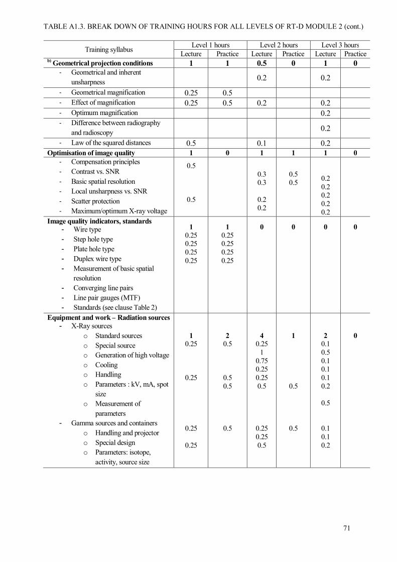
71
Training syllabus Level 1 hours Level 2 hours Level 3 hours Lecture Practice Lecture Practice Lecture Practice
b) Geometrical projection conditions 1 1 0.5 0 1 0
- Geometrical and inherent
unsharpness 0.2 0.2
- Geometrical magnification 0.25 0.5 - Effect of magnification 0.25 0.5 0.2 0.2 - Optimum magnification 0.2 - Difference between radiography
and radioscopy 0.2
- Law of the squared distances 0.5 0.1 0.2 Optimisation of image quality 1 0 1 1 1 0
- Compensation principles
- Contrast vs. SNR
- Basic spatial resolution
- Local unsharpness vs. SNR
- Scatter protection
- Maximum/optimum X-ray voltage
0.5
0.5
0.3 0.3
0.2 0.2
0.5 0.5
0.2 0.2 0.2 0.2 0.2
Image quality indicators, standards - Wire type
- Step hole type
- Plate hole type
- Duplex wire type
- Measurement of basic spatial resolution
- Converging line pairs
- Line pair gauges (MTF)
- Standards (see clause Table 2)
1
0.25 0.25 0.25 0.25
1
0.25 0.25 0.25 0.25
0
0
0
0
Equipment and work – Radiation sources
- X-Ray sources
o Standard sources
o Special source o Generation of high voltage
o Cooling o Handling
o Parameters : kV, mA, spot
size o Measurement of
parameters - Gamma sources and containers
o Handling and projector
o Special design o Parameters: isotope,
activity, source size
1 0.25
0.25
0.25
0.25
2 0.5
0.5 0.5
0.5
4 0.25
1 0.75 0.25 0.25 0.5
0.25 0.25 0.5
1
0.5
0.5
2 0.1 0.5 0.1 0.1 0.1 0.2
0.5
0.1 0.1 0.2
0
TABLE A1.3. BREAK DOWN OF TRAINING HOURS FOR ALL LEVELS OF RT-D MODULE 2 (cont.)

Training syllabus Level 1 hours Level 2 hours Level 3 hours Lecture Practice Lecture Practice Lecture Practice
Equipment and work – detectors : CR,
imaging plates
- Phosphor imaging plates,
introduction and design
- Imaging plate and CR scanner
- CR system and classification
- Quality assurance (phantom)
- Exposure conditions and diagrams
- Handling
- System selection
1.5
0.5
0.5
0.5
2
0.5
0.75
0.75
2
0.5 0.5 0.25 0.5 0.25
2
0.5
0.25 1
0.25
1
0.1 0.1 0.2 0.2 0.2 0.2
1
0.2 0.5
0.3
Equipment and work – detectors : DDAs
- Digital Detector Arrays (DDA)- Introduction and design
o Indirect converting
o Direct converting o CCD, amorph, Si, CMOS
- Detector calibration
- Quality assurance
- Exposure conditions
- Handling
- System selection
1.5
0.5
0.5 0.5
2
0.5
0.5
0.5 0.5
2
1
0.5 0.5
2
0.5 0.5 0.5 0.5
1.5
0.5
0.3 0.1
0.1 0.5
0.5
0.25 0.25
Equipment and work – detectors : LDAs
- Line Detector Arrays (LDAs)- Introduction and design
- Application areas
- Comparison to DDAs
- Quality assurance
- Exposure conditions
- Handling
- System selection
0
0
0.5 0.5
0
0.5 0.1
0.1 0.1 0.1
0.1
0
TABLE A1.3. BREAK DOWN OF TRAINING HOURS FOR ALL LEVELS OF RT-D MODULE 2 (cont.)
72

73
Training syllabus Level 1 hours Level 2 hours Level 3 hours
Lecture Practice Lecture Practice Lecture Practice Equipment and work – detectors :
intensifiers, fluoroscope
- Introduction and design
- Application areas
- Quality assurance
- Exposure conditions
- Handling
- System selection
- Comparison to DDAs
0.5
0.5
0
0.5
0.25
0.25
1
0.25 0.25 0.25 0.25
0.5
0.1 0.1 0.1
0.1 0.1
0
Equipment and work – detectors : film
digitization
- Scanner design o Camera based
o Line scanners
o Laser scanners
- Quality assurance (EPRI test film)
- Handling, archiving
- System selection
- Classification
0
0
0.5
0.25
0.25
0
0
0
Data acquisition, detector calibration
- A/D interface
- Computer structure
o Processor, memory, bus, disk
o Load and save of digital
images o Image formats
- Image integration o On chip integration
o In memory integration
o Optimum gain and latitude settings
o Accumulation vs. integration
0
0
1
0.25 0.25
0.5
1
1
1
0.3 0.2
0.5
0
Digital image processing 2.5 2 6 4 3 3
- Image structure, quantisation (bits and bytes)
0.5 0.5 0.25
- Basic operation (picture element-
pixel, gray value) 1 1 0.5 0.25
TABLE A1.3. BREAK DOWN OF TRAINING HOURS FOR ALL LEVELS OF RT-D MODULE 2 (cont.)

Training syllabus Level 1 hours Level 2 hours Level 3 hours Lecture Practice Lecture Practice Lecture Practice
- Point operations (contrast, brightness, gamma correction,
histogram, LUT) 1 1 0.5 0.5 0.5 0.5
- Matrix operations, filter (smoothing, improvement of SNR,
high pass, gradient, edge enhancement, line extraction,
median)
2.5 1 1.5 1.5
- Measurement tools (calibration, line profile, measurement of flaw
length, areas, depth) 1 1.5 1
- Correction of raw data
(linearisation, LUT correction, bad pixel interpolation)
1 1 0.5
Standards
- Guides
- Qualification of sources
- General qualification of detectors
- User qualification of detectors
- See Table 2
0.5
0.5
0.5
0.5
3
0.5 0.5 2
3
0.5
2.5
2
0.5 0.5 0.5 0.5
0
Defectology, digital catalogues
- General welding (ISO 6520) and casting defects (ASTM casting
catalogues)
- Evaluation of welding: IIW catalogue ISO 5817
- Evaluation of casting: ASTM catalogues
- Corrosion
0.25
0.25
0.75 0.5
0.25
1 0.5
0.5
1
0.5
0.5
0.5 0.25
0.25
0.5
0.25
0.25
TABLE A1.3. BREAK DOWN OF TRAINING HOURS FOR ALL LEVELS OF RT-D MODULE 2 (cont.)
74

75
Training syllabus Level 1 hours Level 2 hours Level 3 hours Lecture Practice Lecture Practice Lecture Practice
Automated image interpretation
- Principles
- Binarisation
- Measurement of dimensions
0
0
1 0.5 0.25 0.25
1
0.5 0.5
0.5 0.5
0.5
0.25 0.25
b) Special techniques, computed
tomography
- Stereo radiography
- Laminography o Computed tomography
o Inspection geometry
o 2D vs. 3D o Reconstruction principles
o Filtered backprojection o Applications
o Requirements and limit of
method
- Special CT techniques
0
0
1
0.5
0.5
1
0.25
0.75
1
0.25 0.25 0.25
0.25
0
b) b) b) b) b) b) b)
b)
Applications, standard practices and
evaluation 3 3 3.5 5.5 2.5 3
- Welds (standard practices with
different exposure geometries, interpretation of digital images,
digital processing of images,
evaluation of flaws, measurement of flaw dimensions, written
instruction/procedure)
1 1 1 1.5 1 1
- Castings (standard practices with different exposure geometries,
interpretation of digital images, digital processing of images,
evaluation of flaws, use of catalogues, measurement of flaw
dimensions, written
instruction/procedure)
1 1 1 1.5 0.5 1
- Corrosion wall thickness
measurement (tangential RT, double wall RT, calibration of
digital images, measurement of
thickness, written instruction/procedure)
1 1 0.5 1.5 0.5 1
- Others… 1 1 0.5

a) In addition to the above 40 hours a general knowledge common core course for level 3 (applicable to all NDT methods) is recommended, which shall be successfully completed only once.
b) More hours are recommended for RT-CT related training.
c) National laws and regulations are to be considered for training on radiation safety and handling of radiation sources. Radiation safety may be trained in separated courses, or training hours should be considered to be additional to those of the syllabus requirements (see TECDOC-628/Rev.2).
Training syllabus Level 1 hours Level 2 hours Level 3 hours Lecture Practice Lecture Practice Lecture Practice
Written procedure/ instructions 0 0 1.5 1.5 1 0.5
- Welds 0.5 0.5 0.5 - Castings 0.5 0.5 0.5 - Corrosion wall thickness
measurement 0.5 0.5 0.5
c)Radiation protection
Extra training course depending on national regulations recommended
1
1
1
1
1
0.4
Total 16.55 15.5 32.5 27.5 22.6 9.4
32 60 32
TABLE A1.3. BREAK DOWN OF TRAINING HOURS FOR ALL LEVELS OF RT-D MODULE 2 (cont.)
76
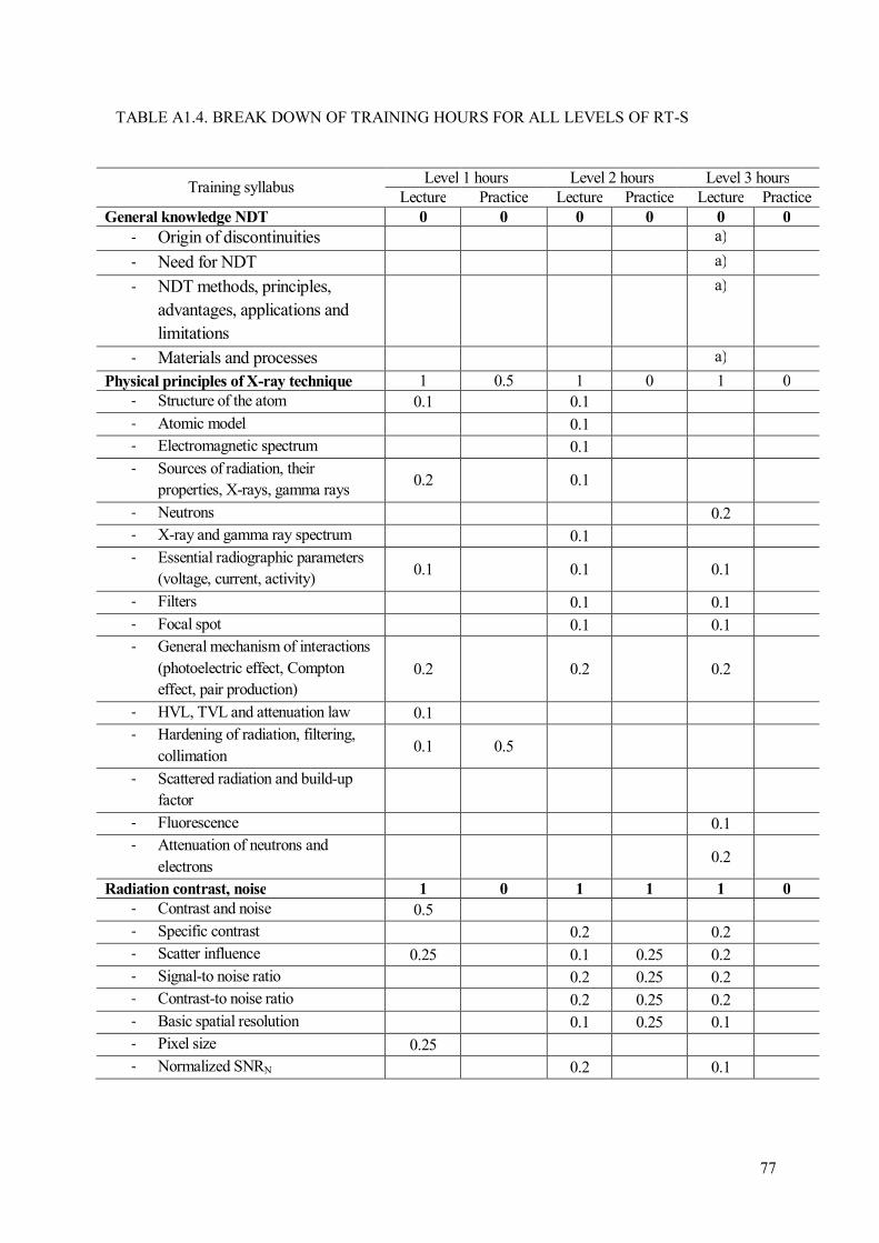
77
Training syllabus Level 1 hours Level 2 hours Level 3 hours
Lecture Practice Lecture Practice Lecture Practice General knowledge NDT 0 0 0 0 0 0
- Origin of discontinuities a)
- Need for NDT a)
- NDT methods, principles,
advantages, applications and
limitations
a)
- Materials and processes a)
Physical principles of X-ray technique 1 0.5 1 0 1 0 - Structure of the atom 0.1 0.1
- Atomic model 0.1 - Electromagnetic spectrum 0.1
- Sources of radiation, their properties, X-rays, gamma rays
0.2 0.1
- Neutrons 0.2 - X-ray and gamma ray spectrum 0.1 - Essential radiographic parameters
(voltage, current, activity) 0.1 0.1 0.1
- Filters 0.1 0.1
- Focal spot 0.1 0.1 - General mechanism of interactions
(photoelectric effect, Compton effect, pair production)
0.2 0.2 0.2
- HVL, TVL and attenuation law 0.1 - Hardening of radiation, filtering,
collimation 0.1 0.5
- Scattered radiation and build-up factor
- Fluorescence 0.1 - Attenuation of neutrons and
electrons 0.2
Radiation contrast, noise 1 0 1 1 1 0
- Contrast and noise 0.5 - Specific contrast 0.2 0.2 - Scatter influence 0.25 0.1 0.25 0.2 - Signal-to noise ratio 0.2 0.25 0.2 - Contrast-to noise ratio 0.2 0.25 0.2 - Basic spatial resolution 0.1 0.25 0.1 - Pixel size 0.25 - Normalized SNRN 0.2 0.1
TABLE A1.4. BREAK DOWN OF TRAINING HOURS FOR ALL LEVELS OF RT-S

Training syllabus Level 1 hours Level 2 hours Level 3 hours Lecture Practice Lecture Practice Lecture Practice
b) Geometrical projection conditions 1.5 2 2 2 2 1
- Geometrical and inherent
unsharpness 0.25 0.5 0.25 0.5 0.4 0.5
- Geometrical magnification 0.25 0.5 0.25 - Effect of magnification 0.5 0.5 0.5 1 0.4 - Optimum magnification 0.25 0.4 0.5 - Difference between radiography
and radioscopy 0.5 0.4
- Law oft he squared distances 0.5 0.5 0.25 0.5 0.4 Optimisation of image quality 1 0 1 1 1 0
- Compensation principles
- Contrast vs. SNR
- Basic spatial resolution
- Local unsharpness vs. SNR
- Scatter protection
- Maximum/optimum X-ray voltage
0.5
0.5
0.3 0.3
0.2 0.2
0.5 0.5
0.2 0.2 0.2 0.2 0.2
Image quality indicators, standards - Wire type
- Step hole type
- Plate hole type
- Duplex wire type
- Measurement of basic spatial resolution
- Converging line pairs
- Line pair gauges (MTF)
- Standards (see clause Table 2)
1
0.25 0.25 0.25 0.25
1
0.25 0.25 0.25 0.25
0
0
0
0
Equipment and work – Radiation sources
- X-Ray sources
o Standard sources
o Special source o Generation of high voltage
o Cooling o Handling
o Parameters : kV, mA, spot
size o Measurement of
parameters - Gamma sources and containers
o Handling and projector
o Special design
o Parameters: isotope, activity, source size
1
0.25
0.25
0.25
0.25
2
0.5
0.5 0.5
0.5
1
0.1 0.3 0.2
0.1
0.1 0.1 0.1
1
0.2 0.2
0.25
0.25 0.1
1.5
0.4 0.1
0.1
0.5
0.1 0.1 0.2
0
TABLE A1.4. BREAK DOWN OF TRAINING HOURS FOR ALL LEVELS OF RT-S (cont.)
78

79
Training syllabus Level 1 hours Level 2 hours Level 3 hours
Lecture Practice Lecture Practice Lecture Practice Equipment and work – detectors : CR,
imaging plates
- Phosphor imaging plates,
introduction and design
- Imaging plate and CR scanner
- CR system and classification
- Quality assurance (phantom)
- Exposure conditions and diagrams
- Handling
- System selection
1
0.5
0.25
0.25
0
1
0.2 0.2 0.2 0.3 0.1
0
1
0.1 0.1 0.2 0.2 0.2 0.2
0
Equipment and work – detectors : DDAs
- Digital Detector Arrays (DDA)- Introduction and design
o Indirect converting
o Direct converting o CCD, amorph, Si, CMOS
- Detector calibration
- Quality assurance
- Exposure conditions
- Handling
- System selection
1.5
0.5
0.5 0.5
1
0.25
0.25
0.25 0.25
1
0.5
0.25 0.25
1
0.25 0.25 0.25 0.25
1
0.25
0.25 0.1
0.1 0.3
1
0.25 0.25 0.5
Equipment and work – detectors : LDAs
- Line Detector Arrays (LDAs)- Introduction and design
- Application areas
- Comparison to DDAs
- Quality assurance
- Exposure conditions
- Handling
- System selection
0.5 0.25
0.25
0
0.5 0.25
0.25
0
0.5 0.1
0.1 0.1 0.1
0.1
0
Equipment and work – detectors :
intensifiers, fluoroscope
- Introduction and design
- Application areas
- Quality assurance
- Exposure conditions
- Handling
- System selection
- Comparison to DDAs
1
0.4 0.2
0.2
0.2
1
0.25
0.5 0.25
1
0.25 0.25
0.25
0.25
1
0.25 0.25 0.25 0.25
0.5
0.1 0.1 0.1
0.1 0.1
0.5
0.5
TABLE A1.4. BREAK DOWN OF TRAINING HOURS FOR ALL LEVELS OF RT-S (cont.)

Training syllabus Level 1 hours Level 2 hours Level 3 hours
Lecture Practice Lecture Practice Lecture Practice Equipment and work – detectors : film
digitization
- Scanner design
o Camera based o Line scanners
o Laser scanners
- Quality assurance (EPRI test film)
- Handling, archiving
- System selection
- Classification
0
0
0
0
0
0
Data acquisition, detector calibration
- A/D interface
- Computer structure o Processor, memory, bus,
disk o Load and save of digital
images
o Image formats
- Image integration
o On chip integration o In memory integration
o Optimum gain and latitude settings
o Accumulation vs.
integration
0
0
1
0.25 0.25
0.5
1
1
1
0.3 0.2
0.5
0
Digital image processing 2 2 5 4 3 3
- Image structure, quantisation
- (bits and bytes) 0.5 0.5 0.25
- Basic operation (picture element-
pixel, gray value) 0.75 1 0.5 0.25
- Point operations (contrast,
brightness, gamma correction, histogram, LUT)
0.75 1 0.5 0.5 0.5 0.5
- Matrix operations, filter
(smoothing, improvement of SNR, high pass, gradient, edge
enhancement, line extraction)
2 1 1.5 1.5
- Measurement tools (calibration,
line profile, measurement of flaw
length, areas, depth) 0.5 1.5 1
- Correction of raw data
(linearisation, LUT correction, bad pixel interpolation)
1 1 0.5
TABLE A1.4. BREAK DOWN OF TRAINING HOURS FOR ALL LEVELS OF RT-S (cont.)
80

81
Training syllabus Level 1 hours Level 2 hours Level 3 hours
Lecture Practice Lecture Practice Lecture Practice Standards
- Guides
- Qualification of sources
- General qualification of detectors
- User qualification of detectors
- See Table 2
1 0.5
0.5
1
0.5
0.5
3
0.5 0.5 2
3
0.5
2.5
2 0.5 0.5 0.5 0.5
0
Defectology, digital catalogues
- General welding (ISO 6520) and casting defects (ASTM casting
catalogues)
- Evaluation of welding: IIW
catalogue ISO 5817
- Evaluation of casting: ASTM
catalogues
- Corrosion
0.5
0.25
0.25
0.5
0.25
0.25
1
0.5
0.5
1
0.5
0.5
1.5
0.5
0.5
0.5
0
Automated image interpretation
- Principles
- Binarisation
- Measurement of dimensions
0
0
1
0.5 0.25 0.25
1
0.5 0.5
0.5
0.5
0.5
0.25 0.25
b) Special techniques, computed
tomography
- Stereo radiography
- Laminography
o Computed tomography o Inspection geometry
o 2D vs. 3D o Reconstruction principles
o Filtered backprojection
o Applications o Requirements and limit of
method
- Special CT techniques
0
0
1
0.25
0.5
0.25
1
1
0.5
0.25 0.25
0.5
0.5
Applications, standard practices and
evaluation 2 3 2.5 2 1.5 2
- Welds (standard practices with
different exposure geometries,
interpretation of digital images, digital processing of images,
evaluation of flaws, measurement of flaw dimensions, written
instruction/procedure)
1 1.5 1 1 0.5 1
TABLE A1.4. BREAK DOWN OF TRAINING HOURS FOR ALL LEVELS OF RT-S (cont.)

a) In addition to the above 32 hours a general knowledge common core course for level 3 (applicable to all NDT methods) is recommended, which shall be successfully completed only once.
b) More hours are recommended for RT-CT related training.
c) National laws and regulations are to be considered for training on radiation safety and handling of radiation sources. Radiation safety may be trained in separated courses, or training hours should be considered to be additional to those of the syllabus requirements (see TECDOC-628/Rev.2).
Training syllabus Level 1 hours Level 2 hours Level 3 hours Lecture Practice Lecture Practice Lecture Practice
- Castings (standard practices with different exposure geometries,
interpretation of digital images,
digital processing of images, evaluation of flaws, use of
catalogues, measurement of flaw dimensions, written
instruction/procedure)
1 1.5 1 1 0.5 1
- Corrosion wall thickness measurement (tangential RT,
double wall RT, calibration of digital images, measurement of
thickness, written
instruction/procedure)
- Others… 0.5 0.5 Written procedure/ instructions 0 0 1 1 1 1
- Welds 0.5 0.5 0.5 0.5 - Castings 0.5 0.5 0.5 0.5 - Corrosion wall thickness
measurement
c)Radiation protection
Extra training course depending on national regulations recommended
1
1
1
1
1
1
Total 17 15 26 22 21.5 10.5
32 48 32
TABLE A1.4. BREAK DOWN OF TRAINING HOURS FOR ALL LEVELS OF RT-S (cont.)
82
@ No. 23
ORDERING LOCALLYIn the following countries, IAEA priced publications may be purchased from the sources listed below or from major local booksellers.
Orders for unpriced publications should be made directly to the IAEA. The contact details are given at the end of this list.
AUSTRALIADA Information Services648 Whitehorse Road, Mitcham, VIC 3132, AUSTRALIA Telephone: +61 3 9210 7777 Fax: +61 3 9210 7788 Email: [email protected] Web site: http://www.dadirect.com.au
BELGIUMJean de LannoyAvenue du Roi 202, 1190 Brussels, BELGIUM Telephone: +32 2 5384 308 Fax: +32 2 5380 841 Email: [email protected] Web site: http://www.jean-de-lannoy.be
CANADARenouf Publishing Co. Ltd.5369 Canotek Road, Ottawa, ON K1J 9J3, CANADA Telephone: +1 613 745 2665 Fax: +1 643 745 7660 Email: [email protected] Web site: http://www.renoufbooks.com
Bernan Associates4501 Forbes Blvd., Suite 200, Lanham, MD 20706-4391, USA Telephone: +1 800 865 3457 Fax: +1 800 865 3450 Email: [email protected] Web site: http://www.bernan.com
CZECH REPUBLICSuweco CZ, spol. S.r.o.Klecakova 347, 180 21 Prague 9, CZECH REPUBLIC Telephone: +420 242 459 202 Fax: +420 242 459 203 Email: [email protected] Web site: http://www.suweco.cz
FINLANDAkateeminen KirjakauppaPO Box 128 (Keskuskatu 1), 00101 Helsinki, FINLAND Telephone: +358 9 121 41 Fax: +358 9 121 4450 Email: [email protected] Web site: http://www.akateeminen.com
FRANCEForm-Edit5 rue Janssen, PO Box 25, 75921 Paris CEDEX, FRANCE Telephone: +33 1 42 01 49 49 Fax: +33 1 42 01 90 90 Email: [email protected] Web site: http://www.formedit.fr
Lavoisier SAS14 rue de Provigny, 94236 Cachan CEDEX, FRANCE Telephone: +33 1 47 40 67 00 Fax: +33 1 47 40 67 02 Email: [email protected] Web site: http://www.lavoisier.fr
L’Appel du livre99 rue de Charonne, 75011 Paris, FRANCE Telephone: +33 1 43 07 50 80 Fax: +33 1 43 07 50 80 Email: [email protected] Web site: http://www.appeldulivre.fr
GERMANYGoethe Buchhandlung Teubig GmbHSchweitzer Fachinformationen Willstätterstrasse 15, 40549 Düsseldorf, GERMANY Telephone: +49 (0) 211 49 8740 Fax: +49 (0) 211 49 87428 Email: [email protected] Web site: http://www.goethebuch.de
HUNGARYLibrotade Ltd., Book ImportPF 126, 1656 Budapest, HUNGARY Telephone: +36 1 257 7777 Fax: +36 1 257 7472 Email: [email protected] Web site: http://www.librotade.hu

INDIAAllied Publishers1st Floor, Dubash House, 15, J.N. Heredi Marg, Ballard Estate, Mumbai 400001, INDIA Telephone: +91 22 2261 7926/27 Fax: +91 22 2261 7928 Email: [email protected] Web site: http://www.alliedpublishers.com
Bookwell3/79 Nirankari, Delhi 110009, INDIA Telephone: +91 11 2760 1283/4536 Email: [email protected] Web site: http://www.bookwellindia.com
ITALYLibreria Scientifica “AEIOU”Via Vincenzo Maria Coronelli 6, 20146 Milan, ITALY Telephone: +39 02 48 95 45 52 Fax: +39 02 48 95 45 48 Email: [email protected] Web site: http://www.libreriaaeiou.eu
JAPANMaruzen Co., Ltd.1-9-18 Kaigan, Minato-ku, Tokyo 105-0022, JAPAN Telephone: +81 3 6367 6047 Fax: +81 3 6367 6160 Email: [email protected] Web site: http://maruzen.co.jp
NETHERLANDSMartinus Nijhoff InternationalKoraalrood 50, Postbus 1853, 2700 CZ Zoetermeer, NETHERLANDS Telephone: +31 793 684 400 Fax: +31 793 615 698 Email: [email protected] Web site: http://www.nijhoff.nl
Swets Information Services Ltd.PO Box 26, 2300 AA LeidenDellaertweg 9b, 2316 WZ Leiden, NETHERLANDS Telephone: +31 88 4679 387 Fax: +31 88 4679 388 Email: [email protected] Web site: http://www.swets.com
SLOVENIACankarjeva Zalozba ddKopitarjeva 2, 1515 Ljubljana, SLOVENIA Telephone: +386 1 432 31 44 Fax: +386 1 230 14 35 Email: [email protected] Web site: http://www.mladinska.com/cankarjeva_zalozba
SPAINDiaz de Santos, S.A.Librerias Bookshop Departamento de pedidos Calle Albasanz 2, esquina Hermanos Garcia Noblejas 21, 28037 Madrid, SPAIN Telephone: +34 917 43 48 90 Fax: +34 917 43 4023 Email: [email protected] Web site: http://www.diazdesantos.es
UNITED KINGDOMThe Stationery Office Ltd. (TSO)PO Box 29, Norwich, Norfolk, NR3 1PD, UNITED KINGDOM Telephone: +44 870 600 5552 Email (orders): [email protected] (enquiries): [email protected] Web site: http://www.tso.co.uk
UNITED STATES OF AMERICABernan Associates4501 Forbes Blvd., Suite 200, Lanham, MD 20706-4391, USA Telephone: +1 800 865 3457 Fax: +1 800 865 3450 Email: [email protected] Web site: http://www.bernan.com
Renouf Publishing Co. Ltd.812 Proctor Avenue, Ogdensburg, NY 13669, USA Telephone: +1 888 551 7470 Fax: +1 888 551 7471 Email: [email protected] Web site: http://www.renoufbooks.com
United Nations300 East 42nd Street, IN-919J, New York, NY 1001, USA Telephone: +1 212 963 8302 Fax: 1 212 963 3489 Email: [email protected] Web site: http://www.unp.un.org
Orders for both priced and unpriced publications may be addressed directly to:IAEA Publishing Section, Marketing and Sales Unit, International Atomic Energy Agency Vienna International Centre, PO Box 100, 1400 Vienna, Austria Telephone: +43 1 2600 22529 or 22488 • Fax: +43 1 2600 29302 Email: [email protected] • Web site: http://www.iaea.org/books 15
-25691