Embed Size (px)
Citation preview
Province Government Bagmati Province
Ministry of Physical Infrastructure Development Transport Infrastructure Directorate
Hetauda, Makawanpur, Nepal
GuidelinesFor
Survey, Design and Preparation of Detailed Project Report (DPR) of Roads
2021Hetauda, Nepal

Guidelines for Survey Works Including Preparation of Detailed Project Report (DPR) of Roads
PREAMBLES Bagmati Province is one of the seven provinces of Nepal, formed on 20 September 2015
following Schedule of 4 of the constitution of Nepal. It is situated at the center of the country that
includes the capital of Nepal, Kathmandu. The province is located in between Tibet (China) in the
north and province 2 in the south. The province covers an area of 20,300 sq. km and 13 districts
of the 77 districts of Nepal. At the local level, there are 3 metropolitan cities, 1 sub-metropolitan
city, 41 urban municipalities, and 74 rural municipalities in the province. The population of the
province is 5,529,452 as per the census of 2011.
Bagmati Province Government, Ministry of Physical Infrastructure Development, Transport
Infrastructure Directorate is responsible for the planning, implementation, and maintenance
activities related to provincial roads and bridges within the province. For qualitative and
sustainable development of roads and uniform and consistency in the road design process and
preparation of detailed project report of the road project, this Guideline for Survey, Design and
Preparation of Detailed Project Report (DPR) of Road, 2021 is prepared. This guideline aims
to provide technical assistance for the preparation of DPR of all roads within Bagmati province.
Very special gratitude goes to Chief Minister Mr. Dormani Paudel, Chief Minister, Minister of
Ministry of Physical Infrastructure Development of Bagmati Province, Mr. Rameshwor Phuyal,
and Mr. Sanjeeb Baral, Secretary, Ministry of Physical Infrastructure Development of Bagmati
Province who gave suggestions and feedback during the preparation of this guideline. I would
also like to acknowledge many appreciations the crucial role of Mr. Aashish Khadka, a Road
Expert who worked actively to prepare this guideline. I would also like to thank SDE Mr. Puskar
Prasad Pokhrel, SDE Mr. Navin Kumar Singh, Er. Hari Prasad Ojha, Road Expert Er. Ram
Babu Paudyal, Account Officer Rajesh Thapa, and other colleagues for their comments that
helped in improving this guideline.
………………………..
Dr. Sahadev Bahadur Bhandari
Acting Director
- i -
Guidelines for Survey, Design and Preparation of Detailed Project Report (DPR) of Roads
Transport Infrastructure Directorate, Hetauda

- ii -
Guidelines for Survey, Design and Preparation of Detailed Project Report (DPR) of Roads
Transport Infrastructure Directorate, Hetauda
Guidelines for Survey Works Including Preparation of Detailed Project Report (DPR) of Roads
TABLE OF CONTENTS
PREAMBLES ......................................................................................................................................i
TABLE OF CONTENTS .................................................................................................................... ii
LIST OF FIGURES ............................................................................................................................ v
LIST OF TABLES .............................................................................................................................. v
LIST OF APPENDIX ......................................................................................................................... vi
ABBREVIATIONS AND ACRONYMS ............................................................................................ vii
1 INTRODUCTION ......................................................................................................................... 1
Transport Infrastructure Directorate (TID) ............................................................................. 1 1.1
Scopes and Works of TID ...................................................................................................... 1 1.2
Classification of the Province Road ....................................................................................... 1 1.3
Objective of Guidelines .......................................................................................................... 2 1.4
Scope ..................................................................................................................................... 3 1.5
Content ................................................................................................................................... 3 1.6
2 STAGES IN PROJECT PREPARATION .................................................................................... 4
2.1 Initial Identification ................................................................................................................. 4
2.2 Screening ............................................................................................................................... 4
2.3 Ranking and Prioritization ...................................................................................................... 5
2.4 Feasibility Study ..................................................................................................................... 6
2.5 Detailed Engineering Study ................................................................................................... 6
3 SURVEYS AND INVESTIGATIONS ........................................................................................... 7
3.1 Guiding Principles of Route Selection and Alignment Improvement .................................... 7
3.2 Reconnaissance Survey ........................................................................................................ 8
3.2.1 Survey Method .............................................................................................................. 8
3.2.2 Reconnaissance Report ............................................................................................... 9
3.3 Road Inventory Survey .......................................................................................................... 9
3.4 Pavement Condition Survey .................................................................................................. 9
3.5 Inventory and Condition Survey of Existing Bridges, Culverts and Other Structures ........ 10
3.6 Socio-Economic Profile Survey ........................................................................................... 10
3.7 Topographical Survey for Road Works ............................................................................... 11
3.7.1 Objectives ................................................................................................................... 11
3.7.2 Control Station ............................................................................................................ 12
3.7.3 Detailed Survey ........................................................................................................... 13
3.7.4 Digital Terrain Model (DTM) Preparation ................................................................... 14
3.7.5 Topographical Mapping .............................................................................................. 14
3.7.6 Topographical Survey Reports ................................................................................... 15
3.8 Topographical Survey for Bridge Works.............................................................................. 15
3.9 Differential Global Positioning System (DGPS) .................................................................. 16
3.10 Drone Survey ....................................................................................................................... 17
3.10.1 Benefits of Drone Survey ............................................................................................ 17
- iii -
Guidelines for Survey, Design and Preparation of Detailed Project Report (DPR) of Roads
Transport Infrastructure Directorate, Hetauda
Guidelines for Survey Works Including Preparation of Detailed Project Report (DPR) of Roads
3.10.2 Methodology................................................................................................................ 17
3.11 Hydrographical Survey ........................................................................................................ 18
3.12 Geological and Geotechnical Survey .................................................................................. 19
3.12.1 Engineering Geological Survey .................................................................................. 19
3.12.2 Geo-technical Survey ................................................................................................. 20
3.13 Cadastral Survey ................................................................................................................. 22
3.14 Assessment of Bioengineering Works ................................................................................. 22
3.15 Traffic Surveys ..................................................................................................................... 23
3.15.1 Classified Traffic Volume Counts ............................................................................... 23
3.15.2 Axle Load Survey ........................................................................................................ 24
3.15.3 Accident Records ........................................................................................................ 24
3.15.4 Traffic Projections ....................................................................................................... 24
3.16 Material Availability Survey .................................................................................................. 24
4 DESIGN ..................................................................................................................................... 26
4.1 Design Standards ................................................................................................................ 26
4.2 Engineering Design.............................................................................................................. 27
4.2.1 Interactive Design Environment .................................................................................. 27
4.2.2 Geometric and Cross-Section Design ........................................................................ 27
4.2.3 Design of Extra Widening, and Super Elevation ........................................................ 27
4.2.4 Design of Retaining Structures ................................................................................... 27
4.2.5 Design of Pavements .................................................................................................. 28
4.2.6 Design of Drainage and Cross Drainage System ...................................................... 28
4.2.7 Design of Traffic Safety Features and Road Markings .............................................. 32
4.2.8 Design of Bio-Engineering Measures ......................................................................... 32
4.2.9 Design of Ancillary Works ........................................................................................... 45
4.3 Preparation of Drawings ...................................................................................................... 46
4.3.1 General ....................................................................................................................... 46
4.3.2 Drawing ....................................................................................................................... 46
4.4 Preparation of Cost and Quantity Estimates ....................................................................... 47
4.5 Preparation of Bill of Quantities (BOQ) ............................................................................... 47
4.6 Preparation of Bid Documents ............................................................................................. 48
5 ECONOMIC ANALYSIS ............................................................................................................ 49
5.1 Introduction .......................................................................................................................... 49
5.2 General Approach ................................................................................................................ 49
5.3 Economic Evaluation ........................................................................................................... 49
5.4 Investment Decision and Criteria......................................................................................... 51
6 ENVIRONMENTAL ASSESSMENT ......................................................................................... 52
7 SOCIAL ASSESSMENT ........................................................................................................... 53

- iv -
Guidelines for Survey, Design and Preparation of Detailed Project Report (DPR) of Roads
Transport Infrastructure Directorate, Hetauda
Guidelines for Survey Works Including Preparation of Detailed Project Report (DPR) of Roads
8 PREPRATION AND PRESENTATION OF PROJECT DOCUMENTS DETAILED PROJECT
REPORT ................................................................................................................................... 54
8.1 General ................................................................................................................................ 54
8.2 Main Report .......................................................................................................................... 54
8.3 Drawings .............................................................................................................................. 54
8.4 Cost Estimates ..................................................................................................................... 54
BIBLIOGRAPHY ............................................................................................................................. 55
- v -
Guidelines for Survey, Design and Preparation of Detailed Project Report (DPR) of Roads
Transport Infrastructure Directorate, Hetauda
Guidelines for Survey Works Including Preparation of Detailed Project Report (DPR) of Roads
LIST OF FIGURES
Figure 1.1 : Organogram of TID ........................................................................................................ 1
Figure 2.1 : Stages in Project Preparation ........................................................................................ 4
Figure 3.1 : Sample of Topographic Map ........................................................................................ 15
Figure 3.2 : Flow Chart for Data Collection and Processing ........................................................... 18
Figure 3.3 : A complete set of TRL DCP instrument ....................................................................... 21
Figure 4.1 : Example of Cross-Section Editing with Structures and Drains ................................... 27
LIST OF TABLES
Table 4.1 : Recommended Design Parameters for Provincial Roads ............................................ 26
Table 4.2 : Recommended Design Parameters for Bridge ............................................................. 26
Guidelines for Survey Works Including Preparation of Detailed Project Report (DPR) of Roads
Transport Infrastructure Directorate, Hetauda vi
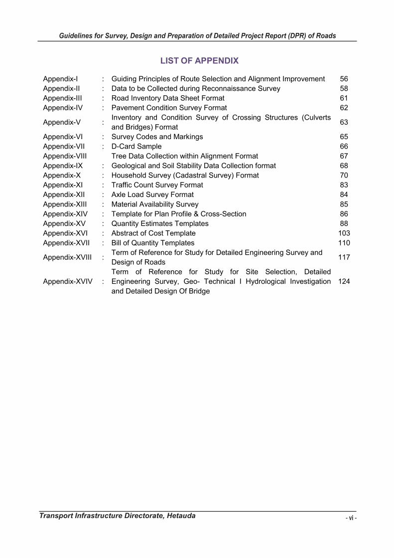
LIST OF APPENDIX
Appendix-I : Guiding Principles of Route Selection and Alignment Improvement 56
Appendix-II : Data to be Collected during Reconnaissance Survey 58
Appendix-III : Road Inventory Data Sheet Format 61
Appendix-IV : Pavement Condition Survey Format 62
Appendix-V : Inventory and Condition Survey of Crossing Structures (Culverts
and Bridges) Format 63
Appendix-VI : Survey Codes and Markings 65
Appendix-VII : D-Card Sample 66
Appendix-VIII Tree Data Collection within Alignment Format 67
Appendix-IX : Geological and Soil Stability Data Collection format 68
Appendix-X : Household Survey (Cadastral Survey) Format 70
Appendix-XI : Traffic Count Survey Format 83
Appendix-XII : Axle Load Survey Format 84
Appendix-XIII : Material Availability Survey 85
Appendix-XIV : Template for Plan Profile & Cross-Section 86
Appendix-XV : Quantity Estimates Templates 88
Appendix-XVI : Abstract of Cost Template 103
Appendix-XVII : Bill of Quantity Templates 110
Appendix-XVIII : Term of Reference for Study for Detailed Engineering Survey and
Design of Roads 117
Appendix-XVIV :
Term of Reference for Study for Site Selection, Detailed
Engineering Survey, Geo- Technical I Hydrological Investigation
and Detailed Design Of Bridge
124
- vi -
Guidelines for Survey, Design and Preparation of Detailed Project Report (DPR) of Roads
Transport Infrastructure Directorate, Hetauda
Guidelines for Survey Works Including Preparation of Detailed Project Report (DPR) of Roads
Transport Infrastructure Directorate, Hetauda vii
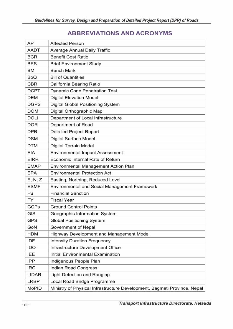
ABBREVIATIONS AND ACRONYMS
AP Affected Person
AADT Average Annual Daily Traffic
BCR Benefit Cost Ratio
BES Brief Environment Study
BM Bench Mark
BoQ Bill of Quantities
CBR California Bearing Ratio
DCPT Dynamic Cone Penetration Test
DEM Digital Elevation Model
DGPS Digital Global Positioning System
DOM Digital Orthographic Map
DOLI Department of Local Infrastructure
DOR Department of Road
DPR Detailed Project Report
DSM Digital Surface Model
DTM Digital Terrain Model
EIA Environmental Impact Assessment
EIRR Economic Internal Rate of Return
EMAP Environmental Management Action Plan
EPA Environmental Protection Act
E, N, Z Easting, Northing, Reduced Level
ESMF Environmental and Social Management Framework
FS Financial Sanction
FY Fiscal Year
GCPs Ground Control Points
GIS Geographic Information System
GPS Global Positioning System
GoN Government of Nepal
HDM Highway Development and Management Model
IDF Intensity Duration Frequency
IDO Infrastructure Development Office
IEE Initial Environmental Examination
IPP Indigenous People Plan
IRC Indian Road Congress
LIDAR Light Detection and Ranging
LRBP Local Road Bridge Programme
MoPID Ministry of Physical Infrastructure Development, Bagmati Province, Nepal
Guidelines for Survey Works Including Preparation of Detailed Project Report (DPR) of Roads
Transport Infrastructure Directorate, Hetauda viii
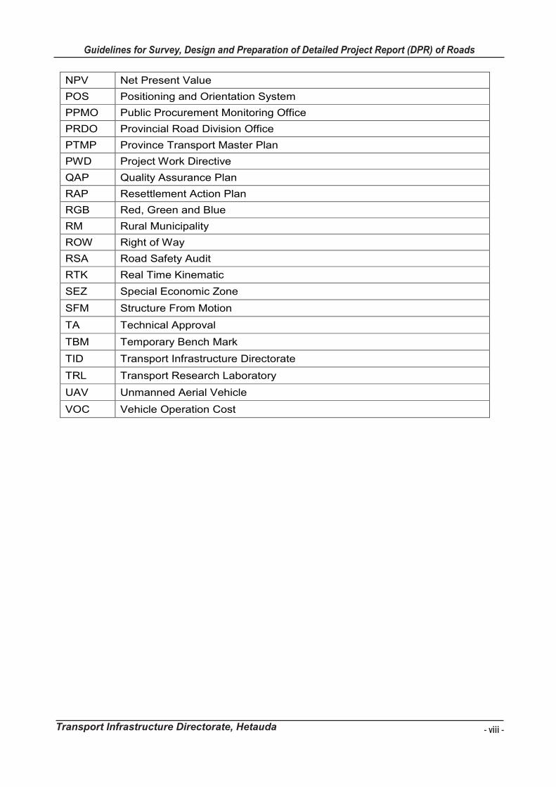
NPV Net Present Value
POS Positioning and Orientation System
PPMO Public Procurement Monitoring Office
PRDO Provincial Road Division Office
PTMP Province Transport Master Plan
PWD Project Work Directive
QAP Quality Assurance Plan
RAP Resettlement Action Plan
RGB Red, Green and Blue
RM Rural Municipality
ROW Right of Way
RSA Road Safety Audit
RTK Real Time Kinematic
SEZ Special Economic Zone
SFM Structure From Motion
TA Technical Approval
TBM Temporary Bench Mark
TID Transport Infrastructure Directorate
TRL Transport Research Laboratory
UAV Unmanned Aerial Vehicle
VOC Vehicle Operation Cost
- vii -
Guidelines for Survey, Design and Preparation of Detailed Project Report (DPR) of Roads
Transport Infrastructure Directorate, Hetauda
Guidelines for Survey Works Including Preparation of Detailed Project Report (DPR) of Roads
Transport Infrastructure Directorate, Hetauda viii
NPV Net Present Value
POS Positioning and Orientation System
PPMO Public Procurement Monitoring Office
PRDO Provincial Road Division Office
PTMP Province Transport Master Plan
PWD Project Work Directive
QAP Quality Assurance Plan
RAP Resettlement Action Plan
RGB Red, Green and Blue
RM Rural Municipality
ROW Right of Way
RSA Road Safety Audit
RTK Real Time Kinematic
SEZ Special Economic Zone
SFM Structure From Motion
TA Technical Approval
TBM Temporary Bench Mark
TID Transport Infrastructure Directorate
TRL Transport Research Laboratory
UAV Unmanned Aerial Vehicle
VOC Vehicle Operation Cost
- viii -
Guidelines for Survey, Design and Preparation of Detailed Project Report (DPR) of Roads
Transport Infrastructure Directorate, Hetauda

Guidelines for Survey Works Including Preparation of Detailed Project Report (DPR) of Roads
Transport Infrastructure Directorate, Hetauda ix
OFFICES UNDER TID
Offices Contact Address
Provincial Road Division Office, Nuwakot [email protected]
Provincial Road Division Office, Khurkot [email protected]
Infrastructure Development Office, Ramechhap [email protected]
Infrastructure Development Office, Sindhupalchok [email protected]
Infrastructure Development Office, Kavrepalanchok [email protected]
Infrastructure Development Office, Lalitpur [email protected]
Infrastructure Development Office, Chitwan [email protected]
Infrastructure Development Office, Nuwakot [email protected]
- ix -
Guidelines for Survey, Design and Preparation of Detailed Project Report (DPR) of Roads
Transport Infrastructure Directorate, Hetauda
Guidelines for Survey Works Including Preparation of Detailed Project Report (DPR) of Roads
Transport Infrastructure Directorate, Hetauda 1
1 INTRODUCTION
Transport Infrastructure Directorate (TID) 1.1
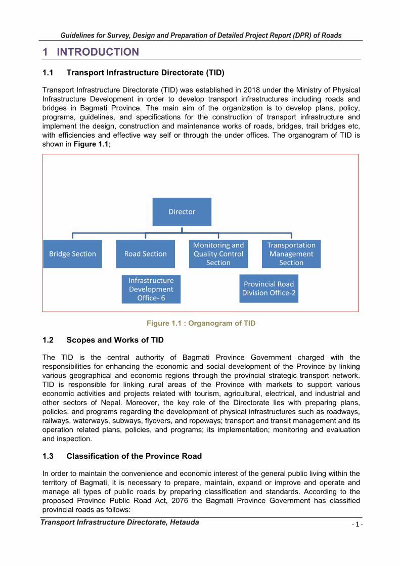
Transport Infrastructure Directorate (TID) was established in 2018 under the Ministry of Physical Infrastructure Development in order to develop transport infrastructures including roads and bridges in Bagmati Province. The main aim of the organization is to develop plans, policy, programs, guidelines, and specifications for the construction of transport infrastructure and implement the design, construction and maintenance works of roads, bridges, trail bridges etc, with efficiencies and effective way self or through the under offices. The organogram of TID is shown in Figure 1.1;
Figure 1.1 : Organogram of TID
Scopes and Works of TID 1.2
The TID is the central authority of Bagmati Province Government charged with the responsibilities for enhancing the economic and social development of the Province by linking various geographical and economic regions through the provincial strategic transport network. TID is responsible for linking rural areas of the Province with markets to support various economic activities and projects related with tourism, agricultural, electrical, and industrial and other sectors of Nepal. Moreover, the key role of the Directorate lies with preparing plans, policies, and programs regarding the development of physical infrastructures such as roadways, railways, waterways, subways, flyovers, and ropeways; transport and transit management and its operation related plans, policies, and programs; its implementation; monitoring and evaluation and inspection.
Classification of the Province Road 1.3
In order to maintain the convenience and economic interest of the general public living within the territory of Bagmati, it is necessary to prepare, maintain, expand or improve and operate and manage all types of public roads by preparing classification and standards. According to the proposed Province Public Road Act, 2076 the Bagmati Province Government has classified provincial roads as follows:
Director
Bridge Section Road Section Monitoring and Quality Control
Section
Transportation Management
Section
Infrastructure Development
Office- 6
Provincial Road Division Office-2
- 1 -
Guidelines for Survey, Design and Preparation of Detailed Project Report (DPR) of Roads
Transport Infrastructure Directorate, Hetauda
Guidelines for Survey Works Including Preparation of Detailed Project Report (DPR) of Roads
Transport Infrastructure Directorate, Hetauda 1
1 INTRODUCTION
Transport Infrastructure Directorate (TID) 1.1
Transport Infrastructure Directorate (TID) was established in 2018 under the Ministry of Physical Infrastructure Development in order to develop transport infrastructures including roads and bridges in Bagmati Province. The main aim of the organization is to develop plans, policy, programs, guidelines, and specifications for the construction of transport infrastructure and implement the design, construction and maintenance works of roads, bridges, trail bridges etc, with efficiencies and effective way self or through the under offices. The organogram of TID is shown in Figure 1.1;
Figure 1.1 : Organogram of TID
Scopes and Works of TID 1.2
The TID is the central authority of Bagmati Province Government charged with the responsibilities for enhancing the economic and social development of the Province by linking various geographical and economic regions through the provincial strategic transport network. TID is responsible for linking rural areas of the Province with markets to support various economic activities and projects related with tourism, agricultural, electrical, and industrial and other sectors of Nepal. Moreover, the key role of the Directorate lies with preparing plans, policies, and programs regarding the development of physical infrastructures such as roadways, railways, waterways, subways, flyovers, and ropeways; transport and transit management and its operation related plans, policies, and programs; its implementation; monitoring and evaluation and inspection.
Classification of the Province Road 1.3
In order to maintain the convenience and economic interest of the general public living within the territory of Bagmati, it is necessary to prepare, maintain, expand or improve and operate and manage all types of public roads by preparing classification and standards. According to the proposed Province Public Road Act, 2076 the Bagmati Province Government has classified provincial roads as follows:
Director
Bridge Section Road Section Monitoring and Quality Control
Section
Transportation Management
Section
Infrastructure Development
Office- 6
Provincial Road Division Office-2
- 2 -
Guidelines for Survey, Design and Preparation of Detailed Project Report (DPR) of Roads
Transport Infrastructure Directorate, Hetauda
Guidelines for Survey Works Including Preparation of Detailed Project Report (DPR) of Roads
Transport Infrastructure Directorate, Hetauda 2
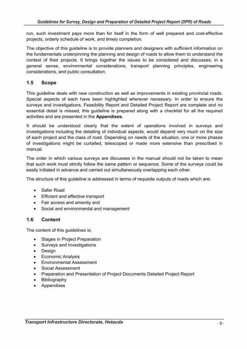
Province Expressway
Province Highway
Province Road
Province Urban Road
Province Other Transportation modes
Province Expressway
Province Expressway is the highway with controlled entrances and exits at designated places, two way traffic lane separated by median restricting lateral access to change the lane and no intersection at the grade. These are developed for high-speed traffic flow.
Province Highway
Province Highway is the road that connects to National Highway with Province Headquarters, District Headquarters with the National Highway or that connects Province Headquarter with District Headquarter or the Road connecting the District Headquarters with another District Headquarters within the Province or the Road or connecting two National Highways.
Province Road
Province Road means the road that connects the center of Local level with National Highways or Province Highway or District Headquarter or road connecting two or more Local centers, or National Highway and Province Highway connected with important market place, religious place, historical, touristic and other important places.
Province Urban Road
Urban Road" means urban ring road, road connecting important places within the city, flyover, elevated road, subway, sky (overhead) bridge or bypass (bypass).
Province Other Transportation
Other modes of transportation such as Rail Transport, Air transport, Water Transport, Cable etc. fall under this class.
Objective of Guidelines 1.4
Preparation of road projects involves a chain of activities, such as field surveys and
investigations, selection of alignment, carrying out various designs, preparation of drawings and
estimates, etc. To be compatible with technical requirements, consistent with the economy, every
project must be prepared after thorough investigations and collecting all relevant information, and
evaluating all possible alternatives.
The extent and quality of survey and investigations have a strong influence on the selection of
the most cost-effective design, estimation of quantities cost, and execution of the job itself. As
such, the accuracy and completeness of surveys deserve very special attention in project
preparation. The objective can be achieved by carrying out the project preparation work either
departmentally or with the help of consultants. In any case, it should be ensured that experts
having the required knowledge are deployed on the work. The use of modern instruments and
survey techniques ensures a high degree of accuracy and can speed up the work. A proper work
plan is required to be drawn before the start of field investigations.
Adequate funds should be earmarked for the work of survey, investigation, and project
preparation. Estimation of the realistic fund and time requirement needed for project preparation
will highly contribute in meeting goals and objectives of project. It will be found that in the long
Guidelines for Survey Works Including Preparation of Detailed Project Report (DPR) of Roads
Transport Infrastructure Directorate, Hetauda 3
run, such investment pays more than for itself in the form of well prepared and cost-effective
projects, orderly schedule of work, and timely completion.
The objective of this guideline is to provide planners and designers with sufficient information on
the fundamentals underpinning the planning and design of roads to allow them to understand the
context of their projects. It brings together the issues to be considered and discusses, in a
general sense, environmental considerations, transport planning principles, engineering
considerations, and public consultation.
Scope 1.5
This guideline deals with new construction as well as improvements in existing provincial roads.
Special aspects of each have been highlighted wherever necessary. In order to ensure the
surveys and investigations, Feasibility Report and Detailed Project Report are complete and no
essential detail is missed, this guideline is prepared along with a checklist for all the required
activities and are presented in the Appendixes.
It should be understood clearly that the extent of operations involved in surveys and
investigations including the detailing of individual aspects, would depend very much on the size
of each project and the class of road. Depending on needs of the situation, one or more phases
of investigations might be curtailed, telescoped or made more extensive than prescribed in
manual.
The order in which various surveys are discusses in the manual should not be taken to mean
that such work must strictly follow the same pattern or sequence. Some of the surveys could be
easily initiated in advance and carried out simultaneously overlapping each other.
The structure of this guideline is addressed in terms of requisite outputs of roads which are:
Safer Road
Efficient and effective transport
Fair access and amenity and
Social and environmental and management
Content 1.6
The content of this guidelines is;
Stages in Project Preparation
Surveys and Investigations
Design
Economic Analysis
Environmental Assessment
Social Assessment
Preparation and Presentation of Project Documents Detailed Project Report
Bibliography
Appendixes
- 3 -
Guidelines for Survey, Design and Preparation of Detailed Project Report (DPR) of Roads
Transport Infrastructure Directorate, Hetauda
Guidelines for Survey Works Including Preparation of Detailed Project Report (DPR) of Roads
Transport Infrastructure Directorate, Hetauda 3
run, such investment pays more than for itself in the form of well prepared and cost-effective
projects, orderly schedule of work, and timely completion.
The objective of this guideline is to provide planners and designers with sufficient information on
the fundamentals underpinning the planning and design of roads to allow them to understand the
context of their projects. It brings together the issues to be considered and discusses, in a
general sense, environmental considerations, transport planning principles, engineering
considerations, and public consultation.
Scope 1.5
This guideline deals with new construction as well as improvements in existing provincial roads.
Special aspects of each have been highlighted wherever necessary. In order to ensure the
surveys and investigations, Feasibility Report and Detailed Project Report are complete and no
essential detail is missed, this guideline is prepared along with a checklist for all the required
activities and are presented in the Appendixes.
It should be understood clearly that the extent of operations involved in surveys and
investigations including the detailing of individual aspects, would depend very much on the size
of each project and the class of road. Depending on needs of the situation, one or more phases
of investigations might be curtailed, telescoped or made more extensive than prescribed in
manual.
The order in which various surveys are discusses in the manual should not be taken to mean
that such work must strictly follow the same pattern or sequence. Some of the surveys could be
easily initiated in advance and carried out simultaneously overlapping each other.
The structure of this guideline is addressed in terms of requisite outputs of roads which are:
Safer Road
Efficient and effective transport
Fair access and amenity and
Social and environmental and management
Content 1.6
The content of this guidelines is;
Stages in Project Preparation
Surveys and Investigations
Design
Economic Analysis
Environmental Assessment
Social Assessment
Preparation and Presentation of Project Documents Detailed Project Report
Bibliography
Appendixes
- 4 -
Guidelines for Survey, Design and Preparation of Detailed Project Report (DPR) of Roads
Transport Infrastructure Directorate, Hetauda
Guidelines for Survey Works Including Preparation of Detailed Project Report (DPR) of Roads
Transport Infrastructure Directorate, Hetauda 4
2 STAGES IN PROJECT PREPARATION
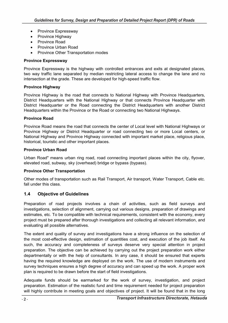
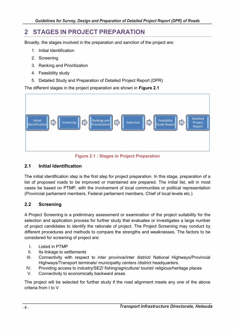
Broadly, the stages involved in the preparation and sanction of the project are:
1. Initial Identification
2. Screening
3. Ranking and Prioritization
4. Feasibility study
5. Detailed Study and Preparation of Detailed Project Report (DPR)
The different stages in the project preparation are shown in Figure 2.1
Figure 2.1 : Stages in Project Preparation
Initial Identification 2.1
The initial identification step is the first step for project preparation. In this stage, preparation of a
list of proposed roads to be improved or maintained are prepared. The initial list, will in most
cases be based on PTMP, with the involvement of local communities or political representation
(Provincial parliament members, Federal parliament members, Chief of local levels etc.)
Screening 2.2
A Project Screening is a preliminary assessment or examination of the project suitability for the
selection and application process for further study that evaluates or investigates a large number
of project candidates to identify the rationale of project. The Project Screening may conduct by
different procedures and methods to compare the strengths and weaknesses. The factors to be
considered for screening of project are:
I. Listed in PTMP II. Its linkage to settlements
III. Connectivity with respect to inter province/inter district/ National Highways/Provincial Highways/Transport terminals/ municipality centers /district headquarters.
IV. Providing access to industry/SEZ/ fishing/agriculture/ tourist/ religious/heritage places V. Connectivity to economically backward areas.
The project will be selected for further study if the road alignment meets any one of the above
criteria from I to V
Initial Identification
Screening Ranking and Prioritization
Selection Feasibility
Study Report
Detailed Project Report
Guidelines for Survey Works Including Preparation of Detailed Project Report (DPR) of Roads
Transport Infrastructure Directorate, Hetauda 5
Ranking and Prioritization 2.3
After screening of project, the next step is ranking and prioritization of roads. A network consists
of several links. It is not possible to construct all roads at a time due to resource and time
constraint. Therefore, each link in a network should be prioritized. An overall ranking of the
selected roads, on the basis of the overall population per unit cost, will be necessary in order to
decide which road should receive priority and in what order.
Population per unit cost has been taken as an important parameter for ranking and
prioritization of linkage. To prioritize the linkage from this parameter, population of influence area
and cost of linkage are required.
Population per unit cost is calculated from total population divided by investment cost in lakh
(hundred thousand) rupees i.e. no of person per 100000 rupees. The road having the highest
beneficiary’s population per investment cost is given highest score.
The principle criteria for ranking and prioritization criteria for road project consist of the following
index:
a) Population of Influence Area (Number of Population Served/Benefited)
b) Rough Estimates of Project Cost
a) Population of Influence Area (Number of Population Served/Benefited)
The population served is defined as the total population of all Municipalities and Rural
Municipalities. Population data is collected for each local bodies (total population only). The total
population served by each road as the sum of the populations of the different RM linked by the
road concerned as an estimation of the population served by each road. The population within
the zone of influence (ZOI) area i.e. left and right of the road link within 2 hours walking time in
terai and 4 hours walking time in hills and 6 hours in mountains is taken as the beneficiaries of a
proposed road. Estimating population within ZoI needs careful division.
After locating the ZoI, the settlements within that ZoI should be identified. Collection of settlement
level population is very difficult, so if settlement wise population is not available, ward-wise
population can be collected from Municipality/Rural Municipality office or other local level centers
and summed up all ward-wise population to get the total number of population
b) Rough Estimates of Project Cost
The rough estimates of the roads, the cost of the different interventions based on inventory
survey and DPR of similar roads within the districts needs to be estimated. This is done based
on a reconnaissance survey by collecting information on the present status of the road,
deficiency/distress identification, development potential, environmental impact, traffic data
(present and future) and an approximate estimation of cost.
Based on the total estimated cost and the number of populations benefited, the population per
unit costs are calculated and the roads are ranked and prioritized for further study. Prioritization
of the road projects shall be given in order of scoring.
Based on the prioritization of the local road and availability of budget of each year, further study
program shall be formulated.
- 5 -
Guidelines for Survey, Design and Preparation of Detailed Project Report (DPR) of Roads
Transport Infrastructure Directorate, Hetauda
Guidelines for Survey Works Including Preparation of Detailed Project Report (DPR) of Roads
Transport Infrastructure Directorate, Hetauda 5
Ranking and Prioritization 2.3
After screening of project, the next step is ranking and prioritization of roads. A network consists
of several links. It is not possible to construct all roads at a time due to resource and time
constraint. Therefore, each link in a network should be prioritized. An overall ranking of the
selected roads, on the basis of the overall population per unit cost, will be necessary in order to
decide which road should receive priority and in what order.
Population per unit cost has been taken as an important parameter for ranking and
prioritization of linkage. To prioritize the linkage from this parameter, population of influence area
and cost of linkage are required.
Population per unit cost is calculated from total population divided by investment cost in lakh
(hundred thousand) rupees i.e. no of person per 100000 rupees. The road having the highest
beneficiary’s population per investment cost is given highest score.
The principle criteria for ranking and prioritization criteria for road project consist of the following
index:
a) Population of Influence Area (Number of Population Served/Benefited)
b) Rough Estimates of Project Cost
a) Population of Influence Area (Number of Population Served/Benefited)
The population served is defined as the total population of all Municipalities and Rural
Municipalities. Population data is collected for each local bodies (total population only). The total
population served by each road as the sum of the populations of the different RM linked by the
road concerned as an estimation of the population served by each road. The population within
the zone of influence (ZOI) area i.e. left and right of the road link within 2 hours walking time in
terai and 4 hours walking time in hills and 6 hours in mountains is taken as the beneficiaries of a
proposed road. Estimating population within ZoI needs careful division.
After locating the ZoI, the settlements within that ZoI should be identified. Collection of settlement
level population is very difficult, so if settlement wise population is not available, ward-wise
population can be collected from Municipality/Rural Municipality office or other local level centers
and summed up all ward-wise population to get the total number of population
b) Rough Estimates of Project Cost
The rough estimates of the roads, the cost of the different interventions based on inventory
survey and DPR of similar roads within the districts needs to be estimated. This is done based
on a reconnaissance survey by collecting information on the present status of the road,
deficiency/distress identification, development potential, environmental impact, traffic data
(present and future) and an approximate estimation of cost.
Based on the total estimated cost and the number of populations benefited, the population per
unit costs are calculated and the roads are ranked and prioritized for further study. Prioritization
of the road projects shall be given in order of scoring.
Based on the prioritization of the local road and availability of budget of each year, further study
program shall be formulated.
- 6 -
Guidelines for Survey, Design and Preparation of Detailed Project Report (DPR) of Roads
Transport Infrastructure Directorate, Hetauda
Guidelines for Survey Works Including Preparation of Detailed Project Report (DPR) of Roads
Transport Infrastructure Directorate, Hetauda 6
Feasibility Study 2.4
The Feasibility Study is intended to establish whether the proposal is acceptable in terms of
soundness of engineering design and expected benefits from the project for the investments
involved. The Feasibility Report enables the funding agency to accord approval to the project.
When the international funding is involved, the Feasibility Study forms a basis for an investment.
Detailed Engineering Study 2.5
The Detailed Engineering covers detailed alignment surveys, soil and materials surveys,
pavement design studies, drainage studies, environment management plan based on
environmental impact assessment studies, detailed drawings, estimates, and implementation
schedules and documents. Based on such work, Technical Approval and Financial Sanction (TA
and FS) are accorded to the project, enabling it to be executed.
The sequence of survey operations and project preparation may thus, have to be structured to
meet the specific needs of the project, its funding option, and the requirements of the authority
sponsoring it.
Guidelines for Survey Works Including Preparation of Detailed Project Report (DPR) of Roads
Transport Infrastructure Directorate, Hetauda 7
3 SURVEYS AND INVESTIGATIONS
Preparation of road projects involves a chain of activities, such as, field surveys and
investigations, selection of alignment, carrying out various designs, preparation of drawings and
estimates, etc. To be compatible with technical requirements, consistent with economy, it is
essential that every project should be prepared after thorough investigations and collecting all
relevant information and evaluating all possible alternatives. The extent and quality of
investigations have a strong influence on selection of the most cost-effective design, estimation
of quantities cost and execution of the job itself. As such, accuracy and completeness of surveys
deserves very special attention in project preparation. The objective can be achieved by carrying
out the project preparation work either departmentally or with the help of consultants. In any
case, it should be ensured that experts having the required knowledge are deployed on the work.
Use of modern instruments and survey techniques ensure high degree of accuracy and can
speed up the work. Quality Assurance Plan is required to be drawn before the start of field
investigations. Adequate funds should be earmarked for the work of survey, investigation and
project preparation. Estimation of realistic fund and time requirement needed for project
preparation will go a long way in making the project preparation a success. It will be found that in
the long run, such investment pays more than for itself in the form of well prepared and cost
effective projects, orderly schedule of work and timely completion. Systematic presentation of
project details is no less important.
Guiding Principles of Route Selection and Alignment Improvement 3.1
The fundamental principle of route selection and alignment improvement is to achieve the least
overall cost on transportation, having regard to the costs of initial construction of the highway
facility, its maintenance, and road user cost, while at the same time, satisfying the social and
environmental requirements.
Factors that should be kept in view in the process are listed in Appendix-I
Where the project involves improvements to an existing road, every effort should be directed towards the inherent deficiencies concerning
Plan and profile Sight distance/visibility in horizontal as well vertical plan Carriageway, shoulder, and roadway width Cross-drainage structures Roadside drainage provisions as well as area drainage consideration Safety features.
Any disregard of these aspects may well lead to unnecessary expenditure, since at a later date
the alignment may again have to be improved at considerable extra cost. It is, therefore
imperative that the final centre line of with respect to which, the improvements are designed and
are to be carried out, is fixed with care in the light of ultimate geometric requirements and
economy. The other important point is removal of structural deficiencies with an eye on future
needs with respect to pavement, culverts, road and drainage requirement etc.
Proper location and orientation of cross drainage structure is an important factor in the selection
of the road alignment. The importance increases with their length and cost.
Apart from engineering factors, the environmental and social impact of the proposal should be
fully kept in view in terms of such aspects as air pollution, damage to life systems, soil erosion,
- 7 -
Guidelines for Survey, Design and Preparation of Detailed Project Report (DPR) of Roads
Transport Infrastructure Directorate, Hetauda
Guidelines for Survey Works Including Preparation of Detailed Project Report (DPR) of Roads
Transport Infrastructure Directorate, Hetauda 7
3 SURVEYS AND INVESTIGATIONS
Preparation of road projects involves a chain of activities, such as, field surveys and
investigations, selection of alignment, carrying out various designs, preparation of drawings and
estimates, etc. To be compatible with technical requirements, consistent with economy, it is
essential that every project should be prepared after thorough investigations and collecting all
relevant information and evaluating all possible alternatives. The extent and quality of
investigations have a strong influence on selection of the most cost-effective design, estimation
of quantities cost and execution of the job itself. As such, accuracy and completeness of surveys
deserves very special attention in project preparation. The objective can be achieved by carrying
out the project preparation work either departmentally or with the help of consultants. In any
case, it should be ensured that experts having the required knowledge are deployed on the work.
Use of modern instruments and survey techniques ensure high degree of accuracy and can
speed up the work. Quality Assurance Plan is required to be drawn before the start of field
investigations. Adequate funds should be earmarked for the work of survey, investigation and
project preparation. Estimation of realistic fund and time requirement needed for project
preparation will go a long way in making the project preparation a success. It will be found that in
the long run, such investment pays more than for itself in the form of well prepared and cost
effective projects, orderly schedule of work and timely completion. Systematic presentation of
project details is no less important.
Guiding Principles of Route Selection and Alignment Improvement 3.1
The fundamental principle of route selection and alignment improvement is to achieve the least
overall cost on transportation, having regard to the costs of initial construction of the highway
facility, its maintenance, and road user cost, while at the same time, satisfying the social and
environmental requirements.
Factors that should be kept in view in the process are listed in Appendix-I
Where the project involves improvements to an existing road, every effort should be directed towards the inherent deficiencies concerning
Plan and profile Sight distance/visibility in horizontal as well vertical plan Carriageway, shoulder, and roadway width Cross-drainage structures Roadside drainage provisions as well as area drainage consideration Safety features.
Any disregard of these aspects may well lead to unnecessary expenditure, since at a later date
the alignment may again have to be improved at considerable extra cost. It is, therefore
imperative that the final centre line of with respect to which, the improvements are designed and
are to be carried out, is fixed with care in the light of ultimate geometric requirements and
economy. The other important point is removal of structural deficiencies with an eye on future
needs with respect to pavement, culverts, road and drainage requirement etc.
Proper location and orientation of cross drainage structure is an important factor in the selection
of the road alignment. The importance increases with their length and cost.
Apart from engineering factors, the environmental and social impact of the proposal should be
fully kept in view in terms of such aspects as air pollution, damage to life systems, soil erosion,
- 8 -
Guidelines for Survey, Design and Preparation of Detailed Project Report (DPR) of Roads
Transport Infrastructure Directorate, Hetauda
Guidelines for Survey Works Including Preparation of Detailed Project Report (DPR) of Roads
Transport Infrastructure Directorate, Hetauda 8
drainage pattern, landscaping, disruption of local communities, resettlement, land acquisition,
etc.
Reconnaissance Survey 3.2
The main objective of the reconnaissance survey is to examine the general character of the area
to determine the most feasible routes for further more detailed investigations. Data collected
should be adequate to examine the feasibility of all the different routes and furnish the
approximate quantity estimates for deciding on the most suitable alternative or alternatives. The
survey should also help in determining basic geometric standards to be adopted for the highway
facility.
3.2.1 Survey Method
The reconnaissance survey may be conducted in the following sequence:
Study of topographical survey sheets, agricultural, soil, geological, and meteorological
maps, and aerial photographs, if available.
Aerial reconnaissance (where necessary and feasible)
Ground reconnaissance
3.2.1.1 Study of Topographical Survey Sheets
Reconnaissance begins with a study of all the available maps. The types of useful map information which are currently available in the country are topographical map, land use map, hydrological map, and geological map.
After the study of the topographical features on the maps, several alignments feasible in a general way are selected keeping in view the following points:
The alignment should take into account all the control points and should be the shortest
and most economical compatible with the requirements of grade and curvature.
The shape of the alignments.
Avoidance, as far as possible, of marshy ground, steep terrain, unstable hill features, and
areas subject to severe climatic conditions, flooding, and inundation.
Land use pattern, Soil type, village, settlements, etc.
The need of connecting important villages and towns.
Bridging cross-drainage and drainage problems.
Need to preserve the environment and maintain ecological balance.
Geology, geomorphology and groundwater prospecting and
Environmental factors, e.g., vegetation, soil condition, land use, etc.
3.2.1.2 Aerial Reconnaissance
An aerial reconnaissance will provide a bird's eye view of the alignments under consideration
along with the surrounding area. It will help to identify factors that call for rejection or modification
of any of the alignment. The final decision about the alignments to be studied in detail on the
ground could be taken based on the aerial reconnaissance.
3.2.1.3 Ground Reconnaissance Survey
The various alternative routes located as a result of the map study are further examined in the
field by ground reconnaissance. As such, this part of the survey is an important link in the chain
Guidelines for Survey Works Including Preparation of Detailed Project Report (DPR) of Roads
Transport Infrastructure Directorate, Hetauda 9
of activities leading to the selection of the final route. General reconnaissance consists of a
general examination of the ground walking or riding along the probable route and collecting all
available information necessary for evaluating the same. In the case of hill sections, it may
sometimes be advantageous to start the reconnaissance from the obligatory point situated close
to the top. If an area is inaccessible for the purposes of ground reconnaissance, recourse may
be had to aerial reconnaissance to clear the doubts.
While carrying out ground reconnaissance, it is advisable to leave reference pegs to facilitate
further survey operations.
Instruments generally used during ground reconnaissance include GPS, compass, Abney
level/Altimeter, Pedometer, Aneroid barometer, Clinometer, Ghat tracer, etc. Walkie-talkie sets,
mobile phones are useful for communication, particularly in difficult terrain. Use of the
instruments mentioned above to obtain ground slopes, maximum gradients, the elevation of
critical summits or stream crossings, and location of obligatory points, serve as a check on the
maps being used.
Points and Formats on which data may be collected during ground reconnaissance are listed in
Appendix II.
3.2.2 Reconnaissance Report
Based on the information collected during the reconnaissance survey, a report should be
prepared. The report should include all relevant information collected during the survey, a plan to
the scale of 1:50,000 or larger as available showing the alternative alignments studied along with
their general profile and rough cost estimates. It should discuss the merits and demerits of the
different alternatives to help the selection of one or more alignments for detailed survey and
investigation.
Road Inventory Survey 3.3
Many projects involve improvement to an existing road (strengthening/widening) or construction
of new facilities (bypasses) which are an improvement in traffic conditions over the existing
facility. In these cases, the scope of the improvement measures and economic justification for
them depends upon the condition of the existing pavement. It therefore, becomes necessary to
prepare a road inventory and carryout condition survey. An inventory of the project road shall be
carried out through dimensional measurement and visual inspection supplemented with sample
measurements using tape etc. Features like chainage, terrain and land-use, name of
village/town, type, condition and width of carriageway and shoulders, important road junctions
and geometric deficiencies, utilities etc., shall be recorded along with photographs. The format of
road inventory is presented in Appendix III.
Pavement Condition Survey 3.4
The pavement condition survey is a visual inspection of the pavement. The survey provides measures to assess the magnitudes of various types of pavement distress. This inventory will include such information as length, width, and type of pavement surface; shoulder and curb and gutter information. Additional information such as sidewalks, drainage, resurfacing, utility information, signs, etc. may be included. The result of a pavement condition survey indicate the overall condition of the road and will give an estimate of the amount of funding needed to preserve pavement. The format for pavement condition survey is in Appendix IV.
- 9 -
Guidelines for Survey, Design and Preparation of Detailed Project Report (DPR) of Roads
Transport Infrastructure Directorate, Hetauda
Guidelines for Survey Works Including Preparation of Detailed Project Report (DPR) of Roads
Transport Infrastructure Directorate, Hetauda 9
of activities leading to the selection of the final route. General reconnaissance consists of a
general examination of the ground walking or riding along the probable route and collecting all
available information necessary for evaluating the same. In the case of hill sections, it may
sometimes be advantageous to start the reconnaissance from the obligatory point situated close
to the top. If an area is inaccessible for the purposes of ground reconnaissance, recourse may
be had to aerial reconnaissance to clear the doubts.
While carrying out ground reconnaissance, it is advisable to leave reference pegs to facilitate
further survey operations.
Instruments generally used during ground reconnaissance include GPS, compass, Abney
level/Altimeter, Pedometer, Aneroid barometer, Clinometer, Ghat tracer, etc. Walkie-talkie sets,
mobile phones are useful for communication, particularly in difficult terrain. Use of the
instruments mentioned above to obtain ground slopes, maximum gradients, the elevation of
critical summits or stream crossings, and location of obligatory points, serve as a check on the
maps being used.
Points and Formats on which data may be collected during ground reconnaissance are listed in
Appendix II.
3.2.2 Reconnaissance Report
Based on the information collected during the reconnaissance survey, a report should be
prepared. The report should include all relevant information collected during the survey, a plan to
the scale of 1:50,000 or larger as available showing the alternative alignments studied along with
their general profile and rough cost estimates. It should discuss the merits and demerits of the
different alternatives to help the selection of one or more alignments for detailed survey and
investigation.
Road Inventory Survey 3.3
Many projects involve improvement to an existing road (strengthening/widening) or construction
of new facilities (bypasses) which are an improvement in traffic conditions over the existing
facility. In these cases, the scope of the improvement measures and economic justification for
them depends upon the condition of the existing pavement. It therefore, becomes necessary to
prepare a road inventory and carryout condition survey. An inventory of the project road shall be
carried out through dimensional measurement and visual inspection supplemented with sample
measurements using tape etc. Features like chainage, terrain and land-use, name of
village/town, type, condition and width of carriageway and shoulders, important road junctions
and geometric deficiencies, utilities etc., shall be recorded along with photographs. The format of
road inventory is presented in Appendix III.
Pavement Condition Survey 3.4
The pavement condition survey is a visual inspection of the pavement. The survey provides measures to assess the magnitudes of various types of pavement distress. This inventory will include such information as length, width, and type of pavement surface; shoulder and curb and gutter information. Additional information such as sidewalks, drainage, resurfacing, utility information, signs, etc. may be included. The result of a pavement condition survey indicate the overall condition of the road and will give an estimate of the amount of funding needed to preserve pavement. The format for pavement condition survey is in Appendix IV.
- 10 -
Guidelines for Survey, Design and Preparation of Detailed Project Report (DPR) of Roads
Transport Infrastructure Directorate, Hetauda
Guidelines for Survey Works Including Preparation of Detailed Project Report (DPR) of Roads
Transport Infrastructure Directorate, Hetauda 10
Inventory and Condition Survey of Existing Bridges, Culverts and Other 3.5Structures
Inventory and condition survey of the existing bridges and culverts shall be carried out to identify their number, type, condition and hydrological aspects. Mainly visual inspection and dimensional measurements shall be carried out during this survey. The format for this condition survey is in Appendix V.
Socio-Economic Profile Survey 3.6
The economy of a region and its transport infrastructure are closely inter-related. The economic justification for a project often depends upon the economic activities in the region and potential for their future growth. The growth of roads likely to be closely governed by inter-relationship between transport demand and certain selected indicators. A survey of the economic profile is, thus an important competent in project preparation. The socio-economic survey of the road influence area should provide a detailed information on Demographic picture, Land use pattern, existing and planned Transport and communications network, Education Administrative facilities.
Demographic picture:
(a) Influenced population/economic activity of influenced population
(b) Structure of population
(c) Nature of migration and outside influx etc.
Land use pattern:
(a) Wild life sanctuary
(b) Forest
(c) Production in influenced area and surplus in influenced area
(d) Settlement pattern etc.
Trade, Industry and Commerce (existing & planned):
(a) Local productions and other resources
(b) Export and import
(c) Major industries and cottage industries
(d) Market development
(e) Tourism potential etc.
(f) Major development works (hydro power project, irrigation project, other
governmental/no-governmental development programs etc.)
Health (existing & planned):
(a) Hospital
(b) Health post
(c) Ayurvedic clinic etc.
Education (existing & planned):
(a) Primary schools
(b) Secondary schools
Guidelines for Survey Works Including Preparation of Detailed Project Report (DPR) of Roads
Transport Infrastructure Directorate, Hetauda 11
(c) High schools
(d) Colleges/institutions etc.
(e) Universities
Transport and communications network (existing & planned):
(a) Trail network and trail bridges
(b) Airport, STOL strips, helipad etc.
(c) Water transport
(d) Rope-ways
(e) Road network
(f) Telecommunication, postal service & other communication networks etc.
Administrative facilities:
(a) Government offices
(b) Cooperative offices
(c) Banks etc.
(d) Police station
Topographical Survey for Road Works 3.7
3.7.1 Objectives
A topographic survey is an engineering survey to understand and analyze the ground features
along the proposed alignment. The topographical survey and design are based on the baseline
approach. By applying baseline approach existing or future horizontal and vertical position will be
determined. The main objective of a topographic survey for a road is to create a digital terrain
model (DTM) by acquiring terrain data. Survey activities include road alignment, fixing the
centerline of the road, providing permanent grid lines and benchmarks as per the applicable
standards.
The topographic survey helps the engineers to:
prepare alignment drawings
prepare cross-sectional profiles
identify existing structures in the proposed road alignment
Finalize requirement of bridges, culverts, diversions, etc.
plan land acquisition requirements
establish control of locations
establish an elevation difference between fixed points
Identify the presence of underground utilities like pipelines, electrical cables, etc.
The objectives of this chapter are to provide guidelines to carry out a topographical survey and
prepare topographical maps of the project alignments for the preparation of DPR of Road and
Bridge Works. While conducting survey works, the Survey work must consider the following
works but not limited to;
Establishment of Control Point by DGPS / TS
Monuments of the major control points.
- 11 -
Guidelines for Survey, Design and Preparation of Detailed Project Report (DPR) of Roads
Transport Infrastructure Directorate, Hetauda
Guidelines for Survey Works Including Preparation of Detailed Project Report (DPR) of Roads
Transport Infrastructure Directorate, Hetauda 11
(c) High schools
(d) Colleges/institutions etc.
(e) Universities
Transport and communications network (existing & planned):
(a) Trail network and trail bridges
(b) Airport, STOL strips, helipad etc.
(c) Water transport
(d) Rope-ways
(e) Road network
(f) Telecommunication, postal service & other communication networks etc.
Administrative facilities:
(a) Government offices
(b) Cooperative offices
(c) Banks etc.
(d) Police station
Topographical Survey for Road Works 3.7
3.7.1 Objectives
A topographic survey is an engineering survey to understand and analyze the ground features
along the proposed alignment. The topographical survey and design are based on the baseline
approach. By applying baseline approach existing or future horizontal and vertical position will be
determined. The main objective of a topographic survey for a road is to create a digital terrain
model (DTM) by acquiring terrain data. Survey activities include road alignment, fixing the
centerline of the road, providing permanent grid lines and benchmarks as per the applicable
standards.
The topographic survey helps the engineers to:
prepare alignment drawings
prepare cross-sectional profiles
identify existing structures in the proposed road alignment
Finalize requirement of bridges, culverts, diversions, etc.
plan land acquisition requirements
establish control of locations
establish an elevation difference between fixed points
Identify the presence of underground utilities like pipelines, electrical cables, etc.
The objectives of this chapter are to provide guidelines to carry out a topographical survey and
prepare topographical maps of the project alignments for the preparation of DPR of Road and
Bridge Works. While conducting survey works, the Survey work must consider the following
works but not limited to;
Establishment of Control Point by DGPS / TS
Monuments of the major control points.
- 12 -
Guidelines for Survey, Design and Preparation of Detailed Project Report (DPR) of Roads
Transport Infrastructure Directorate, Hetauda
Guidelines for Survey Works Including Preparation of Detailed Project Report (DPR) of Roads
Transport Infrastructure Directorate, Hetauda 12
Prepare Description Cards
Control traverse
Detailed topographical survey project alignments.
Prepare a topographical map of contour interval 1m from the survey data.
Submit a detailed survey report.
3.7.2 Control Station
All survey for road projects shall be adequately referenced to the nationwide coordinate system
directly derived from or indirectly connected to GPS satellite observations. The position
coordinate coordinates shall be based on the national horizontal geodetic control points unless
other otherwise authorised.
Levels shall be preferred to the mean sea level and related to a vertical network of national
geodetically heighted primary, secondary and tertiary benchmarks unless otherwise authorised.
3.7.2.1 Establishment
The first step of the topographical survey is the establishment of control points. The process of
establishment of control points depends on instrument used DGPS or Total Stations or
combination of both. Survey monuments are used to provide horizontal and vertical control for
survey works. These project control monuments provide the basis for all survey works. Their
stability and positional accuracy are crucial as they are the only references for the detail survey
as well as construction survey.
3.7.2.2 Location
The permanent station should be placed within the right of way. They should be placed in areas
that minimize the possibility of disturbance due to construction activities. Each location should
also be chosen to avoid potential conflicts with underground utilities. When possible, adjacent
project control monuments should be placed on opposite sides of the roadway. The permanent
station should be placed so as to avoid nearby and overhead obstruction (i.e. clear horizon).
3.7.2.3 Spacing
The control points shall be installed at maximum interval of 250 m within ROW and on both sides
of the riverbanks in case of bridges for traverse survey of alignment. The control points shall be
connected to the Trig Points established by the Government of Nepal. The entire project and its
components shall be connected to the National Coordinate System. Closed traverse loops shall
be carried out between control points to check the accuracy of the survey. A topographic survey
shall be carried out to high precision.
3.7.2.4 Monuments and D-cards
Control Points have to be established either on a concrete pillar (0.15 x 0.15 x 0.60 m) LxBxH
size of M20 concrete or cross chiselled on a boulder or concrete nail on permanent features.
Every control point has to be marked with suitable colour paint on the site. A separate BM
reference sheet, together with a BM card has to be prepared and submit which will be useful
during the further survey and construction stage of the project. All the surveyed data and
Guidelines for Survey Works Including Preparation of Detailed Project Report (DPR) of Roads
Transport Infrastructure Directorate, Hetauda 13
topographic map thus prepared shall be handed over to the client in (Dwg/Dxf) format along with
the report.
Description cards of all the major control points shall be prepared and the description cards of
the control points / BMs shall depict the following information:
The ID of the control point.
Method of the establishment.
Location description of the point.
Monuments type.
Dimension to the references of the points.
Coordinates of the point (E, N, and Z) of the point
Photographs
The survey code to be used during survey is in Appendix VI and sample of the D-card is presented Appendix VII.
3.7.2.5 Control Traverse
In every stretch traversing in loop has to be completed prior to detailed survey. Traverse shall be
done from GPS to GPS (Established BM to BM). While traversing, TBM stations will be
established 100 m apart and all reference/BM pillars shall be connected. These points would be
further used for detailed survey. The minimum accuracy of this survey will be 1:10000. Traverse
line diagrams for each closed loop traverse shall be submitted. Surveyor shall keep hand written
survey notes for all the observations of traverse and the same shall be submitted with traverse
data. Traverse loops shall be submitted in XLS format. Distance & included angle observations
format shall be used in traversing. Traverse lines shall also be run along the selected
realignments and proposed bypasses along the project corridor, if any in same manner as
described above.
All the existing traverse (control) stations shall be connected while doing the traverse and
accuracy of existing horizontal control needs to be verified.
The detailed topographical survey shall cover a strip of right of way on the proposed alignments.
As well as in the contest of curves or turnings, the survey shall be extended up to 100m or
requirement of designers.
The detailed survey shall carry out to prepare a topographical map of contour interval 1m and
generate longitudinal - sections and cross-sections of the transmission alignments, distribution
alignments, and sub-distribution alignments of the proposed and existing water supply pipeline.
3.7.3 Detailed Survey
The detailed survey shall depict the following information on the ground:
Existing track, road details, tress, forests, water bodies, existing infrastructures, and other
features
Details of existing cross drainage structures such as length, width, and height of culverts,
bridges, High Flood Level, Water Level, River Center, River Bank, etc., details about
bridge span, river training works, riverbank structures, and Gully or Streams, etc. if any
Existing power line details such as high-tension poles, low tension poles, transformers,
sub-stations, street lighting poles, underground electrical supply if any
Existing telecommunication details such as telephone lines, poles, tower, and
underground lines if any
- 13 -
Guidelines for Survey, Design and Preparation of Detailed Project Report (DPR) of Roads
Transport Infrastructure Directorate, Hetauda
Guidelines for Survey Works Including Preparation of Detailed Project Report (DPR) of Roads
Transport Infrastructure Directorate, Hetauda 13
topographic map thus prepared shall be handed over to the client in (Dwg/Dxf) format along with
the report.
Description cards of all the major control points shall be prepared and the description cards of
the control points / BMs shall depict the following information:
The ID of the control point.
Method of the establishment.
Location description of the point.
Monuments type.
Dimension to the references of the points.
Coordinates of the point (E, N, and Z) of the point
Photographs
The survey code to be used during survey is in Appendix VI and sample of the D-card is presented Appendix VII.
3.7.2.5 Control Traverse
In every stretch traversing in loop has to be completed prior to detailed survey. Traverse shall be
done from GPS to GPS (Established BM to BM). While traversing, TBM stations will be
established 100 m apart and all reference/BM pillars shall be connected. These points would be
further used for detailed survey. The minimum accuracy of this survey will be 1:10000. Traverse
line diagrams for each closed loop traverse shall be submitted. Surveyor shall keep hand written
survey notes for all the observations of traverse and the same shall be submitted with traverse
data. Traverse loops shall be submitted in XLS format. Distance & included angle observations
format shall be used in traversing. Traverse lines shall also be run along the selected
realignments and proposed bypasses along the project corridor, if any in same manner as
described above.
All the existing traverse (control) stations shall be connected while doing the traverse and
accuracy of existing horizontal control needs to be verified.
The detailed topographical survey shall cover a strip of right of way on the proposed alignments.
As well as in the contest of curves or turnings, the survey shall be extended up to 100m or
requirement of designers.
The detailed survey shall carry out to prepare a topographical map of contour interval 1m and
generate longitudinal - sections and cross-sections of the transmission alignments, distribution
alignments, and sub-distribution alignments of the proposed and existing water supply pipeline.
3.7.3 Detailed Survey
The detailed survey shall depict the following information on the ground:
Existing track, road details, tress, forests, water bodies, existing infrastructures, and other
features
Details of existing cross drainage structures such as length, width, and height of culverts,
bridges, High Flood Level, Water Level, River Center, River Bank, etc., details about
bridge span, river training works, riverbank structures, and Gully or Streams, etc. if any
Existing power line details such as high-tension poles, low tension poles, transformers,
sub-stations, street lighting poles, underground electrical supply if any
Existing telecommunication details such as telephone lines, poles, tower, and
underground lines if any
- 14 -
Guidelines for Survey, Design and Preparation of Detailed Project Report (DPR) of Roads
Transport Infrastructure Directorate, Hetauda
Guidelines for Survey Works Including Preparation of Detailed Project Report (DPR) of Roads
Transport Infrastructure Directorate, Hetauda 14
Existing water supply line details such as trunk sewers, branches, manholes,
location/position of septic tanks and soak pits of the adjacent building on both sides of the
road within ROW.
Existing building details such as Temples, Church, Gumba, Mosque,
Government/Residential Buildings, Boundary Walls, City Boundary, etc.,
Existing Irrigation canal structures if any,
3.7.3.1 Longitudinal Sections Survey
Collection of Longitudinal centerline Points would be 10 m for hill and 20 m for plain terrain
(Except in Curve Locations). On the vertical and horizontal curves, it has to be 2 m to 3 m apart
depending on the nature of curve i.e. degree of sharpness of the curve. Apart from this, in case
of vertical curves the points should be captured in such a fashion by which the crest and bottom
most points of the curve should not be missed.
3.7.3.2 Cross-Sections Survey
The cross section data must be taken at the interval of 5 m in straight section and at 3 m interval
in sharp curve locations. Besides, cross-sections should be taken at points of beginning and end
of spiral transition curves, at the beginning, middle, and end of circular curves, and at other
critical locations. All cross-sections survey must cover whole ROW.
3.7.3.3 Trees Survey
Location of individual tree having girth of equal or more than 300 mm coming within the proposed
right of way on either side has to be collected along with their broad categorization and girth as
mentioned below;
Girth from 300 mm to 600 mm
Girth from 600 mm to 900 mm
Girth from 900 mm to 1800 mm
Girth from 1800 to 2500 mm
Girth above 2500 mm
The template for data collection for tree count is given in Appendix VIII.
3.7.4 Digital Terrain Model (DTM) Preparation
After completion of survey, the DTM model have to be prepared by survey and designer team,
and DTM data should be verified and approved by client for further process. To prepare DTM,
survey data are imported to AutoCAD by using SW DTM and then a three-dimensional base plan
with contour and all the features has to be prepared by connecting all the collected points with
3D poly lines. This data should be sufficient enough to support base plan prepared and the plan
must be verified and approved by client for design process. During verification if the data is found
insufficient then again data must be collected of missing section and if data is completely
mismatching with field topography then resurvey must be conducted.
3.7.5 Topographical Mapping
After the preparation of the DTM, the Topographic Survey and Mapping Report shall be prepared
to describe the activities undertaken including all necessary basic data and records relating to
the topographic surveys. The topographical map shall be prepared showing all the above-
Guidelines for Survey Works Including Preparation of Detailed Project Report (DPR) of Roads
Transport Infrastructure Directorate, Hetauda 15
mentioned information in Auto CAD drawing. All the features such as houses, rivers, roads,
tracks, etc. shall be drawn and appropriate symbols are used to show the detailed features like
trees, poles, transmission lines, temples, hospitals, schools, etc. The final map of the road
corridor shall be prepared with a contour interval of 1m on the scale of 1:500. DTM (Digital
Terrain Model) shall be prepared. The Digital Terrain Module of the surveyed area shall be
prepared by using AUTOCAD / AUTOCAD Land Development Software. The produced digital
map shall be compatible with computer-aided design and GIS system.
Figure 3.1: Sample of Topographic Map
3.7.6 Topographical Survey Reports
The topographical reports must contain following data, drawings and information;
Traverse Calculation Sheet
Levelling Sheet
D-Cards
Field sketches
Points Data (Serial No., Easting, Northing, Reduced Level, Description)
Complete topographic survey drawings in AutoCAD format
Topographical Survey for Bridge Works 3.8
While conducting the topographical survey for bridge design, the survey area shall cover a
minimum distance of 500 m upstream, 200 m downstream, and 200 m from the river banks on
either side of the river at the proposed bridge site. In the case of the topographical survey of the
bridge site, the topographical survey of the bridge site, the topographic map should show the
following:
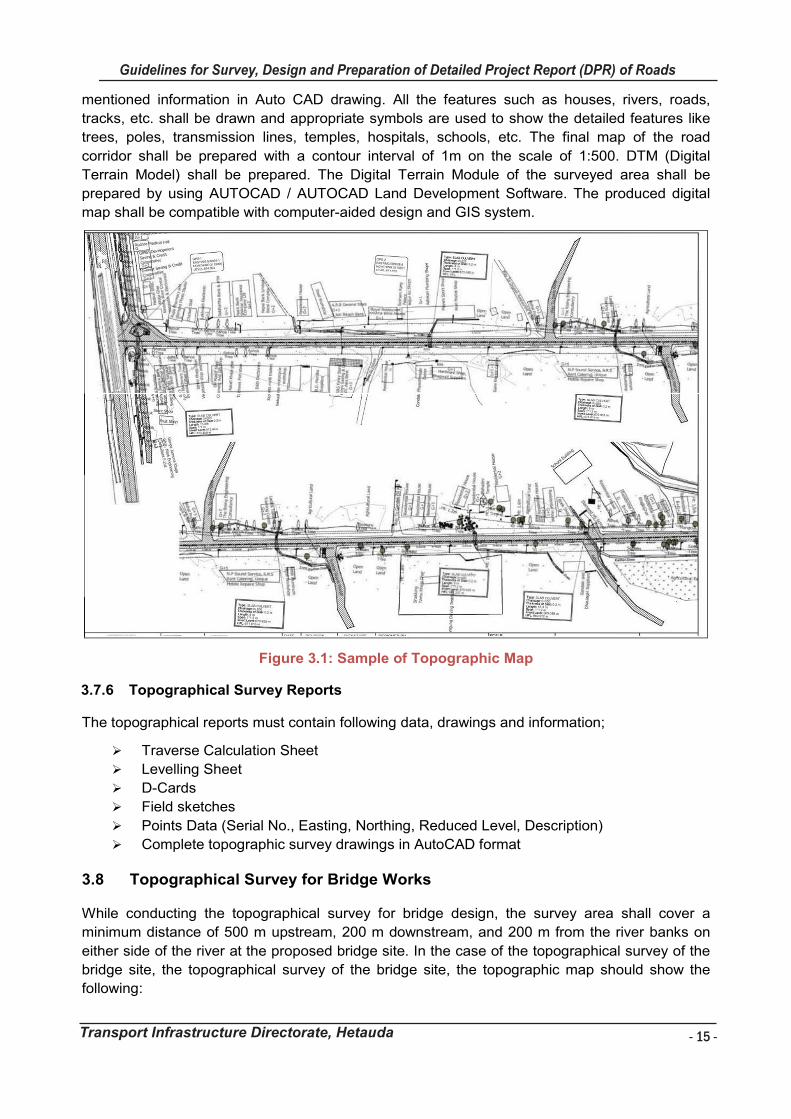
- 15 -
Guidelines for Survey, Design and Preparation of Detailed Project Report (DPR) of Roads
Transport Infrastructure Directorate, Hetauda
Guidelines for Survey Works Including Preparation of Detailed Project Report (DPR) of Roads
Transport Infrastructure Directorate, Hetauda 15
mentioned information in Auto CAD drawing. All the features such as houses, rivers, roads,
tracks, etc. shall be drawn and appropriate symbols are used to show the detailed features like
trees, poles, transmission lines, temples, hospitals, schools, etc. The final map of the road
corridor shall be prepared with a contour interval of 1m on the scale of 1:500. DTM (Digital
Terrain Model) shall be prepared. The Digital Terrain Module of the surveyed area shall be
prepared by using AUTOCAD / AUTOCAD Land Development Software. The produced digital
map shall be compatible with computer-aided design and GIS system.
Figure 3.1: Sample of Topographic Map
3.7.6 Topographical Survey Reports
The topographical reports must contain following data, drawings and information;
Traverse Calculation Sheet
Levelling Sheet
D-Cards
Field sketches
Points Data (Serial No., Easting, Northing, Reduced Level, Description)
Complete topographic survey drawings in AutoCAD format
Topographical Survey for Bridge Works 3.8
While conducting the topographical survey for bridge design, the survey area shall cover a
minimum distance of 500 m upstream, 200 m downstream, and 200 m from the river banks on
either side of the river at the proposed bridge site. In the case of the topographical survey of the
bridge site, the topographical survey of the bridge site, the topographic map should show the
following:
- 16 -
Guidelines for Survey, Design and Preparation of Detailed Project Report (DPR) of Roads
Transport Infrastructure Directorate, Hetauda
Guidelines for Survey Works Including Preparation of Detailed Project Report (DPR) of Roads
Transport Infrastructure Directorate, Hetauda 16
Contours at 1.0 m intervals in hilly area and at 0.25 m in plain area.
Flood lines on either side of the river in the entire area surveyed.
Lines with spot level along which the bed slope of the river is taken.
Both banks of the river
Lines along which the cross section of river is taken.
Details of government and /or public establishment on the river banks, details of
existing river training works (if any)
Traverse lines benchmark reference lines and /or points concerning which the present
topo map is prepared.
The angle and direction of skew, if the bridge is proposed to be aligned skew.
The names of the nearest identifiable villages/towns etc. in either ends of bridge
Other information relevant to the design, construction, and /or maintenance of the
bridge.
Drawing should show the following minimum scales:
• Site Plan 1 : 50,000
• Plan 1: 1,000
• Horizontal Profile 1 : 1,000
• Vertical Profile 1 : 200
• Cross sections 1:200
Differential Global Positioning System (DGPS) 3.9
Differential global positioning system (DGPS) is an enhancement to the global positioning
system that provides improved location accuracy, from the 15- meter nominal GPS accuracy to
about 10 cm in case of the best implementations. DGPS uses one or several (network) fixed
ground-based reference stations in known locations. DGPS components are the base receiver,
rover receiver.
A modification of the relative positioning method is the differential GPS (DGPS) technique, where
one of the two receivers observing simultaneously is equipped with a transmitter and the other
receiver(s) can receive the messages given by this transmitter. The transmitting receiver (Base
Station) is kept fixed on a point whose location is known to a high degree of accuracy. Based
upon this position, the receiver (Rover) computes corrections to the range/phase observations
from a GPS satellite and transmits them to the other receiver, which can apply these corrections
to improve the accuracy of its own position computed from GPS observations.
Methodology for Establishment of Base station / Control Points with DSPS
o Base Stations to be fixed by Multi/Dual-frequency DGPS receivers with Trig Control
Point of Government of Nepal as reference (to be supplied by Department of Survey).
o The minimum observation time for the base station shall be 3 hours.
o Required number of Control Points shall be established in such a way that the
distance between the DGPS base station & rover shall be less than 5 km.
o The panoramic view surrounding the Base Station as well as antenna location
showing the terrain nearby should be digitally photographed (should be taken in three
or four different directions) and documented.
o Rovers shall be of Dual/Multiple frequency DGPS receivers within a radius of 50 km
from the base. In case Single frequency DGPS receivers are used they should be
used within a 10 km radius only. Readings of the BMs shall be taken with a minimum
observation period of 1 hour.
Guidelines for Survey Works Including Preparation of Detailed Project Report (DPR) of Roads
Transport Infrastructure Directorate, Hetauda 17
Drone Survey 3.10
The Drone based survey is not a separate type of survey but it is a basic aerial photography
survey which has been used for many years to prepare topographical maps. Only difference is
the aircraft and the format of the aerial photo. The Drone survey flies at lower height e.g. 80 to
100m and takes digital photo at 12 to 50-megapixel resolution. Due to lower height and high-
resolution camera the resulting ortho-photo has very high resolution e.g. 3cm to 10cm.
A drone survey refers to the use of a drone, or unmanned aerial vehicle (UAV), to capture aerial
data with downward-facing sensors, such as RGB or multispectral cameras, and LIDAR
payloads. During a drone survey with an RGB camera, the ground is photographed several times
from different angles, and each image is tagged with coordinates.
With a drone, it is possible to carry out topographic surveys of the same quality as the highly
accurate measurements collected by traditional methods, but in a fraction of the time. This
substantially reduces the cost of a site survey and the workload of specialists in the field.
The primary outputs of the survey are:
High-resolution aerial images
A detailed map of the entire road section: high-resolution ortho-photo, contour maps of
1m contour intervals, and a complete top map.
Profile and cross-section maps at each chainage.
A web-based road inventory to store images and different outputs of the project
3.10.1 Benefits of Drone Survey
Reduce Field Time and Survey Costs
Capturing topographic data with a drone is up to five times faster than with land-based methods
and requires less manpower. This survey ultimately delivers your survey results faster and at a
lower cost.
Provide Accurate and Exhaustive Data
Total stations only measure individual points. One drone flight produces thousands of
measurements, which can be represented in different formats (orthomosaic, point cloud, DTM,
DSM, contour lines, etc). Each pixel of the produced map or point of the 3D model contains 3D
geo-data. Surveying drone solutions can produce surveys with different degrees of accuracy,
depending on the requirements of the project.
3.10.2 Methodology
Photos are taken with at least 85% frontal and at least 60% side overlaps to generate accurate
model. Structure from Motion (SFM) is used to calibrate the camera, generate automated tie
points, and dense point clouds. The ground controls points are established using professional
GPS systems to transform the point cloud to the true ground scale.
Ortho-Photo is prepared from the projected point clouds and DTM is prepared from classified
point cloud with ground surfaces (excluding building, structures and vegetation). The process is
more or less automatic from image processing to the generation of the Point Clouds, DEM, DTM
and ortho-photo. The drones with RTK (Real Time Kinematic) GPS facility even do not require
ground control points. The flow diagram mentioned below represents how drones are typically
integrated into surveying workflows:
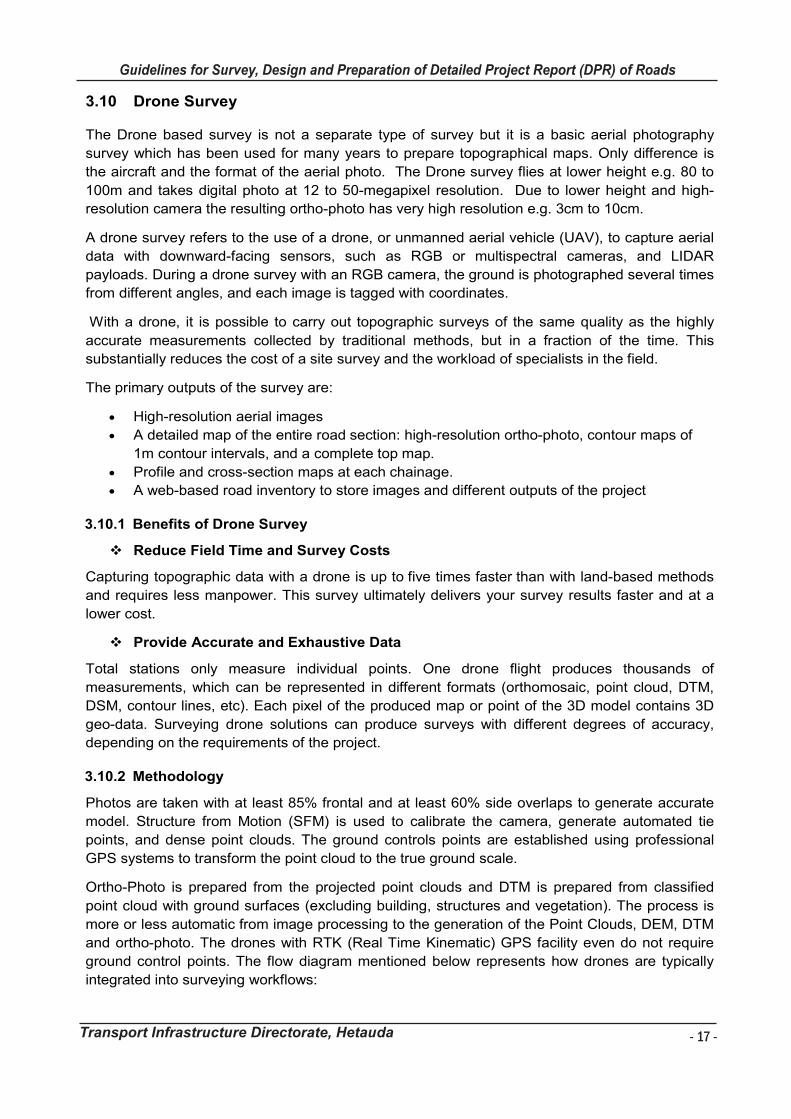
- 17 -
Guidelines for Survey, Design and Preparation of Detailed Project Report (DPR) of Roads
Transport Infrastructure Directorate, Hetauda
Guidelines for Survey Works Including Preparation of Detailed Project Report (DPR) of Roads
Transport Infrastructure Directorate, Hetauda 17
Drone Survey 3.10
The Drone based survey is not a separate type of survey but it is a basic aerial photography
survey which has been used for many years to prepare topographical maps. Only difference is
the aircraft and the format of the aerial photo. The Drone survey flies at lower height e.g. 80 to
100m and takes digital photo at 12 to 50-megapixel resolution. Due to lower height and high-
resolution camera the resulting ortho-photo has very high resolution e.g. 3cm to 10cm.
A drone survey refers to the use of a drone, or unmanned aerial vehicle (UAV), to capture aerial
data with downward-facing sensors, such as RGB or multispectral cameras, and LIDAR
payloads. During a drone survey with an RGB camera, the ground is photographed several times
from different angles, and each image is tagged with coordinates.
With a drone, it is possible to carry out topographic surveys of the same quality as the highly
accurate measurements collected by traditional methods, but in a fraction of the time. This
substantially reduces the cost of a site survey and the workload of specialists in the field.
The primary outputs of the survey are:
High-resolution aerial images
A detailed map of the entire road section: high-resolution ortho-photo, contour maps of
1m contour intervals, and a complete top map.
Profile and cross-section maps at each chainage.
A web-based road inventory to store images and different outputs of the project
3.10.1 Benefits of Drone Survey
Reduce Field Time and Survey Costs
Capturing topographic data with a drone is up to five times faster than with land-based methods
and requires less manpower. This survey ultimately delivers your survey results faster and at a
lower cost.
Provide Accurate and Exhaustive Data
Total stations only measure individual points. One drone flight produces thousands of
measurements, which can be represented in different formats (orthomosaic, point cloud, DTM,
DSM, contour lines, etc). Each pixel of the produced map or point of the 3D model contains 3D
geo-data. Surveying drone solutions can produce surveys with different degrees of accuracy,
depending on the requirements of the project.
3.10.2 Methodology
Photos are taken with at least 85% frontal and at least 60% side overlaps to generate accurate
model. Structure from Motion (SFM) is used to calibrate the camera, generate automated tie
points, and dense point clouds. The ground controls points are established using professional
GPS systems to transform the point cloud to the true ground scale.
Ortho-Photo is prepared from the projected point clouds and DTM is prepared from classified
point cloud with ground surfaces (excluding building, structures and vegetation). The process is
more or less automatic from image processing to the generation of the Point Clouds, DEM, DTM
and ortho-photo. The drones with RTK (Real Time Kinematic) GPS facility even do not require
ground control points. The flow diagram mentioned below represents how drones are typically
integrated into surveying workflows:
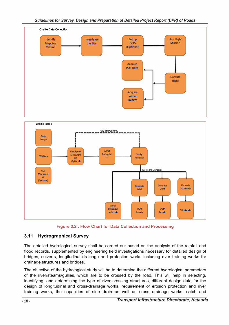
- 18 -
Guidelines for Survey, Design and Preparation of Detailed Project Report (DPR) of Roads
Transport Infrastructure Directorate, Hetauda
Guidelines for Survey Works Including Preparation of Detailed Project Report (DPR) of Roads
Transport Infrastructure Directorate, Hetauda 18
Figure 3.2 : Flow Chart for Data Collection and Processing
Hydrographical Survey 3.11
The detailed hydrological survey shall be carried out based on the analysis of the rainfall and
flood records, supplemented by engineering field investigations necessary for detailed design of
bridges, culverts, longitudinal drainage and protection works including river training works for
drainage structures and bridges.
The objective of the hydrological study will be to determine the different hydrological parameters
of the river/steams/gullies, which are to be crossed by the road. This will help in selecting,
identifying, and determining the type of river crossing structures, different design data for the
design of longitudinal and cross-drainage works, requirement of erosion protection and river
training works, the capacities of side drain as well as cross drainage works, catch and
Guidelines for Survey Works Including Preparation of Detailed Project Report (DPR) of Roads
Transport Infrastructure Directorate, Hetauda 19
subsurface drains, etc. For these tasks, all relevant data and meteorological records shall be
assembled to enable the necessary hydrological calculations (design discharge, required
span/openings, scour depth, high flood levels, etc) and assessments of drainage requirements
along the proposed roads and bridges.
For the determination of design data of bridge, detailed hydrometrical survey and hydrological
study of the river and bridge site shall be performed and include the following:
Catchment area of the river up to bridge site.
Length of the river from origin up to bridge site.
Possibility of change of catchment.
Nature, size and quantities of debris carried by the river.
Intensity, duration and distribution of rain in the catchment
Vegetation, cultivation etc. of the catchment
Existence of reservoir’s, Lakes in the catchment
Existing bridge or other hydraulic structures across the river in the vicinity of the
proposed bridge site with their details as much as possible.
General slope of the river from the critical point (origin) of the river up to bridge
site and general slope of the catchment in both sides of the river.
Cross sections covering 200 m beyond flood lines of the river at proposed bridge
site, at about 500 m u/s and about 200 m d/s. Wherein HFL, LWL, LBL, area of
the cross section, wetted perimeter and geological profile with silt factor of each
strata (at proposed bridge site only ) shall be indicated. (Horizontal and vertical
scale of the cross section shall be the same.)
Bed slope of the river which must start from 100 m up of the U/S cross section
and end at 100 m down of d/s cross section.
Maximum discharge calculated by established formulas with different return
periods and the peak discharge observed over a period of 100 years.
Velocity and depth of flow at the time of survey.
Shifting of the river in the past at proposed bridge site and in its vicinity.
Other information required for rive control, design, construction and maintenance
of bridge.
Geological and Geotechnical Survey 3.12
3.12.1 Engineering Geological Survey
In hilly and mountainous terrain, engineering geological investigations need thorough detailed
study. The main objectives of the study are to identify those geological and geo-morphological
conditions present in the region, as well as site-specific issues, which may have a direct bearing
on the location, design, and operational aspects of the roads and the road allied structures.
Engineering geological studies shall be carried out using simple hand-held instruments, eg:
Brenton compasses, altimeters, geological hammers, measuring tapes, Abney levels, etc.
Engineering geologic field survey shall include mapping on the topographic base map of the
different parameters of the State of Nature and of the Danger. These will include the followings:
rock types, including weathering state
soil type (Generic and Unified Soil Classification) and soil thickness
rock structures (bedding plane, joint, foliation, cleavage, fault, fold, sheer faces)
- 19 -
Guidelines for Survey, Design and Preparation of Detailed Project Report (DPR) of Roads
Transport Infrastructure Directorate, Hetauda
Guidelines for Survey Works Including Preparation of Detailed Project Report (DPR) of Roads
Transport Infrastructure Directorate, Hetauda 19
subsurface drains, etc. For these tasks, all relevant data and meteorological records shall be
assembled to enable the necessary hydrological calculations (design discharge, required
span/openings, scour depth, high flood levels, etc) and assessments of drainage requirements
along the proposed roads and bridges.
For the determination of design data of bridge, detailed hydrometrical survey and hydrological
study of the river and bridge site shall be performed and include the following:
Catchment area of the river up to bridge site.
Length of the river from origin up to bridge site.
Possibility of change of catchment.
Nature, size and quantities of debris carried by the river.
Intensity, duration and distribution of rain in the catchment
Vegetation, cultivation etc. of the catchment
Existence of reservoir’s, Lakes in the catchment
Existing bridge or other hydraulic structures across the river in the vicinity of the
proposed bridge site with their details as much as possible.
General slope of the river from the critical point (origin) of the river up to bridge
site and general slope of the catchment in both sides of the river.
Cross sections covering 200 m beyond flood lines of the river at proposed bridge
site, at about 500 m u/s and about 200 m d/s. Wherein HFL, LWL, LBL, area of
the cross section, wetted perimeter and geological profile with silt factor of each
strata (at proposed bridge site only ) shall be indicated. (Horizontal and vertical
scale of the cross section shall be the same.)
Bed slope of the river which must start from 100 m up of the U/S cross section
and end at 100 m down of d/s cross section.
Maximum discharge calculated by established formulas with different return
periods and the peak discharge observed over a period of 100 years.
Velocity and depth of flow at the time of survey.
Shifting of the river in the past at proposed bridge site and in its vicinity.
Other information required for rive control, design, construction and maintenance
of bridge.
Geological and Geotechnical Survey 3.12
3.12.1 Engineering Geological Survey
In hilly and mountainous terrain, engineering geological investigations need thorough detailed
study. The main objectives of the study are to identify those geological and geo-morphological
conditions present in the region, as well as site-specific issues, which may have a direct bearing
on the location, design, and operational aspects of the roads and the road allied structures.
Engineering geological studies shall be carried out using simple hand-held instruments, eg:
Brenton compasses, altimeters, geological hammers, measuring tapes, Abney levels, etc.
Engineering geologic field survey shall include mapping on the topographic base map of the
different parameters of the State of Nature and of the Danger. These will include the followings:
rock types, including weathering state
soil type (Generic and Unified Soil Classification) and soil thickness
rock structures (bedding plane, joint, foliation, cleavage, fault, fold, sheer faces)
- 20 -
Guidelines for Survey, Design and Preparation of Detailed Project Report (DPR) of Roads
Transport Infrastructure Directorate, Hetauda
Guidelines for Survey Works Including Preparation of Detailed Project Report (DPR) of Roads
Transport Infrastructure Directorate, Hetauda 20
Hydro-geologic conditions (drainage pattern and drainage characteristics, springs and
seepage, and their discharge). Dry seed holes will also be mapped.
Slope characteristics inclination, irregularities, breaks, hummocky topography, cliffs,
escarpments, etc.
Landslide (classification and geometry)
Erosion (type and extent) and debris flow areas etc.
All the field observations will be recorded in a standard format using the MRE prescribed form
with necessary improvements. The format of data collection for Geological and Soil Stability is in
Appendix IX.
3.12.2 Geo-technical Survey
Geo-technical investigations and sub-surface explorations for the proposed road and bridges
shall be carried out for the proper design of the works and conduct all relevant laboratory and
field tests on soil and rock samples.
The investigation and testing works for road works will comprise mainly of investigation of sub-
grade and the main objective will be to determine the general and strength properties of sub-
grade soil and to decide the sub-grade characteristics for pavement design. The sub-grade
investigation for road works will involve:
Dynamic Cone Penetrometer (DCP) Tests
Dynamic Cone Penetrometer tests shall be undertaken for the entire road length sections in
order to establish the strength of the subgrade. The DCP tests will be undertaken normally at an
interval of approximately 500 m or as required. Test shall be started from subgrade level and it
will be continued to 1 m depth from the test level. An 8 kg hammer and 10 mm cone will be used
and rate of penetration against each blow shall be measured. The results shall be analysed in
order to calculate the Field CBR of the subgrade at each test location.
Principles of DCP
DCP is an instrument designed for the rapid in situ measurement of the structural
properties of existing sub grade condition.
Continuous measurement can be made to a depth of 800 mm. Measurement is possible
to a depth of 1200 mm if an extension is fitted.
The underlying principle of the DCP is the rate of penetration of the cone, when driven by
a standard force, is inversely related to the strength of material as measured.
The basic principle involved in the operation of this apparatus is the measuring of the
resistance offered by the pavement layers to the penetration of a standard cone with a
diameter of 20 mm (with 600 apex angle) driven by an 8 kg hammer freely falling through
a height of 575 mm. the amount of penetration (in mm) of the cone is generally reported
in terms of the average penetration per blow, (mm/blow).
Guidelines for Survey Works Including Preparation of Detailed Project Report (DPR) of Roads
Transport Infrastructure Directorate, Hetauda 21
Apparatus/ Equipment
A complete set of TRL DCP instrument and its accessories is shown below:
Figure 3.3 : A complete set of TRL DCP instrument
Procedure
Three operators are required for carrying out this test. One to hold instrument, one to
raise and drop the weight and a technician to record the results.
Hold the instrument vertically and raised the weight carefully to handle.
Care should be taken to ensure that the weight touches the handle, but does not lift the
instrument.
Before it is allowed to drop the operators should let weight fall freely without lowering it
with his hands.
Record the initial reading on the dynamic cone penetrometer scale.
Calculate the value of penetration (in mm) for each blow by subtracting the previous
recorded reading (i.e. reading on scale) from the current reading.
Calculate the cumulative depth of penetration (in mm) for each blow by adding all the
previous individual depth of penetrations.
Determine the rate of penetration (mm/blow)
Use the following formula for calculating the CBR value.
log10CBR = 2.48 – 1.057 log10 (mm/blow)
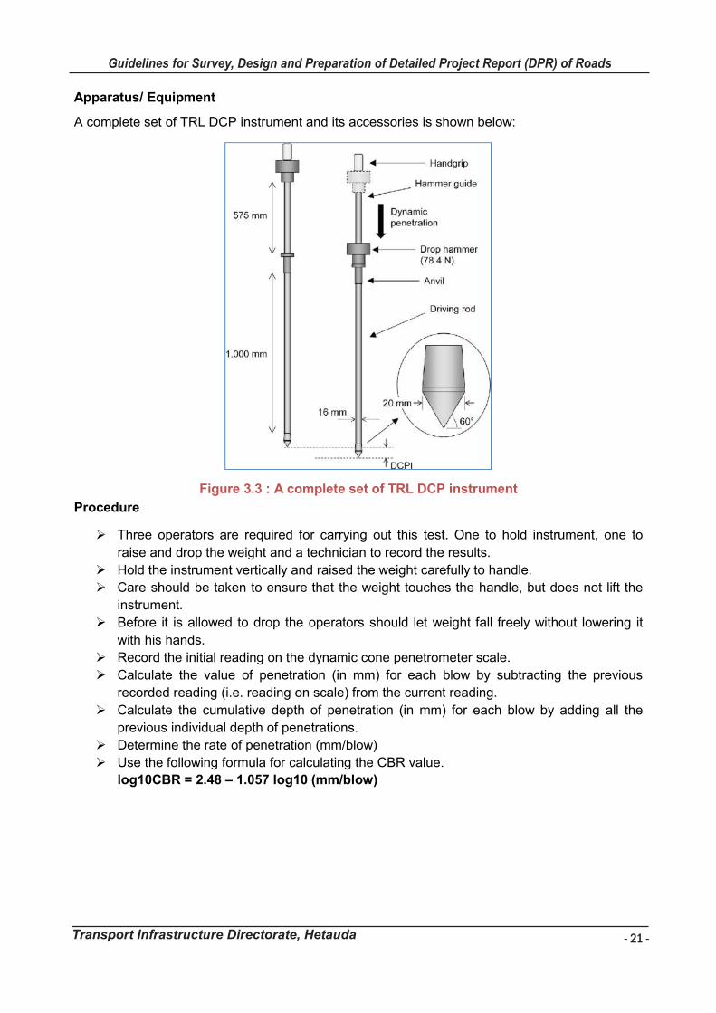
- 21 -
Guidelines for Survey, Design and Preparation of Detailed Project Report (DPR) of Roads
Transport Infrastructure Directorate, Hetauda
Guidelines for Survey Works Including Preparation of Detailed Project Report (DPR) of Roads
Transport Infrastructure Directorate, Hetauda 21
Apparatus/ Equipment
A complete set of TRL DCP instrument and its accessories is shown below:
Figure 3.3 : A complete set of TRL DCP instrument
Procedure
Three operators are required for carrying out this test. One to hold instrument, one to
raise and drop the weight and a technician to record the results.
Hold the instrument vertically and raised the weight carefully to handle.
Care should be taken to ensure that the weight touches the handle, but does not lift the
instrument.
Before it is allowed to drop the operators should let weight fall freely without lowering it
with his hands.
Record the initial reading on the dynamic cone penetrometer scale.
Calculate the value of penetration (in mm) for each blow by subtracting the previous
recorded reading (i.e. reading on scale) from the current reading.
Calculate the cumulative depth of penetration (in mm) for each blow by adding all the
previous individual depth of penetrations.
Determine the rate of penetration (mm/blow)
Use the following formula for calculating the CBR value.
log10CBR = 2.48 – 1.057 log10 (mm/blow)
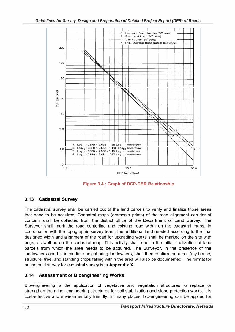
- 22 -
Guidelines for Survey, Design and Preparation of Detailed Project Report (DPR) of Roads
Transport Infrastructure Directorate, Hetauda
Guidelines for Survey Works Including Preparation of Detailed Project Report (DPR) of Roads
Transport Infrastructure Directorate, Hetauda 22
Figure 3.4 : Graph of DCP-CBR Relationship
Cadastral Survey 3.13
The cadastral survey shall be carried out of the land parcels to verify and finalize those areas
that need to be acquired. Cadastral maps (ammonia prints) of the road alignment corridor of
concern shall be collected from the district office of the Department of Land Survey. The
Surveyor shall mark the road centerline and existing road width on the cadastral maps. In
coordination with the topographic survey team, the additional land needed according to the final
designed width and alignment of the road for upgrading works shall be marked on the site with
pegs, as well as on the cadastral map. This activity shall lead to the initial finalization of land
parcels from which the area needs to be acquired. The Surveyor, in the presence of the
landowners and his immediate neighboring landowners, shall then confirm the area. Any house,
structure, tree, and standing crops falling within the area will also be documented. The format for
house hold survey for cadastral survey is in Appendix X.
Assessment of Bioengineering Works 3.14
Bio-engineering is the application of vegetative and vegetation structures to replace or
strengthen the minor engineering structures for soil stabilization and slope protection works. It is
cost-effective and environmentally friendly. In many places, bio-engineering can be applied for
Guidelines for Survey Works Including Preparation of Detailed Project Report (DPR) of Roads
Transport Infrastructure Directorate, Hetauda 23
the beautification of the roadside development. There are different planting configurations, the
choice of which will depend on different factors. Choice of species of vegetation should
adequately address engineering, physical, biological, and social factors.
The sites for the application of bio-engineering methods shall be analyzed by a process of
prioritization, appraisal, and characterization. Possible danger to the road, to its associated
drainage and other structures as well as the danger to neighboring land and environmental
degradation, shall also be assessed thoroughly. Hence, for the design of the most suitable and
appropriate bio-engineering measures, first shall prepare a Bio-engineering Map of the road
corridor by undertaking field surveys and by using information from the Engineering
Geologist/Geotechnical Engineer, Highway Design Engineer, and the Structural Engineer.
This map shall be a schematic diagram in which the features of the road corridor shall be shown
such as attitude, topographical features, slope angle, and slope type, soil type, site moisture
(wet, moist, dry, seasonality), drainage characteristics, groundwater, causing increased pore
pressure, surface erosion (sheet erosion, gully erosion, piping, and slide, etc.) land river bank
cuttings, cultivation practice, type and characteristics of indigenous quick-growing local pants
and species, indigenous method and practice of vegetation, possibilities of planting fuel and
fodder trees, etc. Nurseries developed in the vicinity of the project area, if any, will be inspected;
the type, characteristics, available stock of plants and species will be noted.
Using all the above information and field findings, the sites for bio-engineering application shall
be finalized in conjunction with Engineering Geological/Geotechnical Engineer, Structural and
Highway Engineer. Different possible alternatives and their combination shall also be identified
for each site and reflected into the Bio-engineering map.
Traffic Surveys 3.15
Information about traffic is vital for road project since it would form the basis for the classification
of road, design of the pavement, fixing the number of traffic lanes, design of intersections and
economic appraisal of the project. Traffic surveys required to be conducted in connection with
the preparation of road project are as under:
a. Classified Traffic Volume Counts
b. Origin-Destination Surveys
c. Speed and delay studies
d. Traffic Survey for the Design of Road Junction
e. Axle Load Surveys
f. Accident Records
3.15.1 Classified Traffic Volume Counts
The main objective of the traffic survey is to determine the traffic volume with vehicle
classifications suitable for pavement design. It requires an estimate of the annual average daily
traffic (with vehicle classification), which shall be based on manual classified volume counts and
historical traffic data. The classified counts shall be done for seven days and a full 24 hours at
important locations and one day period ranging from 16 hours to 24 hours at other locations. The
daily and hourly variations shall be analyzed and used from the 24 hours; seven days counts
locations. Standard count forms will be used and the results screened to ensure accuracy. Using
the classified volume count information, together with historic traffic data such as the daily and
seasonal variations, derived from the survey and previous studies, the current level of traffic will
be determined for each section of the project roads. Future traffic levels shall then be
- 23 -
Guidelines for Survey, Design and Preparation of Detailed Project Report (DPR) of Roads
Transport Infrastructure Directorate, Hetauda
Guidelines for Survey Works Including Preparation of Detailed Project Report (DPR) of Roads
Transport Infrastructure Directorate, Hetauda 23
the beautification of the roadside development. There are different planting configurations, the
choice of which will depend on different factors. Choice of species of vegetation should
adequately address engineering, physical, biological, and social factors.
The sites for the application of bio-engineering methods shall be analyzed by a process of
prioritization, appraisal, and characterization. Possible danger to the road, to its associated
drainage and other structures as well as the danger to neighboring land and environmental
degradation, shall also be assessed thoroughly. Hence, for the design of the most suitable and
appropriate bio-engineering measures, first shall prepare a Bio-engineering Map of the road
corridor by undertaking field surveys and by using information from the Engineering
Geologist/Geotechnical Engineer, Highway Design Engineer, and the Structural Engineer.
This map shall be a schematic diagram in which the features of the road corridor shall be shown
such as attitude, topographical features, slope angle, and slope type, soil type, site moisture
(wet, moist, dry, seasonality), drainage characteristics, groundwater, causing increased pore
pressure, surface erosion (sheet erosion, gully erosion, piping, and slide, etc.) land river bank
cuttings, cultivation practice, type and characteristics of indigenous quick-growing local pants
and species, indigenous method and practice of vegetation, possibilities of planting fuel and
fodder trees, etc. Nurseries developed in the vicinity of the project area, if any, will be inspected;
the type, characteristics, available stock of plants and species will be noted.
Using all the above information and field findings, the sites for bio-engineering application shall
be finalized in conjunction with Engineering Geological/Geotechnical Engineer, Structural and
Highway Engineer. Different possible alternatives and their combination shall also be identified
for each site and reflected into the Bio-engineering map.
Traffic Surveys 3.15
Information about traffic is vital for road project since it would form the basis for the classification
of road, design of the pavement, fixing the number of traffic lanes, design of intersections and
economic appraisal of the project. Traffic surveys required to be conducted in connection with
the preparation of road project are as under:
a. Classified Traffic Volume Counts
b. Origin-Destination Surveys
c. Speed and delay studies
d. Traffic Survey for the Design of Road Junction
e. Axle Load Surveys
f. Accident Records
3.15.1 Classified Traffic Volume Counts
The main objective of the traffic survey is to determine the traffic volume with vehicle
classifications suitable for pavement design. It requires an estimate of the annual average daily
traffic (with vehicle classification), which shall be based on manual classified volume counts and
historical traffic data. The classified counts shall be done for seven days and a full 24 hours at
important locations and one day period ranging from 16 hours to 24 hours at other locations. The
daily and hourly variations shall be analyzed and used from the 24 hours; seven days counts
locations. Standard count forms will be used and the results screened to ensure accuracy. Using
the classified volume count information, together with historic traffic data such as the daily and
seasonal variations, derived from the survey and previous studies, the current level of traffic will
be determined for each section of the project roads. Future traffic levels shall then be
- 24 -
Guidelines for Survey, Design and Preparation of Detailed Project Report (DPR) of Roads
Transport Infrastructure Directorate, Hetauda
Guidelines for Survey Works Including Preparation of Detailed Project Report (DPR) of Roads
Transport Infrastructure Directorate, Hetauda 24
determined from the information on growth rates for the normal traffic, generated traffic, and
diverted traffic.
The format of manual traffic count survey is given in Appendix XI.
3.15.2 Axle Load Survey
The objective of the axle load survey is to quantify the damage that any vehicle type will cause to
the road. It requires an estimate to be made of the average equivalence factor per each type of
commercial vehicle using the road, which shall be based on 24 hours axle load surveys of
commercial following the procedure set out in IRC guidelines. This survey will record not only the
axle loads of vehicles but also; loaded or empty state; origin-destination; and cargo type. The
axle load data will be analyzed to calculate the equivalency factor (number of standard 10.2 t
axles) for each class of commercial vehicle, thus providing the current level of axle loading on
the project road. The equivalency factors used in or derived from other studies will be reviewed
and analyzed. Care shall be taken to finalize the equivalency factor of each.
In the absence of axle survey work, the survey data together with axle load information from
previous studies can be used if available. The Government has adopted a legal axle load limit of
10.2 tons per standard axle type of commercial vehicle because it will affect to great extent in the
design thickness of the pavement.
The format of Axle load survey is given in Appendix XII.
3.15.3 Accident Records
If accident records are maintained in a methodological manner, they form a good basis for
designing the improvements at accident-prone locations on existing roads. Such records, if
available, should invariably be consulted before deciding the improvements.
3.15.4 Traffic Projections
Traffic counts would provide information about present traffic on the road (in the case of existing
roads), or the possible diverted traffic (in the case of new construction, such as bypass). For
design purpose, however it is necessary that classified traffic should be predicted for the future
perspective year for which the facility is to be designed.
Period of projection depends on the type of project, importance of the road, availability of finance
and other related factors. The desirable and minimum forecast periods is 20 years for provincial
roads.
Traffic growth should be assessed in the first instance on the basis of observed trend of traffic in
the recent years and other economic indicators. In this connection the Pavement Design
Guideline by Department of Road (DOR) shall be followed for traffic projection.
Material Availability Survey 3.16
The material availability survey and study shall be carried out. It shall determine the quantity and
quality of the materials required for construction. The availability of the necessary materials shall
be surveyed to determine the following:
Information for the manufactured materials such as cement, steel, fuel, timber, bitumen,
etc. will be collected from the potential and prospective importers and suppliers in terms
of quality, quantity, and costs.
Guidelines for Survey Works Including Preparation of Detailed Project Report (DPR) of Roads
Transport Infrastructure Directorate, Hetauda 25
Natural occurring material sources such as stone quarries, sand, aggregates, and fill
material borrow areas, and water sources will be identified and investigated for quality
and quantity.
All potential quarry sites/borrow areas to evaluate the composition of deposition and
quantities. Bulk samples of the materials encountered shall be collected for laboratory
testing (natural moisture content, gradation, water absorption, unit weight, CBR, Los
Angeles, flakiness index, Aggregate Crushing Value )
The lead distances of the source from road alignment, base price, and royalties, etc. at
the source will also be enquired and recorded for use in cost estimations.
Possible environmental impacts due to the extraction of construction materials and their
mitigation measures will also be assessed.
The format for collection of information on quarry sites near the road alignment is in Appendix
XIII.

- 25 -
Guidelines for Survey, Design and Preparation of Detailed Project Report (DPR) of Roads
Transport Infrastructure Directorate, Hetauda
Guidelines for Survey Works Including Preparation of Detailed Project Report (DPR) of Roads
Transport Infrastructure Directorate, Hetauda 25
Natural occurring material sources such as stone quarries, sand, aggregates, and fill
material borrow areas, and water sources will be identified and investigated for quality
and quantity.
All potential quarry sites/borrow areas to evaluate the composition of deposition and
quantities. Bulk samples of the materials encountered shall be collected for laboratory
testing (natural moisture content, gradation, water absorption, unit weight, CBR, Los
Angeles, flakiness index, Aggregate Crushing Value )
The lead distances of the source from road alignment, base price, and royalties, etc. at
the source will also be enquired and recorded for use in cost estimations.
Possible environmental impacts due to the extraction of construction materials and their
mitigation measures will also be assessed.
The format for collection of information on quarry sites near the road alignment is in Appendix
XIII.
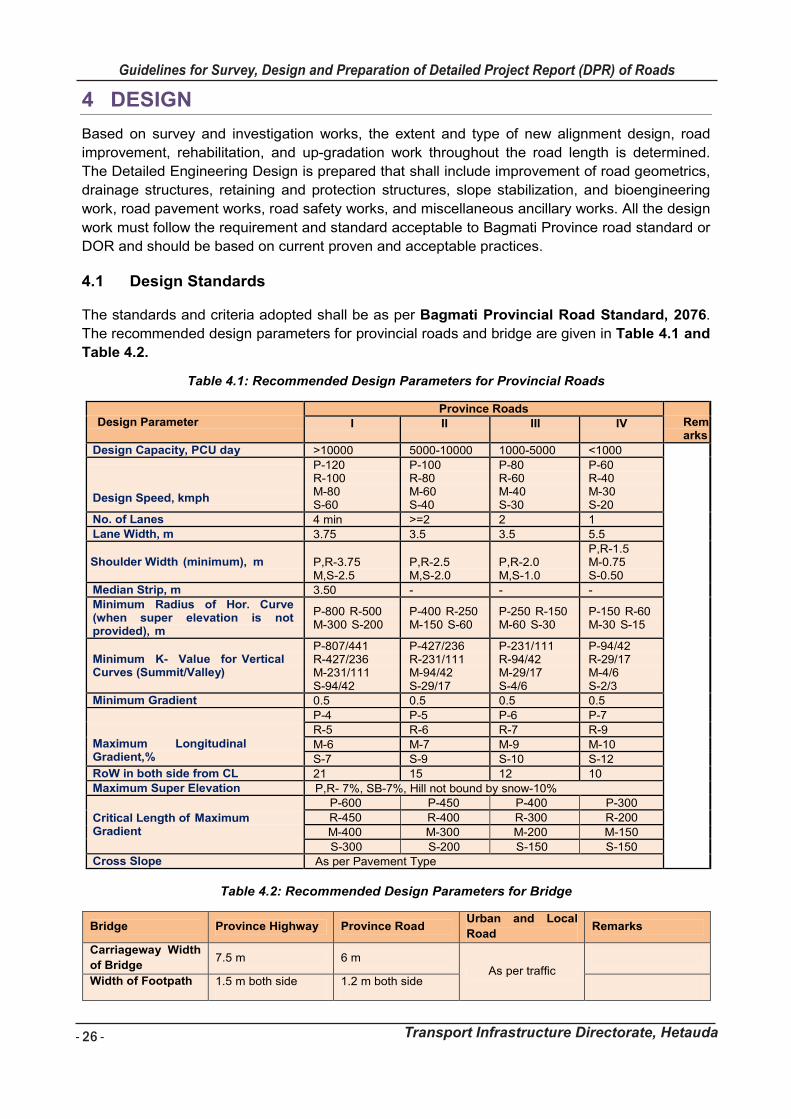
- 26 -
Guidelines for Survey, Design and Preparation of Detailed Project Report (DPR) of Roads
Transport Infrastructure Directorate, Hetauda
Guidelines for Survey Works Including Preparation of Detailed Project Report (DPR) of Roads
Transport Infrastructure Directorate, Hetauda 26
4 DESIGN
Based on survey and investigation works, the extent and type of new alignment design, road
improvement, rehabilitation, and up-gradation work throughout the road length is determined.
The Detailed Engineering Design is prepared that shall include improvement of road geometrics,
drainage structures, retaining and protection structures, slope stabilization, and bioengineering
work, road pavement works, road safety works, and miscellaneous ancillary works. All the design
work must follow the requirement and standard acceptable to Bagmati Province road standard or
DOR and should be based on current proven and acceptable practices.
Design Standards 4.1
The standards and criteria adopted shall be as per Bagmati Provincial Road Standard, 2076.
The recommended design parameters for provincial roads and bridge are given in Table 4.1 and
Table 4.2.
Table 4.1: Recommended Design Parameters for Provincial Roads
Design Parameter
Province Roads Remarks
I II III IV
Design Capacity, PCU day >10000 5000-10000 1000-5000 <1000
Design Speed, kmph
P-120 R-100 M-80 S-60
P-100 R-80 M-60 S-40
P-80 R-60 M-40 S-30
P-60 R-40 M-30 S-20
No. of Lanes 4 min >=2 2 1 Lane Width, m 3.75 3.5 3.5 5.5
Shoulder Width (minimum), m P,R-3.75 M,S-2.5
P,R-2.5 M,S-2.0
P,R-2.0 M,S-1.0
P,R-1.5 M-0.75 S-0.50
Median Strip, m 3.50 - - - Minimum Radius of Hor. Curve (when super elevation is not provided), m
P-800 R-500 M-300 S-200
P-400 R-250 M-150 S-60
P-250 R-150 M-60 S-30
P-150 R-60 M-30 S-15
Minimum K- Value for Vertical Curves (Summit/Valley)
P-807/441 R-427/236 M-231/111 S-94/42
P-427/236 R-231/111 M-94/42 S-29/17
P-231/111 R-94/42 M-29/17 S-4/6
P-94/42 R-29/17 M-4/6 S-2/3
Minimum Gradient 0.5 0.5 0.5 0.5
Maximum Longitudinal Gradient,%
P-4 P-5 P-6 P-7
R-5 R-6 R-7 R-9
M-6 M-7 M-9 M-10
S-7 S-9 S-10 S-12 RoW in both side from CL 21 15 12 10 Maximum Super Elevation P,R- 7%, SB-7%, Hill not bound by snow-10%
Critical Length of Maximum Gradient
P-600 P-450 P-400 P-300
R-450 R-400 R-300 R-200
M-400 M-300 M-200 M-150
S-300 S-200 S-150 S-150 Cross Slope As per Pavement Type
Table 4.2: Recommended Design Parameters for Bridge
Bridge Province Highway Province Road Urban and Local
Road Remarks
Carriageway Width
of Bridge 7.5 m 6 m
As per traffic
Width of Footpath 1.5 m both side 1.2 m both side
Guidelines for Survey Works Including Preparation of Detailed Project Report (DPR) of Roads
Transport Infrastructure Directorate, Hetauda 27
Engineering Design 4.2
4.2.1 Interactive Design Environment
All the design works shall be carried out using an Interactive Design Environment such that the
changes in the plan, profile, and cross-sections are instantly updated. Initially the Centre line
alignment will be created from the corridor mapping to match the existing road widths. The cross-
sections at required intervals and profile will be generated from the Triangulated Irregular
Network (TIN) model. The interactive environment provides a lot of benefits which include trial
design, selection of appropriate structures and continuity check, placement of the cross-drainage
structures, checking off the drain invert levels epically at the hairpin bends. Road alignment
designed on Digital Terrain Model (DTM) shall be set out at the site with staking the central line
and taking levels with verification of the design.
4.2.2 Geometric and Cross-Section Design
The detailed design of geometric elements shall cover mainly the major aspects of horizontal
alignment, longitudinal profile, cross-sectional elements, junctions, and intersections. These road
geometric elements shall be designed following project road design standards. Design of the
road geometrics shall be carried out by using internationally and nationally acceptable software
such as SOFTWELL, SMART Road etc. This is windows based software and the output can be
exported to AutoCAD and Microsoft Excel. All the design works shall be done by extensive
utilization of Computer-Aided Design software for the highest accuracy and quality of work, as
well as to complete the work in the specified limited time.
4.2.3 Design of Extra Widening, and Super Elevation
All the extra-widening works shall be calculated and must be included in the plan and cross-
section itself rather than leaving it for the construction stage. The extra-widening placement i.e.
inner or outer or mixed will be decided for each of the curves and the rate of extra widening will
be according to agreed design criteria. Precise super-elevation design including the chainage-
wise values shall be prepared. The complex nature of the hill road shall be carefully incorporated
in the super-elevation design works.
4.2.4 Design of Retaining Structures
Various types of retaining structures shall be designed and included in the cross-section. All the
retaining structures shall not only be shown in the cross-section but also be shown in the plan
and profile. A three-dimensional view of the structure shall also be generated and the quantity
extracted accordingly rather than from the cross-section. This method provides a more accurate
method of retaining quantity estimation which takes into account of the total volume rather than
the areas in each cross-section. The retaining structures up to 10 m height can be designed from
the Standard Drawing for Road Elements Published by DOR.
Figure 4.1 : Example of Cross-Section Editing with Structures and Drains
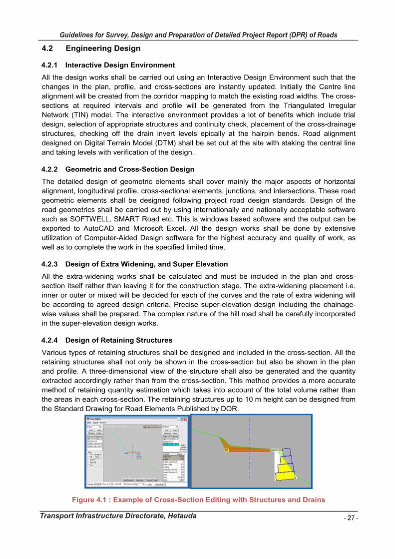
- 27 -
Guidelines for Survey, Design and Preparation of Detailed Project Report (DPR) of Roads
Transport Infrastructure Directorate, Hetauda
Guidelines for Survey Works Including Preparation of Detailed Project Report (DPR) of Roads
Transport Infrastructure Directorate, Hetauda 27
Engineering Design 4.2
4.2.1 Interactive Design Environment
All the design works shall be carried out using an Interactive Design Environment such that the
changes in the plan, profile, and cross-sections are instantly updated. Initially the Centre line
alignment will be created from the corridor mapping to match the existing road widths. The cross-
sections at required intervals and profile will be generated from the Triangulated Irregular
Network (TIN) model. The interactive environment provides a lot of benefits which include trial
design, selection of appropriate structures and continuity check, placement of the cross-drainage
structures, checking off the drain invert levels epically at the hairpin bends. Road alignment
designed on Digital Terrain Model (DTM) shall be set out at the site with staking the central line
and taking levels with verification of the design.
4.2.2 Geometric and Cross-Section Design
The detailed design of geometric elements shall cover mainly the major aspects of horizontal
alignment, longitudinal profile, cross-sectional elements, junctions, and intersections. These road
geometric elements shall be designed following project road design standards. Design of the
road geometrics shall be carried out by using internationally and nationally acceptable software
such as SOFTWELL, SMART Road etc. This is windows based software and the output can be
exported to AutoCAD and Microsoft Excel. All the design works shall be done by extensive
utilization of Computer-Aided Design software for the highest accuracy and quality of work, as
well as to complete the work in the specified limited time.
4.2.3 Design of Extra Widening, and Super Elevation
All the extra-widening works shall be calculated and must be included in the plan and cross-
section itself rather than leaving it for the construction stage. The extra-widening placement i.e.
inner or outer or mixed will be decided for each of the curves and the rate of extra widening will
be according to agreed design criteria. Precise super-elevation design including the chainage-
wise values shall be prepared. The complex nature of the hill road shall be carefully incorporated
in the super-elevation design works.
4.2.4 Design of Retaining Structures
Various types of retaining structures shall be designed and included in the cross-section. All the
retaining structures shall not only be shown in the cross-section but also be shown in the plan
and profile. A three-dimensional view of the structure shall also be generated and the quantity
extracted accordingly rather than from the cross-section. This method provides a more accurate
method of retaining quantity estimation which takes into account of the total volume rather than
the areas in each cross-section. The retaining structures up to 10 m height can be designed from
the Standard Drawing for Road Elements Published by DOR.
Figure 4.1 : Example of Cross-Section Editing with Structures and Drains
- 28 -
Guidelines for Survey, Design and Preparation of Detailed Project Report (DPR) of Roads
Transport Infrastructure Directorate, Hetauda
Guidelines for Survey Works Including Preparation of Detailed Project Report (DPR) of Roads
Transport Infrastructure Directorate, Hetauda 28
4.2.5 Design of Pavements
The design of pavement shall be done using DOR Pavement Design Guidelines, 2021 for a
period of 20 years. The design alternatives in some selected reaches, mostly in the urban area,
high gradient sections and hairpin bends shall be investigated both for rigid and flexible
pavement design options to avoid the deterioration of pavement due to drainage problems.
For the design of the new pavement / paved shoulder, each set of design input will be decided
based on rigorous testing and evaluation of its suitability and relevance in respect of the in-
service performance of the pavement. Values of various design inputs criteria will be carefully
chosen taking into consideration to the local practice and conditions. The pavement design task
will also cover working out the maintenance and strengthening requirements and periodicity and
timing of such treatments.
4.2.6 Design of Drainage and Cross Drainage System
The requirement of a roadside drainage system and the integration of the same with the
proposed cross-drainage system shall be worked out for the entire length of the project roads. In
addition to the roadside drainage system, the special drainage provisions for sections with super-
elevated carriageways, high embankments, and road segments passing through cuts shall be
designed. Adequate drainage provisions shall be worked out for road segments passing through
urban areas. Following are the important factors which are required to be kept in mind before
designing a drainage system for a road:
Expected traffic, importance and configuration of the road (single lane, intermediate lane,
double lane)
Sources of water which may reach the road from above, side and below
Drainage catchment areas and existing drainage system.
Geometric characteristic of the road (alignment, profile and cross section)
Presence of extreme gradients and cross slope, areas of excavation and land fill,
probably of frost formation
Any limitation in and around the road which may affect the design of drainage system.
For the better results in hydrological analysis, following stepwise procedures are followed:
Collection of rainfall data in the vicinity of road area
Rainfall analysis (Construction of IDF Curves)
Review of previous studies/reports
Delineation of catchment boundary of cross drains and determination of their catchment
areas using digital topographical map
Verification of cross and side drains during field visit and with survey data
Estimation of design floods by rational formula for cross and side drains based on
available rainfall data.
The data required for hydrological design include intensity of rainfall of the area concerned, the
catchment area characteristic viz. soil type, vegetation cover, and land use pattern.
4.2.6.1 Rainfall
The rainfall data from the nearest rainfall stations along the road alignment shall be established by Department of Hydrology and Meteorology shall be collected.
Guidelines for Survey Works Including Preparation of Detailed Project Report (DPR) of Roads
Transport Infrastructure Directorate, Hetauda 29
4.2.6.2 Return Period
The return period is an average interval of time within which an event (rain fall/flood) of given magnitude will be equaled or exceeded at least once. The return period (design frequency) for various types of cross drainage structures such as road side drain, pipe culvert, slab culvert and major-minor bridges etc., has been adopted referring the “IRC: SP guidelines and Nepal bridge standard” as followed;
Return Period
i Road side drain 5 years.
ii Culverts 25 Years
ii Bridges and major culverts 100 years
4.2.6.3 Time of Concentration
Time of concentration is the time taken to flow storm water from far most point of the catchment
area to the outlet point. It is the sum of Inlet time and flow time. The inlet time has been
estimated using IRC: SP: 12 formula as follow;
tc = (0.87*L3/H)0.385
where,
tc = Time of concentration in hr,
L = Stream length in km (the distance from the remote point to the outlet)
h = Difference of the maximum and minimum elevations in m. (the fall in level from the
most remote point to the outlet in m)
If the time of concentration is less than 15 minutes then it is assumed to be 15 minutes as recommended by ASCE (American Society of Civil Engineers).
4.2.6.4 Rainfall Analysis
Yearly maximum daily rainfalls for representative stations shall be collected from DHM and frequency analysis shall be carried out. Values obtained by frequency analysis shall be adopted for determination of design intensities for the design of cross and side drains.
The extreme rainfall data of available years from rainfall station shall be considered for rainfall analysis of the catchment. The frequency analysis method using Gumbel method (1941) shall be used to determine the rainfall intensity in mm/day for the required return period.
The expression for Gumbel equation is
Where
= Intensity of Rainfall for Return Period T.
= Mean Value of Rainfall
= Standard Deviation K is the frequency factor and is given as
Where, T= return period
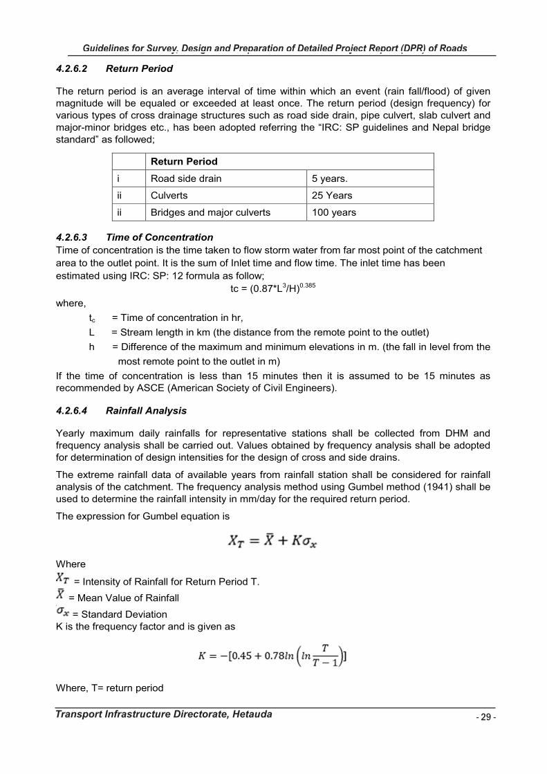
- 29 -
Guidelines for Survey, Design and Preparation of Detailed Project Report (DPR) of Roads
Transport Infrastructure Directorate, Hetauda
Guidelines for Survey Works Including Preparation of Detailed Project Report (DPR) of Roads
Transport Infrastructure Directorate, Hetauda 29
4.2.6.2 Return Period
The return period is an average interval of time within which an event (rain fall/flood) of given magnitude will be equaled or exceeded at least once. The return period (design frequency) for various types of cross drainage structures such as road side drain, pipe culvert, slab culvert and major-minor bridges etc., has been adopted referring the “IRC: SP guidelines and Nepal bridge standard” as followed;
Return Period
i Road side drain 5 years.
ii Culverts 25 Years
ii Bridges and major culverts 100 years
4.2.6.3 Time of Concentration
Time of concentration is the time taken to flow storm water from far most point of the catchment
area to the outlet point. It is the sum of Inlet time and flow time. The inlet time has been
estimated using IRC: SP: 12 formula as follow;
tc = (0.87*L3/H)0.385
where,
tc = Time of concentration in hr,
L = Stream length in km (the distance from the remote point to the outlet)
h = Difference of the maximum and minimum elevations in m. (the fall in level from the
most remote point to the outlet in m)
If the time of concentration is less than 15 minutes then it is assumed to be 15 minutes as recommended by ASCE (American Society of Civil Engineers).
4.2.6.4 Rainfall Analysis
Yearly maximum daily rainfalls for representative stations shall be collected from DHM and frequency analysis shall be carried out. Values obtained by frequency analysis shall be adopted for determination of design intensities for the design of cross and side drains.
The extreme rainfall data of available years from rainfall station shall be considered for rainfall analysis of the catchment. The frequency analysis method using Gumbel method (1941) shall be used to determine the rainfall intensity in mm/day for the required return period.
The expression for Gumbel equation is
Where
= Intensity of Rainfall for Return Period T.
= Mean Value of Rainfall
= Standard Deviation K is the frequency factor and is given as
Where, T= return period
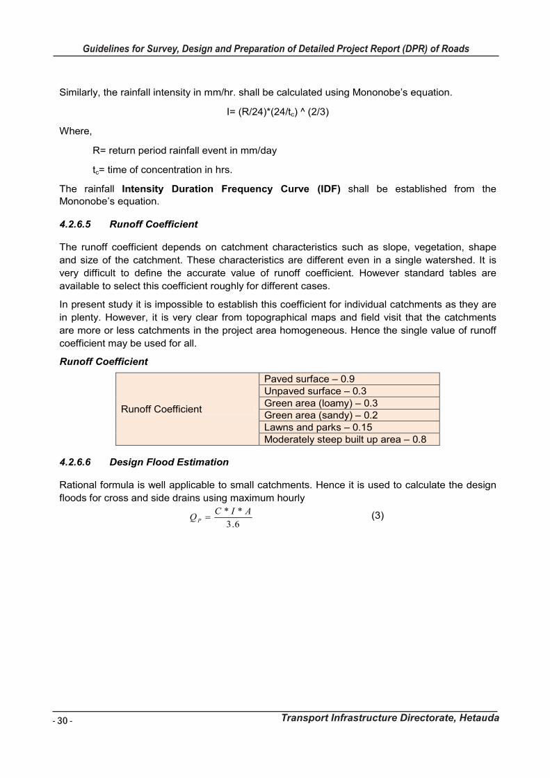
- 30 -
Guidelines for Survey, Design and Preparation of Detailed Project Report (DPR) of Roads
Transport Infrastructure Directorate, Hetauda
Guidelines for Survey Works Including Preparation of Detailed Project Report (DPR) of Roads
Transport Infrastructure Directorate, Hetauda 30
Similarly, the rainfall intensity in mm/hr. shall be calculated using Mononobe’s equation.
I= (R/24)*(24/tc) ^ (2/3)
Where,
R= return period rainfall event in mm/day
tc= time of concentration in hrs.
The rainfall Intensity Duration Frequency Curve (IDF) shall be established from the Mononobe’s equation.
4.2.6.5 Runoff Coefficient
The runoff coefficient depends on catchment characteristics such as slope, vegetation, shape
and size of the catchment. These characteristics are different even in a single watershed. It is
very difficult to define the accurate value of runoff coefficient. However standard tables are
available to select this coefficient roughly for different cases.
In present study it is impossible to establish this coefficient for individual catchments as they are
in plenty. However, it is very clear from topographical maps and field visit that the catchments
are more or less catchments in the project area homogeneous. Hence the single value of runoff
coefficient may be used for all.
Runoff Coefficient
Runoff Coefficient
Paved surface – 0.9 Unpaved surface – 0.3 Green area (loamy) – 0.3 Green area (sandy) – 0.2 Lawns and parks – 0.15 Moderately steep built up area – 0.8
4.2.6.6 Design Flood Estimation
Rational formula is well applicable to small catchments. Hence it is used to calculate the design
floods for cross and side drains using maximum hourly
6.3
** AICQP (3)
Guidelines for Survey Works Including Preparation of Detailed Project Report (DPR) of Roads
Transport Infrastructure Directorate, Hetauda 31
Where,
Qp = Maximum flood discharge in m3/s
I = Rainfall intensity within the time of concentration in mm/hr
A = Catchment area in km2
C = Dimensionless run-off coefficient
4.2.6.7 Velocities
The minimum & maximum velocities adopted for the cross drainage and side drain are based on
the “table 3.11, CPHEEO manual 2013”. The minimum and maximum velocity adopted is as
follows:
Minimum – 0.6 m/sec
Maximum – 5 m/sec
The minimum limiting velocity has been considered to prevent siltation in channel bed, whereas,
the maximum limiting velocity has been limited to prevent excessive scouring in channel wetted
surface by flow water.
4.2.6.8 Capacities of Cross Drain and Side Drains
The capacities of the cross drainage and side drains shall be calculated/checked by using the
manning’s formula as below;
� =1
� ��
���
��
Where,
A= Wetted area (m2)
P= Wetted perimeter (m)
R= Hydraulic radius (A/P) in m
S= Bed slope
N= Manning’s roughness coefficient
4.2.6.9 Cross Drains
Cross drains are mainly designed to pass the stream flows. However, in some cases the cross
drains are provided to divert the flows coming from side drains. Following steps are followed for
locating cross drains:
Identifying stream points and valley curves in topographical map
Verifying these locations during field visit and survey
Locating finally after study of designed plan and profile of the road
The design discharge for a cross drain is a high flow corresponding to the selected return period.
In order to economize on construction costs, frequency of flood is selected for return periods,
depending upon the importance of the structure. It is recommended to design the cross drains
pipe culverts for 25 years return period flood. The drain size varies based on the design
discharge. The design discharge for each drain is different. Pipe culvert shall be proposed for
- 31 -
Guidelines for Survey, Design and Preparation of Detailed Project Report (DPR) of Roads
Transport Infrastructure Directorate, Hetauda
Guidelines for Survey Works Including Preparation of Detailed Project Report (DPR) of Roads
Transport Infrastructure Directorate, Hetauda 31
Where,
Qp = Maximum flood discharge in m3/s
I = Rainfall intensity within the time of concentration in mm/hr
A = Catchment area in km2
C = Dimensionless run-off coefficient
4.2.6.7 Velocities
The minimum & maximum velocities adopted for the cross drainage and side drain are based on
the “table 3.11, CPHEEO manual 2013”. The minimum and maximum velocity adopted is as
follows:
Minimum – 0.6 m/sec
Maximum – 5 m/sec
The minimum limiting velocity has been considered to prevent siltation in channel bed, whereas,
the maximum limiting velocity has been limited to prevent excessive scouring in channel wetted
surface by flow water.
4.2.6.8 Capacities of Cross Drain and Side Drains
The capacities of the cross drainage and side drains shall be calculated/checked by using the
manning’s formula as below;
� =1
� ��
���
��
Where,
A= Wetted area (m2)
P= Wetted perimeter (m)
R= Hydraulic radius (A/P) in m
S= Bed slope
N= Manning’s roughness coefficient
4.2.6.9 Cross Drains
Cross drains are mainly designed to pass the stream flows. However, in some cases the cross
drains are provided to divert the flows coming from side drains. Following steps are followed for
locating cross drains:
Identifying stream points and valley curves in topographical map
Verifying these locations during field visit and survey
Locating finally after study of designed plan and profile of the road
The design discharge for a cross drain is a high flow corresponding to the selected return period.
In order to economize on construction costs, frequency of flood is selected for return periods,
depending upon the importance of the structure. It is recommended to design the cross drains
pipe culverts for 25 years return period flood. The drain size varies based on the design
discharge. The design discharge for each drain is different. Pipe culvert shall be proposed for
- 32 -
Guidelines for Survey, Design and Preparation of Detailed Project Report (DPR) of Roads
Transport Infrastructure Directorate, Hetauda
Guidelines for Survey Works Including Preparation of Detailed Project Report (DPR) of Roads
Transport Infrastructure Directorate, Hetauda 32
crossing the small streams as rivulet and springs do not carry debris. Pipe culverts of pipe
diameter 0.60, 0.90 and 1.20 m are considered for crossing the drains.
4.2.6.10 Side Drains
Side drains are recommended for catching the flows from road surface and upside adjoining
areas. In some stretches side drains exist but most of them occupied by new design width of the
road and new side drains are proposed along the full length of this road. The design discharge for
a side drain is a high flow corresponding to the selected return period. In order to economize on
construction costs, frequency of flood is selected for return periods, depending upon the
importance of the structure. It is recommended to design the longitudinal side drains for 5 years
return period flood.
4.2.7 Design of Traffic Safety Features and Road Markings
Traffic safety features and road furniture including traffic signals in province highways, urban
areas, if required, traffic signs, markings, overhead signboards, crash barriers, street lighting in
urban and semi-urban areas shall be designed, etc. The traffic sign and marking shall be
designed following Traffic Signs Manual published by DOR. Data on accident statistics shall be
compiled, showing accident type and frequency so that, black spots are identified along the
project road. Possible causes (such as substandard geometric features, poor intersection layout,
pavement condition, etc.) of accidents will be investigated and suitable cost-effective remedial
measures will be suggested.
The purpose of carrying out design will be to:
Minimize the risk of accidents occurring on adjacent roads as a result of operation and
maintenance of the main roads
Recognize the importance of safety in highway design needs and perception of all type of
road users, and to achieve a balanced safety solution thereto; and
Reduce the long term cost schemes, bearing in mind the overall cost-effective safe
solutions.
Minimize the risk and severity of accidents on roads
The alignment design will be verified for available sight distances as per the approved design
criteria for the Project. The provision of appropriate markings and signs will be made wherever
the existing site conditions do not permit the adherence to the sight distance requirements as per
the standard norms of DOR.
4.2.8 Design of Bioengineering Measures
Bioengineering is the use of living plants for engineering purpose. Vegetation is carefully
selected for the functions it can serve in stabilizing road side slope and for its suitability to the
site. It is usually used in combination with civil engineering structures. The basis for the design of
bio-engineering measures shall be the detailed analysis of the results of field investigation and
the information and knowledge of bio-engineering works in other road projects. The selection of
plant species for a specific site shall be done taking into consideration functional requirements,
physical and biological factors, the possibility of grazing by cattle and/or human intervention,
local availability of plants and species, etc. The main engineering functions of structures are;
Catch, Armour, Reinforce, Anchor, Support and Drain.
Guidelines for Survey Works Including Preparation of Detailed Project Report (DPR) of Roads
Transport Infrastructure Directorate, Hetauda 33
The steps for design and implementation of bioengineering techniques are:
Step 1 Make the Initial Plan and Priorities the Work
Step 2 Divide the Site into Segments
Step 3 Assess the Site
Step 4 Choose the Right Bioengineering Works
Step 5 Selected the Species to Use
Step 6 Calculate the Required Quantities and Rates
1. STEP 1: MAKE THE INITIAL PLAN AND PRIORITSE THE WORKS
The first step is making an initial plan and schedule for design and construction of bioengineering
works. The whole alignment must be inspected and make a list of sites that require treatment.
Then priorities them according to the importance of stabilization. Weighting of seriousness of the
existing or potential failure against the damage it could cause helps to priorities and schedule
works.
Expected Consequence if the Site in not Treated Priority Rating
Slope movement threatens houses Priority 1 (i.e Very High Priority
Slope movement threatens complete loss of road Priority 2
Slope movement threatens partial loss of road Priority 3
Slope movement threatens complete road blockage Priority 3
Debris may fall on top of pedestrians or vehicles and cause
injury Priority 3
Slope movement threatens loss of productive farmland Priority 4
Slope movement threatens blockage of drains Priority 4
2. STEP 2: DIVIDE THE SITE INTO SEGMENTS
It is very important to have a good knowledge of the site. A slope segment can be defined as a
length of slope with a uniform angle and homogenous material that is likely to erode or fail in
uniform manner.
The mechanical, hydrological and biological process at work in a slope are many and complex.
Nevertheless, before any remedial work can begin, it is necessary to identify the major factors
contributing to instability in order to decide on appropriate action.
The assessment and treatment of each site is based on the use of one or more techniques for
each segment. So, it is necessary to divide the slope into its component segments. Each
segment of slope must be considered a separate entity for treatment: both civil engineering and
bio-engineering techniques should be planned for each segment rather than for an entire state.
3. STEP 3 : ASSESS THE SITES
This is the most important step, and the one of which you must spend the most time. You must
make a site visit and you will need:
o Format for data collection
o Tape
o A clinometer or an Abney level
o A GPS or maps or site drawings of the road line that show the altitude
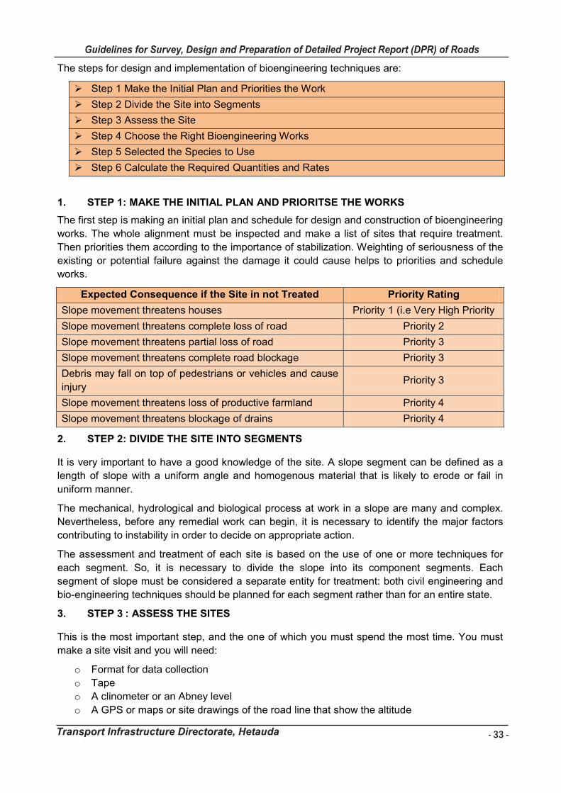
- 33 -
Guidelines for Survey, Design and Preparation of Detailed Project Report (DPR) of Roads
Transport Infrastructure Directorate, Hetauda
Guidelines for Survey Works Including Preparation of Detailed Project Report (DPR) of Roads
Transport Infrastructure Directorate, Hetauda 33
The steps for design and implementation of bioengineering techniques are:
Step 1 Make the Initial Plan and Priorities the Work
Step 2 Divide the Site into Segments
Step 3 Assess the Site
Step 4 Choose the Right Bioengineering Works
Step 5 Selected the Species to Use
Step 6 Calculate the Required Quantities and Rates
1. STEP 1: MAKE THE INITIAL PLAN AND PRIORITSE THE WORKS
The first step is making an initial plan and schedule for design and construction of bioengineering
works. The whole alignment must be inspected and make a list of sites that require treatment.
Then priorities them according to the importance of stabilization. Weighting of seriousness of the
existing or potential failure against the damage it could cause helps to priorities and schedule
works.
Expected Consequence if the Site in not Treated Priority Rating
Slope movement threatens houses Priority 1 (i.e Very High Priority
Slope movement threatens complete loss of road Priority 2
Slope movement threatens partial loss of road Priority 3
Slope movement threatens complete road blockage Priority 3
Debris may fall on top of pedestrians or vehicles and cause
injury Priority 3
Slope movement threatens loss of productive farmland Priority 4
Slope movement threatens blockage of drains Priority 4
2. STEP 2: DIVIDE THE SITE INTO SEGMENTS
It is very important to have a good knowledge of the site. A slope segment can be defined as a
length of slope with a uniform angle and homogenous material that is likely to erode or fail in
uniform manner.
The mechanical, hydrological and biological process at work in a slope are many and complex.
Nevertheless, before any remedial work can begin, it is necessary to identify the major factors
contributing to instability in order to decide on appropriate action.
The assessment and treatment of each site is based on the use of one or more techniques for
each segment. So, it is necessary to divide the slope into its component segments. Each
segment of slope must be considered a separate entity for treatment: both civil engineering and
bio-engineering techniques should be planned for each segment rather than for an entire state.
3. STEP 3 : ASSESS THE SITES
This is the most important step, and the one of which you must spend the most time. You must
make a site visit and you will need:
o Format for data collection
o Tape
o A clinometer or an Abney level
o A GPS or maps or site drawings of the road line that show the altitude
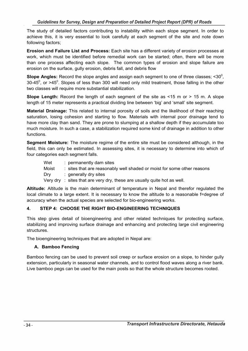
- 34 -
Guidelines for Survey, Design and Preparation of Detailed Project Report (DPR) of Roads
Transport Infrastructure Directorate, Hetauda
Guidelines for Survey Works Including Preparation of Detailed Project Report (DPR) of Roads
Transport Infrastructure Directorate, Hetauda 34
The study of detailed factors contributing to instability within each slope segment. In order to
achieve this, it is very essential to look carefully at each segment of the site and note down
following factors;
Erosion and Failure List and Process: Each site has a different variety of erosion processes at
work, which must be identified before remedial work can be started; often, there will be more
than one process affecting each slope. The common types of erosion and slope failure are
erosion on the surface, gully erosion, debris fall, and debris flow
Slope Angles: Record the slope angles and assign each segment to one of three classes; <300,
30-450, or >450. Slopes of less than 300 will need only mild treatment, those falling in the other
two classes will require more substantial stabilization.
Slope Length: Record the length of each segment of the site as <15 m or > 15 m. A slope
length of 15 meter represents a practical dividing line between ‘big’ and ‘small’ site segment.
Material Drainage: This related to internal porosity of soils and the likelihood of their reaching
saturation, losing cohesion and starting to flow. Materials with internal poor drainage tend to
have more clay than sand. They are prone to slumping at a shallow depth if they accumulate too
much moisture. In such a case, a stabilization required some kind of drainage in addition to other
functions.
Segment Moisture: The moisture regime of the entire site must be considered although, in the
field, this can only be estimated. In assessing sites, it is necessary to determine into which of
four categories each segment falls.
Wet : permanently dam sites
Moist : sites that are reasonably well shaded or moist for some other reasons
Dry : generally dry sites
Very dry : sites that are very dry, these are usually quite hot as well.
Altitude: Altitude is the main determinant of temperature in Nepal and therefor regulated the
local climate to a large extent. It is necessary to know the altitude to a reasonable f=degree of
accuracy when the actual species are selected for bio-engineering works.
4. STEP 4: CHOOSE THE RIGHT BIO-ENGINEERING TECHNIQUES
This step gives detail of bioengineering and other related techniques for protecting surface,
stabilizing and improving surface drainage and enhancing and protecting large civil engineering
structures.
The bioengineering techniques that are adopted in Nepal are:
A. Bamboo Fencing
Bamboo fencing can be used to prevent soil creep or surface erosion on a slope, to hinder gully
extension, particularly in seasonal water channels, and to control flood waves along a river bank.
Live bamboo pegs can be used for the main posts so that the whole structure becomes rooted.
Guidelines for Survey Works Including Preparation of Detailed Project Report (DPR) of Roads
Transport Infrastructure Directorate, Hetauda 35
The growing bamboo can be further interleaved between the posts (as in a wattle fence) to
increase the strength of the fence. Shrubs and grasses are planted on the upper side of the
fence to hold small soil particles. The main purpose is to trap loose sediments on the slope, to
improve the conditions for growing vegetation, and to reduce the surface runoff rate.
Bamboos fencing on a slope – the posts (pegs) are live bamboo that will sprout to provide foliage
(left); detail showing live bamboo peg with sprouting leaves (right).
Materials
Live bamboo pegs or strong bamboo poles about 1.5 m long and 10–15 cm in diameter
Digging tools
Seeds or plants of grasses or shrubs
Installation
Starting from the base of the slope, mark the line for the fence with string.
Dig a long pit about 45–50 cm deep along the contour of the slope for each line of
fencing.
Insert a row of bamboo poles or pegs 40 cm apart into the pit and back fill the pit to
stabilize the poles.
Weave split bamboo or branches in and out between the poles to form a semi-solid face.
Plant small grasses and/or shrubs along the upper side of the fence.
Regular maintenance is important to ensure longevity of the fence. Any broken sections
should be replaced immediately.
B. Brush Layering
In brush layering, live cut branches are interspersed between layers of soil to stabilize a slope
against shallow sliding or erosion. Fresh green cuttings are layered in lines across the slope. As
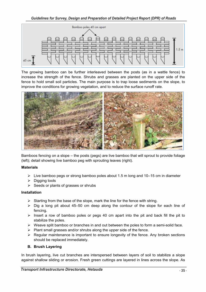
- 35 -
Guidelines for Survey, Design and Preparation of Detailed Project Report (DPR) of Roads
Transport Infrastructure Directorate, Hetauda
Guidelines for Survey Works Including Preparation of Detailed Project Report (DPR) of Roads
Transport Infrastructure Directorate, Hetauda 35
The growing bamboo can be further interleaved between the posts (as in a wattle fence) to
increase the strength of the fence. Shrubs and grasses are planted on the upper side of the
fence to hold small soil particles. The main purpose is to trap loose sediments on the slope, to
improve the conditions for growing vegetation, and to reduce the surface runoff rate.
Bamboos fencing on a slope – the posts (pegs) are live bamboo that will sprout to provide foliage
(left); detail showing live bamboo peg with sprouting leaves (right).
Materials
Live bamboo pegs or strong bamboo poles about 1.5 m long and 10–15 cm in diameter
Digging tools
Seeds or plants of grasses or shrubs
Installation
Starting from the base of the slope, mark the line for the fence with string.
Dig a long pit about 45–50 cm deep along the contour of the slope for each line of
fencing.
Insert a row of bamboo poles or pegs 40 cm apart into the pit and back fill the pit to
stabilize the poles.
Weave split bamboo or branches in and out between the poles to form a semi-solid face.
Plant small grasses and/or shrubs along the upper side of the fence.
Regular maintenance is important to ensure longevity of the fence. Any broken sections
should be replaced immediately.
B. Brush Layering
In brush layering, live cut branches are interspersed between layers of soil to stabilize a slope
against shallow sliding or erosion. Fresh green cuttings are layered in lines across the slope. As
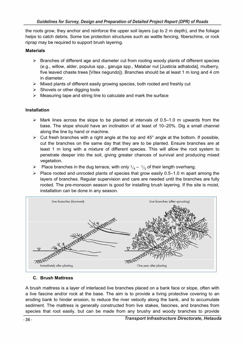
- 36 -
Guidelines for Survey, Design and Preparation of Detailed Project Report (DPR) of Roads
Transport Infrastructure Directorate, Hetauda
Guidelines for Survey Works Including Preparation of Detailed Project Report (DPR) of Roads
Transport Infrastructure Directorate, Hetauda 36
the roots grow, they anchor and reinforce the upper soil layers (up to 2 m depth), and the foliage
helps to catch debris. Some toe protection structures such as wattle fencing, fiberschine, or rock
riprap may be required to support brush layering.
Materials
Branches of different age and diameter cut from rooting woody plants of different species
(e.g., willow, alder, populus spp., garuga spp., Malabar nut [Justicia adhatoda], mulberry,
five leaved chaste trees [Vitex negundo]). Branches should be at least 1 m long and 4 cm
in diameter.
Mixed plants of different easily growing species, both rooted and freshly cut
Shovels or other digging tools
Measuring tape and string line to calculate and mark the surface
Installation
Mark lines across the slope to be planted at intervals of 0.5–1.0 m upwards from the
base. The slope should have an inclination of at least of 10–20%. Dig a small channel
along the line by hand or machine.
Cut fresh branches with a right angle at the top and 45° angle at the bottom. If possible,
cut the branches on the same day that they are to be planted. Ensure branches are at
least 1 m long with a mixture of different species. This will allow the root system to
penetrate deeper into the soil, giving greater chances of survival and producing mixed
vegetation.
Place branches in the dug terrace, with only 1 4� – 1 5� of their length overhang.
Place rooted and unrooted plants of species that grow easily 0.5–1.0 m apart among the
layers of branches. Regular supervision and care are needed until the branches are fully
rooted. The pre-monsoon season is good for installing brush layering. If the site is moist,
installation can be done in any season.
C. Brush Mattress
A brush mattress is a layer of interlaced live branches placed on a bank face or slope, often with
a live fascine and/or rock at the base. The aim is to provide a living protective covering to an
eroding bank to hinder erosion, to reduce the river velocity along the bank, and to accumulate
sediment. The mattress is generally constructed from live stakes, fascines, and branches from
species that root easily, but can be made from any brushy and woody branches to provide
Guidelines for Survey Works Including Preparation of Detailed Project Report (DPR) of Roads
Transport Infrastructure Directorate, Hetauda 37
immediate and effective protection. A layer of biodegradable material such as loosely woven jute
can be placed under the mat on steep slopes to increase stability if the soil is very loose. The
mattress that is formed protects the surface of the bank until the branches can root and native
vegetation becomes established.
Materials
Live branches 2–3 m long and approximately 2.5 cm in diameter Fascine bundles Live and/or dead wooden stakes Digging tools (shovel)
Installation
Prepare the site by clearing away large debris and other materials If desired, cover the slope with a layer of biodegradable material, e.g., jute netting, to
provide extra stability Dig a horizontal trench 20–30 cm deep at the toe of the bank or slope. Lie the cuttings flat on the graded slope in an overlapping crisscross pattern with the root
ends pushed into the soil in the trench to below the water level and the growing tips placed at a slight angle in the direction of the stream flow (if on a stream bank) or parallel to the slope.
Branches should be placed at a density of approximately 4 branches every 15 cm. Pound wooden stakes between the branches into the soil to half their length and about 1
m apart. Wrap wire around the stakes and over the branches as tightly as possible. Pound the wooden stakes further in to tighten the wire and press the branches down onto
the slope. Push live stakes into the ground between the wooden stakes. Place bundles of fascines along the trench at the base of the slope over the bottom of the
branches and cover with soil, leaving the tops slightly exposed. Fill any voids around and in between the branches with loose soil (from the trench) to
promote rooting. Periodic maintenance is required to ensure the mattress is securely tied to the slope.
D. Fiberschine
Fiberschine is a roll of material made from coconut fiber used to form a toe protection structure on a slope and to trap any sediment derived from erosion. The most common use is to stabilize the base of a stream bank or shoreline, but it can also be used in slope stabilization to support other measures such as brush layering. Live cuttings from herbaceous plants are planted together with the fiberschine; by the time the fiberschine decomposes, the vegetation will have
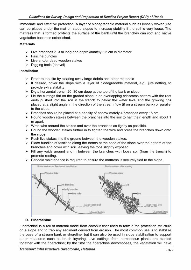
- 37 -
Guidelines for Survey, Design and Preparation of Detailed Project Report (DPR) of Roads
Transport Infrastructure Directorate, Hetauda
Guidelines for Survey Works Including Preparation of Detailed Project Report (DPR) of Roads
Transport Infrastructure Directorate, Hetauda 37
immediate and effective protection. A layer of biodegradable material such as loosely woven jute
can be placed under the mat on steep slopes to increase stability if the soil is very loose. The
mattress that is formed protects the surface of the bank until the branches can root and native
vegetation becomes established.
Materials
Live branches 2–3 m long and approximately 2.5 cm in diameter Fascine bundles Live and/or dead wooden stakes Digging tools (shovel)
Installation
Prepare the site by clearing away large debris and other materials If desired, cover the slope with a layer of biodegradable material, e.g., jute netting, to
provide extra stability Dig a horizontal trench 20–30 cm deep at the toe of the bank or slope. Lie the cuttings flat on the graded slope in an overlapping crisscross pattern with the root
ends pushed into the soil in the trench to below the water level and the growing tips placed at a slight angle in the direction of the stream flow (if on a stream bank) or parallel to the slope.
Branches should be placed at a density of approximately 4 branches every 15 cm. Pound wooden stakes between the branches into the soil to half their length and about 1
m apart. Wrap wire around the stakes and over the branches as tightly as possible. Pound the wooden stakes further in to tighten the wire and press the branches down onto
the slope. Push live stakes into the ground between the wooden stakes. Place bundles of fascines along the trench at the base of the slope over the bottom of the
branches and cover with soil, leaving the tops slightly exposed. Fill any voids around and in between the branches with loose soil (from the trench) to
promote rooting. Periodic maintenance is required to ensure the mattress is securely tied to the slope.
D. Fiberschine
Fiberschine is a roll of material made from coconut fiber used to form a toe protection structure on a slope and to trap any sediment derived from erosion. The most common use is to stabilize the base of a stream bank or shoreline, but it can also be used in slope stabilization to support other measures such as brush layering. Live cuttings from herbaceous plants are planted together with the fiberschine; by the time the fiberschine decomposes, the vegetation will have
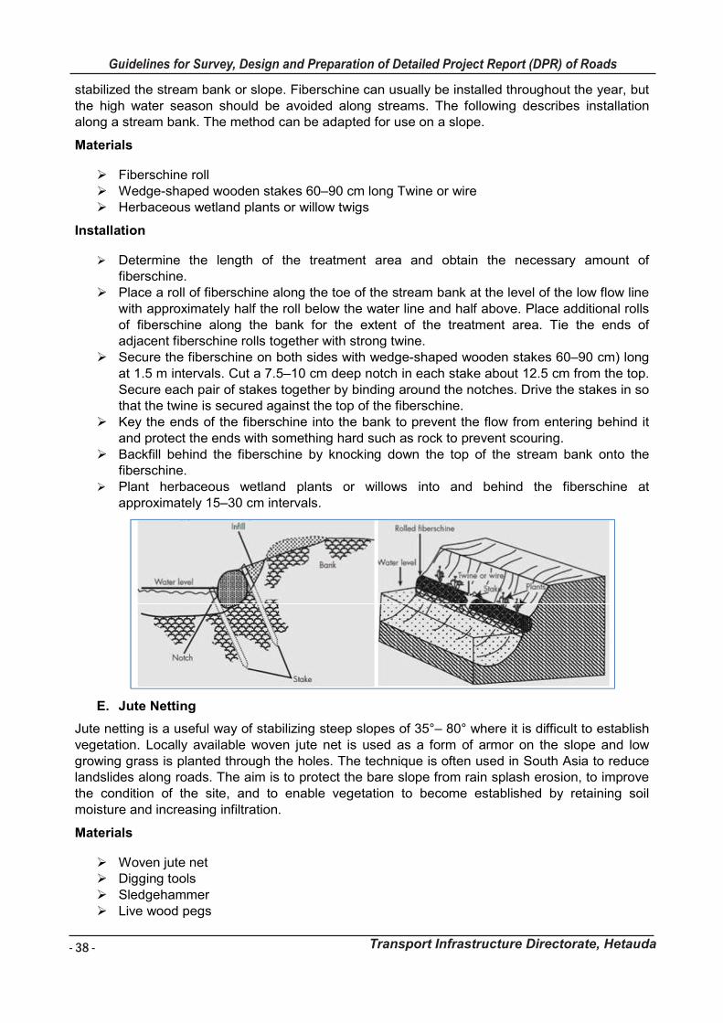
- 38 -
Guidelines for Survey, Design and Preparation of Detailed Project Report (DPR) of Roads
Transport Infrastructure Directorate, Hetauda
Guidelines for Survey Works Including Preparation of Detailed Project Report (DPR) of Roads
Transport Infrastructure Directorate, Hetauda 38
stabilized the stream bank or slope. Fiberschine can usually be installed throughout the year, but the high water season should be avoided along streams. The following describes installation along a stream bank. The method can be adapted for use on a slope.
Materials
Fiberschine roll Wedge-shaped wooden stakes 60–90 cm long Twine or wire Herbaceous wetland plants or willow twigs
Installation
Determine the length of the treatment area and obtain the necessary amount of fiberschine.
Place a roll of fiberschine along the toe of the stream bank at the level of the low flow line with approximately half the roll below the water line and half above. Place additional rolls of fiberschine along the bank for the extent of the treatment area. Tie the ends of adjacent fiberschine rolls together with strong twine.
Secure the fiberschine on both sides with wedge-shaped wooden stakes 60–90 cm) long at 1.5 m intervals. Cut a 7.5–10 cm deep notch in each stake about 12.5 cm from the top. Secure each pair of stakes together by binding around the notches. Drive the stakes in so that the twine is secured against the top of the fiberschine.
Key the ends of the fiberschine into the bank to prevent the flow from entering behind it and protect the ends with something hard such as rock to prevent scouring.
Backfill behind the fiberschine by knocking down the top of the stream bank onto the fiberschine.
Plant herbaceous wetland plants or willows into and behind the fiberschine at approximately 15–30 cm intervals.
E. Jute Netting
Jute netting is a useful way of stabilizing steep slopes of 35°– 80° where it is difficult to establish vegetation. Locally available woven jute net is used as a form of armor on the slope and low growing grass is planted through the holes. The technique is often used in South Asia to reduce landslides along roads. The aim is to protect the bare slope from rain splash erosion, to improve the condition of the site, and to enable vegetation to become established by retaining soil moisture and increasing infiltration.
Materials
Woven jute net Digging tools Sledgehammer Live wood pegs
Guidelines for Survey Works Including Preparation of Detailed Project Report (DPR) of Roads
Transport Infrastructure Directorate, Hetauda 39
Grass seed or small-rooted tufts of grass
Installation
Trim the slope so that it is even and clear away any hanging masses or depressions. Spread fertile soil on the bare slope. Mulch with straw or other soft vegetation. Start laying netting along a line above the slope to be covered, secure by hammering
wooden pegs through the net at 0.3 m intervals. Unroll the net down the slope and fix by hammering live wood pegs through it at intervals
of 0.5–1.0 m. Continue until the whole slope is covered by netting. Sow grass seed or plant small grass clumps through the netting diagonally at a spacing of 10cm by 10cm over the entire area.
Regular supervision and care are needed until the grass is fully grown
F. Live Crib Wall
A crib wall is a box structure made of interlocking struts (either logs or precast structures made of concrete, recycled polymers, or other material) and back-filled with boulders, soil, or similar. They are mainly used to stabilize steep banks and protect them against undercutting, for example a stream bank or the side of a cutting made for a road, and are also a useful method for stabilizing the toe of a slope. However, they are only effective where the volume of soil to be stabilized is relatively small. In a live crib wall, live branches and well-rooted plants are placed between interlocking logs where they can grow and develop a root network that further strengthens the wall. If needed, the anchor and cross logs can be held together with nails or bolts. Vegetated crib walls provide immediate protection, and their effectiveness increases over time as the vegetation grows. Once the plants become established, the vegetation gradually takes over the structural functions of the wooden supports. Crib walls should be installed at an angle of 10–15° towards the slope to increase stability. Green willow branches can be used to ensure a quick outcome.
Materials
Live branches 1–6 cm in diameter and long enough to reach from the front to the back of the structure with an overhang at both ends.
Logs, timber, or bamboo 1–2 m long
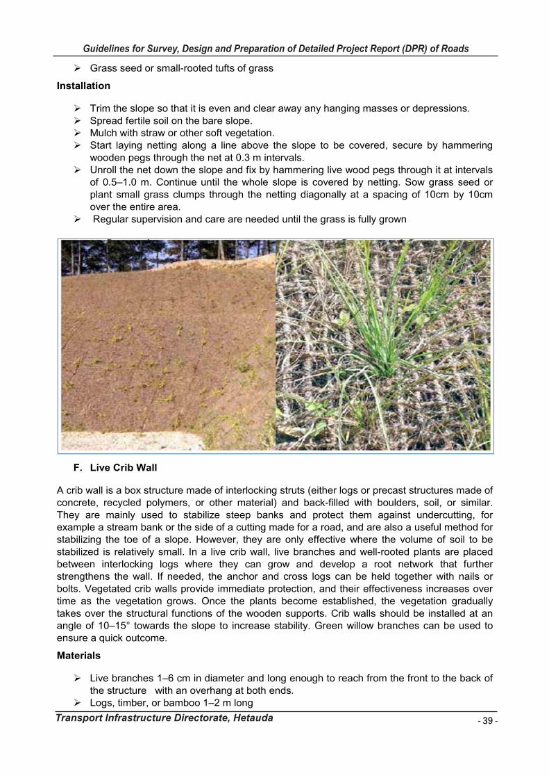
- 39 -
Guidelines for Survey, Design and Preparation of Detailed Project Report (DPR) of Roads
Transport Infrastructure Directorate, Hetauda
Guidelines for Survey Works Including Preparation of Detailed Project Report (DPR) of Roads
Transport Infrastructure Directorate, Hetauda 39
Grass seed or small-rooted tufts of grass
Installation
Trim the slope so that it is even and clear away any hanging masses or depressions. Spread fertile soil on the bare slope. Mulch with straw or other soft vegetation. Start laying netting along a line above the slope to be covered, secure by hammering
wooden pegs through the net at 0.3 m intervals. Unroll the net down the slope and fix by hammering live wood pegs through it at intervals
of 0.5–1.0 m. Continue until the whole slope is covered by netting. Sow grass seed or plant small grass clumps through the netting diagonally at a spacing of 10cm by 10cm over the entire area.
Regular supervision and care are needed until the grass is fully grown
F. Live Crib Wall
A crib wall is a box structure made of interlocking struts (either logs or precast structures made of concrete, recycled polymers, or other material) and back-filled with boulders, soil, or similar. They are mainly used to stabilize steep banks and protect them against undercutting, for example a stream bank or the side of a cutting made for a road, and are also a useful method for stabilizing the toe of a slope. However, they are only effective where the volume of soil to be stabilized is relatively small. In a live crib wall, live branches and well-rooted plants are placed between interlocking logs where they can grow and develop a root network that further strengthens the wall. If needed, the anchor and cross logs can be held together with nails or bolts. Vegetated crib walls provide immediate protection, and their effectiveness increases over time as the vegetation grows. Once the plants become established, the vegetation gradually takes over the structural functions of the wooden supports. Crib walls should be installed at an angle of 10–15° towards the slope to increase stability. Green willow branches can be used to ensure a quick outcome.
Materials
Live branches 1–6 cm in diameter and long enough to reach from the front to the back of the structure with an overhang at both ends.
Logs, timber, or bamboo 1–2 m long
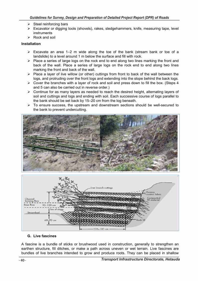
- 40 -
Guidelines for Survey, Design and Preparation of Detailed Project Report (DPR) of Roads
Transport Infrastructure Directorate, Hetauda
Guidelines for Survey Works Including Preparation of Detailed Project Report (DPR) of Roads
Transport Infrastructure Directorate, Hetauda 40
Steel reinforcing bars Excavator or digging tools (shovels), rakes, sledgehammers, knife, measuring tape, level
instruments Rock and soil
Installation
Excavate an area 1–2 m wide along the toe of the bank (stream bank or toe of a landslide) to a level around 1 m below the surface and fill with rock.
Place a series of large logs on the rock end to end along two lines marking the front and back of the wall. Place a series of large logs on the rock end to end along two lines marking the front and back of the wall.
Place a layer of live willow (or other) cuttings from front to back of the wall between the logs, and protruding over the front logs and extending into the slope behind the back logs.
Cover the branches with a layer of rock and soil and press down to fill the box. (Steps 4 and 5 can also be carried out in reverse order.)
Continue for as many layers as needed to reach the desired height, alternating layers of soil and cuttings and logs and ending with soil. Each successive course of logs parallel to the bank should be set back by 15–20 cm from the log beneath.
To ensure success, the upstream and downstream sections should be well-secured to the bank to prevent undercutting.
G. Live fascines
A fascine is a bundle of sticks or brushwood used in construction, generally to strengthen an earthen structure, fill ditches, or make a path across uneven or wet terrain. Live fascines are bundles of live branches intended to grow and produce roots. They can be placed in shallow
Guidelines for Survey Works Including Preparation of Detailed Project Report (DPR) of Roads
Transport Infrastructure Directorate, Hetauda 41
trenches on a stream bank to reduce erosion across the bank and increase soil stability. The rooted branches protect the toe of the stream bank from erosion and improve infiltration. Properly placed, the bundles can also trap debris and sediment. Live fascines can also be used to reinforce slopes and increase drainage and infiltration. They are installed perpendicular to the slope in dug trenches or in existing gullies and rills. The optimum spacing depends on the steepness of the slope, usually 4 m intervals for slopes of less than 30° and 2 m intervals for slopes of 30–45°. They are most effective on soft cut slopes or slopes with consolidated debris. Draining effects can be seen as soon as the fascines are established.
Materials
Live branches of rooting plants of different species 3–5 cm in diameter and 50–100 cm or more long.
Live wooden stakes ready to sprout 3–6 cm in diameter and 50–100 cm long. Dead wooden stakes 3–6 cm in diameter and 50–75 cm long Digging tools Jute or coir string or wire to bind the fascines.
Installation
Prepare the site by clearing away loose material and protrusions and firmly infill any depressions.
Mark the lines along which fascines are to be installed. The lines should follow the contours, or be at a desired angle or along rills and at intervals of 2–4 m up the slope (2 m for slopes of 30°–45°; 4 m for slopes of less than 30°).
Excavate trenches approximately 10 cm deep and 20–40 cm wide along the marked lines starting from the bottom of the slope and working upwards.
Bind 4–8 live branches into bundles (fascines) using string or wire. Place the fascines lengthwise in the trenches. Drive alive or dead stakes directly through the fascines every meter or so flush with the
top of the fascines, and where the bundles connect. Drive live stakes into the soil immediately below the fascines, protruding about 7 cm
above the fascine. Backfill the trench with moist soil to the side of the fascine, but allow the top of the fascine to show. Riprap can be used to stabilize the toe of the slope and prevent scouring.
Backfill the trench with moist soil to the side of the fascine, but allow the top of the fascine to show.
Riprap can be used to stabilize the toe of the slope and prevent scouring.
H. Palisades
A palisade is a fence or wall made from wooden stakes or tree trunks. Palisades were used historically as a defensive structure. In slope protection, palisades are barriers made from live wood cuttings or bamboo installed across a slope following the contour in order to trap debris moving down the slope, to armour and reinforce the slope, and to increase the infiltration rate. Palisades are used to prevent the extension of deep, narrow gullies and the erosion of V-shaped rills by forming a strong barrier which stabilizes the gully floor and traps material moving downwards (Lammeranner et al. 2005). They are also effective on steep landslide or debris slopes. Palisades can be used on a wide range of sites with slopes of up to about 60°.
Materials
Stakes made from cuttings of rooting plants of different species 3–5 cm in diameter and 30–50 cm long
Cross beam
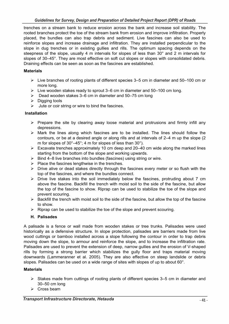
- 41 -
Guidelines for Survey, Design and Preparation of Detailed Project Report (DPR) of Roads
Transport Infrastructure Directorate, Hetauda
Guidelines for Survey Works Including Preparation of Detailed Project Report (DPR) of Roads
Transport Infrastructure Directorate, Hetauda 41
trenches on a stream bank to reduce erosion across the bank and increase soil stability. The rooted branches protect the toe of the stream bank from erosion and improve infiltration. Properly placed, the bundles can also trap debris and sediment. Live fascines can also be used to reinforce slopes and increase drainage and infiltration. They are installed perpendicular to the slope in dug trenches or in existing gullies and rills. The optimum spacing depends on the steepness of the slope, usually 4 m intervals for slopes of less than 30° and 2 m intervals for slopes of 30–45°. They are most effective on soft cut slopes or slopes with consolidated debris. Draining effects can be seen as soon as the fascines are established.
Materials
Live branches of rooting plants of different species 3–5 cm in diameter and 50–100 cm or more long.
Live wooden stakes ready to sprout 3–6 cm in diameter and 50–100 cm long. Dead wooden stakes 3–6 cm in diameter and 50–75 cm long Digging tools Jute or coir string or wire to bind the fascines.
Installation
Prepare the site by clearing away loose material and protrusions and firmly infill any depressions.
Mark the lines along which fascines are to be installed. The lines should follow the contours, or be at a desired angle or along rills and at intervals of 2–4 m up the slope (2 m for slopes of 30°–45°; 4 m for slopes of less than 30°).
Excavate trenches approximately 10 cm deep and 20–40 cm wide along the marked lines starting from the bottom of the slope and working upwards.
Bind 4–8 live branches into bundles (fascines) using string or wire. Place the fascines lengthwise in the trenches. Drive alive or dead stakes directly through the fascines every meter or so flush with the
top of the fascines, and where the bundles connect. Drive live stakes into the soil immediately below the fascines, protruding about 7 cm
above the fascine. Backfill the trench with moist soil to the side of the fascine, but allow the top of the fascine to show. Riprap can be used to stabilize the toe of the slope and prevent scouring.
Backfill the trench with moist soil to the side of the fascine, but allow the top of the fascine to show.
Riprap can be used to stabilize the toe of the slope and prevent scouring.
H. Palisades
A palisade is a fence or wall made from wooden stakes or tree trunks. Palisades were used historically as a defensive structure. In slope protection, palisades are barriers made from live wood cuttings or bamboo installed across a slope following the contour in order to trap debris moving down the slope, to armour and reinforce the slope, and to increase the infiltration rate. Palisades are used to prevent the extension of deep, narrow gullies and the erosion of V-shaped rills by forming a strong barrier which stabilizes the gully floor and traps material moving downwards (Lammeranner et al. 2005). They are also effective on steep landslide or debris slopes. Palisades can be used on a wide range of sites with slopes of up to about 60°.
Materials
Stakes made from cuttings of rooting plants of different species 3–5 cm in diameter and 30–50 cm long
Cross beam
- 42 -
Guidelines for Survey, Design and Preparation of Detailed Project Report (DPR) of Roads
Transport Infrastructure Directorate, Hetauda
Guidelines for Survey Works Including Preparation of Detailed Project Report (DPR) of Roads
Transport Infrastructure Directorate, Hetauda 42
Gabion wire Digging tools such as crowbars and shovels
Installation
Installation should start from the top of the slope and work down Clean or trim the site, remove unnecessary irregularities of slope and loose material. Mark the places to be planted. Palisades should be spaced at intervals of about 2 m
down a slope of less than 30° and 1 m down a slope of 30-600. Make holes with the help of a pointed bar or crowbar for planting the cuttings. Trim the top of the cuttings at a right angle to the stem and the bottom at an angle of 45°. Place at least two-thirds of the length of the cutting into the hole and pack the soil around
it. Tie the stakes with pieces of gabion wire to a cross beam which is anchored in the sides
of the gully and protected by pegs at either end. On steep gullies and rills, support the palisade by placing a layer of stone and soil in front
of and below the structure. Regular inspection is necessary throughout the year. Broken stakes should be repaired
and strengthened to encourage vegetation to develop. Thinning might be required after a few years.

- 43 -
Guidelines for Survey, Design and Preparation of Detailed Project Report (DPR) of Roads
Transport Infrastructure Directorate, Hetauda
Gu
idelin
es f
or
Su
rvey
Wo
rks In
clu
din
g P
rep
ara
tio
n o
f D
eta
iled
Pro
ject
Rep
ort
(D
PR
) o
f R
oad
s
Tra
nsp
ort
In
frastr
uctu
re D
irecto
rate
4
3
Ma
jor
Pro
ble
ms a
nd
th
eir
Rem
ed
ies
Ph
en
om
en
on
E
rosio
n P
rob
lem
an
d C
on
dit
ion
S
uit
ab
le B
ioe
ng
ine
eri
ng
Te
ch
niq
ue
s
La
nd
sli
de
Dee
p-r
oo
ted la
nd
slid
e (
>3
m d
epth
o
S
mo
oth
ing
to
a s
uita
ble
slo
pe
gra
die
nt
o
Div
ers
ion
ca
na
ls,
ch
ann
el
linin
g,
ca
tch
dra
ins,
wa
terw
ays
S
ton
e p
itch
ing
an
d p
lantin
g o
f tr
ee
s, s
hru
bs a
nd
gra
ss s
lip
Bam
bo
o fe
ncin
g w
ith
liv
e p
ole
s,
pla
ntin
g a
nd
se
edin
g g
rass
o
T
err
acin
g a
nd
p
lan
ting
w
ith
ba
mb
oo
, tr
ee
s,
shru
bs,
gra
ss
Liv
e p
eg
fe
nce
, w
ild s
hru
bs,
live
ch
eck
dam
s
o
Con
tou
r st
rips
pla
nte
d
with
g
rass,
sh
rub
s,
an
d
peg
s F
ascin
es,
bru
sh
la
yerin
g, a
nd
pa
lisa
de
s
o
Pla
ntin
g b
am
bo
o w
ith
or
with
ou
t a s
tru
ctu
re
o
Che
ck
da
ms
pla
nte
d
with
d
ee
p-r
oote
d
spe
cie
s
(e.g
.,
ba
mb
oo
, tr
ee
s)
Slu
mp
ing
Pla
na
r S
lidin
g
She
ar
Fa
ilure
Cut
an
d
fill
are
a
at
de
ep
an
d
sh
allo
w
roote
d
lan
dslid
e (
< 3
m d
ep
th)
Bare
an
d S
tee
p s
lop
e o
r n
ew
ly e
xpo
se
d s
urf
ace
Cra
ckin
g Z
on
e
o
Bam
bo
o f
en
cin
g a
bo
ve z
on
e;
zon
e c
ove
red
with
po
lyth
en
e
sh
ee
t
o
Catc
h d
rain
with
ve
ge
tatio
n
o
Fa
scin
es,
bru
sh
la
yerin
g, a
nd
pa
lisa
de
s
Hea
d s
ca
rp o
f la
nd
slid
e
or
slo
pe
fa
ilure
o
Slo
pe
e
xca
vate
d
to
an
ap
pro
priate
g
rad
ien
t an
d
rou
nd
ed
(wh
en
hig
h a
nd s
tee
p)
an
d
o
pla
nte
d
with
d
ee
p-r
oote
d
pla
nts
(e
.g.,
b
am
bo
o,
tre
es)
Bam
bo
o
fen
cin
g,
pla
ntin
g
gra
ss,
se
ed
ing
, a
nd
m
ulc
hin
g
Fa
scin
es,
bru
sh
la
yerin
g, a
nd
pa
lisa
de
s
o
Ju
te n
ett
ing
or
stra
w m
at
co
verin
g s
oil,
se
ed
s,
an
d c
om
post
mix
ture
; tu
rfin
g
o
Sto
ne
p
itch
ing
; p
lan
ting
of
tre
es,
sh
rub
s,
an
d
gra
ss
slip
P
lan
tin
g g
rass
slip
an
d s
ee
din
g g
rass
Deb
ris
flo
w
Sed
ime
nt
pro
du
ctio
n z
on
e
o
As f
or
lan
dslid
es
Sed
ime
nt
tra
nsp
ort
atio
n z
on
e
o
Serie
s o
f g
ab
ion
ch
eck
da
ms,
reta
inin
g w
all,
an
d s
ide
wa
ll p
lan
ted
with
de
ep-r
oote
d
o
sp
ecie
s (
e.g
., b
am
bo
o,
tree
s)
o
B
am
bo
o fe
ncin
g; g
rass
pla
ntin
g, se
ed
ing
, a
nd
mu
lch
ing
Sed
ime
nt
de
positi
on
zo
ne
o
Div
ers
ion c
an
al,
ch
an
ne
l lin
ing
, re
tain
ing
wa
ll, a
nd
sid
e w
all
pla
nte
d w
ith
tre
es,
sh
rubs,
o
an
d g
rasses
o
Pla
nta
tio
n o
f d
ee
p-r
oo
ted
sp
ecie
s (
e.g
., b
am
bo
o, tr
ee
s)
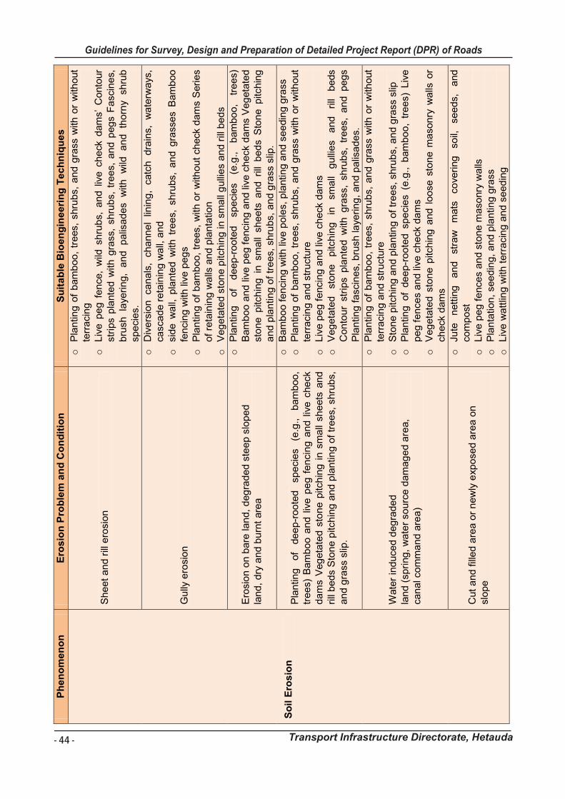
- 44 -
Guidelines for Survey, Design and Preparation of Detailed Project Report (DPR) of Roads
Transport Infrastructure Directorate, Hetauda
Gu
idelin
es f
or
Su
rvey
Wo
rks In
clu
din
g P
rep
ara
tio
n o
f D
eta
iled
Pro
ject
Rep
ort
(D
PR
) o
f R
oad
s
Tra
nsp
ort
In
frastr
uctu
re D
irecto
rate
4
4
Ph
en
om
en
on
E
rosio
n P
rob
lem
an
d C
on
dit
ion
S
uit
ab
le B
ioe
ng
ine
eri
ng
Te
ch
niq
ue
s
So
il E
ros
ion
She
et
an
d r
ill e
rosio
n
o
Pla
ntin
g o
f b
am
bo
o,
tre
es,
shru
bs,
an
d g
rass w
ith
or
with
out
terr
acin
g
o
Liv
e p
eg
fe
nce,
wild
sh
rub
s,
an
d l
ive
ch
eck
dam
s’
Conto
ur
str
ips p
lante
d w
ith
gra
ss,
sh
rub
s,
tre
es,
an
d p
eg
s F
ascin
es,
b
rush
la
yerin
g,
an
d
pa
lisa
de
s
with
w
ild
an
d
tho
rny
sh
rub
sp
ecie
s.
Gu
lly e
rosio
n
o
Div
ers
ion
ca
na
ls,
ch
ann
el
linin
g,
catc
h
dra
ins,
wa
terw
ays
, ca
sca
de r
eta
inin
g w
all,
an
d
o
sid
e w
all,
pla
nte
d w
ith
tre
es,
sh
rubs,
an
d g
rasse
s B
am
boo
fen
cin
g w
ith
liv
e p
eg
s
o
Pla
ntin
g o
f b
am
bo
o,
tre
es,
with
or
with
ou
t ch
eck
da
ms S
erie
s of
reta
inin
g w
alls
an
d p
lan
tatio
n
o
Veg
eta
ted s
ton
e p
itch
ing
in
sm
all
gu
llie
s a
nd r
ill b
ed
s
Ero
sio
n o
n b
are
lan
d,
deg
rad
ed s
tee
p s
lop
ed
la
nd
, d
ry a
nd
bu
rnt
are
a
o
Pla
ntin
g
of
de
ep-r
oo
ted
sp
ecie
s
(e.g
.,
bam
bo
o,
tre
es)
B
am
bo
o a
nd
liv
e p
eg
fe
ncin
g a
nd liv
e c
he
ck d
am
s V
eg
eta
ted
sto
ne p
itch
ing
in s
ma
ll sh
ee
ts a
nd r
ill b
ed
s S
ton
e p
itch
ing
a
nd
pla
ntin
g o
f tr
ee
s, s
hru
bs,
an
d g
rass s
lip.
Pla
ntin
g
of
de
ep-r
oo
ted
sp
ecie
s
(e.g
.,
ba
mbo
o,
tre
es)
Bam
bo
o a
nd l
ive
pe
g f
en
cin
g a
nd l
ive
che
ck
da
ms V
eg
eta
ted s
ton
e p
itch
ing
in s
ma
ll sh
eets
an
d
rill
be
ds S
ton
e p
itch
ing
an
d p
lan
tin
g o
f tr
ee
s, s
hru
bs,
an
d g
rass s
lip.
o
Bam
bo
o fe
ncin
g w
ith
liv
e p
ole
s,
pla
ntin
g a
nd
se
edin
g g
rass
o
P
lan
tin
g o
f b
am
bo
o,
tre
es,
shru
bs,
an
d g
rass w
ith
or
with
out
terr
acin
g a
nd
str
uctu
re
o
Liv
e p
eg
fe
ncin
g a
nd
liv
e c
he
ck d
am
s
o
Veg
eta
ted
sto
ne
p
itch
ing
in
sm
all
gu
llie
s
and
rill
beds
Con
tou
r st
rips p
lan
ted
with
gra
ss,
sh
rub
s, t
rees,
an
d p
eg
s P
lan
tin
g f
ascin
es, b
rush
laye
rin
g,
an
d p
alis
ad
es.
Wate
r in
du
ce
d d
eg
rad
ed
lan
d (
sp
ring
, w
ate
r so
urc
e d
am
ag
ed a
rea,
ca
na
l co
mm
an
d a
rea
)
o
Pla
ntin
g o
f b
am
bo
o,
tre
es,
shru
bs,
an
d g
rass w
ith
or
with
out
terr
acin
g a
nd
str
uctu
re
o
Sto
ne
pitch
ing
an
d p
lantin
g o
f tr
ee
s, shru
bs, a
nd
gra
ss s
lip
o
Pla
ntin
g of
de
ep-r
oo
ted s
pe
cie
s (
e.g
., b
am
bo
o,
tre
es)
Liv
e
pe
g f
en
ce
s a
nd liv
e c
he
ck d
am
s
o
Veg
eta
ted
sto
ne p
itch
ing
and
loo
se
sto
ne
ma
son
ry w
alls
or
ch
eck
dam
s
Cut
an
d fill
ed
are
a o
r n
ew
ly e
xpo
se
d a
rea
on
slo
pe
o
Ju
te
nett
ing
a
nd
stra
w
mats
co
vering
so
il,
se
ed
s,
and
co
mp
ost
o
L
ive
pe
g f
ence
s a
nd s
tone
ma
so
nry
wa
lls
o
Pla
nta
tio
n,
see
din
g,
an
d p
lan
tin
g g
rass
o
L
ive
wa
ttlin
g w
ith
terr
acin
g a
nd
se
ed
ing
Guidelines for Survey Works Including Preparation of Detailed Project Report (DPR) of Roads
Transport Infrastructure Directorate, Hetauda 45
5. STEP 5: SELECT THE SPECIECES TO USE
It is important to select the right species for use in each bio-engineering technique. To do this
there are three factors to consider: function/technique, propagation and site suitability.
The ability of a particular plant to grow in a certain site is determined by the suitability of the
species to that site. Plants should become well-established in the season of planting so that they
are able to survive the dry months until the next rainy season.
Many bio- engineering sites have extremely poor and stony soils, which drain rapidly. The
species should be robust enough to fulfill the bio-engineering function. Vegetation growth
depends upon the temperature and moisture conditions for which the species is adapted.
Species used for bio-engineering have a tolerance for site conditions and grow on almost any
site, depending on specific characteristics. Water is the main factor for plant growth in the
warmer months. The use of pioneer species for bioengineering on bare roadside slopes helps to
allow a vegetation community to establish through the development of shade and better soil. The
factors contributing to the final choice of species are:
The species that will address the specific problems for bio-engineering techniques.
Types of appropriate propagation techniques.
Suitable species for the environmental conditions on site.
Performance of the required functions on site and also usefulness to local farmers.
Availability of species at the right place, at the right time, and in the right quantities
Local species are generally better suited to local conditions than species introduced from another
area. This means that the choice should normally be a species found in the area where the
bioengineering is being implemented. Many of the recommended bio-engineering plants are
pioneer species, which means that they are naturally adapted to grow and survive on poor sites
with extremes of sunlight, heat, drought and low nutrition levels. The main points related to the
establishment of stable natural vegetation are:
Use of fast-growing species for rapid establishment.
Establishment of a stable, easily maintained plant community.
Development of a vegetation cover that will reduce erosion.
Development of a canopy which shades the soil and improves rooting conditions.
Many bio-engineering sites in the sub-projects are in inhabited areas. Local farmers may be able
to make use of the plants grown on the sites. Wherever possible, the choice of species should be
made with the consideration that products are of potential use to local people
6. STEP 6: CALCULATE THE REQUIRED QUANTITIES AND RATES
The quantity for bioengineering works is calculated based on site conditions and adopted
bioengineering techniques. The quantity of work is estimated by measuring area (length and
width) proposed for bioengineering works. The rate analysis for bioengineering is adopted from
Department of Roads and rates are taken from district rates. Calculate the quantities and rates
required for the work.
4.2.9 Design of Ancillary Works
The design of Ancillary Works shall include treatment of local instabilities, gully, and torrent control works, and road signs and safety markings. Detail designs shall also be prepared for
- 45 -
Guidelines for Survey, Design and Preparation of Detailed Project Report (DPR) of Roads
Transport Infrastructure Directorate, Hetauda
Guidelines for Survey Works Including Preparation of Detailed Project Report (DPR) of Roads
Transport Infrastructure Directorate, Hetauda 45
5. STEP 5: SELECT THE SPECIECES TO USE
It is important to select the right species for use in each bio-engineering technique. To do this
there are three factors to consider: function/technique, propagation and site suitability.
The ability of a particular plant to grow in a certain site is determined by the suitability of the
species to that site. Plants should become well-established in the season of planting so that they
are able to survive the dry months until the next rainy season.
Many bio- engineering sites have extremely poor and stony soils, which drain rapidly. The
species should be robust enough to fulfill the bio-engineering function. Vegetation growth
depends upon the temperature and moisture conditions for which the species is adapted.
Species used for bio-engineering have a tolerance for site conditions and grow on almost any
site, depending on specific characteristics. Water is the main factor for plant growth in the
warmer months. The use of pioneer species for bioengineering on bare roadside slopes helps to
allow a vegetation community to establish through the development of shade and better soil. The
factors contributing to the final choice of species are:
The species that will address the specific problems for bio-engineering techniques.
Types of appropriate propagation techniques.
Suitable species for the environmental conditions on site.
Performance of the required functions on site and also usefulness to local farmers.
Availability of species at the right place, at the right time, and in the right quantities
Local species are generally better suited to local conditions than species introduced from another
area. This means that the choice should normally be a species found in the area where the
bioengineering is being implemented. Many of the recommended bio-engineering plants are
pioneer species, which means that they are naturally adapted to grow and survive on poor sites
with extremes of sunlight, heat, drought and low nutrition levels. The main points related to the
establishment of stable natural vegetation are:
Use of fast-growing species for rapid establishment.
Establishment of a stable, easily maintained plant community.
Development of a vegetation cover that will reduce erosion.
Development of a canopy which shades the soil and improves rooting conditions.
Many bio-engineering sites in the sub-projects are in inhabited areas. Local farmers may be able
to make use of the plants grown on the sites. Wherever possible, the choice of species should be
made with the consideration that products are of potential use to local people
6. STEP 6: CALCULATE THE REQUIRED QUANTITIES AND RATES
The quantity for bioengineering works is calculated based on site conditions and adopted
bioengineering techniques. The quantity of work is estimated by measuring area (length and
width) proposed for bioengineering works. The rate analysis for bioengineering is adopted from
Department of Roads and rates are taken from district rates. Calculate the quantities and rates
required for the work.
4.2.9 Design of Ancillary Works
The design of Ancillary Works shall include treatment of local instabilities, gully, and torrent control works, and road signs and safety markings. Detail designs shall also be prepared for
- 46 -
Guidelines for Survey, Design and Preparation of Detailed Project Report (DPR) of Roads
Transport Infrastructure Directorate, Hetauda
Guidelines for Survey Works Including Preparation of Detailed Project Report (DPR) of Roads
Transport Infrastructure Directorate, Hetauda 46
facilities such as the construction of tracks, trails, footpaths, pedestrian bridges, bus stations/stops, and market centers as per DOR Standards. The location of such facilities shall be determined in close consultation with the local community to ensure that their social needs are met. Typical designs shall be prepared for these facilities. The design shall ensure that the facilities to be constructed are simple and yet functional. As far as possible, local materials will be specified. The design shall ensure that the facilities can be constructed with locally available labor.
Preparation of Drawings 4.3
4.3.1 General
Project drawings should depict the proposed works in relation to the existing features, besides other information necessary for easy and accurate translation of the proposals in the field. For easy understanding and interpretation, it is desirable that the drawings should follow a uniform practice with regard to size scales, and the details to be incorporated. Drawing should be adequate size to accommodate a reasonable length of the road or as structural unit in full details. It is recommended that the size of drawing sheet shall be A3 paper.
4.3.2 Drawing
All the engineering drawings shall be prepared with appropriate details and scales suitable for bidding and construction, and in the format acceptable to the Client. The drawings and details shall, among others, include
I. Locality Map: Locality map (sometimes called a “key map”) showing the location of the
works in relation to the region/district/municipality/ Rural Municipalities commonly at a
scale of 1:2,500,000.
II. Site Plan: Site plan (sometimes called "index map") showing the project and its
immediate neighborhood including the important physical features such as hills, rivers,
tracks, etc. It may be to a scale of 1:50,000. The locality map and site plan are commonly
drawn on a single sheet.
III. Topographic Map: Map showing complete alignment with Kilometer, names of area,
land use, Rural Municipalities, municipalities, name of natural drainage etc., showing
linkage of the road with surrounding road network.
IV. Plan and Longitudinal Section: Plan and longitudinal section (profile) for 300 m length
of the road should be shown on a single drawing sheet and the plan should beat the top
and profile at the bottom.
The plan should show the complete details of road geometry of the designed alignment
such as final centerline of the road, carriageway, shoulder, extra widening, right of way,
existing road, existing structures, drainage, junctions, horizontal alignment with
coordinates of IP, deflection angle, IP to IP distances, Chainage of IP, curve data etc.
names of Rural Municipalities or municipalities, forest, land use pattern, cross drainage
structure, retaining and protection structure and contours required or as directed by
Engineer in charge.
The profile should show the profiles of the proposed road (design profile), existing ground profile, gradient, vertical curves, radius of curves, super-elevation, crossing structures etc.
Guidelines for Survey Works Including Preparation of Detailed Project Report (DPR) of Roads
Transport Infrastructure Directorate, Hetauda 47
The Plan with Topographical Map, Profile (Longitudinal Section) should be in the following Scale: Plan - 1:1000
Horizontal Profile - 1:1000
Vertical Profile - 1:200
V. Cross Section: The cross section must be presented for in every 10 m interval for the
alignment. The interval for cross section may be change as per requirement. These
should show the existing ground level, designed level, carriageway, and pavement,
shoulder, drain, and structures, camber slope, cut/fill line and area. These should be
drawn to scale Plans and 1:200.
VI. Drawings of Cross-drainage and Retaining Structures: Standard charts of mentioned
cross drainage structures, retaining/Brest wall and protection works, side drain, typical
cross section of the road according to types of soil, passing zone (if provided), hairpin
bend (If provided)
VII. Others: D-card, Topo-Map (all colored), legend of drawings, KMZ files etc. directed by
Engineer in charge.
The standard template for drawing of plan and profile and cross section is given in APPENDIX
XIV.
Note: To finalize the design and drawing, the design must be verified in the field, jointly by
designer and TID/IDOs engineer. The design must be updated/modified based on field condition
and finalized.
Preparation of Cost and Quantity Estimates 4.4
Based on the detailed design/drawings (plan, profile and cross section) quantities of civil work shall be computed for each item of works. The capital cost estimate shall include the initial cost of construction, engineering supervision, environmental management cost, acquisition of land and properties, and contingencies. The rate analysis for the civil engineering items will be made following the DoR norms and market prices of construction materials, labor and equipment hiring rates. The rates for civil engineering items shall be based on approved district rates of respective district. The cost shall also incorporate the cost for implementation of Environmental Mitigation Measures. The estimate should consists of
I. Abstract of Cost II. Abstract of Quantities
III. Estimates of Quantity of Each Items IV. Rate Analysis for Items V. Rate of Each Items including Rate of Collection of Materials and Transportation VI. Approved District Rate.
The template of quantity and cost estimates is given in APPENDIX XV and XVI.
Preparation of Bill of Quantities (BOQ) 4.5
Each item shall be clearly described and corresponding clauses of the standard and special
specifications should be referenced to allow the contractor to easily find the corresponding
- 47 -
Guidelines for Survey, Design and Preparation of Detailed Project Report (DPR) of Roads
Transport Infrastructure Directorate, Hetauda
Guidelines for Survey Works Including Preparation of Detailed Project Report (DPR) of Roads
Transport Infrastructure Directorate, Hetauda 47
The Plan with Topographical Map, Profile (Longitudinal Section) should be in the following Scale: Plan - 1:1000
Horizontal Profile - 1:1000
Vertical Profile - 1:200
V. Cross Section: The cross section must be presented for in every 10 m interval for the
alignment. The interval for cross section may be change as per requirement. These
should show the existing ground level, designed level, carriageway, and pavement,
shoulder, drain, and structures, camber slope, cut/fill line and area. These should be
drawn to scale Plans and 1:200.
VI. Drawings of Cross-drainage and Retaining Structures: Standard charts of mentioned
cross drainage structures, retaining/Brest wall and protection works, side drain, typical
cross section of the road according to types of soil, passing zone (if provided), hairpin
bend (If provided)
VII. Others: D-card, Topo-Map (all colored), legend of drawings, KMZ files etc. directed by
Engineer in charge.
The standard template for drawing of plan and profile and cross section is given in APPENDIX
XIV.
Note: To finalize the design and drawing, the design must be verified in the field, jointly by
designer and TID/IDOs engineer. The design must be updated/modified based on field condition
and finalized.
Preparation of Cost and Quantity Estimates 4.4
Based on the detailed design/drawings (plan, profile and cross section) quantities of civil work shall be computed for each item of works. The capital cost estimate shall include the initial cost of construction, engineering supervision, environmental management cost, acquisition of land and properties, and contingencies. The rate analysis for the civil engineering items will be made following the DoR norms and market prices of construction materials, labor and equipment hiring rates. The rates for civil engineering items shall be based on approved district rates of respective district. The cost shall also incorporate the cost for implementation of Environmental Mitigation Measures. The estimate should consists of
I. Abstract of Cost II. Abstract of Quantities
III. Estimates of Quantity of Each Items IV. Rate Analysis for Items V. Rate of Each Items including Rate of Collection of Materials and Transportation VI. Approved District Rate.
The template of quantity and cost estimates is given in APPENDIX XV and XVI.
Preparation of Bill of Quantities (BOQ) 4.5
Each item shall be clearly described and corresponding clauses of the standard and special
specifications should be referenced to allow the contractor to easily find the corresponding
- 48 -
Guidelines for Survey, Design and Preparation of Detailed Project Report (DPR) of Roads
Transport Infrastructure Directorate, Hetauda
Guidelines for Survey Works Including Preparation of Detailed Project Report (DPR) of Roads
Transport Infrastructure Directorate, Hetauda 48
specification. The BOQ may be broken down into different types of works and shall clearly
provide for VAT and contingencies.
The template of BOQ is given in APPENDIX XVII.
Preparation of Bid Documents 4.6
Suitable Bid Documents for the procurement of works NCB contracts shall be prepared in
Standard Bidding Documents. The bid documents shall be prepared by incorporating the
mandatory requirements of the PPMO, GON’s prevailing Public Procurement Act and
Regulations. It shall be ensured that the environmental and social requirements identified are
incorporated in the Bill of Quantities, specifications, and contract clauses. R Standard
Specification will be used along with modifications/additions/deletions and/or amendments,
which shall be included in the Special Specifications. The specifications shall also incorporate
the findings of the BES, IEE, EIA, EMP, RP, IPP, etc.
The bidding documents shall include
o Notice of Invitation of Bids
o Letter of Invitation of Bids
o Form of Bid
o Form of Agreement
o Condition of Contract, both General and Particular Specification and Drawings
o Bill of Quantities and Schedule of Prices
o Bidding Data Sheet or Appendix
o Bid Security Form o Performance Security Form
o Bank Guarantee Form for Advance Payment
o List of Additional Information Required from Bidders
The specification shall comply with the standards adopted in Nepal as well as realistically
achievable by the classes of contractors who are being invited to bid.
Guidelines for Survey Works Including Preparation of Detailed Project Report (DPR) of Roads
Transport Infrastructure Directorate, Hetauda 49
5 ECONOMIC ANALYSIS
Introduction 5.1
The basic objective of the economic analysis is to enable the client or the stakeholder to determine whether the project is an economically worthwhile investment proposal and whether it should be taken up at all. This is done by identification of the potential benefits expected to accrue to the community and comparison with the economic costs of the project. But, for a project to be economically viable, it must be financially sustainable, as well as economically efficient. If a project is not financially sustainable, economic benefits will not be realized. Here, the concept of financial profit is not the same as economic profit. The financial analysis of a project estimates the profit accruing to the project operating entity or to the project participants, whereas economic analysis measures the effect of the project on the national economy.
The economic analysis of projects includes an assessment of the sustainability of project effects to ensure that
The project provides sufficient incentives for investors
Sufficient funds are available to maintain project operations
The least cost means of providing the project benefits is used
The distribution of project benefits and costs is consistent with project objectives
Environment effects are included in the analysis
General Approach 5.2
The approach used for the evaluation of the project follows conventional appraisal methodology of considering two stages i: e, without project situation and with project situation. The “with project situation” is the situation after the implementation of the proposed project, whereas, “without project situation” is the situation of not implementing the proposed or similar project in that area. But, the without project situation is not the same as the before project situation. It can be represented by the present levels of productivity of the relevant resources. However, present levels of productivity can frequently change without the project.
Generally, following four basic steps can be used to analyze the economic viability of a project.
Identify the economic costs and benefits
Quantify the costs and benefits,
Value the costs and benefits, initially in market or financial prices as much as possible
Compare the benefits with the costs.
Economic Evaluation 5.3
In economic analysis, project benefits and costs are measured in constant prices of a base year and, therefore, the effect of general inflation is eliminated.
Economic evaluation is done in terms of comparison;
I. Economic Benefits and II. Economic Costs.
I. Economic Benefits
Economic Benefits of the project were estimated in terms of savings in vehicle operating cost (VOC) and savings in travel time for passenger and goods vehicles, plus accident cost savings
- 49 -
Guidelines for Survey, Design and Preparation of Detailed Project Report (DPR) of Roads
Transport Infrastructure Directorate, Hetauda
Guidelines for Survey Works Including Preparation of Detailed Project Report (DPR) of Roads
Transport Infrastructure Directorate, Hetauda 49
5 ECONOMIC ANALYSIS
Introduction 5.1
The basic objective of the economic analysis is to enable the client or the stakeholder to determine whether the project is an economically worthwhile investment proposal and whether it should be taken up at all. This is done by identification of the potential benefits expected to accrue to the community and comparison with the economic costs of the project. But, for a project to be economically viable, it must be financially sustainable, as well as economically efficient. If a project is not financially sustainable, economic benefits will not be realized. Here, the concept of financial profit is not the same as economic profit. The financial analysis of a project estimates the profit accruing to the project operating entity or to the project participants, whereas economic analysis measures the effect of the project on the national economy.
The economic analysis of projects includes an assessment of the sustainability of project effects to ensure that
The project provides sufficient incentives for investors
Sufficient funds are available to maintain project operations
The least cost means of providing the project benefits is used
The distribution of project benefits and costs is consistent with project objectives
Environment effects are included in the analysis
General Approach 5.2
The approach used for the evaluation of the project follows conventional appraisal methodology of considering two stages i: e, without project situation and with project situation. The “with project situation” is the situation after the implementation of the proposed project, whereas, “without project situation” is the situation of not implementing the proposed or similar project in that area. But, the without project situation is not the same as the before project situation. It can be represented by the present levels of productivity of the relevant resources. However, present levels of productivity can frequently change without the project.
Generally, following four basic steps can be used to analyze the economic viability of a project.
Identify the economic costs and benefits
Quantify the costs and benefits,
Value the costs and benefits, initially in market or financial prices as much as possible
Compare the benefits with the costs.
Economic Evaluation 5.3
In economic analysis, project benefits and costs are measured in constant prices of a base year and, therefore, the effect of general inflation is eliminated.
Economic evaluation is done in terms of comparison;
I. Economic Benefits and II. Economic Costs.
I. Economic Benefits
Economic Benefits of the project were estimated in terms of savings in vehicle operating cost (VOC) and savings in travel time for passenger and goods vehicles, plus accident cost savings
- 50 -
Guidelines for Survey, Design and Preparation of Detailed Project Report (DPR) of Roads
Transport Infrastructure Directorate, Hetauda
Guidelines for Survey Works Including Preparation of Detailed Project Report (DPR) of Roads
Transport Infrastructure Directorate, Hetauda 50
and reduction in environmental impacts. The estimates of VOCs and time costs of each vehicle type in with and without project scenario shall be used.
VOC savings vary by vehicle type (such as cars, trucks, buses) and are influenced by road characteristics (such as surface roughness, width, curvature), vehicle characteristics (such as speed, weight, age), and costs (such as prices of vehicle and fuel, and maintenance costs for parts, materials, and labor). For road improvements, VOC savings are typically calculated using the Highway Development and Management Model (HDM-4).For traffic diverted from other routes or modes, VOC savings can be estimated by comparing the VOC of the road project under consideration with that of the other routes or modes. When the traffic diversion reduces costs for existing users on other routes or modes from where the diversion takes place, such cost savings should also be included as a benefit.
Travel time cost savings can arise from reduction in travel distance, or in congestion, or from faster road speeds, and can benefit both passengers and cargo in transit. For passengers, when measuring benefits from time savings, the analysis should separate work from leisure time, with the value of work time saved usually based on the relevant hourly wage rate, and that for leisure time approximated by a proportion of the hourly wage. For cargo, shorter trip time means the earlier delivery of goods. This benefit can be estimated based on the reduction in working capital as a result of the earlier delivery of goods and opportunity cost of capital, which can be approximated by the minimum required EIRR. Where perishable goods are involved, the time savings may create an additional benefit in avoided spoilage cost.
Accident cost savings include avoided medical expenses; avoided damage to vehicles, properties, and road structure; avoided income loss due to injuries; and avoided deaths. These can be estimated using data on accident related medical expenses, replacement cost of assets, and income loss per accident, as well as estimates of the statistical value of life. When country specific data are not available, data from other countries of similar economic conditions and at a comparable income level may be used.
Road projects also generate environmental impacts, and these should be considered in economic analysis. For clean transport projects, for example, reduction in air pollution, in carbon dioxide (CO2) emissions, or in other environmental effects associated with normal (existing) traffic could be major sources of benefit. Air pollution or CO2 emissions can also be reduced as a result of reduced congestion. Benefits from reduction in air pollution can be approximated by the cost of air pollution in avoided health expenditure and loss of productive time.
II. Economic Costs
The Economic Costs includes construction cost and maintenance cost. The construction cost includes the cost of widening of road where track opened and opening of track & widening at new section, construction of drainage structures & stabilizing structures, Tunnel (if any) pavement finishing, physical contingencies, costs of environmental mitigations and cost of resettlement etc. The maintenance cost includes Routine maintenance cost, Emergency Maintenance Cost & Periodic maintenance cost.
Basically, following three indicators of economic indicators are ascertained and compare to test project viability.
Economic Net Present Value (ENPV)
Benefit Cost Ratio (BCR) and
Economic Internal Rate of Return (EIRR)
These are calculated using discounted cash flow methods since costs are incurred and benefits accrue at different dates. The feasibility of the project is determined by comparing the EIRR with
Guidelines for Survey Works Including Preparation of Detailed Project Report (DPR) of Roads
Transport Infrastructure Directorate, Hetauda 51
the current (considered) accounting rate of 12%. The project is further subjected to sensitivity analysis by varying the project costs and benefits by different percentage and the effect on the EIRR reviewed. This helps to gauge the economic strength of the project to withstand future risks and uncertainties.
Investment Decision and Criteria 5.4
After identifying and valuing project benefit and cost flows accrued in different years of a project’s life that normally spans over 15–30 years, the future flows should be converted to their present value (or the value of a base year) by discounting at a required economic discount rate. The discounting allows calculating aggregated indicators of economic viability of a project for making investment decisions. The most commonly used indicators to determine economic viability are economic net present value (ENPV) and economic internal rate of return (EIRR). Other commonly used indicators are the benefit–cost ratio (BCR) and cost-effectiveness ratio (CER).
The ENPV is the sum of the differences between the discounted benefit and cost flows, and can be estimated as
ENVP = �(�����)
(���)�
�
���
Where Bt is the gross economic benefit in year t, Ct is the sum of economic costs (including capital costs, operating and maintenance costs) in year t, r is the required economic discount rate, and n is the project life.
The EIRR is the discount rate at which the ENPV becomes zero, and it can be estimated from the following:
���
(1 + �)�
�
���
−�C�
(1 + �)�
�
���
= 0
Where r is the EIRR, at which, the sum of the discounted stream of economic benefits equals that of the economic sot of project.
The BCR is the ratio of the sum of the present value of the project benefits to the sum of the present value of the total project costs, and it can be estimated as
BCR= ���
(���)�
�
���÷�
��
(���)�
�
���
When there is only one project option and there are no alternatives to compare with and choose from, the ENPV, the EIRR, and the BCR should yield the same result: accept the project when its ENPV calculated using a minimum required discount rate is positive, or when the EIRR is greater than the minimum required discount rate, or when the BCR calculated using the minimum required discount rate is greater than 1. However, when an investment has several alternative project options that are mutually exclusive, the ENPV, the EIRR, and the BCR may or may not yield the same result. In such cases, the use of the ENPV is recommended.
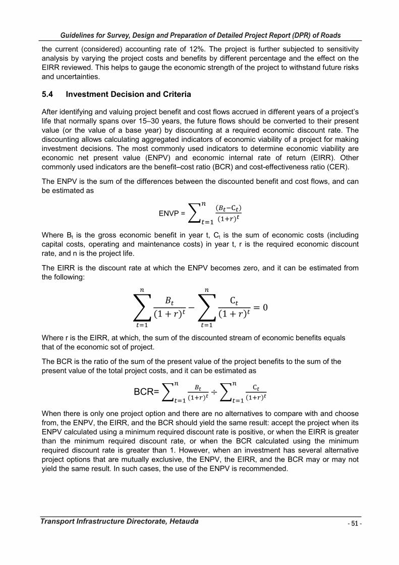
- 51 -
Guidelines for Survey, Design and Preparation of Detailed Project Report (DPR) of Roads
Transport Infrastructure Directorate, Hetauda
Guidelines for Survey Works Including Preparation of Detailed Project Report (DPR) of Roads
Transport Infrastructure Directorate, Hetauda 51
the current (considered) accounting rate of 12%. The project is further subjected to sensitivity analysis by varying the project costs and benefits by different percentage and the effect on the EIRR reviewed. This helps to gauge the economic strength of the project to withstand future risks and uncertainties.
Investment Decision and Criteria 5.4
After identifying and valuing project benefit and cost flows accrued in different years of a project’s life that normally spans over 15–30 years, the future flows should be converted to their present value (or the value of a base year) by discounting at a required economic discount rate. The discounting allows calculating aggregated indicators of economic viability of a project for making investment decisions. The most commonly used indicators to determine economic viability are economic net present value (ENPV) and economic internal rate of return (EIRR). Other commonly used indicators are the benefit–cost ratio (BCR) and cost-effectiveness ratio (CER).
The ENPV is the sum of the differences between the discounted benefit and cost flows, and can be estimated as
ENVP = �(�����)
(���)�
�
���
Where Bt is the gross economic benefit in year t, Ct is the sum of economic costs (including capital costs, operating and maintenance costs) in year t, r is the required economic discount rate, and n is the project life.
The EIRR is the discount rate at which the ENPV becomes zero, and it can be estimated from the following:
���
(1 + �)�
�
���
−�C�
(1 + �)�
�
���
= 0
Where r is the EIRR, at which, the sum of the discounted stream of economic benefits equals that of the economic sot of project.
The BCR is the ratio of the sum of the present value of the project benefits to the sum of the present value of the total project costs, and it can be estimated as
BCR= ���
(���)�
�
���÷�
��
(���)�
�
���
When there is only one project option and there are no alternatives to compare with and choose from, the ENPV, the EIRR, and the BCR should yield the same result: accept the project when its ENPV calculated using a minimum required discount rate is positive, or when the EIRR is greater than the minimum required discount rate, or when the BCR calculated using the minimum required discount rate is greater than 1. However, when an investment has several alternative project options that are mutually exclusive, the ENPV, the EIRR, and the BCR may or may not yield the same result. In such cases, the use of the ENPV is recommended.
- 52 -
Guidelines for Survey, Design and Preparation of Detailed Project Report (DPR) of Roads
Transport Infrastructure Directorate, Hetauda
Guidelines for Survey Works Including Preparation of Detailed Project Report (DPR) of Roads
Transport Infrastructure Directorate, Hetauda 52
6 ENVIRONMENTAL ASSESSMENT
The Environmental Assessment or Environmental Study has become an integral part of highway
project preparation work. The main purpose of assessment is to identify the environmental
impact of the project and its different alternatives, their significance and severance, proposed
mitigation measures and provide information for taking decision regarding the overall
acceptability of the project from environmental angle.
Environmental Assessment of the project shall be undertaken as per provisions of applicable
Laws on Environment Protection Act 2077 of the Bagmati Province Government and identify a
measures to reduce/eliminate the adverse impact identified during environmental study. The
Environmental Study means a Brief Environmental Study (BES), an Initial Environmental
Examination (IEE) and an Environmental Impact Assessment (EIA).
It is necessary to address the issues of environmental aspects for environmentally-friendly
sound and sustainable planning, designing, and construction of road structures. The
environmental issues are, but not limited to, preservation of natural landscape, forest, and
existing monuments, the arrangement of construction materials and techniques, construction of
cross drainage structures, management of mucks and by-product waste, bio-engineering for
slope protection, conservation of the aquatic and terrestrial community, environmental pollution,
health and safety of construction workers and the road users, etc.
Different environmental interventions shall be proposed for the entire project cycle of the project
road e.g. landslide and slope protection, cross drainage and flood control structures, minimal
removal of trees and vegetation, use of eco-friendly construction materials and techniques,
health and safety precautions for the construction and operation phases. The intervening
measures are either preventive or corrective or compensatory depending upon the nature of the
impact and its gravity. These interventions have to be kept in mind during the entire project
cycle of the project.
Moreover, an environmental assessment shall include the mitigation measures for the potential
impacts of road construction, criteria of monitoring of the mitigation measures employed in the
subproject, Environmental Management Plan (EMP), and the budgetary arrangements for
implementing the EMP.
Guidelines for Survey Works Including Preparation of Detailed Project Report (DPR) of Roads
Transport Infrastructure Directorate, Hetauda 53
7 SOCIAL ASSESSMENT
The social assessment should be carried out especially the persons affected due to the Project
and requiring resettlement and rehabilitation. GoN rehabilitation and resettlement guidelines
should be the basis for undertaking the assessment. Plan for resettlement and land acquisition
shall be prepared if required, which shall include the following:
Draft Resettlement and Land Acquisition Plan;
The social assessments should include gender and local aspects;
Scope and magnitude of likely resettlement and land acquisition effects, likely losses of
households, lands, business, and income opportunities, as well as affected community
assets and public buildings;
Development of an entitlement matrix i) in consultation with local stakeholders, government
and the Authority, ii) socio-economic surveys, and iii) inventories of losses that will
determine the amount of compensation following the guidelines and policies of the
Government;

- 53 -
Guidelines for Survey, Design and Preparation of Detailed Project Report (DPR) of Roads
Transport Infrastructure Directorate, Hetauda
Guidelines for Survey Works Including Preparation of Detailed Project Report (DPR) of Roads
Transport Infrastructure Directorate, Hetauda 53
7 SOCIAL ASSESSMENT
The social assessment should be carried out especially the persons affected due to the Project
and requiring resettlement and rehabilitation. GoN rehabilitation and resettlement guidelines
should be the basis for undertaking the assessment. Plan for resettlement and land acquisition
shall be prepared if required, which shall include the following:
Draft Resettlement and Land Acquisition Plan;
The social assessments should include gender and local aspects;
Scope and magnitude of likely resettlement and land acquisition effects, likely losses of
households, lands, business, and income opportunities, as well as affected community
assets and public buildings;
Development of an entitlement matrix i) in consultation with local stakeholders, government
and the Authority, ii) socio-economic surveys, and iii) inventories of losses that will
determine the amount of compensation following the guidelines and policies of the
Government;
- 54 -
Guidelines for Survey, Design and Preparation of Detailed Project Report (DPR) of Roads
Transport Infrastructure Directorate, Hetauda
Guidelines for Survey Works Including Preparation of Detailed Project Report (DPR) of Roads
Transport Infrastructure Directorate, Hetauda 54
8 PREPRATION AND PRESENTATION OF PROJECT DOCUMENTS DETAILED PROJECT REPORT
General 8.1
The project data collected during the survey and investigation together with the detailed design,
estimate, drawing and economic and financial assessment should be presented in proper form
for full appreciation by TID/IDOs. These should be prepared in three parts under the following
headings which when read together will constitute the completer project documents:
I. Volume I- Main Report
II. Volume II – Drawing
III. Volume III- Cost Estimate
Details to be presented in each part are brought out in subsequent paragraphs for guidance. It
should, however, be understood that the extent of detailing of aspect would depend upon the
size of concerned project and its scopes, e.g. whether new construction or improvement to an
existing road.
Main Report 8.2
The project report is most important project document and should contain information under the
following headings:
Acknowledgments
Executive Summary
Salient Features
Introduction
Socio-Economic Profile
Traffic Surveys including traffic forecast
Hydrology and Meteorology
Geology and Geotechnical Investigation
Engineering Surveys and Investigations
Detailed Engineering Design
Environmental and Social Consideration
Cost Estimates
Economic and financial analysis
Construction Programme
Conclusion and Recommendation
Drawings 8.3The drawings should be prepared as described in the Chapter 4.3.
Cost Estimates 8.4The project estimate should give a clear picture of the financial commitment involved and should
be realistic. This is possible only if the items of work are carefully listed, the quantities
determined to a reasonable degree of accuracy, and the rates provided on realistic basis. The
detailed for cost estimate must be as described in Chapter 4.4.
Guidelines for Survey Works Including Preparation of Detailed Project Report (DPR) of Roads
Transport Infrastructure Directorate, Hetauda 55
BIBLIOGRAPHY
Agus Suharyanto 2016. Prediction of Flood Area based on the occurrence of Rainfall Intensity.
Bagmati Province Road Standard 2076.
Bagmati Province, Nepal. Environmental Protection Act 2077.
Department of Local Infrastructure (DOLI) (January 2019). Provincial and Municipal Road
Standards.
Department of Local Infrastructure (DOLI), Project for Strengthening the National Rural Transport
Program (SNRTP) 2018. Project Operation Manual (Version-3).
Department of Road, Nepal. Guideline to Road Slope Protection Work, 2003.
Department of Road, Nepal. Roadside Geotechnical problems, 2007. A Practical Guide to the
Their Solution.
Department of Road. Roadside Bio-engineering. 2002
Indian Road Congress 2014. IRC: SP: 42-2014. Guideline of Road Drainage.
Department of Local Infrastructure Development and Agricultural Roads (DOLIDAR).
Infrastructure Interim Guideline for District Transport Master Plan (DTMP) Preparation.
Department of Local Infrastructure Development and Agricultural Roads (DOLIDAR). Quality
Control Handbook for Rural Road Construction and Maintenance Volume I and II.
Department of Local Infrastructure Development and Agricultural Roads (DOLIDAR). (December
2014). Nepal Rural Road Standard, 2055, Second Revision 2071.
Ministry of Physical Infrastructure and Transport, Department of Road, Planning and Design
Branch, Road and Traffic Unit. Nepal Road Standard 2070. Government of Nepal
- 55 -
Guidelines for Survey, Design and Preparation of Detailed Project Report (DPR) of Roads
Transport Infrastructure Directorate, Hetauda
Guidelines for Survey Works Including Preparation of Detailed Project Report (DPR) of Roads
Transport Infrastructure Directorate, Hetauda 55
BIBLIOGRAPHY
Agus Suharyanto 2016. Prediction of Flood Area based on the occurrence of Rainfall Intensity.
Bagmati Province Road Standard 2076.
Bagmati Province, Nepal. Environmental Protection Act 2077.
Department of Local Infrastructure (DOLI) (January 2019). Provincial and Municipal Road
Standards.
Department of Local Infrastructure (DOLI), Project for Strengthening the National Rural Transport
Program (SNRTP) 2018. Project Operation Manual (Version-3).
Department of Road, Nepal. Guideline to Road Slope Protection Work, 2003.
Department of Road, Nepal. Roadside Geotechnical problems, 2007. A Practical Guide to the
Their Solution.
Department of Road. Roadside Bio-engineering. 2002
Indian Road Congress 2014. IRC: SP: 42-2014. Guideline of Road Drainage.
Department of Local Infrastructure Development and Agricultural Roads (DOLIDAR).
Infrastructure Interim Guideline for District Transport Master Plan (DTMP) Preparation.
Department of Local Infrastructure Development and Agricultural Roads (DOLIDAR). Quality
Control Handbook for Rural Road Construction and Maintenance Volume I and II.
Department of Local Infrastructure Development and Agricultural Roads (DOLIDAR). (December
2014). Nepal Rural Road Standard, 2055, Second Revision 2071.
Ministry of Physical Infrastructure and Transport, Department of Road, Planning and Design
Branch, Road and Traffic Unit. Nepal Road Standard 2070. Government of Nepal
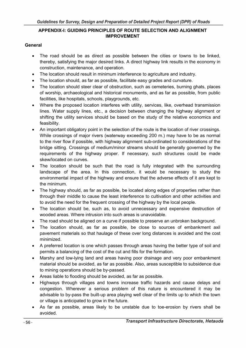
- 56 -
Guidelines for Survey, Design and Preparation of Detailed Project Report (DPR) of Roads
Transport Infrastructure Directorate, Hetauda
Guidelines for Survey Works Including Preparation of Detailed Project Report (DPR) of Roads
Transport Infrastructure Directorate, Hetauda 56
APPENDIX-I: GUIDING PRINCIPLES OF ROUTE SELECTION AND ALIGNMENT IMPROVEMENT
General
The road should be as direct as possible between the cities or towns to be linked,
thereby, satisfying the major desired links. A direct highway link results in the economy in
construction, maintenance, and operation.
The location should result in minimum interference to agriculture and industry.
The location should, as far as possible, facilitate easy grades and curvature.
The location should steer clear of obstruction, such as cemeteries, burning ghats, places
of worship, archaeological and historical monuments, and as far as possible, from public
facilities, like hospitals, schools, playgrounds, etc.
Where the proposed location interferes with utility, services, like, overhead transmission
lines. Water supply lines, etc., a decision between changing the highway alignment or
shifting the utility services should be based on the study of the relative economics and
feasibility.
An important obligatory point in the selection of the route is the location of river crossings.
While crossings of major rivers (waterway exceeding 200 m.) may have to be as normal
to the river flow if possible, with highway alignment sub-ordinated to considerations of the
bridge sitting. Crossings of medium/minor streams should be generally governed by the
requirements of the highway proper. If necessary, such structures could be made
skew/located on curves.
The location should be such that the road is fully integrated with the surrounding
landscape of the area. In this connection, it would be necessary to study the
environmental impact of the highway and ensure that the adverse effects of it are kept to
the minimum.
The highway should, as far as possible, be located along edges of properties rather than
through their middle to cause the least interference to cultivation and other activities and
to avoid the need for the frequent crossing of the highway by the local people.
The location should be, such as, to avoid unnecessary and expensive destruction of
wooded areas. Where intrusion into such areas is unavoidable.
The road should be aligned on a curve if possible to preserve an unbroken background.
The location should, as far as possible, be close to sources of embankment axil
pavement materials so that haulage of these over long distances is avoided and the cost
minimized.
A preferred location is one which passes through areas having the better type of soil and
permits a balancing of the cost of the cut and fills for the formation.
Marshy and low-lying land and areas having poor drainage and very poor embankment
material should be avoided, as far as possible. Also, areas susceptible to subsidence due
to mining operations should be by-passed.
Areas liable to flooding should be avoided, as far as possible.
Highways through villages and towns increase traffic hazards and cause delays and
congestion. Wherever a serious problem of this nature is encountered it may be
advisable to by-pass the built-up area playing well clear of the limits up to which the town
or village is anticipated to grow in the future.
As far as possible, areas likely to be unstable due to toe-erosion by rivers shall be
avoided.
Guidelines for Survey Works Including Preparation of Detailed Project Report (DPR) of Roads
Transport Infrastructure Directorate, Hetauda 57
Special Problems of Locating in Hilly Areas
The route should enable the ruling gradient to be attained in most of the length.
Steep terrain and other inaccessible areas should be avoided, as far as possible.
Unstable hilly features, areas having frequent landslide or settlement problems, and
upslope benched agricultural field with potential for standing water may be avoided as far
as possible.
Locations, along a river valley, have the inherent advantage of comparatively gentle
gradients, proximity of inhabited villages, and easy supply of water for construction
purposes. However, this solution is be-set with disadvantages, such as the need for a
large number of cross-drainage structures and protective works against erosion. It would,
therefore, be necessary to take the various aspects into account before making the final
selection.
The alignment should involve the least number of hairpin bends. Where unavoidable, the
bends should be located on stable and gentle hill slopes.
In certain cases, it may be expedient to negotiate high mountain ranges through tunnels.
For such cases, the decision should be based on relative economics or strategic
considerations.
In crossing mountain ridges, the location should be such that the highway preferably
crosses the ridge at their lowest elevation.
An alignment likely to receive plenty of sunlight should receive due to preference over the
one which will be in shade.
Areas liable to snowdrift should be avoided.
As far as possible, needless rise and fall must be avoided, especially where the general
purpose of the route is to gain elevation from a lower point to a higher point.
Areas of valuable natural resources and wildlife sanctuaries shall be avoided.
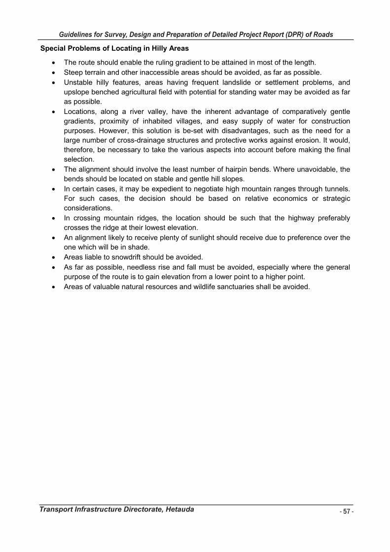
- 57 -
Guidelines for Survey, Design and Preparation of Detailed Project Report (DPR) of Roads
Transport Infrastructure Directorate, Hetauda
Guidelines for Survey Works Including Preparation of Detailed Project Report (DPR) of Roads
Transport Infrastructure Directorate, Hetauda 57
Special Problems of Locating in Hilly Areas
The route should enable the ruling gradient to be attained in most of the length.
Steep terrain and other inaccessible areas should be avoided, as far as possible.
Unstable hilly features, areas having frequent landslide or settlement problems, and
upslope benched agricultural field with potential for standing water may be avoided as far
as possible.
Locations, along a river valley, have the inherent advantage of comparatively gentle
gradients, proximity of inhabited villages, and easy supply of water for construction
purposes. However, this solution is be-set with disadvantages, such as the need for a
large number of cross-drainage structures and protective works against erosion. It would,
therefore, be necessary to take the various aspects into account before making the final
selection.
The alignment should involve the least number of hairpin bends. Where unavoidable, the
bends should be located on stable and gentle hill slopes.
In certain cases, it may be expedient to negotiate high mountain ranges through tunnels.
For such cases, the decision should be based on relative economics or strategic
considerations.
In crossing mountain ridges, the location should be such that the highway preferably
crosses the ridge at their lowest elevation.
An alignment likely to receive plenty of sunlight should receive due to preference over the
one which will be in shade.
Areas liable to snowdrift should be avoided.
As far as possible, needless rise and fall must be avoided, especially where the general
purpose of the route is to gain elevation from a lower point to a higher point.
Areas of valuable natural resources and wildlife sanctuaries shall be avoided.
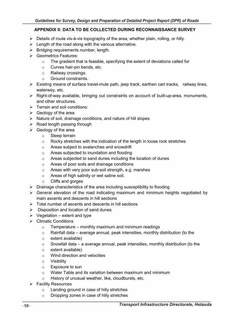
- 58 -
Guidelines for Survey, Design and Preparation of Detailed Project Report (DPR) of Roads
Transport Infrastructure Directorate, Hetauda
Guidelines for Survey Works Including Preparation of Detailed Project Report (DPR) of Roads
Transport Infrastructure Directorate, Hetauda 58
APPENDIX II: DATA TO BE COLLECTED DURING RECONNAISSANCE SURVEY
Details of route vis-à-vis topography of the area, whether plain, rolling, or hilly.
Length of the road along with the various alternative.
Bridging requirements number, length.
Geometrics Features:
o The gradient that is feasible, specifying the extent of deviations called for
o Curves hair-pin bends, etc.
o Railway crossings.
o Ground constraints.
Existing means of surface travel-mule path, jeep track, earthen cart tracks, railway lines,
waterway, etc.
Right-of-way available, bringing out constraints on account of built-up-area, monuments,
and other structures.
Terrain and soil conditions:
Geology of the area
Nature of soil, drainage conditions, and nature of hill slopes
Road length passing through
Geology of the area
o Steep terrain
o Rocky stretches with the indication of the length in loose rock stretches
o Areas subject to avalanches and snowdrift
o Areas subjected to inundation and flooding
o Areas subjected to sand dunes including the location of dunes
o Areas of poor soils and drainage conditions
o Areas with very poor sub-soil strength, e.g. marshes
o Areas of high salinity or wet saline soil.
o Cliffs and gorges
Drainage characteristics of the area including susceptibility to flooding
General elevation of the road indicating maximum and minimum heights negotiated by
main ascents and descents in hill sections
Total number of ascents and descents in hill sections
Disposition and location of sand dunes
Vegetation – extent and type
Climatic Conditions
o Temperature – monthly maximum and minimum readings
o Rainfall data – average annual, peak intensities, monthly distribution (to the
o extent available)
o Snowfall data – a average annual, peak intensities, monthly distribution (to the
o extent available)
o Wind direction and velocities
o Visibility
o Exposure to sun
o Water Table and its variation between maximum and minimum
o History of unusual weather, like, cloudbursts, etc.
Facility Resources
o Landing ground in case of hilly stretches
o Dropping zones in case of hilly stretches
Guidelines for Survey Works Including Preparation of Detailed Project Report (DPR) of Roads
Transport Infrastructure Directorate, Hetauda 59
o Foodstuffs
o Labour – local availability and need for import
o Construction material timber, bamboo, sand, stones, shingle, etc. with the extent
of
o their availability leads involved and availability of easy access
o Availability of water, especially in arid zones
o Availability of local contractors
Value of land-agriculture land, irrigated land, built-up land, forest land, etc.
The approximate construction cost of various alternatives.
Access points indicating the possibility of induction of equipment.
The period required for construction.
Strategic considerations.
Recreational potential.
Important villages, towns, and marketing centers connected.
Economic factors:
o Population served by the alignment
o The agricultural and economic potential of the area
o Marketing centers
Other major developmental projects being taken up in the area, e.g., railway project
Hydro-electric projects, railway projects, dams, reservoirs, mining/agricultural projects,
etc.
Crossings with Railway Lines and other existing highways.
Location of existing or proposed utilities along the alignment.
The necessity of by-passes for towns and villages.
Position of ancient monuments, burial grounds, cremation grounds, religious structures,
hospitals, and schools.
Ecology and environmental factors.
Aspects of needing coordination with other administrative authorities.
Traffic counts from existing records.
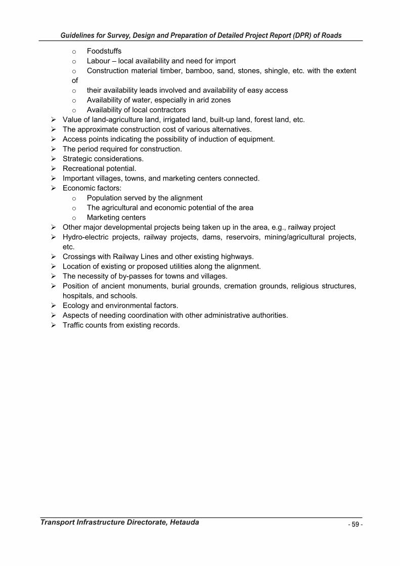
- 59 -
Guidelines for Survey, Design and Preparation of Detailed Project Report (DPR) of Roads
Transport Infrastructure Directorate, Hetauda
Guidelines for Survey Works Including Preparation of Detailed Project Report (DPR) of Roads
Transport Infrastructure Directorate, Hetauda 59
o Foodstuffs
o Labour – local availability and need for import
o Construction material timber, bamboo, sand, stones, shingle, etc. with the extent
of
o their availability leads involved and availability of easy access
o Availability of water, especially in arid zones
o Availability of local contractors
Value of land-agriculture land, irrigated land, built-up land, forest land, etc.
The approximate construction cost of various alternatives.
Access points indicating the possibility of induction of equipment.
The period required for construction.
Strategic considerations.
Recreational potential.
Important villages, towns, and marketing centers connected.
Economic factors:
o Population served by the alignment
o The agricultural and economic potential of the area
o Marketing centers
Other major developmental projects being taken up in the area, e.g., railway project
Hydro-electric projects, railway projects, dams, reservoirs, mining/agricultural projects,
etc.
Crossings with Railway Lines and other existing highways.
Location of existing or proposed utilities along the alignment.
The necessity of by-passes for towns and villages.
Position of ancient monuments, burial grounds, cremation grounds, religious structures,
hospitals, and schools.
Ecology and environmental factors.
Aspects of needing coordination with other administrative authorities.
Traffic counts from existing records.
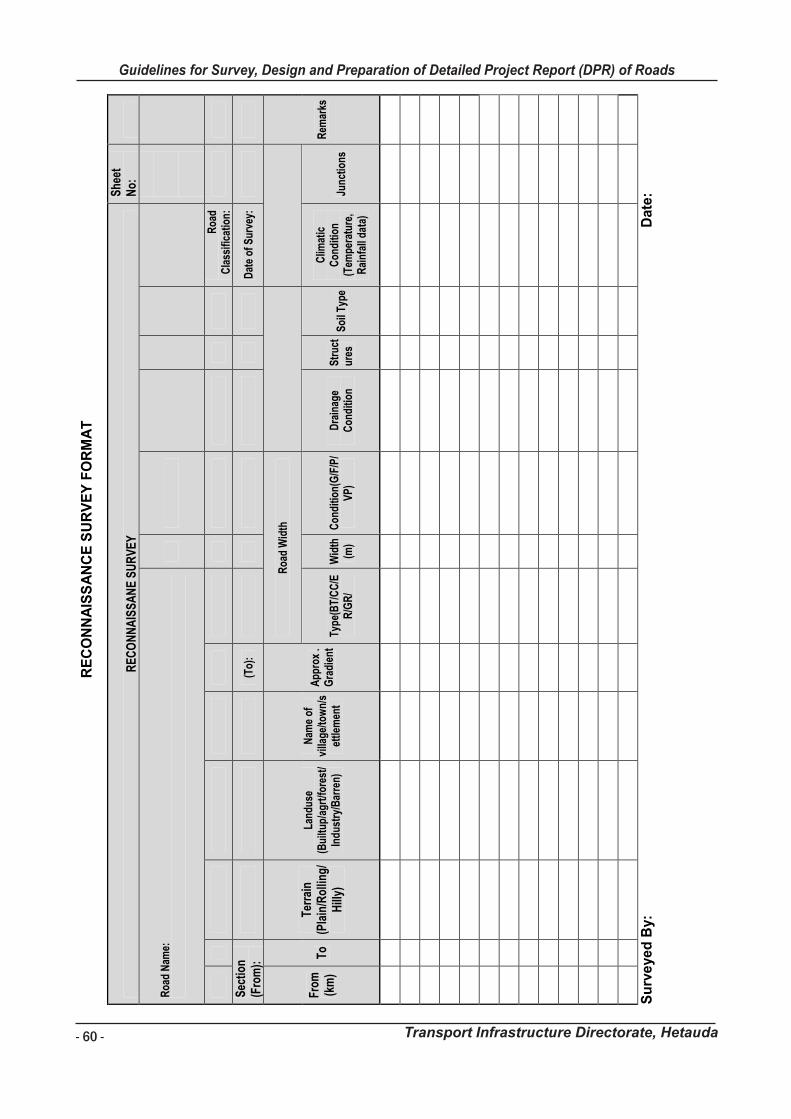
- 60 -
Guidelines for Survey, Design and Preparation of Detailed Project Report (DPR) of Roads
Transport Infrastructure Directorate, Hetauda
Gu
idelin
es f
or
Su
rvey
Wo
rks In
clu
din
g P
rep
ara
tio
n o
f D
eta
iled
Pro
ject
Rep
ort
(D
PR
) o
f R
oad
s
Tra
nsp
ort
In
frastr
uctu
re D
irecto
rate
, H
eta
ud
a
58
RE
CO
NN
AIS
SA
NC
E S
UR
VE
Y F
OR
MA
T
RE
CO
NN
AIS
SA
NE
SU
RV
EY
S
heet
N
o:
Roa
d N
ame:
Roa
d C
lass
ifica
tion:
Sec
tion
(Fro
m):
(To)
:
D
ate
of S
urve
y:
From
(k
m)
To
Terr
ain
(Pla
in/R
ollin
g/H
illy)
Land
use
(Bui
ltup/
agrt
/fore
st/
Indu
stry
/Bar
ren)
Nam
e of
vi
llage
/tow
n/s
ettle
men
t
App
rox
. G
radi
ent
Roa
d W
idth
Rem
arks
Ty
pe(B
T/C
C/E
R/G
R/
Wid
th
(m)
Con
ditio
n(G
/F/P
/V
P)
Dra
inag
e C
ondi
tion
Str
uct
ures
S
oil T
ype
Clim
atic
C
ondi
tion
(Tem
pera
ture
, R
ainf
all d
ata)
Junc
tions
Su
rve
yed
By:
Date
:
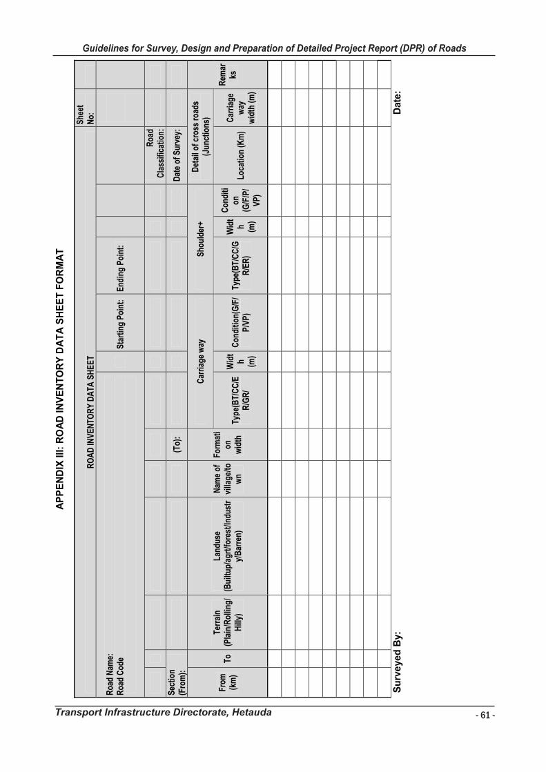
- 61 -
Guidelines for Survey, Design and Preparation of Detailed Project Report (DPR) of Roads
Transport Infrastructure Directorate, Hetauda
Gu
idelin
es f
or
Su
rvey
Wo
rks In
clu
din
g P
rep
ara
tio
n o
f D
eta
iled
Pro
ject
Rep
ort
(D
PR
) o
f R
oad
s
Tra
nsp
ort
In
frastr
uctu
re D
irecto
rate
, H
eta
ud
a
59
AP
PE
ND
IX III
: R
OA
D IN
VE
NT
OR
Y D
AT
A S
HE
ET
FO
RM
AT
RO
AD
INV
EN
TOR
Y D
ATA
SH
EE
T S
heet
N
o:
Roa
d N
ame:
R
oad
Cod
e
S
tart
ing
Poi
nt:
End
ing
Poi
nt:
Roa
d C
lass
ifica
tion:
Sec
tion
(Fro
m):
(To)
:
D
ate
of S
urve
y:
From
(k
m)
To
Terr
ain
(Pla
in/R
ollin
g/H
illy)
Land
use
(Bui
ltup/
agrt
/fore
st/In
dust
ry/
Bar
ren)
Nam
e of
vi
llage
/tow
n
Form
ati
on
wid
th
Car
riag
e w
ay
Sho
ulde
r+
Det
ail o
f cro
ss r
oads
(J
unct
ions
)
Rem
arks
Ty
pe(B
T/C
C/E
R/G
R/
Wid
th (m
)
Con
ditio
n(G
/F/
P/V
P)
Type
(BT/
CC
/GR
/ER
)
Wid
th (m
)
Con
diti
on
(G/F
/P/
VP
)
Loca
tion
(Km
) C
arri
age
way
w
idth
(m)
Su
rve
yed
By:
Date
:
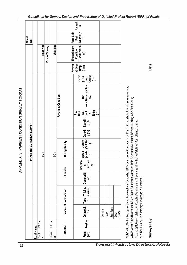
- 62 -
Guidelines for Survey, Design and Preparation of Detailed Project Report (DPR) of Roads
Transport Infrastructure Directorate, Hetauda
Gu
ide
lin
es
fo
r S
urv
ey
Wo
rks I
nc
lud
ing
Pre
pa
rati
on
of
De
tail
ed
Pro
jec
t R
ep
ort
(D
PR
) o
f R
oa
ds
Tra
ns
po
rt I
nfr
as
tru
ctu
re D
irec
tora
te,
He
tau
da
60
AP
PE
ND
IX I
V:
PA
VM
EN
T C
ON
DIT
ION
SU
RV
EY
FO
RM
AT
PA
VE
ME
NT
CO
ND
ITIO
N S
UR
VE
Y
She
et
No:
Roa
d N
ame:
S
ectio
n
(FR
OM
) :
TO
:
R
oad
No:
Dat
e of
Sur
vey:
D
istr
ict
(F
RO
M)
:
TO :
Wea
ther
:
CH
AIN
AG
E
Pav
emen
t Com
posi
tion
Sho
ulde
r R
idin
g Q
ualit
y
Pav
emen
t Con
ditio
n
Pav
eme
nt E
dge
Dro
p (m
m)
Em
bank
men
t C
ondi
tion
(Goo
d/Fa
ir/P
oor
)
Roa
d S
ide
Dra
in
(NE
/PF/
F)*
**
Rem
ark
s
From
(k
m)
To (k
m)
Com
posi
tion
Ty
pe * Th
ickn
ess
(mm
) C
ompo
siti
on
Con
ditio
n (F
air/
Poo
r)
Spe
ed
(Km
/hr)
Qua
lity
(G/F
/P/V
P)
Cra
ckin
g (%
) R
avel
ling
(%)
Pot
H
ole
(No.
an
d %
10
0m ) **
Rut
(N
one/
Mod
erat
e/S
ever
e)
Pat
chin
g (N
o.
and
%10
0m) *
*
Sur
face
B
ase
Sub
-Bas
e
S
ub-
Gra
de
Not
e* -
BU
SG
= B
uilt
up S
pray
Gro
ut; A
C=
Asp
halti
c C
oncr
ete;
SD
C=
Sem
i Den
se C
oncr
ete
; PC
= P
rem
ix C
oncr
ete;
MS
S=
Mix
sea
ling
surfa
ce;
WBM
= W
ater
Bou
nd M
acad
um; D
BM=
Den
se B
itum
inou
s M
acad
um; B
M=
Bitu
min
ous
Mac
adum
; BS=
Bric
k S
olin
g; S
S=
Sto
ne S
olin
g
No.
and
%/1
00 m
= To
tal n
o. o
f Pot
holin
g/P
atch
ing
and
% a
ge a
rea
of P
otho
ling/
Pat
chin
g 10
0m o
f len
gth
of ro
ad
NE=
Non
Exi
stin
g; P
F= P
artia
lly F
unct
iona
l; F=
Fun
ctio
nal
Su
rve
yed
By:
Date
:
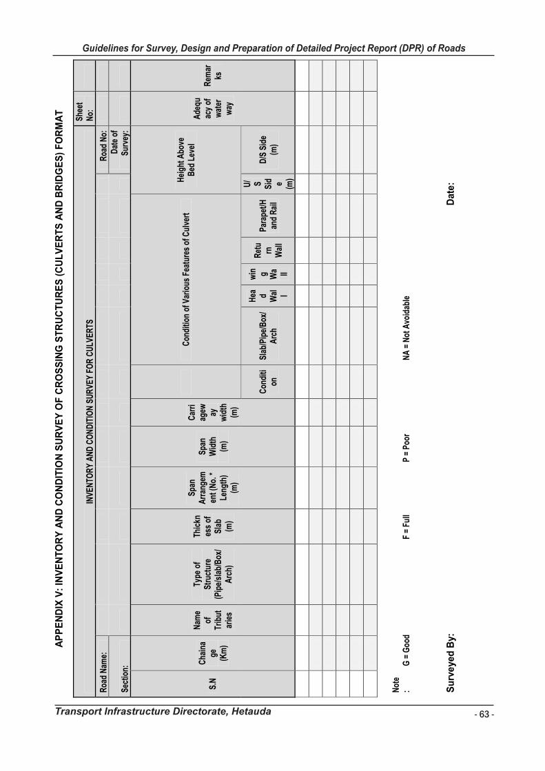
- 63 -
Guidelines for Survey, Design and Preparation of Detailed Project Report (DPR) of Roads
Transport Infrastructure Directorate, Hetauda
Gu
ide
lin
es
fo
r S
urv
ey
Wo
rks I
nc
lud
ing
Pre
pa
rati
on
of
De
tail
ed
Pro
jec
t R
ep
ort
(D
PR
) o
f R
oa
ds
Tra
ns
po
rt I
nfr
as
tru
ctu
re D
irec
tora
te,
He
tau
da
61
AP
PE
ND
IX V
: IN
VE
NT
OR
Y A
ND
CO
ND
ITIO
N S
UR
VE
Y O
F C
RO
SS
ING
ST
RU
CT
UR
ES
(C
UL
VE
RT
S A
ND
BR
IDG
ES
) F
OR
MA
T
INV
EN
TOR
Y A
ND
CO
ND
ITIO
N S
UR
VE
Y F
OR
CU
LVE
RTS
S
heet
N
o:
Roa
d N
ame:
Roa
d N
o:
Sec
tion:
Dat
e of
S
urve
y:
S.N
C
hain
age
(K
m)
Nam
e of
Tr
ibut
arie
s
Type
of
Str
uctu
re
(Pip
e/sl
ab/B
ox/
Arc
h)
Thic
knes
s of
S
lab
(m)
Spa
n A
rran
gem
ent (
No.
*
Leng
th)
(m)
Spa
n W
idth
(m
)
Car
riag
ew ay
wid
th
(m)
C
ondi
tion
of V
ario
us F
eatu
res
of C
ulve
rt
Hei
ght A
bove
B
ed L
evel
A
dequ
acy
of
wat
er
way
Rem
arks
Con
diti
on
Sla
b/P
ipe/
Box
/A
rch
Hea d Wal l
win g Wa ll
Ret
urn
W
all
Par
apet
/Han
d R
ail
U/ S
Sid e (m
)
D/S
Sid
e (m
)
Not
e:
G =
Goo
d
F =
Full
P
= P
oor
NA
= N
ot A
void
able
Su
rve
yed
By:
Date
:
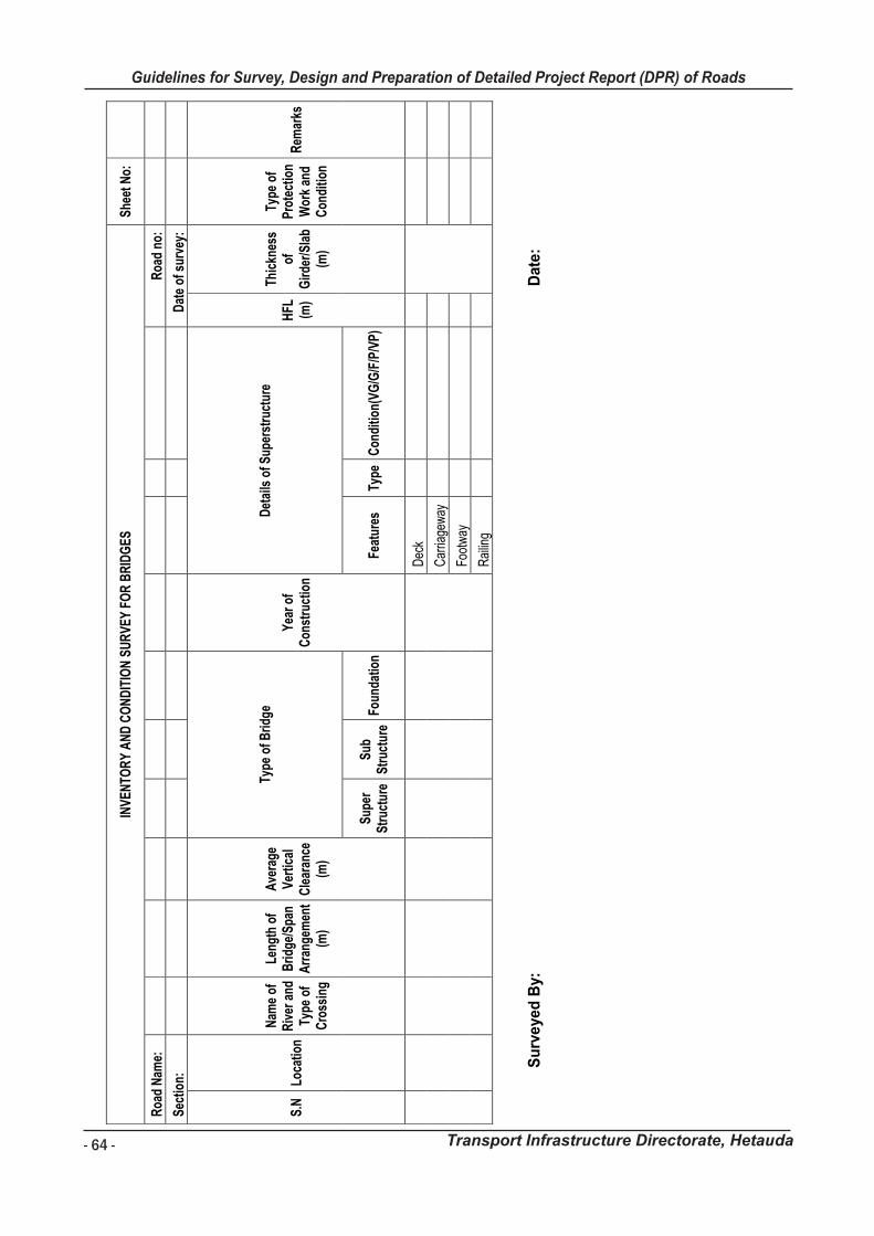
- 64 -
Guidelines for Survey, Design and Preparation of Detailed Project Report (DPR) of Roads
Transport Infrastructure Directorate, Hetauda
Gu
idelin
es f
or
Su
rvey
Wo
rks In
clu
din
g P
rep
ara
tio
n o
f D
eta
iled
Pro
ject
Rep
ort
(D
PR
) o
f R
oad
s
Tra
nsp
ort
In
frastr
uctu
re D
irecto
rate
, H
eta
ud
a
62
INV
EN
TOR
Y A
ND
CO
ND
ITIO
N S
UR
VE
Y F
OR
BR
IDG
ES
S
heet
No:
Roa
d N
ame:
R
oad
no:
Sec
tion:
D
ate
of s
urve
y:
S.N
Lo
catio
n
Nam
e of
R
iver
and
Ty
pe o
f C
ross
ing
Leng
th o
f B
ridge
/Spa
n A
rran
gem
ent
(m)
Ave
rage
V
ertic
al
Cle
aran
ce
(m)
Type
of B
ridge
Yea
r of
Con
stru
ctio
n
Det
ails
of S
uper
stru
ctur
e
HFL
(m
)
Thic
knes
s of
G
irde
r/S
lab
(m)
Type
of
Pro
tect
ion
Wor
k an
d C
ondi
tion
Rem
arks
Sup
er
Str
uctu
re
Sub
S
truc
ture
Fo
unda
tion
Feat
ures
Ty
pe
Con
ditio
n(V
G/G
/F/P
/VP
)
Dec
k
Car
riage
way
Foot
way
Rai
ling
S
urv
eyed
By:
Date
:
Guidelines for Survey Works Including Preparation of Detailed Project Report (DPR) of Roads
Transport Infrastructure Directorate, Hetauda
APPENDIX VI: SURVEY CODES AND MARKINGS
List of Survey to be used as follows: Survey Coding Method
Example
MW/T/E - Top of Masonry wall end
NS/Mill/C - Natural surface at mill corner
Main Code
Description Main Code Description
CL Road Center line BL Baseline Point
RE Right Road Edge ST Traverse Station
LE Left Road Edge FS Fly Stations
SRE Right Road Shoulder
Edge BM Benchmark
SLE Left Road Shoulder Edge
TBM Temporary Benchmark
PRE Right Road Pavement
Edge TK Track Road Centre
PLE Left Road Pavement
Edge TR Tree
JNC Road Junction WL Water Level
DR Drain BDG Bridge
EP Electric Pole F Fill
PC Pipe Culvert CU Cut
SC Slab Culvert CA Canal
BOC Box Culvert TEL Telephone Pole
HW Culvert Head wall RO Rocky Outcrop
NS Natural Surface BO Boulder
PW Parapet Wall W Wall
CH Chainage FE Fence
HC House Corner TOL Toilet
GW Gabion Wall HP Hand Pump
MW Cement Masonry wall PW Parapet Wall
DW Dry Wall CP Catch Pit
HFL High Flood Level FL Normal Flood Level
Kl Stream I Gully Others As instructed by Field Engineer
Description Codes Description Description
Codes Description
C Corner R Right
T Top IL Invert Level
B Bottom DS Downstream
S Start US Upstream
CL Centre Temple Temple
E End Pipal Pipal
L Left Wing Wing Wall/ Guide Wall
BRL Break Line
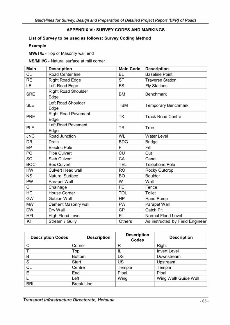
- 65 -
Guidelines for Survey, Design and Preparation of Detailed Project Report (DPR) of Roads
Transport Infrastructure Directorate, Hetauda
Guidelines for Survey Works Including Preparation of Detailed Project Report (DPR) of Roads
Transport Infrastructure Directorate, Hetauda
APPENDIX VI: SURVEY CODES AND MARKINGS
List of Survey to be used as follows: Survey Coding Method
Example
MW/T/E - Top of Masonry wall end
NS/Mill/C - Natural surface at mill corner
Main Code
Description Main Code Description
CL Road Center line BL Baseline Point
RE Right Road Edge ST Traverse Station
LE Left Road Edge FS Fly Stations
SRE Right Road Shoulder
Edge BM Benchmark
SLE Left Road Shoulder Edge
TBM Temporary Benchmark
PRE Right Road Pavement
Edge TK Track Road Centre
PLE Left Road Pavement
Edge TR Tree
JNC Road Junction WL Water Level
DR Drain BDG Bridge
EP Electric Pole F Fill
PC Pipe Culvert CU Cut
SC Slab Culvert CA Canal
BOC Box Culvert TEL Telephone Pole
HW Culvert Head wall RO Rocky Outcrop
NS Natural Surface BO Boulder
PW Parapet Wall W Wall
CH Chainage FE Fence
HC House Corner TOL Toilet
GW Gabion Wall HP Hand Pump
MW Cement Masonry wall PW Parapet Wall
DW Dry Wall CP Catch Pit
HFL High Flood Level FL Normal Flood Level
Kl Stream I Gully Others As instructed by Field Engineer
Description Codes Description Description
Codes Description
C Corner R Right
T Top IL Invert Level
B Bottom DS Downstream
S Start US Upstream
CL Centre Temple Temple
E End Pipal Pipal
L Left Wing Wing Wall/ Guide Wall
BRL Break Line
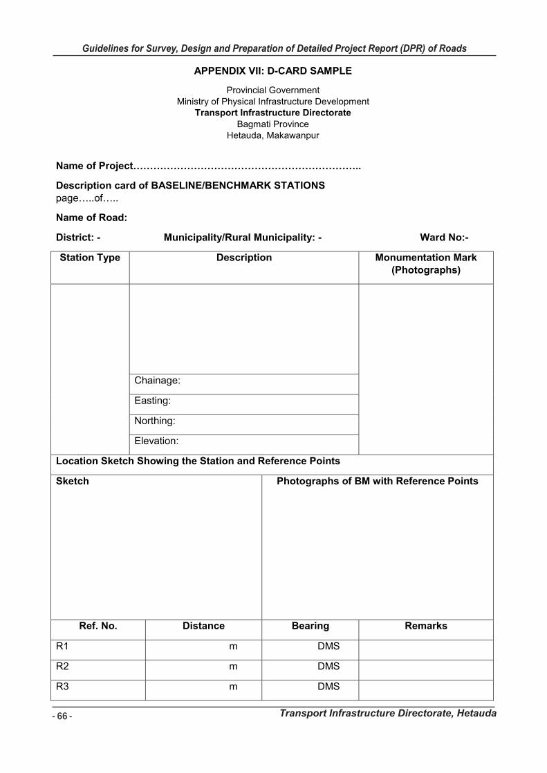
- 66 -
Guidelines for Survey, Design and Preparation of Detailed Project Report (DPR) of Roads
Transport Infrastructure Directorate, Hetauda
Guidelines for Survey Works Including Preparation of Detailed Project Report (DPR) of Roads
Transport Infrastructure Directorate, Hetauda
APPENDIX VII: D-CARD SAMPLE
Provincial Government
Ministry of Physical Infrastructure Development Transport Infrastructure Directorate
Bagmati Province Hetauda, Makawanpur
Name of Project…………………………………………………………..
Description card of BASELINE/BENCHMARK STATIONS page…..of…..
Name of Road:
District: - Municipality/Rural Municipality: - Ward No:-
Station Type Description Monumentation Mark (Photographs)
Chainage:
Easting:
Northing:
Elevation:
Location Sketch Showing the Station and Reference Points
Sketch
Photographs of BM with Reference Points
Ref. No. Distance Bearing Remarks
R1 m DMS
R2 m DMS
R3 m DMS
Guidelines for Survey Works Including Preparation of Detailed Project Report (DPR) of Roads
Transport Infrastructure Directorate, Hetauda
APPENDIX VIII: TREE DATA COLLECTION WITHIN ALIGNMENT FORMAT
SN CH Location Left/Right Type of
tree Girth cms Ownership
Remarks (Road/RoW)
Surveyed By: Date:

- 67 -
Guidelines for Survey, Design and Preparation of Detailed Project Report (DPR) of Roads
Transport Infrastructure Directorate, Hetauda
Guidelines for Survey Works Including Preparation of Detailed Project Report (DPR) of Roads
Transport Infrastructure Directorate, Hetauda
APPENDIX VIII: TREE DATA COLLECTION WITHIN ALIGNMENT FORMAT
SN CH Location Left/Right Type of
tree Girth cms Ownership
Remarks (Road/RoW)
Surveyed By: Date:
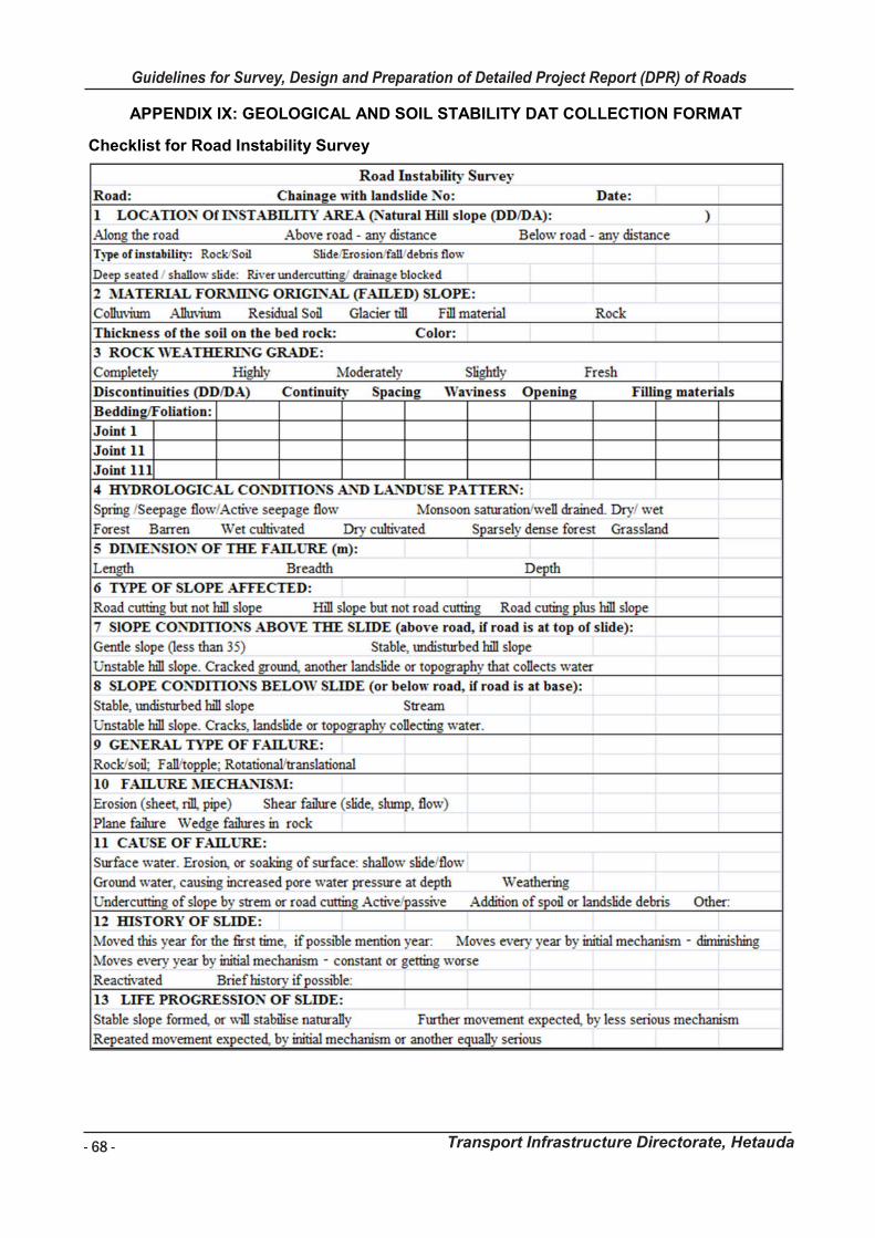
- 68 -
Guidelines for Survey, Design and Preparation of Detailed Project Report (DPR) of Roads
Transport Infrastructure Directorate, Hetauda
Guidelines for Survey Works Including Preparation of Detailed Project Report (DPR) of Roads
Transport Infrastructure Directorate, Hetauda
APPENDIX IX: GEOLOGICAL AND SOIL STABILITY DAT COLLECTION FORMAT
Checklist for Road Instability Survey
Guidelines for Survey Works Including Preparation of Detailed Project Report (DPR) of Roads
Transport Infrastructure Directorate, Hetauda
Engineering geological log of the road alignment

- 69 -
Guidelines for Survey, Design and Preparation of Detailed Project Report (DPR) of Roads
Transport Infrastructure Directorate, Hetauda
Guidelines for Survey Works Including Preparation of Detailed Project Report (DPR) of Roads
Transport Infrastructure Directorate, Hetauda
Engineering geological log of the road alignment
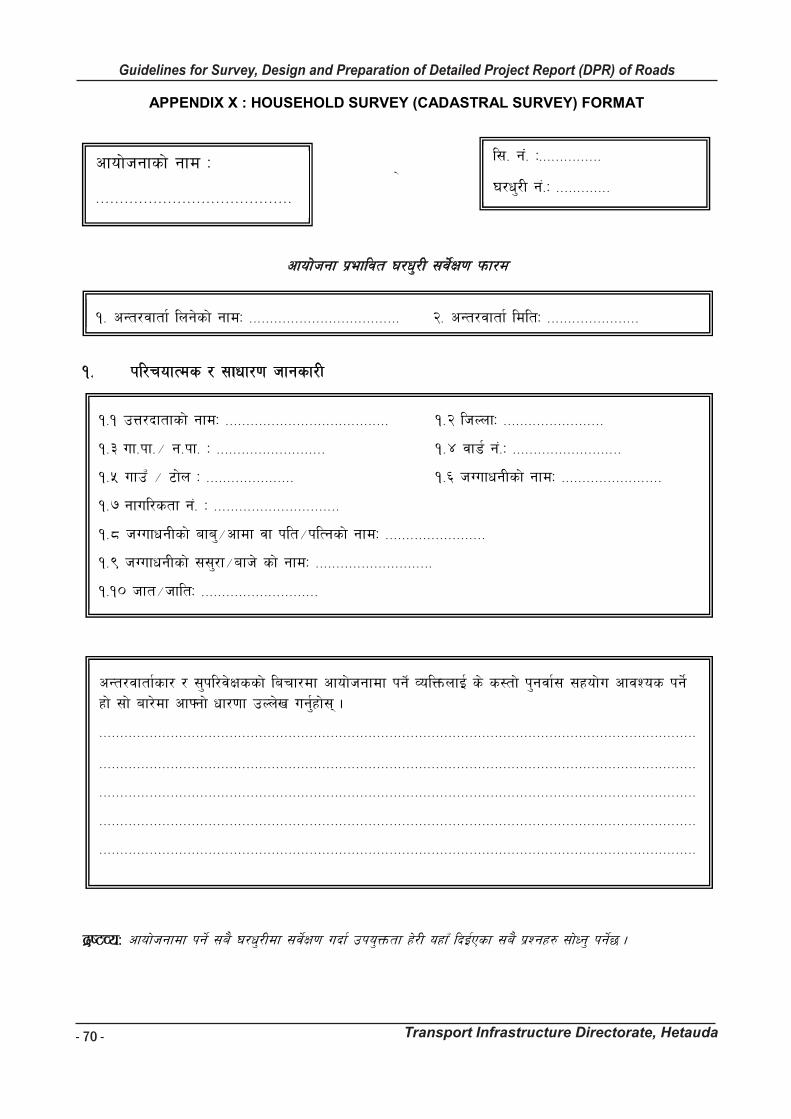
- 70 -
Guidelines for Survey, Design and Preparation of Detailed Project Report (DPR) of Roads
Transport Infrastructure Directorate, Hetauda
Guidelines for Survey Works Including Preparation of Detailed Project Report (DPR) of Roads
Transport Infrastructure Directorate, Hetauda
APPENDIX X : HOUSEHOLD SURVEY (CADASTRAL SURVEY) FORMAT
\
cfof]hgf k|efljt 3/w'/L ;j]{If0f kmf/d
!= kl/rofTds / ;fwf/0f hfgsf/L
b|i6JoM cfof]hgfdf kg]{ ;a} 3/w'/Ldf ;j]{If0f ubf{ pko'Qmtf x]/L oxfF lbO{Psf ;a} k|Zgx? ;f]Wg' kg]{5 .
cfof]hgfsf] gfd M
=========================================
l;= g++= M===============
3/w'/L g+=M =============
!= cGt/jftf{ lng]sf] gfdM ==================================== @= cGt/jftf{ ldltM ======================
!=! pQ/bftfsf] gfdM ======================================= !=@ lhNnfM ========================
!=# uf=kf=÷ g=kf= M ========================== !=$ jf8{ g+=M ==========================
!=% ufpF ÷ 6f]n M ===================== !=^ hUufwgLsf] gfdM ========================
!=& gful/stf g+= M ==============================
!=* hUufwgLsf] afa'÷cfdf jf klt÷klTgsf] gfdM ========================
!=( hUufwgLsf] ;;'/f÷afh] sf] gfdM ============================
!=!) hft÷hfltM ============================
cGt/jftf{sf/ / ;'kl/j]Ifssf] larf/df cfof]hgfdf kg]{ JolQmnfO{ s] s:tf] k'gjf{; ;xof]u cfjZos kg]{ xf] ;f] af/]df cfˆgf] wf/0ff pNn]v ug{'xf];\ .
==============================================================================================================================================
==============================================================================================================================================
==============================================================================================================================================
==============================================================================================================================================
==============================================================================================================================================
=================================
Guidelines for Survey Works Including Preparation of Detailed Project Report (DPR) of Roads
Transport Infrastructure Directorate, Hetauda
@= kfl/jf/Ls ljj/0f
@=! hDdf kl/jf/ ;+Vof ====================
qm=
;+=
kl/jf/sf ;b:osf] gfd lnË pd]/ lzIff
-^ aif{ dflysf]_
cfly{s ultlawL
ut ! jif{ leq Ps dlxgf eGbf al9 ;do 3/ 5f]8L aflx/ uPsf]
eP
3/d'nLsf] gftf
s}lkmot
3/ 5f]8L hfg'sf] pb]Zo
3/ 5f]l8
uPsf] 7fpF
!
@
#
$
%
^
&
*
(
!)
!!
!@
!#
!$
!%

- 71 -
Guidelines for Survey, Design and Preparation of Detailed Project Report (DPR) of Roads
Transport Infrastructure Directorate, Hetauda
Guidelines for Survey Works Including Preparation of Detailed Project Report (DPR) of Roads
Transport Infrastructure Directorate, Hetauda
@= kfl/jf/Ls ljj/0f
@=! hDdf kl/jf/ ;+Vof ====================
qm=
;+=
kl/jf/sf ;b:osf] gfd lnË pd]/ lzIff
-^ aif{ dflysf]_
cfly{s ultlawL
ut ! jif{ leq Ps dlxgf eGbf al9 ;do 3/ 5f]8L aflx/ uPsf]
eP
3/d'nLsf] gftf
s}lkmot
3/ 5f]8L hfg'sf] pb]Zo
3/ 5f]l8
uPsf] 7fpF
!
@
#
$
%
^
&
*
(
!)
!!
!@
!#
!$
!%
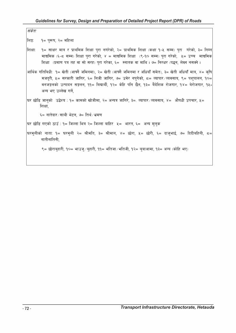
- 72 -
Guidelines for Survey, Design and Preparation of Detailed Project Report (DPR) of Roads
Transport Infrastructure Directorate, Hetauda
Guidelines for Survey Works Including Preparation of Detailed Project Report (DPR) of Roads
Transport Infrastructure Directorate, Hetauda
;+s]tM
lnËM !Ö k'¿if, @Ö dlxnf
lzIffM !Ö ;fIf/ dfq / k|fylds lzIff k'/f gu/]sf], @Ö k|fylds lzIff -sIff !–% ;Dd_ k'/f u/]sf], #Ö lgDg
dfBlds -^–* ;Dd_ lzIff k'/f u/]sf], $ Ö dfBlds lzIff -(–!) ;Dd_ k'/f u/]sf], %Ö pRr dfBlds
lzIff -k|df0f kq tx jf ;f] ;/x_ k'/f u/]sf, ^Ö :gfts jf dfly . &Ö lg/If/ -k4\g, n]Vg g;Sg] .
cfly{s ultlawLM !Ö v]tL -cfˆg} hldgdf_, @Ö v]tL -cfˆg} hldgdf / clwof“ ;d]t_, #Ö v]tL clwof“ dfq, $Ö s[lif
dhb'/L, %Ö ;/sf/L hflu/, ^Ö lghL hflu/, &Ö pd]/ gk'u]sf], *Ö Jofkf/÷Joj;fo, (Ö kz'kfng, !)Ö
jghËnsf] pTkfbg ;Íng, !!Ö laBfyL{, !@Ö s]lx klg 5}g, !#Ö a}b]lzs /f]huf/, !$Ö a]/f]huf/, !%≠ cGo eP pNn]v ug]{,
3/ 5f]l8 hfg'sf] p4]Zo M !Ö sfdsf] vf]hLdf, @Ö cGoq hflu/], #Ö= Jofkf/÷Joj;fo, $Ö cf}ifwL pkrf/, %Ö lzIff,
^Ö gft]bf/÷;fyL e]6g, &Ö lty{÷e|d0f
3/ 5f]l8 uPsf] 7fpF M !Ö lhNnf leq @Ö lhNnf aflx/ %Ö ef/t, ^Ö cGo d'n's
3/d'nLsf] gftfM !Ö 3/d'nL @Ö >Ldlt, #Ö >Ldfg, $Ö 5f]/f, %Ö 5f]/L, ^Ö bfh'efO{, &Ö lbbLalxgL, *Ö
gftLgfltgL,
(Ö 5f]/fa'xf/L, !)Ö efph'÷a'xf/L, !!Ö elthf÷elthL, !@Ö a'afcfdf, !#Ö cGo -sf]lx eP_
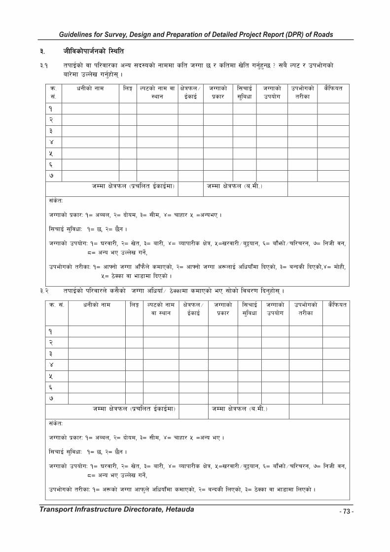
- 73 -
Guidelines for Survey, Design and Preparation of Detailed Project Report (DPR) of Roads
Transport Infrastructure Directorate, Hetauda
Guidelines for Survey Works Including Preparation of Detailed Project Report (DPR) of Roads
Transport Infrastructure Directorate, Hetauda
#= hLljsf]kfh{gsf] l:ylt
#=! tkfO{sf] jf kl/jf/sf cGo ;b:osf] gfddf slt hUuf 5 / sltdf v]lt ug{'x'G5 < ;a} Nk6 / pkef]usf] af/]df pNn]v ug{'xf];\ .
qm= ;+=
wgLsf] gfd lnË Nk6sf] gfd jf :yfg
If]qkmn÷ O{sfO{
hUufsf] k|sf/
l;rfO{ ;'lawf
hUufsf] pkof]u
pkef]usf] t/Lsf
s}lkmot
!
@
#
$
%
^
& hDdf If]qkmn -k|rlnt O{sfO{df_ hDdf If]qkmn -a=dL=_
;+s]tM
hUufsf] k|sf/M !Ö cAan, @Ö bf]od, #Ö ;Ld, $Ö rfxf/ % ÖcGoeP .
l;rfO{ ;'ljwfM !Ö 5, @Ö 5}g .
hUufsf] pkof]uM !Ö 3/jf/L, @Ö v]t, #Ö af/L, $Ö Jofkf/Ls If]q, %Öv/jf/L÷a'§ofg, ^Ö af“emf]÷rl/r/g, &Ö lghL jg,
*Ö cGo eP pNn]v ug]{,
pkef]usf] t/LsfM !Ö cfˆgf] hUuf cf“km}n] sdfPsf], @Ö cfˆgf] hUuf c¿nfO{ clwof “df lbPsf], #Ö aGbsL lbPsf]],$Ö df]xL,
%Ö 7]Ssf jf ef8fdf lbPsf] .
#=@ tkfO{sf] kl/jf/n] s;}sf] hUuf clwofF÷ 7]Ssfdf sdfPsf] eP ;f]sf] lja/0f lbg'xf];\ .
qm= ;+= wgLsf] gfd lnË Nk6sf] gfd jf :yfg
If]qkmn÷ O{sfO{
hUufsf] k|sf/
l;rfO{ ;'lawf
hUufsf] pkof]u
pkef]usf] t/Lsf
s}lkmot
!
@
#
$
%
^
& hDdf If]qkmn -k|rlnt O{sfO{df_ hDdf If]qkmn -a=dL=_
;+s]tM
hUufsf] k|sf/M !Ö cAan, @Ö bf]od, #Ö ;Ld, $Ö rfxf/ % ÖcGo eP .
l;rfO{ ;'ljwfM !Ö 5, @Ö 5}g .
hUufsf] pkof]uM !Ö 3/jf/L, @Ö v]t, #Ö af/L, $Ö Jofkf/Ls If]q, %Öv/jf/L÷a'§ofg, ^Ö af“emf]÷rl/r/g, &Ö lghL jg,
*Ö cGo eP pNn]v ug]{,
pkef]usf] t/LsfM !Ö c¿sf] hUuf cfkm'n] clwof “df sdfPsf], @Ö aGbsL lnPsf], #Ö 7]Ssf jf ef8fdf lnPsf] .
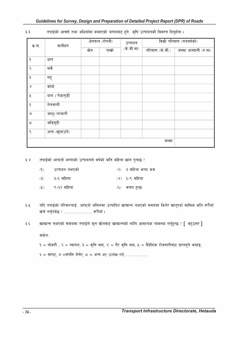
- 74 -
Guidelines for Survey, Design and Preparation of Detailed Project Report (DPR) of Roads
Transport Infrastructure Directorate, Hetauda
Guidelines for Survey Works Including Preparation of Detailed Project Report (DPR) of Roads
Transport Infrastructure Directorate, Hetauda
#=# tkfO{sf] cfˆgf] tyf clwofFdf sdfPsf] hUufaf6 x'g] s[lif pTkfbgsf]] ljj/0f lbg'xf]; .
s|=;= jfnLx? If]qkmn -/f]kgL_ pTkfbg
-s]=hL=df_
ljs|L kl/df0f -utjif{sf]_
v]t kfvf] kl/df0f -s]=hL=_ hDdf cfDbfgL -?=df_
! wfg
@ ds}
# ux'+
$ sf]bf]
% bfn . u]8fu'8L
^ t]njfnL
& cfn'. t/sf/L
* hl8a'6L
( cGo -v'nfpg]_
hDdf
#=$ tkfO{sf] cfkm\gf] hUufsf] pTkfbgn] jif{sf] slt dlxgf vfg k'Ub5 <
-!_ pTkfbg gePsf] -@_ # dlxgf eGbf sd
-#_ #–^ dlxgf -$_ ^–( dlxgf
-%_ (–!@ dlxgf -^_ jrt x'G5
#=% olb tkfO{sf] kl/jf/nfO{ cfkm\gf] hldgdf pTkflbt vfBfGg gePsf] ;dodf lsg]/ vfg'kbf{ dfl;s slt ¿k}ofF
vr{ ug{'kb{5 < =========================¿k}ofF .
#=^ vfBfGg gePsf] ;dodf tkfO{n] s'g ;|f]tjf6 vfBfGgsf] nflu cfjZos Joj:yf ug{'x'G5 < [ jx'pQ/ ]
;+s]tM
! Ö gf]s/L , @ Ö Jofkf/, # Ö s[lif >d, $ Ö u}/ s[lif >d, % Ö a}b]lzs /f]huf/Laf6 k|fKtx'g] sdfO,
^ Ö ;fk6, & Ö;+klQ a]r]/, * Ö cGo eP pNn]v ug]{,====================
Guidelines for Survey Works Including Preparation of Detailed Project Report (DPR) of Roads
Transport Infrastructure Directorate, Hetauda
$= kl/jf/Ls cfDbfgL tyf vr{sf] ljj/0f $=! kl/jf/Ls cfDbfgLsf >|f]tx?
>|f]tx?
s|=;= s[lif If]q aflif{s cfDbfgL -¿=_ s|=;= u}/ s[lif If]` aflif{s cfDbfgL -¿=_
! cGgafnL laqmLaf6 ! s[lif dhb'/Ljf6
@ gub]afnL laqmLaf6-xl/of] t/sf/L tyf kmnkm'n, ljpljhg tyf afuafgL ;d]t _
@ Hofnf dhb'/Laf6
# hl8a'6L laqmLaf6 # gf]s/Laf6
$ kz'÷k+lIf laqmLaf6 $ n3'pBdaf6
% b'UwpTkfbgaf6 % Jofkf/ ÷ Joj;foaf6
^ Dff}/L kfng ^ k]G;g÷ljb]zjf6 k7fPsf]
& Dff5f kfng & ef8f÷Jofh
* cGo -v'nfpg]_ * ;Dklt a]rlavgaf6
( cGo ( cGo
!) cGo !) cGo
hDdf hDdf
s"n hDdf -s[lif If]q / u}/ s[lif If]`jf6 ePsf] s"n aflif{s cfDbfgL_
$=@ kl/jf/Ls vr{ sf] ljj/0f
s|=;= vr{sf] lsl;d hDdf jflif{s vr{ -¿=_
! vfg]s'/f
@ nQfsk8f
# :s'n z'Ns, lstfa sfkL cflb
$ cf}ifwL, 8fS6/ c:ktfn cflb
% alQ afNg], ksfpg] OGwg cflb
^ ;'grfFbL, u/uxgf cflb
& j:t'efp ÷ dnvfb cflb
* oftfoft ÷ ;~rf/ cflb
( ;fdflhs, rf8kj{, k'hf cflb
!) ;fdflhs sfo{df rGbf ÷bfg lbg
!! hfF8, /S;L, h'jf, tf; cflbdf
!@ cfocfh{g ;DaGwL sfo{df nufgL
!# C0f÷Jofh ltg{ !$ s/÷ljleGg z'Ns÷hl/jfgf cflb !% cGo hDdf aflif{s vr{M
$=# olb cfDbfgL eGbf vr{ cldNbf] ?kn] a9L cfPdf To;f] x'gfsf] sf/0fx? pNn]v ug{'xf];\ <
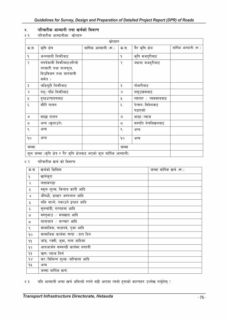
- 75 -
Guidelines for Survey, Design and Preparation of Detailed Project Report (DPR) of Roads
Transport Infrastructure Directorate, Hetauda
Guidelines for Survey Works Including Preparation of Detailed Project Report (DPR) of Roads
Transport Infrastructure Directorate, Hetauda
$= kl/jf/Ls cfDbfgL tyf vr{sf] ljj/0f $=! kl/jf/Ls cfDbfgLsf >|f]tx?
>|f]tx?
s|=;= s[lif If]q aflif{s cfDbfgL -¿=_ s|=;= u}/ s[lif If]` aflif{s cfDbfgL -¿=_
! cGgafnL laqmLaf6 ! s[lif dhb'/Ljf6
@ gub]afnL laqmLaf6-xl/of] t/sf/L tyf kmnkm'n, ljpljhg tyf afuafgL ;d]t _
@ Hofnf dhb'/Laf6
# hl8a'6L laqmLaf6 # gf]s/Laf6
$ kz'÷k+lIf laqmLaf6 $ n3'pBdaf6
% b'UwpTkfbgaf6 % Jofkf/ ÷ Joj;foaf6
^ Dff}/L kfng ^ k]G;g÷ljb]zjf6 k7fPsf]
& Dff5f kfng & ef8f÷Jofh
* cGo -v'nfpg]_ * ;Dklt a]rlavgaf6
( cGo ( cGo
!) cGo !) cGo
hDdf hDdf
s"n hDdf -s[lif If]q / u}/ s[lif If]`jf6 ePsf] s"n aflif{s cfDbfgL_
$=@ kl/jf/Ls vr{ sf] ljj/0f
s|=;= vr{sf] lsl;d hDdf jflif{s vr{ -¿=_
! vfg]s'/f
@ nQfsk8f
# :s'n z'Ns, lstfa sfkL cflb
$ cf}ifwL, 8fS6/ c:ktfn cflb
% alQ afNg], ksfpg] OGwg cflb
^ ;'grfFbL, u/uxgf cflb
& j:t'efp ÷ dnvfb cflb
* oftfoft ÷ ;~rf/ cflb
( ;fdflhs, rf8kj{, k'hf cflb
!) ;fdflhs sfo{df rGbf ÷bfg lbg
!! hfF8, /S;L, h'jf, tf; cflbdf
!@ cfocfh{g ;DaGwL sfo{df nufgL
!# C0f÷Jofh ltg{ !$ s/÷ljleGg z'Ns÷hl/jfgf cflb !% cGo hDdf aflif{s vr{M
$=# olb cfDbfgL eGbf vr{ cldNbf] ?kn] a9L cfPdf To;f] x'gfsf] sf/0fx? pNn]v ug{'xf];\ <
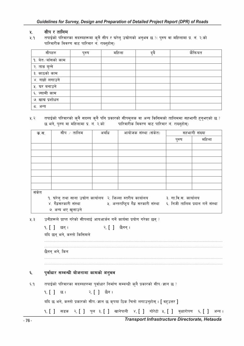
- 76 -
Guidelines for Survey, Design and Preparation of Detailed Project Report (DPR) of Roads
Transport Infrastructure Directorate, Hetauda
Guidelines for Survey Works Including Preparation of Detailed Project Report (DPR) of Roads
Transport Infrastructure Directorate, Hetauda
%= ;Lk / tflnd %=! tkfO{sf] kl/jf/sf ;b:ox¿df s"g} ;Lk / 3/]n' pBf]usf] cg'ej 5 <- k'?if jf dlxnfdf k|= g+= @=sf] kfl/jf/Ls ljj/0f jf6 kfl/jf/ g+= /fVg'xf];\_
;Lkx? k'?if dlxnf b'a} s}lkmot
!= a]t÷afF;sf] sfd
@= tfg| a'Gg]
#= sf7sf] sfd
$= ufx|f] nufpg]
%= 3/ agfpg]
^= HofdL sfd
&= vfB k|zf]wg
*= cGo
%=@ tkfO{sf] kl/jf/sf] s'g} ;b:o s'g} klg k|sf/sf] ;Lkd"ns jf cGo lsl;dsf] tflnddf ;xefuL x'g'ePsf] 5 <
5 eg], k'?if jf dlxnfdf k|= g+= @=sf] kfl/jf/Ls ljj/0f jf6 kfl/jf/ g+= /fVg'xf];\_
s|=;= ;Lk ÷ tflnd calw cfof]hs ;+:yf -;+s]t_ ;xefuL ;+Vof
k'?if dlxnf
;+s]t != 3/]n' tyf ;fgf pBf]u sfof{no @= lhNnf :t/Lo sfof{no #= uf=lj=;= sfof{no $= u}x|;/sf/L ;+:yf %= cGt/fli6«o u}x| ;/sf/L ;+:yf ^= lghL tflnd k|bfg ug]{ ;+:yf
&= cGo eP v'nfpg]
%=# pgLx¿n] k|fKt u/]sf] ;LknfO{ cfocfh{g ug]{ sfo{df k|of]u u/]sf 5g\ <
!, [ ] 5g\ . @, [ ] 5}gg\ .
olb 5g\ eg], s:tf] lsl;dn] ==================================================================================================================================================== ==================================================================================================================================================== 5}gg\ eg], lsg ==================================================================================================================================================== ====================================================================================================================================================
^= k'jf{wf/ ;DaGwL of]hgfdf sfdsf] cg'ej ^=! tkfO{sf] kl/jf/sf ;b:ox?df k"jf{wf/ lgdf{0f ;DaGwL s'g} k|sf/sf] ;Lk÷1fg 5 <
!, [ ] 5 . @, [ ] 5}g .
olb 5 eg], s:tf] k|sf/sf] ;Lk÷1fg 5 s[kof l7s lrgf] nufpg'xf];\ . [ jx'pQ/ ]
!, [ ] ;8s @, [ ] k'n #, [ ] vfg]kfgL $, [ ] uf]/]6f] %, [ ] j[Iff/f]k0f ^, [ ] cGo .
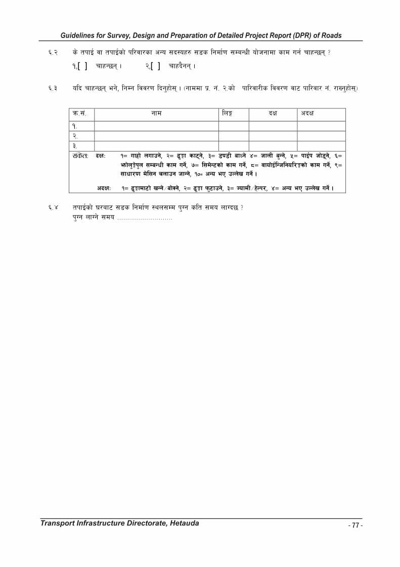
- 77 -
Guidelines for Survey, Design and Preparation of Detailed Project Report (DPR) of Roads
Transport Infrastructure Directorate, Hetauda
Guidelines for Survey Works Including Preparation of Detailed Project Report (DPR) of Roads
Transport Infrastructure Directorate, Hetauda
^=@ s] tkfO{ jf tkfO{sf] kl/jf/sf cGo ;b:ox? ;8s lgdf{0f ;DaGwL of]hgfdf sfd ug{ rfxG5g\ <
!,[ ] rfxG5g\ . @,[ ] rfxb}gg\ .
^=# olb rfxG5g\ eg], lgDg ljj/0f lbg'xf];\ . -gfddf k|= g+= @=sf] kfl/jf/Ls ljj/0f jf6 kfl/jf/ g+= /fVg'xf];\_
qm=;+= gfd lnË bIf cbIf
!= @= #= ;+s]tM bIfM !Ö ufx|f] nufpg], @Ö 9'∙f sf6\g], #Ö 808L afWg] $Ö hfnL a'Gg], %Ö kfO{k hf]8\g], ^Ö
emf]n'∙]k'n ;DaGwL sfd ug]{, &Ö l;d]G6sf] sfd ug]{, *Ö jfof]O{lGhlgol/∙sf] sfd ug]{, (Ö ;fwf/0f d]l;g rnfpg hfGg], !)≠ cGo eP pNn]v ug]{ .
cbIfM !Ö 9'∙fdf6f] vGg]÷af]Sg], @Ö 9'∙f km'6fpg], #Ö HofdL÷x]Nk/, $Ö cGo eP pNn]v ug]{ . ^=$ tkfO{sf] 3/af6 ;8s lgdf{0f :yn;Dd k'Ug slt ;do nfUb5 < k'Ug nfUg] ;do ============================
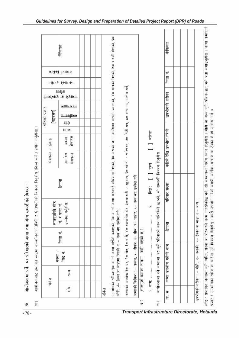
- 78 -
Guidelines for Survey, Design and Preparation of Detailed Project Report (DPR) of Roads
Transport Infrastructure Directorate, Hetauda
Gu
idelin
es f
or
Su
rvey
Wo
rks In
clu
din
g P
rep
ara
tio
n o
f D
eta
iled
Pro
ject
Rep
ort
(D
PR
) o
f R
oad
s
Tra
nsp
ort
In
frastr
uctu
re D
irecto
rate
, H
eta
ud
a
76
&=
cfo
f]hgf
df kg
]{ 3/
kl/j
f/sf] hUu
f ty
f cGo
;Dk
QLs
f] la
a/0f .
&=!
cfo
f]hgf
af6
k|eflj
t Nk
6df ;~r
flnt
ultl
awL /
v]lt
kftL
sf] laa/
0f lbg
'xf];\ -lgDg
;+s]t
k|of]u
ug{'x
f];\_ .
r]g]h
gS;f ÷
l;6
g+=
lsQf g+=
nfn
k'hf{s
f] df]7
g+= /
kfg
f g+=
pNn
]v u
g{'xf];
_ 7]u
fgf
If]qk
mn ÷
O{sfO{
Iflt
sf] k|s
f/
[jx'p
Q/]
sdfpg] jf pkef]usf] t/Lsf
hUufsf] pkof]u
hUufsf] lsl;d
s}lkmo
t
b]lv
;Dd
k|e
fljt
If]qk
mn
hDd
f If]qk
mn
hUuf
v]lt
¿vlj¿jf
;+/rgfx¿
;+s]t
pke
f]usf] t/
LsfM
!Ö c
fˆgf
] hUu
f cfFkm}n
] sdfPsf],
@Ö c
fˆgf
] hUu
f c¿nfO{ c
lwFof
df lbPs
f], #Ö
c¿sf] hUu
f clwFof
df cfkm'n
] sdfPsf],
$Ö a
GbsL lbPs
f]], %Ö
aGb
sL ln
Psf],
^Ö
df]xL,
&Ö 7
]Ssf jf e
f8fd
f lbPs
f] * Ö
cGo
eP
pNn
]v u
g]{,.
hUu
fsf] pko
f]uM !Ö
3/, @
Ö v
]t, #
Ö a
f/L,
$Ö Jof
kf/Ls I
f]q, %Ö
v/j
f/L ÷ a
'§ofg
, ^Ö
afFe
mf] ÷ r
l/r/g
, &Ö
lgh
L jg
, *Ö c
Go e
P pNn
]v u
g]{,
hUu
fsf] ls
l;dM !
Ö c
Aan, @Ö
bf]o
d, #
Ö ;
Ld, $Ö r
fxf/, %Ö
cGo
eP
pNn
]v u
g]{
&=@
,n
fnk'h
f{ s;sf gf
ddf h
f/L ePs
f] 5 <
!, gf
dM ===
======
======
======
======
======
======
======
======
====
@=
lnË
M [
] k
'?if
[
]
dlxnf
&=#
cfo
f]hgf
df kg
]{ hUu
fdf c?
s'g}
kl/j
f/n] s
fd u
l//x
]sf] 5 e
g], ;
f] ;Da
GwL lja/
0f lbg
'xf]; .
qm= ;+=
hUu
f pke
f]u u
g]{sf] gf
d
7]ufg
f kl/j
f/ ;
+Vof
slxn]] b
]lv p
kef]u
u/]s
f]] pke
f]usf] t/
Lsf
lsQf g+=
s}lkmo
t
pke
f]usf] t/
LsfM
!Ö d
f]xL],, @
Ö a
GbsL #
Ö 7
]Ssf jf e
f8f #
Ö c
Go .
-gf]6 M k
|eflj
t hUu
fdf s'g}
JolQ
m, ;+:y
f jf k
l/jf
/n] s
fd u
l//x
]sf]5
eg], ;
f] ;Da
Gwdf la
z]if
Wofg
lbg
'xf];\ . d
f]xL jf c
Go s
'g} >ld
s 5
g\ eg]
kQf nuf
pg'x
f];\ . h
Uuf sdfPsf]
k|sf/ /
pke
f]usf] tl
/sfs
f af
/]df k"0
f{ laa/
0f lbg
'xf];\ .
h:t
} pke
f]u u
/]sf] caw
L, clwFof
÷aG
bls j
f 7]S
sf s] x
f] pNn
]v u
g]{ ._
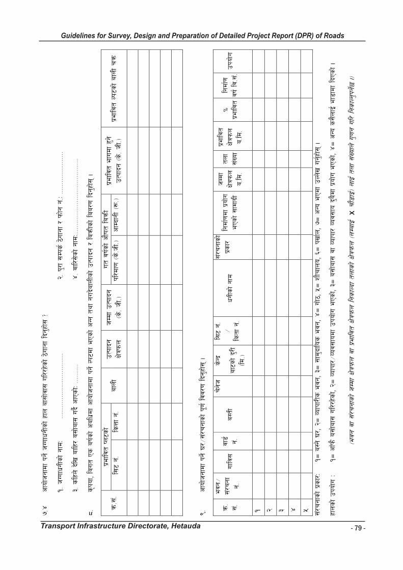
- 79 -
Guidelines for Survey, Design and Preparation of Detailed Project Report (DPR) of Roads
Transport Infrastructure Directorate, Hetauda
Gu
idelin
es f
or
Su
rvey
Wo
rks In
clu
din
g P
rep
ara
tio
n o
f D
eta
iled
Pro
ject
Rep
ort
(D
PR
) o
f R
oad
s
Tra
nsp
ort
In
frastr
uctu
re D
irecto
rate
, H
eta
ud
a
77
&=$
cfo
f]hgf
df kg
]{ hUu
fwgL
sf] xfn a
f;f]j
f; u
l//x
]sf] 7]u
fgf lbg'x
f]; <
!= h
Uufw
gLsf] gf
dM
====
======
======
======
======
======
@= k
'/f ;
Dks{ 7
]ufgf
/ k
mf]g g
+=M ===
======
======
======
=
#= s
lxn] b
]lv a
flx/
a;f]a
f; u
b}{ cfPsf]M
======
====
$= jf
l/;]sf] gf
dM=====
======
======
======
======
======
=====
*=
s[ko
f, la
ut P
s a
if{sf] calwd
f cfo
f]hgf
df kg
]{ Nk6
df ePs
f] cGg
tyf
gub
]afnLs
f] pTk
fbg
/ laqmLs
f] la
a/0f lbg
'xf];\ .
qm=;
+= k|e
fljt
Kn6s
f]
afnL
pTk
fbg
If]qk
mn
hDd
f pTk
fbg
-s
]= hL=_
ut j
if{sf] cf}if
t la
qmL
k|eflj
t efu
df x'g
] pTk
fbg
-s]= hL=_
k|e
fljt
Nk6s
f] af
nL rqm
l;
6 g+=
ls
Qf g+=
kl/d
f0f -s
]=hL=_
cfDbfgL
-¿=_
(=
cfo
f]hgf
df kg
]{ 3/÷
;+/r
gfsf] k"0
f{ ljj/
0f lbg
'xf];\ .
qm=
;+=
ejg
÷
;+/r
gf
g+=
uflj;
jf8{ g+=
a:tL
r]g]h
s]Gb
|
af6s
f] b'/
L
-ld=_
l;6
g+=
÷
lstf
g+=
wgLs
f] gf
d
;+/r
gfsf]
k|sf/
lgdf{0fd
f k|o
f]u
ePs
f] ;fd
fu|L
hDd
f If]qk
mn
a=ld
=
tnf
;+Vo
f
k|eflj
t If]qk
mn
a=ld
=
Ü
k|eflj
t lgdf{0f
jif{ lj=;
++= pko
f]u
!
@
#
$
%
;+/r
gfsf] k|s
f/M
!Ö a
:g] 3
/, @
Ö Jof
kf/Ls e
jg, #Ö
;fd
'bflos e
jg, $Ö u
f]7, %Ö
zf}r
fno, ^
Ö k
vf{n
, &Ö
cGo
ePd
f pNn
]v u
g{'xf];
\ .
xfnsf] pko
f]u M
!Ö
cfFkm} a;
f]af;
ul//x
]sf],
@Ö Jof
kf/÷
Joj;
fodf pko
f]u e
Psf],
#Ö a
;f]a
f; j
f Jo
fkf/ Joj
;fo
b'a}d
f k|o
f]u e
Psf],
$Ö c
Go s
;}nfO{ e
f8fd
f lbPs
f] .
-e
jg j
f ;+/
rgf
sf] hDd
f If]qk
mn j
f k|e
fljt
If]qk
mn lg
sfNb
f tn
fsf] If]qk
mn -nDa
fO{ x
rf}8
fO{_ nf
O{ tn
f ;+Vo
fn] u
'0fg u
l/ lgsfNg
'kg]{5
._

- 80 -
Guidelines for Survey, Design and Preparation of Detailed Project Report (DPR) of Roads
Transport Infrastructure Directorate, Hetauda
Guidelines for Survey Works Including Preparation of Detailed Project Report (DPR) of Roads
Transport Infrastructure Directorate, Hetauda
(=! olb 3/÷;+/rgf x6fpg' kg]{ 5 eg], s] of] ;+/rgf tkfO{sf] cfkm\g} hldgdf ag]sf] xf] <
!, [ ] xf] @, [ ] xf]O{g
olb xf]O{g eg], of] hldg s:sf] xf] gfd 7]ufgf atfO{lbg'xf];\ .
======================================================================================================================================
(=@ olb a;f]af; ul//x]sf] 3/ x6fpg' kg]{ ePdf, tkfO{ a;f]af; ug{sf] nflu of] afx]s s'g} csf]{ 3/ 5 <
!, [ ] 5 @, [ ] 5}g .
(=# olb 5 eg] sxfF 5 <
!, [ ] olx Nk6sf] csf]{ :yfgdf @, [ ] bf];|f] s'g} Nk6df .
(=$ olb of] 3/ cfof]hgfsf sf/0fn] eTsfpg' kg]{ ePdf csf]{ 3/df tkfO{sf] kl/jf/ j:g ;Sg] 7fpF pknAw 5 <
!, [ ] 5 @, [ ] 5}g .
(=% olb xfn al;/x]sf] Nk6b]lv km/s Nk6df hfg'kg]{ ePdf, ;f] Nk6 slt 6f9f 5 < ================ ls=ld= .
(=^ xfnsf] Nk6af6 goFf Nk6;Dd ;fdfg n}hfg s:tf] k|sf/sf] ;fwg k|of]u ug{'kb{5 <
!, [ ] k}bn @, [ ] a; #, [ ] l/S;f
$, [ ] 6«ofS6/ %, [ ] lghL s'g} ;jf/L ;fwg ^, [ ] cGo s'g} ==========
(=& gofF Nk6;Dd ;fdfg n}hfg cg'dflgt slt hlt vr{ nfUb5 < ================ ¿k}ofF .
(=* olb csf]{ 3/ 5}g eg], a;f]af;sf] Joj:yf s;/L ug{'x'G5 <
!, [ ] gofF 3/ agfP/ @, [ ] a;fO{ ;/L gofF 7fpFdf uP/
#, [ ] ef8fdf 3/ lnP/ $, [ ] cGo s'g} ;f]r ePdf ===================
Guidelines for Survey Works Including Preparation of Detailed Project Report (DPR) of Roads
Transport Infrastructure Directorate, Hetauda
(=( olb tkfO{n] of] 3/ ;8s cfof]hgfdf k/]kl5 gofF 3/ lsGg] jf agfpg] of]hgf agfpg' ePsf] 5 eg], o:t} k|sf/sf] 3/ agfpg slt hlt /sd vr{ xf]nf <
==================== ¿k}ofF .
(=!) ;8s cfof]hgfdf kg]{ of] 3/df tkfO{sf] afx]s cGo s'g} kl/jf/sf ;b:o klg a;f]af; ub{5g\ <
!, [ ] 5g\ @, [ ] 5}gg\ .
(=!! olb 5g\ eg], k"0f{ ljj/0f lbg'xf];\ .
3/ g+= kl/jf/d'nLsf] gfd 7]ufgf
Hfft÷ hflt
hDdf kl/jf/ ;+Vof
d"Vo k]zf
slt ;dob]lv a;f]af; ul//x]sf]
pkef]u u/]sf] sf]7f
;+Vof
ef8f k|lt dlxgf
a:g] lasNk
!)= cfof]hgfdf kg]{ Nk6af6 s'g} ?vlj?jf x6fpg' kb{5 .
!, [ ] k5{ . @, [ ] kb}{g .
!)=! cfof]hgfdf kg]{ Nk6jf6 s'g} ¿vlj¿jf x6fpg' kg]{ ePdf lgDgfg';f/sf] ljj/0f lbg'xf];\ .
r]g]h gfd÷hft k|sf/ uf]nfO{ -;]dL_ prfO{ -ld=_ ;+Vof s}lkmot
b]lv ;Dd
;+s]tM k|sf/M !Ö sf7sf nflu k|of]u x'g] ¿v, @ Öbfp/fsf] nflu k|of]u x'g] ¿v, # Öax' k|of]usf] ¿v, , $Ö u}x| sfi7 jg k}bfj/, %Ö cGo eP pNn]v ug]{ ==========
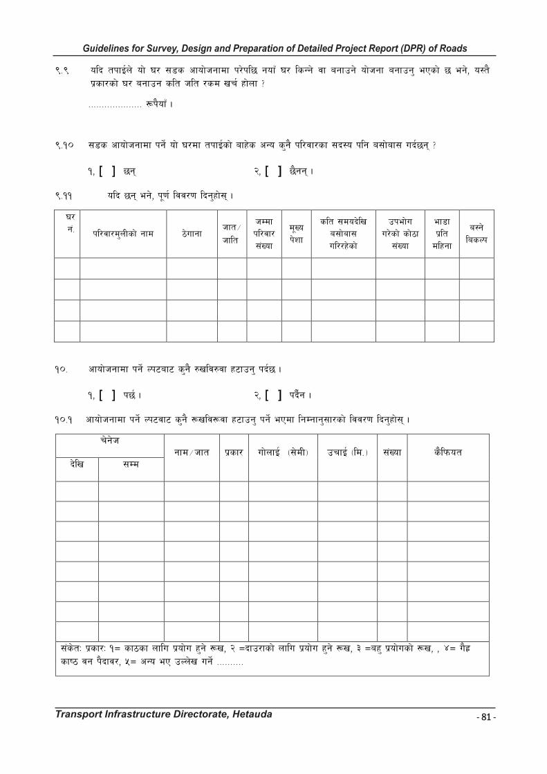
- 81 -
Guidelines for Survey, Design and Preparation of Detailed Project Report (DPR) of Roads
Transport Infrastructure Directorate, Hetauda
Guidelines for Survey Works Including Preparation of Detailed Project Report (DPR) of Roads
Transport Infrastructure Directorate, Hetauda
(=( olb tkfO{n] of] 3/ ;8s cfof]hgfdf k/]kl5 gofF 3/ lsGg] jf agfpg] of]hgf agfpg' ePsf] 5 eg], o:t} k|sf/sf] 3/ agfpg slt hlt /sd vr{ xf]nf <
==================== ¿k}ofF .
(=!) ;8s cfof]hgfdf kg]{ of] 3/df tkfO{sf] afx]s cGo s'g} kl/jf/sf ;b:o klg a;f]af; ub{5g\ <
!, [ ] 5g\ @, [ ] 5}gg\ .
(=!! olb 5g\ eg], k"0f{ ljj/0f lbg'xf];\ .
3/ g+= kl/jf/d'nLsf] gfd 7]ufgf
Hfft÷ hflt
hDdf kl/jf/ ;+Vof
d"Vo k]zf
slt ;dob]lv a;f]af; ul//x]sf]
pkef]u u/]sf] sf]7f
;+Vof
ef8f k|lt dlxgf
a:g] lasNk
!)= cfof]hgfdf kg]{ Nk6af6 s'g} ?vlj?jf x6fpg' kb{5 .
!, [ ] k5{ . @, [ ] kb}{g .
!)=! cfof]hgfdf kg]{ Nk6jf6 s'g} ¿vlj¿jf x6fpg' kg]{ ePdf lgDgfg';f/sf] ljj/0f lbg'xf];\ .
r]g]h gfd÷hft k|sf/ uf]nfO{ -;]dL_ prfO{ -ld=_ ;+Vof s}lkmot
b]lv ;Dd
;+s]tM k|sf/M !Ö sf7sf nflu k|of]u x'g] ¿v, @ Öbfp/fsf] nflu k|of]u x'g] ¿v, # Öax' k|of]usf] ¿v, , $Ö u}x| sfi7 jg k}bfj/, %Ö cGo eP pNn]v ug]{ ==========
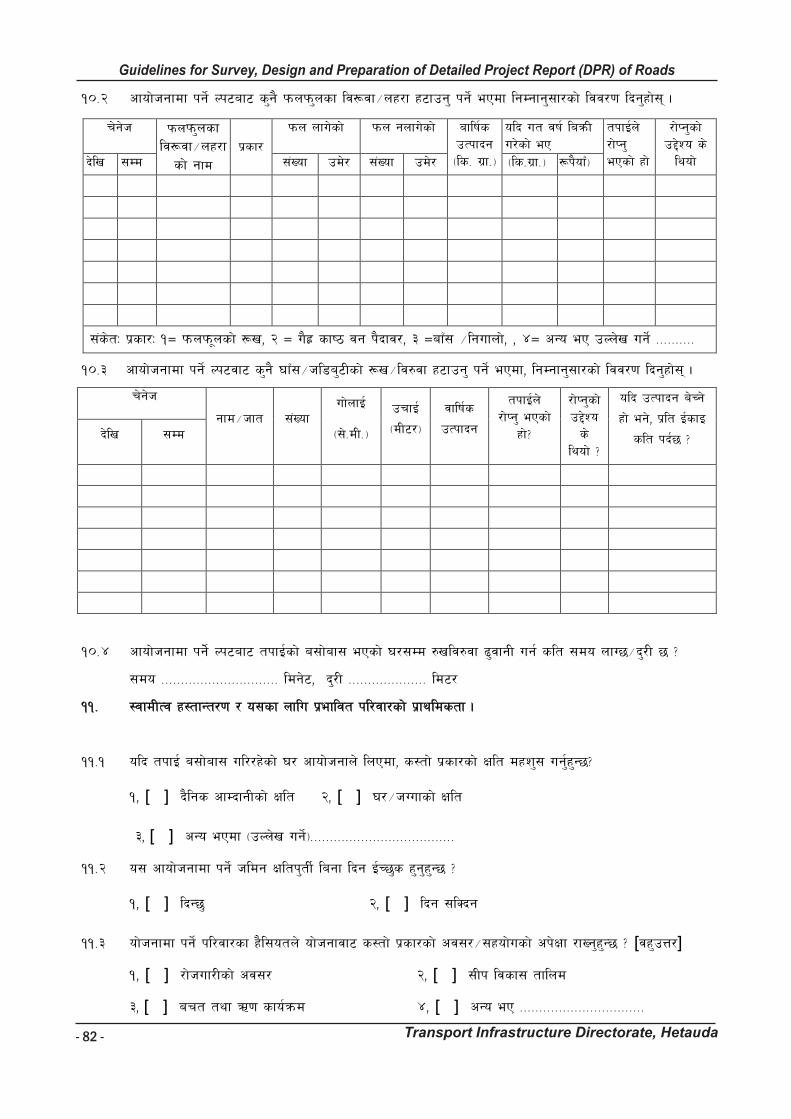
- 82 -
Guidelines for Survey, Design and Preparation of Detailed Project Report (DPR) of Roads
Transport Infrastructure Directorate, Hetauda
Guidelines for Survey Works Including Preparation of Detailed Project Report (DPR) of Roads
Transport Infrastructure Directorate, Hetauda
!)=@ cfof]hgfdf kg]{ Nk6af6 s'g} kmnkm'nsf lj¿jf÷nx/f x6fpg' kg]{ ePdf lgDgfg';f/sf] ljj/0f lbg'xf];\ .
r]g]h kmnkm'nsf lj¿jf÷nx/f
sf] gfd k|sf/
kmn nfu]sf] kmn gnfu]sf] aflif{s pTkfbg -ls= u|f=_
olb ut jif{ laqmL u/]sf] eP
tkfO{n] /f]Kg' ePsf] xf]
/f]Kg'sf] p2]Zo s] lyof] b]lv ;Dd ;+Vof pd]/ ;+Vof pd]/ -ls=u|f=_ -¿k}ofF_
;+s]tM k|sf/M !Ö kmnkm"nsf] ¿v, @ Ö u}x| sfi7 jg k}bfj/, # ÖafF; ÷lgufnf], , $Ö cGo eP pNn]v ug]{ ==========
!)=# cfof]hgfdf kg]{ Nk6jf6 s'g} 3fF;÷hl8a'6Lsf] ¿v÷lj?jf x6fpg' kg]{ ePdf, lgDgfg';f/sf] ljj/0f lbg'xf];\ .
r]g]h
gfd÷hft ;+Vof uf]nfO{
-;]=dL=_
prfO{
-dL6/_
jflif{s
pTkfbg
tkfO{n] /f]Kg' ePsf]
xf]<
/f]Kg'sf] p2]Zo s]
lyof] <
olb pTkfbg a]Rg]
xf] eg], k|lt O{sfO
slt kb{5 < b]lv ;Dd
!)=$ cfof]hgfdf kg]]{ Nk6af6 tkfO{sf] a;f]af; ePsf] 3/;Dd ?vlj?jf 9'jfgL ug{ slt ;do nfU5÷b'/L 5 <
;do ============================== ldg]6, b'/L ==================== ld6/
!!= :jfdLTj x:tfGt/0f / o;sf nflu k|efljt kl/jf/sf] k|fyldstf .
!!=! olb tkfO{ a;f]af; ul//x]sf] 3/ cfof]hgfn] lnPdf, s:tf] k|sf/sf] Iflt dxz'; ug{'x'G5<
!, [ ] b}lgs cfDbfgLsf] Iflt @, [ ] 3/÷hUufsf] Iflt
#, [ ] cGo ePdf -pNn]v ug]{_=====================================
!!=@ o; cfof]hgfdf kg]{ hldg Ifltk'tL{ lagf lbg O{R5's x'g'x'G5 <
!, [ ] lbG5' @, [ ] lbg ;lSbg
!!=# of]hgfdf kg]{ kl/jf/sf x}l;otn] of]hgfjf6 s:tf] k|sf/sf] cj;/÷;xof]usf] ck]Iff /fVg'x'G5 < [jx'pQ/]
!, [ ] /f]huf/Lsf] cj;/ @, [ ] ;Lk ljsf; tflnd
#, [ ] art tyf C0f sfo{qmd $, [ ] cGo eP ================================
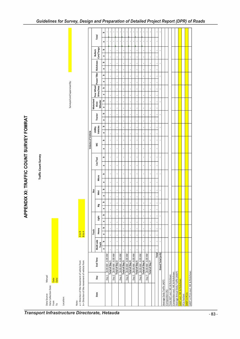
- 83 -
Guidelines for Survey, Design and Preparation of Detailed Project Report (DPR) of Roads
Transport Infrastructure Directorate, Hetauda
Gu
ide
lin
es
fo
r S
urv
ey
Wo
rks I
nc
lud
ing
Pre
pa
rati
on
of
De
tail
ed
Pro
jec
t R
ep
ort
(D
PR
) o
f R
oa
ds
Tra
ns
po
rt I
nfr
as
tru
ctu
re D
irec
tora
te,
He
tau
da
81
AP
PE
ND
IX X
I: T
RA
FF
IC C
OU
NT
SU
RV
EY
FO
MR
AT
Dat
a So
urce
:
Dat
a C
olle
ctio
n D
ate
Fro
m
To Loca
tio
n:
ab
ab
ab
ab
ab
ab
ab
ab
ab
ab
ab
ab
ab
ab
ab
ab
Day
16:
00 A
M -
6:0
0 A
M-
-
- -
- -
- -
- -
- -
-
-
-
-
-
-
- -
- -
- -
- -
- -
- -
- -
-
-
Day
26:
00 A
M -
6:0
0 A
M-
-
- -
- -
- -
- -
- -
-
-
-
-
-
-
- -
- -
- -
- -
- -
- -
- -
-
-
Day
36:
00 A
M -
6:0
0 A
M-
-
- -
- -
- -
- -
- -
-
-
-
-
-
-
- -
- -
- -
- -
- -
- -
- -
-
-
Day
46:
00 A
M -
6:0
0 A
M-
-
- -
- -
- -
- -
- -
-
-
-
-
-
-
- -
- -
- -
- -
- -
- -
- -
-
-
Day
56:
00 A
M -
6:0
0 A
M-
-
- -
- -
- -
- -
- -
-
-
-
-
-
-
- -
- -
- -
- -
- -
- -
- -
-
-
Day
66:
00 A
M -
6:0
0 A
M-
-
- -
- -
- -
- -
- -
-
-
-
-
-
-
- -
- -
- -
- -
- -
- -
- -
-
-
Day
76:
00 A
M -
6:0
0 A
M-
-
- -
- -
- -
- -
- -
-
-
-
-
-
-
- -
- -
- -
- -
- -
- -
- -
-
-
- -
- -
- -
- -
- -
-
-
-
-
-
-
- -
- -
- -
- -
- -
- -
- -
-
-
Traf
fic
Coun
t Su
rvey
AA
DT
in P
CU
s ex
cl. M
C &
Ric
ksha
ws
AA
DT
in P
CU
s
PCU
Fac
tors
AA
DT
excl
. MC
& R
icks
haw
s
Ave
rage
Ann
ual D
aily
Tra
ffic
(AA
DT)
Co
mpo
siti
on
excl
. MC
& R
icks
haw
s
Tota
l AD
T ex
cl. M
C &
Ric
ksha
ws
Co
mpo
siti
on
(%)
Ave
rage
Dai
ly T
raff
ic (A
DT)
-
-
-
B t
o A
A t
o B
-
-
-
-
-
-
-
-
-
-
-
-
Ric
ksh
aws
Tota
l of
Day
3
Tota
l
Gra
nd
To
tal (
a+b
)-
Tota
l of
Day
1
Tota
l of
Day
2
Tota
l of
Day
4
Tota
l of
Day
5
Tota
l of
Day
6
Tota
l of
Day
7
Mu
lti-
axle
Tru
ckH
eavy
Ligh
tB
igM
ini
Bu
llock
Car
t/Ta
nga
Tota
lD
ate
Day
End
Tim
e
Vo
lum
e o
f V
ehic
le
Tru
ckB
us
Car
/Tax
iM
CU
tilli
ty
Veh
icle
sTr
acto
rM
icro
Mo
tori
sed
thre
e
Wh
eele
r
Fou
r W
hee
l
Dri
ve/J
eep
Po
wer
Till
er
Man
ual
Dat
e
Dat
e
b =
Dir
ecti
on
of
the
mo
vem
ent
of
vehi
cle
fro
m
No
te:
a =
Dir
ecti
on
of
the
mo
vem
ent
of
vehi
cle
fro
m
Surv
eyed
and
Sup
ervi
sed
By:
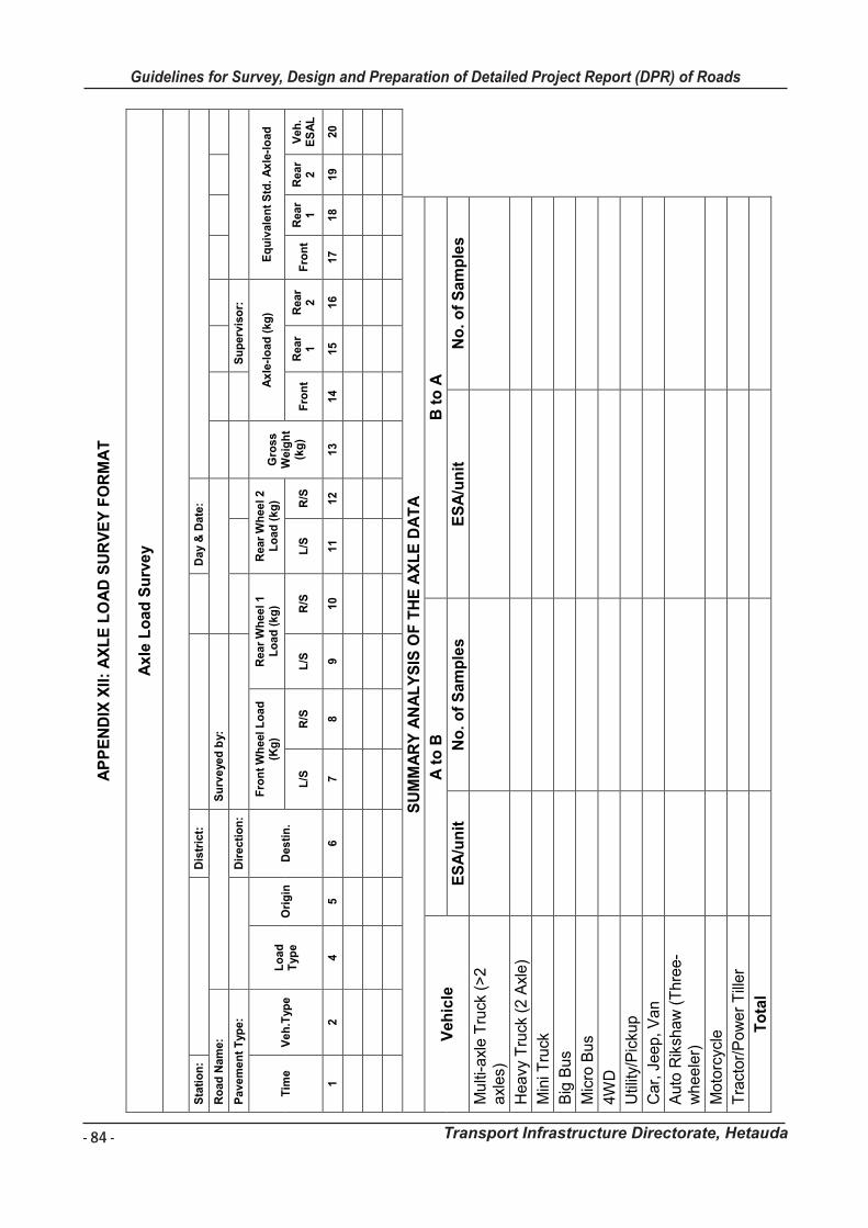
- 84 -
Guidelines for Survey, Design and Preparation of Detailed Project Report (DPR) of Roads
Transport Infrastructure Directorate, Hetauda
Gu
idelin
es f
or
Su
rvey
Wo
rks In
clu
din
g P
rep
ara
tio
n o
f D
eta
iled
Pro
ject
Rep
ort
(D
PR
) o
f R
oad
s
Tra
nsp
ort
In
frastr
uctu
re D
irecto
rate
, H
eta
ud
a
82
AP
PE
ND
IX X
II:
AX
LE
LO
AD
SU
RV
EY
FO
RM
AT
Ax
le L
oad
Su
rve
y
S
tati
on
:
D
istr
ict:
D
ay &
Date
:
Ro
ad
Nam
e:
S
urv
eye
d b
y:
P
avem
en
t T
ype:
D
irecti
on
:
S
up
erv
iso
r:
Tim
e
Veh
.Typ
e
Lo
ad
T
yp
e
Ori
gin
D
esti
n.
Fro
nt
Wh
eel L
oad
(K
g)
Rear
Wh
eel 1
Lo
ad
(kg
) R
ear
Wh
eel 2
Lo
ad
(kg
) G
ross
Weig
ht
(kg
)
Ax
le-l
oad
(kg
) E
qu
ivale
nt
Std
. A
xle
-lo
ad
L/S
R
/S
L/S
R
/S
L/S
R
/S
Fro
nt
R
ear
1
Rear
2
Fro
nt
Rear
1
Rear
2
Veh
. E
SA
L
1
2
4
5
6
7
8
9
10
11
12
13
14
15
16
17
18
19
20
SU
MM
AR
Y A
NA
LY
SIS
OF
TH
E A
XL
E D
AT
A
Veh
icle
A
to
B
B t
o A
ES
A/u
nit
N
o.
of
Sam
ple
s
ES
A/u
nit
N
o.
of
Sam
ple
s
Mu
lti-a
xle T
ruck
(>
2
axl
es)
Heavy
Tru
ck (
2 A
xle)
Min
i Tru
ck
Big
Bus
Mic
ro B
us
4W
D
Util
ity/P
icku
p
Car,
Jeep, V
an
Auto
Rik
shaw
(T
hre
e-
whee
ler)
Moto
rcyc
le
Tra
ctor/
Pow
er
Till
er
To
tal

- 85 -
Guidelines for Survey, Design and Preparation of Detailed Project Report (DPR) of Roads
Transport Infrastructure Directorate, Hetauda
Gu
idelin
es f
or
Su
rvey
Wo
rks In
clu
din
g P
rep
ara
tio
n o
f D
eta
iled
Pro
ject
Rep
ort
(D
PR
) o
f R
oad
s
Tra
nsp
ort
In
frastr
uctu
re D
irecto
rate
, H
eta
ud
a
83
AP
PE
ND
IX X
III:
MA
TE
RIA
L A
VA
ILA
BIL
ITY
SU
RV
EY
FO
RM
AT
Lo
cati
on
/ C
hain
ag
e
Dis
tan
ce f
rom
th
e R
oad
Sid
e o
f th
e
Ro
ad
(L
eft
/Rig
ht.
)
Typ
e o
f m
ate
rial
avail
ab
le in
th
e
qu
arr
y
(San
d/G
ravel/
Sto
nes)
Sta
tus o
f th
e a
ccess
road
A
pp
roxim
ate
qu
an
tity
of
mate
rial avail
ab
le
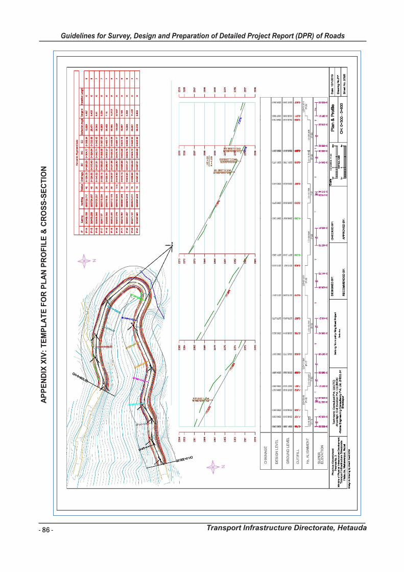
- 86 -
Guidelines for Survey, Design and Preparation of Detailed Project Report (DPR) of Roads
Transport Infrastructure Directorate, Hetauda
Gui
delin
es fo
r Sur
vey
Wor
ks In
clud
ing
Prep
arat
ion
of D
etai
led
Proj
ect R
epor
t (D
PR) o
f Roa
ds
Tran
spor
t Inf
rast
ruct
ure
Dire
ctor
ate,
Het
auda
87
APPE
ND
IX X
IV:T
EMPL
ATE
FOR
PLA
N P
RO
FILE
& C
RO
SS-S
ECTI
ON
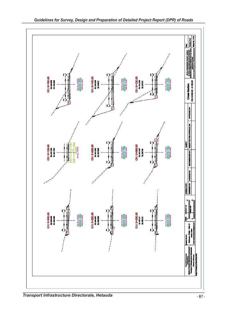
- 87 -
Guidelines for Survey, Design and Preparation of Detailed Project Report (DPR) of Roads
Transport Infrastructure Directorate, HetaudaGui
delin
es fo
r Sur
vey
Wor
ks In
clud
ing
Prep
arat
ion
of D
etai
led
Proj
ect R
epor
t (D
PR) o
f Roa
ds
Tran
spor
t Inf
rast
ruct
ure
Dire
ctor
ate,
Het
auda
88
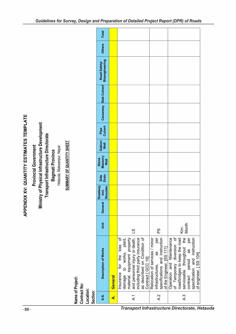
- 88 -
Guidelines for Survey, Design and Preparation of Detailed Project Report (DPR) of Roads
Transport Infrastructure Directorate, Hetauda
Gu
ide
lin
es
fo
r S
urv
ey
Wo
rks I
nc
lud
ing
Pre
pa
rati
on
of
De
tail
ed
Pro
jec
t R
ep
ort
(D
PR
) o
f R
oa
ds
Tra
ns
po
rt I
nfr
as
tru
ctu
re D
irec
tora
te,
He
tau
da
86
AP
PE
ND
IX X
V:
QU
AN
TIT
Y E
ST
IMA
TE
S T
EM
PL
AT
E
Pro
vinc
ial G
over
nmen
t
Min
istr
y of
Phy
sica
l Inf
rast
ruct
ure
Dev
elop
men
t
Tran
spor
t Inf
rast
ruct
ure
Dir
ecto
rate
Bag
mat
i Pro
vinc
e H
etau
da, M
akw
anpu
r, N
epal
SU
MM
AR
Y O
F Q
UA
NTI
TY S
HE
ET
Nam
e of
Pro
ject
:
Con
trac
t No:
Loca
tion:
Sec
tion:
S.N
. D
escri
pti
on
of
Wo
rks
Un
it
Gen
era
l R
oad
wa
y in
cl.
Sh
ou
lder
Sid
e
Dra
in
Sto
ne
Maso
nry
W
all
Gab
ion
W
all
Pip
e
Cu
lvert
C
au
sew
ay
Sla
b C
ulv
ert
R
oad
Safe
ty/
Bio
en
gin
eeri
ng
O
thers
T
ota
l
A.
Ge
ne
ral
A.1
Insu
ran
ce
for
the
lo
ss
of
da
ma
ge
to
w
ork
s,
pla
nt,
ma
terial,
eq
uip
me
nt
pro
pe
rty
an
d p
ers
on
ne
l in
jury
or
de
ath
, in
clu
din
g t
hird
pa
rty
insu
ran
ce
as
de
scrib
ed o
n C
on
diti
on
of
Co
ntr
act
[ G
CC
19
]
LS
A.2
Re
loca
tion
of
serv
ice
s /
min
or
infr
ast
ruct
ure
s,
as
pe
r sp
eci
fica
tion
s a
nd
in
stru
ctio
n
of
the
En
gin
ee
r. [S
S 1
11
]
PS
A.3
Op
era
tion
a
nd
M
ain
ten
an
ce
of
Tem
po
rary
d
ive
rsio
n
of
roa
d/b
ridg
es
to k
ee
p t
he
ro
ad
se
rvic
ea
ble
th
rou
gh
ou
t th
e
con
tra
ct
pe
riod
a
s p
er
spe
cific
atio
n
an
d
inst
ruct
ion
of
en
gin
ee
r. [
SS
10
4]
Km
-M
on
th
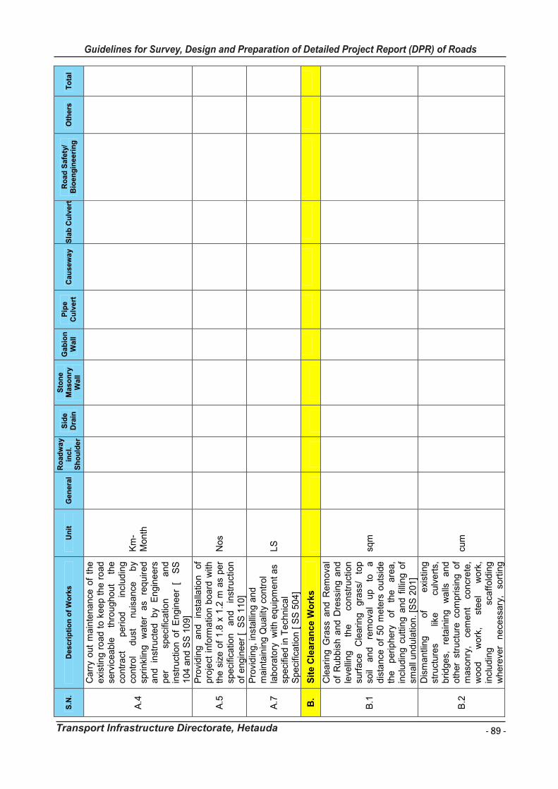
- 89 -
Guidelines for Survey, Design and Preparation of Detailed Project Report (DPR) of Roads
Transport Infrastructure Directorate, Hetauda
Gu
ide
lin
es
fo
r S
urv
ey
Wo
rks I
nc
lud
ing
Pre
pa
rati
on
of
De
tail
ed
Pro
jec
t R
ep
ort
(D
PR
) o
f R
oa
ds
Tra
ns
po
rt I
nfr
as
tru
ctu
re D
irec
tora
te,
He
tau
da
87
S.N
. D
escri
pti
on
of
Wo
rks
Un
it
Gen
era
l R
oad
wa
y in
cl.
Sh
ou
lder
Sid
e
Dra
in
Sto
ne
Maso
nry
W
all
Gab
ion
W
all
Pip
e
Cu
lvert
C
au
sew
ay
Sla
b C
ulv
ert
R
oad
Safe
ty/
Bio
en
gin
eeri
ng
O
thers
T
ota
l
A.4
Ca
rry
ou
t m
ain
ten
an
ce o
f th
e
exi
stin
g r
oa
d t
o k
ee
p t
he
ro
ad
se
rvic
ea
ble
th
rou
gh
ou
t th
e
con
tra
ct
pe
riod
in
clu
din
g
con
tro
l d
ust
n
uis
an
ce
by
spri
nklin
g
wa
ter
as
req
uir
ed
a
nd
in
stru
cte
d
by
En
gin
ee
rs
pe
r sp
eci
fica
tion
a
nd
in
stru
ctio
n o
f E
ng
ine
er
[ S
S
10
4 a
nd
SS
10
9]
Km
-M
on
th
A.5
Pro
vid
ing
a
nd
in
sta
llatio
n
of
pro
ject
in
form
atio
n b
oa
rd w
ith
the
siz
e o
f 1
.8 x
1.2
m a
s p
er
spe
cific
atio
n
an
d
inst
ruct
ion
o
f e
ngin
ee
r [
SS
11
0]
No
s
A.7
Pro
vid
ing
, in
sta
llin
g a
nd
m
ain
tain
ing
Qu
alit
y co
ntr
ol
lab
ora
tory
w
ith e
qu
ipm
en
t a
s sp
eci
fied
in T
ech
nic
al
Spe
cific
atio
n [ S
S 5
04
]
LS
B.
Sit
e C
lea
ran
ce
Wo
rks
B.1
Cle
ari
ng
Gra
ss a
nd
Re
mo
val
of
Ru
bb
ish
an
d D
ress
ing
an
d
leve
llin
g
the
co
nst
ruct
ion
su
rfa
ce
Cle
arin
g
gra
ss/
top
so
il a
nd
re
mo
val
up
to
a
d
ista
nce
of
50
me
ters
ou
tsid
e
the
p
erip
he
ry
of
the
a
rea
, in
clu
din
g c
utt
ing
an
d f
illin
g o
f sm
all
un
du
latio
n.
[SS
20
1]
sqm
B.2
Dis
ma
ntli
ng
o
f e
xist
ing
st
ruct
ure
s lik
e
culv
ert
s,
brid
ge
s,
reta
inin
g
wa
lls
an
d
oth
er
stru
ctu
re co
mp
risi
ng
o
f m
aso
nry
, ce
me
nt
con
cre
te,
wo
od
w
ork
, st
ee
l w
ork
, in
clu
din
g
sca
ffo
ldin
g
wh
ere
ver
ne
cess
ary
, so
rtin
g
cum
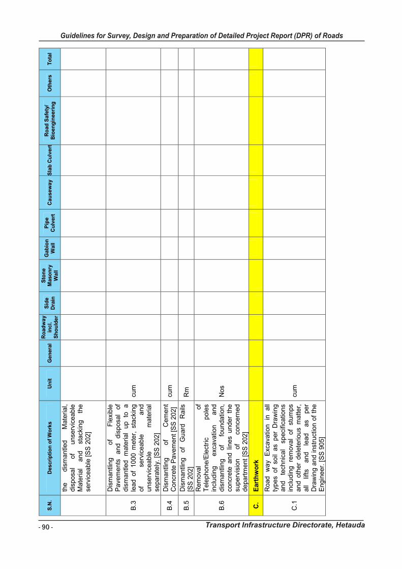
- 90 -
Guidelines for Survey, Design and Preparation of Detailed Project Report (DPR) of Roads
Transport Infrastructure Directorate, Hetauda
Gu
idelin
es f
or
Su
rvey
Wo
rks In
clu
din
g P
rep
ara
tio
n o
f D
eta
iled
Pro
ject
Rep
ort
(D
PR
) o
f R
oad
s
Tra
nsp
ort
In
frastr
uctu
re D
irecto
rate
, H
eta
ud
a
88
S.N
. D
es
cri
pti
on
of
Wo
rks
Un
it
Ge
nera
l R
oad
wa
y in
cl.
Sh
ou
lde
r
Sid
e
Dra
in
Sto
ne
M
aso
nry
W
all
Ga
bio
n
Wa
ll
Pip
e
Cu
lve
rt
Cau
se
wa
y
Sla
b C
ulv
ert
R
oad
Sa
fety
/ B
ioe
ng
ine
eri
ng
O
thers
T
ota
l
the
dis
mantle
d
Mate
rial,
dis
posa
l of
unse
rvic
ea
ble
M
ate
rial
an
d
stack
ing
the
serv
icea
ble
[S
S 2
02]
B.3
Dis
mantli
ng
of
Fle
xible
P
ave
ments
and
d
isposa
l of
dis
mantle
d
mate
rial
up
to
a
lea
d o
f 10
00 m
ete
r, s
tack
ing
of
serv
iceable
a
nd
unse
rvic
eab
le
mate
rial
separa
tely
. [S
S 2
02
]
cum
B.4
D
ism
antli
ng
of
Cem
ent
Concr
ete
Pave
ment [S
S 2
02]
cum
B.5
D
ism
antli
ng
of
Gu
ard
R
ails
[S
S 2
02]
Rm
B.6
Rem
ova
l of
Tele
phone/E
lect
ric
po
les
incl
udin
g
exc
ava
tion
and
dis
mantli
ng
of
foundatio
n,
concr
ete
an
d l
ines
und
er
the
superv
isio
n
of
conce
rned
depart
ment [S
S 2
02]
Nos
C.
Eart
hw
ork
C.1
Road
wa
y E
xcava
tion
in
all
typ
es
of
soil
as
per
Dra
win
g
and
te
chnic
al
speci
ficatio
ns
incl
udin
g
rem
ova
l of
stum
ps
and o
ther
de
lete
rio
us
matter,
all
lifts
and
le
ad
as
per
Dra
win
g a
nd
inst
ruct
ion
of
the
Eng
ineer.
[S
S 9
05
]
cum

- 91 -
Guidelines for Survey, Design and Preparation of Detailed Project Report (DPR) of Roads
Transport Infrastructure Directorate, Hetauda
Gu
idelin
es f
or
Su
rvey
Wo
rks In
clu
din
g P
rep
ara
tio
n o
f D
eta
iled
Pro
ject
Rep
ort
(D
PR
) o
f R
oad
s
Tra
nsp
ort
In
frastr
uctu
re D
irecto
rate
, H
eta
ud
a
89
S.N
. D
es
cri
pti
on
of
Wo
rks
Un
it
Ge
nera
l R
oad
wa
y in
cl.
Sh
ou
lde
r
Sid
e
Dra
in
Sto
ne
M
aso
nry
W
all
Ga
bio
n
Wa
ll
Pip
e
Cu
lve
rt
Cau
se
wa
y
Sla
b C
ulv
ert
R
oad
Sa
fety
/ B
ioe
ng
ine
eri
ng
O
thers
T
ota
l
C.2
Pro
vid
ing
, la
ying,
spre
ad
ing
and c
om
pact
ing e
mbankm
ent
with
su
itab
le
mate
rial
and
com
pact
to
th
e
req
uir
ed
densi
ty
as
per
Dra
win
g
and
Tech
nic
al
Speci
ficatio
ns.
[S
S
909,9
10]
cum
S
UB
TO
TA
L
D.
Pav
em
en
t W
ork
s
D.1
Pro
vid
ing
an
d
layi
ng
sub-
gra
de a
nd e
art
hen s
hould
ers
w
ith
appro
ved
Mate
rial
(incl
udin
g
Ca
pp
ing
La
yer)
obta
ine
d f
rom
borr
ow
pits
with
all
lifts
&
le
ads
as
per
Dra
win
g
an
d
Tech
nic
al
Speci
ficatio
ns.
[S
S 1
004
]
sqm
D.2
Pro
vid
ing
an
d
layi
ng
sub-
gra
de a
nd e
art
hen s
hould
ers
w
ith
appro
ved
Mate
rial
obta
ine
d f
rom
borr
ow
pits
with
all
lifts
&
le
ads
as
per
Dra
win
g
an
d
Tech
nic
al
Speci
ficatio
ns.
[S
S 1
003
]
sqm
D.3
Pro
vid
ing
an
d l
ayi
ng g
ranu
lar
sub
-base
on
pre
pare
d
surf
ace
, m
ixin
g a
t O
MC
, a
nd
com
pact
ing
to
ach
ieve
th
e
desi
red densi
ty,
com
ple
te as
per
Dra
win
g
and
T
ech
nic
al
Speci
ficatio
ns.
, [S
S 1
20
1]
cum
D.3
Pro
vid
ing
, la
ying,
spre
ad
ing
and c
om
pact
ing W
ate
r bou
nd
maca
dam
in
clud
ing
b
oom
ing
requis
ite
type
of
scre
enin
g/b
ind
ing
mate
rials
to
fill up t
he inte
rstic
es
of
coars
e
cum

- 92 -
Guidelines for Survey, Design and Preparation of Detailed Project Report (DPR) of Roads
Transport Infrastructure Directorate, Hetauda
Gu
idelin
es f
or
Su
rvey
Wo
rks In
clu
din
g P
rep
ara
tio
n o
f D
eta
iled
Pro
ject
Rep
ort
(D
PR
) o
f R
oad
s
Tra
nsp
ort
In
frastr
uctu
re D
irecto
rate
, H
eta
ud
a
90
S.N
. D
escri
pti
on
of
Wo
rks
Un
it
Gen
era
l R
oad
wa
y in
cl.
Sh
ou
lder
Sid
e
Dra
in
Sto
ne
Maso
nry
W
all
Gab
ion
W
all
Pip
e
Cu
lvert
C
au
sew
ay
Sla
b C
ulv
ert
R
oad
Safe
ty/
Bio
en
gin
eeri
ng
O
thers
T
ota
l
aggre
gate
, w
ate
ring
and
com
pact
ing
the
req
uir
ed
densi
ty
as
per
Dra
win
g
and
Tech
nic
al
Speci
ficatio
ns;
[S
S
1203]
D.4
Pro
vid
ing
an
d l
ayi
ng C
rusher
Run M
aca
dam
on a
pre
pare
d
surf
ace
, sp
readin
g
and
mix
ing,
wate
rin
g
and
com
pact
ing
to f
orm
a l
aye
r of
Base
co
urs
e a
s p
er
Dra
win
g
and
Tech
nic
al
Speci
ficatio
ns.
, [S
S 1
204]
cum
D.5
Pro
vid
ing a
nd a
pp
lyin
g p
rim
e
coat
with
H
ot
Bitu
men
(incl
udin
g c
utter)
on p
repare
d
surf
ace
of
gra
nula
r b
ase
in
clu
din
g
cle
an
ing
of
road
surf
ace
and
spra
ying
b
y m
ech
anic
al
means
as
per
Tech
nic
al
Specifi
catio
n.
[SS
1302]
lit
D.6
Pro
vid
ing
an
d
app
lyin
g
tack
co
at
with
H
ot
Bitu
men
at
speci
fied r
ate
on t
he p
repare
d
non-b
itum
inous
surf
ace
in
clu
din
g
clean
ing
as
per
Tech
nic
al
Speci
ficatio
n
[SS
1302]
lit
D.7
Surf
ace
D
ress
ing
, P
rovi
din
g
and
layi
ng
surf
ace
dre
ssin
g
as
we
arin
g
cours
e
in
sin
gle
co
at
usi
ng g
rave
l of
speci
fied
size
o
n
a
rece
ntly
ap
plie
d
laye
r of
bitu
min
ous
bin
der
on
pre
pare
d
surf
ace
as
per
Dra
win
g
an
d
Tech
nic
al
sqm

- 93 -
Guidelines for Survey, Design and Preparation of Detailed Project Report (DPR) of Roads
Transport Infrastructure Directorate, Hetauda
Gu
idelin
es f
or
Su
rvey
Wo
rks In
clu
din
g P
rep
ara
tio
n o
f D
eta
iled
Pro
ject
Rep
ort
(D
PR
) o
f R
oad
s
Tra
nsp
ort
In
frastr
uctu
re D
irecto
rate
, H
eta
ud
a
91
S.N
. D
escri
pti
on
of
Wo
rks
Un
it
Gen
era
l R
oad
wa
y in
cl.
Sh
ou
lder
Sid
e
Dra
in
Sto
ne
Maso
nry
W
all
Gab
ion
W
all
Pip
e
Cu
lvert
C
au
sew
ay
Sla
b C
ulv
ert
R
oad
Safe
ty/
Bio
en
gin
eeri
ng
O
thers
T
ota
l
Speci
ficatio
ns.
, 19
mm
nom
inal
chip
pin
g
size
[S
S
1303]
D.8
Surf
ace
D
ress
ing
, P
rovi
din
g
and
layi
ng
surf
ace
dre
ssin
g
as
we
arin
g
cours
e
in
sin
gle
co
at
usi
ng g
rave
l of
speci
fied
size
o
n
a
rece
ntly
ap
plie
d
laye
r of
bitu
min
ous
bin
der
on
pre
pare
d
surf
ace
as
per
Dra
win
g
an
d
Tech
nic
al
Speci
ficatio
ns.
, 10
mm
nom
inal
size
ch
ipp
ing
[SS
1303]
sqm
D.9
Pro
vid
ing
a
nd
la
ying
Bitu
min
ous
concr
ete
/Asp
halt
concr
ete
usi
ng
crush
ed
aggre
gate
of
speci
fied
gra
din
g,
pre
mix
ed
and
bitu
min
ous
bin
der
and f
iller
as
per
Dra
win
g
and
T
ech
nic
al
Speci
ficatio
ns
[SS
1309]
cum
D.1 0
Pro
vid
ing
and
layi
ng
clo
se-
gra
de
d
pre
mix
ca
rpet
of
20
mm
th
ickness
co
mpose
d
of
13.2
m
m
to
5.6
m
m
aggre
gate
s as
we
ari
ng
cours
e
on
a
pre
viou
sly
pre
pare
d b
ase
as
per
dra
win
g
and T
ech
nic
al
Specifi
catio
ns.
[S
S 1
310]
cum
D.1 1
Pro
vid
ing
and
layi
ng
of
Rein
forc
ed C
em
ent
Concr
ete
G
rade
M
20
in
Rig
id
cum
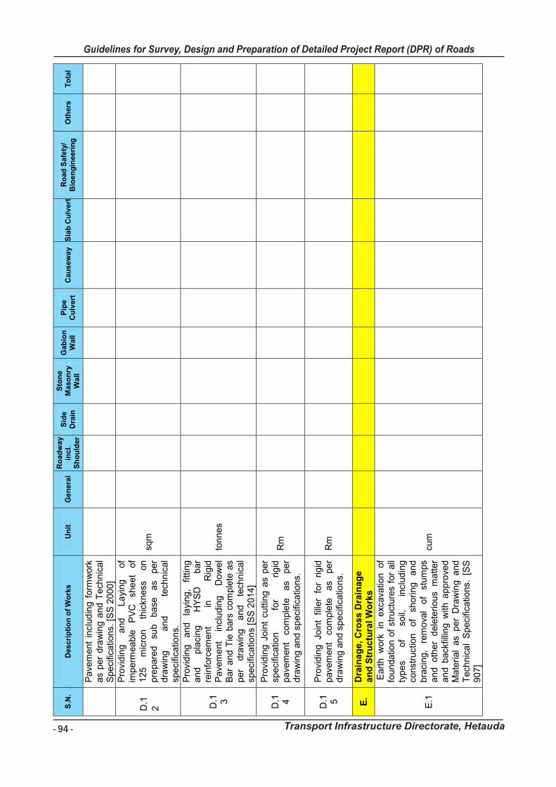
- 94 -
Guidelines for Survey, Design and Preparation of Detailed Project Report (DPR) of Roads
Transport Infrastructure Directorate, Hetauda
Gu
ide
lin
es
fo
r S
urv
ey
Wo
rks I
nc
lud
ing
Pre
pa
rati
on
of
De
tail
ed
Pro
jec
t R
ep
ort
(D
PR
) o
f R
oa
ds
Tra
ns
po
rt I
nfr
as
tru
ctu
re D
irec
tora
te,
He
tau
da
92
S.N
. D
es
cri
pti
on
of
Wo
rks
Un
it
Ge
nera
l R
oad
wa
y in
cl.
Sh
ou
lde
r
Sid
e
Dra
in
Sto
ne
M
aso
nry
W
all
Ga
bio
n
Wa
ll
Pip
e
Cu
lve
rt
Cau
se
wa
y
Sla
b C
ulv
ert
R
oad
Sa
fety
/ B
ioe
ng
ine
eri
ng
O
thers
T
ota
l
Pa
vem
en
t in
clu
din
g f
orm
wo
rk
as
pe
r dra
win
g a
nd
Te
chn
ica
l S
pe
cific
atio
ns.
[S
S 2
00
0]
D
.1
2
Pro
vid
ing
a
nd
L
ayi
ng
o
f im
pe
rme
ab
le
PV
C
she
et
of
12
5
mic
ron
th
ickn
ess
o
n
pre
pa
red
su
b
ba
se
as
pe
r d
raw
ing
a
nd
te
chn
ica
l sp
eci
fica
tion
s.
sqm
D.1 3
Pro
vid
ing
a
nd
la
yin
g,
fittin
g
an
d
pla
cin
g
HY
SD
b
ar
rein
forc
em
en
t in
R
igid
P
ave
me
nt
incl
ud
ing
D
ow
el
Bar
an
d T
ie b
ars
co
mp
lete
as
pe
r d
raw
ing
a
nd
te
chn
ica
l sp
eci
fica
tion
s [S
S 2
01
4]
ton
ne
s
D.1 4
Pro
vid
ing
Jo
int
cu
ttin
g a
s p
er
spe
cific
atio
n
for
rig
id
pa
vem
en
t co
mp
lete
a
s p
er
dra
win
g a
nd
sp
eci
fica
tion
s.
Rm
D.1 5
Pro
vid
ing
Jo
int
fille
r fo
r rig
id
pa
vem
en
t co
mp
lete
a
s p
er
dra
win
g a
nd
sp
eci
fica
tion
s.
Rm
E.
Dra
ina
ge
, C
ros
s D
rain
ag
e
an
d S
tru
ctu
ral
Wo
rks
E.1
Eart
h
wo
rk in
e
xca
vatio
n o
f fo
un
da
tion
of
stru
ctu
res
for
all
typ
es
of
soil,
in
clu
din
g
con
stru
ctio
n
of
sho
rin
g
an
d
bra
cing
, re
mo
val
of
stu
mps
an
d
oth
er
de
lete
rio
us
ma
tte
r a
nd
ba
ckfil
ling
with
ap
pro
ved
M
ate
ria
l a
s p
er
Dra
win
g a
nd
T
ech
nic
al
Sp
eci
fica
tion
s. [S
S
90
7]
cum
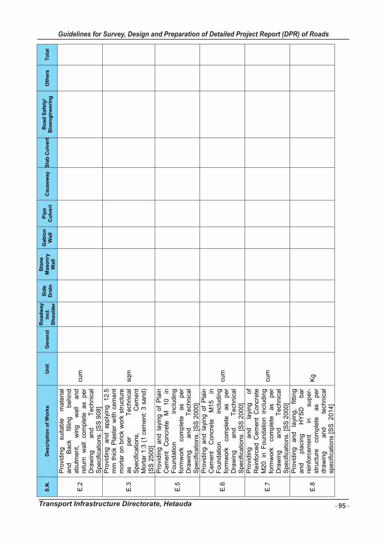
- 95 -
Guidelines for Survey, Design and Preparation of Detailed Project Report (DPR) of Roads
Transport Infrastructure Directorate, Hetauda
Gu
ide
lin
es
fo
r S
urv
ey
Wo
rks I
nc
lud
ing
Pre
pa
rati
on
of
De
tail
ed
Pro
jec
t R
ep
ort
(D
PR
) o
f R
oa
ds
Tra
ns
po
rt I
nfr
as
tru
ctu
re D
irec
tora
te,
He
tau
da
93
S.N
. D
es
cri
pti
on
of
Wo
rks
Un
it
Ge
nera
l R
oad
wa
y in
cl.
Sh
ou
lde
r
Sid
e
Dra
in
Sto
ne
M
aso
nry
W
all
Ga
bio
n
Wa
ll
Pip
e
Cu
lve
rt
Cau
se
wa
y
Sla
b C
ulv
ert
R
oad
Sa
fety
/ B
ioe
ng
ine
eri
ng
O
thers
T
ota
l
E.2
Pro
vid
ing
su
itab
le
ma
terial
an
d
Back
fil
ling
b
eh
ind
a
bu
tme
nt,
w
ing
w
all
an
d
retu
rn
wa
ll co
mp
lete
a
s p
er
Dra
win
g
an
d
Te
chn
ica
l S
pe
cific
atio
ns.
[S
S 9
08
]
cum
E.3
Pro
vid
ing
a
nd
a
pp
lyin
g
12
.5
mm
th
ick P
last
er
with
ce
me
nt
mo
rta
r o
n b
rick
wo
rk s
tru
ctu
re
as
pe
r T
ech
nic
al
Spe
cific
atio
ns,
C
em
en
t M
ort
ar
1:3
(1
ce
me
nt:
3 s
an
d)
[SS
25
00
]
sqm
E.5
Pro
vid
ing
an
d l
ayi
ng
of
Pla
in
Ce
me
nt
Co
ncr
ete
M
1
0
in
Fo
un
da
tion
in
clu
din
g
form
wo
rk
com
ple
te
as
pe
r D
raw
ing
a
nd
T
ech
nic
al
Spe
cific
atio
ns.
[S
S 2
00
0]
E.6
Pro
vid
ing
an
d l
ayi
ng
of
Pla
in
Ce
me
nt
Co
ncr
ete
M
15
in
F
ou
nd
atio
n
inclu
din
g
form
wo
rk
com
ple
te
as
pe
r D
raw
ing
a
nd
T
ech
nic
al
Spe
cific
atio
ns.
[S
S 2
00
0]
cum
E.7
Pro
vid
ing
an
d
layi
ng
o
f R
ein
forc
ed
Ce
me
nt
Co
ncr
ete
M
20
in
F
ou
nd
atio
n
inclu
din
g
form
wo
rk
com
ple
te
as
pe
r D
raw
ing
a
nd
T
ech
nic
al
Spe
cific
atio
ns.
[S
S 2
00
0]
cum
E.8
Pro
vid
ing
a
nd
la
yin
g,
fittin
g
an
d
pla
cin
g
HY
SD
b
ar
rein
forc
em
en
t in
su
pe
r-st
ruct
ure
co
mp
lete
a
s p
er
dra
win
g
an
d
tech
nic
al
spe
cific
atio
ns
[SS
2
01
4]
Kg

- 96 -
Guidelines for Survey, Design and Preparation of Detailed Project Report (DPR) of Roads
Transport Infrastructure Directorate, Hetauda
Gu
idelin
es f
or
Su
rvey
Wo
rks In
clu
din
g P
rep
ara
tio
n o
f D
eta
iled
Pro
ject
Rep
ort
(D
PR
) o
f R
oad
s
Tra
nsp
ort
In
frastr
uctu
re D
irecto
rate
, H
eta
ud
a
94
S.N
. D
escri
pti
on
of
Wo
rks
Un
it
Gen
era
l R
oad
wa
y in
cl.
Sh
ou
lder
Sid
e
Dra
in
Sto
ne
Maso
nry
W
all
Gab
ion
W
all
Pip
e
Cu
lvert
C
au
sew
ay
Sla
b C
ulv
ert
R
oad
Safe
ty/
Bio
en
gin
eeri
ng
O
thers
T
ota
l
E.9
Pro
vid
ing
and
layi
ng
Plu
m
concr
ete
(B
ould
er
mix
ed
concr
ete
) as
per
Dra
win
g a
nd
Speci
ficatio
ns,
60%
M
15
concr
ete
an
d
40%
bou
lders
/sto
nes
[SS
2416
]
cum
E.1 0
Pro
vid
ing
and
La
ying
Rein
forc
ed
cem
ent
concr
ete
N
P3
Flu
sh
join
ted
pip
e
for
culv
ert
s in
clud
ing
fix
ing
with
ce
ment
mort
ar
1:2
as
per
Dra
win
g
an
d
Tech
nic
al
Speci
ficatio
ns.
, 4
50
mm
in
tern
al d
ia.
[SS
70
1]
mete
r
E.1 1
Pro
vid
ing
and
La
ying
Rein
forc
ed
cem
ent
concr
ete
N
P3
Flu
sh
join
ted
pip
e
for
culv
ert
s in
clud
ing
fix
ing
with
ce
ment
mort
ar
1:2
as
per
Dra
win
g
an
d
Tech
nic
al
Speci
ficatio
ns.
, 6
00
mm
in
tern
al d
ia.
[SS
70
1]
mete
r
E.1 2
Pro
vid
ing
and
La
ying
Rein
forc
ed
cem
ent
concr
ete
N
P3
Flu
sh
join
ted
pip
e
for
culv
ert
s in
clud
ing
fix
ing
with
ce
ment
mort
ar
1:2
as
per
Dra
win
g
an
d
Tech
nic
al
Speci
ficatio
ns.
, 9
00
mm
in
tern
al d
ia. [S
S 7
01]
mete
r
E.1 3
Pro
vid
ing
and
La
ying
Rein
forc
ed
cem
ent
concr
ete
N
P3
Flu
sh
join
ted
pip
e
for
culv
ert
s in
clud
ing
fix
ing
with
ce
ment
mort
ar
1:2
as
per
Dra
win
g
an
d
Tech
nic
al
Speci
ficatio
ns.
, 1
200
mm
in
tern
al d
ia. [S
S 7
01]
mete
r
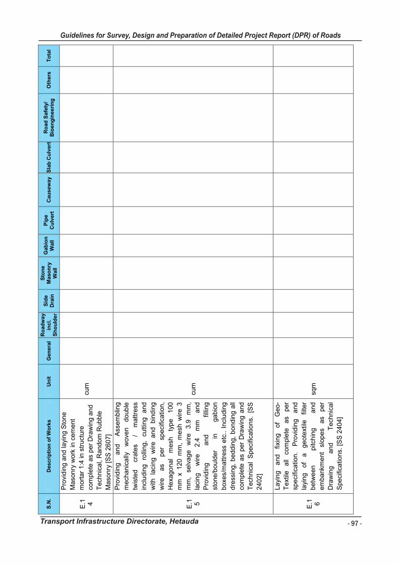
- 97 -
Guidelines for Survey, Design and Preparation of Detailed Project Report (DPR) of Roads
Transport Infrastructure Directorate, Hetauda
Gu
idelin
es f
or
Su
rvey
Wo
rks In
clu
din
g P
rep
ara
tio
n o
f D
eta
iled
Pro
ject
Rep
ort
(D
PR
) o
f R
oad
s
Tra
nsp
ort
In
frastr
uctu
re D
irecto
rate
, H
eta
ud
a
95
S.N
. D
escri
pti
on
of
Wo
rks
Un
it
Gen
era
l R
oad
wa
y in
cl.
Sh
ou
lder
Sid
e
Dra
in
Sto
ne
Maso
nry
W
all
Gab
ion
W
all
Pip
e
Cu
lvert
C
au
sew
ay
Sla
b C
ulv
ert
R
oad
Safe
ty/
Bio
en
gin
eeri
ng
O
thers
T
ota
l
E.1 4
Pro
vid
ing
an
d la
yin
g S
tone
Maso
nry
work
in c
em
ent
mort
ar
1:4
in s
truct
ure
com
ple
te a
s per
Dra
win
g a
nd
Tech
nic
al,
Rand
om
Rubble
Maso
nry
[S
S 2
60
7]
cum
E.1 5
Pro
vid
ing
an
d
Ass
em
blin
g
mech
anic
ally
w
ove
n
dou
ble
twis
ted
cr
ate
s /
mattre
ss
incl
udin
g
rolli
ng,
cutt
ing
and
with
la
cing
wire
and
b
ind
ing
wire
as
per
speci
fication,
Hexa
go
nal
mesh
ty
pe
100
mm
x 1
20 m
m,
mesh
wire 3
mm
, se
lvage
wire
3.9
m
m,
laci
ng
wire
2.4
m
m
and
Pro
vid
ing
a
nd
fil
ling
stone/b
ou
lder
in
gab
ion
boxe
s/m
attre
ss e
tc.. I
ncl
udin
g
dre
ssin
g,
bedd
ing,
bo
nd
ing
all
com
ple
te a
s per
Dra
win
g a
nd
Tech
nic
al
Speci
ficatio
ns.
[S
S
2402]
cum
E.1 6
La
yin
g
and
fixin
g
of
Geo
-
Text
ile
all
com
ple
te
as
per
speci
ficatio
n.
Pro
vidin
g
and
layi
ng
of
a
geo
text
ile
filte
r
betw
een
pitc
hin
g
and
em
bankm
ent
slopes
as
per
Dra
win
g
an
d
Tech
nic
al
Speci
ficatio
ns.
[S
S 2
404
]
sqm

- 98 -
Guidelines for Survey, Design and Preparation of Detailed Project Report (DPR) of Roads
Transport Infrastructure Directorate, Hetauda
Gu
idelin
es f
or
Su
rvey
Wo
rks In
clu
din
g P
rep
ara
tio
n o
f D
eta
iled
Pro
ject
Rep
ort
(D
PR
) o
f R
oad
s
Tra
nsp
ort
In
frastr
uctu
re D
irecto
rate
, H
eta
ud
a
96
S.N
. D
escri
pti
on
of
Wo
rks
Un
it
Gen
era
l R
oad
wa
y in
cl.
Sh
ou
lder
Sid
e
Dra
in
Sto
ne
Maso
nry
W
all
Gab
ion
W
all
Pip
e
Cu
lvert
C
au
sew
ay
Sla
b C
ulv
ert
R
oad
Safe
ty/
Bio
en
gin
eeri
ng
O
thers
T
ota
l
G.
Ro
ad
Fu
rnit
ure
an
d T
raff
ic
Safe
ty M
easu
res
G.1
Non R
efle
ctiv
e T
raff
ic S
igns,
Pro
vid
ing
an
d
fixin
g
of
Non
reflect
ive
warn
ing,
mandato
ry
and i
nfo
rmato
ry s
ign b
oard
of
2
mm
th
ick
MS
S
he
et
with
back
su
pport
fr
am
e fix
ed on
hea
vy
50
m
m
tube
or
Chan
nel
sect
ion o
f 75 m
m X
40
mm
fir
mly
fix
ed
to
the
gro
un
d b
y m
eans
of
pro
perl
y
desi
gned
foun
datio
n
with
M
10/4
0 g
rade
cem
ent
concr
ete
300 m
m x
300 m
m x
300 m
m,
l as
per
dra
win
gs
and
Tech
nic
al
Speci
ficatio
n/
DO
R
Pub
lication., M
ild S
teel
Angle
Iron 7
5 *
40 *
6 m
m,
3 m
long
@ 6
.8 k
g/m
, M
S S
he
et
90 c
m
heig
ht
equ
ilate
ral t
riang
le
[SS
1501]
no
G.2
Pro
vidin
g
and
layi
ng
of
hot
app
lied
therm
opla
stic
com
pound a
t le
ast
2 m
m t
hic
k
incl
udin
g
reflect
ori
zing
gla
ss
beads
as
per
DO
R
Tra
ffic
sign
manual/
Speci
ficatio
ns
[SS
15
04]
sqm
G.3
Retr
o-R
efle
ctori
zed
Tra
ffic
Sig
ns,
Pro
vid
ing
an
d f
ixin
g o
f
retr
o-
reflect
ori
zed
warn
ing,
Regu
lato
ry
and
in
form
ato
ry
sign
as
per
speci
fication
no

- 99 -
Guidelines for Survey, Design and Preparation of Detailed Project Report (DPR) of Roads
Transport Infrastructure Directorate, Hetauda
Gu
idelin
es f
or
Su
rvey
Wo
rks In
clu
din
g P
rep
ara
tio
n o
f D
eta
iled
Pro
ject
Rep
ort
(D
PR
) o
f R
oad
s
Tra
nsp
ort
In
frastr
uctu
re D
irecto
rate
, H
eta
ud
a
97
S.N
. D
escri
pti
on
of
Wo
rks
Un
it
Gen
era
l R
oad
wa
y in
cl.
Sh
ou
lder
Sid
e
Dra
in
Sto
ne
Maso
nry
W
all
Gab
ion
W
all
Pip
e
Cu
lvert
C
au
sew
ay
Sla
b C
ulv
ert
R
oad
Safe
ty/
Bio
en
gin
eeri
ng
O
thers
T
ota
l
clause
150
1
made
of
hig
h
inte
nsi
ty
gra
de
sheetin
g
,
fixed o
ver
alu
min
um
sheetin
g,
1.5
mm
thic
k s
upport
ed o
n a
50 m
m i
nte
rnal
dia
ste
el
tube
or
mild
ste
el
ang
le i
ron p
ost
75
mm
x
40
mm
x
6
mm
firm
ly f
ixed t
o t
he g
rou
nd
by
means
of
pro
perl
y desi
gn
ed
foundatio
n
with
M
1
0/4
0
gra
de
cem
ent
concr
ete
30 c
m
x 30 c
m , 3
0 c
m b
elo
w g
rou
nd
leve
l or
as
per
Dra
win
g a
nd
Tech
nic
al
Spe
cific
atio
ns.
, M
S
She
et
90
cm
heig
ht
equ
ilate
ral
tria
ngle
[N
orm
s S
.
No.
15.2
an
d
Ref
to
SS
clause
No 1
501]
G.4
Pro
vid
ing
an
d
Fix
ing
Rein
forc
ed
cem
ent
concr
ete
M
15
gra
de
kilo
mete
r P
ost
incl
udin
g p
ain
ting
an
d p
rinting
as
per
Sta
nd
ard
D
raw
ing-
2070
an
d
Tech
nic
al
Speci
ficatio
ns.
posi
tion,
Fiv
e
kilo
mete
r P
ost
(p
reca
st)
[SS
1506]
no
G.5
Kilo
mete
r S
tone,
Pro
vidin
g
and F
ixin
g R
ein
forc
ed c
em
ent
concr
ete
M 1
5 g
rade
kilo
mete
r P
ost
incl
udin
g
pain
ting a
nd p
rintin
g a
s p
er
Sta
ndard
Dra
win
g-2
070 a
nd
no

- 100 -
Guidelines for Survey, Design and Preparation of Detailed Project Report (DPR) of Roads
Transport Infrastructure Directorate, Hetauda
Gu
ide
lin
es
fo
r S
urv
ey
Wo
rks I
nc
lud
ing
Pre
pa
rati
on
of
De
tail
ed
Pro
jec
t R
ep
ort
(D
PR
) o
f R
oa
ds
Tra
ns
po
rt I
nfr
as
tru
ctu
re D
irec
tora
te,
He
tau
da
98
S.N
. D
escri
pti
on
of
Wo
rks
Un
it
Gen
era
l R
oad
wa
y in
cl.
Sh
ou
lder
Sid
e
Dra
in
Sto
ne
Maso
nry
W
all
Gab
ion
W
all
Pip
e
Cu
lvert
C
au
sew
ay
Sla
b C
ulv
ert
R
oad
Safe
ty/
Bio
en
gin
eeri
ng
O
thers
T
ota
l
Te
chn
ica
l Sp
eci
fica
tion
s.
po
sitio
n,
On
e k
ilom
ete
r p
ost
(pre
cast
) [S
S1
50
6]
G.6
Pro
vid
ing
a
nd
in
sta
llatio
n
of
15
0
mm
*
15
0
mm
1
. 5
m
lon
g
de
line
ato
rs
po
st
(ro
ad
wa
y in
dic
ato
rs,
ha
zard
ma
rkers
, o
bje
ct m
ark
ers
), 8
0-
10
0
cm
hig
h
ab
ove
g
rou
nd
leve
l, p
ain
ted
bla
ck a
nd
wh
ite
in 2
0 c
m w
ide
str
ips,
bu
rie
d o
r
pre
sse
d in
to t
he
g
rou
nd
a
nd
con
form
ing
to
th
e
dra
win
gs
an
d T
ech
nic
al
Specifi
catio
ns.
[SS
15
07
]
no
G.7
Pro
vid
ing
an
d e
rect
ing
a "
W"
me
tal
be
am
cr
ash
b
arr
ier
com
prisi
ng
o
f 3
m
m
thic
k
corr
ug
ate
d s
he
et
me
tal
be
am
rail,
70
cm
ab
ove
ro
ad
/gro
un
d
leve
l, fix
ed
o
n
ISM
C
seri
es
cha
nn
el
vert
ica
l p
ost
, 1
50
x
75
x 5
mm
sp
ace
d 2
m c
ente
r
to c
en
ter,
1.8
m h
igh
, 1
.1 m
be
low
gro
un
d/r
oa
d le
vel m
eta
l
be
am
ra
il to
be
fix
ed
on
th
e
vert
ica
l p
ost
with
a s
pa
cer
of
cha
nn
el
sect
ion
15
0 x
75
x 5
mm
, 3
30
m
m lo
ng
co
mp
lete
as
pe
r D
raw
ing
an
d T
ech
nic
al
Spe
cific
atio
ns.
[S
S 1
50
9]
me
ter

- 101 -
Guidelines for Survey, Design and Preparation of Detailed Project Report (DPR) of Roads
Transport Infrastructure Directorate, Hetauda
Gu
ide
lin
es
fo
r S
urv
ey
Wo
rks I
nc
lud
ing
Pre
pa
rati
on
of
De
tail
ed
Pro
jec
t R
ep
ort
(D
PR
) o
f R
oa
ds
Tra
ns
po
rt I
nfr
as
tru
ctu
re D
irec
tora
te,
He
tau
da
99
S.N
. D
escri
pti
on
of
Wo
rks
Un
it
Gen
era
l R
oad
wa
y in
cl.
Sh
ou
lder
Sid
e
Dra
in
Sto
ne
Maso
nry
W
all
Gab
ion
W
all
Pip
e
Cu
lvert
C
au
sew
ay
Sla
b C
ulv
ert
R
oad
Safe
ty/
Bio
en
gin
eeri
ng
O
thers
T
ota
l
H.
Bio
En
gin
ee
rin
g
Wo
rks
/Pla
nta
tio
n W
ork
s
H.1
Pre
pa
ratio
n
of
Slo
pe
s fo
r
Bio
en
gin
ee
rin
g O
pe
ratio
n [
SS
28
06
]
sqm
H.2
Pla
ntin
g o
f ro
ote
d g
rass
slip
s
on
th
e
slo
pe
s in
clu
din
g
pre
pa
ratio
n
of
slip
s o
n
the
site
. [S
S 2
80
7]
sqm
H.3
Pla
ntin
g
con
tain
eri
zed
tr
ee
an
d
shru
b
see
dlin
gs,
incl
ud
ing
p
ittin
g,
tra
nsp
lan
ting
, co
mp
ost
ing
an
d
mu
lch
ing
. [
SS
28
07
]
no
H.4
Gra
ss
sod
din
g
wo
rks
incl
ud
ing
so
d
cutt
ing
,
tra
nsp
ort
ing
, p
laci
ng
in
po
sitio
n a
nd
w
ate
r sp
rinklin
g
[SS
28
12
]
sqm
H.5
Pre
pa
ratio
n
an
d
pla
ntin
g
of
live
pe
gs
sele
cte
d
spe
cie
s
(e.g
a
ssu
ro,
na
md
i p
hu
l,
sim
ali
) o
f m
inim
um
len
gth
to
0.5
m d
ep
th i
n t
o a
ny
gro
un
d
surf
ace
. [S
S 2
80
7]
me
ter
H.6
Pre
pa
ratio
n a
nd
La
yin
g o
f liv
e
fasc
ine
s u
sin
g l
ive
ha
rdw
oo
d
cutt
ing
of
sele
cte
d s
pe
cie
s o
f
min
imum
le
ng
th
pla
ced
in
bu
nd
les
incl
ud
ing
b
ack
fillin
g
of
tre
nch
a
nd
ca
refu
l
com
pa
ctio
n [
SS
28
07
]
me
ter
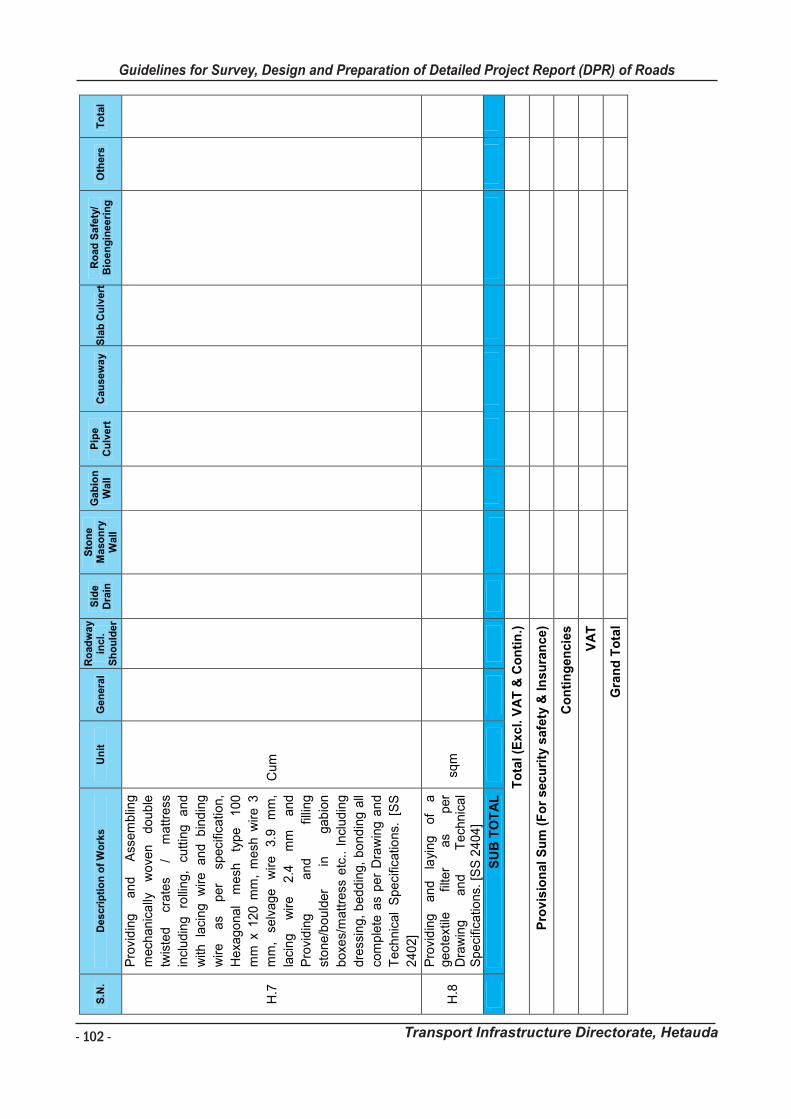
- 102 -
Guidelines for Survey, Design and Preparation of Detailed Project Report (DPR) of Roads
Transport Infrastructure Directorate, Hetauda
Gu
ide
lin
es
fo
r S
urv
ey
Wo
rks I
nc
lud
ing
Pre
pa
rati
on
of
De
tail
ed
Pro
jec
t R
ep
ort
(D
PR
) o
f R
oa
ds
Tra
ns
po
rt I
nfr
as
tru
ctu
re D
irec
tora
te,
He
tau
da
10
0
S.N
. D
es
cri
pti
on
of
Wo
rks
Un
it
Gen
era
l R
oad
wa
y in
cl.
Sh
ou
lder
Sid
e
Dra
in
Sto
ne
Maso
nry
W
all
Gab
ion
W
all
Pip
e
Cu
lvert
C
au
sew
ay
Sla
b C
ulv
ert
R
oad
Safe
ty/
Bio
en
gin
eeri
ng
O
thers
T
ota
l
H.7
Pro
vid
ing
a
nd
A
sse
mb
ling
mech
an
ica
lly
wo
ven
d
ou
ble
twis
ted
cr
ate
s /
ma
ttre
ss
incl
ud
ing
ro
llin
g,
cutt
ing
a
nd
with
la
cin
g
wire
a
nd
b
ind
ing
wire
a
s p
er
spe
cific
atio
n,
He
xag
on
al
me
sh
typ
e
10
0
mm
x 1
20
mm
, m
esh
wire
3
mm
, se
lva
ge
w
ire
3
.9
mm
,
laci
ng
w
ire
2
.4
mm
a
nd
Pro
vid
ing
a
nd
fil
ling
sto
ne
/bo
uld
er
in
ga
bio
n
bo
xes/
ma
ttre
ss e
tc..
In
clu
din
g
dre
ssin
g,
be
dd
ing
, b
on
din
g a
ll
com
ple
te a
s p
er
Dra
win
g a
nd
Te
chn
ica
l S
pe
cific
atio
ns.
[S
S
24
02
]
Cu
m
H.8
Pro
vid
ing
a
nd
layi
ng
o
f a
g
eo
text
ile
filte
r a
s p
er
Dra
win
g
an
d
Te
chn
ica
l S
pe
cific
atio
ns.
[S
S 2
40
4]
sq
m
S
UB
TO
TA
L
To
tal
(Exc
l. V
AT
& C
on
tin
.)
Pro
vis
ion
al
Su
m (
Fo
r s
ec
uri
ty s
afe
ty &
In
su
ran
ce
)
Co
nti
ng
en
cie
s
VA
T
Gra
nd
To
tal
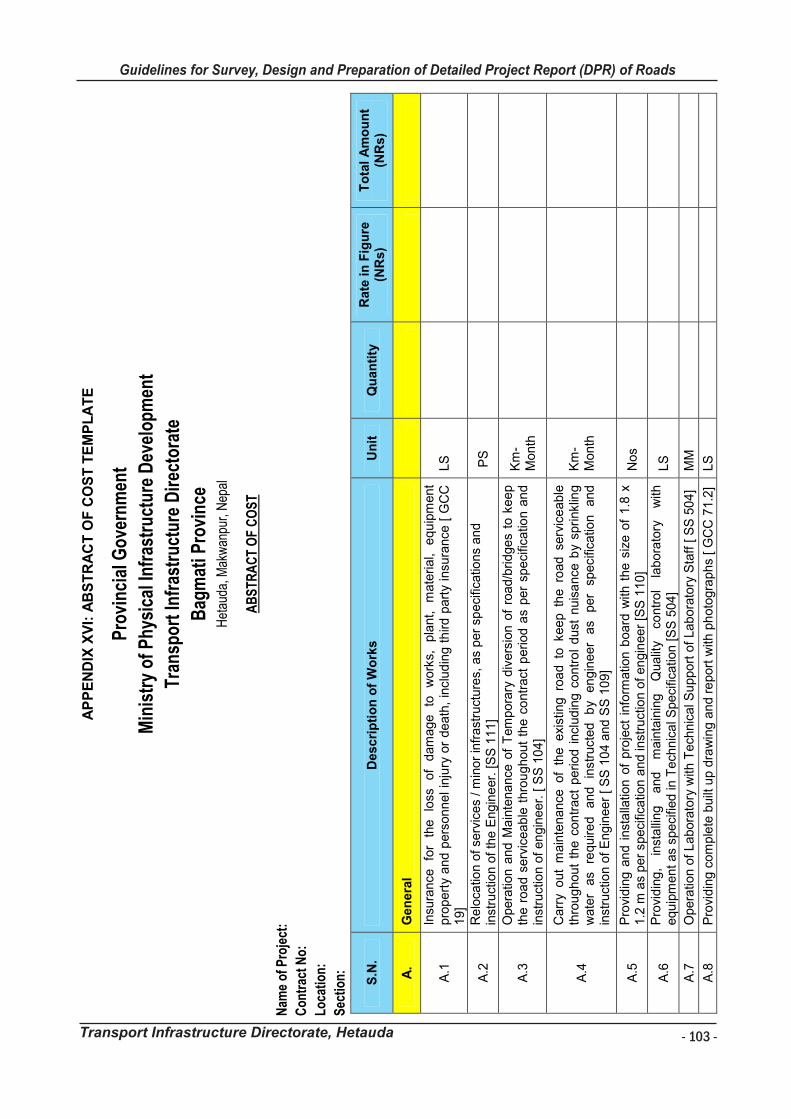
- 103 -
Guidelines for Survey, Design and Preparation of Detailed Project Report (DPR) of Roads
Transport Infrastructure Directorate, Hetauda
Gu
ide
lin
es
fo
r S
urv
ey
Wo
rks I
nc
lud
ing
Pre
pa
rati
on
of
De
tail
ed
Pro
jec
t R
ep
ort
(D
PR
) o
f R
oa
ds
Tra
ns
po
rt I
nfr
as
tru
ctu
re D
irec
tora
te,
He
tau
da
10
1
AP
PE
ND
IX X
VI:
AB
ST
RA
CT
OF
CO
ST
TE
MP
LA
TE
Pro
vinc
ial G
over
nmen
t
Min
istr
y of
Phy
sica
l Inf
rast
ruct
ure
Dev
elop
men
t
Tran
spor
t Inf
rast
ruct
ure
Dir
ecto
rate
Bag
mat
i Pro
vinc
e H
etau
da, M
akw
anpu
r, N
epal
AB
STR
AC
T O
F C
OS
T
Nam
e of
Pro
ject
:
Con
trac
t No:
Loca
tion:
Sec
tion:
S.N
. D
es
cri
pti
on
of
Wo
rks
U
nit
Q
ua
nti
ty
Ra
te i
n F
igu
re
(NR
s)
To
tal
Am
ou
nt
(NR
s)
A.
Ge
ne
ral
A.1
In
sura
nce
fo
r th
e
loss
o
f d
am
ag
e
to
wo
rks,
p
lan
t,
ma
terial,
eq
uip
me
nt
pro
pe
rty
an
d p
ers
on
ne
l in
jury
or
de
ath
, in
clu
din
g t
hird
pa
rty
insu
ran
ce [
GC
C
19
]
LS
A.2
R
elo
catio
n o
f se
rvic
es
/ m
ino
r in
fra
stru
ctu
res,
as
pe
r sp
eci
fica
tion
s a
nd
in
stru
ctio
n o
f th
e E
ng
ine
er.
[S
S 1
11
] P
S
A.3
O
pe
ratio
n a
nd
Ma
inte
na
nce
of
Tem
po
rary
div
ers
ion
of
roa
d/b
rid
ge
s to
ke
ep
th
e r
oa
d s
erv
ice
ab
le t
hro
ug
ho
ut
the
co
ntr
act
pe
rio
d a
s p
er
spe
cific
atio
n a
nd
in
stru
ctio
n o
f e
ng
ine
er.
[ S
S 1
04
]
Km
-M
on
th
A.4
Ca
rry
ou
t m
ain
ten
an
ce o
f th
e e
xist
ing
ro
ad
to
ke
ep
th
e r
oa
d s
erv
ice
ab
le
thro
ug
ho
ut
the
co
ntr
act
pe
rio
d i
ncl
ud
ing
co
ntr
ol
du
st n
uis
an
ce b
y sp
rinklin
g
wa
ter
as
req
uire
d
an
d
inst
ruct
ed
b
y e
ng
ine
er
as
pe
r sp
ecifi
catio
n
an
d
inst
ruct
ion
of
En
gin
ee
r [
SS
10
4 a
nd
SS
10
9]
Km
-M
on
th
A.5
P
rovi
din
g a
nd
inst
alla
tion
of
pro
ject
info
rma
tion
bo
ard
with
th
e s
ize
of
1.8
x
1.2
m a
s p
er
spe
cific
atio
n a
nd
inst
ruct
ion
of
en
gin
ee
r [S
S 1
10
] N
os
A.6
P
rovi
din
g,
inst
alli
ng
a
nd
m
ain
tain
ing
Q
ua
lity
con
tro
l la
bo
rato
ry
with
e
qu
ipm
en
t as
spe
cifie
d in
Te
chn
ica
l Spe
cific
atio
n [S
S 5
04
] L
S
A.7
O
pe
ratio
n o
f L
ab
ora
tory
with
Te
chn
ica
l Su
pp
ort
of
La
bo
rato
ry S
taff
[ S
S 5
04
] M
M
A
.8
Pro
vid
ing
co
mp
lete
bu
ilt u
p d
raw
ing
an
d r
ep
ort
with
ph
oto
gra
ph
s [
GC
C 7
1.2
] L
S
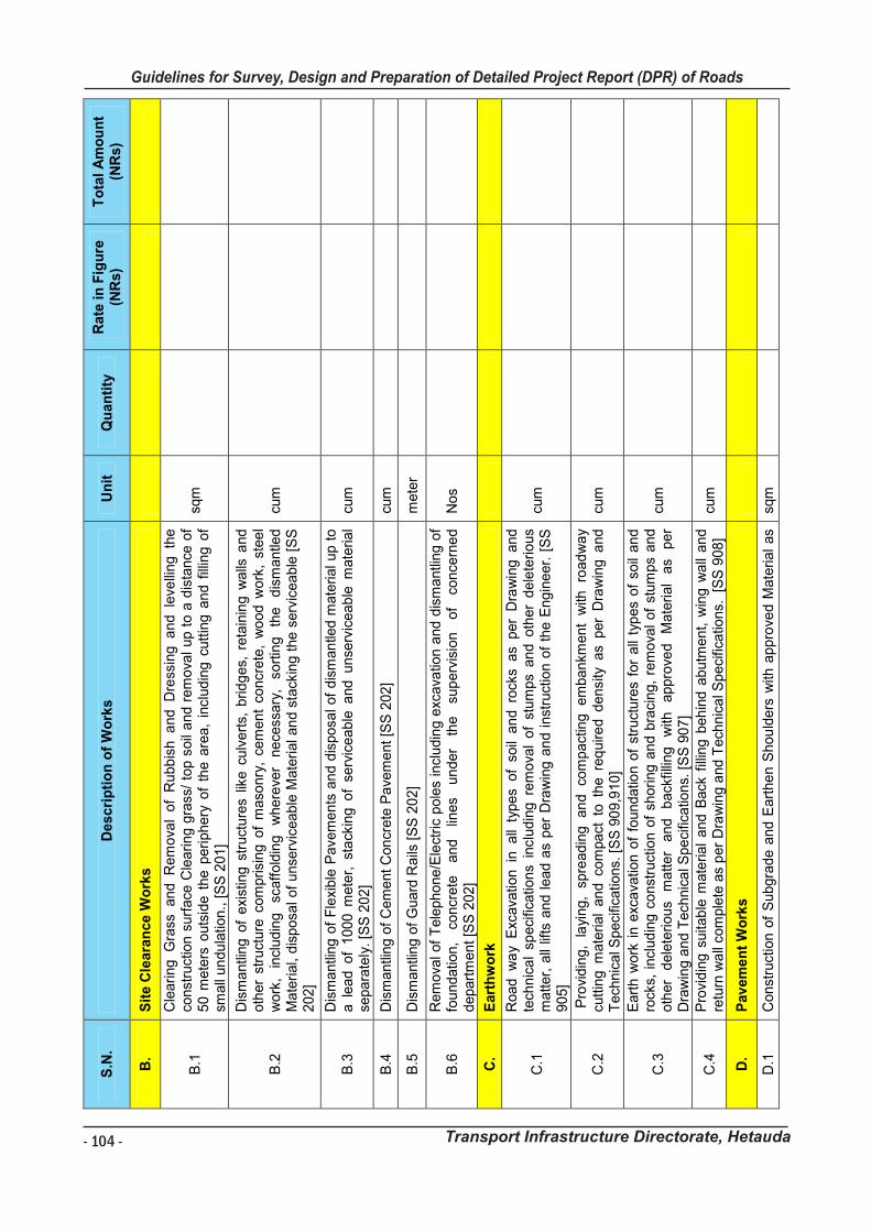
- 104 -
Guidelines for Survey, Design and Preparation of Detailed Project Report (DPR) of Roads
Transport Infrastructure Directorate, Hetauda
Gu
ide
lin
es
fo
r S
urv
ey
Wo
rks I
nc
lud
ing
Pre
pa
rati
on
of
De
tail
ed
Pro
jec
t R
ep
ort
(D
PR
) o
f R
oa
ds
Tra
ns
po
rt I
nfr
as
tru
ctu
re D
irec
tora
te,
He
tau
da
10
2
S.N
. D
es
cri
pti
on
of
Wo
rks
U
nit
Q
ua
nti
ty
Ra
te i
n F
igu
re
(NR
s)
To
tal
Am
ou
nt
(NR
s)
B.
Sit
e C
lea
ran
ce
Wo
rks
B.1
Cle
ari
ng
G
rass
a
nd
R
em
ova
l o
f R
ub
bis
h a
nd
D
ress
ing
a
nd
le
velli
ng
th
e
con
stru
ctio
n s
urf
ace
Cle
ari
ng
gra
ss/
top
so
il a
nd
re
mo
val u
p t
o a
dis
tan
ce o
f 5
0 m
ete
rs o
uts
ide
th
e p
eri
ph
ery
of
the
are
a,
incl
ud
ing
cu
ttin
g a
nd
fill
ing
of
sma
ll u
nd
ula
tion.,
[S
S 2
01
]
sqm
B.2
Dis
ma
ntli
ng
of
exi
stin
g s
tru
ctu
res
like
cu
lve
rts,
brid
ge
s, r
eta
inin
g w
alls
an
d
oth
er
stru
ctu
re c
om
prisi
ng
of
ma
son
ry,
cem
en
t co
ncre
te,
wo
od
wo
rk,
ste
el
wo
rk,
incl
ud
ing
sc
aff
old
ing
wh
ere
ver
ne
cess
ary
, so
rtin
g
the
d
ism
an
tled
M
ate
rial,
dis
po
sal o
f u
nse
rvic
ea
ble
Ma
teri
al a
nd
sta
ckin
g t
he
se
rvic
ea
ble
[S
S
20
2]
cum
B.3
D
ism
an
tling
of
Fle
xib
le P
ave
me
nts
an
d d
isp
osa
l o
f d
ism
an
tled
ma
terial u
p t
o
a l
ea
d o
f 1
00
0 m
ete
r, s
tack
ing
of
serv
ice
ab
le a
nd
un
serv
ice
ab
le m
ate
ria
l se
pa
rate
ly.
[SS
20
2]
cum
B.4
D
ism
an
tling
of
Ce
me
nt
Con
cre
te P
ave
me
nt
[SS
20
2]
cum
B.5
D
ism
an
tling
of
Gu
ard
Ra
ils [
SS
20
2]
me
ter
B.6
R
em
ova
l o
f T
ele
ph
on
e/E
lect
ric
po
les
incl
ud
ing
exc
ava
tion
an
d d
ism
an
tlin
g o
f fo
un
da
tion
, co
ncr
ete
a
nd
lin
es
un
de
r th
e
sup
erv
isio
n
of
con
cern
ed
d
ep
art
me
nt
[SS
20
2]
No
s
C.
Eart
hw
ork
C.1
Ro
ad
w
ay
Exc
ava
tion
in
a
ll ty
pe
s o
f so
il a
nd
ro
cks
as
pe
r D
raw
ing
a
nd
te
chn
ica
l sp
eci
fica
tion
s in
clud
ing
re
mo
val
of
stu
mp
s a
nd
oth
er
de
lete
rio
us
ma
tte
r, a
ll lif
ts a
nd
le
ad
as
pe
r D
raw
ing
an
d i
nst
ruct
ion
of
the
Eng
ine
er.
[S
S
90
5]
cum
C.2
P
rovi
din
g,
layi
ng
, sp
rea
din
g
an
d
com
pa
ctin
g
em
ba
nkm
en
t w
ith
roa
dw
ay
cutt
ing
ma
terial
an
d c
om
pa
ct t
o t
he
re
qu
ire
d d
en
sity
as
pe
r D
raw
ing
an
d
Te
chn
ica
l Sp
eci
fica
tion
s. [
SS
90
9,9
10
] cu
m
C.3
Eart
h w
ork
in e
xca
vatio
n o
f fo
un
da
tion
of
stru
ctu
res
for
all
typ
es
of
soil
an
d
rock
s, i
ncl
ud
ing
co
nst
ruct
ion
of
sho
ring
an
d b
raci
ng
, re
mo
val
of
stu
mp
s a
nd
o
ther
de
lete
rio
us
ma
tte
r a
nd
b
ack
fillin
g
with
a
pp
rove
d
Ma
teri
al
as
pe
r D
raw
ing
an
d T
ech
nic
al S
pe
cific
atio
ns.
[S
S 9
07
]
cum
C.4
P
rovi
din
g s
uita
ble
ma
teria
l a
nd
Back
fill
ing
be
hin
d a
bu
tme
nt,
win
g w
all
an
d
retu
rn w
all
com
ple
te a
s p
er
Dra
win
g a
nd
Te
chn
ica
l Sp
eci
fica
tion
s.
[SS
90
8]
cum
D.
Pav
em
en
t W
ork
s
D.1
C
on
stru
ctio
n o
f S
ub
gra
de
an
d E
art
he
n S
ho
uld
ers
with
ap
pro
ved
Ma
teria
l a
s sq
m
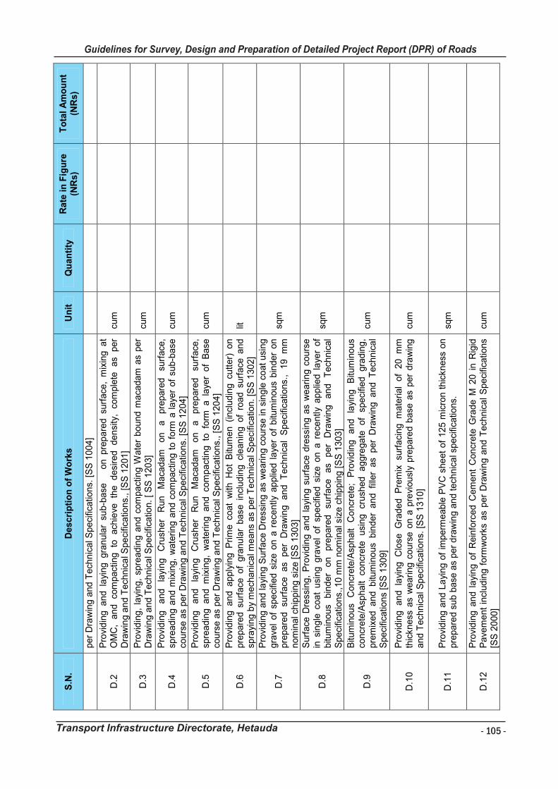
- 105 -
Guidelines for Survey, Design and Preparation of Detailed Project Report (DPR) of Roads
Transport Infrastructure Directorate, Hetauda
Gu
ide
lin
es
fo
r S
urv
ey
Wo
rks I
nc
lud
ing
Pre
pa
rati
on
of
De
tail
ed
Pro
jec
t R
ep
ort
(D
PR
) o
f R
oa
ds
Tra
ns
po
rt I
nfr
as
tru
ctu
re D
irec
tora
te,
He
tau
da
10
3
S.N
. D
es
cri
pti
on
of
Wo
rks
U
nit
Q
ua
nti
ty
Ra
te i
n F
igu
re
(NR
s)
To
tal
Am
ou
nt
(NR
s)
pe
r D
raw
ing
an
d T
ech
nic
al S
pe
cific
atio
ns.
[S
S 1
00
4]
D.2
P
rovi
din
g a
nd
la
yin
g g
ran
ula
r su
b-b
ase
o
n p
rep
are
d s
urf
ace
, m
ixin
g a
t O
MC
, a
nd
co
mp
act
ing
to
ach
ieve
th
e
de
sire
d
de
nsi
ty,
com
ple
te
as
pe
r D
raw
ing
an
d T
ech
nic
al S
pe
cific
atio
ns.
, [S
S 1
20
1]
cum
D.3
P
rovi
din
g,
layi
ng
, sp
rea
din
g a
nd
co
mp
act
ing W
ate
r b
ou
nd
ma
cad
am
as
pe
r D
raw
ing
an
d T
ech
nic
al S
pe
cific
atio
n.
[ S
S 1
20
3]
cum
D.4
P
rovi
din
g
an
d
layi
ng
C
rush
er
Ru
n
Ma
cad
am
o
n
a
pre
pa
red
su
rfa
ce,
spre
ad
ing
an
d m
ixin
g,
wa
terin
g a
nd
co
mp
act
ing t
o f
orm
a l
aye
r o
f su
b-b
ase
co
urs
e a
s p
er
Dra
win
g a
nd
Te
chn
ica
l Sp
eci
fica
tion
s. [
SS
12
04
] cu
m
D.5
P
rovi
din
g
an
d
layi
ng
C
rush
er
Ru
n
Ma
cad
am
o
n
a
pre
pa
red
su
rfa
ce,
spre
ad
ing
a
nd
m
ixin
g,
wa
terin
g a
nd
co
mp
act
ing to
fo
rm a
la
yer
of
Base
co
urs
e a
s p
er
Dra
win
g a
nd
Te
chn
ica
l Sp
eci
fica
tion
s.,
[SS
12
04
] cu
m
D.6
P
rovi
din
g a
nd
ap
ply
ing
Pri
me
co
at
with
Ho
t B
itum
en
(in
clu
din
g c
utt
er)
on
p
rep
are
d s
urf
ace
of
gra
nu
lar
ba
se i
ncl
ud
ing
cle
an
ing
of
roa
d s
urf
ace
an
d
spra
yin
g b
y m
ech
an
ica
l me
an
s a
s p
er
Te
chn
ica
l Sp
eci
fica
tion
. [S
S 1
30
2]
lit
D.7
Pro
vid
ing
an
d la
yin
g S
urf
ace
Dre
ssin
g a
s w
ea
rin
g c
ou
rse
in s
ing
le c
oa
t u
sin
g
gra
vel
of
spe
cifie
d s
ize
on
a r
ece
ntly
ap
plie
d l
aye
r o
f b
itum
ino
us
bin
de
r o
n
pre
pa
red
su
rfa
ce
as
pe
r D
raw
ing
a
nd
T
ech
nic
al
Sp
eci
fica
tion
s.,
19
m
m
no
min
al c
hip
pin
g s
ize
[S
S 1
30
3]
sqm
D.8
Surf
ace
Dre
ssin
g,
Pro
vid
ing
an
d l
ayi
ng
su
rfa
ce d
ress
ing
as
we
arin
g c
ou
rse
in
sin
gle
co
at
usi
ng
gra
vel
of
spe
cifie
d s
ize o
n a
re
cen
tly
ap
plie
d l
aye
r o
f b
itum
ino
us
bin
de
r o
n
pre
pa
red
su
rfa
ce
as
pe
r D
raw
ing
a
nd
T
ech
nic
al
Spe
cific
atio
ns.
,10
mm
nom
ina
l siz
e c
hip
pin
g [
SS
13
03
]
sqm
D.9
Bitu
min
ou
s C
on
cre
te/A
sph
alt
Co
ncr
ete
; P
rovi
din
g
an
d
layi
ng
B
itum
ino
us
con
cre
te/A
sph
alt
con
cre
te
usi
ng
cr
ush
ed
a
gg
reg
ate
o
f sp
eci
fied
g
rad
ing
, p
rem
ixe
d a
nd
bitu
min
ou
s b
ind
er
an
d f
ille
r a
s p
er
Dra
win
g a
nd
Te
chn
ica
l S
pe
cific
atio
ns
[SS
13
09
]
cum
D.1
0
Pro
vid
ing
a
nd
la
yin
g
Clo
se G
rad
ed
P
rem
ix su
rfa
cin
g m
ate
rial
of
20
m
m
thic
kn
ess
as
we
ari
ng
co
urs
e o
n a
pre
vio
usl
y p
rep
are
d b
ase
as
pe
r d
raw
ing
a
nd
Te
chn
ica
l Sp
eci
fica
tion
s. [
SS
13
10
] cu
m
D.1
1
Pro
vid
ing
an
d L
ayi
ng
of
imp
erm
ea
ble
PV
C s
he
et
of
12
5 m
icro
n t
hic
kn
ess
on
p
rep
are
d s
ub
ba
se a
s p
er
dra
win
g a
nd
te
chn
ica
l sp
eci
fica
tion
s.
sqm
D.1
2
Pro
vid
ing
an
d l
ayi
ng
of
Re
info
rce
d C
em
en
t C
on
cre
te G
rad
e M
20
in
Rig
id
Pa
vem
en
t in
clu
din
g f
orm
wo
rks
as
pe
r D
raw
ing
an
d T
ech
nic
al
Sp
eci
fica
tion
s [S
S 2
00
0]
cum
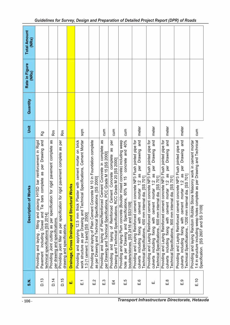
- 106 -
Guidelines for Survey, Design and Preparation of Detailed Project Report (DPR) of Roads
Transport Infrastructure Directorate, Hetauda
Gu
idelin
es f
or
Su
rvey
Wo
rks In
clu
din
g P
rep
ara
tio
n o
f D
eta
iled
Pro
ject
Rep
ort
(D
PR
) o
f R
oad
s
Tra
nsp
ort
In
frastr
uctu
re D
irecto
rate
, H
eta
ud
a
10
4
S.N
. D
esc
rip
tio
n o
f W
ork
s
Un
it
Qu
an
tity
R
ate
in
Fig
ure
(N
Rs)
To
tal
Am
ou
nt
(NR
s)
D.1
3
Pro
vid
ing a
nd l
ayi
ng ,
fitt
ing a
nd p
laci
ng H
YS
D b
ar
rein
forc
em
ent
in R
igid
P
ave
ment
in
clud
ing
Do
wel
and T
ie
bars
co
mple
te as
per
Dra
win
g a
nd
te
chnic
al s
pecifi
catio
ns
[SS
2014]
Kg
D.1
4
Pro
vid
ing J
oin
t cu
ttin
g a
s per
speci
ficatio
n f
or
rigid
pave
ment
com
ple
te a
s
per
dra
win
g a
nd s
peci
fications.
R
m
D.1
5
Pro
vid
ing
Join
t fil
ler
as
per
speci
ficatio
n f
or
rigid
pa
vem
ent
com
ple
te a
s pe
r dra
win
g a
nd s
peci
ficatio
ns.
R
m
E.
Dra
inag
e, C
ross D
rain
ag
e a
nd
Str
uctu
ral W
ork
s
E.1
P
rovi
din
g a
nd a
pp
lyin
g 1
2.5
mm
thic
k P
last
er
with
cem
ent
mort
ar
on b
rick
w
ork
str
uct
ure
as
per
Dra
win
g a
nd T
ech
nic
al
Specifi
catio
ns,
Cem
ent
Mort
ar
1:3
(1 c
em
ent: 3
sa
nd)
[SS
2500]
sqm
E.2
P
rovi
din
g a
nd
la
ying
of
Pla
in C
em
ent
Concr
ete
M 1
0 in F
ound
atio
n c
om
ple
te
as
per
Dra
win
g a
nd T
ech
nic
al S
peci
ficatio
ns.
[S
S 2
00
0]
E.3
P
rovi
din
g a
nd l
ayi
ng
of
Pla
in/R
ein
forc
ed C
em
ent
Co
ncr
ete
in c
om
ple
te a
s
per
Dra
win
g a
nd
Tech
nic
al S
peci
ficatio
ns,
PC
C G
rade M
15 [
SS
2000]
cum
E4
P
rovi
din
g
and
layi
ng
of
Rein
forc
ed
C
em
ent
Co
ncr
ete
co
mple
te
as
per
Dra
win
g a
nd T
ech
nic
al S
pe
cific
atio
ns,
RC
C G
rad
e M
20 [S
S 2
000
] cu
m
E.5
P
rovi
din
g a
nd la
ying
Plu
m c
oncr
ete
(B
ould
er
mix
ed c
oncr
ete
) in
clu
din
g w
ee
p
hole
as
per
Dra
win
g a
nd
S
peci
ficatio
ns,
6
0%
M
1
5 co
ncr
ete
an
d 40
%
bou
lders
/sto
nes,
[S
S 2
41
6 a
nd S
S310
9]
cum
E.6
P
rovi
din
g a
nd L
ayi
ng R
ein
forc
ed c
em
ent
concr
ete
NP
3 F
lush
join
ted p
ipe f
or
culv
ert
s in
cludin
g
fixin
g
with
ce
ment
mort
ar
1:2
as
per
Dra
win
g
and
T
ech
nic
al S
peci
ficatio
ns.
, 4
50 m
m in
tern
al d
ia. [S
S 7
01]
mete
r
E.
Pro
vid
ing a
nd L
ayi
ng R
ein
forc
ed c
em
ent
concr
ete
NP
3 F
lush
join
ted p
ipe f
or
culv
ert
s in
cludin
g
fixin
g
with
ce
ment
mort
ar
1:2
as
per
Dra
win
g
and
T
ech
nic
al S
peci
ficatio
ns.
, 6
00 m
m in
tern
al d
ia.
[SS
70
1]
mete
r
E.8
P
rovi
din
g a
nd L
ayi
ng R
ein
forc
ed c
em
ent
concr
ete
NP
3 F
lush
join
ted p
ipe f
or
culv
ert
s in
cludin
g
fixin
g
with
ce
ment
mort
ar
1:2
as
per
Dra
win
g
and
T
ech
nic
al S
peci
ficatio
ns.
, 9
00 m
m in
tern
al d
ia. [S
S 7
01]
mete
r
E.9
P
rovi
din
g a
nd L
ayi
ng R
ein
forc
ed c
em
ent
concr
ete
NP
3 F
lush
join
ted p
ipe f
or
culv
ert
s in
cludin
g
fixin
g
with
ce
ment
mort
ar
1:2
as
per
Dra
win
g
and
T
ech
nic
al S
peci
ficatio
ns.
, 1
200 m
m in
tern
al d
ia. [S
S 7
01]
mete
r
E.1
0
Pro
vid
ing a
nd l
ayi
ng R
an
dom
Rubble
Sto
ne M
aso
nry
work
in c
em
ent
mort
ar
1:4
in s
truct
ure
incl
udin
g w
eep h
ole
s co
mple
te a
s per
Dra
win
g a
nd T
ech
nic
al
Speci
ficatio
n. [
SS
26
07 a
nd S
S 3
109]
cum
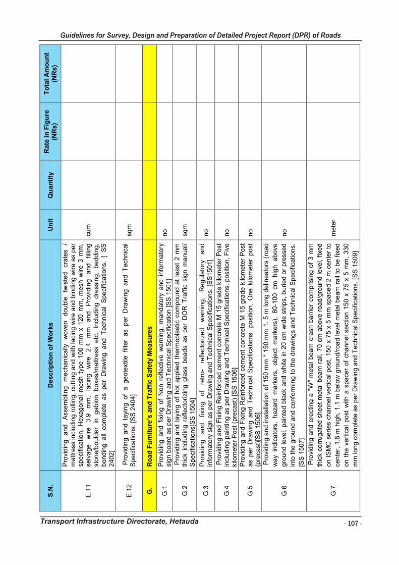
- 107 -
Guidelines for Survey, Design and Preparation of Detailed Project Report (DPR) of Roads
Transport Infrastructure Directorate, Hetauda
Gu
idelin
es f
or
Su
rvey
Wo
rks In
clu
din
g P
rep
ara
tio
n o
f D
eta
iled
Pro
ject
Rep
ort
(D
PR
) o
f R
oad
s
Tra
nsp
ort
In
frastr
uctu
re D
irecto
rate
, H
eta
ud
a
10
5
S.N
. D
esc
rip
tio
n o
f W
ork
s
Un
it
Qu
an
tity
R
ate
in
Fig
ure
(N
Rs)
To
tal
Am
ou
nt
(NR
s)
E.1
1
Pro
vid
ing
a
nd
A
ssem
blin
g
mech
anic
ally
w
ove
n
doub
le
twis
ted
cr
ate
s /
mattre
ss in
clud
ing r
olli
ng,
cuttin
g a
nd w
ith laci
ng w
ire a
nd b
ind
ing w
ire a
s per
speci
ficatio
n,
Hexa
go
na
l m
esh
typ
e 1
00 m
m x
120 m
m,
mesh
wir
e 3
mm
, se
lvage
wire
3.9
m
m,
laci
ng
wire
2.4
m
m
and
Pro
vid
ing
an
d
fillin
g
stone/b
ou
lder
in
ga
bio
n
boxe
s/m
attre
ss
etc
. In
cludin
g
dre
ssin
g,
be
ddin
g,
bond
ing a
ll co
mple
te as
per
Dra
win
g an
d T
ech
nic
al
Specifi
catio
ns.
[
SS
2402]
cum
E.1
2
Pro
vidin
g an
d la
yin
g of
a geote
xtile
fil
ter
as
per
Dra
win
g an
d T
ech
nic
al
Speci
ficatio
ns.
[S
S 2
404
] sq
m
G.
Ro
ad
Fu
rnit
ure
’s a
nd
Tra
ffic
Safe
ty M
easu
res
G.1
P
rovi
din
g a
nd f
ixin
g o
f N
on r
efle
ctiv
e w
arn
ing,
mandato
ry a
nd i
nfo
rmato
ry
sign b
oard
as
per
Dra
win
g a
nd T
ech
nic
al S
pecifi
catio
n [S
S 1
501]
no
G.2
P
rovi
din
g a
nd l
ayi
ng o
f ho
t ap
plie
d t
herm
opla
stic
co
mpound a
t le
ast
2 m
m
thic
k i
ncl
ud
ing r
efle
ctori
zing g
lass
be
ads
as p
er
DO
R T
raff
ic s
ign m
anual/
Speci
ficatio
ns[
SS
15
04]
sqm
G.3
P
rovi
din
g
and
fix
ing
of
retr
o-
refle
ctori
zed
warn
ing,
Re
gula
tory
an
d
info
rmato
ry s
ign a
s per
Dra
win
g a
nd T
ech
nic
al S
peci
fica
tions.
[S
S15
01]
no
G.4
P
rovi
din
g a
nd
Fix
ing R
ein
forc
ed c
em
ent
concr
ete
M 1
5 g
rade k
ilom
ete
r P
ost
in
clu
din
g p
ain
ting a
s per
Dra
win
g a
nd T
ech
nic
al S
peci
ficatio
ns.
posi
tion,
Fiv
e
kilo
mete
r P
ost
(pre
cast
) [S
S 1
506]
no
G.5
P
rovi
din
g a
nd F
ixin
g R
ein
forc
ed c
em
ent
concr
ete
M 1
5 g
rad
e k
ilom
ete
r P
ost
as
per
Dra
win
g a
nd T
ech
nic
al
Speci
ficatio
ns.
posi
tion,
One k
ilom
ete
r post
(p
reca
st)[
SS
150
6]
no
G.6
Pro
vidin
g a
nd inst
alla
tion o
f 150 m
m *
150 m
m 1
. 5 m
long d
elin
eato
rs (
road
wa
y in
dic
ato
rs,
ha
zard
m
ark
ers
, obje
ct m
ark
ers
), 80-1
00 cm
hig
h ab
ove
gro
un
d leve
l, pain
ted b
lack
an
d w
hite
in 2
0 c
m w
ide
str
ips,
burie
d o
r pre
ssed
into
the g
roun
d a
nd c
onfo
rmin
g t
o t
he d
raw
ings
and T
ech
nic
al S
peci
ficatio
ns.
[SS
15
07]
no
G.7
Pro
vidin
g a
nd e
rect
ing a
"W
" m
eta
l beam
cra
sh b
arr
ier
com
prisi
ng o
f 3 m
m
thic
k c
orr
ugate
d s
he
et
meta
l be
am
rail,
70
cm
above
road/g
roun
d leve
l, fix
ed
on I
SM
C s
eri
es
chan
ne
l ve
rtic
al post
, 15
0 x
75 x
5 m
m s
pace
d 2
m c
ente
r to
cente
r, 1
.8 m
hig
h,
1.1
m b
elo
w g
roun
d/r
oa
d leve
l m
eta
l be
am
rail
to b
e f
ixed
on t
he
vert
ica
l post
with
a s
pace
r of
cha
nne
l se
ctio
n 1
50
x 7
5 x
5 m
m,
330
mm
long c
om
ple
te a
s per
Dra
win
g a
nd T
ech
nic
al S
peci
ficatio
ns.
[S
S 1
509]
mete
r
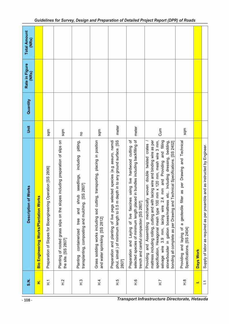
- 108 -
Guidelines for Survey, Design and Preparation of Detailed Project Report (DPR) of Roads
Transport Infrastructure Directorate, Hetauda
Gu
idelin
es f
or
Su
rvey
Wo
rks In
clu
din
g P
rep
ara
tio
n o
f D
eta
iled
Pro
ject
Rep
ort
(D
PR
) o
f R
oad
s
Tra
nsp
ort
In
frastr
uctu
re D
irecto
rate
, H
eta
ud
a
106
S.N
. D
esc
rip
tio
n o
f W
ork
s
Un
it
Qu
an
tity
R
ate
in
Fig
ure
(N
Rs)
To
tal
Am
ou
nt
(NR
s)
H.
Bio
En
gin
eeri
ng
Wo
rks/P
lan
tati
on
Wo
rks
H.1
P
repara
tion o
f S
lop
es
for
Bio
eng
ineeri
ng O
pera
tion [
SS
28
06]
sqm
H.2
P
lantin
g o
f ro
ote
d g
rass
slip
s on t
he s
lopes
incl
udin
g p
repara
tion o
f sl
ips
on
the s
ite. [S
S 2
807]
sqm
H.3
P
lantin
g
con
tain
eri
zed
tree
an
d
shru
b
seed
ling
s,
incl
ud
ing
pitt
ing
,
transp
lantin
g,
com
post
ing a
nd m
ulc
hin
g. [
SS
280
7]
no
H.4
G
rass
soddin
g w
ork
s in
clu
din
g s
od
cutt
ing,
transp
ort
ing,
pla
cin
g i
n p
osi
tion
and w
ate
r sp
rinklin
g
[SS
2812]
sqm
H.5
Pre
para
tion a
nd p
lantin
g o
f liv
e p
egs
sele
cted s
peci
es
(e.g
ass
uro
, nam
di
phu
l, si
mali
) of
min
imum
length
to 0
.5 m
depth
in t
o a
ny
gro
und s
urf
ace
. [S
S
2807]
mete
r
H.6
Pre
para
tion
and
La
ying
of
live
fa
scin
es
usi
ng
live
hard
wo
od
cuttin
g
of
sele
cted s
peci
es
of
min
imum
length
pla
ced in b
un
dle
s in
clu
din
g b
ack
fillin
g o
f
trench
an
d c
are
ful c
om
pact
ion [
SS
2807]
mete
r
H.7
Pro
vid
ing
a
nd
A
ssem
blin
g
mech
anic
ally
w
ove
n
doub
le
twis
ted
cr
ate
s /
mattre
ss in
clud
ing r
olli
ng,
cuttin
g a
nd w
ith laci
ng w
ire a
nd b
ind
ing w
ire a
s per
speci
ficatio
n,
Hexa
go
na
l m
esh
typ
e 1
00 m
m x
120 m
m,
mesh
wir
e 3
mm
,
selv
age
wire
3.9
m
m,
laci
ng
wire
2.4
m
m
and
Pro
vid
ing
an
d
fillin
g
stone/b
ou
lder
in g
abio
n b
oxe
s/m
attre
ss etc
.. In
clu
din
g dre
ssin
g,
bedd
ing
,
bondin
g a
ll co
mple
te a
s per
Dra
win
g a
nd T
ech
nic
al S
peci
ficatio
ns.
[S
S 2
402
]
Cum
H.8
P
rovi
din
g an
d la
yin
g of
a geote
xtile
fil
ter
as
per
Dra
win
g an
d T
ech
nic
al
Speci
ficatio
ns.
[S
S 2
404
] s
qm
I.
Da
ys W
ork
I.1
S
up
ply
of
labor
as
requ
ired a
s per
pre
am
ble
and
as
inst
ruct
ed b
y E
ng
ineer.
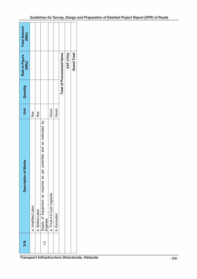
- 109 -
Guidelines for Survey, Design and Preparation of Detailed Project Report (DPR) of Roads
Transport Infrastructure Directorate, Hetauda
Gu
idelin
es f
or
Su
rvey
Wo
rks In
clu
din
g P
rep
ara
tio
n o
f D
eta
iled
Pro
ject
Rep
ort
(D
PR
) o
f R
oad
s
Tra
nsp
ort
In
frastr
uctu
re D
irecto
rate
, H
eta
ud
a
107
S.N
. D
esc
rip
tio
n o
f W
ork
s
Un
it
Qu
an
tity
R
ate
in
Fig
ure
(N
Rs)
To
tal
Am
ou
nt
(NR
s)
a. U
nsk
illed L
abor
Nos
b. S
kill
ed L
ab
or
Nos
I.2
S
up
ply
of
Equ
ipm
ent
as
requ
ired as
per
pre
am
ble
and as
inst
ruct
ed b
y E
ng
ineer
a. T
ruck
-4.6
Cum
Capaci
ty
Hours
b. E
xca
vato
r H
ours
To
tal o
f P
rocu
rem
en
t It
em
s
VA
T (
13
%)
Gra
nd
To
tal
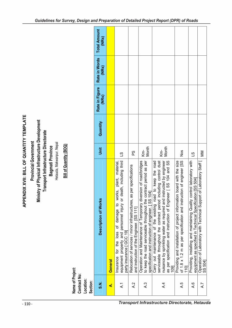
- 110 -
Guidelines for Survey, Design and Preparation of Detailed Project Report (DPR) of Roads
Transport Infrastructure Directorate, Hetauda
Gu
idelin
es f
or
Su
rvey
Wo
rks In
clu
din
g P
rep
ara
tio
n o
f D
eta
iled
Pro
ject
Rep
ort
(D
PR
) o
f R
oad
s
Tra
nsp
ort
In
frastr
uctu
re D
irecto
rate
, H
eta
ud
a
10
8
AP
PE
ND
IX X
VII
: B
ILL
OF
QU
AN
TIT
Y T
EM
PL
AT
E
Pro
vinc
ial G
over
nmen
t
Min
istr
y of
Phy
sica
l Inf
rast
ruct
ure
Dev
elop
men
t
Tran
spor
t Inf
rast
ruct
ure
Dir
ecto
rate
Bag
mat
i Pro
vinc
e
Het
auda
, Mak
wan
pur,
Nep
al
Bill
of Q
uant
ity (B
OQ
)
Nam
e of
Pro
ject
:
Con
trac
t No:
Loca
tion:
Sec
tion:
S.N
. D
esc
rip
tio
n o
f W
ork
s
Un
it
Qu
an
tity
R
ate
in
Fig
ure
(N
Rs)
Rate
in
Wo
rds
(N
Rs)
To
tal
Am
ou
nt
(NR
s)
A.
Gen
era
l
A.1
In
sura
nce
fo
r th
e
loss
of
dam
age
to
work
s,
pla
nt,
mate
rial,
equ
ipm
ent
pro
pert
y a
nd p
ers
onnel
inju
ry o
r d
eath
, in
clud
ing t
hir
d
part
y in
sura
nce
[ G
CC
19]
LS
A.2
R
elo
catio
n o
f se
rvic
es
/ m
inor
infr
ast
ruct
ure
s, a
s per
speci
ficatio
ns
and in
stru
ctio
n o
f th
e E
ng
ineer.
[S
S 1
11]
PS
A.3
O
pera
tion a
nd M
ain
tena
nce
of
Tem
pora
ry d
ivers
ion o
f ro
ad/b
ridges
to k
eep t
he r
oad s
erv
iceab
le t
hro
ugh
out
the c
ontr
act
period a
s per
speci
ficatio
n a
nd in
stru
ctio
n o
f engin
eer.
[ S
S 1
04]
Km
-M
onth
A.4
Carr
y out
main
tenance
o
f th
e
exi
stin
g
roa
d
to
keep
the
road
se
rvic
ea
ble
th
roug
hout
the
contr
act
peri
od
in
clud
ing
contr
ol
dust
nuis
ance
by
sprinkl
ing w
ate
r as
requ
ired
an
d i
nst
ruct
ed b
y e
ngin
eer
as
per
speci
ficatio
n a
nd i
nst
ruct
ion o
f E
ng
ineer
[ S
S 1
04 a
nd S
S
109]
Km
-M
onth
A.5
P
rovi
din
g a
nd i
nst
alla
tion o
f pro
ject
info
rmatio
n b
oard
with
the s
ize
of
1.8
x 1
.2 m
as
per
speci
ficatio
n a
nd i
nst
ruct
ion o
f engin
eer
[SS
110]
Nos
A.6
P
rovi
din
g,
inst
alli
ng a
nd m
ain
tain
ing Q
ua
lity
contr
ol
labora
tory
with
equ
ipm
ent as
speci
fied
in T
ech
nic
al S
peci
ficatio
n [S
S 5
04]
LS
A.7
O
pera
tion
of
La
bora
tory
with
Tech
nic
al S
up
port
of
La
bora
tory
Sta
ff [
S
S 5
04
] M
M
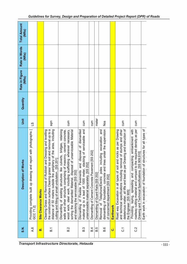
- 111 -
Guidelines for Survey, Design and Preparation of Detailed Project Report (DPR) of Roads
Transport Infrastructure Directorate, Hetauda
Gu
idelin
es f
or
Su
rvey
Wo
rks In
clu
din
g P
rep
ara
tio
n o
f D
eta
iled
Pro
ject
Rep
ort
(D
PR
) o
f R
oad
s
Tra
nsp
ort
In
frastr
uctu
re D
irecto
rate
, H
eta
ud
a
10
9
S.N
. D
esc
rip
tio
n o
f W
ork
s
Un
it
Qu
an
tity
R
ate
in
Fig
ure
(N
Rs)
Rate
in
Wo
rds
(N
Rs)
To
tal
Am
ou
nt
(NR
s)
A.8
P
rovi
din
g c
om
ple
te b
uilt
up d
raw
ing a
nd r
eport
with
photo
gra
phs
[ G
CC
71.2
] LS
B.
Sit
e C
leara
nce
Wo
rks
B.1
Cle
ari
ng
Gra
ss a
nd R
em
ova
l of
Rub
bis
h a
nd
Dre
ssin
g a
nd l
eve
lling
th
e c
onst
ruct
ion s
urf
ace
Cle
arin
g g
rass
/ to
p s
oil
and r
em
ova
l up t
o a
dis
tance
of
50 m
ete
rs o
uts
ide t
he p
eri
phery
of
the a
rea,
incl
udin
g
cuttin
g a
nd f
illin
g o
f sm
all
undu
latio
n.,
[S
S 2
01]
sqm
B.2
Dis
mantli
ng
of
exi
stin
g
stru
cture
s lik
e
culv
ert
s,
bri
dges,
re
tain
ing
w
alls
and o
ther
stru
cture
com
prisi
ng o
f m
aso
nry
, ce
ment
concr
ete
, w
ood w
ork
, st
eel
work
, in
cludin
g s
caff
old
ing w
here
ver
nece
ssary
, so
rtin
g t
he d
ism
antle
d M
ate
rial,
dis
posa
l of
unse
rvic
eable
Mate
ria
l and s
tack
ing t
he s
erv
icea
ble
[S
S 2
02]
cum
B.3
D
ism
antli
ng
of
Fle
xib
le
Pave
ments
and
dis
posa
l of
dis
mantle
d
mate
rial
up
to a
lea
d o
f 1
000 m
ete
r, s
tack
ing o
f se
rvic
ea
ble
an
d
unse
rvic
eab
le m
ate
rial s
ep
ara
tely
. [S
S 2
02]
cum
B.4
D
ism
antli
ng
of
Cem
ent C
on
crete
Pa
vem
ent [S
S 2
02
] cu
m
B.5
D
ism
antli
ng
of
Guard
Rails
[S
S 2
02]
mete
r
B.6
R
em
ova
l of
Tele
ph
one/E
lect
ric
pole
s in
clud
ing
exc
ava
tion
and
dis
mantli
ng o
f fo
undatio
n,
concr
ete
an
d l
ines
und
er
the s
uperv
isio
n
of
conce
rned d
epart
ment [S
S 2
02
] N
os
C.
Eart
hw
ork
C.1
Road w
ay
Exc
ava
tion i
n a
ll ty
pes
of
soil
and r
ock
s as
per
Dra
win
g
and t
ech
nic
al
speci
ficatio
ns
incl
ud
ing r
em
ova
l of
stum
ps
and o
ther
dele
teri
ous
matter,
all
lifts
and le
ad a
s per
Dra
win
g a
nd
inst
ruct
ion
of
the E
ng
ineer.
[S
S 9
05
]
cum
C.2
P
rovi
din
g,
layi
ng,
spre
adin
g
an
d
com
pact
ing
em
bankm
ent
with
ro
ad
wa
y cu
ttin
g m
ate
rial a
nd c
om
pact
to t
he r
equir
ed
densi
ty a
s per
Dra
win
g a
nd T
ech
nic
al S
pe
cific
atio
ns.
[S
S 9
09,9
10]
cum
C.3
Eart
h w
ork
in e
xcava
tion o
f fo
undatio
n o
f st
ruct
ure
s fo
r all
typ
es
of
soil
and
rock
s,
incl
udin
g
const
ruct
ion
of
shori
ng
and
bra
cing,
rem
ova
l of
stum
ps
and o
ther
dele
teri
ous
matter
an
d b
ack
fillin
g w
ith
appro
ved M
ate
ria
l as
per
Dra
win
g a
nd T
ech
nic
al S
peci
ficatio
ns.
[S
S
907]
cum
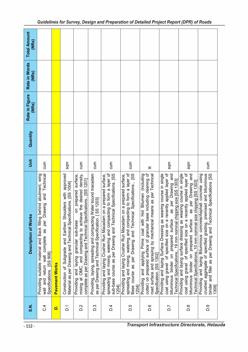
- 112 -
Guidelines for Survey, Design and Preparation of Detailed Project Report (DPR) of Roads
Transport Infrastructure Directorate, Hetauda
Gu
idelin
es f
or
Su
rvey
Wo
rks In
clu
din
g P
rep
ara
tio
n o
f D
eta
iled
Pro
ject
Rep
ort
(D
PR
) o
f R
oad
s
Tra
nsp
ort
In
frastr
uctu
re D
irecto
rate
, H
eta
ud
a
11
0
S.N
. D
esc
rip
tio
n o
f W
ork
s
Un
it
Qu
an
tity
R
ate
in
Fig
ure
(N
Rs)
Rate
in
Wo
rds
(N
Rs)
To
tal
Am
ou
nt
(NR
s)
C.4
P
rovi
din
g s
uita
ble
mate
rial
and B
ack
fill
ing b
ehin
d a
butm
ent, w
ing
wall
an
d
retu
rn
wall
com
ple
te
as
per
Dra
win
g
and
Tech
nic
al
Speci
ficatio
ns.
[S
S 9
08]
cum
D.
Pav
em
en
t W
ork
s
D.1
C
onst
ruct
ion
of
Sub
gra
de
and
E
art
he
n
Sho
uld
ers
w
ith
ap
pro
ved
Mate
rial a
s per
Dra
win
g a
nd T
ech
nic
al S
peci
ficatio
ns.
[S
S 1
004]
sqm
D.2
P
rovi
din
g
and
layi
ng
gra
nula
r su
b-b
ase
on
pre
pare
d
surf
ace
, m
ixin
g at
OM
C,
and co
mpact
ing to
ach
ieve
th
e de
sire
d de
nsi
ty,
com
ple
te a
s per
Dra
win
g a
nd T
ech
nic
al S
peci
ficatio
ns.
, [S
S 1
201]
cum
D.3
P
rovi
din
g,
layi
ng,
spre
adin
g a
nd c
om
pact
ing W
ate
r bound m
aca
dam
as
per
Dra
win
g a
nd T
ech
nic
al S
peci
ficatio
n.
[ S
S 1
20
3]
cum
D.4
Pro
vid
ing
an
d la
ying C
rush
er
Run M
aca
dam
on a
pre
pare
d s
urf
ace
, sp
readin
g a
nd m
ixin
g,
wate
ring a
nd c
om
pact
ing t
o f
orm
a l
aye
r of
sub
-base
cours
e a
s per
Dra
win
g a
nd T
ech
nic
al
Speci
ficatio
ns.
[S
S
1204]
cum
D.5
Pro
vid
ing
an
d la
ying C
rush
er
Run M
aca
dam
on a
pre
pare
d s
urf
ace
, sp
readin
g a
nd m
ixin
g,
wate
ring a
nd c
om
pact
ing t
o f
orm
a l
aye
r of
Base
co
urs
e
as
per
Dra
win
g
and
Tech
nic
al
Speci
ficatio
ns.
, [S
S
1204]
cum
D.6
Pro
vid
ing
a
nd
ap
ply
ing
Prim
e
coat
with
H
ot
Bitu
men
(incl
udin
g
cutter)
on p
rep
are
d s
urf
ace
of
gra
nula
r base
incl
ud
ing c
lea
nin
g o
f ro
ad s
urf
ace
and s
pra
yin
g b
y m
ech
anic
al
means
as
per
Tech
nic
al
Speci
ficatio
n. [S
S 1
30
2]
lit
D.7
Pro
vid
ing
an
d l
ayi
ng S
urf
ace
Dre
ssin
g a
s w
earin
g c
ours
e i
n s
ing
le
coat
usi
ng g
rave
l o
f sp
eci
fied s
ize o
n a
rece
ntly
ap
plie
d l
aye
r of
bitu
min
ous
bin
der
on
pre
pare
d
surf
ace
as
per
Dra
win
g
an
d
Tech
nic
al S
peci
ficatio
ns.
, 1
9 m
m n
om
inal c
hip
pin
g s
ize [S
S 1
303
]
sqm
D.8
Pro
vid
ing
an
d l
ayi
ng s
urf
ace
dre
ssin
g a
s w
eari
ng c
ours
e i
n s
ingle
co
at
usi
ng g
rave
l o
f sp
eci
fied s
ize o
n a
rece
ntly
ap
plie
d l
aye
r of
bitu
min
ous
bin
der
on
pre
pare
d
surf
ace
as
per
Dra
win
g
an
d
Tech
nic
al S
peci
ficatio
ns.
,10 m
m n
om
inal s
ize c
hip
pin
g [S
S 1
303
]
sqm
D.9
Pro
vid
ing
an
d la
ying
Bitu
min
ous
concr
ete
/Asp
halt
concr
ete
usi
ng
cr
ush
ed a
ggre
gate
of
spe
cifie
d g
radin
g,
pre
mix
ed a
nd b
itum
inous
bin
der
an
d f
iller
as
per
Dra
win
g a
nd T
ech
nic
al
Speci
ficatio
ns
[SS
1309]
cum
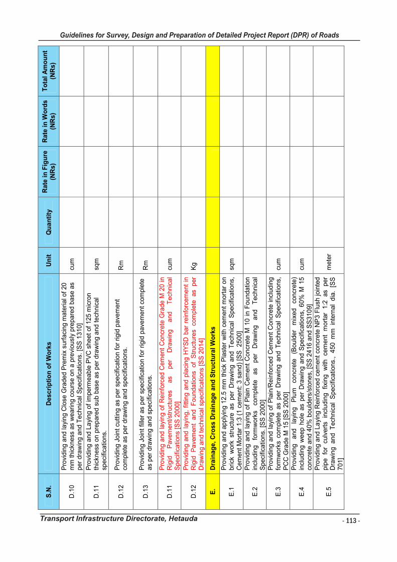
- 113 -
Guidelines for Survey, Design and Preparation of Detailed Project Report (DPR) of Roads
Transport Infrastructure Directorate, Hetauda
Gu
idelin
es f
or
Su
rvey
Wo
rks In
clu
din
g P
rep
ara
tio
n o
f D
eta
iled
Pro
ject
Rep
ort
(D
PR
) o
f R
oad
s
Tra
nsp
ort
In
frastr
uctu
re D
irecto
rate
, H
eta
ud
a
11
1
S.N
. D
esc
rip
tio
n o
f W
ork
s
Un
it
Qu
an
tity
R
ate
in
Fig
ure
(N
Rs)
Rate
in
Wo
rds
(N
Rs)
To
tal
Am
ou
nt
(NR
s)
D.1
0
Pro
vid
ing
an
d la
yin
g C
lose
Gra
ded P
rem
ix s
urf
aci
ng m
ate
rial o
f 20
m
m thic
kness
as
we
arin
g c
ours
e o
n a
pre
viousl
y pre
pare
d b
ase
as
per
dra
win
g a
nd T
ech
nic
al S
peci
ficatio
ns.
[S
S 1
310
] cu
m
D.1
1
Pro
vid
ing
an
d L
ayi
ng
of
imperm
eable
PV
C s
heet
of
125 m
icro
n
thic
kness
on p
rep
are
d s
ub b
ase
as
per
dra
win
g a
nd te
chnic
al
speci
ficatio
ns.
sq
m
D.1
2
Pro
vid
ing
Join
t cu
ttin
g a
s p
er
speci
ficatio
n f
or
rig
id p
ave
ment
com
ple
te a
s per
dra
win
g a
nd s
peci
ficatio
ns.
R
m
D.1
3
Pro
vid
ing
Join
t fil
ler
as
per
speci
ficatio
n f
or
rigid
pave
ment co
mple
te
as
per
dra
win
g a
nd s
peci
ficatio
ns.
R
m
D.1
1
Pro
vid
ing a
nd la
yin
g o
f R
ein
forc
ed C
em
ent
Concr
ete
Gra
de M
20 in
Rig
id
Pave
ment/st
ruct
ure
s as
per
Dra
win
g
and
Tech
nic
al
Speci
ficatio
ns
[SS
2000]
cum
D.1
2
Pro
vid
ing a
nd l
ayi
ng,
fittin
g a
nd p
laci
ng H
YS
D b
ar
rein
forc
em
ent
in
Rig
id
Pave
ment
and
Fou
ndatio
ns
of
Str
uct
ure
s co
mple
te
as
per
Dra
win
g a
nd t
ech
nic
al s
peci
ficatio
ns
[SS
2014]
Kg
E.
Dra
inag
e, C
ross D
rain
ag
e a
nd
Str
uctu
ral W
ork
s
E.1
P
rovi
din
g a
nd a
pp
lyin
g 1
2.5
mm
thic
k P
last
er
with
cem
ent
mort
ar
on
brick
work
str
uct
ure
as
pe
r D
raw
ing
an
d T
ech
nic
al
Speci
ficatio
ns,
C
em
ent M
ort
ar
1:3
(1 c
em
ent: 3
sa
nd)
[SS
25
00]
sqm
E.2
P
rovi
din
g a
nd l
ayi
ng o
f P
lain
Cem
ent
Concr
ete
M 1
0 i
n F
ou
nda
tion
incl
udin
g
form
work
s co
mple
te
as
per
Dra
win
g
and
Tech
nic
al
Speci
ficatio
ns.
[S
S 2
000
]
E.3
P
rovi
din
g a
nd la
ying o
f P
lain
/Re
info
rced C
em
ent
Concr
ete
incl
ud
ing
fo
rmw
ork
s co
mple
te a
s p
er
Dra
win
g a
nd T
ech
nic
al
Speci
ficatio
ns,
P
CC
Gra
de M
15 [
SS
2000
] cu
m
E.4
P
rovi
din
g
and
layi
ng
Plu
m
concr
ete
(B
ou
lder
mix
ed
concr
ete
) in
clu
din
g w
eep h
ole
as
pe
r D
raw
ing a
nd S
peci
ficatio
ns,
60%
M 1
5
concr
ete
an
d 4
0%
bou
lders
/sto
nes,
[S
S 2
416 a
nd S
S3
109]
cum
E.5
Pro
vid
ing
an
d L
ayi
ng R
ein
forc
ed c
em
ent
concr
ete
NP
3 F
lush
join
ted
pip
e
for
culv
ert
s in
clu
din
g
fixin
g
with
ce
ment
mort
ar
1:2
as
per
Dra
win
g an
d T
ech
nic
al
Speci
ficatio
ns.
, 45
0 m
m in
tern
al
dia
. [S
S
701]
mete
r
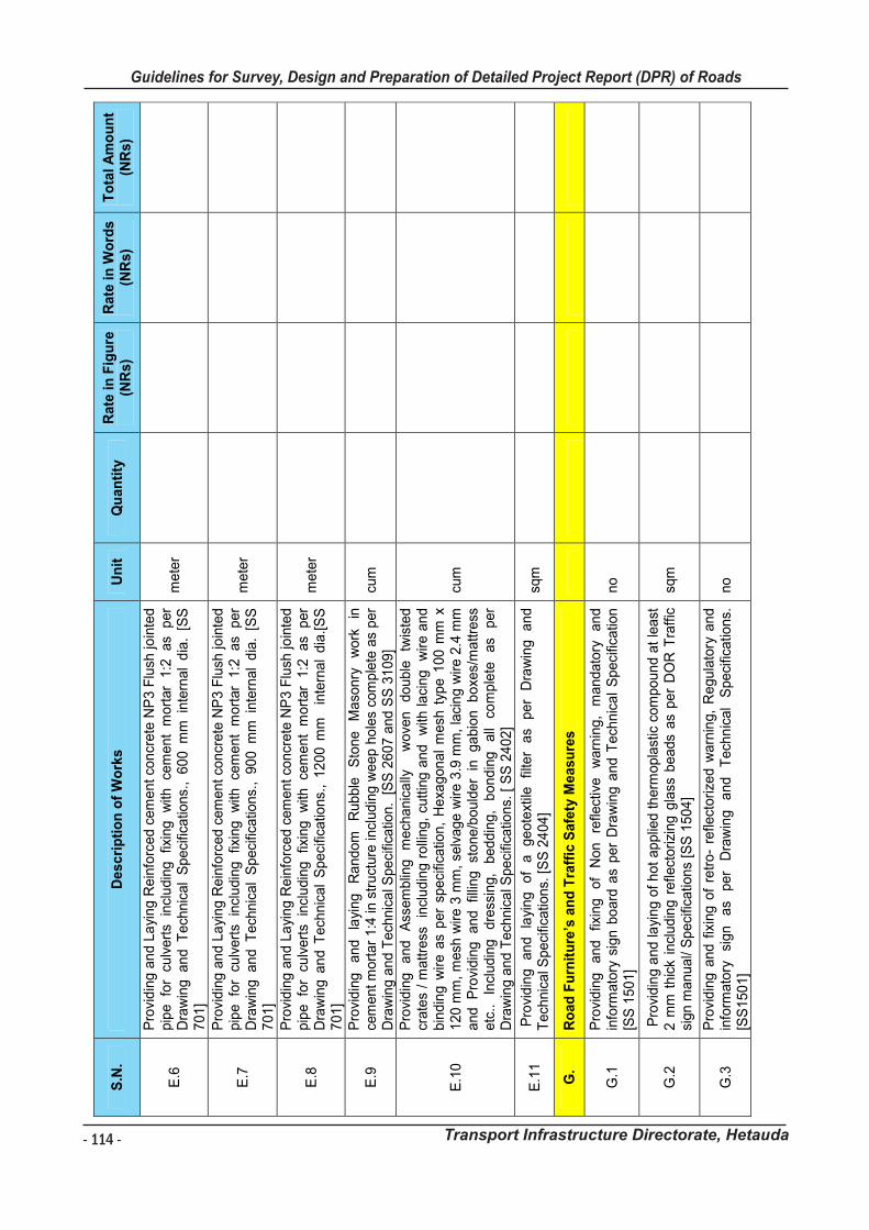
- 114 -
Guidelines for Survey, Design and Preparation of Detailed Project Report (DPR) of Roads
Transport Infrastructure Directorate, Hetauda
Gu
ide
lin
es
fo
r S
urv
ey
Wo
rks I
nc
lud
ing
Pre
pa
rati
on
of
De
tail
ed
Pro
jec
t R
ep
ort
(D
PR
) o
f R
oa
ds
Tra
ns
po
rt I
nfr
as
tru
ctu
re D
irec
tora
te,
He
tau
da
112
S.N
. D
es
cri
pti
on
of
Wo
rks
U
nit
Q
ua
nti
ty
Ra
te i
n F
igu
re
(NR
s)
Ra
te i
n W
ord
s
(NR
s)
To
tal
Am
ou
nt
(NR
s)
E.6
Pro
vid
ing
an
d L
ayi
ng
Re
info
rce
d c
em
en
t co
ncr
ete
NP
3 F
lush
join
ted
p
ipe
fo
r cu
lve
rts
incl
ud
ing
fix
ing
w
ith
cem
en
t m
ort
ar
1:2
a
s p
er
Dra
win
g a
nd
T
ech
nic
al
Sp
eci
fica
tion
s.,
60
0 m
m in
tern
al
dia
. [S
S
70
1]
me
ter
E.7
Pro
vid
ing
an
d L
ayi
ng
Re
info
rce
d c
em
en
t co
ncr
ete
NP
3 F
lush
join
ted
p
ipe
fo
r cu
lve
rts
incl
ud
ing
fix
ing
w
ith
cem
en
t m
ort
ar
1:2
a
s p
er
Dra
win
g a
nd
T
ech
nic
al
Sp
eci
fica
tion
s.,
90
0 m
m in
tern
al
dia
. [S
S
70
1]
me
ter
E.8
Pro
vid
ing
an
d L
ayi
ng
Re
info
rce
d c
em
en
t co
ncr
ete
NP
3 F
lush
join
ted
p
ipe
fo
r cu
lve
rts
incl
ud
ing
fix
ing
w
ith
cem
en
t m
ort
ar
1:2
a
s p
er
Dra
win
g a
nd
Te
chn
ica
l S
pe
cific
atio
ns.
, 1
20
0 m
m
inte
rna
l d
ia.[
SS
7
01
]
me
ter
E.9
P
rovi
din
g
an
d
layi
ng
R
an
do
m
Ru
bb
le
Sto
ne
M
aso
nry
w
ork
in
ce
me
nt
mo
rta
r 1
:4 in
str
uct
ure
incl
ud
ing
we
ep h
ole
s co
mp
lete
as
pe
r D
raw
ing
an
d T
ech
nic
al S
pe
cific
atio
n.
[S
S 2
60
7 a
nd
SS
31
09
] cu
m
E.1
0
Pro
vid
ing
a
nd
A
sse
mb
ling
m
ech
an
ica
lly
w
ove
n
do
ub
le
twis
ted
cr
ate
s /
ma
ttre
ss
incl
ud
ing
ro
llin
g,
cutt
ing
an
d
with
la
cin
g
wire
an
d
bin
din
g w
ire
as
pe
r sp
eci
fica
tion
, H
exa
go
na
l m
esh
typ
e 1
00
mm
x
12
0 m
m,
mesh
wire
3 m
m,
selv
ag
e w
ire
3.9
mm
, la
cin
g w
ire
2.4
mm
a
nd
P
rovi
din
g
an
d
fillin
g
sto
ne
/bo
uld
er
in
ga
bio
n
bo
xes/
ma
ttre
ss
etc
..
Incl
ud
ing
d
ress
ing
, b
ed
din
g,
bo
nd
ing
a
ll co
mp
lete
a
s p
er
Dra
win
g a
nd
Te
chn
ica
l Sp
eci
fica
tion
s. [
SS
24
02
]
cum
E.1
1
Pro
vid
ing
a
nd
la
yin
g
of
a
ge
ote
xtile
fil
ter
as
pe
r D
raw
ing
a
nd
T
ech
nic
al S
pe
cific
atio
ns.
[S
S 2
40
4]
sqm
G.
Ro
ad
Fu
rnit
ure
’s a
nd
Tra
ffic
Sa
fety
Me
as
ure
s
G.1
P
rovi
din
g
an
d
fixin
g
of
No
n
refle
ctiv
e
wa
rnin
g,
ma
nd
ato
ry
an
d
info
rma
tory
sig
n b
oa
rd a
s p
er
Dra
win
g a
nd
Te
chn
ica
l S
pe
cific
atio
n
[SS
15
01
] n
o
G.2
P
rovi
din
g a
nd
layi
ng
of
ho
t a
pp
lied
th
erm
op
last
ic c
om
po
un
d a
t le
ast
2
mm
th
ick
incl
ud
ing
re
flect
ori
zin
g g
lass
be
ads
as
pe
r D
OR
Tra
ffic
si
gn
ma
nu
al/
Sp
eci
fica
tion
s [S
S 1
50
4]
sqm
G.3
P
rovi
din
g a
nd
fix
ing
of
retr
o-
refle
cto
rize
d w
arn
ing
, R
eg
ula
tory
an
d
info
rma
tory
si
gn
a
s p
er
Dra
win
g
an
d
Te
chn
ica
l S
pe
cific
atio
ns.
[S
S1
50
1]
no
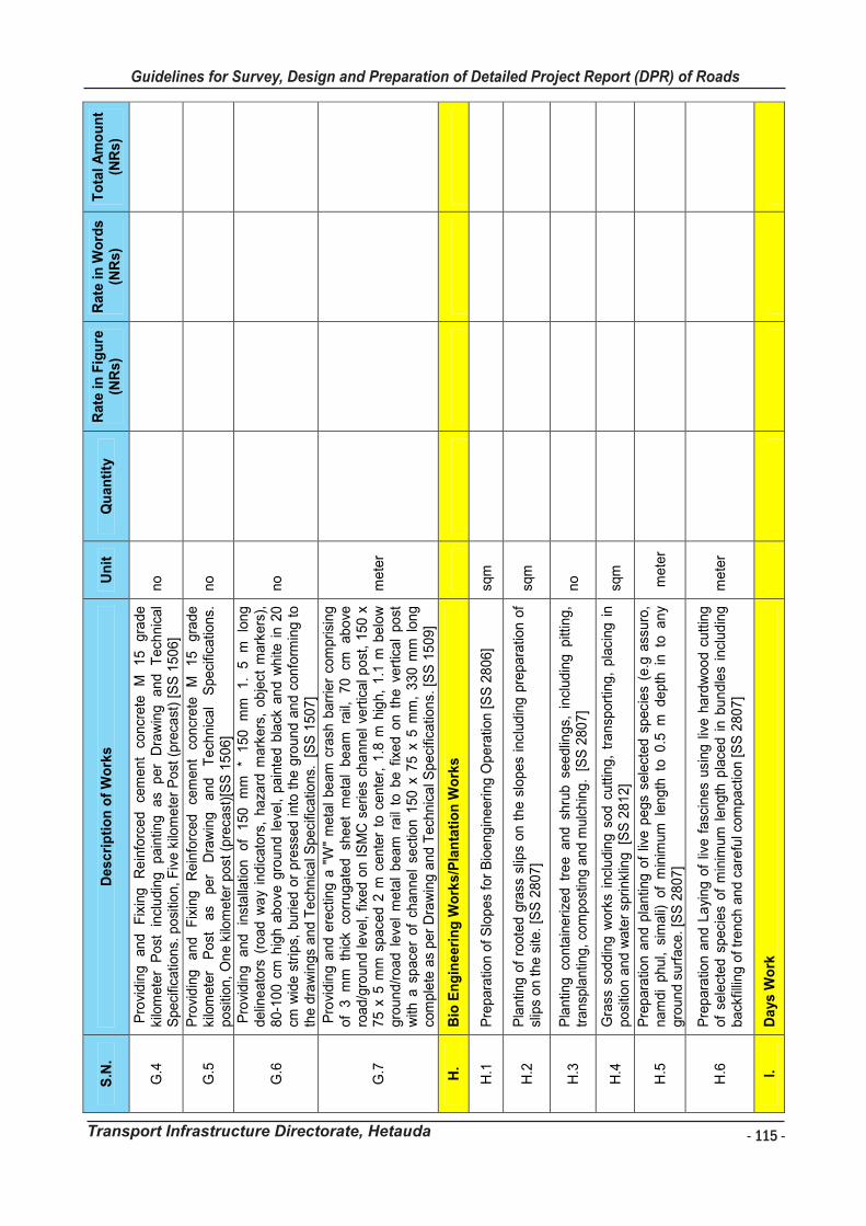
- 115 -
Guidelines for Survey, Design and Preparation of Detailed Project Report (DPR) of Roads
Transport Infrastructure Directorate, Hetauda
Gu
ide
lin
es
fo
r S
urv
ey
Wo
rks I
nc
lud
ing
Pre
pa
rati
on
of
De
tail
ed
Pro
jec
t R
ep
ort
(D
PR
) o
f R
oa
ds
Tra
ns
po
rt I
nfr
as
tru
ctu
re D
irec
tora
te,
He
tau
da
113
S.N
. D
es
cri
pti
on
of
Wo
rks
U
nit
Q
ua
nti
ty
Ra
te i
n F
igu
re
(NR
s)
Ra
te i
n W
ord
s
(NR
s)
To
tal
Am
ou
nt
(NR
s)
G.4
P
rovi
din
g
an
d
Fix
ing
R
ein
forc
ed
ce
me
nt
con
cre
te
M
15
g
rad
e
kilo
me
ter
Po
st
incl
ud
ing
p
ain
ting
a
s p
er
Dra
win
g
an
d
Te
chn
ica
l S
pe
cific
atio
ns.
po
sitio
n,
Fiv
e k
ilom
ete
r P
ost
(p
reca
st)
[SS
15
06
] n
o
G.5
P
rovi
din
g
an
d
Fix
ing
R
ein
forc
ed
ce
me
nt
con
cre
te
M
15
g
rad
e
kilo
me
ter
Po
st
as
pe
r D
raw
ing
a
nd
T
ech
nic
al
Spe
cific
atio
ns.
p
osi
tion
, O
ne
kilo
me
ter
po
st (
pre
cast
)[S
S 1
50
6]
no
G.6
Pro
vid
ing
a
nd
in
sta
llatio
n
of
15
0
mm
*
15
0
mm
1
. 5
m
lo
ng
d
elin
ea
tors
(ro
ad
wa
y in
dic
ato
rs,
ha
zard
ma
rke
rs,
ob
ject
ma
rke
rs),
8
0-1
00
cm
hig
h a
bo
ve g
rou
nd
le
vel,
pa
inte
d b
lack
an
d w
hite
in 2
0
cm w
ide
str
ips,
bu
rie
d o
r p
ress
ed
into
th
e g
rou
nd
an
d c
on
form
ing
to
th
e d
raw
ing
s a
nd
Te
chn
ica
l Spe
cific
atio
ns.
[S
S 1
50
7]
no
G.7
Pro
vid
ing
an
d e
rect
ing
a "
W"
me
tal
be
am
cra
sh b
arr
ier
com
prisi
ng
o
f 3
m
m
thic
k co
rru
ga
ted
sh
ee
t m
eta
l b
ea
m
rail,
7
0
cm
ab
ove
ro
ad
/gro
un
d le
vel,
fixe
d o
n I
SM
C s
eri
es
cha
nn
el ve
rtic
al p
ost
, 1
50
x
75
x 5
mm
sp
ace
d 2
m c
en
ter
to c
en
ter,
1.8
m h
igh
, 1
.1 m
be
low
g
rou
nd
/ro
ad
le
vel
me
tal
be
am
ra
il to
be
fix
ed
on
th
e v
ert
ica
l p
ost
w
ith a
sp
ace
r o
f ch
an
ne
l se
ctio
n 1
50
x 7
5 x
5 m
m,
33
0 m
m l
on
g
com
ple
te a
s p
er
Dra
win
g a
nd
Te
chn
ica
l Sp
eci
fica
tion
s. [
SS
15
09
]
me
ter
H.
Bio
En
gin
ee
rin
g W
ork
s/P
lan
tati
on
Wo
rks
H.1
P
rep
ara
tion
of
Slo
pe
s fo
r B
ioe
ng
ine
eri
ng
Op
era
tion
[S
S 2
80
6]
sqm
H.2
P
lan
ting
of
roo
ted
gra
ss s
lips
on
th
e s
lop
es
incl
ud
ing
pre
pa
ratio
n o
f sl
ips
on
th
e s
ite.
[SS
28
07
] sq
m
H.3
P
lan
ting
co
nta
ine
rize
d t
ree a
nd
sh
rub
se
ed
ling
s, i
ncl
ud
ing
pitt
ing
, tr
an
spla
ntin
g,
com
po
stin
g a
nd
mu
lch
ing
. [
SS
28
07
] n
o
H.4
G
rass
so
dd
ing
wo
rks
incl
ud
ing
so
d c
utt
ing
, tr
an
spo
rtin
g,
pla
cing
in
po
sitio
n a
nd
wa
ter
sprin
klin
g [S
S 2
81
2]
sqm
H.5
P
rep
ara
tion
an
d p
lan
ting
of
live
pe
gs
sele
cte
d s
pe
cie
s (e
.g a
ssu
ro,
na
md
i p
hu
l, si
ma
li) o
f m
inim
um
len
gth
to
0.5
m d
ep
th in
to
an
y g
rou
nd
su
rfa
ce.
[SS
28
07
] m
ete
r
H.6
P
rep
ara
tion
an
d L
ayi
ng
of
live f
asc
ine
s u
sing
liv
e h
ard
wo
od
cu
ttin
g
of
sele
cte
d s
pe
cies
of
min
imum
len
gth
pla
ced
in b
un
dle
s in
clu
din
g
ba
ckfil
ling
of
tre
nch
an
d c
are
ful c
om
pa
ctio
n [
SS
28
07
] m
ete
r
I.
Da
ys
Wo
rk
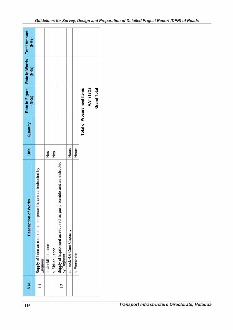
- 116 -
Guidelines for Survey, Design and Preparation of Detailed Project Report (DPR) of Roads
Transport Infrastructure Directorate, Hetauda
Gu
ide
lin
es
fo
r S
urv
ey
Wo
rks I
nc
lud
ing
Pre
pa
rati
on
of
De
tail
ed
Pro
jec
t R
ep
ort
(D
PR
) o
f R
oa
ds
Tra
ns
po
rt I
nfr
as
tru
ctu
re D
irec
tora
te,
He
tau
da
11
4
S.N
. D
es
cri
pti
on
of
Wo
rks
U
nit
Q
ua
nti
ty
Ra
te i
n F
igu
re
(NR
s)
Ra
te i
n W
ord
s
(NR
s)
To
tal
Am
ou
nt
(NR
s)
I.1
S
up
ply
of
lab
or
as
req
uire
d a
s p
er
pre
am
ble
and
as
inst
ruct
ed
by
Eng
ine
er.
a
. U
nsk
ille
d L
ab
or
No
s
b
. S
kille
d L
ab
or
No
s
I.2
S
up
ply
of
Eq
uip
me
nt
as
req
uire
d a
s p
er
pre
am
ble
an
d a
s in
stru
cte
d
by
Eng
ine
er
a
. T
ruck
-4.6
Cum
Ca
pa
city
H
ou
rs
b
. E
xca
vato
r H
ou
rs
To
tal
of
Pro
cu
rem
en
t It
em
s
VA
T (
13
%)
Gra
nd
To
tal
Guidelines for Survey Works Including Preparation of Detailed Project Report (DPR) of Roads
Transport Infrastructure Directorate, Hetauda
APPENDIX XVIII: TERM OF REFERENCE FOR DETAILED ENGINEERING SURVEY AND
DESIGN OF ROADS
1.0 BACKGROUND
The Ministry of Physical Infrastructure Development/ Transport Infrastructure Directorate,
Bagmati Province, Hetauda (herein after referred as "the Client"), intends to utilize services of
engineering consulting firms well experienced in the fields of survey and design of roads and
its associated structures, environment aspects etc. (herein after referred to as the “Consultant”)
for providing engineering consulting services for detailed project report preparation of proposed
roads.
Name of Road: ………………………………………………………………………………..
District: ………………
2.0 OBJECTIVES OF THE WORK
The main objective of the consulting services are:
to perform alignment detailed survey and design
to perform socio-economic and traffic study
to suggest option of upgrading and design accordingly
to prepare detailed report of the Provincial road(s) based on sound techno-
economical approach.
to develop project implementation plan
3.0 SCOPE OF WORK
The firm shall carry out the necessary field works along the alignment. The firm shall be
responsible for accuracy, interpretation, analysis of all data received and for the conclusion
and recommendations in their report. The scope of work to be carried out by the firm shall
include but may not be limited to the following:
3.1 PHASE A
3.1.1 Desk Study
A desk study shall be carried out, collecting all data, political & geological map, hazard map,
road network map, map of earthquake zoning, land use map, aerial photo and information
relevant to survey and design of the road and reviewing for planning of field survey and
investigation works. After the desk study, the firm shall submit the inception report.
3.1.2 Preliminary Site Visit
The firm shall perform preliminary site visit by a walk-over survey to get information about:
o Existing Road Condition o Tentative road length as new road section
3.1.3 Socio-economic studies of influence area with maps and sketches
Demographic picture:
a. Influenced population/economic activity of influenced population
b. Structure of population
c. Nature of migration and outside influx etc.
Land use pattern:
- 117 -
Guidelines for Survey, Design and Preparation of Detailed Project Report (DPR) of Roads
Transport Infrastructure Directorate, Hetauda
Guidelines for Survey Works Including Preparation of Detailed Project Report (DPR) of Roads
Transport Infrastructure Directorate, Hetauda
APPENDIX XVIII: TERM OF REFERENCE FOR DETAILED ENGINEERING SURVEY AND
DESIGN OF ROADS
1.0 BACKGROUND
The Ministry of Physical Infrastructure Development/ Transport Infrastructure Directorate,
Bagmati Province, Hetauda (herein after referred as "the Client"), intends to utilize services of
engineering consulting firms well experienced in the fields of survey and design of roads and
its associated structures, environment aspects etc. (herein after referred to as the “Consultant”)
for providing engineering consulting services for detailed project report preparation of proposed
roads.
Name of Road: ………………………………………………………………………………..
District: ………………
2.0 OBJECTIVES OF THE WORK
The main objective of the consulting services are:
to perform alignment detailed survey and design
to perform socio-economic and traffic study
to suggest option of upgrading and design accordingly
to prepare detailed report of the Provincial road(s) based on sound techno-
economical approach.
to develop project implementation plan
3.0 SCOPE OF WORK
The firm shall carry out the necessary field works along the alignment. The firm shall be
responsible for accuracy, interpretation, analysis of all data received and for the conclusion
and recommendations in their report. The scope of work to be carried out by the firm shall
include but may not be limited to the following:
3.1 PHASE A
3.1.1 Desk Study
A desk study shall be carried out, collecting all data, political & geological map, hazard map,
road network map, map of earthquake zoning, land use map, aerial photo and information
relevant to survey and design of the road and reviewing for planning of field survey and
investigation works. After the desk study, the firm shall submit the inception report.
3.1.2 Preliminary Site Visit
The firm shall perform preliminary site visit by a walk-over survey to get information about:
o Existing Road Condition o Tentative road length as new road section
3.1.3 Socio-economic studies of influence area with maps and sketches
Demographic picture:
a. Influenced population/economic activity of influenced population
b. Structure of population
c. Nature of migration and outside influx etc.
Land use pattern:
- 118 -
Guidelines for Survey, Design and Preparation of Detailed Project Report (DPR) of Roads
Transport Infrastructure Directorate, Hetauda
Guidelines for Survey Works Including Preparation of Detailed Project Report (DPR) of Roads
Transport Infrastructure Directorate, Hetauda
a. Wild life sanctuary
b. Forest
c. Production in influenced area and surplus in influenced area
d. Settlement pattern etc.
Trade, Industry and Commerce (existing & planned):
a. Local produces and other resources
b. Export and import
c. Major industries and cottage industries
d. Market development
e. Tourism potential etc.
f. Major development works (hydropower project, irrigation governmental/no-
governmental development programs etc.) project, other
Health (existing & planned):
a. Hospital
b. Health post
c. Ayurvedic clinic etc.
Education (existing & planned):
a. Primary schools
b. Secondary schools
c. High schools
d. Colleges/institutions etc.
e. Universities
Transport and communications network (existing & planned):
a. Trail network and trail bridges
b. Airport, STOL strips, helipad etc.
c. Water transport
d. Rope-ways, Road network
e. Telecommunication, postal service & other communication networks etc.
Administrative facilities:
a. Government offices
b. Co-operation offices
c. Banks etc.
d. Police station
3.1.4 Traffic Study
To determine the type and volume of future traffic for the proposed roads, the firm shall
analyze all existing statistical data affecting traffic within influence area. The firm shall carry
out traffic counts and origin/destination surveys or any other surveys as necessary to
determine the nature of traffic and the present volume of goods, animal and pedestrian
movements (motorized as well as non- motorized traffic) within the influence area. Traffic
data shall be co-related to the influenced population (or economically active population) and
production (surplus or deficit in agriculture/industry etc.)
Threshold traffic value for construction and upgrading of the road, for the reduction of total
transport cost, judgment shall be applied considering all possible method.
Guidelines for Survey Works Including Preparation of Detailed Project Report (DPR) of Roads
Transport Infrastructure Directorate, Hetauda
In broad terms, the firm shall also identify, describe and quantify existing and probable future
traffic generating sources, based on the probable future development of the influence area on
relevant factors, such as;
(a) Population growth and changes in population distribution.
(b) Regional economic growth.
(c) Development of agriculture, forestry, mineral and other resources.
Anticipated domestic trade in agriculture and non-agriculture commodities. A second traffic
forecast shall be made assuming that an appropriate accelerated development program
within the zone of influence is undertaken by the Government.
Traffic study should include the detail study of normal, diverted and generated traffic.
3.1.5 Report submission of Phase A
The consultant shall have to submit a report covering socio-economic study and traffic study
along with KMZ file of the Road. After necessary correction and suggestions issued by the
Unit, the firm shall start phase B.
3.2 PHASE B
3.2.1 Detailed Engineering Study
The consultant shall coordinate with the respective Infrastructure Development Offices
(IDOs)/Transport Infrastructure Development (TID), Hetauda prior to commencement of Detail
survey. In addition, after completion of the detail survey, the consultant shall request the
respective Infrastructure Development Offices (IDOs) for certification regarding completion of
survey works.
3.2.1.1 Topography Survey
The detailed Topographic survey of road corridor covering a width of 10 m on either side of
centerline will be carried out. The density of survey points will be at least 1 point per 10 square
metres. Topographic map in 1:1000 should contain details of Survey control points. Settlement
with starting and end points, Landslide/Slope instabilities, natural stream and structures.
For existing & new road section, the firm shall perform the task as below, but may not be limited
to the following:
□ Fixing of road alignment by setting out intersection point (IP) and intermediates points.
□ Establishment of Bench Marks (BM):- BM should be established at spacing
shouldn’t be greater than 500 m interval along the road alignment with RCC pillar
post of size 15cm*15cm*50cm with M20 or equivalent concrete, nails embedded
flushed with top surface and 5cm above the natural ground level. All the reference
point and control point should be established on the permanent structure.
□ Cross Section shall be taken at LS 15-25 m interval depending upon the terrain
and 2.5m interval across the alignment, minimum 10 m both side from the centreline.
□ Topographical survey of road in minimum 10 m wide strip on either side of the centre
line.
□ During construction layout, if BM coordinates, reference point and D-card details are
deviate from design, the consultant must be liable to layout these details.
3.2.1.2 Engineering Study and Inventory Survey
□ Road Inventory Survey
- 119 -
Guidelines for Survey, Design and Preparation of Detailed Project Report (DPR) of Roads
Transport Infrastructure Directorate, Hetauda
Guidelines for Survey Works Including Preparation of Detailed Project Report (DPR) of Roads
Transport Infrastructure Directorate, Hetauda
In broad terms, the firm shall also identify, describe and quantify existing and probable future
traffic generating sources, based on the probable future development of the influence area on
relevant factors, such as;
(a) Population growth and changes in population distribution.
(b) Regional economic growth.
(c) Development of agriculture, forestry, mineral and other resources.
Anticipated domestic trade in agriculture and non-agriculture commodities. A second traffic
forecast shall be made assuming that an appropriate accelerated development program
within the zone of influence is undertaken by the Government.
Traffic study should include the detail study of normal, diverted and generated traffic.
3.1.5 Report submission of Phase A
The consultant shall have to submit a report covering socio-economic study and traffic study
along with KMZ file of the Road. After necessary correction and suggestions issued by the
Unit, the firm shall start phase B.
3.2 PHASE B
3.2.1 Detailed Engineering Study
The consultant shall coordinate with the respective Infrastructure Development Offices
(IDOs)/Transport Infrastructure Development (TID), Hetauda prior to commencement of Detail
survey. In addition, after completion of the detail survey, the consultant shall request the
respective Infrastructure Development Offices (IDOs) for certification regarding completion of
survey works.
3.2.1.1 Topography Survey
The detailed Topographic survey of road corridor covering a width of 10 m on either side of
centerline will be carried out. The density of survey points will be at least 1 point per 10 square
metres. Topographic map in 1:1000 should contain details of Survey control points. Settlement
with starting and end points, Landslide/Slope instabilities, natural stream and structures.
For existing & new road section, the firm shall perform the task as below, but may not be limited
to the following:
□ Fixing of road alignment by setting out intersection point (IP) and intermediates points.
□ Establishment of Bench Marks (BM):- BM should be established at spacing
shouldn’t be greater than 500 m interval along the road alignment with RCC pillar
post of size 15cm*15cm*50cm with M20 or equivalent concrete, nails embedded
flushed with top surface and 5cm above the natural ground level. All the reference
point and control point should be established on the permanent structure.
□ Cross Section shall be taken at LS 15-25 m interval depending upon the terrain
and 2.5m interval across the alignment, minimum 10 m both side from the centreline.
□ Topographical survey of road in minimum 10 m wide strip on either side of the centre
line.
□ During construction layout, if BM coordinates, reference point and D-card details are
deviate from design, the consultant must be liable to layout these details.
3.2.1.2 Engineering Study and Inventory Survey
□ Road Inventory Survey
- 120 -
Guidelines for Survey, Design and Preparation of Detailed Project Report (DPR) of Roads
Transport Infrastructure Directorate, Hetauda
Guidelines for Survey Works Including Preparation of Detailed Project Report (DPR) of Roads
Transport Infrastructure Directorate, Hetauda
Sub grade Condition Survey (Visual Survey)
Existing structure Survey
Side drains requirements Survey (L-drain, catch drain, intercepting drain etc.)
Cross drainage requirements Survey (Culverts, bridge, aqueducts etc.)
Retaining and protection work requirements Survey (retaining wall, breast wall,
drops, cascade, benching etc.)
□ Land use Survey
The locations of settlements off the road structures, electric poles, streams, and
water taps within the area of the plan.
3.2.1.3 Construction Materials Survey
Identification of potential sources (query sites, min 2 site)
Investigation of existing road materials on sites.
The firm shall perform the 2 set of Los Angles Abrasion Test and Impact value test (in
authorized lab) of the potential quarry material proposed for sub-base, base and chips.
3.2.1.4 Geological and Geotechnical Survey
General geology of the region, project area and the proposed road corridor shall be
described and a geological map of the area be presented along with identification
of major features, pertinent to the project.
Nature, type and structure and surface soil of the area need to be clearly identified
and further required investigations listed.
Whenever applicable, slope stability analyses of the representative site need to be
carried out and the finding and recommendation.
The location of debris flow and other possible obstruction to the road alignment.
For existing road section, the firm shall perform DCP test of existing subgrade at 500m
interval and conformity CBR should be conducted in laboratory.
3.2.1.5 Hydrological and Meteorological Studies
All relevant meteorological (Rainfall and Temperature) data and recommendation shall
be presented.
Study of the river and river system: The river system of the area shall be described in
the report. Preferably a river system map of the catchment’s area and beyond
(whenever applicable) shall be produced.
At least one cross-section of river at each crossing shall be produced. In the cross
section all bed and bank characteristics shall be mentioned.
Assessment of flood pattern and preliminary estimation of discharges shall be carried
out. Similarly, expected HFL shall be fixed as far as applicable
Information necessary for the design of the side drain and protection works as well
as preliminary design of cross drainage structure shall be produced.
3.2.2 Design and Drawings
The design standard to be adopted for the detailed design shall be "Bagmati Province
Road Standard, 2077" prepared by Ministry of Physical Infrastructure Development
Guidelines for Survey Works Including Preparation of Detailed Project Report (DPR) of Roads
Transport Infrastructure Directorate, Hetauda
(MoPID), Bagmati Province. The design standard shall be finalized in close coordination with
the Transport Infrastructure Directorate, Bagmati Province.
Design of Road
□ Calculate and plot the reduced ground level of longitudinal and cross section.
□ Design the most economical road profile by balancing the volume of cut and fill to
the nearest. (mass haul diagram)
□ Design Horizontal and Vertical Curves.
□ Design of grade and geometry of existing road that needed to be improved
□ Design of sub-base, base based on DCP value.
□ Appropriate Design of Pavement layer as per site condition, availability of material
and equipment using minimum three standard methods and recommendation can be
done for any other special condition if required.
□ Design of appropriate road side structures and facilities
□ Design of road safety facilities and structures.
□ Design of the retaining structure (retaining wall, breast wall, Rcc wall etc. according
to site condition)
□ Design of drainage (side drain, drop, cascade etc.) and minor cross-drainage structure
(Hume pipe culvert, slab culvert etc.)
Engineering Drawings Details
The firm will prepare the following plans and working drawings on suitable reports material
using the format and title sheets as required by the engineer in charge.
Locality map (sometimes called a “key map”) showing the location of the works in
relation to the region/district/municipality/ Rural Municipalities commonly at a scale of
1:2,500,000.
Site plan (sometimes called "index map") showing the project and its immediate
neighborhood including the important physical features such as hills, rivers, tracks,
etc. It may be to a scale of 1:50,000. The locality map and site plan are commonly
drawn on a single sheet.
Map showing complete alignment with Kilometer, names of area, land use, Rural
Municipalities, municipalities, name of natural drainage etc.
Location Map showing linkage of the road with surrounding road network.
Map showing survey and design status of the complete road, intersection points,
Benchmarks and other references points.
Plan with Topographical Map, Profile (Longitudinal Section) and Cross- Section in the
following Scale.
o Plan - 1:1000
o Horizontal Profile - 1:1000
o Vertical Profile - 1:200
o Cross Section - 1: 200
Plans and profile of the road shall contain contour along with details of geometry viz.
horizontal alignment with coordinates of IP, deflection angle, IP to IP distances,
Chainage of IP, curve data etc. names of Rural Municipalities or municipalities, forest,
land use pattern, cross drainage structure, retaining and protection structure required or
as directed by Engineer in charge.
Standard charts of mentioned cross drainage structures, retaining/Brest wall and
protection works, side drain, typical cross section of the road according to types of soil,
- 121 -
Guidelines for Survey, Design and Preparation of Detailed Project Report (DPR) of Roads
Transport Infrastructure Directorate, Hetauda
Guidelines for Survey Works Including Preparation of Detailed Project Report (DPR) of Roads
Transport Infrastructure Directorate, Hetauda
(MoPID), Bagmati Province. The design standard shall be finalized in close coordination with
the Transport Infrastructure Directorate, Bagmati Province.
Design of Road
□ Calculate and plot the reduced ground level of longitudinal and cross section.
□ Design the most economical road profile by balancing the volume of cut and fill to
the nearest. (mass haul diagram)
□ Design Horizontal and Vertical Curves.
□ Design of grade and geometry of existing road that needed to be improved
□ Design of sub-base, base based on DCP value.
□ Appropriate Design of Pavement layer as per site condition, availability of material
and equipment using minimum three standard methods and recommendation can be
done for any other special condition if required.
□ Design of appropriate road side structures and facilities
□ Design of road safety facilities and structures.
□ Design of the retaining structure (retaining wall, breast wall, Rcc wall etc. according
to site condition)
□ Design of drainage (side drain, drop, cascade etc.) and minor cross-drainage structure
(Hume pipe culvert, slab culvert etc.)
Engineering Drawings Details
The firm will prepare the following plans and working drawings on suitable reports material
using the format and title sheets as required by the engineer in charge.
Locality map (sometimes called a “key map”) showing the location of the works in
relation to the region/district/municipality/ Rural Municipalities commonly at a scale of
1:2,500,000.
Site plan (sometimes called "index map") showing the project and its immediate
neighborhood including the important physical features such as hills, rivers, tracks,
etc. It may be to a scale of 1:50,000. The locality map and site plan are commonly
drawn on a single sheet.
Map showing complete alignment with Kilometer, names of area, land use, Rural
Municipalities, municipalities, name of natural drainage etc.
Location Map showing linkage of the road with surrounding road network.
Map showing survey and design status of the complete road, intersection points,
Benchmarks and other references points.
Plan with Topographical Map, Profile (Longitudinal Section) and Cross- Section in the
following Scale.
o Plan - 1:1000
o Horizontal Profile - 1:1000
o Vertical Profile - 1:200
o Cross Section - 1: 200
Plans and profile of the road shall contain contour along with details of geometry viz.
horizontal alignment with coordinates of IP, deflection angle, IP to IP distances,
Chainage of IP, curve data etc. names of Rural Municipalities or municipalities, forest,
land use pattern, cross drainage structure, retaining and protection structure required or
as directed by Engineer in charge.
Standard charts of mentioned cross drainage structures, retaining/Brest wall and
protection works, side drain, typical cross section of the road according to types of soil,
- 122 -
Guidelines for Survey, Design and Preparation of Detailed Project Report (DPR) of Roads
Transport Infrastructure Directorate, Hetauda
Guidelines for Survey Works Including Preparation of Detailed Project Report (DPR) of Roads
Transport Infrastructure Directorate, Hetauda
passing zone(if provided), hairpin bend (If provided)
D-card, Topo-Map (all colored), legend of drawings, KMZ files etc. Directed by Engineer
in charge.
3.2.3 Preparation of Engineering Cost Estimate
The quantities of the civil works shall be computed on the basis of the detailed plan,
design profiles and cross-sections following the standard methods of measurement.
The rate analysis for the civil engineering items will be made following the unified
norms and market prices of construction materials, labor and equipment hiring rates.
The cost shall also incorporate the cost for implementation of Environmental
Mitigation Measures.
The rates for civil engineering items shall be verified with the mean rates of
prevailing contract prices of the last 5 years in the sector and geographical region.
The costs will be broken down into local and foreign currency components. It will
also be further broken down into direct cost, taxes, physical and price contingencies.
The work may require a range of skills and expertise that a single contractor may not
have.
The firm and implementing agency shall consider all practical combinations of contract
packages and decide the preferred combination based on their expert judgment
and consideration of supervision and administration costs.
After the preparation of design and drawing, the design must be verified in the field, jointly by the designer and TID/IDO engineer. The design shall be updated/modified based on field condition and finalized. No separate payment is made for field verification. All the cost of field verification shall be borne by the consultant and is supposed to be included in the costs stated in the price schedule.
3.2.4 Bill of Quantities (BOQ)
Each item shall be clearly described and corresponding clauses of the standard and special specifications shall be referenced to allow the contractor to easily find the corresponding specification. The BOQ may be broken down into different types of works and shall clearly provide for VAT and contingencies.
3.2.5 Preparation of the Programme
The programme shall include the duration of activities and critical milestones on the following activities:
o Pre-construction activities of the implementing agency o Consultancy services
o Construction of works.
For each construction package, detailed work schedules shall be developed which shall include the durations and milestones for the following activities. Depending on the number of work packages, there may exist a number of parallel activities
to be undertaken simultaneously and hence a critical path network may be developed which
will include the following aspects:
o Definition of tasks/activities and their types
o Estimated duration of each of the task/activity
o Definition of task dependency relations
o Assignment of lead and lags on such dependencies
o Built in slack
o Identification of critical and near-critical paths.
The critical path network shall be drawn indicating all the tasks along with their durations and
floats and highlighting the critical path.
Guidelines for Survey Works Including Preparation of Detailed Project Report (DPR) of Roads
Transport Infrastructure Directorate, Hetauda
3.2.6 Submission of Detailed Report
The firm shall submit draft report covering the entire task performed in details. The
minimum volume of the report shall be:
o Volume I : Main Report
o Volume II : Cost Estimate
o Volume III : Drawing
All the photograph of BM, IP references, specific features shall be clearly mentioned in the
report.
The Firms shall present the report, prior to the submission of the final report. They shall
review the issues raised during the presentation while finalizing the report and make
necessary amendments/corrections if needed. The date and venue of the presentation shall
be determined by mutual agreement between the Transport Infrastructure Directorate (TID)
and the firms. Maximum 10 no. of TID and MoPID personnel shall attain the presentation.
The cost of such presentation shall be borne by the firms.
3.2.7 Coordination for Construction Survey
The consultant shall coordinate along with necessary technical support with respective IDO’s /Project office during implementation of the works.
4.0 REPORT OBLIGATIONS
The firm shall submit the following reports in English.
(a) Two copies of Inception report;
(c) Two copies of Phase A Report;
(d) Two copies of draft report; (min. 1 copy color report).
(e) Three copies of final report with original photos and maps all colored.
5.0 WORKING TEAM
The working team for field and office works shall necessarily consist of the following Key Professional Personnel together with adequate supporting manpower.
(1) Highway / Transport Engineer
(2) Geotechnical Engineer
(3) Structural Engineer
(4) Hydrologist
(5) Transport Economist/Sociologist
(6) Environmentalist
(7) Civil Engineer
(8) Surveyor
- 123 -
Guidelines for Survey, Design and Preparation of Detailed Project Report (DPR) of Roads
Transport Infrastructure Directorate, Hetauda
Guidelines for Survey Works Including Preparation of Detailed Project Report (DPR) of Roads
Transport Infrastructure Directorate, Hetauda
3.2.6 Submission of Detailed Report
The firm shall submit draft report covering the entire task performed in details. The
minimum volume of the report shall be:
o Volume I : Main Report
o Volume II : Cost Estimate
o Volume III : Drawing
All the photograph of BM, IP references, specific features shall be clearly mentioned in the
report.
The Firms shall present the report, prior to the submission of the final report. They shall
review the issues raised during the presentation while finalizing the report and make
necessary amendments/corrections if needed. The date and venue of the presentation shall
be determined by mutual agreement between the Transport Infrastructure Directorate (TID)
and the firms. Maximum 10 no. of TID and MoPID personnel shall attain the presentation.
The cost of such presentation shall be borne by the firms.
3.2.7 Coordination for Construction Survey
The consultant shall coordinate along with necessary technical support with respective IDO’s /Project office during implementation of the works.
4.0 REPORT OBLIGATIONS
The firm shall submit the following reports in English.
(a) Two copies of Inception report;
(c) Two copies of Phase A Report;
(d) Two copies of draft report; (min. 1 copy color report).
(e) Three copies of final report with original photos and maps all colored.
5.0 WORKING TEAM
The working team for field and office works shall necessarily consist of the following Key Professional Personnel together with adequate supporting manpower.
(1) Highway / Transport Engineer
(2) Geotechnical Engineer
(3) Structural Engineer
(4) Hydrologist
(5) Transport Economist/Sociologist
(6) Environmentalist
(7) Civil Engineer
(8) Surveyor
- 124 -
Guidelines for Survey, Design and Preparation of Detailed Project Report (DPR) of Roads
Transport Infrastructure Directorate, Hetauda
Guidelines for Survey Works Including Preparation of Detailed Project Report (DPR) of Roads
Transport Infrastructure Directorate, Hetauda
APPENDIX XVIV: TERM OF REFERENCE FOR STUDY FOR SITE SELECTION, DETAILED ENGINEERING SURVEY, GEO- TECHNICAL I HYDROLOGICAL INVESTIGATION AND
DETAILED DESIGN OF BRIDGE
1. INTRODUCTION
Transport Infrastructure Directorate, Ministry of Physical Infrastructure Development
(MoPID), Bagmati Province (herein after referred to as the "Client" ) intends to utilize
services of and engineering consulting firms, well experienced in the fields of soil
investigation, hydrological studies; bridge engineering, river training works, environment
aspects etc. (herein after referred to as the "Consultant") for providing engineering
consulting services for detail design work of proposed Bridge(s)/ River Crossing(s) including
river training works, and approach roads (herein after referred to as the "Service").
2. OBJECTIVE
Objective of this "Service" is to
2.1 Identification of probable axis/axes for location (of a bridge / river crossing) based
upon the initial geological study and river hydrology as well as access road and
demand. Identification of possible alternatives of river crossings feasible for the site
(Identification Phase)
2.2 Detailed topographical survey, hydrological and geological / geo technical
investigation of the identified river crossing site. (Investigation Phase)
2.3 Detailed analysis, design, drawings and cost estimate of river crossing (bridge /
vented causeway / multi cell culvert as required) and its approach as well as
protection works. (Design Phase)
3. SCOPE OF WORK
The scope of work to be carried out by the consultant shall include but may not be limited
to the following:
3.1 Identification Phase
Desk study: The "Consultant" (team of Bridge Engineer, Geologist and Hydrologist) shall
carry out a desk study collecting all data, maps and information and reviewing for planning of
further field survey and investigation works as well as detailed design. In this study the
following points related to the probable location of the river crossing shall be studied in detail.
I. Topography, available maps and imageries.
II. Nature and structure of the surface soil
III. Nature and structure of local as well as regional geology
IV. River hydrology
Site Observation: A comprehensive site visit shall be carried out by the team of bridge
engineer, geologist and hydrologist. In the site observation visit, the Consultant shall
o identify the possible axes and its location ( GPS aided )
o the condition of approach/access road
o initial geological and hydrological studies
o Collect information on general description of the alignment for which the river crossing
is meant to be.
o Sketch the rough plan and cross-section of the axes with indication of flow pattern and level.
Guidelines for Survey Works Including Preparation of Detailed Project Report (DPR) of Roads
Transport Infrastructure Directorate, Hetauda
After the site observation, the Consultant shall submit a Site Visit Report, which shall include.
• Maps and imageries showing the identified possible axes and comparative analysis
• Access to the bridge site and brief description of the alignment
• In the suitable and available base map, the access to the site.
• Findings from geological and river hydrology
• Description of possible types of river crossings and comparative study
The Employer shall review the "Site Visit Report" and shall give comments if there are any.
3.2 Investigation Phase
During the Investigation Phase the "Consultant" shall perform
3.2.1 Topographical Survey: The topographical survey of the area should cover a minimum distance of 500 m upstream, 200 m downstream and 200 m from the river banks on either sides of the river at the proposed bridge site. The Topographic map should show the following:
a. Contours at 1.0 m. intervals in hilly area and at 0.25 m in plain area.
b. Flood lines on either sides of the river in the entire area surveyed.
c. Lines with spot levels along which the bed slope of the river is taken
d. Both banks of the river
e. Lines along which cross section of the river is taken
f. Govt. and/or public establishments
g. Traverse lines, benchmarks reference lines and/or points with respect to which
the present topo-map is prepared.
h. The angle and direction of skew, if the bridge is proposed to be aligned skew.
i. The Names of the nearest identifiable villages/towns etc. in either ends of
the bridge.
j. Other information relevant to design, construction and/or maintenance of the bridge.
3.2.2 Hydrological Study: For determination of all design data the "Consultant" shall carry out
a detailed hydrometrical survey and hydrological study of the river and bridge site, which
shall include the following:
I. Catchment area of the river up to bridge site
II. Length of the river from origin up to bridge site
III. Possibility of change of catchment
IV. Nature, size and quantities of debris carried by the river
V. Intensity, duration and distribution of rain in the catchment
VI. Vegetation, cultivation etc. of the catchment.
VII. Existence of reservoir's, Lakes etc. in the catchment.
VIII. Existing bridge or other hydraulic structures across the river in the vicinity of the
proposed bridge site with their details as much as possible.
IX. General slope of the river from the critical point (origin) of the river up to
bridge site and general slope of the catchment in both sides of the river.
X. Cross sections covering 200m beyond flood lines of the river at proposed
bridge site, at about 500m. u/s and about 200m d/s. wherein HFL, LWL,LBL,
area of the cross section, wetted perimeter and geological profile with silt
factor of each strata (at proposed bridge site only) shall be indicated.
(Horizontal and vertical scale of the cross section shall be the same.)
XI. Bed slope of the river which must start from 100m up of the U/S cross section
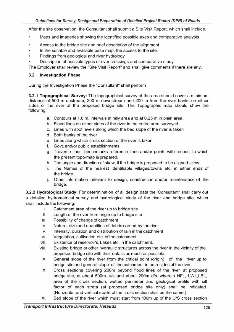
- 125 -
Guidelines for Survey, Design and Preparation of Detailed Project Report (DPR) of Roads
Transport Infrastructure Directorate, Hetauda
Guidelines for Survey Works Including Preparation of Detailed Project Report (DPR) of Roads
Transport Infrastructure Directorate, Hetauda
After the site observation, the Consultant shall submit a Site Visit Report, which shall include.
• Maps and imageries showing the identified possible axes and comparative analysis
• Access to the bridge site and brief description of the alignment
• In the suitable and available base map, the access to the site.
• Findings from geological and river hydrology
• Description of possible types of river crossings and comparative study
The Employer shall review the "Site Visit Report" and shall give comments if there are any.
3.2 Investigation Phase
During the Investigation Phase the "Consultant" shall perform
3.2.1 Topographical Survey: The topographical survey of the area should cover a minimum distance of 500 m upstream, 200 m downstream and 200 m from the river banks on either sides of the river at the proposed bridge site. The Topographic map should show the following:
a. Contours at 1.0 m. intervals in hilly area and at 0.25 m in plain area.
b. Flood lines on either sides of the river in the entire area surveyed.
c. Lines with spot levels along which the bed slope of the river is taken
d. Both banks of the river
e. Lines along which cross section of the river is taken
f. Govt. and/or public establishments
g. Traverse lines, benchmarks reference lines and/or points with respect to which
the present topo-map is prepared.
h. The angle and direction of skew, if the bridge is proposed to be aligned skew.
i. The Names of the nearest identifiable villages/towns etc. in either ends of
the bridge.
j. Other information relevant to design, construction and/or maintenance of the bridge.
3.2.2 Hydrological Study: For determination of all design data the "Consultant" shall carry out
a detailed hydrometrical survey and hydrological study of the river and bridge site, which
shall include the following:
I. Catchment area of the river up to bridge site
II. Length of the river from origin up to bridge site
III. Possibility of change of catchment
IV. Nature, size and quantities of debris carried by the river
V. Intensity, duration and distribution of rain in the catchment
VI. Vegetation, cultivation etc. of the catchment.
VII. Existence of reservoir's, Lakes etc. in the catchment.
VIII. Existing bridge or other hydraulic structures across the river in the vicinity of the
proposed bridge site with their details as much as possible.
IX. General slope of the river from the critical point (origin) of the river up to
bridge site and general slope of the catchment in both sides of the river.
X. Cross sections covering 200m beyond flood lines of the river at proposed
bridge site, at about 500m. u/s and about 200m d/s. wherein HFL, LWL,LBL,
area of the cross section, wetted perimeter and geological profile with silt
factor of each strata (at proposed bridge site only) shall be indicated.
(Horizontal and vertical scale of the cross section shall be the same.)
XI. Bed slope of the river which must start from 100m up of the U/S cross section
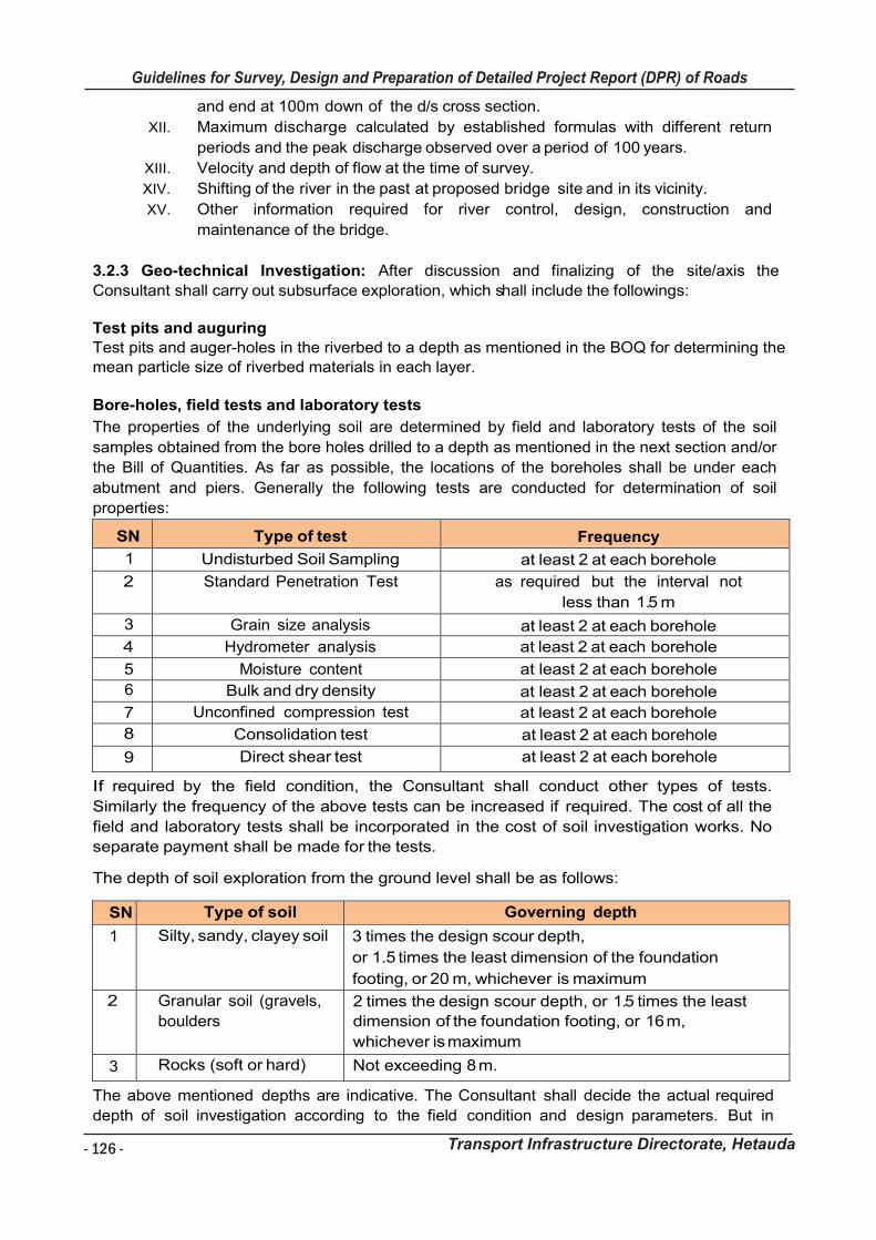
- 126 -
Guidelines for Survey, Design and Preparation of Detailed Project Report (DPR) of Roads
Transport Infrastructure Directorate, Hetauda
Guidelines for Survey Works Including Preparation of Detailed Project Report (DPR) of Roads
Transport Infrastructure Directorate, Hetauda
and end at 100m down of the d/s cross section.
XII. Maximum discharge calculated by established formulas with different return
periods and the peak discharge observed over a period of 100 years.
XIII. Velocity and depth of flow at the time of survey.
XIV. Shifting of the river in the past at proposed bridge site and in its vicinity.
XV. Other information required for river control, design, construction and
maintenance of the bridge.
3.2.3 Geo-technical Investigation: After discussion and finalizing of the site/axis the
Consultant shall carry out subsurface exploration, which shall include the followings:
Test pits and auguring
Test pits and auger-holes in the riverbed to a depth as mentioned in the BOQ for determining the
mean particle size of riverbed materials in each layer.
Bore-holes, field tests and laboratory tests
The properties of the underlying soil are determined by field and laboratory tests of the soil
samples obtained from the bore holes drilled to a depth as mentioned in the next section and/or
the Bill of Quantities. As far as possible, the locations of the boreholes shall be under each
abutment and piers. Generally the following tests are conducted for determination of soil
properties:
SN Type of test Frequency
1 Undisturbed Soil Sampling at least 2 at each borehole
2 Standard Penetration Test as required but the interval not
less than 1.5 m
3 Grain size analysis at least 2 at each borehole
4 Hydrometer analysis at least 2 at each borehole
5 Moisture content at least 2 at each borehole
6 Bulk and dry density at least 2 at each borehole
7 Unconfined compression test at least 2 at each borehole
8 Consolidation test at least 2 at each borehole
9 Direct shear test at least 2 at each borehole
If required by the field condition, the Consultant shall conduct other types of tests.
Similarly the frequency of the above tests can be increased if required. The cost of all the
field and laboratory tests shall be incorporated in the cost of soil investigation works. No
separate payment shall be made for the tests.
The depth of soil exploration from the ground level shall be as follows:
SN Type of soil Governing depth
1 Silty, sandy, clayey soil 3 times the design scour depth,
or 1.5 times the least dimension of the foundation
footing, or 20 m, whichever is maximum
2 Granular soil (gravels,
boulders
2 times the design scour depth, or 1.5 times the least
dimension of the foundation footing, or 16 m,
whichever is maximum
3 Rocks (soft or hard) Not exceeding 8 m.
The above mentioned depths are indicative. The Consultant shall decide the actual required
depth of soil investigation according to the field condition and design parameters. But in
Guidelines for Survey Works Including Preparation of Detailed Project Report (DPR) of Roads
Transport Infrastructure Directorate, Hetauda
any case the Consultant shall be paid only up to the depth mentioned in the Bill of
Quantities. If rock is found at the beginning or at mid-depth then the drilling works shall not
exceed the depth as mentioned in the table above. In such case the payment shall be
made only for the actual depth.
3.2.4 Reports of the Investigation Phase (Analysis of Data, Conclusion and Recommendation of Design Parameters):
The consultant perform concept design before proceeding with detail design, the
consultant shall inform the Client on;
o Geometry of the intended bridge
o Type of the bridge and its Structural arrangements
o Design Standards to be followed
o
For this, the consultant submit and Investigation and Concept Design Report based upon the above mentioned studies and investigation. Consultant shall make the best use of their technical know-how and professional skill to arrive at and recommend the most cost effective design parameters regarding appropriate river crossing. The consultant shall also in the Report discuss in detail at least three different options and shall recommend the most appropriate option for the proposed river crossing.
Design Phase
During the Design Phase the "Consultant" shall perform the following tasks.
Detailed design and quantity/cost estimates: Based on the collected and presented information in the "Preliminary Design Report" mentioned above the Consultant shall design the bridge following the approved standard codes of practice, norms and guidelines.
With the design, the consultant shall process Erection method and Risk analysis during flood, if there is any.
The Consultant shall produce detailed quantity estimate of the bridge and its accessories. The Consultant shall collect information on sources of materials and their lead distances and prepare rate schedules and cost estimates based on the standard norms and prevailing district rates.
Depending upon the site condition and other factors the Consultant can use the Standard Design of the part(s) of the bridge, which shall be made available by the Employer. This matter will be discussed and finalized during the presentation of the Preliminary Design or at a later stage convenient to both parties. If such Standard Design is used the Consultant shall
adjust the design of other parts of the bridge to incorporate the parameters of the Standard Design. If it is decided to use any Standard Design, the Payments shall be adjusted according to the Conditions of Contract and/or as mentioned in the Price Schedule.
Draft Report (2 Copies): The Consultant shall submit a Draft Design Report and the report
shall in all respect be complete, containing all the required components of the design. The Report shall be in the format as decided and required by the Client.
Final Report (5 copies). After receiving the comments in Draft Design the Consultant
shall consider the comments/suggestions and make corrections or amendments if required
and submit the Final Report. It does not, however, relieve the Consultant of their responsibility over the technical content of the design. The final report shall be submitted in electronic version too.
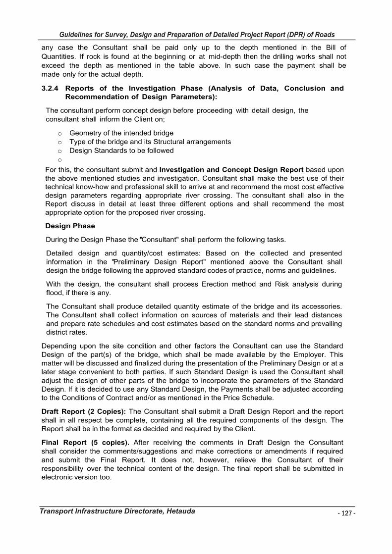
- 127 -
Guidelines for Survey, Design and Preparation of Detailed Project Report (DPR) of Roads
Transport Infrastructure Directorate, Hetauda
Guidelines for Survey Works Including Preparation of Detailed Project Report (DPR) of Roads
Transport Infrastructure Directorate, Hetauda
any case the Consultant shall be paid only up to the depth mentioned in the Bill of
Quantities. If rock is found at the beginning or at mid-depth then the drilling works shall not
exceed the depth as mentioned in the table above. In such case the payment shall be
made only for the actual depth.
3.2.4 Reports of the Investigation Phase (Analysis of Data, Conclusion and Recommendation of Design Parameters):
The consultant perform concept design before proceeding with detail design, the
consultant shall inform the Client on;
o Geometry of the intended bridge
o Type of the bridge and its Structural arrangements
o Design Standards to be followed
o
For this, the consultant submit and Investigation and Concept Design Report based upon the above mentioned studies and investigation. Consultant shall make the best use of their technical know-how and professional skill to arrive at and recommend the most cost effective design parameters regarding appropriate river crossing. The consultant shall also in the Report discuss in detail at least three different options and shall recommend the most appropriate option for the proposed river crossing.
Design Phase
During the Design Phase the "Consultant" shall perform the following tasks.
Detailed design and quantity/cost estimates: Based on the collected and presented information in the "Preliminary Design Report" mentioned above the Consultant shall design the bridge following the approved standard codes of practice, norms and guidelines.
With the design, the consultant shall process Erection method and Risk analysis during flood, if there is any.
The Consultant shall produce detailed quantity estimate of the bridge and its accessories. The Consultant shall collect information on sources of materials and their lead distances and prepare rate schedules and cost estimates based on the standard norms and prevailing district rates.
Depending upon the site condition and other factors the Consultant can use the Standard Design of the part(s) of the bridge, which shall be made available by the Employer. This matter will be discussed and finalized during the presentation of the Preliminary Design or at a later stage convenient to both parties. If such Standard Design is used the Consultant shall
adjust the design of other parts of the bridge to incorporate the parameters of the Standard Design. If it is decided to use any Standard Design, the Payments shall be adjusted according to the Conditions of Contract and/or as mentioned in the Price Schedule.
Draft Report (2 Copies): The Consultant shall submit a Draft Design Report and the report
shall in all respect be complete, containing all the required components of the design. The Report shall be in the format as decided and required by the Client.
Final Report (5 copies). After receiving the comments in Draft Design the Consultant
shall consider the comments/suggestions and make corrections or amendments if required
and submit the Final Report. It does not, however, relieve the Consultant of their responsibility over the technical content of the design. The final report shall be submitted in electronic version too.
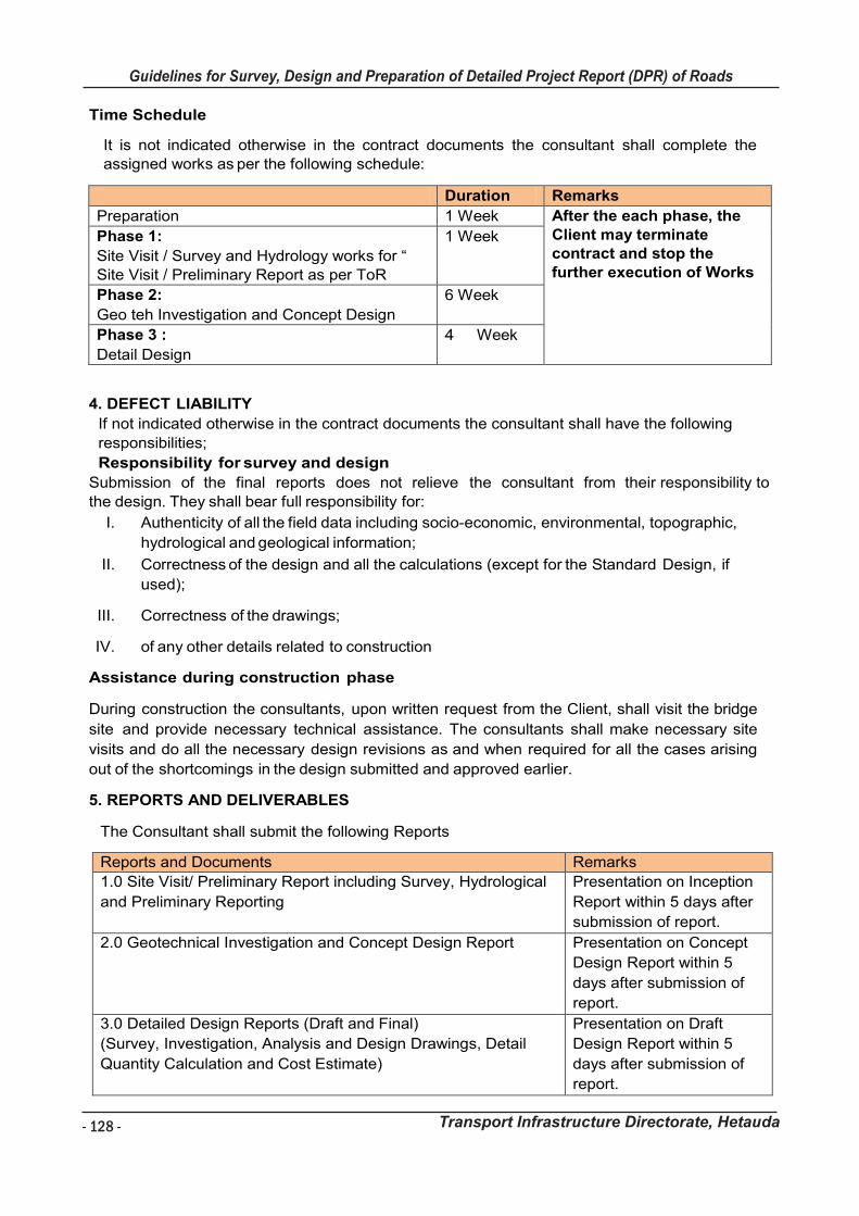
- 128 -
Guidelines for Survey, Design and Preparation of Detailed Project Report (DPR) of Roads
Transport Infrastructure Directorate, Hetauda
Guidelines for Survey Works Including Preparation of Detailed Project Report (DPR) of Roads
Transport Infrastructure Directorate, Hetauda
Time Schedule
It is not indicated otherwise in the contract documents the consultant shall complete the assigned works as per the following schedule:
Duration Remarks
Preparation 1 Week After the each phase, the Client may terminate contract and stop the further execution of Works
Phase 1:
Site Visit / Survey and Hydrology works for “ Site Visit / Preliminary Report as per ToR
1 Week
Phase 2:
Geo teh Investigation and Concept Design
6 Week
Phase 3 :
Detail Design
4 Week
4. DEFECT LIABILITY
If not indicated otherwise in the contract documents the consultant shall have the following
responsibilities;
Responsibility for survey and design
Submission of the final reports does not relieve the consultant from their responsibility to
the design. They shall bear full responsibility for:
I. Authenticity of all the field data including socio-economic, environmental, topographic,
hydrological and geological information;
II. Correctness of the design and all the calculations (except for the Standard Design, if
used);
III. Correctness of the drawings;
IV. of any other details related to construction
Assistance during construction phase
During construction the consultants, upon written request from the Client, shall visit the bridge
site and provide necessary technical assistance. The consultants shall make necessary site
visits and do all the necessary design revisions as and when required for all the cases arising
out of the shortcomings in the design submitted and approved earlier.
5. REPORTS AND DELIVERABLES
The Consultant shall submit the following Reports
Reports and Documents Remarks
1.0 Site Visit/ Preliminary Report including Survey, Hydrological
and Preliminary Reporting
Presentation on Inception
Report within 5 days after
submission of report.
2.0 Geotechnical Investigation and Concept Design Report Presentation on Concept
Design Report within 5
days after submission of
report.
3.0 Detailed Design Reports (Draft and Final)
(Survey, Investigation, Analysis and Design Drawings, Detail
Quantity Calculation and Cost Estimate)
Presentation on Draft
Design Report within 5
days after submission of
report.
Guidelines for Survey Works Including Preparation of Detailed Project Report (DPR) of Roads
Transport Infrastructure Directorate, Hetauda
4.0 As the part of the Final Report the consultant provide
o The electronic copy of the workable input files, if any
software has been used for the design
o The electronic copy of editable calculation sheets that have
been used during the design calculations.
All the reports are considered to be owned by Client.
All the Drawings and Reports shall be signed by the respective expert/engineers and checker
with clear names and contact indicating that it has been internally checked and approved prior
submission to client.
6. CONSULTANT' S TEAM
The Consultant shall engage a team of experts as mentioned below for the tasks as per this Terms of Reference
Minimum Qualification Requirement
Team Leader / Bridge Engineer Master degree with 10 years of general experience and 5 years of experience in bridge engineering
Geo-tech Engineer Master degree with 10 years of general experience and 5 years of experience in bridge engineering
Hydrologist Bachelor degree in any civil engineering field with 5 years of general experience and 2 years of experience in bridge engineering
Besides, the Consultant shall deploy all the required human resources and support staffs for
the completion of all the tasks as per this Terms of Reference.
7. TRANSFER OF KNOWLEDGE
As a part of "Transfer of Knowledge", the Consultant is required to perform the tasks
as indicated in the table below during the Design Phase;
Tasks Requirements
Presentation on submission of each report. All the cost
of this explanatory presentation shall be borne by the
consultant and is supposed to be included in the costs
stated in the Price Schedule.
Required
Perform the explanation of entire bridge design
process and calculations in the Client’s premises to
the designated persons of the Clients in a workshop.
All the cost of this explanatory workshop shall be
borne by the consultant and is supposed to be
included in the costs stated in the Price Schedule.
During the design of the bridge, the consultant take a
designated engineer of the Client to be with the design
of the Consultants as “on the job trainee (OJT)”. The
cost of this task to the consultant is supposed to be
included in the costs stated in the Price Schedule.
Required

- 129 -
Guidelines for Survey, Design and Preparation of Detailed Project Report (DPR) of Roads
Transport Infrastructure Directorate, Hetauda
Guidelines for Survey Works Including Preparation of Detailed Project Report (DPR) of Roads
Transport Infrastructure Directorate, Hetauda
4.0 As the part of the Final Report the consultant provide
o The electronic copy of the workable input files, if any
software has been used for the design
o The electronic copy of editable calculation sheets that have
been used during the design calculations.
All the reports are considered to be owned by Client.
All the Drawings and Reports shall be signed by the respective expert/engineers and checker
with clear names and contact indicating that it has been internally checked and approved prior
submission to client.
6. CONSULTANT' S TEAM
The Consultant shall engage a team of experts as mentioned below for the tasks as per this Terms of Reference
Minimum Qualification Requirement
Team Leader / Bridge Engineer Master degree with 10 years of general experience and 5 years of experience in bridge engineering
Geo-tech Engineer Master degree with 10 years of general experience and 5 years of experience in bridge engineering
Hydrologist Bachelor degree in any civil engineering field with 5 years of general experience and 2 years of experience in bridge engineering
Besides, the Consultant shall deploy all the required human resources and support staffs for
the completion of all the tasks as per this Terms of Reference.
7. TRANSFER OF KNOWLEDGE
As a part of "Transfer of Knowledge", the Consultant is required to perform the tasks
as indicated in the table below during the Design Phase;
Tasks Requirements
Presentation on submission of each report. All the cost
of this explanatory presentation shall be borne by the
consultant and is supposed to be included in the costs
stated in the Price Schedule.
Required
Perform the explanation of entire bridge design
process and calculations in the Client’s premises to
the designated persons of the Clients in a workshop.
All the cost of this explanatory workshop shall be
borne by the consultant and is supposed to be
included in the costs stated in the Price Schedule.
During the design of the bridge, the consultant take a
designated engineer of the Client to be with the design
of the Consultants as “on the job trainee (OJT)”. The
cost of this task to the consultant is supposed to be
included in the costs stated in the Price Schedule.
Required