Embed Size (px)
Citation preview
AD-A243 265
TECHCAL REPORT BRL-TR-3300
_ __ _ I Bi ... D T IC
IhL DECi I 1991
GUN TUBE HEATING
PAUL J. CONROY
DECEMBER 1991
APPROV rFOR PBuC R ,LEASE; D mUTION IS UNLahIunD.
0.Ma U.S. ARMY LABORATORY COMMAND
BALLISTIC RESEARCH LABORATORYABERDEEN PROVING GROUND, MARYLAND
i2 29-05-7-
NOTICES
Destroy this report when it is no longer needed. DO NOT return it to the originator.
Additional copies of this report may be obtained from the National Technical Information Service,U.S. Department of Commerce, 5285 Port Royal Road, Springfield, VA 22161.
The findings of this report are not to be construed as an official Department of the Army position,unless so designated by other authorized documents.
The use of trade names or manufacturers' names in this report does not constitute indorsementof any -commercial product.
-UNCLASSIFIED-_ _ _ _ _ _ _
REPORT DOCUMENT PAGE ~ai- ~3s . 19~9U 1I~mm1 11991W~Wq 1..~ ip.. a* f 6.6.0 ;1wm- =8118 -- fte ON" dM . IN OR .-
gewloa ~w~ Z a u 0 .a .. i*W d.dw8g1..dii .14u,*n .0 96.1 WM3EUbd. 9.9.a ay.E w 0 dseft"M of bdm-a. bohift ftewasow. aftut g, Ed. u.IYj0m
8e-6w" 31.69.. Dbwain" if bfialemmi @6.10. a" awleft, 1216 J~e.
DOW$. d9.wm. 0"4 120$ AUrg0e..-VA 222L4OU. ow ble On 014 0. Umosagma, ad %.ft. ape.Afb.at1dO04S. wlgs.D26
1. AGENCY USE ONLY aL"aV* hienki 2.- REMYR DATE 3.* REPORTTP N AE OEE
I December 199j Final, Feb 90 - Dec 90* 4. TILE AN SUTTS . FUNDING NURBERS
* ~~~Gun Tube HeatingPR L610A4
S.AUTHOR(S)
Paul J. Conroy
7. PERFORMING ORGANIZATION NAME(S) AND A-DDRFESSIES) 8. PERFORMING ORGANIZATIONREPORT NUMBER
S.-SPONSORINGIMONITORING AGMNCY NAMES(S) AND ADORESSIES) I 0.SPONSRING/MONITORt4AGENCY REPORT NUMBER
USA Ballistic Research Labo~ratoryATTN: SLCBR-DD-T BLT-3Aberdeen Proving Ground. MD 21005-5066
11. SUPPLEMENTARY NOTES
12a. DISTRIBUTION/iVAILABILITY STATEMENT 1 2b. DISTRIBUTiON CODE
Approved for Public Release - Distribution is UnlimitedJ
13. ABSTRACT Afazmwm 200 woods)A one-dimensional gun tube heating model has been coupled to an interior ballistic code. The ballistic
code models the two-phase interior ballistic cycle and provides intensive and extensive properties throughout thecycle. At the inner wall of the gun tube, a turbulent boundary layer correlation is used to compute the heatflux to the wall. This correlation incorporates the compressibility of the flow in calculating the Reynoldsnumber and skin friction coefficient. Within the tube wall, the one-dimensional radial heat conduction equationis solved.
The model is used to investigate gun tube thermal profiles over multiple firings with variable firing ratesfor two different weapons. Results are used to describe the transient heating of the gun tube over a longperiod of continuous firin g. Potential firing scenarios are presented and discussed. Numerical results arecompared to experimental work performed in the past. An extensive reference list is also includedl.
14. SBJECTTERMS15; NUMBE-OF PAGES
interior ballistics, barrel heating, heat transfer, heat counduction, thermal maaemn 321.PIECODE-
17 ECV lASKAM 1. ISCUNTY CIASSMAATIO#4 11. SEUT I CATION 20. UMIATMO OP -A&STRCT -
OF REW OF TMI PAOE OF *3mwPA
UNCLASSIFIED UNCLASSIFIED UNCLASSIFIED SARNSN 754".1 -2M05500 w d -29 f184
ptemibal by ANStWm 231UNCLASSIFIED 233.102

INTENTIONALLY LEFT B-LA•NK.
-__
=
TABLE.OF CONTENTS
LIST OF FIGURES ........................................... v-
ACKNOWLEDGMENTS ........................................ vii
1. INTRODUCTION ............................................. 1
2. ANALYTICAL DESCRIPTION .................................... 2
3. NUMERICAL CALCULATIONS ................................... 7
4. DISCUSSION ............................................... 7
5. CONCLUSIONS .............................................. 13
6. CODE IMPROVEMENTS UNDER IMPLEMENTATIONOR CONSIDERATION ...................................... 13
7. REFERENCES .............................................. 15
LIST OF SYMBOLS ........... .............................. 19
LIST OF ABBREVIATIONS ...................................... 21
DISTRIBUTION LIST .......................................... 23
Acoossio• ForNTIS GRA&I
DIMC T"
SDistribatlon/_ - ID-i3,ii1 a,,/or
Dia

INTENTIONALLY LEFT BLANK.
iv
LIST OF FIGURES
Figur~e Fage
1. Heat Transfer Code Flow Chart .................................. 6
2. Numerical Gun Tube Tempetature Calculation Results at Both the Innerand Outer Walls for the M203 Charge in a 155-mm Howitzer atthe Origin of Rifling for S Rounds Per Minute for 3 MinutesFollowed by 3 Rounds Per Minute Continuous ..................... 8
3. Experimental vs. Numerical Results for the Outer Gun TubeTemperature at the Origin of Rifling for the M203 Chargein a 155-mm Howitzer, Given the Firing Rate in Figure 2 .............. 8
4. Numerical Gun Tube Temperature Calculation Results at Both theInner and Outer Walls for the M203 Charge in a 155-mm Howitzerat the Origin of Rifling for 6 Rounds Per Minute for 5 MinutesFollowed by 3 Rounds Per Minute Continuous ..................... 9
5. Numerical Gun 1 ube Temperature Calculation Results at Both the Innerand Outer Wails for the M203 Charge in a 155-mm Howitzer at theOrigin of Rifling for 12 Rounds Per Minute for 5 MinutesFollowed by 3 Rounds Per Minute Continuous ..................... 9
6. A Comparison of Wall Temperature Profiles for the 12 Rounds PerMinute vs. the 6 Rounds Per Minute Scenarios After 30 Roundsand 6 Rounds Per Minute After 18 Rounds ....................... 10
7. Experimental Lccation of the Thermocouples for the 27-mm CAW Study ..... 12
8. Typ:cal Experimental Thermocouple Traces for the 27-mm CAW Study0.000254 m (0.01 in.) From the Inner Wall ........................ 12
9. Numerical Results for the 27-mm CAW Study at the Stop Shoulder0.000254 m (0.01 in.) From the inner Wall ........................ 13
v

INTENTIONALLY I EFT BLANK.
vi

ACKNOWLEDGMENTS
I wish to thank Dr. George Keller and Mr. Albert Horst for providing me the atmosphere,
tools, and time to do this work. Also, I would like to express my appreciation to
Satish Chandra of Veritay Corporation for many discussions on the heat conduction code and
Hugh McEiroy and his group at Olin Corporation for the deterred ball propellant chemical data.
vii

INTENTVONALLY LEFT BLANK.
viii
1. INTRODUCTION
The development of the Advanced Field Artillery System (AFAS), with its high rate-of-fire
requirement, has refocussed interest in the thermal management of gun tubes, which includes
consideration of cook-off of propellants and/or projectiles, tank gun accuracy, barrel wear and
erosion, and thermal signature. In the past, investigators have measured gun tube thermal
profiles for various weapons and they have employed heat conduction codes to model the gun
tube heating (see references). The lack of appropriate boundary conditions at the inner wall
surface compelled researchers to use ingenious approximation techniques (Rapp 1990) and
curve fitting to produce a history of tube heating during the interior ballistic cycle. One method
to produce the inner wall boundary condition was to use thermocouple measurements to
compute the heat input to the gun tube along its length. These measurements provided an
experimental axial heat input profile which then was used to model other similar systems.
This was accomplished by modifying the input profile using a ratio based on the total energy
cf the charge. This type of model neglects the mechanisms which lead to the development of
the thermal profile and, thus, does not allow the model to make predictions for a weapons
system significantly different from that used for the model calibration.
Barrel heating is due to forced convection of hot combustion gases, the projectile's sliding
friction, and obturator galling. In addition, there may be a significant radiative contribution to
the heating in the region of the breech (Leech 1972). Plastic obturators have reduced the
galling and sliding friction component considerably. A one-dimensional interior bahiistic (IB)
code can supply the information which is necessary for computing the interior boundary
condition at the wall, given a proper convective coefficient, which must include the effects of
pressure, gas velocity, and compressibility of the combustion products both spatially and
temporally.
Recently, Chandra (1990) and Chandra and Fisher (1989) have applied an IB code
(Gough 1980) to barrel heating. This work utilized the results from lB Lodes to provide an
appropriate inner wall boundary condition to the heat transfer/conduction routine.
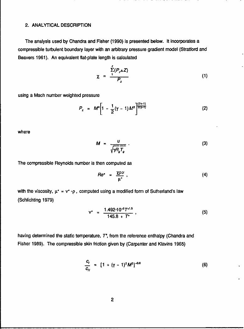
2. ANALYTICAL DESCRIPTION
The analysis used by Chandra and Fisher (1990) is presented below. It incorporates a
compressible turbulent boundary layer with an arbitrary oressure gradient model (Stratford and
Beavers 1961). An equivalent flat-plate length is calculated
z,(Pz'AZ)
x 1 , (1)Pz
using a Mach number weighted pressure
Pz = M4 1),2 (2)
where
M= U (3)
The compressible Reynolds number is then computed as
Re*= , ,__ (4)11.L
with the viscosity, p" = v .p, computed using a modified form of Sutherland's law
(Schlichting 1979)
V= 1.492.1 0-ST*15 (5)145.8 + T°
having determined the static temperature, T*, from the reference enthalpy (Chandra and
Fisher 1989). The compressible skin friction given by (Carpenter and Klavins 1965)
ct = [1 + (y - 1)2M2]-0'6 (6)c,'
2
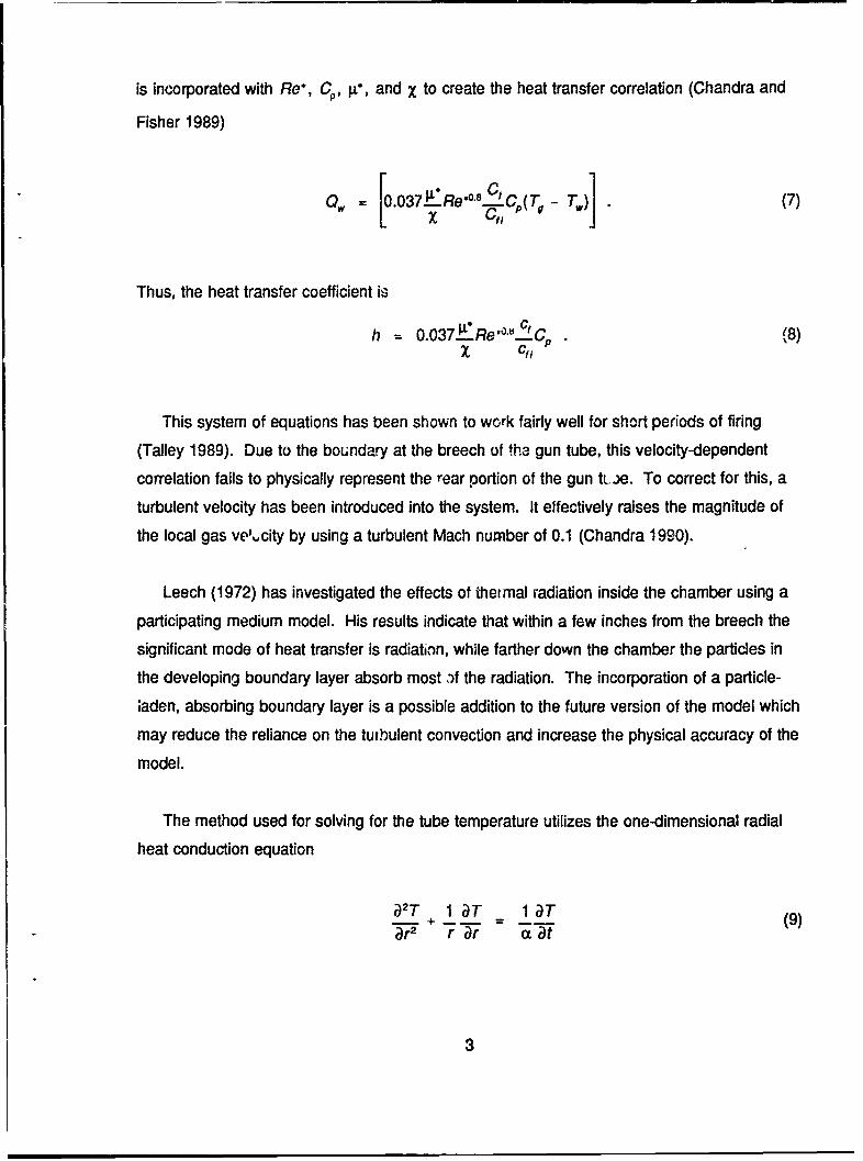
is incorporated with Re*, C,, g, and X to create the heat transfer correlation (Chandra and
Fisher 1989)
0. [.037.E:Re*°8 Cp(Tg - T.) (7)
Thus, the heat transfer coefficient is
h 0.037iLRe'°""fCp (8)
This system of equations has been shown to work fairly well for short periods of firing
(Talley 1989). Due to the boundary at the breech of tha gun tube, this velocity-dependent
correlation fails to physically represent the rear portion of the gun tu..,e. To correct for this, a
turbulent velocity has been introduced into the system. It effectively raises the magnitude of
the local gas ve',,city by using a turbulent Mach number of 0.1 (Chandra 1990).
Leech (1972) has investigated the effects of thermal radiation inside the chamber using a
participating medium model. His results indicate that within a few inches from the breech the
significant mode of heat transfer is radiation, while farther down the chamber the particles in
the developing boundary layer absorb most ,f the radiation. The incorporation of a particle-
;aden, absorbing boundary layer is a possible addition to the future version of the model which
may reduce the reliance on the turbulent convection and increase the physical accuracy of the
model.
The method used for solving for the tube temperature utilizes the one-dimensional radial
heat conduction equation
oJ2T+ 1_T _lT (9)r_2 r ar ac a~t
with theo internal boundary condition given as a specified heat flux
-k T = h(Tg - T,) (10)
and an insulated external boundary. The physical properties of the gun steel are treated as
constants throughout the calculation; however, the properties presented by the Mechanical
Properties Data Center (Belfour Stulen Inc. 1973) show a reduction in the conductivity and a
sharp spike at 1,400 K in the specific heat with an increase in temperature.
The equations are explicitly computed using central differences and the grid has been
generated using a geometric factor to account for the radial geometry and the fine grid
necessary at the inner wall. An allowance has been made for various materials, such as
chrome, to be included in the tube.
The model used in this paper incorporates the one-dimensional NOVA (Gough 1980)
IB code to provide the necessary state variables for the calculation of the convective heat
transfer coefficient described previously. Typically, the duration of an IB cycle is on the order
of 50 ms or less; however, for heat transfer studies, the IB cycle is assumed to be from the
time of the first round until the barrel reaches ambient temperature or until the next round is
fired. The requirement on the IB code to produce the necessary state variables after shot exit
for up to six orders of magnitude in time greater than a typical IB calculation necessitates the
use of a open muzzle boundary condition after shot exit. Gough (1980) uses an isentropic
(Eq. 11)
2= go (yRL)[- 1 ; P',] + 2bP (11)
A0M 0+b
P.
4
or choked (Eq. 12)
= A.o PlYg 2 1 [1. - 0.224y + O.104y 2] (12)
mass flux calculation for either subsonic or supersonic exit flow, respectively, thus allowing the
gas flow out the gun muzzle to continue to empty the gun tube. This allows the IB code to
compute the thermodynamic expansion cooling, rather than using a linear interpolation to
ambient conditions. This calculation can be maintained for about 80 ms, by which time the
breech pressure has reached ambient and the NOVA code stops. The other state variables
are then brought to ambient through either a conservative linear interpolation or a special
exponential function which reduces the state variables to ambient after a short amount of time
(about 1-2 s) with respect to the cycle time. The exponential decay function resulted in the
prediction of approximately 3% lower inner wall temperatures after 30 rounds at 12 rounds per
minute are fired in the 155-mm M199 cannon, using an M203 charge. This implies that a
conservative approach will trade a small increase in wall temperature for confidence that the
experimental temperature will not exceed the computed values.
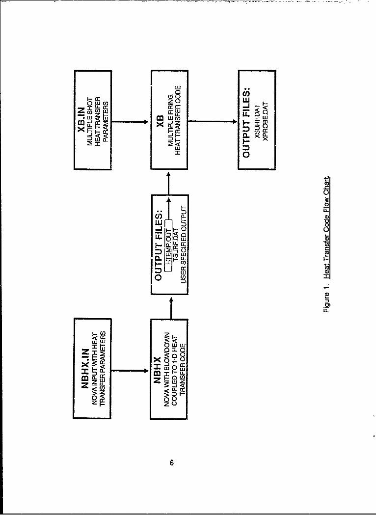
Figure 1 presents the flow chart of a conduction calculation using the Chandra and Fisher
model. The state variables are stored temporally and spatially in the HTEMP.OUT file, thus
creating an IB "signature" for a specific charge. This signature can then be utilized to study
various firing scenarios assuming that the feedback to the IB calculation is small. The heat
transfer and conduction code XB is used to make various scenario studies with the signature
file as an input along with the desired scenario defined in the input deck XB.IN.
The output of this IB code for one round is then used in a separate uncoupled interpolation
and heat transfer/conduction routine. Given the history of one round, this stand-alone routine
allows the user to define various firing scenarios assuming no feedback to the next charte by
the rising tube temperature.
5
0WUa:2)
0 w U) C-) uM LL C cc _
Z U) - <0
U) LLU. a,
I-
a- 0
0<0)
C0)
0 0)
zl
cc6
3. NUMERICAL CALCULATIONS
There are two weapons systems for which experimental heating data exist; we chose to
perform this study by modeling these two systems. One system involves the use of the M203
charge in a 155-mr.i nowitzer; the other is a 27-mm casc!ess Olin round. The 1979 Thermal
Warning Devirc (TWD) study by Vottis and Hasenbein (1979) provides the 155-mm data. The
27--..,,, cnarge (Williams 1972) presents a rapid, uniform rate of fire.
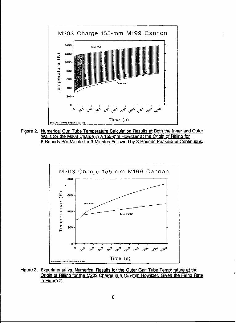
4. DISCUSSION
The M203 experimental data are presented in the TWD study in many forms with various
rates of fire over periods of time. The scenario of 6 rounds per minute for 3 min followed by
3 rounds per minute continuous has been modeled and presented in Figure 2. A comparison
of the experimental and numerical outer tube wail temperature history shown in Figure 3 has
been made at the origin of rifling. This comparison reveals the importance of an external heat
transfer coefficient if the calculation is to cover long periods of firing, for the temperatures
keep rising while the experimental data level off. The temperature rise rate for the numerical
calculation is about 1.8 times that of the experimental data. This causes the data presented
here to be incorrect quantitatively, but qualitatively useful. There is a significant lag in the
response of the outer tube wall from the first round for the numerical computations which
reflects the amount of time for the heat to diffuse to the outer wall.
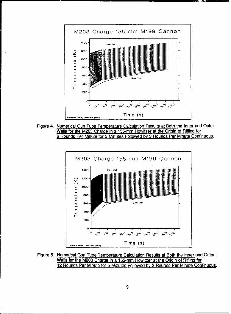
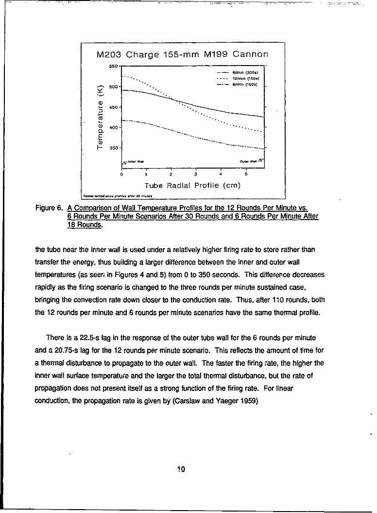
Two other scenarios performed on the M203 charge were 6 vs. 12 rounds per minute for
5 minutes and then 3 rounds minute thereafter for 100 rounds. The temperature was
recorded at the origin of rifling. The results are presented for the inner and outer wall surface
temperatures in Figures 4 and 5. The differences between 6 and 12 rounds per minute reveal
themselves in the radial thermal profile of the gun tube over a period of time. Figure 6 shows
the radial profile of the gun tube for three situations: 12 rounds per minute for 30 rounds and
6 rounds per minute for 15 and 30 rounds. What is seen between the two scenarios is that
the tube's constant diffusivity does not transport the heat into the barrel as rapidly when the
heat-flux rate at the inner wall is higher. This is true because a thermal barrier develops at
the inner wall which prevents as much heat transfer to occur per round as that of the lower
firing rate scenario. This shows that given a fixed number of rounds fired, the heat capacity of
7
M203 Charge 155-mm M199 Cannon1400-
1200 -nnt wMI I i1000
. 800-
¢0
I-
S600
ED 400-
200
0 0 . i i IS 11100 bo0 @0 so
Time (s)6,nostmit {3rain) 3t00imlrin (ctoni)
Figure 2. Numerical Gun Tube Temperature Calculation Results at Both the Inner and OuterWalls for the M203 Charge in a 155-mm Howitzer at the Ori.in of Rifling for6 Rounds Per Minute for 3 Minutes Followed by 3 Rounds Per "Ainuie Continuous.
M203 Charge 155-mm M199 Cannon800
600-
(• 400 -
I0
o ) 200O 0@ 0 0-~0 0@
,.Q 1.01, zoI 101 Isq 10 , 0 , S1 9,0
3 (can[ Time (s)
Figure 3. Experimental vs. Numerical Results for the Outer Gun Tube Tempr ature at theOrigin of Rifling for the M203 Charge in a 155-mm Howitzer, Given the Firing Ratein Figure 2.
8
M203 Charge 155-mm M199 Cannon
2 1200 - ~ * ~
0)1000-
400-CIO
2 00-
010 s 00 b.0 5 40 "Il 0 0 110 1-13, 11, "!,, eo~
Time (s)
Figure 4. Numerical Gun Tube Temperature Calculation Results at Both the Inrner and OuterWalls for the M203 Char-ge in a 155-mm Howitzer at the Origin of Rifling for6 Rounds Per Minute for 5 Minutes Followed by 3 Rounds Per Mknute Continuous.
M203 Charge 155-mm M199 Cannon
1400 1o.- Wotiii II
. 1200
QD 1000 '
... 800
600
0-
0 S! .3 @0 0 "Is 400o .Go "00 "bo 'Poo
(50(0)~O.I0L.(tol)Time (s)
Figure 5. Numerical Gun Tube Temperature Calculation Results at Both the Inner and OuterWalls for the M203 Charge in a 155-mm Howitzer at the Origin of Rifling for12 Rounds Per Minute for 5 Minutes Followed by 3 Rounds Per Minute Continuous.
9
M203 Charge 155-mm M199 Cannon550
- 61min (300s)" " •-. . '-•--... 12/rain (150s)
t 500- .6/rain (1503,
S450-
() 400 "" ..- "- - -.
400
350 1 k
I=n1. W.i1 OUter W.1
0 1 2 3 4 5
Tube Radial Profile (cm)A801.1l t.-POWI.tl PIoW-W. Oifte. 30 r,.ud.
Figure 6. A Comparison of Wall Temperature Profiles for the 12 Rounds Per Minute vs.6 Rounds Per Minute Scenarios After 30 Rounds and 6 Rounds Per Minute After18 Rounds.
the tube near the inner wall is used under a relatively higher firing rate to store rather thantransfer the energy, thus building a larger difference between the inner and outer wall
temperatures (as seen in Figures 4 and 5) from 0 to 350 seconds. This difference decreases
rapidly as the firing scenario is changed to the three rounds per minute sustained case,
bringing the convection rate down closer to the conduction rate. Thus, after 110 rounds, both
the 12 rounds per minute and 6 rounds per minute scenarios have the same thermal profile.
There is a 22.5-s lag in the response of the outer tube wall for the 6 rounds per minute
and a 20.75-s lag for the 12 rounds per minute scenario. This reflects the amount of time for
a thermal disturbance to propagate to the outer wall. The faster the firing rate, the higher theinner wall surface temperature and the larger the total thermal disturbance, but the rate of
propagation does not present itself as a strong function of the firing rate. For linear
conduction, the propagation rate is given by (Carslaw and Yaeger 1959)
10
a =- I2 k (13)
with CP being the specific heat of the barrel. The propzgation rate is not so easily traceable
analytically for tadial systems with time-dependant bnundary conditions. However, from the
numerical experiment, it appears that a ratio difference of 10'", or about 1c, exists between the
linear propagation function and that of the higher numerical result.
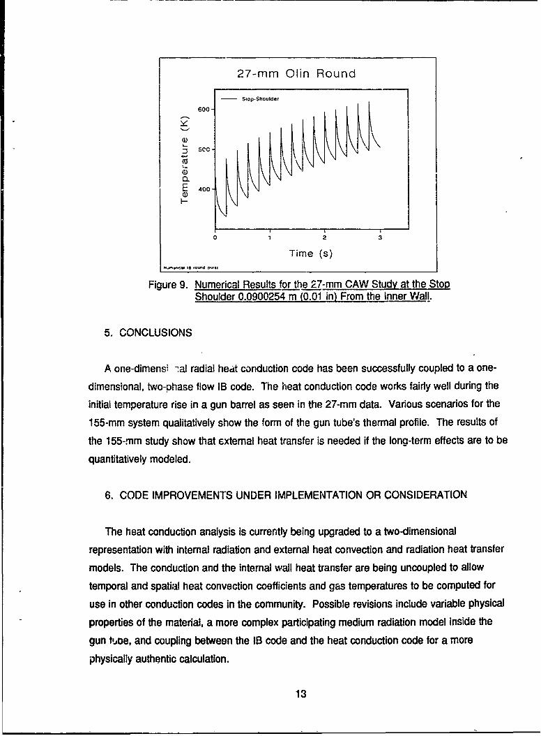
Figure 7 shows the experimental chamber and thermocouple placements for the 27-mm
Caseless Automatic Weapon (CAW). The thermocouples were designed and built by Comell
Aeronautical Laboratory and placed between 0.0254 cm and 0.0508 cm away frc n the inner
wall. Typical thermocouple traces are shown in Figure 8. What can be seen in Figure 8 is
the convective nature of the heat transfer in that the recorded temperature decreases from the
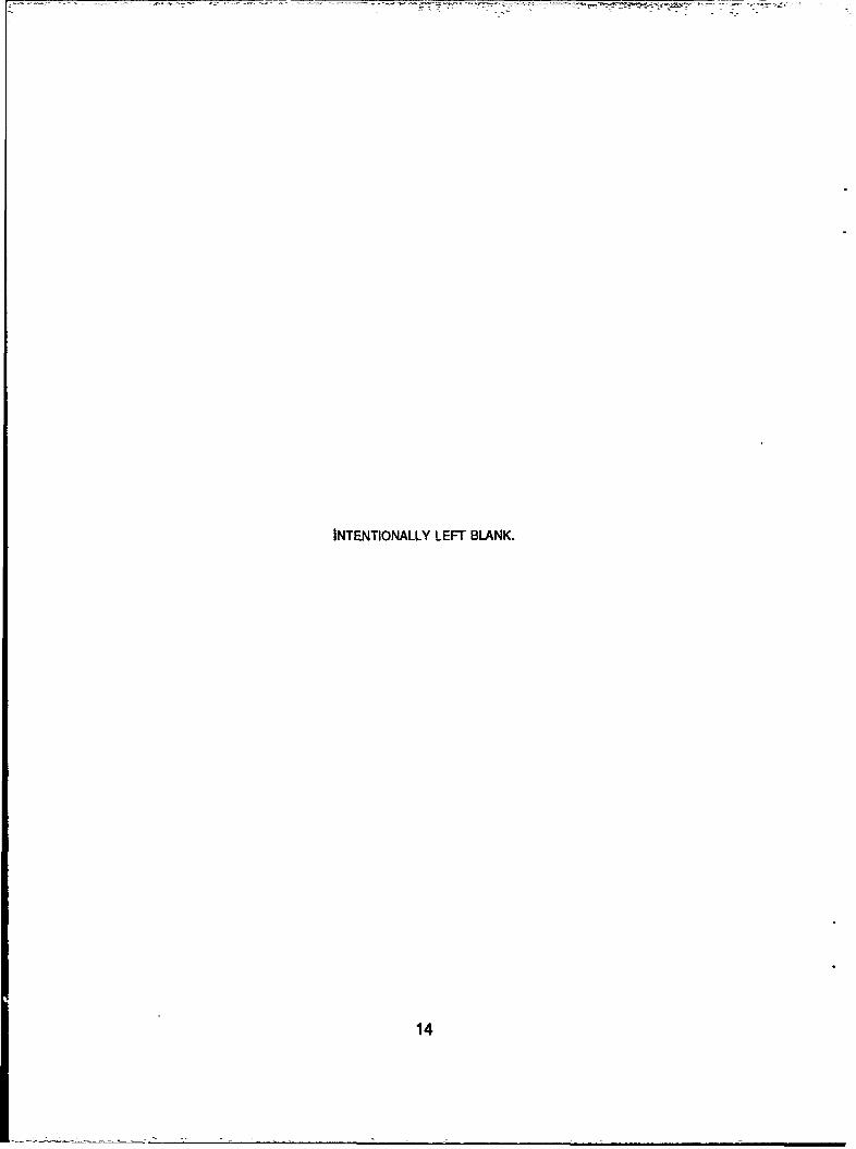
front of the chamber to the breech where the cross flow is small. The stop shoulder location
was used for demonstrative modeling, the results of which are presented in Figure 9. The
experimental and numerical peak temporatures match well after four rounds. The simulation
models the experiment well because the outer barmel wall does not respond during the 3-s
burst. There is a lag not numerically represented in the experimental data at the initiation of
the burst. This could possibly be due to a small amount of ambient air surrounding the back
side of the thermocouple acting as a heat sink, thus lowering the thermocouple's reading until
the air became heated.
The rate dependency of the outer wa!l temperature shows the futility of using a TWD on
the outer wall without the gun's recent firing history. A TWD could be very effective without
any historical knowledge or tabularized data if it gave the inner tube wall temperature prior to
loading.
11
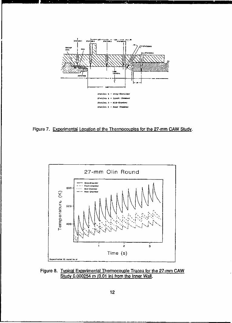
"STAION I STATION2 hTAT• i TATWN i
Sttiton ! - Stop-ShoSLder
Staltion 4 - Fronlt c2llaaber
Station 3 - 141d-chllbaabl
S~ltaton 2 - tarll chaa~b~r
Figure 7. Experimetal. Location of the Thermocouples for the 27-mm CAW Study.
27-mam Olin Round
600- ---. dhmo
-I 500-
• .I,... , ... , , , I -.. ;
121
400 Time (s)
Figure 8. Typical Experimental Thermocoup!e Traces for the 27-mm CAWStudy 0.000254 m (0.S01 in) from the rnner Wall.
12
27-mm Olin Round
0 - Slop-Shoulder
0 1 2 3
Time (s)NJ4fcllfCt 15 ©n ICIfl rMS
Figure 9. Numerical Results for the 27-mm CAW Study at the StopShoulder 0.0900254 m (0.01 in) From the Inner Wall.
5. CONCLUSIONS
A one-dimensi -al radial heat conduction code has been successfully coupled to a one-
dimensional, two-phase flow IB code. The heat conduction code works fairly well during the
initial temperature rise in a gun barrel as seen in the 27-mm data. Various scenarios for the
155-mm system qualitatively show the form of the gun tube's thermal profile. The results of
the 155-mm study show that extemal heat transfer is needed if the long-term effects are to be
quantitatively modeled.
6. CODE IMPROVEMENTS UNDER IMPLEMENTATION OR CONSIDERATION
The heat conduction analysis is currently being upgraded to a two-dimensional
representation with internal radiation and external heat convection and radiation heat transfer
models. The conduction and the internal wall heat transfer are being uncoupled to allow
temporal and spatial heat convection coefficients and gas temperatures to be computed for
use in other conduction codes in the community. Possible revisions include variable physical
properties of the material, a more complex participating medium radiation model inside the
gun toe, and coupling between the IB code and the heat conduction code for a more
physically authentic calculation.
13
INTENTIONALLY LEFT BLANK.
14
7. REFERENCES
Anderson, L. W., . "Numerical Solution of the Nonsteady Boundary LayerEquations With the Application to Convective Heat Transfer in Guns." Aerotherm FinalReport, Naval Ordinance Station, Indian Head, MD, 1972 (AD-894601).
Artus, B., and R. Hasenbein. "Thermal Study of the 120-mm M256 Cannon Tube."ARBCCB-TR-89029, Benet Weapons Laboratory, U.S. Army Armament Research,Development and Engineering Center, Watervliet, NY, October 1989.
Bannister, E. L., R. N. Jones, and D. W. Bagwell. "Heat Transfer, Barrel Temperatures, andThermal Strains in Guns." BRL Report No. 1192, U.S. Army Ballistic ResearchLaboratory, Aberdeen Proving Ground, MD, February 1963 (AD-404467).
Beffour Stulen Inc. Structural Alloys Handbook, Mechanical Properties Data Center, 1973.
Brosseau, T. L. "An Experimental Method for Accurately Determining the TemperatureDistribution and the Heat Transferred in Gun Barrels." BRL-TR-1740, U.S. Army BallisticResearch Laboratory, Aberdeen Proving Ground, MD, 1974 (AD-B0001712).
Brosseau, T. L., I. C. Stobie, J. R. Ward, and R. W. Greene. "120-mm Gun Heat InputMeasurements." ARBRL-TR-02413, U.S. Army Ballistic Research Laboratory, AberdeenProving Ground, MD, July 1982 (AD-Al 18378).
Bundy, M. L. "Thermal Distortion of the M1Al Muzzle Reference System Collimator (MRSC)."BRL-TR-3107, U.S. Army Ballistic Research Laboratory, Aberdeen Proving Ground, MD,June 1990.
Bundy, M. L., A. W. Horst, and F. W. Robbins. "Effect of In-Bore Heating of Projectile Fins."BRL-TR-3106, U.S. Army Ballistic Research Laboratory, Aberdeen Proving Ground, MD,June 1990.
Carpenter, J. E., and A. Klavins. "Heat Flux Calculations." Memorandum. CornellAeronautical Laboratory Hypersonic Tunnel Department, 16 June 1965.
Carslaw, H. S., and J. C. Yaeger. Conduction of Heat in Solids. Oxford University Press,Second Edition, 1959.
Chandra, S. "Reference Manual for Stand-Alone Version of NBHX's Barrel Radial HeatConduction Routines With Burst Fire and Restart Options." XBR-3.0-001, Veritay Corp.,East Amherst, NY, May 1990.
Chandra, S., and E. B. Fisher. "Simulation Of Barrel Heat Transfer." Final Report, ContractNo. DAAA15-88-D-0014, Delivery Order 0002, U.S. Army Laboratory Command,U.S. Army Ballistic Research Laboratory, Aberdeen Proving Ground, MD, June 1989.
15
Edwards, A. L. "Trump: A Computer Program for Transient and Steady State Distributions inMultidimensional Systems." UCRL-14754, Rev. 3, Lawrence Livermore NationalLaboratory, Livermore, CA, 1972.
Gibeling, H. J., and H. McDonald. "Development of a Two-Dimensional Implicit InteriorBallistics Code." Scientific Research Associates Inc., Glastonbury, CT, 20 November1979 (AD-A100276).
Gough, P. S. "The NOVA Code A Users Manual," Volume I, "Description and Use."IHCR-80-8, Naval Ordinance Center, Indian Head, MD, December 1980.
Hass, J. R. "Resistance Model and Suggested Improvements for Thermal Shrouds of TankGuns." ARCCB-TR-88035, U.S. Army Research and Development Command, August1988 (AD-B1i26969).
Heiser, R., and J. A. Schmitt. "Simulations of Special Intericr Ballistic Phenomena With andWithout Heat Transfer to the Gun Tube Wall." BRL-TR-2732, U.S. Army BallisticResearch Laboratory, Aberdeen Proving Ground, MD, May 1986 (AD-A169318).
Kingsbury, H. B., and A. V. Kalbag. "A Study of Thermal Shield Temperature Changes onGun Tube Curvature." BRL-CR-61 1, U.S. Army Ballistic Research Laboratory, AberdeenProving Ground, MD, June 1989 (AD-A209551).
Koszoru, A. A., and I. C. Stobie. "Comparison of 155-mm Gun Tube Heat Input WithSolventless and Solvent Propellant." BRL-MR-3833, U.S. Army Ballistic ResearchLaboratory, Aberdeen Proving Ground, MD, June 1990.
Kuo, K. K., K. C. Hsieh, and M. M. Athavale. "Modeling of Combustion Processes of StickPropellants via Combined Eulerian-Lagrangian Approach." Proceedings of the EighthInternational Symposium on Ballistics, October 1984.
Lawton, B. "Heat Transfer in Gun Sarrels." Mechanical Engineering Department RMCS,Swindon Wilts SN68LA, UK, 1988.
Lawton, B. "Measurement of Instantaneous Nusselt Number-Reynolds Number Relationshipsin Gun Barrels." Mechanical Engineering Department RMCS, Swindon Wilts SN68LA, UK,October 1990.
Leech, W. J. "An Analytical Study of Thermal Radiation Heat Transfer in Gun Tubes."SWERR TR-72-32, June 1972 (AD-746231).
Liedtke, L. L. "Heat Transfer Characteristics of a Rapid-Fire Liquid Propellant Gun."Naval Weapons Center, China Lake, CA, January 1976 (AD-A022083).
Minor, T. C., R. W. Deas, and F. R. Lynn. "Rational Design of Thermal Jackets for TankGuns." ARBRL-TR-02247, U.S. Army Ballistic Research Laboratory, Aberdeen ProvingGround, MD, August 1980 (AD-B051586L).
16
Morphy, C. C., and E. B. Fisher. "Gas Chemistry Effects on Gun Barrel Erosion: A ShockTube Gun Investigation." ARBRL-CR-00481, U.S. Army Ballistic Research Laboratory,Aberdeen Proving Ground, MD, July 1980 (AD-A116-192).
O'Hara, G. P. "Principles of Thermal Analysis of Failures in Machine Gun Barrels."Benet Weapons Laboratory d-aft report, Applied Mechanics, Watervliet, NY.
Olin Corp. "Feasibility Study Semitelescoped Caseless 27-mm Ammunition." Final Report,New Products Development Energy Systems Division, St. Marks, FL, April 1972(AD-903908).
Polk, J. F. "An Algorithm for Heat Transfer in Gun Barrels." ARO Report 80-1, Transactionsof the 25th Conference of Army Mathematicians, pp.125-145, U.S. Army ResearchOffice, Triangle Park, NC, 1980.
Rapp, J. A. "Gun Tube Temperature Prediction Model." BRL-MR-3844, U.S. BallisticResearch Laboratory, Aberdeen Proving Ground, MD, July 1990.
Schlichting, H. Boundary Layer Theory. New York, NY: McGraw-Hill Book Company,Seventh Edition, 1979.
Sill, M. H., Jr. "Theoretical and c.xperimental Analyses of a Cannon Launched GuidedProjectile (CLGP)." Report R-TR-74-049, U.S. Army Armament, Munitions and ChemicalCommand, Rock Island, IL, October 1974 (AD-B001002).
Sterbutzel, G. A., D. E. Adams, and F. A. Vassallo. "Evaluation of Heating and Erosion forExperimental 105-mm Ammunition." ARLCD-CR-80068, U.S. Army Research andDevelopment Command, August 1980 (AD-B056222).
Stiefel, L., and E. C. Gros-smann. "The Cook-Off Problem in Caseless Liquid PropellantGuns." Report R-1 686, Frankfort Arsenal, August 1963 (AD-345630)
Stobie, I. C., T. L. Brosseau, and R. P. Kaste. "Heat Transfer Measurements in 105-mm TankGun With M735 Rounds." ARBRL-TFI-02265, U.S. Army Ballistic Research Laboratory,Aberdeen Proving Ground, MD, September 1980.
Stratford, B. S., and G. S. Beavers. "The Calculation of the Compressible Turbulent BoundaryLayer in an Arbitrary Pressure Gradient - A Correlation of Certain Previous Methods."Aeronautical Research Council R&M No. 3207, 1961.
Sturek, W. B., H. A. Dwyer, and E. N. Ferry, Jr. "Prediction of In-Bore Heating of KEProjectile Fins." BRL-MR-3852, U.S. Army Ballistic Research Laboratory, AberdeenProving Ground, MD, August 1990.
Talley, Q. J. "Barrel Heating and Chrome Adhesion in the 120-mm M256 Gun Tube."Contractors Report DAAA21-85-C0389, U.S. Army Research and Development Command,1989.
17
U.S. Army Materiel Command. Interior Ballistics of Guns, AMCP 706-150, Alexandria,VA, February 1965.
Vassallo, F.A. "An Evaluation of Heat Transfer and Erosion in the 155-mm M185 Cannon."Calspan Technical Report No. VL-5337-D, 1 July 1976a.
Vassallo, F. A. "Development of Tube Instrumentation and Shock Tube Gun Techniques forInvestigation of Heat Transfer and Erosion in Large-Caliber Guns: 8-in Howitzer Studies."Calspan Report No. VL-5,3G7-D-2, December 1976b (AD-B031206).
Vassallo, F. A. "Mathematical Models and Computer Routines Used in Evaluation of CaselessAmmunition Heat Transfer." Calspan Reports No. GM-2948-Z-1 through 3, June 1971.
(AD-A034159).
Versteegen, P. L. ---------- "A Heat Transfer Study in Folded Ammunition Gun TubeChambers." ARBRL-CR-00342, U.S. Army Ballistic Research Laboratory, AberdeenProving Ground, MD, July 1977 (AD-A043280)
Versteegen, P. L., and F. D. Varcolik. "Heat Transfer in Gun Tubes." ARBRL-CR-00393,U.S. Army Ballistic Research Laboratory, Aberdeen Proving Ground, MD, March 1979(AD-A069649).
Vottis and Hasenbein. "Therma.! Warning Device (TWD) for the M198 155-mm Howitzer."DRDAR-LCB-DA, Benet Weapons Laboratory, Watervliet, NY, August 1979.
Williams, D. S. "27-mm Experimental Caseless Firing Fixture Test Program CAW-T2."Technical Report R-RR-N-x-18-73, U.S. Army Armament, Munitions and ChemicalCommand, Rock Island, IL, August 1972 (AD-909092).
Yalamanchili, V. S. "Unsteady Heat Transfer Analysis for Chosen Ammunition and Gun."U.S. Army Armament, Munitions and Chemical Command, Rock Island, IL, November1972 (AD-755111)
18
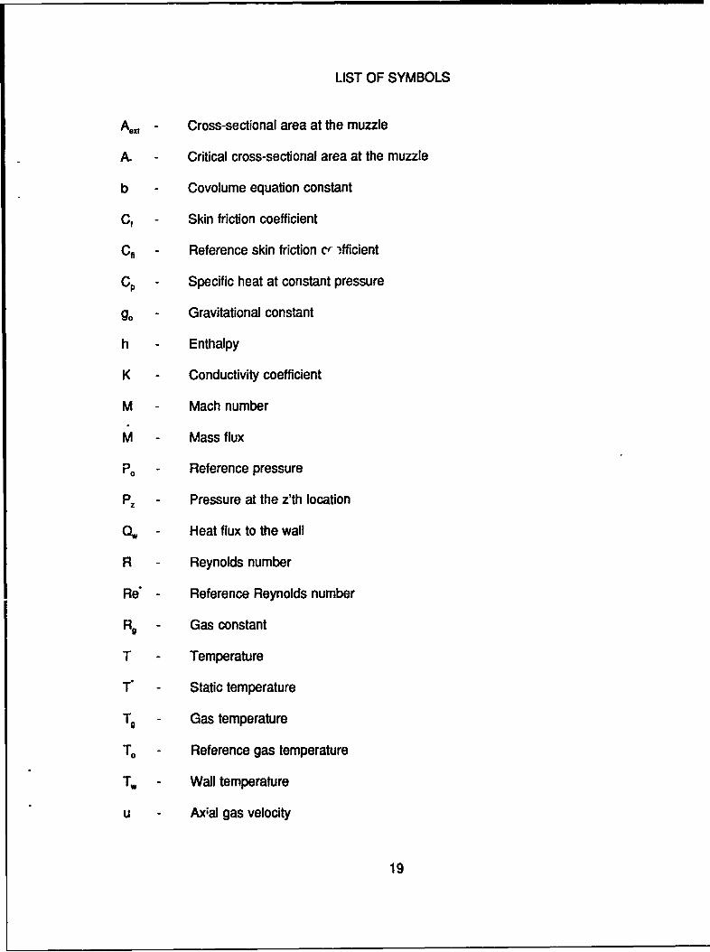
LIST OF SYMBOLS
A - Cross-sectional area at the muzzle
A. - Critical cross-sectional area at the muzzle
b - Covolume equation constant
Cf - Skin friction coefficient
Cfi - Reference skin friction cr ifficient
CP- Specific heat at constant pressure
0 - Gravitational constant
h - Enthalpy
K - Conductivity coefficient
M - Mach number
M - Mass flux
P, - Reference pressure
P - Pressure at the z'th location
0 -, Heat flux to the wall
R - Reynolds number
Re - Reference Reynolds number
R9 - Gas constant
T - Temperature
T - Static temperature
T - Gas temperature
T - Reference gas temperature
T, - Wall temperature
u - Axal gas velocity
19
y Covolume correction
z Axial position
a Thermal diffusivity
y Ratio of specific heats
p.I Reference viscosity
p Density
v Reference kinematic viscosity
X Equivalent flat plate length
) Frequency of heat input
20

LIST OF ABBREVIATIONS
AFAS - Advanced Field Artillery System
lB - Interior Ballistic
TWD - Thermal Warning Device
CAW - Caseless Automatic Weapon
21

INTENTIONALLY LEFT BLANK.
22
No. of No. ofCopies Organization C Oranization
2 Administrator I CommanderDefense Technical Info Center U.S. Army Missile CommandATTN: DTIC-DDA ATrN: AMSMI-RD-CS-R (DOC)Cameron Station Redstone Arsenal, AL 35898-5010Alexandria, VA 22304-6145 1 Commander
Commander U.S. Army Tank-Automotive CommandU.S. Army Materiel Command ATTN: ASQNC-TAC-DIT (TechnicalATTN: AMCAM Information Center)5001 Eisenhower Avenue Warren, MI 48397-5000Alexandria, VA 22333-0001 1 DirectorCommander U.S. Army TRADOC Analysis CommandU.S. Army Laboratory Command ATTN: ATRC-WSRATTN: AMSLC-DL White Sands Missile Range, NM 88002-55022800 Powder Mill RoadAdelphi, MD 20783-1145 1 Commandant
U.S. Army Field Artillery School2 Commander ATTN: ATSF-CSI
U.S. Army Armament Research, Ft. Sill, OK 73503-5000Development, and Engineering Center
ATTN: SMCAR-IMI-I (Cls. only)1 CommandantPicatinny Arsenal, NJ 07806-5000 U.S. Army Infantry School
ATTN: ATSH-CD (Security Mgr.)2 Commander Fort Benning, GA 31905-5660
U.S. Army Armament Research,Development, and Engineering Center (unto==. o14y)1 Commandant
ATTN: SMCAR-TDC U.S. Army Infantry SchoolPicatinny Arsenal, NJ 07806-5000 A'TN: ATSH-CD-CSO-OR
Fort Benning, GA 31905-5660DirectorBenet Weapons Laboratory 1 Air Force Armament LaboratoryU.S. Army Armament Research, ATTN: WL/MNOI
Development, and Engineering Center Eglin AFB, FL 32542-5000A'TN: SMCAR-CCB-TLWatervliet, NY 12189-4050 Aberdeen Provinq Grvund
(Unclas. only)1 Commander 2 Dir, USAMSAAU.S. Army Armament, Munitions ATrN: AMXSY-D
and Chemical Command AMXSY-MP, H. CohenATTN: AA4SMC-IMF-LRock Island, IL 61299-5000 1 Cdr, USATECOM
ATrN: AMSTE-TCDirectorU.S. Army Aviation Research 3 Cdr, CRDEC, AMCCOM
and Technology Activity ATTN: SMCCR-RSP-AATTN: SAVRT-R (Library) SMCCR-MUM/S 219-3 SMCCR-MSIAmes Research CenterMoffett Field, CA 94035-1000 1 Dir, VLAMO
ATTN: AMSLC-VL-D
10 Dir, BRLATTN: SLCBR-DD-T
23
No. of No. ofCopies Organization CoDies Organization
Commander 3 PEO-ArmamentsU.S. Army Concepts Analysis Agency Project ManagerATTN: D. Hardison Tank Main Armament Systems8120 Woodmont Ave. ATTN: AMCPM-TMA, K. RussellBethesda, MD 20014 AMCPM-TMA-105
AMCPM-TMA-120, C. RollerC.I.A. Picatinny Arsenal, NJ 07806-500001 RiDB/StandarciWashington, DC 20505 15 Commander
U.S. Army Armament Research.Director Development, and Engineering CenterU.S.A.Amy Ballistic Missile ATTN: SMCAR-AEE
Defense Systems Command SMCAR-AEE-B,Advanced Technology Center A. BeardellP. 0. Box 1500 D. DownsHuntsville, AL 35807-3801 S. Einstein
S. WestleyChairman S. BemsteinDOD Explosives Safety Board J. RutkowskiRoom 856-C B. BrodmanHoffman Bldg. 1 P. Bostonian2461 Eisenhower Ave. R. CirincioneAlexandria, VA 22331-0600 A. Grabowsky
P. HuiCommander J. O'ReillyU.S. Army Materiel Command N. RossA'TN: AMCDE-DW SMCAR-AES, S. Kaplowitz, Bldg. 3215001 Eisenhower Ave. Picatinny Arsenal, NJ 07806-5000Alexandria, VA 22333-5001
2 CommanderDepartment of the Army U.S. Army Armament Research,Office of the Product Manager Development, and Engineering Center155mm Howitzer, M109A6, Paladin AITN: SMCAR-CCD, D. SpringATTN: SFAE-AR-HIP-IP, Mr. R. De Kleine SMCAR-CCH-V, C. MandalaPicatinny Arsenal, NJ 07806-5000 Picatinny Arsenal, NJ 07806-5000
2 Commander I CommanderProduction Base Modemization Agency U.S. Army Armament Research,U.S. Army Armament Research, Development, and Engineering Center
Development, and Engineering Center ATTN: SMCAR-HFM, E. BarrieresATTN: AMSMC-PBM, A. Siklosi Picatinny Arsenal, NJ 07806-5000
AMSMC-PBM-E, L LaibsonPicatinny Arsenal, NJ 07806-5000 1 Commander
U.S. Army Armament Research,Development, and Engineering Center
ATTN: SMCAR-FSA-T, M. SalsburyPicatinny Arsenal, NJ 07806-5000
24
No. of No. ofCopies Organization Copies Organization
Commander, USACECOM 1 CommanderR&D Technical Library U.S. Army Research OfficeATTN: ASONC-ELC-IS-L-R, Myer Center ATTN: Technical LibraryFort Monmouth, NJ 07703-5301 P.O. Box 12211
Research Triangle Park, NC 27709-2211CommanderU.S. Army Harry Diamond Laboratories 1 CommanderATTN: SLCHD-TA-L U.S. Army Belvoir Research and2800 Powder Mill Rd. Development CenterAdelphi, MD 20783-1145 ATTN: STRBE-WC
Fort Belvoir, VA 22060-5006CommandantU.S. Army Aviation School 1 DirectorA'Tr•. Aviation Agency U.S. Army TRAC-Ft. LeeFort Rucker, AL 36360 ATTN: ATRC-L, Mr. Cameron
Fort Lee, VA 23801-61402 Program Manager
U.S. Army Tank-Automotive Command 1 CommandantATTN: AMCPM-ABMS, T. Dean (2 cps) U.S. Army Command and GeneralWarren, MI 48092-2498 Staff College
Fort Leavenworth, KS 66027Program ManagerU.S. Army Tank-Automotive Command 1 CommandantFighting Vehicles Systems U.S. Army Special Warfare SchoolATTN: AMCPM-BFVS ATTN: Rev and Tmg Lit DivWarren, MI 48092-2498 Fort Bragg, NC 28307
President 3 CommanderU.S. Army Armor & Engineer Board Radford Army Ammunition PlantATTN: ATZK-AD-S ATTN: SMCAR-QA/HI LIB (3 cps)Fort Knox, KY 40121 Radford, VA 24141-0298
Project Manager 1 CommanderU.S. Army Tank-Automotive Command U.S. Army Foreign Science andM-60 Tank Development Technology CenterATTN: AMCPM-ABMS ATTN: AMXST-MC-3Warren, MI 48092-2498 220 Seventh Street, NE
Charlottesville, VA 22901-5396DirectorHQ, TRAC RPD 2 CommanderATTN: ATCD-MA Naval Sea Systems CommandFort Monroe, VA 23651-5143 ATTN: SEA 62R
SEA 642 Director Washington, DC 20362-5101
U.S. Army Materials TechnologyLaboratory 1 Commander
ATTN: SLCMT-ATL (2 cps) Naval Air Systems CommandWatertown, MA 02172-0001 ATTN: AIR-954-Technical Library
Washington, DC 20360
25
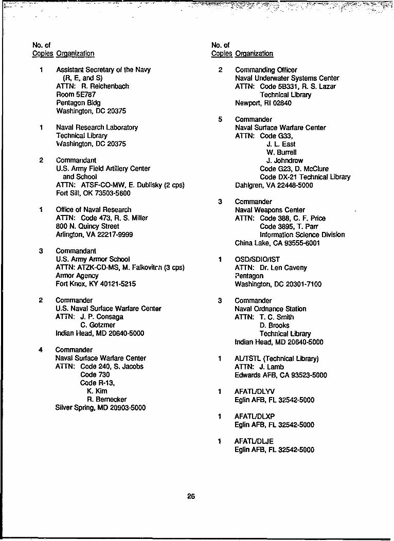
No. of No. ofCopies Oranization Copies Organization
Assistant Secretary of the Navy 2 Commanding Officer(R, E, and S) Naval Underwater Systems Center
ATTN: R. Reichenbach AiTN: Code 5B331, R. S. LazarRoom 5E787 Technical LibraryPentagon Bldg Newport, RI 02840Washington, DC 20375
5 CommanderNaval Research Laboratory Naval Surface Warfare CenterTechnical Library ATTN: Code G33,Washington, DC 20375 J. L. East
W. Burrell2 Commandant J. Johndrow
U.S. Army Field Artillery Center Code G23, D. McClureand School Code DX-21 Technical Library
ATTN: ATSF-CO-MW, E. Dublisky (2 cps) Dahlgren, VA 22448-5000Fort Sill, OK 73503-5600
3 CommanderOffice of Naval Research Naval Weapons CenterA'TN: Code 473, R. S. Miller ATTN: Code 388, C. F. Price800 N. Quincy Street Code 3895, T. ParrArlington, VA 22217-9999 Information Science Division
China Lake, CA 93555-60013 Commandant
U.S. Army Armor School 1 OSD/SDIO/ISTATTN: ATZK-CD-MS, M. Falkovitcn (3 cps) ATTN: Dr. Len CavenyArmor Agency PentagonFort Knox, KY 40121-5215 Washington, DC 20301-7100
2 Commander 3 CommanderU.S. Naval Surface Warfare Center Naval Ordnance StationA1T-N: J. P. Consaga ATTN: T. C. Smith
C. Gotzmer D. BrooksIndian Head, MD 20640-5000 Technical Library
Indian Head, MD 20640-50004 Commander
Naval Surface Warfare Center 1 AL/TSTL (Technical Library)ATTN: Code 240, S. Jacobs ATTN: J. Lamb
Code 730 Edwards AFB, CA 93523-5000Code R-13,
K. Kim 1 AFATLJDLYVR. Bemecker Eglin AFB, FL 32542-5000
Silver Spring, MD 20903-50001 AFATL/DLXP
Eglin AFB, FL 32542-5000
1 AFATIJDLJEEglin AFB, FL 32542-5000
26
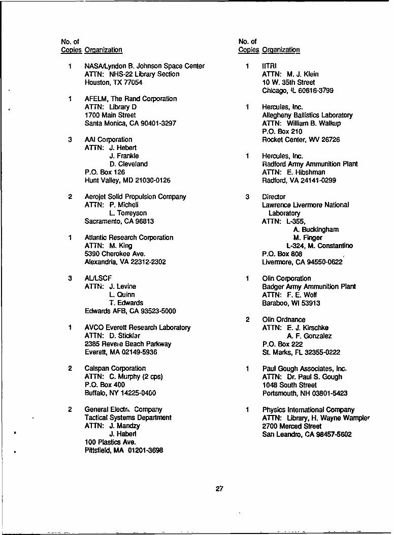
No. of No. ofCopies Omanization Copies Organization
NASA/Lyndon B. Johnson Space Center 1 IITRIAT'N: NHS-22 Library Section ATTN: M. J. KleinHouston, TX 77054 10 W. 35th Street
Chicago, IL 60616-3799AFELM, The Rand CorporationATTN: Library D 1 Hercules, Inc.1700 Main Street Allegheny Ballistics LaboratorySanta Monica, CA 90401-3297 ATTN: William B. Walkup
P.O. Box 2103 AAI Corporation Rocket Center, WV 26726
ATrN: J. HebertJ. Frankle 1 Hercules, Inc.D. Cleveland Radford Army Ammunition Plant
P.O. Box 126 ATTN: E. HibshmanHunt Valley, MD 21030-0126 Radford, VA 24141-0299
2 Aerojet Solid Propulsion Company 3 DirectorATTN: P. Micheli Lawrence Livermore National
L. Torreyson LaboratorySacramento, CA 96813 ATTN: L-355,
A. BuckinghamAtlantic Research Corporation M. FingerATTN: M. King L-324, M. Constantino5390 Cherokee Ave. P.O. Box 808Alexandria, VA 22312-2302 Livermore, CA 94550-0622
3 AULSCF 1 Olin CorporationATTN: J. Levine Badger Army Ammunition Plant
L. Quinn ATTN: F. E. WolfT. Edwards Baraboo, WI 53913
Edwards AFB, CA 93523-50002 Olin Ordnance
AVCO Everett Research Laboratory ATTN: E. J. KirschkeATrN: D. Sticklar A. F. Gonzalez2385 Reveie Beach Parkway P.O. Box 222Everett, MA 02149-5936 St. Marks, FL 32355-0222
2 Calspan Corporation 1 Paul Gough Associates, Inc.ATTN: C. Murphy (2 cps) ATTN: Dr. Paul S. GoughP.O. Box 400 1048 South StreetBuffalo, NY 14225-0400 Portsmouth, NH 03801-5423
2 General Electrk Company 1 Physics International CompanyTactical Systems Department ATTN: Ubrary, H. Wayne WamplerATTN: J. Mandzy 2700 Merced Street
J. Habed San Leandro, CA 98457-5602100 Plastics Ave.Pittsfield, MA 01201-3698
27
- - -~ - .- • ~- ' •-'---t-V•.-• • • -:•- -
No. of No. ofCopies Organization Copies Organization
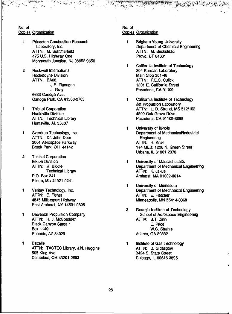
Princeton Combustion Research I Brigham Young UniversityLaboratory, Inc. Department of Chemical Engineering
ATTN: M. Summerfield ATTN: M. Beckstead475 U.S. Highway One Provo, UT 84601Monmouth Junction, NJ 08852-9650
1 California Institute of Technology2 Rockwell International 204 Karman Laboratory
Rocketdyne Division Main Stop 301-46ATTN: BA08, ATTN: F.E.C. Culick
J.E. Flanagan 1201 E. California StreetJ. Gray Pasadena, CA 91109
6633 Canoga Ave.Canoga Park, CA 91303-2703 1 California Institute of Technology
Jet Propulsion LaboratoryThiokol Corporation ATTN: L. D. Strand, MS 5121102Huntsville Division 4800 Oak Grove DriveATTN: Technical Library Pasadena, CA 91109-8099Huntsville, AL 35807
1 University of IllinoisSverdrup Technology, Inc. Department of Mechanical/IndustrialATTN: Dr. John Deur Engineering2001 Aerospace Parkway ATTN: H. KrierBrook Park, OH 44142 144 MEB; 1206 N. Green Street
Urbana, IL 61801-29782 Thiokol Corporation
Elkiun Division 1 University of MassachusettsATTN: R. Biddle Department of Mechanical Engineering
Technical Library ATTN: K. JakusP.O. Box 241 Amherst, MA 01002-0014Elkton, MD 21921-0241
1 University of MinnesotaVeritay Technology, Inc. Department of Mechanical EngineeringATTN: E. Fisher ATTN: E. Fletcher4845 Millersport Highway Minneapolis, MN 55414-3368East Amherst, NY 14501-0305
3 Georgia Institute of TechnologyUniversal Propulsion Company School of Aerospace EngineeringATTN: H. J. McSpadden, ATTN: B.T. ZinnBlack Canyon Stage 1 E. PriceBox 1140 W.C. StrahiePhoenix, AZ 84029 Atlanta, GA 30332
Battelle 1 Institute of Gas TechnologyATTN: TACTEC Library, J.N. Huggins ATTN: D. Gidaspow505 King Ave. 3424 S. State StreetColumbus, OH 43201-2693 Chicago, IL 60616-3896
28
No. of No. ofCopies Organization Copies Organization
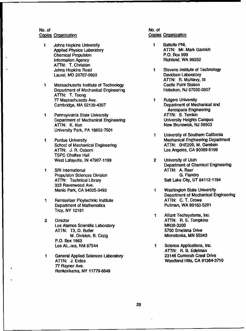
Johns Hopkins University 1 Battelle PNLApplied Physics Laboratory A'TN: Mr. Mark GamichChemical Propulsion P.O. Box 999Information Agency Richland, WA 99352ATTN: T. ChristianJohns Hopkins Road 1 Stevens Institute of TechnologyLaurel, MD 20707-0690 Davidson Laboratory
ATTN: R. McAlevy, IIIMassachusetts Institute of Technology Castle Point StationDepartment of Mechanical Engineering Hoboken, NJ 07030-5907ATTN: T. Toong77 Massachusetts Ave. 1 Rutgers UniversityCambridge, MA 02139-4307 Department of Mechanical and
Aerospace EngineeringPennsylvania State University ATTN: S. TemkinDepartment of Mechanical Engineering University Heights CampusATTN: K. Kuo New Brunswick, NJ 08903University Park, PA 16802-7501
1 University of Southern CaliforniaPurdue University Mechanical Engineering DepartmentSchool of Mechanical Engineering ATTN: OHE200, M. GersteinATTN: J. R. Osborn Los Angeles, CA 90089-5199TSPC Chaffee HallWest Lafayutte, IN 47907-1199 2 University of Utah
Department of Chemical EngineeringSRI International A'TN: A. BaerPropulsion Sciences Division G. FlandroATTN: Technical Library Salt Lake City, UT 84112-1194333 Ravenwood Ave.Menlo Park, CA 94025-3493 1 Washington State University
Department of Mechanical EngineeringRensselaer Ploytechnic Institute ATTN: C. T. CroweDepartment of Mathematics Pullman, WA 99163-5201Troy, NY 12181
1 Alliant Techsystems, Inc.2 Director ATTN: R. E. Tompkins
Los Alamos Scientific Laboratory MN38-3300ATTN: T3, D. Butler 5700 Smetana Drive
M. Division, B. Craig Minnetonka, MN 55343P.O. Box 1663Los Alt..aos, NM 87544 1 Science Applications, Inc.
ATTN: R. B. EdelmanGeneral Applied Sciences Laboratory 23146 Cumorah Crest DriveATTN: J. Erdos Woodland Hills, CA 91364-371077 Raynor Ave.Ronkonkama, NY 11779-6649
29
No. ofCopies Organization
1 Battelle Columbus LaboratoriasATTN: Mr. Victor Levin505 King Ave.Columbus, OH 43201-2693
1 Allegheny Ballistics LaboratoryPropulsion Technology DepartmentHercules Aerospace CompanyATTN: Mr. Thomas F. FarabaughP.O. Box 210Rocket Center, WV 26726
1 MBR Research Inc.ATTN: Dr. Moshe Ben-Reuven601 Ewing St., Suite C-22Princeton, NJ 08540
Aberdeen Proving Ground
1 Cdr, CSTAA'TN: STECS-PO, R. Hendricksen
30
USER EVALUATION SHEET/CHANGE OF ADDRESS
This laboratory undertakes a continuing effort to improve the quality of the reports itpublishes. Your comments/answers below will aid us in our efforts.
1. Does this report satisfy a need? (Comment on purpose, related project, or other area ofinterest for which the report will be used.)
2. How, specifically, is the report being used? (Information source, design data, procedure,source of ideas, etc.)
3. Has tne information in this report led to any quantitative savings as far as man-hours ordollars saved, operating costs avoided, or efficiencies achieved, etc? If so, pleaseelaborate.
4. General Comments. What do you think should be changed to improve future re[, rts?(Indicate changes to organization, technical content, format, etc.)
.RL Report Number BRL-TR-3300 Division Symbol
Check here if desire to be removed from distribution list.
Check here for address change.
Current address: OrganizationAddress
DEPARTMENT OF THE ARMY jjIIIDirector NO POSTAGEU.S. Army Ballistic Research Laboratory oONECESSARYATTN: SLCBR-DD-T MEDAberdeen Proving Ground, MD 21005-5066 IF MATLEDS.... .IN THE
OFFICIAL BUSINESS I BUS.T ESS REPLY MAIL UNTE STATES
IFIRSI CMAS FEWI ND 0001, AFG, M0OIiI
Postage will be paid by addressee . .. .
DirectorU.S. Army Ballistic Research LaboratoryATTN: SLCBR-DD-T _ _II
Aberdeen Proving Ground, MD 21005-5066 _