Embed Size (px)
Citation preview

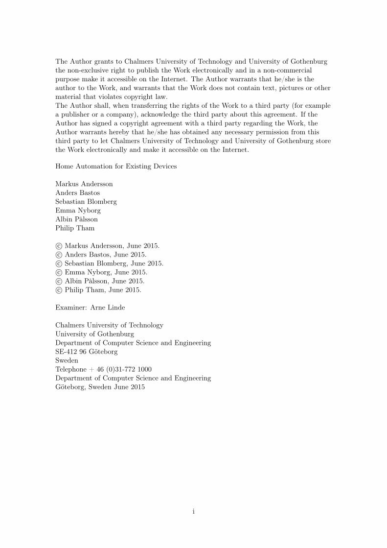
Home Automation for Existing Devices
Automating Non-Smart Devices Using Bluetooth Mesh Technology Controlled by Android Smartphones
Bachelor's of Science Thesis in Computer Science and Engineering
MARKUS ANDERSSONANDERS BASTOSSEBASTIAN BLOMBERGEMMA NYBORGALBIN PÅLSSONPHILIP THAM
Department of Computer Science and EngineeringCHALMERS UNIVERSITY OF TECHNOLOGYUNIVERSITY OF GOTHENBURGGothenburg, Sweden 2015
The Author grants to Chalmers University of Technology and University of Gothenburgthe non-exclusive right to publish the Work electronically and in a non-commercialpurpose make it accessible on the Internet. The Author warrants that he/she is theauthor to the Work, and warrants that the Work does not contain text, pictures or othermaterial that violates copyright law.The Author shall, when transferring the rights of the Work to a third party (for examplea publisher or a company), acknowledge the third party about this agreement. If theAuthor has signed a copyright agreement with a third party regarding the Work, theAuthor warrants hereby that he/she has obtained any necessary permission from thisthird party to let Chalmers University of Technology and University of Gothenburg storethe Work electronically and make it accessible on the Internet.
Home Automation for Existing Devices
Markus AnderssonAnders BastosSebastian BlombergEmma NyborgAlbin PålssonPhilip Tham
c© Markus Andersson, June 2015.c© Anders Bastos, June 2015.c© Sebastian Blomberg, June 2015.c© Emma Nyborg, June 2015.c© Albin Pålsson, June 2015.c© Philip Tham, June 2015.
Examiner: Arne Linde
Chalmers University of TechnologyUniversity of GothenburgDepartment of Computer Science and EngineeringSE-412 96 GöteborgSwedenTelephone + 46 (0)31-772 1000Department of Computer Science and EngineeringGöteborg, Sweden June 2015
i

Abstract
A growing topic in modern society is the concept of smart homes, which consist of smart
automated devices, such as home appliances, that interact with each other and users. These
devices could, however, be quite expensive, and automating a home could thus become an
economical setback. This Bachelor’s thesis examines how a home-automation system could
be developed to automate existing devices, providing them with smart technology, in a more
cost effective way rather than replacing them entirely.
The resulting home-automation system consists of adapters that enable existing non-
smart devices to be automated. Adapters have the ability to control power supply to an
existing device and interact with each other through a Bluetooth mesh network, allowing
for an extensible system. A user can control these adapters with an Android application,
either directly connected to the network of adapters, or through the Internet with the
help of a gateway installed in the network. Furthermore, the application provides several
utilities for managing the home-automation system and increasing user convenience.
Several features of the resulting home-automation system were evaluated by test
groups, and considered to be an improvement in their homes. Other features were consid-
ered to be of less importance and possibly causing inconvenience. The overall assessment
of the system was considered to be positive. However, there is room for improvement.
ii

Sammandrag
I dagens samhälle är smarta hem ett växande ämne. Konceptet med smarta hem går
ut på att kunna styra över apparater som kan kommunicera med varandra, exempelvis
smarta temperaturregulatorer eller fjärrstyrbara lampor. Dessa apparater kan dock vara
kostsamma, både i inköp och installation, vilket gör att många drar sig för att automatisera
sina hem. Denna rapport undersöker hur ett hemstyrningssystem, på ett kostnadseffektivt
sätt, kan utvecklas för att automatisera befintliga apparater utan att behöva ersätta dem.
Det utvecklade hemstyrningssystemet består av adaptrar som ger existerande icke-
smarta apparater möjlighet att autamatiseras. Adaptrarna har möjlighet att styra ström-
försörjningen till en existerande apparat, samt interagera med varandra över ett Bluetooth
mesh nätverk, vilket medför ett expanderbart system, där användaren kan utöka antal
adaptrar i systemet efter behov. Användaren kan styra dessa adaptrar med en Android-
applikation, antingen direkt ansluten till nätverket, eller genom Internet via en gateway
som då installerats i hemmet. Applikationen tillhandahåller ett antal verktyg för att
hantera hemstyrningssystemet, vilka gynnar bekvämligheten för användaren.
Utvärderingar, gjorda i testgrupper, visade att flera egenskaper i det resulterande
hemstyrningssystemet bidrog till förbättringar i användarnas hem. Andra egenskaper
visade sig vara mindre betydelsefulla och bidrog i vissa fall även till besvär för använ-
daren. Den resulterande bedömning av systemet visade ett överlag positivt intryck, dock
finns det utrymme för förbättringar.
iii

Acknowledgment
We would like to thank Lennart Hansson for his guidance, expertise and time spent on
this project. We would also like to express gratitude towards those who participated in
our survey and tested our prototype.
iv

Contents
List of Abbreviations vii
1 Introduction 11.1 Purpose . . . . . . . . . . . . . . . . . . . . . . . . . . . . . . . . . . . . . . 11.2 Scope . . . . . . . . . . . . . . . . . . . . . . . . . . . . . . . . . . . . . . . 21.3 Method . . . . . . . . . . . . . . . . . . . . . . . . . . . . . . . . . . . . . . 21.4 Outline . . . . . . . . . . . . . . . . . . . . . . . . . . . . . . . . . . . . . . 2
2 Preliminary Survey 42.1 Results . . . . . . . . . . . . . . . . . . . . . . . . . . . . . . . . . . . . . . . 42.2 Discussion and Conclusion . . . . . . . . . . . . . . . . . . . . . . . . . . . . 5
3 Hardware 63.1 Controlling High Voltage with Low Voltage . . . . . . . . . . . . . . . . . . 63.2 Controlling the Brightness of a Lamp . . . . . . . . . . . . . . . . . . . . . . 73.3 Results . . . . . . . . . . . . . . . . . . . . . . . . . . . . . . . . . . . . . . . 83.4 Discussion . . . . . . . . . . . . . . . . . . . . . . . . . . . . . . . . . . . . . 8
4 Network 104.1 Network topologies . . . . . . . . . . . . . . . . . . . . . . . . . . . . . . . . 104.2 Network Protocols . . . . . . . . . . . . . . . . . . . . . . . . . . . . . . . . 11
4.2.1 Wi-Fi . . . . . . . . . . . . . . . . . . . . . . . . . . . . . . . . . . . 114.2.2 ZigBee . . . . . . . . . . . . . . . . . . . . . . . . . . . . . . . . . . . 114.2.3 Ant . . . . . . . . . . . . . . . . . . . . . . . . . . . . . . . . . . . . 124.2.4 Bluetooth Low Energy . . . . . . . . . . . . . . . . . . . . . . . . . . 124.2.5 Broadcast Storm . . . . . . . . . . . . . . . . . . . . . . . . . . . . . 14
4.3 Results . . . . . . . . . . . . . . . . . . . . . . . . . . . . . . . . . . . . . . . 144.3.1 Simple BLE Mesh Network . . . . . . . . . . . . . . . . . . . . . . . 154.3.2 Node Applications . . . . . . . . . . . . . . . . . . . . . . . . . . . . 184.3.3 Connecting a Central . . . . . . . . . . . . . . . . . . . . . . . . . . . 18
4.4 Discussion . . . . . . . . . . . . . . . . . . . . . . . . . . . . . . . . . . . . . 19
5 Android Application 225.1 Android API . . . . . . . . . . . . . . . . . . . . . . . . . . . . . . . . . . . 225.2 Three-tier Architecture . . . . . . . . . . . . . . . . . . . . . . . . . . . . . . 225.3 Results . . . . . . . . . . . . . . . . . . . . . . . . . . . . . . . . . . . . . . . 235.4 Discussion . . . . . . . . . . . . . . . . . . . . . . . . . . . . . . . . . . . . . 27
6 Cloud Server 286.1 Web Service Architecture Styles . . . . . . . . . . . . . . . . . . . . . . . . . 28
6.1.1 Representational State Transfer . . . . . . . . . . . . . . . . . . . . . 286.1.2 Simple Object Access Protocol . . . . . . . . . . . . . . . . . . . . . 28
6.2 Server Back-End Solutions . . . . . . . . . . . . . . . . . . . . . . . . . . . . 296.3 Results . . . . . . . . . . . . . . . . . . . . . . . . . . . . . . . . . . . . . . . 296.4 Discussion . . . . . . . . . . . . . . . . . . . . . . . . . . . . . . . . . . . . . 31
v

7 Gateway 337.1 Results . . . . . . . . . . . . . . . . . . . . . . . . . . . . . . . . . . . . . . . 337.2 Discussion . . . . . . . . . . . . . . . . . . . . . . . . . . . . . . . . . . . . . 34
8 User Tests 368.1 Results . . . . . . . . . . . . . . . . . . . . . . . . . . . . . . . . . . . . . . . 368.2 Discussion . . . . . . . . . . . . . . . . . . . . . . . . . . . . . . . . . . . . . 37
9 Results 38
10 Discussion 40
11 Conclusion 41
References 42
vi

List of Abbreviations
AC Active Current
ACK Acknowledgement
AI Artificial Intelligence
AP Access Point
API Application Programming Interface
BLE Bluetooth Low Energy
DC Direct Current
GAP Generic Access Profile
GATT Generic Attribute Protocol
GUI Graphical User Interface
HTTP HyperText Transfer Protocol
IDE Integrated Development Environment
IoT Internet Of Things, a term for everyday devices having an embedded computerwith the ability to represent itself and communicate intelligently with others in anetwork
JSON JavaScript Object Notation
LED Light-Emitting Diode
MANET Mobile Ad Hoc Network
MVC Model, View, Controller. A design pattern for developing software with user inter-face
Opcode Operation Code
ORM Object-relational Mapping
OSI Open Systems Interconnection
REST Representational State Transfer
RSSI Received Signal Strength Indication
SBC Single Board Computer
SBMN Simple BLE Mesh Network
SOAP Simple Object Access Protocol
SSL Secure Socket Layer
vii

UI User Interface
URI Uniform Resource Identifiers
URL Uniform Resource Locator
WSDL Web Service Description Language
XML Extensible Markup Language
viii

1 INTRODUCTION
1
Introduction
Home automation is the concept of controlling and automating the use of home appliancesand other electrical equipment, such as light bulbs, temperature gauges or door locks.The topic of home automation is nothing new. In fact, computer based systems weredeveloped already in the 1960s [1]; however, there has not been any wide scale breakthroughuntil recently. According to Berg Insight, a market research firm based in Sweden, therewere approximately 2.9 million smart homes [2], i.e. homes with automation technologycontrolled by a computer, in the U.S. 2012. Furthermore, the installed base is expected toreach 31.4 million by 2017 [2], potentially increasing economical and technical interests.
The concept Internet Of Things (IoT) can be closely tied together with home au-tomation. IoT devices, such as smart thermometers, can be controlled by, for example,a smartphone and thus possibly providing worldwide range through the Internet. Thesedevices together with the rising popularity of the smartphone [3] account for one of thereasons to the increase in home automation. Home automation with IoT devices providesgreat convenience and means of optimizing energy consumption by, for example, enablingautomatic energy saving or presenting power consumption data to a user in real time.However, it could become expensive if conventional devices were to be replaced by theirIoT equivalents. Therefore, when converting to a smart house, a major issue is making allnon-IoT devices compatible with a home-automation system [4]. Gill et al. [5] identify theintrusiveness of installations as one of the areas that have hindered consumer adoption ofhome automation technologies. Consequently, converting non-IoT devices should be donein a manner such that a user would easily be able to install a system, without the need tomake hardware changes in the house.
IoT devices also have their drawbacks, mainly in the way they communicate witheach other. According to Gill et al. [5] the interoperability between home automationtechnologies, such as the vast use of different communication protocols, is one of the majorfactors impeding consumer adoption of home-automation system. Therefore, in an idealhome-automation system, the communication protocols used should preferably be thosesupported by common consumer devices, in order to provide maximum compatibility.
This section further explains the purpose of creating a concept for automating ex-isting home appliances and electrical devices.
1.1 Purpose
The purpose of this project is to develop a concept and a prototype of a smart power controlsystem that allows for scalable home automation and can be used to operate existinghome appliances and electrical equipment. The concept aims to increase the convenienceof controlling home appliances for a broad audience, by being simple to install, maintain,and use.
1

1.2 Scope 1 INTRODUCTION
1.2 Scope
This project aims to create a concept for a home-automation system with the use ofexisting technologies. Control of a vast area of existing devices should be taken intoconsideration; however, as a limitation of the prototype, only functionality to control powersupply to existing devices will be implemented. In order for users to control the system,this project will develop an Android application; however, aesthetics of this applicationwill not be prioritized, as functionality is considered of higher importance. Furthermore, ahome-automation system could involve features such as artificial intelligence (AI) or powermeasuring capabilities, but this is beyond the scope of this project. However, this projectwill attempt to implement simple automation functionality that could be beneficial to theuser. Security aspects are also taken into consideration, but will not be implemented dueto time restrictions.
1.3 Method
In order to make the purpose applicable and practicable to implement, specifics regardingwhat should be done needed to be gathered. Therefore, a preliminary survey was conductedwith the intent of gaining perspective of the current home automation needs. The par-ticipants were asked questions regarding previous knowledge of home automation-systemsand to give feedback on desired system features.
Based on the result of the preliminary survey, research was conducted on availabletechnologies and utilization of these. Development was logically divided into several sub-areas, which were relatively independent of each other. Each project group member wasassigned to mainly work on and be responsible for one such sub-area. This allowed differentgroup members to work in parallel in a structured way.
When the project group believed the product to be in a sufficient state, user testswere conducted to evaluate the result of the project. Each participant was handed anumber of prototype units, as well as the Android application. When the test period wasover, the participants evaluated the system by answering a set of questions in the form ofa survey.
1.4 Outline
The development of this project was divided into five fields: Hardware, Network, Android,Cloud Server and Gateway. This division is reflected in the thesis accordingly and illus-trated in figure 1. Each section in this thesis describes the methods and theory, as well asthe resulting research, conclusions and discussions of each field. Moreover, these sectionsare ordered in a bottom-up perspective, presenting the most fundamental fields first.
2

1.4 Outline 1 INTRODUCTION
Figure 1: Illustration of the different sections of the project. The hardware (circles in the household), the network(connecting the circles), the Android application (the sender), the cloud server, and the gateway.
The Hardware chapter describes the methods and results of creating hardware ableto control existing devices. Furthermore, in the Network section, the communication pro-tocol used to connect these adapters is presented and discussed. The Android Applicationchapter presents the interface to which the user can control the system. Furthermore, theCloud Server chapter introduces methods for backing up and synchronizing informationused in the application. The Gateway chapter describes opportunities for connection be-tween an end-user at a distant location and the home-automation system. Finally, theUser Tests chapter presents the results and discussion of the evaluation of the system.
3

2 PRELIMINARY SURVEY
2
Preliminary Survey
To gain knowledge of a consumer’s perspective of current home-automation systems and thepotential needs of future systems, a preliminary survey was conducted. Statistics Sweden,a government-managed administrative agency, reports that 50% of the Swedish populationlive in proprietary houses, 15% in condominiums, and 25% in rental apartments [6]. Thesurvey was distributed to twenty persons of different gender and age of the product’starget audience. The participants were chosen by type of housing to reflect the housingtype distribution of Swedish citizens.
Four topics received focus in the survey: user friendliness, scalability, accessibility,and convenience. Participants were asked to answer whether they had any previous home-automation system, and if so their experience with these systems. Moreover, participantswere asked to give feedback on potential desires for system features, with regards to thefour topics mentioned above.
2.1 Results
With regards to accessibility and scalability, the survey showed that all the participantsestimate the average distance between their home appliances to be less than 10 meters.Furthermore, participants living in houses estimated that the longest distance betweenthem and any device in their homes was less than 20 meters. The corresponding distance,answered by participants living in apartments, is estimated to be between 1 and 10 meters.Additionally, controlling devices from a distant location (outside of the property area),proved to be a desired feature amongst 50% of the participants of the survey. 30% expresseddesire to have the ability of scheduling events, 10% expressed desire to have environmentalfunctionalities such as energy saving based on the brightness of daylight, or monitoringpower usage, as illustrated in figure 2.
Figure 2: Graph showing the features desired by the survey participants.
4

2.2 Discussion and Conclusion 2 PRELIMINARY SURVEY
In reference to convenience and user friendliness, the survey revealed that the mainreasons for not acquiring a home-automation system are: expenses (43%), complexityof installing and using it (29%), and lack of usefulness (14%). Moreover, 23% of theparticipants expressed that the most inconvenient factor of having a home-automationsystem is the often required excessive devices, such as remote controls. Almost 40% of theparticipants also found the expansion of current systems problematic.
2.2 Discussion and Conclusion
The survey revealed that one of the most prominent flaws in existing home-automationsystems is the inconvenience of having to use excessive devices. Furthermore, these de-vices, such as remote controls, may be inaccessible at times. A solution for this could beto integrate controlling software into a smartphone, as the majority of the inhabitants inSweden own such a device [7] and is likely to carry it with them at most times. There-fore, our system will be controlled via smartphones. An application will be developed forAndroid as it is currently the most used smartphone operating system [8]. Developing anapplication allows for greater flexibility in dynamically presenting system components, ascompared to a fixed layout of a hardware remote control.
To satisfy the interest of controlling a home-automation system from distant loca-tions, remote access to the system through the Internet will be implemented. This allowsfor greater accessibility and convenience. The Android application must allow seamless in-tegration of both on-site and off-site controlling, through the use of a gateway that bridgesthe system functionality to the Internet. However, as scalability is of importance, thisgateway should be optional, i.e. the system should also work without a gateway, but in amore limited capacity.
Furthermore, the survey showed that the range between a user and any device couldexceed 20 meters, meaning that the network connecting automated devices should beavailable to the user and exceed 20 meter in range in any direction from the user.
Although participants expressed interest in environmental functionalities, imple-menting such features is not prioritized in this project, as the main purpose is to developa functioning prototype. However, all components will be developed with consideration ofsuch features for potential future implementation.
With these results in mind, this project will examine how to develop a home-automation system that effectively fulfills the four criteria: user friendliness, scalability,accessibility and convenience. The developed prototype should be convenient and easy touse, as well as add useful functionality to the everyday life of consumers. It is also ofhigh importance that the system is designed in such matter that new devices can easily beadded and remain connectable. Furthermore, all devices should be able to be controlledby the user’s smartphone in a radius of 20 meters. Lastly, the user needs to be able tocontrol the system remotely, over the Internet.
5

3 HARDWARE
3
Hardware
The most fundamental part of a home-automation system is the hardware of the automateddevices. As the purpose of this project is to enable IoT functionality for non-smart existingdevices, hardware that connects existing devices with the system was developed. There aremany ways to enable IoT functionality for existing devices, for example building hardwarethat regulates temperature, opens curtains or measures power consumption. To limit thescope of the project a limitation was enforced to only build hardware, with networkingcapabilities, that enables control of power supply to existing devices, such as lamps orcoffeemakers. During this project, two types of power controllers, a power switch anda dimmer, were designed and constructed. From here on out, these power controllersare referred to as adapters. This section describes different methods for controlling highvoltage current with hardware solutions, and the results and discussion of the outcome.
3.1 Controlling High Voltage with Low Voltage
Most electronic consumer devices, if connected to a power grid, run on high voltage alter-nating current (AC). According to Worldstandards.eu [9], the majority of national powergrids in the world supply 220-240 V with a frequency of either 50 or 60 Hz. To control highvoltage AC through the use of low level direct current (DC), a power switch componentutilizing galvanic isolation between the two currents is required. With such a component,a microcontroller, which uses low level DC, can control high voltage AC. Traditionally, anelectromechanical relay is used for this purpose. An electromechanical relay is a powerswitch toggled by an electromagnet, driven by low voltage current. Furthermore, electro-magnetic relays can be divided into two categories: latching and non-latching. Non-latchingrelays requires a low current, driving the electromagnet, to keep its high voltage circuitclosed [10]. As soon as the low current disappears, the non-latching relay breaks its circuit.In contrast, latching relays require only a quick power pulse to close its circuit. Once closedthe latching relay will break its circuit only if another power pulse is received, hence itdoes not require a constant current to keep its circuit closed. As a consequence, latchingrelays are widely used in applications where low power consumption is prioritized [10]. Incomparison to non-latching relays, latching relays tend to be quite expensive.
In addition to relays, there are other components that can be used to control highvoltage current. A triac is a bidirectional thyristor that allows a high voltage AC to becontrolled by lower AC [11, p. 498]. Compared to a mechanical relay, a triac does not haveany mechanical parts and is therefore able to switch faster. To achieve galvanic isolation,an optically isolated (Optocoupler) triac driver can be used. By running a low level DCthrough the optocoupler, a light-emitting diode (LED) produces light which toggles anisolated light sensitive transistor or thyristor to let a high voltage current through to thetriac [12].
6

3.2 Controlling the Brightness of a Lamp 3 HARDWARE
3.2 Controlling the Brightness of a Lamp
Sometimes it is desirable to control the amount of power going to a device, for example tocontrol the brightness of a lamp, rather than just turning the power on or off. A commonmethod to do so is Phase-Control, in which the sinusoidal wave form of an alternatingcurrent is partially removed or cut off [13, p. 3], as illustrated in figure 3. Removing partsof the sinusoidal wave reduces the voltage root-mean-square Vrms of the waveform, whichmakes the power output lower. The smaller the area under the sinusoidal wave, the lowerVrms. Phase-Control can be achieved by using a triac, which is able to toggle 100 timesper second required by an AC at 50 Hz.
For the power output to remain stable, cutting needs to take place at the same timefor each wave. Therefore, a point of reference is needed. The natural point of referenceis the zero crossing point of the sinusoidal wave and cutting from the it is called leadingedge cutting [13], illustrated in figure 3. Leading edge cutting allows for the controllingof resistive loads [14], such as light bulbs, and inductive loads, such as electrical engines.Another way of cutting the sinusoidal wave is trailing edge cutting, illustrated in figure 3.Compared to leading edge cutting, trailing edge cutting cuts the latter part of a halfperiod. Trailing edge allows for resistive loads [14] and capacitive loads, such as electricaltransformers. When dimming incandescent light bulbs or halogen lamps, both approacheswork, as they can both control resistive loads. However, in the case of dimmable LED lampsthe method which should be used depends on the specification of the LED lamps [13]. SomeLED lamps only allows for leading edge cutting, and others only for falling edge cutting.There does not seem to be a clear standard.
Figure 3: Illustration of an unmodified AC sinusoidal wave (top) and an AC that has been modified using leadingedge Phase-Control (middle), and an AC that has been modified using trailing edge Phase-Control (bottom). Asillustrated, Phase-Controll reduces the Vrms.
7

3.3 Results 3 HARDWARE
3.3 Results
The simplest form of controlling power to an existing device is by a power switch. Ourdesign of the power switch adapter developed in this project uses a timer casing, as seen infigure 4a. This allows a user to plug the adapter into a power socket, and a device directlyinto the socket of the timer casing. Furthermore, our design includes an electronic circuit,which consists of a non-latching relay to toggle the high voltage AC, a transistor to togglethe relay, an AC/DC transformer to power the circuit, as well as other components specifiedin Appendix D. The power switch circuit is built to be operated by a microcontroller, withone of its pins connected to the transistor, thus enabling control of the relay.
Similar to the power switch adapter developed in this project, our dimmer adapterdesign also uses a timer casing, as can be seen in figure 4b. However, instead of using a relay,the dimmer adapter uses a triac to perform leading edge Phase-Control, thus controllingthe amount of power to the connected device. The dimmer circuit is based on diy_bloke’sreference design [15] and built primarily to control the brightness of a lamp (for furtherreference see appendix H). To perform phase control, the dimmer adapter circuit includesa zero crossing mechanism which toggles the pin of a dedicated microprocessor, Atmel’sATtiny85. Our program running on the ATtiny85 turns on the triac, via a triac driver,on every zero crossing indication. Based on a brightness level B ∈ [0.255], the programthen turns off the triac after B·d
255 seconds, where d is the duration of half a wavelength.The value of d is static and needs to be changed according to the frequency of the powergrid the dimmer adapter is to be used with. The program running on the ATtiny85 allowscommunication with other microcontrollers using UART, a well established protocol forserial communication [16]. Through UART, other microcontrollers can transmit a newbrightness value b which the program running on the ATtiny85 will accept and obey.
Figure 4: The two types of adapters designed for the project. The left (a) illustrates a power switch adapter. Theright (b) illustrates a dimmer adapter.
3.4 Discussion
The limitation of only building adapters for controlling high-voltage power supply is dueto two reasons. Firstly, the adapters are applicable to most types of existing devices andthus allow control of multiple devices by simply regulating power supply. Secondly, inconsideration of the time limitations of this project, the adapters were simple to construct.Furthermore, the dimmer was developed only to be used with lamps, as a study performed
8

3.4 Discussion 3 HARDWARE
by the Lightning Research Center [17, p. 2] shows an energy saving of 6% from manualdimming. Thus by enabling dimming remotely, the system could potentially reduce thepower consumption of a home.
Our power switch adapter design uses a non-latching relay, as opposed to a latchingrelay. The main reason for this is the increased cost a latching relay would have contributedto. However, a latching relay would have been preferable to a non-latching relay in anenvironmental aspect, as it only consumes a fraction of the power of a non-latching relay.Furthermore, we did not consider using a triac instead of a relay in the power switchadapter. A triac could potentially minimize the design, although we have not investigatedany potential side effects this may cause.
While using a timer casing provides easy means of encasing a circuit, it also leavesmuch unused space. Our adapter designs could therefore be minimized, allowing for betteruse in, for example, power strips. Furthermore, in an ethical aspect, our design does notfully isolate high voltage AC from a user, since the circuit is fully exposed. This, of course,needs to be addressed if the prototypes were to be put into production. Moreover, theform factor of a timer casing is not ideal in all cases. One might imagine an adapter thatfits right into a light bulb socket instead of a standard wall socket, thus enabling easierinstallations in ceiling lamps.
Our dimmer adapter design uses leading edge Phase-Control to dim a light bulb. Asthe dimmer adapter is intended to be used to control the brightness of a lamp, and bothleading edge and falling edge Phase-Control can be used to so, it would have worked withfalling edge Phase-Control as well. Leading edge Phase-Control is however able to controlinductive loads, thus allowing users to control the speed of electric motors in devices suchas a fan. Controlling inductive loads may be useful in a home-automation system, howeverour dimmer design would require minor changes to allow for this, as it was designed onlyto be used with resistive loads, such as lamps.
As opposed to changes in hardware, the dimmer functionality could be improved bya simple software change. As described in the result section, the duration value d mustbe statically programmed into the microprocessor. To avoid this, an initialization routinecould be written, logging the time between zero crossings for 1 second. The resulting logscan then be used to automatically calculate the frequency of the national power grid.
9

4 NETWORK
4
Network
A fundamental part of a home-automation system is the network that connects the auto-mated devices with each other, as well as the user. This can be done in many different waysby using different structures and communication protocols. This chapter will examine howa network can be designed and implemented in order to achieve desired features, and theresult.
4.1 Network topologies
The first matter to consider is how the devices connect to each other and how to controlthem. Every network can be said to have a topology. Some of the most common networktopologies are the Star and Mesh-topologies [18, p. 10]. In a Star topology every node isconnected to, and communicates through, a central hub, which relays messages to theirdestinations, as illustrated by figure 5a. In a Mesh topology every node is directly connectedto every other node, enabling direct communication. Furthermore, there is a variation ofthe Mesh topology, known as the Hybrid Mesh topology, in which there exists a pathbetween every node. However, not every node is connected with every other else, asillustrated by figure 5b.
Figure 5: The left illustration (a) depicts a star topology, where devices (green nodes) are dependent on a central hub(blue node) for communicating. The right illustration (b) depicts a mesh topology, where every node is connectedto every other node, eliminating the need for a central hub. This allows the sending node (blue) to communicatewith the receiving node (red).
In addition to being defined by a topology, wireless networks can also be categorizedby the number of hops (single or multiple) required to transmit a message [19]. In single-hopwireless networks the communicating devices are within range of one another and transmitdirectly (forming a star or point-to-point topology). In contrast, communication in multi-
10

4.2 Network Protocols 4 NETWORK
hop wireless networks may be relayed by intermediary nodes, enabling communicationbetween out of range devices. Such networks are referred to as wireless mesh networks [19].
Each wireless network can be categorized as either infrastructure-based or infrastructure-less. In an infrastructure-based wireless network a base station is in place which connectsand handles communication throughout the network, as well as to neighbouring networks.In contrast, an infrastructure-less wireless network must coordinate communication in adistributed fashion.
4.2 Network Protocols
There are several different networking technologies that utilize different topologies, whichcould be used to implement communication in a home-automation system. Some arepurpose-built to be used in distributed environments and consume little energy, but arenot widely supported; others may be widely supported but are not suitable for home-automation systems.
Gill et al. identifies “the complexity and expense of the architectures adopted byexisting systems” and “the intrusiveness of the system installations” [5] as two of the mainreasons that have impeded consumer adoption of home-automation systems technologies.When choosing networking technologies, these reasons must be taken into account. Tomake the installation as non-obstructive as possible, a wireless network technology wouldbe preferable compared to a wired one. The ideal technology would also allow usage withoutthe need for excessive devices, such as adapters for smartphones or range extenders, whichincreases the complexity and expense of a system. This section describes four differenttechnologies and previous applications in related fields.
4.2.1 Wi-Fi
IEEE 802.11, more commonly know as Wi-Fi, is a widely used wireless network protocoldesigned for short range high speed communication between devices ranging up to a fewhundred meters [20, p. 12], depending on the protocol version and external factors. Thelatest standard, 802.11ac, offers a data transfer rate of up to 1300 Mb/s [21, p. 3]. Dueto the high speed communication, the current power consumption of Wi-Fi devices canbe regarded as relatively high. Recently, however, low power Wi-Fi modules have becomeavailable that offer significantly lower power consumption. According to the datasheet ofone such device, the RN-131G, the active power consumptioncurrent usage is between 40mA (receiving) and 210 mA(transmitting) [22, p. 2].
Wi-Fi is a single-hop infrastructure-based technology utilizing a star topology withan access point (AP), as base station. However there is an amendment to the 802.11standard called 802.11s which enables an infrastructure-based multi-hop mesh networkingfunctionality [23]. An 802.11s network consists of several mesh access points (MAP), thatcommunicate and relay messages amongst themselves. Every MAP also grants clientsaccess to the mesh network, consequently only allowing the clients to communicate with aMAP, and not with other clients.
4.2.2 ZigBee
A fairly new wireless network protocol, well suited to home-automation systems [5] , isZigBee. Utilizing radio frequency at three bands [24], 2.4 GHz, 912 MHz, 868 MHz, theZigBee protocol is designed to provide a responsive network with fast transmissions. How-ever, the protocol also restricts the data rate to 250 kb/s, 40 kb/s and 20 kb/s for respective
11

4.2 Network Protocols 4 NETWORK
frequency. This type of design gives the advantage of miniscule power consumption. More-over, ZigBee natively supports both the mesh and star topologies, allowing the formationof either a single or multi-hop wireless network.
Despite the appealing factors of ZigBee, the technology has drawbacks, mainly itslack of native support in most consumer devices such as smartphones. To directly controla ZigBee network from a smartphone, additional hardware, an adapter, must be installed.Gill et al. [5, p. 426] proposes building a gateway, bridging a Wi-Fi network with a ZigBeenetwork, thus removing the need for an adapter in every smartphone, while also enablingaccess to the Internet. However, such a gateway also presents challenges. Firstly, thereis the issue of how to easily configure it to work on an existing Wi-Fi network. Secondly,Gill et al. [5, p. 428] discovered that the average access delay doubled when using Wi-Fi, compared to using ZigBee directly. Thirdly, a gateway limits the access range of thenetwork to that of the Wi-Fi network, thus removing some of the advantages of ZigBee’smesh topology.
4.2.3 Ant
Another short range, low power, wireless network protocol is Ant. Mostly found in sportsgear today, Ant is designed to run on small power sources and mainly to be used asa wireless sensor network, thus employing low data rate transmissions. Ant has beendesigned to work within ranges of 30 meters, given clear line of sight [25].
Similar to ZigBee, Ant also natively supports the mesh and the star topologies.However, unlike ZigBee, Ant is natively supported by some high-end Android smartphones,but not any iPhone model [26]. Thus, a major part of all smartphones still requiresadditional hardware to connect to an Ant network.
4.2.4 Bluetooth Low Energy
Bluetooth is a wireless technology developed to replace cables between electrical deviceswithin short range [27, p. 17]. Bluetooth low energy (BLE), or Bluetooth v4.0, is currentlythe latest major Bluetooth standard introduced by the Bluetooth Special Interest Group.This standard is intended to support low hardware development costs and, especially, lowpower consumption. The technology is optimized to be powered by small power sources,such as coin cell batteries [28]. According to the datasheet of one such commonly useddevice, Texas Instruments’ CC2540, the active power consumption is between 19.6 mA(receiving) and 24 mA (transmitting) [29, p. 1]. However, studies show that the averagepower consumption of the CC2540 is less than 0.1mA in a normal scenario, with energysaving enabled [30]. Moreover, the BLE standard imposes no range limitations [28], butmost Bluetooth devices have a range of 10 meters.
Bluetooth is a single-hop infrastructure-less technology utilizing a star topology.Every Bluetooth device can either be a master (central) that initiates connections, or aslave (peripheral) that accepts connections. In BLE these are called Generic Access Profile(GAP) roles and communication is only permitted in a connection between a master anda slave. Within an established connection, communication is regulated by the GenericAttribute Protocol [27, p. 519](GATT). This protocol utilizes a service, intended to supporta specific feature, such as a heart rate monitor or temperature sensor. Communicationbetween devices is performed via characteristics [27, p. 529], which are data fields accessiblefrom both parts of a connection, declared in the GATT service. By writing to and readingfrom these fields two devices are able to communicate.
12

4.2 Network Protocols 4 NETWORK
Before transferring data, a designated master initiates connections with up to sevenslaves, forming a star topology known as a piconet. Similarly to Wi-Fi, Bluetooth doesnot natively support mesh topologies. However, research has shown a possibility of com-bining several piconets to form a scatternet (mesh topology), thus forming a multi-hopinfrastructure-less mesh network, as illustrated by figure 6. In a scatternet at least oneslave in every piconet also participates as a slave in another piconet, and thereby enablesrelaying of messages between piconets. A major topic of research is formation of scat-ternets, i.e. how to distributedly designate masters and relay slaves. There are severalmethods for forming scatternets including MTFS [31], BlueTrees [32] and BlueStar [33].MTFS, developed by Sunkavalli and Ramamurthy, compared to BlueTrees and BlueStar,is a distributed formation algorithm, thus the scatternet formation delay is independentof the number of nodes, and is on average 7 seconds for a network with 0.2 nodes/m2 [31,p. 3598]. Using a smartphone, which is often a master, in such a scatternet could thereforeentail a few seconds delay during formation or changing the topological layout throughgeographical relocation.
Figure 6: Combining several piconets forms a scatternet, allowing for a multi-hop infrastructure-less mesh network.
Bluetooth Low Energy enables communication without having an established con-nection, by using advertisements. BLE advertisements are broadcasts sent from a deviceand are available to any other device, within range, scanning for advertisements. In supportof advertisements, BLE introduced the two roles of Broadcaster and Observer, in additionto the already existing slave/peripheral and master/central roles. Both Broadcaster andObserver are limited to one-way communication through advertisements: the Broadcasteronly sending advertisements on a regular interval, and the Observer only scanning for ad-vertisements. However, these roles can be combined with the central or peripheral role,to enable connection functionality. Advertising is however limited in the amount of data,carried in one advertisement packet [27, p. 389]. The maximum length of the data carriedin an advertising packet is 31 bytes.
Through the use of advertisements, T. Snekvik of the Norwegian University of Scienceand Technology, has developed the nRF51-ble-broadcast-mesh [34], which is a connection-less based Bluetooth mesh protocol for Nordic Semiconductor’s nRF51 series. Comparedto a scatternet, which requires the establishment of connections, the nRF51-ble-broadcast-
13

4.3 Results 4 NETWORK
mesh has no notable formation delay and is not affected by any changes in topology struc-ture. Instead the broadcast mesh works by flooding every message to every node throughadvertising channels on which everyone can receive. The mesh network has a global state,containing some values, and all nodes in the network have a local state copy of the globalstate. Whenever a value change has been observed, each node relays the change to the restof the network, thus synchronizing its local state with the global mesh network state. Asa consequence of communicating via advertisements, the maximum data size per value, inthe mesh network, is 28 bytes [35], which may not suffice in some cases.
Normally, communication is done only in a connection. Within an established con-nection BLE utilizes Generic Attribute Protocol [27, p. 519], GATT, a communicationprotocol and service framework controlling the communication flow between devices. Thecommunication is regulated with the use of a GATT Service, which is a service intendedto support a specific feature, such as a heart rate monitor or temperature sensor. Commu-nication between devices is performed via a concept known as characteristics, declared inthe GATT service. A characteristic [27, p. 529] is a data field, provided with a definitiondescribing properties, descriptors and permissions, accessible from both parts of a connec-tion. By writing to and reading from these fields two devices are able to communicate witheach other.
4.2.5 Broadcast Storm
In a mesh network that uses a flooding technique, a Broadcast storm could occur. Broad-cast storm is a phenomenon where several nodes in a network attempt to uncontrollably for-ward messages by flooding, often resulting in severe redundancy and collisions [36, p. 151].Ni et al. [36] introduced several mechanisms: Probabilistic scheme, Counter-based scheme,Distance-based scheme, Location-based scheme and Cluster-based scheme, to prevent thisphenomenon in a Mobile Ad Hoc Network (MANET). All of these schemes attempt to limitforwarding of redundant broadcasts. Ni et al. found their location-based scheme, whichlimits forwarding based on location, to be the most effective. It reduces up to 50% [36,p. 159] of redundant forwardings, while maintaining about 95% accessibility in a 5r x 5rarea containing 100 nodes (where r is the transmission radius). However, this schemerequires location information about each individual node, which may not always be avail-able. The Counter-based scheme [36, p. 155], does not require any location information,but instead makes use of a random backoff mechanism, in which every node waits for arandom amount of time before forwarding a message m. During this wait, a counter cis incremented every time the same message m is received. If c reaches above a counterthreshold C, the forwarding of message m is canceled. A lower threshold value C decreasesthe number of redundant advertisements in dense areas, but also decreases the accessibilityin non-dense areas, whereas a high C-value has the opposite effect. Ni et al. found theircounter-based scheme to decrease the number of forwardings by about 30% [36, p. 158],while maintaining a reachability of close to 100%, in a 5r x 5r area containing 100 nodes,using C=3.
4.3 Results
This project implemented mesh networking utilizing Bluetooth low energy technology.Similar to the nRF51-ble-broadcast-mesh protocol described in section 4.2.4, the networkprotocol developed, from here on referred to as Simple BLE Mesh Network (SBMN), em-ploys advertisements to communicate, without connection establishment, amongst nodes.However the SBMN protocol does not have a global state, but instead function purely as
14

4.3 Results 4 NETWORK
transport protocol. Furthermore, an application framework, utilizing the SBMN proto-col, was developed to achieve the desired functionalities of the home-automation system.This section describes the resulting SBMN protocol, the concept of implementation of theSBMN protocol, and the application framework.
4.3.1 Simple BLE Mesh Network
The SBMN protocol provides BLE nodes with the ability to communicate through a multi-hop infrastructure-less mesh network. The protocol handles only the transport and deliv-ering of data, and relies on the BLE stack to handle the physical transmission of data.In comparison with the OSI model [19, p. 78] the SBMN protocol implements the func-tionality of both the Transport and Network layers, in order to decrease header size, whilethe BLE stack implements the Link and Physical layers (See figure 7). Furthermore, anapplication, in the application layer, supplies the SBMN with the message to send.
Figure 7: The SBMN protocol implements the functionality of both the Transport and Network layers of the OSImodel.
Each user of SBMN is required to run a combination of the BLE peripheral-andobserver GAP role. This allows both for detecting advertisements and sending advertise-ments, but also provides the ability for connection establishment. Furthermore, each userof the SBMN protocol must hold a network identifier, representing the network to whichthey are connected, and a node identifier, uniquely representing itself within the networkto which it is connected.
The SBMN protocol transports data through BLE advertisements. Every advertise-ment sent by the SBMN protocol, from here on called SBMN advertisement, consists of aheader and a message. The header, as illustrated by figure 8, includes information such asthe network identifier, the source and SBMN advertisement type. There are four differentSBMN advertisement types available: broadcast, group broadcast, stateless message andstateful message. Broadcasts are received by every node in a network, and thus requires nodestination. Group Broadcasts, however, are only received by nodes which have joined the
15

4.3 Results 4 NETWORK
group to which the message is addressed (See appendix A). Moreover, both Stateless andStateful messages are only received by the node to which they are addressed. A statefulmessage differs from a stateless message in that it requires an acknowledgement (ACK)to be sent by the receiving node upon successful transmission. If no ACK is receivedthe stateful message will be resent after a period of time, or possibly raise an error (Seeappendix A).
Figure 8: The structure of a SBMN header.
When a message is to be sent using the SBMN protocol, a SBMN advertisement ofdesired type is constructed and passed to an outgoing advertisement queue. This adver-tisement queue shall be implemented by the user of the SBMN protocol, and the user isresponsible for advertising the enqueued items, thus linking the SBMN protocol with theLink and Physical layers of the BLE stack. BLE uses advertising based on intervals [27,p. 968], meaning that a BLE device will keep sending the same advertisement, on interval,until it is stopped. Consequently, some BLE devices, such as the CC2540, does not allow asingle advertisement to be sent only once, and thus SBMN requires the user to implementan advertising timeout, as illustrated by figure 9. This timeout must be at most 250 ms,allowing a theoretical throughput of at least 4 SBMN advertisements or 92 bytes per sec-ond. Is up to the user of SBMN to decide the advertising interval, and advertising timeoutto best fit the BLE device that SBMN is used on.
Figure 9: Illustration of SBMN Advertising process. The image shows periodical advertising with an advertisingtimeout, required by the SBMN protocol.
The SBMN protocol uses a flooding technique to deliver advertisements to theirdestination. Using a flooding technique, as opposed to using a routing technique in whicha message has a predetermined way from node to node, means that SBMN advertisementsare forwarded by every node until it reaches its destination. The default state for anynode is to continuously scan for advertisements. Upon receiving an advertisement, it ispassed to the SBMN protocol for processing and, if addressed to the processing node,delivered to the application layer. If not addressed to the processing node, the SBMNadvertisement will be forwarded to the rest of the network. However, forwarding is onlydone under certain conditions. Firstly, the same SBMN advertisement is never forwarded
16

4.3 Results 4 NETWORK
twice, based on sequence number. Secondly, SBMN employs the forwarding conditions ofCounter scheme, as described in section 4.2.5, to prevent a broadcast storm. The defaultcounter threshold value is C = 3, but can be changed by the user. During this project, animplementation of the SBMN protocol was developed to be used on a BLE Mini, whichis a breakout board for Texas Instruments’ CC2540 processor [37]. The CC2540 runs acombined peripheral and observer GAP role profile, which is required by SBMN. In orderto find the optimized advertising settings for the GAP role, an experiment called theSBMN advertising experiment, further described in Appendix C, was performed. In thisexperiment, four CC2540 devices received and forwarded advertisements from a fifth, whichsent advertisements, illustrated by figure 10. The experiment was performed multiple timeswith different advertising settings. The results showed that the best setting for detectingadvertisements is a long advertisement timeout (85+ ms) and a short scanning interval (16ms). Furthermore, the advertising interval had little effect on the reception rate.
Figure 10: The set-up of the transmission/receiving experiment.
The SBMN advertising experiment was performed again, with one of the receivingnodes also sending a response to the sender. The sender logged the received responses andthese were analysed. The results of this experiment, as opposed to the first, showed thatthe best setting for the sender was a short advertisement timeout (around 60-80 ms), a longadvertising interval (30 - 35 ms), and a long scanning interval (30 ms). If the advertisingtimeout was set to be long (100+ ms), the response was sent while still advertising theoriginal message. This caused problems in receiving the response, mainly because there isno way to control exactly when to advertise and when to scan on the CC2540. Instead, thisis handled by an operating system that schedules these tasks at an appropriate time, notalways ideal for this set-up. Furthermore, if both the advertising and scanning intervalswere set to be low (20, 16 respectively) there seemed to be overhead in scheduling thesetasks. Using longer advertisement and scanning intervals, we believe is to decrease theoverhead, which results in better reception.
For optimal results, the experiment showed that the scanning window, scanninginterval, advertising interval, and the advertising timeout of the GAP profile should be set
17

4.3 Results 4 NETWORK
to 30 ms, 35 ms, 37,5 ms and 85 ms respectively. This would yield an average receptionrate of at least 86%.
4.3.2 Node Applications
In order to enable applications to utilize the SBMN protocol, the CC2540 implementationhas an application framework. Each application in the framework has a unique identifier,and each message sent from, or to, an application contains this identifier. Whenever anincoming message is received from the SBMN protocol, a unit called Node ApplicationManager routes that message to the application it is addressed to, as illustrated by fig-ure 11. Furthermore, each application has a set of opcodes (operation codes) dictating theaction to be performed, and every message contains one opcode. For example, consider anapplication with an identifier 33. The application controls a relay, with opcode 1 to turnon the relay. Sending the message [33, 1] to a node via the SBMN protocol would causethe message to be processed by the relay application, which would consequently turn onthe relay.
There are mainly four applications used in the prototype created in this project.Firstly, the Relay Switch application, which is used to control the relay in the powerswitch adapter, as described in section 3.3. Secondly, the Dimmer application, which isused to control the dimmer in the dimmer adapter. Thirdly, the Node Information Service,which is used to handle node properties such as name and services provided by a node.Finally, the Network Information Services, which is used to handle network properties suchas network name and the pairing of new nodes.
Figure 11: The lifecycle of communication using SBMN and Node Applications illustrated in context of the OSImodel. The figure shows how data is carried through the different layers of the OSI model, first into the SBMNprotocol and then on to the application layer.
4.3.3 Connecting a Central
The SBMN protocol enables mesh networking abilities to BLE devices which can operatein a combined peripheral and observer role, as required by SBMN. However, some devices,for example smartphones using an earlier version than Android 5.0 [38], only support thecentral role, and not the peripheral role. To enable access for these devices, referred to ascentrals, to an SBMN driven network, all nodes allow a central to establish a connection.This entails that every node must send connectable advertisements, not to be confusedwith SBMN advertisements, for a central to discover them. As it does not matter to which
18

4.4 Discussion 4 NETWORK
node in the network a central connects, these advertisements are identical in content. Theircontent include the network identifier and name of SBMN network.
To connect to any node in the network, the central scans for connectable advertise-ments, and, grouping by network, selects the node which has the highest RSSI (Receivedsignal strength indication) to establish a connection. This procedure can also be run ata constant interval to maintain a connection to the network, if the central is mobile. Forexample, if the central moves to a node, closer than the currently connected one, it woulddiscover a node with greater RSSI, and thus connect to it. This enables, for instance,smartphone users to move about and remain connected to a SBMN network.
For a central to communicate with a SBMN network, each nodes supplies a meshGATT service containing two characteristics, RX (receive) and TX (transmit). To com-municate with the SBMN network the central can write data to the TX characteristicaccording to appendix A.8. The node will then forward the data to its SBMN protocol.Furthermore, each node application will also write any incoming response to the RX char-acteristic, which the central can subscribe to. Operating in a connectable state, a nodemay have to handle a connection, scan for SBMN advertisements, and advertise, simul-taneously. Results show that when conducting the SBMN advertising experiment whilein connection, the average reception rate of a CC2540 node drops from 86% to 79%. Forfurther details, refer to Appendix C.3. Seeing as how an average reception rate of 79% maybe deemed insufficient, a central in connection with a CC2540 may conduct a scanning ofits own, to detect SBMN advertisements. Whenever a central sends a message that willgenerate a response, the central may conduct a BLE scan for SBMN advertisements. Thisrequires that the central has a passive version of the SBMN protocol, only able to parseincoming advertisements. Conducting the SBMN advertising experiment with a connectedcentral (LG Nexus 5) scanning for advertisement resulted in a 95% reception rate, whichis an increase of 16%.
4.4 Discussion
Previously mentioned network topologies and protocols all come with different advantagesand disadvantages. To achieve the purpose of building a scalable home-automation system,a multi-hop mesh topology is prefered to a single-hop star topology, for two reasons. Firstly,an infrastructure-less multi-hop mesh topology is well suited for distributed environments,allowing the system to be used in houses of different sizes and shapes. Conversely, using asingle-hop star topology would require that a base station be placed in a central location,and even then its range may not cover an entire house. Secondly, a mesh topology allowsfor redundancy in the network, making it more fault tolerant. In contrast, a single-hopstar topology would stop function all together if the base station failed.
Regarding the choice of technology, arguably ZigBee or Ant would probably be theeasiest to use, since they both natively support mesh topologies. However, as the projectaims to develop a convenient system, controlled by a smartphone or similar device, thetechnology used needs to be supported by a majority of such devices, which both ZigBeeand Ant do not. Therefore, the choice is narrowed down to Wi-Fi or BLE. There are twomain reasons for choosing BLE. Firstly, BLE is intended to be used on short distancesbetween devices only requiring low data rate transfer, thus in general having a lower powerconsumption than Wi-Fi. Since the preliminary survey showed that the average distancebetween home appliances and other devices is less than 10 meters, BLE’s range is sufficient.Secondly, to conveniently use a Wi-Fi mesh network with a smartphone, the Wi-Fi meshwould have to operate on the same network as an existing home Wi-Fi network, in orderto not have to switch between networks. We believe that this could potentially be a
19

4.4 Discussion 4 NETWORK
difficult problem to solve, both in a user friendly manner and technically. In contrast, aBLE central device, such as a smartphone, is theoretically able to connect to 7 peripheraldevices, avoiding the problem described above.
The resulting SBMN protocol uses advertisements with a flooding technique to de-liver messages in a mesh topology. There are two reasons for choosing advertisementsover forming a scatternet in order to enable BLE mesh functionality. Firstly, there is noformation delay when using advertisements since they are connectionless. Secondly, theaverage amount of data needed to be sent between nodes in this system can be containedwithin a few advertisements. If that had not be the case, a connection based scatternetmay have been a better choice, since the SBMN protocol only has a low data transfer rate.As a consequence of using advertisements, we believe that using a flooding technique is thepreferable choice of delivery. Using a routing scheme would require the header to includetwo additional bytes for the next-hop destination, leaving only 19 bytes to the message.Furthermore, using a routing technique would require more memory on the BLE device,which could be a strained resource.
Although the SBMN protocol, in theory, may be sufficient to transfer data, imple-menting the support required of the physical and link layers on the CC2540 proved to bedifficult. As shown by the results of the SBMN advertising experiment, the implementa-tion can be considered insufficient during two way communication, only having an averagereception rate of 86%. This number should be regarded with caution, since no accountwas taken to other devices using the same frequency-bands. However, we believe thatby implementing the SBMN protocol on another BLE chip, which allows for more exactcontrol over when to advertise and scan, the average reception rate would increase. Thiswould also reduce the need for a central to scan for SBMN advertisements, as describedin section 4.3.3, as scanning does have some drawbacks. Firstly, scanning for BLE adver-tisements contributes to a higher power consumption, since it involves performing moretasks. Secondly, there is a potential loss in range. When relying on a connected node torelay a response, the central can be at a distance r from the SBMN network, if r is therange between the central and the connected node, as illustrated by figure 12. However, todetect SBMN advertisements, the central must be within range of the other nodes in theSBMN network, as the connected node will not forward messages addressed to itself.
Figure 12: The potential range r is lost if scanning for SBMN advertisements with a BLE central device, as it mustbe within the red line.
20
4.4 Discussion 4 NETWORK
Even though implementing the SBMN protocol on another BLE device might im-prove performance, we cannot conclude that the protocol would work better, or even equiv-alently, in larger networks, since the experiment only involved five nodes. A simulationwould be required to evaluate its performance in large scale networks. We believe that inlarge networks, even though measures were taken to prevent a broadcast storm, the averagereception rate will somewhat decrease. For such networks (e.g. >10000 nodes) it mightbe better to implement a routing technique, instead of a flooding technique. However, webelieve that the average user will not possess a large number of nodes, in which case theSBMN protocol may be sufficient enough.
21

5 ANDROID APPLICATION
5
Android Application
This home-automation system needs a graphical user interface (GUI) in order for a user toconnect to the network and control their adapters. As the goal of this project is to create aconvenient and user friendly system, this interface should naturally be available and easilyoperated. A common possession is a smart device, such as smartphones or tablets, whichis a suitable platform to develop an interface for. Currently, Android holds a 76.6% [8]worldwide smartphone operating system market share, thus the interactive interface forthis system has been developed for Android systems. This section introduces backgroundtheory of Android programming, as well as the design and implementation of the resultingapplication. It will also present and discuss synchronization and handling of importantdata structures.
5.1 Android API
The main element of an Android application is the Activity [39] [40] class, which handlescontent and the user interaction. An interactive Android application is always centeredaround at least one Activity. The task of an Activity is to both generate a graphicalinterface and execute Java code.
An Activity may contain Fragment [41] [42] objects, a component similar to anActivity. The Fragment class is a way to create user interfaces where sections of the screenchange, without having to switch between Activities. The main differences between anActivity and a Fragment is that a Fragment is not a Context [43] and that the Fragment’slife cycle is dependent on the life cycle of its parent Activity. Fragments can communicatewith the parent Activity and other Fragment objects through the Activity that containsthem.
Objects such as text fields and buttons mostly have their own classes. These classesare often, if not always, extended from the View [44] class, which is the basic buildingblock for any graphical component in an Android application.
5.2 Three-tier Architecture
Three-tier architecture is a widely used coding standard, mainly for client-server systems.Xu describes the structure of the three-tier architecture with the three main components:the presentation layer, business logic layer, and the data access layer [45]. The presentationlayer is often used as the user interface layer of a system, the business layer is the corelayer that carries out a specific function, and the data access layer contains all data, suchas a database.
Xu explains that the main idea behind keeping the three layers separate is to guar-antee the security of the data access layer, as clients that use the presentation layer do nothave direct access to it. Instead the presentation layer communicates with the businesslogic layer, which in turn communicates with the data access layer.
22

5.3 Results 5 ANDROID APPLICATION
5.3 Results
The goal of designing the GUI of the Android application is to create an interface thatis easy to use. Thus the application is meant to give users necessary functionalities thatallow them to use the system without feeling constrained. As the application starts up,users can open the Navigation Drawer [46] by pulling it out from the left side of theGUI. The Navigation Drawer contains options to display and access all the features of theapplication. Pressing any of these options opens their respective fragments with interfacesfor each function: Adapters, Categories, Presets, and Schedule. As for the underlyingcode structure, the whole application has been developed with the three-tier architecturein mind. Therefore, different functionalities of the system have their own Manager, whichis the interface to the business logic layer, and Service, which is the interface to the dataaccess layer.
In this home-automation system the user must be able to control the connectedadapters. The interface needs to be easy to understand and provide information aboutthe system’s state. Moreover, the interface also needs to have options to make changesto the system state, such as turning on a device connected to a power switch adapter.This is the most basic and necessary function that the application provides. The basicadapter information of a system can be found in the Adapters fragment and is containedin a back-end storage (NetworkService), retrieved by the GUI from a NetworkManager.The information is displayed in a ListView [47], illustrated by figure 13, with a customArrayAdapter-class [48] called NodeAdapter. By using the ToggleButton [49] displayed onthe far right of the list item, the user can toggle the status of the adapter to on or off.Adapters with the function of acting as dimmers are represented with an extra Seekbar [50],controlling the brightness value of the dimmer.
Figure 13: The Adapter fragment displays the connected network’s adapters and allows users to control the system.
Should a user have a high amount of adapters, it could become tedious to scrollthrough the whole list of available adapters in order to find a certain set. In such cases,users should have the option of creating their own collections of adapters and save themfor future use. Users may also wish to control these collections, by for example toggling aspecific group of adapters. Such user-created adapter lists can be created in the Categoriesfragment. The graphical structure of the Categories fragment is similar to the Adaptersfragment, as illustrated in figure 14. The fragment displays the categories in a ListView
23

5.3 Results 5 ANDROID APPLICATION
with a custom ArrayAdapter-class called CategoriesAdapter. The list of categories that theCategoriesAdapter uses to generate the ListView interface is stored in a CategoriesService,and retrieved by the GUI from a CategoriesManager. The Categories fragment also usesthe CategoriesManager to create, edit, and delete categories. To create a category, the userclicks the create-button on the action bar [51]. Once clicked, the user is prompted to inputa name for the category and choose which adapters are to be included. After this process,a new list item that represents a category can be seen in the ListView. This clickable listitem contains the name of the created category and a clickable ToggleButton. By clickingthe list item, an editable list of the adapters linked to the clicked category is displayed. Bylong-clicking, i.e. press and hold, a category, a menu is displayed with options to delete andrename the chosen category. A category’s associated ToggleButton indicates the amountof adapters that are activated and the total amount of adapters. The ToggleButton togglesall the adapters in the category when clicked; if there are any adapters on, all adapters areturned off, and if there are no active adapters all adapters are turned on.
Figure 14: The Category fragment allows users to organize adapters in custom lists. Adapters in categories can betoggled together by clicking the category’s respective ToggleButton.
There may be times where users wish to not only turn on an entire set of adapters,but also have the option to have some of them turned off. It would then be preferableto have a feature that allows the user to group a number of adapters together and savethem for future use with the ability to turn some of them off. Users can gather adaptersin custom lists, called presets (depicted in figure 15), and set desired statuses for certainsituations. These presets can then be used to toggle the set of adapters to their specifiedstatuses. The similarities and differences of categories and presets are apparent in thePresets fragment, as both fragments’ layouts utilize the same simple ListView structure,but have different custom ArrayAdapters; the Presets fragment has its own PresetsAdapterclass. Moreover, instead of a ToggleButton, the Presets fragment has two buttons foractivating and deactivating the linked preset. Presets are managed in the same manner asadapters and categories: a PresetService contains the information, while a PresetManagerhandles the retrieving, creating, deleting, and editing of presets. Users can create newpresets by clicking the create-button on the action bar. Similarly to categories, users willbe prompted to name the preset and select adapters to include. Presets can also be createdfrom a category by selecting the appropriate option when long-clicking a category in theCategory fragment. A preset can be clicked to replace the Presets fragment with a fragment
24

5.3 Results 5 ANDROID APPLICATION
Figure 15: A preset functions similarly as categories, with the possibility to set a specific status for adapters forcertain situations.
that displays an editable list of associated adapters, where Switches [52] can be clicked totoggle adapter statuses. Figure 16 illustrates an example of this. Deletion and renamingof presets can be performed by choosing the respective option in the menu that appearswhen long-clicking a preset. A preset’s associated ON-button toggles the adapters to theirset status, while the OFF-button turns off the adapters that are set to be turned on.
Figure 16: An example of a preset. Green Switch-buttons indicate that the respective adapter is to be turned onwhen the preset is activated. Gray Switch-buttons indicate the opposite.
Users may find themselves repeating the same action over and over again. In timeslike these, the user may wish to automate their behavior by creating events, being executedon certain conditions. These events should be viewable and editable. For users that own agateway, an extra device that extends the functionalities of the system (described further insection 7), the application includes features for scheduling adapter status changes. Whenthe Schedule option in the navigation drawer is clicked, the user is presented with a calendarview of all their events in a flowing scheme. A library called Android Week View by Alam
25

5.3 Results 5 ANDROID APPLICATION
Kanak [53] was used to display the calendar view. Events appearing on the calendar aremanaged by an EventManager. An event is basically a combination of a preset and triggers.A trigger is a condition for an event to activate, such as time and date. Creation, editing,and deletion of events are all performed by the EventManager and the actual events arestored in the EventService. By using the Android Week View library, retrieved events areautomatically rendered with a one-month margin, meaning that the current month, theprevious month, and the next month are rendered at once. By doing so, the possibilityof interface delay (lag) when scrolling through the calendar is reduced [54]. The create-button on the action bar allows users to input name and time for a new event. Users canalso choose color for the event title that appears on the calendar view when they click thesave-button.
Figure 17: The schedule displays examples of events that users can create.
In order to increase user convenience, information about categories, presets, andschedules are bound to accounts rather than smartphones, and are stored in a database ona server. Sending requests to a server everytime a user wants to access objects would causeslowdown in the application. This slowdown is reduced by keeping a local state in thephone while also synchronizing with the information on the database. The expressed stateis basically a list of all objects associated with the user. When a service for categories,presets, or schedules is asked for their respective objects, it checks how long ago they wereupdated from the server. If they were recently updated, the local state is returned andif not, a request for the given resources is sent to the server. When the client receives aresponse, the local state is updated according to the server’s state. When a user adds orupdates objects, the server is notified instantly. If the server is unreachable for any reason,the object to be updated will be added to a queue. This queue is checked at given intervalsto push the application’s local content to the server when changed.
For users who wish to use multiple home-automation systems, an option for choosingpersonal networks can be found in the Navigation Drawer. This allows them to separatetheir collections of adapters, categories, presets, and schedules, by associating the datastructures with their respective personal networks. Upon startup, the application willautomatically search for, and connect to, any adjacent SBMN network that have beenpreviously added to a user’s list of personal networks. However, if the user has no personalnetworks, the application will search for new networks. The user can then choose to
26

5.4 Discussion 5 ANDROID APPLICATION
add found networks to their collection of personal networks, saving them for future use.Moreover, the user can view which personal networks that are available, as well as connectto one by tapping its name in the Navigation Drawer.
5.4 Discussion
While Android 5.0 enables BLE functionality [38], such as advertising, the applicationdeveloped for this system does not make use of any such functionality. Instead, usersmust connect to and control the system by using an adapter as a peripheral device, asall Android devices do not have BLE advertising functionality. As a consequence to theapplication requiring a connection with an adapter, users must disconnect from any otherBluetooth device in use, in order to use the system. This may seem inconvenient, but weprioritized supporting as many Android devices as possible, rather than only devices withAndroid 5.0 or above.
The current interface design of the Category fragment allows users to toggle alladapters of a chosen category by clicking the associated ToggleButton. However, as speci-fied in the Results section above, if there are any adapters that are turned on in a category,toggling the category will turn all of its adapters off. This means that if a user wishes toturn on all adapters for a category that contains at least one adapter that is already turnedon, the category must be toggled twice. Using a design with two separate buttons for tog-gling categories on and off would avoid this situation. However, this would take up morespace of a list item and also make the design of the Category and Preset fragments similar,possibly making them difficult to distinguish.
The current implementation of triggers only allows for events to happen once. Com-mon scheduling applications, such as Google Calendar, include the possibility of havingevents repeat themselves [55]. This feature was not prioritized due to time constraints.There were also plans on having more types of triggers, for example triggers based onweather conditions or electricity price. This would require collecting data from third partyAPIs. However, the project group found that there was not enough time to research andimplement this, leaving the scheduler with only one type of trigger.
The synchronization of objects has been implemented in a relatively simple mannerdue to lack of time. There are multiple anomalies that can occur if several clients ma-nipulate resources in parallel. Even though they may be managed correctly by the server,misleading information may be shown to the user. However, situations where this may oc-cur are considered non-critical. To make sure the local state in the application is updated,the user may simply restart the application. This is not ideal, but is a solution found tobe sufficient enough for a prototype.
The idea of giving the server functionality for pushing content to an Android devicewas considered. This would erase extra network and computation costs from polling re-sources to examine whether they have changed or not [56]. The smartphone would receivea notification when a resource of interest is changed and the application would then requestthe resource from the server. This would also allow the user to receive updates made fromother users instantly. While this improves user convenience, it would require a lot of work,and thus a decision was made to not utilize any advanced form of synchronization.
27
6 CLOUD SERVER
6
Cloud Server
If a client application would lose vital information that is only saved locally, recovery canbe a difficult task. However, by allowing data to be stored in a remote location, informationcan be restored without greater effort. It also allows for the ability to synchronize databetween several clients. There are several ways to access remotely stored information, oneof which is to utilize a cloud server, allowing for data to be managed remotely while stillproviding a high rate of accessibility. In this system, a cloud server is employed to backup and synchronize settings in the Android application. This section will present meansof achieving the necessary features allowing for a cloud server to unfold.
6.1 Web Service Architecture Styles
Web service architectures provide means of interoperating between software, independentlyof programming languages and operating systems [57]. This is done by identifying globalelements needed for interoperating between web services. Furthermore, a web service canbe defined as a software system, designed to support compatibility between computers overa network.
6.1.1 Representational State Transfer
Representational State Transfer (REST) is an architecture style for web services. A REST-ful web service follows some basic design principles, such as being stateless, using directorystructure-like URIs (uniform resource identifiers), and using Hypertext Transfer Protocol(HTTP) methods explicitly [58]. The statelessness of the service increases performanceand simplicity as there is no need for the server to synchronize session data with the client.The directory structure of the URIs is similar to a tree data structure [59]. This structureallows for a straightforward use of URIs for developing services. Another principle forREST is that it can transfer Extensible Markup Language (XML) and JavaScript ObjectNotation (JSON) between end devices. These are formats for interchanging data, usingdifferent syntax but both being text only [60] [61]. REST services use these data formatsin order to return data representing a resource (object) requested by clients. These fea-tures make RESTful APIs a powerful tool to provide different kinds of applications withresources in standard formats. It is also useful when interconnecting systems.
6.1.2 Simple Object Access Protocol
Simple Object Access Protocol (SOAP) is a messaging protocol for exchanging data in aweb service [62]. SOAP uses XML as message format and most commonly relies on HTTPfor transmission, but can be used with any data transfer protocol [63]. Another importantcharacteristic of SOAP is that it supports the use of any programming style. Web ServiceDescription Language (WSDL) is often used in combination with SOAP to define whatfunctionality the web service offers.
28
6.2 Server Back-End Solutions 6 CLOUD SERVER
6.2 Server Back-End Solutions
A web application is a program usually stored on a remote server, and run in a webbrowser. The creation of web applications is often done with the help of web applicationframeworks. These frameworks simplify the development process by providing solutions tocommon problems, allowing developers to focus on specific goals and key features of theirprojects.
Node.js is a framework used for developing web applications. The framework isdesigned for building lightweight scalable network applications [64]. Node.js applicationsare written with JavaScript, which is a programming language most commonly used toimplement scripts running in web browsers. Executing code in a web browser, in contrastto executing code on a web server, can save bandwidth as well as speed up the results ofcomputations and processes.
PHP is a server-side scripting language designed for web development, but can alsobe used for general-purpose programming [65]. As PHP scripts are generally run on aserver, a user does not need to have any specific software installed. Additionally, userscannot access the source code, improving security aspects. PHP code can be mixed withHTML code, as well as be used in combination with various templating engines and webframeworks.
There are many helpful tools for building RESTful APIs based on PHP. Laravel isthe most popular PHP web application framework [66], focusing on simplicity and read-ability [67]. Laravel supports many features such as smooth routing of HTTP-requests,RESTful controllers, and object-relational mapping (ORM) for databases. ORM is a tech-nique that allows developers to manipulate and access databases through virtual objectsin programming languages. As a consequence, programmers do not need to know howobjects relate to their data source [68]. Laravel also supports built-in authentication basedon sessions. A session is a dialogue between a client and a server, allowing the server toassociate information to the client. Using session ID cookies to maintain a login sessionfor users is the preferred choice due to several security reasons [69].
An alternative to both PHP and Node.js is Microsoft’s ASP.NET, which is a server-side framework used to build web application using HTML, CSS, and JavaScript [70]. Itallows developers to write code using any .NET language (e.g. C#, C++); however, usingASP.NET restricts developers to the Windows operating systems.
6.3 Results
The cloud server was set up utilizing a SQLite database for storing information regardingaccounts, categories, presets, schedules, and other related objects (see ER-diagram in Ap-pendix G for a more detailed explanation). In order for a user to remotely access the datafrom the database, a web service is run on the cloud server. For this purpose, a RESTAPI was created using Laravel and PHP. By routing incoming HTTP-requests to theirrespective service on the server, clients are provided access to their resources (illustratedby figure 19). The cloud server allows for end-user applications to register and to storesystem settings to the cloud by using various URLs.
The Laravel ORM is used for database manipulation. Laravel uses something calledModels, which is a class corresponding to a database table [71]. By implementing sub-classes and connecting them to the system’s database, virtual objects of database rows canbe employed and manipulated with PHP. In addition, logic is implemented both in theweb service and the end-user application to ensure correct manipulation of the database.Furthermore, for security reasons, a user must be verified in order to access information
29

6.3 Results 6 CLOUD SERVER
from the database.To ensure that the end-user application can interpret the HTTP-responses from the
server, the objects from the database are JSON-encoded. Additionally, JSON is used by theserver for interpreting received HTTP-requests. JSON data is parsed to some extent usingpredefined functions provided by the Laravel ORM, but also by custom implementation.The JSON structure and URL-mapping for requests are logically grouped, allowing foreasy implementation on client side.
Figure 18: The HTTP request during login attempt.
Depending on the path name in the URL, an HTTP request is routed to its associatedcontroller, which handles the request. Furthermore, the following routes were created:/account, /login, /preset, /category, /schedule, /network, /usernetwork, each of which hasa corresponding controller. In addition, each controller has a corresponding service class,which handles the database queries with the help of a model, as illustrated in figure 19.
Figure 19: The routing path used for the web project.
Simulation tests were performed in order to benchmark the cloud server’s accessibil-ity. Each test was designed to mimic the actions conducted by the application, where alogin was performed, followed by a retrieval of a category, in order to estimate the averageresponse time. The simulations repeatedly increased the amount of requests, in steps of 5,up to 30 requests. Ultimately, a simulation test consisting of 50 concurrent simulations wasconducted. Figure 20 shows the response time rising steadily as the number of concurrentrequests increases.
30

6.4 Discussion 6 CLOUD SERVER
Figure 20: Graph showing the stress test results.
6.4 Discussion
There are several reasons to why REST was used for this project. One reason is thesimplicity that the statelessness of REST provides. After comparing SOAP to REST, wedecided to use REST as it seemed more suitable for this home-automation system. SOAPcould be advantageous if more advanced functions were desired. However, it was deemedto be unnecessary for this system.
A RESTful API implementation on the cloud server provided the desired results forthis system. REST covered all the needs of functionality and no planned feature wereexcluded because of development complexity. Furthermore, accessing resources on theserver through the API worked as desired as a result of the use of JSON as well as thecomprehensible URI structure.
If the ASP.NET framework would have been used instead, limitations would arise, asit enforces the use of Windows as operating system. PHP and Laravel were chosen aboveNode.js because of group members’ previous experiences. Additionally, PHP allows Unixcommands to be run natively, which assisted in the process of development.
Tests showed relatively poor results in regards of response times. Nevertheless, itwas deemed to be sufficient to support development and testing of the prototype. Thehardware used is not built for handling synchronization of end-user applications on alarger scale, and thus possible improvements of the system would be to utilize a serverarchitecture with greater capacity. Although response time could be reduced by optimizingcode and database usage, the server hardware is believed to be the bottleneck for resourcemanipulations.
The usage of the Laravel framework adds extra overhead to instructions, but alsoallows developers to put more focus on the database usage rather than the structure forhandling HTTP requests. However, during the development process of the cloud serversolution, unexpected problems regarding the settings on Laravel were encountered whichwere time consuming.
As minimum focus was put on security aspects of the server, only one security aspectwas implemented, namely the need for authentication in order to access information fromthe cloud. However, the authentication credentials are sent in plain text, making it insecure
31

6.4 Discussion 6 CLOUD SERVER
for eavesdropping. This could have been prevented by utilizing SSL (Secure Socket Layer),which is used in order to establish an encrypted link between a server and a client. [72].
By saving personal information on a server, problems of integrity may arise. Sen-sitive information, such as age and location of users, could be useful for statistics, but isnot directly beneficial for users, thus creating an ethical dilemma. Therefore, the currentsolution of the cloud server does not save sensitive data regarding users’ personal informa-tion. However, data that is relevant to the home-automation system, such as categoriesand schedules, is saved. The server is publicly visible and exposed to attacks, opening upthe possibility of information being leaked. Examples of measures to protect data integritycould be to store the physical server in a location unreachable by the public and utilizingstrict protocols for online authorization.
32

7 GATEWAY
7
Gateway
The preliminary survey showed that a desirable feature for a home-automation systemis remote availability. A solution to this is to run a server, from here on referred to asgateway, in the user’s home. This would enable communication between the end-user andthe adapter network from distant locations.
Due to the adapters utilizing the SBMN protocol when communicating, the gatewayneeds to have similar capabilities. For this, the gateway must have a BLE device capableof running the SBMN protocol connected. In addition, to make the user experience con-venient, the gateway must be easy to install, have low power consumption, and be silent.With this in mind, single-board computers (SBC) make for an economical solution.
A survey made by the LinuxGizmos.com shows that the Raspberry Pi Model B [73]and the BeagleBone [74] Black are the two most popular single-board computers [75].Both are low-cost and low-power [76] [77] development platforms that run the Linux [78]operating system, implying an open-source environment. Neither of these SBCs have built-in BLE devices; however, they both have extension pins on top of the board allowing forBLE devices to be installed.
7.1 Results
A gateway used as a portal between the Internet and the SBMN network is used to satisfythe need of remote control of the home-automation system. The gateway is not a require-ment for users but merely a tool to add additional functionality, such as control throughthe Internet and scheduling. Similarly to the cloud server, the gateway also utilizes Laravelin order to handle end-user application requests as well as requests from the cloud server.
The gateway synchronizes with the cloud server by utilizing a separate thread, whichrepeatedly requests all scheduled events every minute. This is done by using the built-inqueue workers within Laravel [79]. The synchronization is realized in order for the gatewayto be able to handle scheduled events. Upon synchronization, a copy of each scheduledevent is added to a table, called Pending, in the gateway’s database, which is then utilizedby a schedule handler worker. Furthermore, the handler uses two more tables, called Activeand History, in order to keep track of triggered events, as illustrated in figure 21.
The handler’s purpose is to act as a scheduler, dividing the scheduling process intotwo. In the first process, the handler checks the Pending table for events to be triggered; ifso, the events are triggered and moved to the Active table. In the second process, it checksthe entries within the Active table and deactivates any event that meets the requirementsof being finished and moves it to the History table, where the entry will be stored forfuture reference. Once the worker reaches this state, it adds an identical worker to thequeue before terminating.
To make the gateway as easily installable as possible, without taking up much space,a Raspberry Pi, which is a credit card-sized SBC with low energy consumption, is used.The Raspberry Pi runs the operating system Raspbian, which is a customized version ofthe Linux distribution Debian.
33

7.2 Discussion 7 GATEWAY
Figure 21: The tables used by the schedule handler.
The gateway is configured so that an end-user only needs to connect it to an Internet-connected router with an RJ-45 connector, i.e. an Ethernet cable. Once it is plugged in, thegateway will automatically connect to the cloud server in order to advertise itself, allowingthe cloud server to keep track of the IP-address of the gateway. Through the cloud server,the Android application is able to receive this IP-address and communicate directly withthe gateway from a distant location, thus allowing control of the SBMN network.
A BLE mini is connected to the pins located on the Raspberry Pi, allowing thegateway to serve as a link between the Internet and the local mesh network. The BLEchip works just like any other node in the SBMN network. By relaying the user’s requests,the gateway gives the client access to the same functions through the Internet as whenconnected directly to SBMN network.
7.2 Discussion
The gateway acts as both an interpreter and a standalone device, allowing for synchro-nization to be possible through the built-in queue workers within Laravel. The workersrepeatedly request scheduled events from the cloud server every minute, which results inunnecessary requests made by the gateway. This could be prevented by letting the cloudserver instantly push recently made changes to the gateway. However, this function wasnot implemented due to lack of time and priority.
The prototype developed in this project places the scheduling feature of the systemon the gateway. Alternatives to this approach would be to implement scheduling eitherin the Android application or in each adapter. The advantage of using these two alter-nate approaches is that a gateway would not be needed in order to enable scheduling;however, they both have their drawbacks. By placing the scheduling functionality in theAndroid application, a smartphone must be connected to the SBMN network when anevent is triggered. The Android device would also have to be constantly running whichincreases battery consumption. If the scheduling functionality was to be implemented oneach adapter in the SBMN network, neither a smartphone nor a gateway would be re-quired. However, this would introduce other technical difficulties. The BLE chip placed ineach adapter has a limited amount of available memory [37] and thus limits the amount ofschedule events that could be used in the system. Furthermore, problems regarding time
34

7.2 Discussion 7 GATEWAY
synchronization would arise. The clocks of all adapters in the network would need to besynchronized in order to execute events correctly. To avoid these issues, the schedulingfunctionality was instead implemented on the gateway.
A gateway introduces the possibility to reliably store statistics regarding the systemand the users. With this in mind, AI may be implemented, allowing the gateway to learnabout users’ behavior and make smart suggestions; for example, controlling the system’sadapters according to users’ behavior patterns. This could benefit users by potentiallydecreasing power consumption and increasing convenience. However, due to time restric-tions and no group member having experience within the field of AI, no such feature wasplanned to be implemented in the prototype. The gateway could also potentially detectany adapters still active when a user leaves home and notify the user to turn them off,resulting in decreased power consumption. This was a feature intended to be implementedin the prototype. However, due to time restrictions, this feature was not prioritized.
The gateway, being active on a daily basis, contributes to additional power consump-tion. Because of this, the gateway is run on an SBC, which has less power consumption thana multi-board computer. Furthermore, there is also a difference in computational powerwhen comparing the two; however, the computational power provided by the RaspberryPi is sufficient enough for the required tasks performed by a gateway.
The same ethical aspects, regarding the storage of user credentials, apply for thegateway, as for the cloud server. Moreover, placing a gateway in a home environmentconnected to the Internet introduces a risk for cyber attacks. Depending on the level ofsophistication of an attack, the attacker may potentially gain full access to the householdnetwork. This risk could have been greatly reduced if we would have focused on the securityaspects, which was not prioritized.
35

8 USER TESTS
8
User Tests
When the project group had decided that the product was in a sufficiently useable state, theproduct was to be subjected to user tests. This process involved uniformly distributinga number of prototype units to five people that would test the product in their homeenvironment for a short period of time (1-2 days). After the testing period, the unitswere returned to the project group and the users answered a survey containing questionsrelevant to the results and purpose of this project.
8.1 Results
All the participants in the test group live in apartments with a surface area less than 80square meters and no one had used a home-automated system before. The participants gavea positive response to the system overall, especially for easy installation. No comments weremade regarding the reception. Smartphone application usage was perceived as satisfactory,but some complaints were made about bugs causing crashes in the application. These bugswere also the most commonly expressed reason to why the system was not as convenientas anticipated.
Furthermore, the survey showed that category and preset functionality was usefulto the testers. 60% of the testers did not try the scheduling feature but the ones who didfound the idea to not be useful. The few participants who tested using multiple phonesto control the system expressed satisfaction with the synchronization of categories, presetsand schedules.
60% of the participants were given the opportunity to try the system with a gatewayconnected. The possibility of being able to see the status of adapters from a distant locationproved to be a convenient feature to all of these users. However, 66% of the users testingthe gateway stated that they only used this feature once.
With exception of various bugs, few problems were observed in the survey. Problemsarose for participants who wished to use their Bluetooth connection for other purposes,as they can only have one Bluetooth connection at a time. Another concern was the factthat requests by users for toggling adapters were not delivered successfully to the intendedadapter on occasions.
The survey revealed that 40% of the participants were, in some situations, not pleasedthat their old behaviour of using a wall power switch for turning on their lamps was nolonger viable. To toggle an adapter in stressful situations, bringing forth the smartphone,opening the application, and waiting for it to connect to the network, was inconvenient.Furthermore, when returning the prototypes four participants commented, orally, thatthey had not been able to use the dimmer adapter. They stated that they only usednon-dimmable LED lamps in places where they could consider to use the dimmer adapter.
36

8.2 Discussion 8 USER TESTS
8.2 Discussion
Results showed that there was little use for scheduling, although this might be a bit mis-leading. For a user to be able to appreciate scheduling it would have to be integrated intothe user’s everyday life. The testers of our system did, however, only get to use the sys-tem for a short period of time, which decreased the opportunities of using the schedulingfunctionality.
Reception proved to work well, which makes the choice of using a mesh networka success. We believe that reported problems toggling nodes were not due to failures inreception but rather other factors such as transport failures by the SBMN protocol.
The fact that only few participants used the functionality of toggling adapters from adistant location was anticipated. This was never supposed to be frequently used, howeverit is still as important and would certainly be missed if unsupported.
Problems with users using their Bluetooth connection for something else was antic-ipated, as described in section 5.4. A person using for example Bluetooth headphones intheir home will struggle using this system as they would have to drop the connection totheir headphones in order to use the home-automation system. However, this problem canbe avoided if a user utilizes the gateway.
The fact that the test group only consisted of five participants may, in our opinion,give a misleading result. The test group is not sufficient to statistically represent thetargeted audience. For further development of this product, we believe that the test groupshould be increased for a more objective result.
37

9 RESULTS
9
Results
The preliminary survey revealed several desired features and ideas providing guidance tothe development of this project. These ideas include controlling devices from remote loca-tions and expanding home-automation systems with additional devices. The survey alsoshowed that the most prominent opinion was that excessive devices is of great inconve-nience to users.
The resulting home-automation system includes two types of adapters that enablenon-IoT devices to be automated. Firstly, the power switch adapter, which enables togglingof power to an existing non-IoT device. Secondly, the dimmer adapter, which allows a lampto be dimmed. These adapters are fitted into a timer casing, to allow an easy installationin standard European power sockets.
To connect the adapters with each other and users, the home-automation systememploys Simple BLE Mesh Network (SBMN), a mesh topology Bluetooth Low Energy(BLE) network protocol, developed during this project. SBMN utilizes BLE’s advertisingfunctionality to distribute messages using a flooding technique, i.e. by all nodes collec-tively forwarding messages to their destination. This network protocol is implemented onTexas Instruments’ CC2540 BLE microprocessor, which in turn is connected to an adapter.Moreover, each node implements a custom application framework to enable desired systemfunctionality, for example controlling the adapters and network settings. The applicationframework allows for further modular expansion of applications to meet future needs.
Users of home-automation systems need an interface. This project has developed agraphical user interface in the form of a smartphone application for Android devices. Theapplication presents users to the multitude of features that the system has to offer by di-viding them up into multiple fragments. The Adapter fragment has the basic functionalityof toggling adapters on and off. The Categories fragment allows users to create customlists of adapters for easy organization and to toggle multiple adapters at once. In additionto the functionalities of the Categories, the Presets fragment also lets users set adapters incustoms lists to be toggled either on or off for various situations. The Schedule fragmentis where users can schedule future events, such as turning on lights or a coffee maker.
The possibility of accessing the home-automation system from distant places wasone of the desired features suggested by the preliminary survey. To enable this, the home-automation system employs a gateway that connects the SBMN network to the Internet,thus allowing the Android application to control the system whenever connected to theInternet. Moreover, the gateway enables scheduling of events to take place when not athome.
To synchronize user data, such as categories and presets, between several users, aswell as provide backup, this system employs a cloud solution. Every user has an account inthe cloud to which all their data is saved, enabling a user to log in on multiple devices andstill maintain all settings. Furthermore, settings for different networks are synchronizedbetween users, allowing multiple users to co-exist on the same network while maintainingthe same state.
38

9 RESULTS
In order to evaluate the results of this project, user testing was performed. Theresults of these tests indicated that the developed system is easy to install and has goodrange. Moreover, the testers found utilities, such as categories and presets, as well as thesynchronization of these utilities to be useful. However, as the system is only a prototype,it does suffer from some flaws, causing crashes or freezes, which were noted by the testers.The testers also noted some areas in which the system failed to meet its purpose. Forexample, when attaching a ceiling lamp to a power switch adapter, the usual routine oftoggling a wall power switch is no longer applicable, and the user must instead use asmartphone. In certain situations, this may be more complex than using a physical powerswitch.
39

10 DISCUSSION
10
Discussion
The system developed in this project is simply a prototype. This means that it has beendeveloped in consideration of being a concept, rather than a product made for profit. Thus,it does not function flawlessly and has issues.
While the application eliminated the need of excessive control devices, the results ofthe user tests indicated that it was also a point of inconvenience. Without the possibilityof manually turning off adapters with physical light switches, users are forced to use theapplication, which requires more effort at times. One solution would be to design a separatehardware power switch, included in the system, that could be programmed to toggle anadapter. As a result, the old habits of turning on lights manually would still be applicable.
The results of the user tests included no comments on the range of the system. Thisleads us to believe that the range is sufficient enough for most apartments less than 80square meters and that using a mesh topology is a suitable option. However, the resultsalso show that the reception is sometimes not satisfactory, caused by the implementation ofthe SBMN protocol on the CC2540. As discussed in section 4.4, we believe that this couldbe solved by using other BLE hardware, and that the SBMN protocol can still be used ina system like this, although it would require more research. However, a fundamental flaw,according to one user, is that while already connected to some other Bluetooth device, theAndroid application of the home-automation system terminates the existing connection,in favor of connecting to the SBMN network. If this aspect is important to the targeteduser, another type of communication technology may be preferred. However, we believethat benefits of using BLE outweighs the benefit of other technologies presented in thisthesis.
User responses from the prototype testing showed that dimmer adapters were notparticularly useful, as they are not compatible with non-dimmable LED lights. Therefore,other kinds of adapters, for example a curtain opener, may be more usable than a dimmeradapter. However, due to the small size of the test group, further investigation would berequired to confirm if non-dimmable LED lamps is a common occurrence.
One aspect overlooked in this project was the support of any established home au-tomation standard protocols. The project instead aimed at investigating technologies andfeatures applicable for a home-automation system. Future work developing this projectcould involve adapting established standards, in order to make this home-automation sys-tem compatible with other systems of the same kind.
In early stages of planning this project, aspects of machine learning and artificialintelligence were excluded. By including such services, the convenience and user friendlinessof the home-automation system could potentially increase. For example, if the system couldlearn the habits of a user, it could predict when the user leaves home and automaticallyturn off any active device, or reduce electric heating to later on turn it back up. Thusthe system would be able to intelligently reduce power consumption and contribute to amore eco-friendly home. Future work on this project could therefore be to introduce AIand introduce an environmental factor to a greater extent.
40

11 CONCLUSION
11
Conclusion
Development of a concept and prototype of a home-automation system for existing deviceshas been described in this thesis. For the duration of the 14 weeks, the project grouphas planned, implemented, and tested the produced system according to four goals: userfriendliness, scalability, accessibility, and convenience.
The goal of taking a concept of a home-automation system and developing a proto-type of it is considered to have been successful to a certain extent. User friendliness hasbeen achieved by offering an Android application, which is used to control the entire sys-tem, thus no additional remote controls are required to control the system. Furthermore,the Android application offers several features, such as categories and presets, to facilitateusage that according to a test group of five people were considered to be useful.
Accessibility has partially been achieved, as the system’s mesh topology allows auser to control the entire system from anywhere in a house, as long as there is at leastone path between each node in the network. However, the concrete implementation ofour SBMN protocol suffers from deficiencies in two-way communication, which may causeerrors in transmission. Further research is required to confirm if the SBMN protocol couldperform better on other BLE devices than the CC2540 used in this project. Moreover, if agateway is installed, a user can control the entire system from anywhere with an Internetconnection.
In theory, scalability has been achieved, as adapters can be added, on demand, toexpand the system. Furthermore, both our SBMN protocol and associated applicationframework allows for extensibility, in terms of adding new features to the system. Theconcrete implementation of the SBMN network has, however, only been tested with upto five adapters simultaneously. Therefore, further research is required to evaluate itsperformance for large scale networks. Another factor contributing to scalability is usersbeing able to simultaneously control the same system.
Convenience has partially been achieved. The system enables users to convenientlycontrol power supply to electrical devices through their smartphone, and provides meansof scheduling system behavior. Furthermore, synchronization of system settings betweenusers provides convenience in cooperatively using the system. This feature was appreciatedby users in the test group. Nevertheless, the system failed to meet the convenience factorin some areas. No consideration was taken to the normal habits of users, which resulted indissatisfaction when user’s habit changed due to using the system. For example, the systemforces the user to use the Android application to toggle a ceiling lamp, thus breaking thenormal habit of using a wall power switch.
To conclude, many of the features introduced in this home-automation system proveduseful in theory, while further research is needed to evaluate performance and usage. Thesystem is also missing some key features in terms of convenience, but overall the projectgroup considers the resulting system a successful model on which further research couldbe conducted.
41

REFERENCES
References
[1] D. Hendricks, “The History of Smart Homes,” http://www.iotevolutionworld.com/m2m/articles/376816-history-smart-homes.htm, (Accessed on 2015-05-14).
[2] L. Kurkinen, “Smart Homes and Home Automation | Berg Insight,” http://www.berginsight.com/ReportPDF/ProductSheet/bi-sh2-ps.pdf, (Accessed on 2015-05-14).
[3] D. Bosomworth, “Mobile marketing statistics 2015,” http://www.smartinsights.com/mobile-marketing/mobile-marketing-analytics/mobile-marketing-statistics/,(Accessed on 2015-05-14).
[4] A. B. Brush, B. Lee, R. Mahajan, S. Agarwal, S. Saroiu, and C. Dixon, “HomeAutomation in the Wild: Challenges and Opportunities,” http://research.microsoft.com/pubs/145863/HomeOSCHI_cameraready_Final.pdf, (Accessed on 2015-05-14).
[5] K. Gill, S.-H. Yang, F. Yao, and X. Lu, “A zigbee-based home-automation system,”IEEE Trans. on Consum. Electron., vol. 55, no. 2, pp. 422–430, May 2009. [Online].Available: http://dx.doi.org/10.1109/TCE.2009.5174403
[6] L. Sköld, “Villa vanligaste boendeformen - Statistiska centralbyrån,” http://www.scb.se/sv_/Hitta-statistik/Artiklar/Villa-vanligaste-boendeformen/, 04 2014, (Accessedon 2015-05-14).
[7] S. centralbyrån, “Privatpersoners användning av datorer och internet 2014,” http://www.scb.se/Statistik/_Publikationer/LE0108_2014A01_BR_IT01BR1402.pdf,2014, (Accessed on 2015-05-14).
[8] “IDC: Smartphone OS Market Share 2014, 2013, 2012, and 2011,” http://www.idc.com/prodserv/smartphone-os-market-share.jsp, (Accessed on 2015-05-14).
[9] “Complete list: Plug, socket & voltage by country - World Standards,” http://www.worldstandards.eu/electricity/plug-voltage-by-country/, (Accessed on 2015-05-14).
[10] M. Ruan, J. Shen, and C. Wheeler, “Latching microelectromagnetic relays,” Sensorsand Actuators A: Physical, vol. 91, no. 3, pp. 346 – 350, 2001, proceedings of theTechnical Digest of the 2000 Solid-State Sensors and Actuators Workshop. [Online].Available: http://www.sciencedirect.com/science/article/pii/S0924424701006069
[11] “Power Control with Thyristors and Triacs,” http://www.nxp.com/documents/application_note/APPCHP6.pdf, (Accessed on 2015-05-14).
[12] “How Photocouplers / Optocouplers Are Used | Renesas Electronics,” http://www.renesas.com/products/opto/technology/usage/index.jsp, (Accessed on 2015-05-14).
[13] “Dimming LEDs with Phase-Cut Dimmers: The Specifier’s Process for Maximiz-ing Success,” http://apps1.eere.energy.gov/buildings/publications/pdfs/ssl/2013_gateway_dimming.pdf, 08 2014, (Accessed on 2015-05-14).
[14] “Guide to dimming low-voltage lighting,” http://www.lutron.com/zh-TW/ResourceLibrary/362219.pdf, 2002, (Visited on 2015-05-30).
42

REFERENCES
[15] diy_bloke, “Arduino controlled light dimmer,” http://www.instructables.com/id/Arduino-controlled-light-dimmer-The-circuit/, (Accessed on 2015-05-14).
[16] “Electric imp - uart explained,” https://electricimp.com/docs/resources/uart/, (Ac-cessed on 2015-05-14).
[17] L. R. Center, “Demonstration and Evaluation of Lighting Technologies and Applica-tions ,.”
[18] D. Groth and T. Skandier, “Network+, Study Guide,” ftp://ftp.sybex.com/4406/4406ch01pt01.pdf, 2005, (Accessed on 2015-05-17).
[19] F. Kurose and W. Ross, “Computer Networking: a top-down approch,” 2013.
[20] E. Ferro and F. Potorti, “Bluetooth and wi-fi wireless protocols: A survey and acomparison,” Wireless Commun., vol. 12, no. 1, pp. 12–26, Feb. 2005. [Online].Available: http://dx.doi.org/10.1109/MWC.2005.1404569
[21] CISCO, “802.11ac: The fifth generation of wi-fi,” https://www.cisco.com/c/en/us/products/collateral/wireless/aironet-3600-series/white_paper_c11-713103.pdf, (Ac-cessed on 2015-05-17).
[22] “Rn-131g & rn-131c 802.11 b/g wireless lan module,” http://ww1.microchip.com/downloads/en/DeviceDoc/rn-131-ds-v3.2r.pdf, (Accessed on 2015-05-17).
[23] J. Henry, “802.11s mesh networking,” https://www.cwnp.com/uploads/802-11s_mesh_networking_v1-0.pdf, (Accessed on 2015-05-17).
[24] P. Singh, M. Kumar, A.K.Jaiswal, and R. Saxena, “Analysis of ZigBee (IEEE802.15.4 standard) for Star Topology with AODV Protocol,” http://www.ijitee.org/attachments/File/v3i1/A0951063113.pdf, (Accessed on 2015-05-17).
[25] ANT+, “What is the maximum range? - this is ant,” http://www.thisisant.com/developer/resources/tech-faq/what-is-the-maximum-range/, (Accessed on 2015-05-17).
[26] ——, “Ant+ in mobile - this is ant,” http://www.thisisant.com/business/opportunities/mobile/, (Accessed on 2015-05-17).
[27] Bluetooth SIG Proprietary, “Specification of the Bluetooth System,” 2014.
[28] “Bluetooth low energy | ble | bluetooth | bluetooth technology website,” http://www.bluetooth.com/Pages/low-energy-tech-info.aspx, (Accessed on 2015-05-17).
[29] T. INSTRUMENTS, “2.4-ghz bluetooth R© low energy system-on-chip,” http://www.ti.com/lit/ds/symlink/cc2540.pdf, (Accessed on 2015-05-17).
[30] C. Gomez, J. Oller, and J. Paradells, “Overview and evaluation of bluetoothlow energy: An emerging low-power wireless technology,” http://www.mdpi.com/1424-8220/12/9/11734/htm, (Accessed on 2015-05-17).
[31] S. Sunkavai and B. Rarnalmurthy, “MTSF: a fast mesh scatternet formation algorithmfor Bluetooth networks,” in Global Telecommunications Conference, 2004. GLOBE-COM ’04. IEEE, vol. 6, Nov 2004, pp. 3594–3598 Vol.6.
43

REFERENCES
[32] G. Zaruba, S. Basagni, and I. Chlamtac, “Bluetrees-scatternet formation to enableBluetooth-based ad hoc networks,” in Communications, 2001. ICC 2001. IEEE Inter-national Conference on, vol. 1, Jun 2001, pp. 273–277 vol.1.
[33] C. Petrioli, S. Basagni, and I. Chlamtac, “Configuring BlueStars: multihop scatternetformation for Bluetooth networks,” Computers, IEEE Transactions on, vol. 52, no. 6,pp. 779–790, June 2003.
[34] “NordicSemiconductor/nRF51-ble-bcast-mesh · GitHub,” https://github.com/NordicSemiconductor/nRF51-ble-bcast-mesh, (Accessed on 2015-05-17).
[35] T. Snekvik, “nRF51-ble-bcast-mesh/how it works · GitHub,” https://github.com/NordicSemiconductor/nRF51-ble-bcast-mesh/blob/master/docs/how_it_works.adoc, (Accessed on 2015-05-17).
[36] S.-Y. Ni, Y.-C. Tseng, Y.-S. Chen, and J.-P. Sheu, “The Broadcast StormProblem in a Mobile Ad Hoc Network, booktitle = Proceedings of the 5th AnnualACM/IEEE International Conference on Mobile Computing and Networking,” ser.MobiCom ’99. New York, NY, USA: ACM, 1999, pp. 151–162. [Online]. Available:http://doi.acm.org/10.1145/313451.313525
[37] R. B. Lab, “Ble mini — redbearlab,” http://redbearlab.com/blemini/, 2015, (Accessedon 2015-05-17).
[38] Android, “Android 5.0 APIs | Android Developers,” https://developer.android.com/about/versions/android-5.0.html, (Accessed on 2015-05-17).
[39] ——, “Activity | Android Developers,” http://developer.android.com/reference/android/app/Activity.html, (Accessed on 2015-05-09).
[40] ——, “Activities | Android Developers,” http://developer.android.com/guide/components/activities.html, (Accessed on 2015-05-09).
[41] ——, “Fragment | Android Developers,” http://developer.android.com/reference/android/app/Fragment.html, (Accessed on 2015-05-09).
[42] ——, “Fragments | Android Developers,” http://developer.android.com/guide/components/fragments.html, (Accessed on 2015-05-09).
[43] ——, “Context | Android Developers,” http://developer.android.com/reference/android/content/Context.html, (Accessed on 2015-05-09).
[44] ——, “View | Android Developers,” http://developer.android.com/reference/android/view/View.html, (Accessed on 2015-05-09).
[45] B. Xu, “General design of control class based on three-tier architecture,” in SoftwareEngineering and Service Science (ICSESS), 2013 4th IEEE International Conferenceon, May 2013, pp. 166–169.
[46] Android, “Navigation Drawer | Android Developers,” http://developer.android.com/design/patterns/navigation-drawer.html, (Accessed on 2015-05-16).
[47] ——, “List View | Android Developers,” http://developer.android.com/guide/topics/ui/layout/listview.html, (Accessed on 2015-05-17).
44
REFERENCES
[48] ——, “ArrayAdapter | Android Developers,” http://developer.android.com/reference/android/widget/ArrayAdapter.html, (Accessed on 2015-05-17).
[49] ——, “ToggleButton | Android Developers,” http://developer.android.com/reference/android/widget/ToggleButton.html, (Accessed on 2015-05-16).
[50] ——, “SeekBar | Android Developers,” http://developer.android.com/reference/android/widget/SeekBar.html, (Accessed on 2015-05-16).
[51] ——, “Action Bar | Android Developers,” http://developer.android.com/guide/topics/ui/actionbar.html#Adding, (Accessed on 2015-05-16).
[52] ——, “Switch | Android Developers,” http://developer.android.com/reference/android/widget/Switch.html, (Accessed on 2015-05-16).
[53] “alamkanak/Android-Week-View,” https://github.com/alamkanak/Android-Week-View, (Accessed on 2015-05-16).
[54] “Android-Week-View/README.md,” https://github.com/alamkanak/Android-Week-View/blob/master/README.md, (Accessed on 2015-05-16).
[55] “Create a repeating event - Calendar Help,” https://support.google.com/calendar/answer/37115, (Accessed on 2015-05-16).
[56] “Push notifications - drive rest api — google developers,” https://developers.google.com/drive/web/push, (Accessed on 2015-05-18).
[57] “Web Services Architecture,” http://www.w3.org/TR/2003/WD-ws-arch-20030514/#id2607990, (Accessed on 2015-05-16).
[58] “RESTful Web services: The basics,” http://www.ibm.com/developerworks/library/ws-restful/, (Accessed on 2015-05-16).
[59] “IBM Knowledge Center,” http://www-01.ibm.com/support/knowledgecenter/SSYJ99_8.0.0/admin/adurlmap_trees.dita, (Accessed on 2015-05-16).
[60] “Extensible Markup Language (XML),” http://www.w3.org/XML/, (Accessed on2015-05-16).
[61] “JSON,” http://json.org/, (Accessed on 2015-05-16).
[62] “What is SOAP (Simple Object Access Protocol)? ,” http://searchsoa.techtarget.com/definition/SOAP, (Accessed on 2015-05-16).
[63] L. Noabeb, “Anatomy of a web service: Xml, soap and wsdl for platform-independentdata exchange | webreference,” http://www.webreference.com/authoring/web_service/index.html, (Accessed on 2015-05-16).
[64] “Node.js,” https://nodejs.org/, (Accessed on 2015-05-16).
[65] “PHP: Hypertext Preprocessor,” http://php.net/, (Accessed on 2015-05-16).
[66] “Best PHP Framework for 2015 - SitePoint Survey Results,” http://www.sitepoint.com/best-php-framework-2015-sitepoint-survey-results/, (Accessed on 2015-05-16).
[67] “Laravel - The PHP Framework For Web Artisans,” http://laravel.com/, (Accessedon 2015-05-16).
45
REFERENCES
[68] “What is object-relational mapping (ORM)?” http://searchwindevelopment.techtarget.com/definition/object-relational-mapping, (Accessed on 2015-05-16).
[69] P. Johnston, “Authentication and Session Management on the Web,”http://repo.hackerzvoice.net/depot_cehv6/CEHv6%20Module%2018%20Web%20based%20Password%20Cracking%20Techniques/Paul_Johnston_GSEC.pdf,(Accessed on 2015-05-16).
[70] “ASP.NET | The ASP.NET Site,” http://www.asp.net/, (Accessed on 2015-05-16).
[71] “Eloquent ORM - Laravel - The PHP Framework For Web Artisans,” http://laravel.com/docs/4.2/eloquent, (Accessed on 2015-05-16).
[72] “RFC 6101 - The Secure Sockets Layer (SSL) Protocol Version 3.0,” https://tools.ietf.org/html/rfc6101, (Accessed on 2015-05-16).
[73] R. Pi, “Raspberry Pi 1 Model B,” https://www.raspberrypi.org/products/model-b/,(Accessed on 2015-05-17).
[74] BeagleBoard.org, “BeagleBoard.org - black,” http://beagleboard.org/BLACK, (Ac-cessed on 2015-05-17).
[75] E. Brown, “Survey results: Top 10 hacker SBCs. LinuxGizmos.com,” http://linuxgizmos.com/top-10-hacker-sbcs-survey-results/, (Accessed on 2015-05-17).
[76] “Frequently Asked Questions | BeagleBone.”
[77] “Frequently Asked Questions | Raspberry Pi,” https://www.raspberrypi.org/help/faqs/#powerReqs, (Accessed on 2015-06-01).
[78] L. Foundation, “FAQ | The Linux Foundation,” http://www.linuxfoundation.org/about/faq, (Accessed on 2015-05-17).
[79] Laravel, “Queues - Laravel - The PHP Framework For Web Artisans,” http://laravel.com/docs/4.2/queues, (Accessed on 2015-05-17).
[80] S.-Y. Ni, Y.-C. Tseng, Y.-S. Chen, and J.-P. Sheu, “The Broadcast Storm Problemin a Mobile Ad Hoc Network,” http://www.cs.berkeley.edu/~culler/cs294-f03/papers/bcast-storm.pdf, (Accessed on 2015-05-16).
[81] “Simple-BLE-Mesh-Network | GitHub,” https://github.com/sebbe33/Simple-BLE-Mesh-Network/, (Accessed on 2015-05-16).
46

A - Appendix - Simple BLE Mesh Network
The Simple BLE Mesh network (SBMN) is a network/transport layer protocol that enablesmesh networking abilities for Bluetooth Low Energy (BLE). SBMN utilizes BLE adver-tisements to transfer data amongst nodes, by flooding the network. Each node forwardsso called SBMN advertisements, containing a header and a message (under certain condi-tions, described in A.6) to the rest of the network, allowing a longer range than that ofa traditional Bluetooth connection. This appendix describes the specifics of the protocoland how it should be used.
A.1 - GAP Profile
A BLE device running SBMN is required to run a combination of the BLE peripheral-andobserver GAP role, in order to enable both advertising and scanning for advertisements.
A.2 - SBMN Advertisement Types
There are four different types advertisements, dictating how an advertisement should betransported. This section further describes these four types in detail.
A.2.1 - Broadcast
If an SBMN advertisement is labeled as a broadcast it will be forwarded and receivedby every node within the same network. An advertisement with the broadcast type isstateless, meaning than no assurances are made to confirm delivery of the advertisementto any node in a network.
A.2.2 - Group Broadcast
SBMN Advertisements labeled as group broadcast will be forwarded by every node withinthe same network, but only received by members of the group to which it is addresses (seeHeader/Destination). Any node can assign itself a member of any group and thus receivegroup broadcasts addressed to a specific group. Similar to broadcast, advertisements la-beled with the group broadcast type is stateless, meaning than no assurances are made toconfirm delivery of the advertisement to any node in a within a broadcasting group.
A.2.3 - Stateless
Stateless SBMN advertisements are, in contrast to broadcasts, addressed to a single node,however they are still forwarded by every other node within the same network to reachtheir destinations. As the name implies, stateless SBMN advertisements are stateless andno assurances are made to confirm delivery of the advertisement the receiver (destination).
A.2.4 - Stateful
A stateful SBMN advertisement is forwarded by every node in a network, however it isonly received by one node, its destination. As opposed to every other advertisement type,a stateful SBMN advertisement is stateful, meaning the measures are taken to ensure its

delivery. Upon receiving a stateful SBMN advertisement a node must send an acknowl-edgement (ACK) back to the sender of the advertisement. If the sender does not receivean ACK within STATEFUL_TIMEOUT, which is a constant defined by the implementorof the SBMN protocol, the same message is sent again. This procedure is repeated for aSTATEFUL_RESEND_MAX number of times, defined by the implementor of the SBMNprotocol. If still no ACK has been received, the SBMN protocol should give an error,FAILED_DELIVERY, to the application utilizing the protocol.
A.3 - Header
The first bytes of a SBMN advertisement contains a header with information about howto transport the advertisement. This section further describes the data structure of theSBMN header.
A.3.1 - Network Identifier - 2 bytes
The first two (2) bytes consist of a network identifier, which is required in every header.Every node belongs to one network, represented by this network identifier. The networkidentifier may take any value [1, 65534], however the identifiers 0 (hex: 0x0000) and 655355(0xFFFF) are reserved as a universal broadcast networks. The universal broadcast networkidentifiers should only be used temporarily to establish contact between nodes belongingto different networks.
A.3.2 - Source - 2 bytes
The third and fourth bytes contains the node identifier, which is required in every header.This node identifier represents the node in a network, that sent the message, and shouldbe unique within said network. Further, this identifier may take any value [0, 65535].
A.3.3 - Length - 5 bits
The first five (5) bits of the fifth byte contains the length of the message (i.e. the adver-tisements excluding the header), which is required in every header.
A.3.4 - Advertisement Type - 3 bits
The last three (3) bits of the fifth byte contains the message type, which is required inevery header. The advertisement type may take any value [0, 4] representing one of theadvertisement types described in section A.2, or the stateful ACK.
0 Broadcast1 Group Broadcast2 Stateless3 Stateful4 Stateful ACK
Table 1: Advertisement bits.
A.3.5 - Sequence Number - 1 byte
The sixth (6) byte contains the sequence number of an SBMN advertisement and is requiredin every header. The sequence number represents the sequential order of which a SBMN

advertisement was sent from a source; e.g. if one SBMN advertisement has a sequencenumber 100, then the next one send from the same source will have a sequence number101. The sequence number may take any value [0, 255] and is unique within a certaintimespan. When a node has sent 256 advertisements (the first seq. number is 0), thesequence number counter will flip and the next sequence number will be 0. Being uniquewithin a certain timespan, the sequence number is used when sending ACKs of a statefulmessage, and to control forwarding of SBMN advertisements (see section A.2.4).
A.3.6 - Destination - 2 bytes
The seventh (7) and eighth (8) bytes contains the destination, however a destination isoptional depending on the advertisement type. If the advertisement is a broadcast, desti-nation will not be included. For every other advertisement type the destination is included.The destination may take any value [0, 65535] and represents the node or broadcast groupto which the SBMN advertisement should be delivered.
A.4 - SBMN Module
The SBMN protocol should be implemented in such a way that the physical transmissionof an advertisement is handled by the BLE stack. Consequently, the SBMN implementa-tion, from here on out referred to as the SBMN module, should not have dependencies toany BLE specific functionality or any other platform specific code. By having no such de-pendencies, the SBMN module is applicable for unit testing. To achieve non-dependenciesthe SBMN module should upon initialization, be given callbacks (for example functionpointers in C, or a callback interfaces in Java). Thereby, these callbacks can be switchedfor a mock implementation during testing. Furthermore, upon initialization the SBMNmodule should be given the network identifier and the node identifier which will be usedwhen construction headers of SBMN advertisements.
void initializeMeshConnectionProtocol(uint16networkIdentifier ,uint16 deviceIdentifier ,advertiseDataFunction dataFunction ,onMessageRecieved messageCallback ,getSystemTimestampFunction timestampFunction ,randomFunction randFun ,cancelAdvertisementDataFunction
cancelDataFunction);
Listing 1: Initialization function.
A.5 - Sending SBMN Advertisements
When sending a SBMN advertisement the SBMN module requires the following infor-mation: advertisement type, the message to be sent, and optionally a destination. TheSBMN module constructs the header according to these parameters, and adds the addi-tional header data according to its current state, i.e. it adds the network identifier, nodeidentifier, and the current sequence number + 1. Further the SBMN module concatenatesthe message with the header to form the SBMN advertisement.
To send the advertisement, the SBMN modules relies on the physical layers of theBLE stack to perform the advertising. Furthermore, the SBMN module requires the user ofthe module to implement an advertisement queue, and provide access to that queue. Theadvertisement queue is used by the SBMN to enqueue advertisements which are about

to be sent. A queue is needed, since while the BLE stack already is advertising, theSBMN module may receive a request to send another message, and thus the advertisingof that message needs to take place only when the advertising of the current i finished.Furthermore, the advertisement queue needs to implement an option to specify a delay. Ifa delay is specified, the advertisement may not be advertised before the time of delay hasrun out. Moreover, the SBMN requires every advertisement it enqueues be sent within areasonable amount of time, with the exception of the queue being full, in which case theadvertisement can simply be dropped.
Figure 22: Illustration of enqueuing a SBMN advertisement.
When advertising SBMN advertisements, the SBMN protocols requires the user ofthe protocol to implement an advertising timeout, as illustrated by figure 23. The adver-tising timeout must be at less than 250 ms, resulting theoretical throughput of at least92b/s over a single link. The advertising interval, scanning interval and scanning windowmay be set to best fit the device on which SBMN is implemented.
Figure 23: Illustration of the advertising.
In the case of sending a stateful message, the message itself, in addition to the timeof enqueuing, sequence number and destination is saved by the SBMN module. If anack has not been received within STATEFUL_TIMEOUT, the saved message is resent,by the SBMN module, with associated details. However, the resent message does usea new sequence number, and the same as the one associated with the saved message.This procedure is repeated for STATEFUL_RESEND_MAX number of times, before thedelivery of the stateful message is considered a failure.

A.6 - Processing SBMN Advertisements
Whenever any incoming BLE advertisement is discovered, it shall be forwarded to theSBMN module, which in turns processes the advertisement. If the advertisement is nota valid SBMN advertisement, or addressed to another network, it will be disregarded.Otherwise, the SBMN advertisement will be processed according to the following rules:
• If a SBMN advertisement from the same source, with the same sequence number, hasalready been processes within PROCESS_ ADV_REMOVAL_TIME milliseconds,it will be disregarded.
• If the SBMN advertisement is addressed to the node, or any broadcast group to whichthe node is a member of, or if it’s type is broadcast, the message of the SBMN, alongwith the source, will be sent to the user of the protocol.
• If the advertisement type of the SBMN advertisement is broadcast, or group broad-cast, it will be applicable for forwarding.
• If the advertisement is not addressed to the node, it will be applicable for forwarding.
A SBMN advertisement being applicable for forwarding, means that it will be for-warded under the dictation of Counter-scheme, developed by Ni et al. [80], to prevent aBroadcast storm. The Counter-scheme employs a random back-off mechanism before amessage is forwarded, and during that wait counts how many instances of the same mes-sage is detected. If that count c is greater than a threshold value C, the forwarding of saidmessage is canceled. For further details regarding Counter-scheme, please refer to TheBroadcast Storm Problem in a Mobile Ad Hoc Network by Ni et al. Since SBMN moduleemploys Counter-scheme, a random number generating function is required to be accessible.Through this a random back-off time is generated as rand() * BACKOFF_INTERVAL,where BACKOFF_INTERVAL is the average time between an SBMN advertisement isdetected, to when it is being forwarded. The back-off time is always sent as the delayparameter to the advertisement queue when forwarding messages. Furthermore the SBMNmodules saves the amount of times each identical advertisement have been processed. Ifthat amount is greater than FORW_COUNTER_THRESHOLD, it will be removed fromthe advertisement queue, and thereby not forwarded.
A.7 - Implementation in C
An implementation of the SBMN module is available in the programming language C [81].This section gives a brief description of the interface of the SBMN module, and the con-stants used.
A.7.1 - SBMN Module Interface
The following functions are available in the C implementation of the SBMN protocol.

void initializeSBMNProtocol(uint16 networkIdentifier,uint16 nodeIdentifier,enqueueAdvertisementFunction enqueueFunPointer,dequeueAdvertisementFunction dequeueFunPointer,onMessageRecieved messageCallback,getSystemTimestampFunction timestampFunction,randomFunction randFun);This function initializes the SBMN modules and must be called before anyother function in the SBMN module.Parameter DescriptionnetworkIdentifier The identifier of the SBMN networknodeIdentifier The identifier of the nodeenqueueAdvertisementFunction A pointer to a function to be called when
enqueuing an advertisement, in the queueimplemented by the user of theSBMN protocol.
onMessageRecieved A pointer to a callback function which is calledwhen an incoming SBMN advertisement isaddressed to the node. Through this callback,the message of the SBMN advertisementis delivered.
getSystemTimestampFunction A pointer to a function which return thecurrent time system time (in unix format)
randomFunction A pointer to a function which returns arandomly generated number
Table 2
void processIncomingMessage(uint8* data, uint8 length);To be called when an advertisement has been discovered during a scan. Processesthe advertisement according to the rules of the SBMN protocol.Parameter Descriptiondata The data of the advertisementlength The length of the data
Table 3
void broadcastMessage(uint8* message, uint8 length);Sends a SBMN advertisement (broadcast type), containing a message, addressedto every node within the network.Parameter Descriptionmessage The message to be sentlength The length of the message
Table 4

void broadcastGroupMessage(uint16 groupDestination, uint8* message, uint8 length)Sends a SBMN advertisement (broadcast group type), containing a message,addressed to every node within the specified group, within the network.Parameter DescriptiongroupDestination The identifier of the group to which the message shall be sent.message The message to be sentlength The length of the message
Table 5
void sendStatelessMessage(uint16 destination, uint8* message, uint8 length)Sends a SBMN advertisement (stateless type), containing a message,addressed the specified node.Parameter Descriptiondestination The identifier of the node that shall receive the message.message The message to be sentlength The length of the message
Table 6
void sendStatefullMessage(uint16 destination, uint8* message, uint8 length)Sends a SBMN advertisement (stateless type), containing a message,addressed the specified node.Parameter Descriptiondestination The identifier of the node that shall receive the message.message The message to be sentlength The length of the message
Table 7
uint8 joinGroup(uint16 groupId);Adds the node as a member of the specified group. Returns 1 if successful(enough memory and not already a member of the specified group) or 0 otherwiseParameter DescriptiongroupId The identifier of the group the node shall become a member of.
Table 8
uint8 leaveGroup(uint16 groupId);Removes the node, as a member, from the specified group. Returns 1 if successful(if the node was a member and successfully removed) or 0 otherwiseParameter DescriptiongroupId T he identifier of the group the node shall be removed from.void destructMeshConnectionProtocol();To be called when use of the SBMN protocol is finished. Releases any allocatedresources.
Table 9

void periodicTask();To be called periodically by the user of the protocol. In thisfunction the SBMN clears processed messages and executes resending ofunACK’ed stateful SBMN advertisements. This function must be called atleast once every PROCESS_ADV_REMOVAL_TIME or STATEFUL_TIMEOUTmilliseconds, whichever is set to be the lowest.
Table 10
A.7.2 - Constants
STATEFUL_TIMEOUTValue Description5000 ms The maximum time to wait before resending a stateful
SBMN advertisement, if no ACK for it has been received.
Table 11
STATEFUL_RESEND_MAXValue Description3 The number of times to resend a stateful message before before
notifying the user of the SBMN protocol that the transmissionwas unsuccessful.
Table 12
FAILED_DELIVERYValue Description240 (0xF0) The error code for failed delivery
Table 13
PROCESS_ADV_REMOVAL_TIMEValue Description3000 ms The amount of time before a processed message is removed
from the set of processed messages.
Table 14
BACKOFF_INTERVALValue Description30 ms The average time between an SBMN advertisement is detected, to
when it is being forwarded
Table 15

A.8 - Mesh GATT Service
The SBMN mesh GATT service handles communication between a central and a networkwith the use of two characteristics; one for writing data to the network(TX), and one forreceiving data from the network(RX). Whenever a central has written a message to theTX characteristic, the node in the SBMN network forwards the message to its destination.The central can also subscribe to the RX characteristic, in which any incoming responsefrom the network will be written.
The message written to the TX characteristic must have a header, composed of 4bytes. The first byte represents the type of the SBMN advertisement , ie stateful, stateless,broadcast or group broadcast. If the type is not broadcast, the following two bytes providesthe destination to which the message is to be sent. The last byte of the header containsthe application id that should process the message when delivered.
Data received by the RX characteristic consist of a 3 byte header followed by themessage. The first two bytes in the header identifies the source of the incoming messageand the last byte provides information about which application that should process themessage.

Appendix B - Node Applications
The SBMN protocol described in Appendix A has the corresponding functionality of thetransport and network-layers in the OSI-model. To achieve modularity, in accordance withthe OSI-model, different tasks required to be performed by a node in a SBMN networkare split into applications. In addition, every node in a SBMN network implements anapplication handler, that forwards incoming messages to their respective applications. Thefollowing appendix describes the node applications, as well as the node application managerdeveloped during this project.
B.1 - Node Application Manager
Every node application has a one (1) byte identifier which may take any value [0,255].This identifier is used by the application manager to route incoming messages to theircorresponding applications. The first byte in each message sent to the SBMN protocol musttherefore contain the application identifier of the application it was sent from. Furthermore,each application must be registered in the application manager’s routing table, in order toreceive any incoming messages. Every application must also implement a function whichcan be called by the application manager, through which an incoming message is delivered.For example, in C this function is defined as:
typedef void (* applicationProcessMessageFunction)(uint16 destination ,uint8* data. uint8 length);
Listing 2: C function, incoming message is delivered.
Figure 24: The common structure of an application message.

Figure 25: The lifecycle of a communication with SBMN and Node Applications.
B.2 - Relay Switch Application
The relay switch application is intended to control the status of a relay connected to themicrocontroller on which the application is run. The identifier of the of the relay switchapplication is 1 (0x01). The following tables describes the operation codes (opcodes) ofthe relay switch application.
OP code Value DescriptionRELAY_SWITCH_STATUS_CHANGE 0x01 Sets the status of the
relay. The byte following theOP code determines the status. If 0, therelay will be shut off. If > 0, the relaywill be turn on.
RELAY_SWITCH_STATUS_GET_REQUEST 0x02 A request for the status of a relay.Contains no data following the OP code.
RELAY_SWITCH_STATUS_GET_RESPONSE 0x03 A response to aRELAY_SWITCH_STATUS_GET_REQUEST.
The byte following the OP code containsthe status. If 0, the relay is shutoff. If > 0, the relay is turnedon.
Table 16: Describes the operation codes of the relay switch application.
B.3 - Dimmer Application
The dimmer application controls a dimmer, connected to the microcontroller, via UART.The identifier of the of the dimmer application is 2 (0x02). The following table describesthe opcodes available for the dimmer application.

OP code Value DescriptionDIMMER_SET_DIM_VALUE 0x01 Sets the dim value. The byte following
the OP code is the dim value tobe set [0,255]. 0 being shut off,255 full brightness.
DIMMER_GET_DIM_VALUE_REQUEST 0x02 A request for the dim value. Containsno data following the OP code.
DIMMER_GET_DIM_VALUE_RESPONSE 0x03 A response to aDIMMER_GET_DIM_VALUE_REQUEST.
The byte following the OPcode contains the current dim value.
Table 17: Describes the operation codes available for the dimmer application.
B.4 - Node Information Application
The node information application handles information about the node, mainly its nameand the of service it provides (currently either relay switch or dimmer).

OP code Value DescriptionNODE_INFORMATION_GENERAL_ 0x01 A request for general information aboutINFO_REQUEST the node. Contains no data following
the OP code.NODE_INFORMATION_GENERAL_ 0x02 A response to aINFO_RESPONSE NODE_INFORMATION_GENERAL.
_INFO_RESPONSE
The byte following the OP code containsthe application id of the service the nodeprovides (0x01 for relay switch,0x02 for dimmer). Followingthe service byte, the current status ofthe service that the node providesis included (status of relayor dim value).Furthermore, the name of thenode is includes encodedin ASCII. If the name is less than17 characters long, the firstbyte following the status byte is thelength of the name. If the name is 17characters long, the first character of thename follows the status byte.
NODE_INFORMATION_GET_NAME_ 0x03 A request for the node name.REQUEST Contains no data following the
OP code.NODE_INFORMATION_GET_NAME_ 0x04 A response to aRESPONSE NODE_INFORMATION_GET_NAME_REQUEST.
The byte following theOP code contains the lengthof the name If the nameis less than 17 characters long.However, if the name is 17characters long, the firstcharacter of the name followsdirectly. Furthermore, the name of thenode is includes encoded inASCII.
NODE_INFORMATION_SET_NAME 0x05 Sets the name of a node.The first byte following theOP code is regarded as thelength of the name. Thefollowing bytes as the charactersof the name, encodedin ASCII.
Table 18: Describes the operation codes of the node information application.

B.5 - Network Information Application
The network information application handles information about the network a node isconnected to, mainly its name.
OP code Value DescriptionNETWORK_INFO_SET_NAME 0x01 Sets the name of a network.
The first byte following theOP code is regarded as the lengthof the name. The following bytesas the characters of the name,encoded in ASCII. Note.A message changing the network nameshould be as a broadcast, allowingevery node in a network tochange the name simultaneously.
NETWORK_INFO_GET_NAME_REQUEST 0x02 A request for the node name.Contains no data following the OPcode.
NETWORK_INFO_GET_NAME_RESPONSE 0x03 A response to aNETWORK_INFO_GET_NAME_REQUEST.
The byte following the OP codecontains the length of thename, followed by the characters of thename encoded in ASCII.
NETWORK_INFO_PAIRING_INFORMATION 0x04 A message with this OP codeis an invitation to join thenetwork of the sender. Following theOP code the next to bytesis the network identifier ofthe network to join. The two bytesafter that is an available nodeidentifier in said network.
NETWORK_INFO_PAIRING_RESPONSE 0x05 A response that a new node wantsto join the network that thisnode offered the details of. Thetwo bytes following the OPcode is the node identifier ofthe new node.
NETWORK_INFO_PAIRING_ADDITIONAL 0x06 Sent by a node which received_INFO a NETWORK_INFO_PAIRING_RESPONSE,
this message contains additionalinformation of the network. Thebyte following the OP code isthe length of the network name,and the following bytes is thecharacters of the network nameencoded in ASCII.
Table 19: Describes the operation codes of the network information application.

Appendix C - The SBMN Advertising Experiment
In order to optimize the advertising and scanning settings on a Texas Instrument CC2540BLE microprocessor, an experiment was set up. The experiment consisted of five CC2540s,three receivers in range of one sender, and one out of range, as illustrated by figure 26.Alloriginal advertisements sent in the experiment were sent only from one sender.Upon re-ceiving an advertisement, every node logged the time and the sequence number of thatadvertisement. The experiment was performed three times, testing different factors, thespecifics and results of which is described later in this appendix. Furthermore, the exper-iment was not conducted in an environment free from other BLE advertisements, whichmay have affected the outcome of the results.
Figure 26: The setup of the SBMN advertising experiment.
C.1 - One Way Communication
In the first experiment, the sender sent a series of 6 SBMN advertisements to every nodefor every setting. No responses were sent. 10 different settings were tested, varying inadvertising interval and timeout, and scanning interval and timeout.

C.1.1 - Results
Averagereceived (%)
Setting Scanning Scanning Advertising (Receptionwindow interval interval timeout rate)
A 30 35 35 85 98B 30 35 35 170 100C 30 35 30 100 97D 30 35 30 65 99E 30 35 20 65 98F 16 16 35 85 100G 16 16 35 170 100H 16 16 30 100 100I 16 16 30 65 98J 16 16 20 65 97
Table 20: The result of the first advertising experiment.
C.1.2 - Discussion and Conclusion
As shown by the results, the average amount of received advertisements (reception rate)was high for each setting. In our opinion, the missed advertisements is due to othercircumstances, such as a crowded bandwidth at the time of execution. To conclude, theresult of this experiment seems to show that of these settings are suitable, although alonger advertising timeout seems to increase the reception rate.

C.2 - Two Way Communication
In this experiment, the sender sent 4 SBMN advertisements to every node for each setting,and for every advertisement received a receiving node sent a response to the sender. Theamount of responses received were logged by the sender. The same 10 settings as in theone way communication experiment were tested.
C.2.1 - Result
Averagereceived
Scanning Scanning Advertising Advertising (Receptionwindow interval interval timeout rate)A 30 35 35 85 86B 30 35 35 170 60C 30 35 30 100 69D 30 35 30 65 83E 30 35 20 65 73F 16 16 35 85 65G 16 16 35 170 51H 16 16 30 100 49I 16 16 30 65 58J 16 16 20 65 59
Table 21: The result of the second advertising experiment.
C.2.2 - Discussion and Conclusion
The results show a heavy decrease in average amount of received advertisements, comparedto the one way communication experiment. Furthermore, it can be seen than the settingshaving a long advertising timeout have a very low reception rate, as opposed to othersettings having the same scanning window and interval. The reasons for this seems tobe that a response is sent while the sender is still advertising. Thus the sender is busyperforming other tasks and the scanning is not prioritized by the operation system onthe CC2540. However, settings D and E deviates from this pattern. They have a loweradvertising timeout than setting A, but a lower reception rate as well. Therefore, webelieve that using low advertising interval (20-30 ms) begins to have a negative impact onthe reception rate, probably because it causes more work for CC2540’s operating system,thus reducing the scanning time.
Moreover, the settings F-J have lower reception rate than the settings A-E. Thesettings F-J uses a very low scanning window and scanning interval, which seems to becausing the low reception rate. We believe that using a low scanning window and interval,causes a lot of overhead in the operating system of the CC2540, i.e. that starting a newscanning interval requires a certain amount of work, and if started more frequently thisamount of work takes up time which otherwise could be used to scan.
To conclude, based on the results of the experiment setting A yielded the best re-ception rate, since it has a low advertising interval, relatively high scanning interval andadvertising interval.

C.3 - Two Way Communication While In Connection
Based on the result of the two way communication experiment, another experiment, usingthe same setup was conducted to evaluate the reception rate when the sender is also ina connection. A central device (LG Nexus 5) initiated a connection with the sender,upon which the sender advertised to and received response from the receivers. This wasperformed 7 times, with the sender setting a different desired connection each time. Whilein a connection, BLE allows for a minimum advertising interval of 100 ms [27, p. 968].Thus the advertising interval and the advertising timeout, while in a connection, are set to100 ms and 205 ms respectively to get the shortest possible advertising timeout, but stillallowing for at least two advertisements to be sent.
C.3.1 - Result
Figure 27: The setup of the SBMN advertising experiment.
C.3.2 - Discussion and Conclusion
Compared to the results of the two way communication experiment, the reception ratedecreased for every setting. The highest reception rate was 82% when using a desiredconnection interval of 100 or 200 ms. We believe that using high connection intervalscontributes to less overhead in the CC2540’s operating system, and therefore results in abetter average reception rate. However, using such high connection intervals contributesto a noticeable delay, from when a central sends data to the sender, to when that data isperceived by the sender. Therefore, we concluded that a desired connection interval of 75ms, which results in an average reception rate of 79%, is deemed sufficient, with regardsto such a delay.

Appendix D - Power Switch Adapter Schematic
Figure 28: The schematic of the power switch adapter.

Appendix E - Preliminary survey

https://docs.google.com/forms/d/16t6k6oWqEbktKVl_L0yoLnsmzvITHlqiewIoGtT6v7o/viewform?usp=send_form
Result
Figure 29: Questions one and two. Authors own graph.

Figure 30: Questions three and four. Authors own graph.
Figure 31: Questions five and six. Authors own graph.
Figure 32: Questions seven and eight. Authors own graph.
Figure 33: Questions nine. Authors own graph.

Appendix F - User tests


https://docs.google.com/forms/d/1U9ydE4qGNfRaZOLILR90eIwWfNQwTXf3eeV5JCGljJ0/viewform?usp=send_form

Figure 34: Questions one and two. Authors own graph.
Figure 35: Questions three and four. Authors own graph.
Figure 36: Questions five and six. Authors own graph.
Figure 37: Questions seven and eight. Authors own graph.

Figure 38: Questions nine and ten. Authors own graph.
Figure 39: Questions eleven and twelve. Authors own graph.
Figure 40: Questions thirteen and fourteen. Authors own graph.
Figure 41: Questions fifteen and sixteen. Authors own graph.

Figure 42: Questions seventeen and eighteen. Authors own graph.
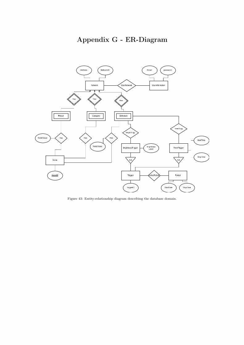
Appendix G - ER-Diagram
Figure 43: Entity-relationship diagram describing the database domain.

Appendix H - Dimmer Adapter Schematic
Figure 44: The schematic of the dimmer adapter.