Embed Size (px)
Citation preview
GeoVision 1 Date: 5/30/2019
GV-Eye Mobile App.
1. Specifications .......................................................................................................................... 2
2. Supported GV-IP Devices and Software................................................................................ 3
2.1 Supported Products for Connection ................................................................................ 3
2.2 Supported Products for Enabling Monitoring................................................................... 5
2.3 Supported Products for Assigning NAS Storage Path..................................................... 5
3. Installing GV-Eye ..................................................................................................................... 6
4. Main Page ................................................................................................................................. 7
5. GV-Relay QR Code .................................................................................................................. 9
5.1 Setting up GV-Relay Account ........................................................................................ 10
5.2 Managing GV-Relay Account .........................................................................................11
5.2.1 Purchasing Relay Data .......................................................................................... 12
5.2.2 Sharing Relay Data ................................................................................................ 13
5.3 Connecting via GV-Relay QR Code .............................................................................. 14
6. Manual & Automatic Connection for GV-IP Devices and Software .................................. 17
6.1 Required Configurations on GV-Software before Connecting....................................... 18
6.1.1 Connection Settings on GV-VMS........................................................................... 19
6.1.2 Connection Settings on GV-DVR / NVR ................................................................ 20
6.1.3 Connection Settings on GV-Recording Server / Video Gateway........................... 21
6.2 Configuring Windows Firewall for Communication........................................................ 22
6.3 Port Forwarding ............................................................................................................. 24
6.4 Manual Connection........................................................................................................ 25
6.5 Automatic Connection ................................................................................................... 27
7. Group Management ............................................................................................................... 30
8. Live View ................................................................................................................................ 32
9. Playing Back Recordings ..................................................................................................... 37
9.1 Accessing the Recorded Files ....................................................................................... 37
9.2 Playback Display ........................................................................................................... 39
10. Edge Settings....................................................................................................................... 42
10.1 Changing IP Address................................................................................................... 43
10.2 Changing Device Name............................................................................................... 44
10.3 Assigning Storage Path ............................................................................................... 45
10.4 Monitoring HDD Storage.............................................................................................. 47
11. System Settings ................................................................................................................... 48
12. Defining the User Privilege of GV-VMS for GV-Eye.......................................................... 50

GeoVision 2 Date: 5/30/2019
GV-Eye
Using GV-Eye, you can access and monitor GV-IP devices and software remotely, to watch
multiple live views, play back recordings, trigger remote outputs and take snapshots from your
mobile device.
IMPORTANT: Starting from GV-Eye V2.7, users can connect to GV-VMS (18.1), GV-DVR/NVR
(8.8.0) and GV-Recording Server/Video Gateway (V2.0.0) via GV-Relay QR-code. This is a paid
service that results in connecting to GV-SNVR via QR-code scan to be charged as well.
1. Specifications
General
Supported OS iOS 8 ~ 12.1; Android 5.0 or later
Codec MPEG4, MJPEG, H.264 and H.265
Resolutions Up to 12 MP (4000 x 3000)
Functions
360° Mode, Live View, PIP (Picture-in-picture), Fisheye
Dewarping, PTZ Control & Preset, Remote Playback, I/O
Output trigger, Snapshot, 2-Way Audio, Stream Switching,
Device Search, Hardware Decoding, Add via QR code
Default Port Settings
Below is a list of default port for GeoVision services that are used for remote connection.
Service Connection Port Playback Port
GV-IP devices
(VSS Port) 10000
5552
80
GV-Recording Server / Video
Gateway Server 11000 5552
GV-Mobile Server 55000 N/A
GV-VMS 56000 5552
GV-DVR/NVR 56000 5552
GV-SNVR 10000 80
GeoVision 3 Date: 5/30/2019
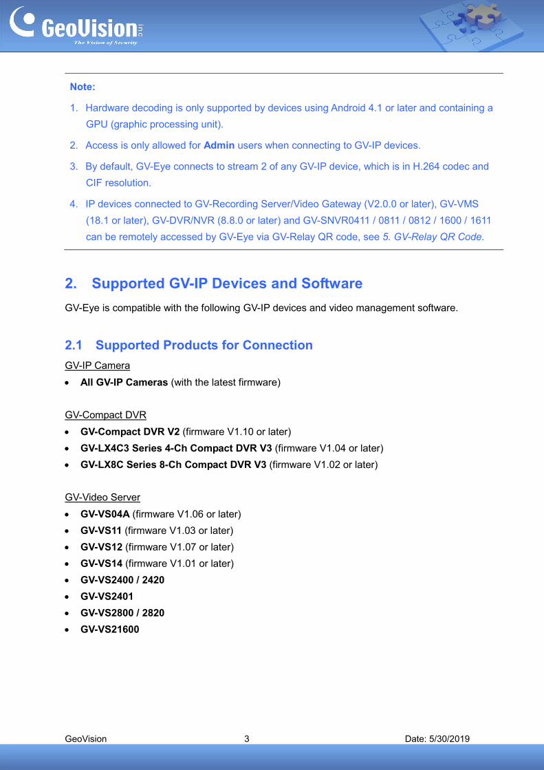
Note:
1. Hardware decoding is only supported by devices using Android 4.1 or later and containing a
GPU (graphic processing unit).
2. Access is only allowed for Admin users when connecting to GV-IP devices.
3. By default, GV-Eye connects to stream 2 of any GV-IP device, which is in H.264 codec and
CIF resolution.
4. IP devices connected to GV-Recording Server/Video Gateway (V2.0.0 or later), GV-VMS
(18.1 or later), GV-DVR/NVR (8.8.0 or later) and GV-SNVR0411 / 0811 / 0812 / 1600 / 1611
can be remotely accessed by GV-Eye via GV-Relay QR code, see 5. GV-Relay QR Code.
2. Supported GV-IP Devices and Software
GV-Eye is compatible with the following GV-IP devices and video management software.
2.1 Supported Products for Connection
GV-IP Camera
All GV-IP Cameras (with the latest firmware)
GV-Compact DVR
GV-Compact DVR V2 (firmware V1.10 or later)
GV-LX4C3 Series 4-Ch Compact DVR V3 (firmware V1.04 or later)
GV-LX8C Series 8-Ch Compact DVR V3 (firmware V1.02 or later)
GV-Video Server
GV-VS04A (firmware V1.06 or later)
GV-VS11 (firmware V1.03 or later)
GV-VS12 (firmware V1.07 or later)
GV-VS14 (firmware V1.01 or later)
GV-VS2400 / 2420
GV-VS2401
GV-VS2800 / 2820
GV-VS21600
GeoVision 4 Date: 5/30/2019
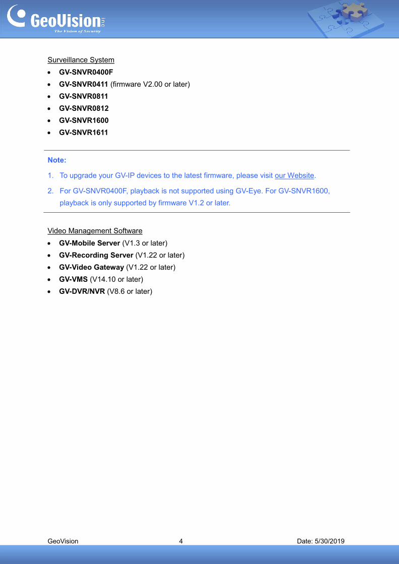
Surveillance System
GV-SNVR0400F
GV-SNVR0411 (firmware V2.00 or later)
GV-SNVR0811
GV-SNVR0812
GV-SNVR1600
GV-SNVR1611
Note:
1. To upgrade your GV-IP devices to the latest firmware, please visit our Website.
2. For GV-SNVR0400F, playback is not supported using GV-Eye. For GV-SNVR1600,
playback is only supported by firmware V1.2 or later.
Video Management Software
GV-Mobile Server (V1.3 or later)
GV-Recording Server (V1.22 or later)
GV-Video Gateway (V1.22 or later)
GV-VMS (V14.10 or later)
GV-DVR/NVR (V8.6 or later)

GeoVision 5 Date: 5/30/2019
2.2 Supported Products for Enabling Monitoring
GV-Eye can only enable or disable monitoring of the following supported products and
versions.
GV-IP Camera
All GV-IP Cameras (with the latest firmware)
GV-Video Server
GV-VS11 (firmware V1.03 or later)
GV-VS12 (firmware V1.07 or later)
GV-VS14 (firmware V1.01 or later)
GV-VS2400 / 2420
GV-VS2401
GV-VS2800 / 2820
GV-VS21600
Video Management Software
GV-VMS (V15.10 or later)
2.3 Supported Products for Assigning NAS Storage Path
GV-Eye can only assign NAS storage path for the following supported products and versions.
GV-IP Camera
GV-Target IP Cameras (firmware V1.02 or later)
Other GV-IP Cameras (firmware V3.0 or later)
GeoVision 6 Date: 5/30/2019
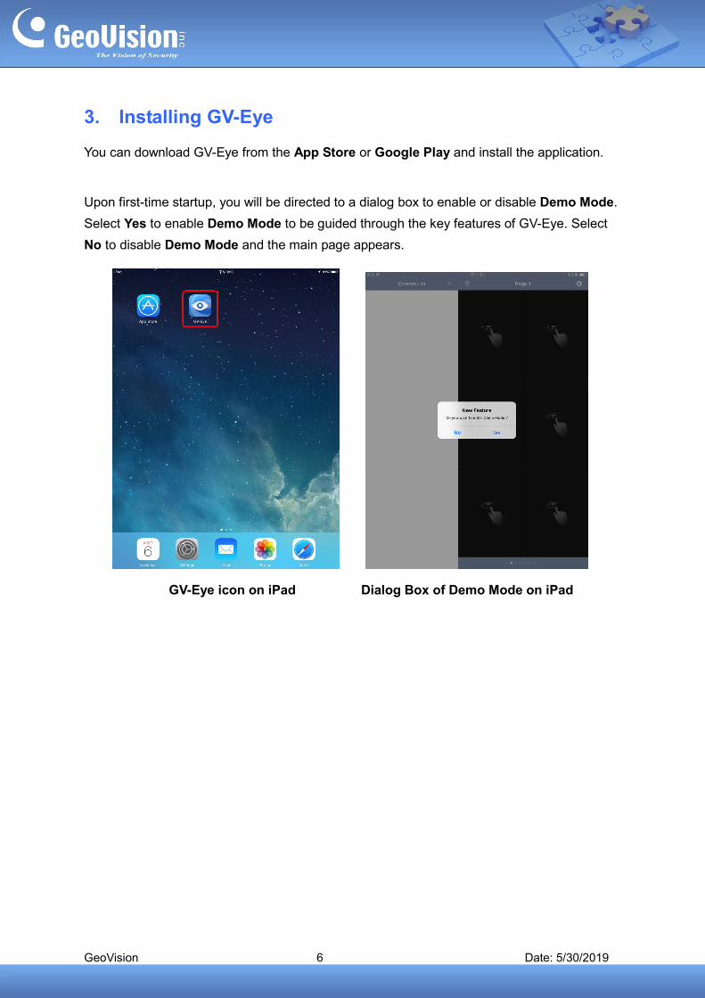
3. Installing GV-Eye
You can download GV-Eye from the App Store or Google Play and install the application.
Upon first-time startup, you will be directed to a dialog box to enable or disable Demo Mode.
Select Yes to enable Demo Mode to be guided through the key features of GV-Eye. Select
No to disable Demo Mode and the main page appears.
GV-Eye icon on iPad Dialog Box of Demo Mode on iPad
GeoVision 7 Date: 5/30/2019
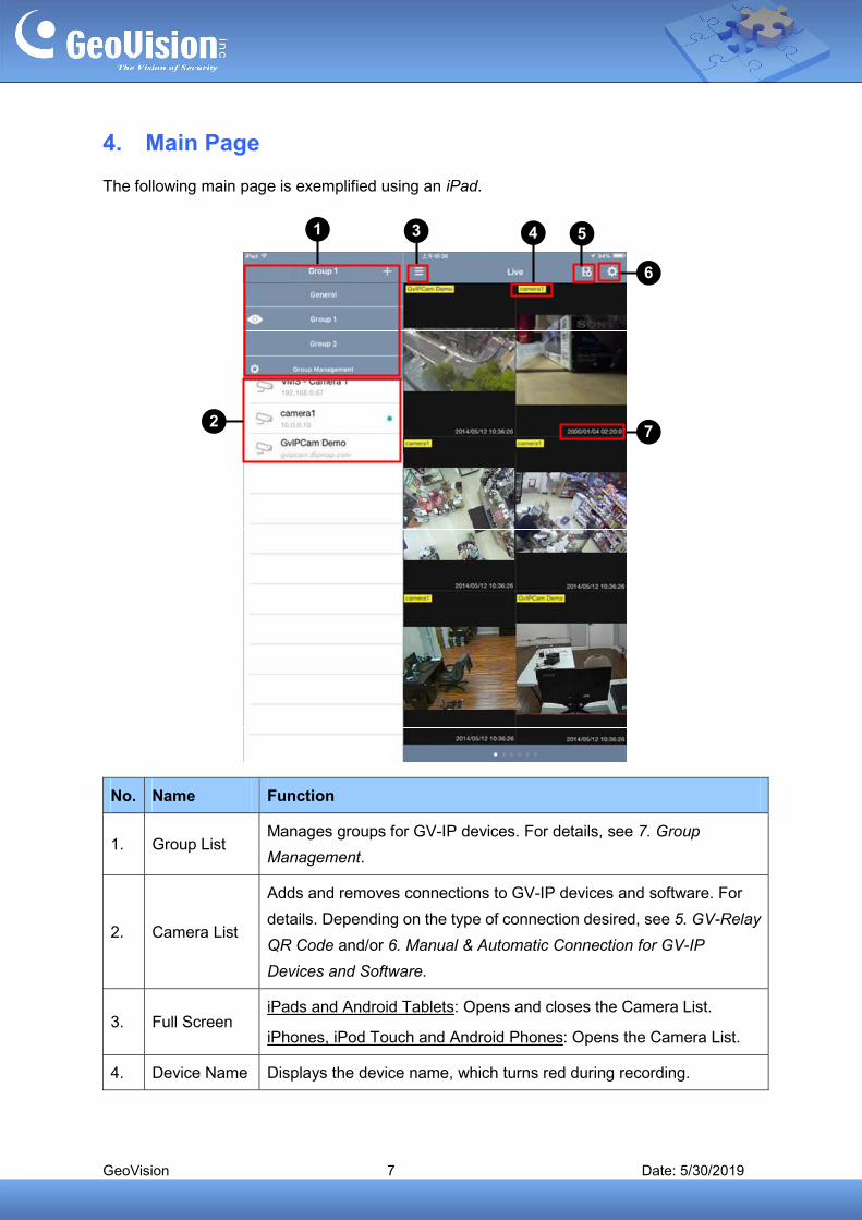
4. Main Page
The following main page is exemplified using an iPad.
1 4
6
7
3 5
2
No. Name Function
1. Group List Manages groups for GV-IP devices. For details, see 7. Group
Management.
2. Camera List
Adds and removes connections to GV-IP devices and software. For
details. Depending on the type of connection desired, see 5. GV-Relay
QR Code and/or 6. Manual & Automatic Connection for GV-IP
Devices and Software.
3. Full Screen iPads and Android Tablets: Opens and closes the Camera List.
iPhones, iPod Touch and Android Phones: Opens the Camera List.
4. Device Name Displays the device name, which turns red during recording.
GeoVision 8 Date: 5/30/2019
No. Name Function
5. Edge Setting Configures IP address and recording storage path of the device.
6. Settings Tap this button to access the GV-Eye settings. For details, see
11. System Settings.
7. Device Time Displays the device time.
GeoVision 9 Date: 5/30/2019
5. GV-Relay QR Code
GV-Eye can be connected to GV-IP devices and software under the same LAN, through the
Internet or by scanning of the GV-Relay QR code. The following sections focus on connecting
by GV-Relay QR-code, which avoids the precondition of configuring for Windows Firewall and
port forwarding. To do this, the binding of a GV-Relay account is required, see 5.1 Setting up
GV-Relay Account.
Note:
1. This function is only supported by GV-DVR/NVR (V8.8.0 or later), GV-VMS (18.1 or
later), GV-Recording Server/Video Gateway (V2.0.0 or later), GV-SNVR0411 (firmware
V2.00 or later), GV-SNVR0811 (firmware V2.30 or later), GV-SNVR1600 (firmware
V1.20 or later), GV-SNVR0812 and GV-SNVR1611.
2. All images streamed via GV-Relay QR-code connection shall consume the data within
the GV-Relay account according to their resolutions and fps, and you won’t be able to
access such streams once the data is used up.
3. The GV-Relay data is a paid service and if users don’t want to purchase data after the
free quota given is used up, they may connect manually, see 6. Manual & Automatic
Connection for GV-IP Devices and Software.
4. To use this function, the GV-Software must be connected to the Internet.
5. To connect manually or detect for GV-IP devices under the same LAN, see 6 Manual &
Automatic Connection for GV-IP Devices and Software.
GeoVision 10 Date: 5/30/2019
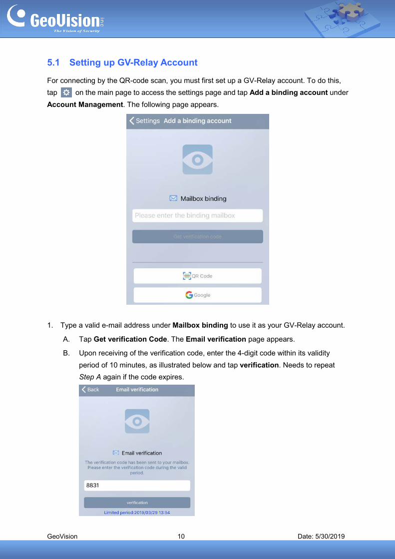
5.1 Setting up GV-Relay Account
For connecting by the QR-code scan, you must first set up a GV-Relay account. To do this,
tap on the main page to access the settings page and tap Add a binding account under
Account Management. The following page appears.
1. Type a valid e-mail address under Mailbox binding to use it as your GV-Relay account.
A. Tap Get verification Code. The Email verification page appears.
B. Upon receiving of the verification code, enter the 4-digit code within its validity
period of 10 minutes, as illustrated below and tap verification. Needs to repeat
Step A again if the code expires.
GeoVision 11 Date: 5/30/2019
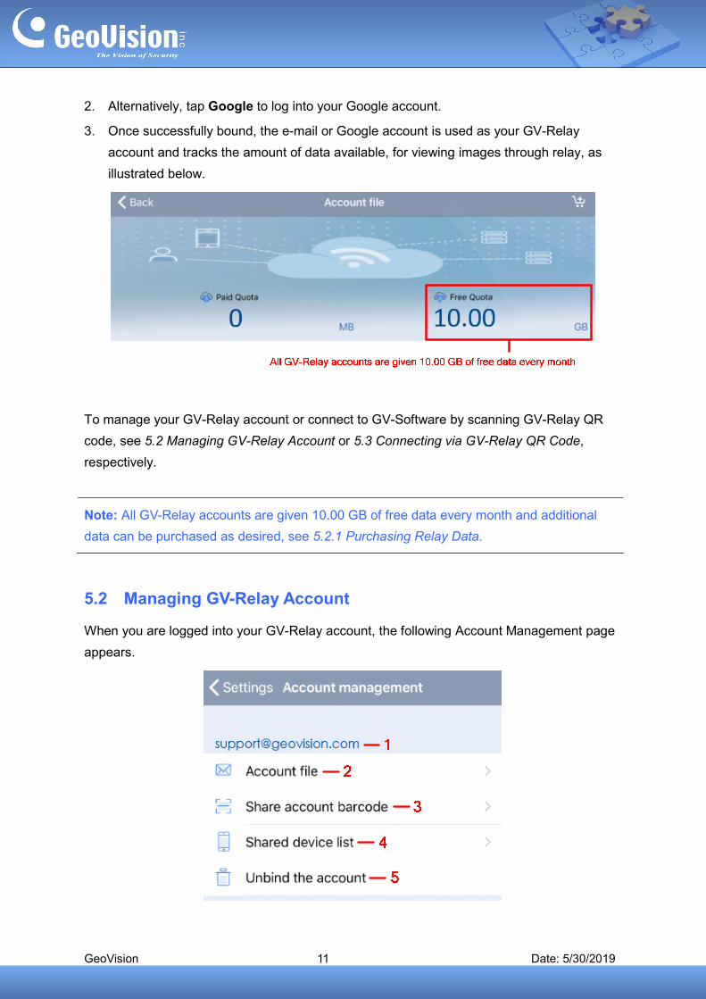
2. Alternatively, tap Google to log into your Google account.
3. Once successfully bound, the e-mail or Google account is used as your GV-Relay
account and tracks the amount of data available, for viewing images through relay, as
illustrated below.
To manage your GV-Relay account or connect to GV-Software by scanning GV-Relay QR
code, see 5.2 Managing GV-Relay Account or 5.3 Connecting via GV-Relay QR Code,
respectively.
Note: All GV-Relay accounts are given 10.00 GB of free data every month and additional
data can be purchased as desired, see 5.2.1 Purchasing Relay Data.
5.2 Managing GV-Relay Account
When you are logged into your GV-Relay account, the following Account Management page
appears.

GeoVision 12 Date: 5/30/2019
No. Name Function
1. Account name Displays the GV-Relay account currently logged in.
2. Account file Tap to view the amount of data on the GV-Relay account and/or
purchase data. See 5.2.1 Purchasing Relay Data.
3. Share account
barcode
Tap to display a QR code for sharing the account’s data to other
mobile devices. See 5.2.2 Sharing Relay Data.
4. Shared device list Tap to display all mobile device(s) using the data of the
GV-Relay account logged in. See 5.2.2 Sharing Relay Data.
5. Unbind the account Tap to log off the GV-Relay account.
5.2.1 Purchasing Relay Data
To purchase data, tap Account file (No. 2, 5.2 Managing GV-Relay Account) and Shopping
cart . The Purchase page appears.
Tap the Shopping cart next to the amount of data you want to purchase.
GeoVision 13 Date: 5/30/2019
5.2.2 Sharing Relay Data
The data of a GV-Relay account can be shared to other mobile devices for GV-Relay
streaming on those devices. To share the data from device A to device B, follow the steps
below:
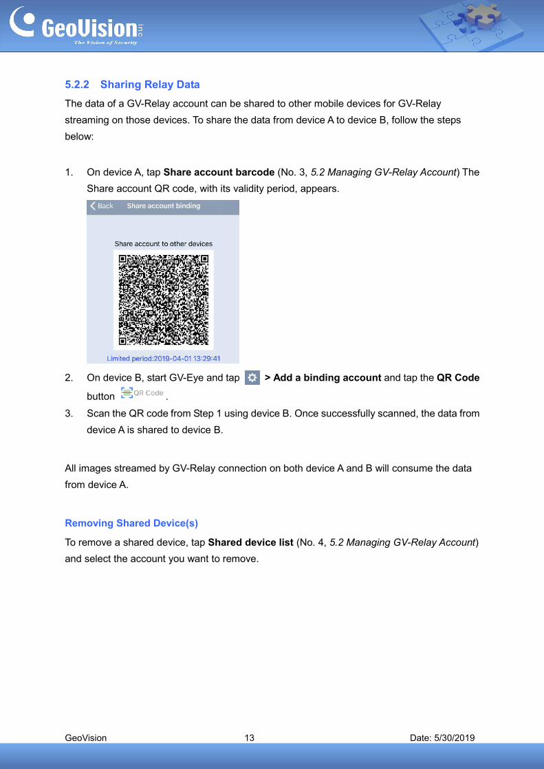
1. On device A, tap Share account barcode (No. 3, 5.2 Managing GV-Relay Account) The
Share account QR code, with its validity period, appears.
2. On device B, start GV-Eye and tap > Add a binding account and tap the QR Code
button .
3. Scan the QR code from Step 1 using device B. Once successfully scanned, the data from
device A is shared to device B.
All images streamed by GV-Relay connection on both device A and B will consume the data
from device A.
Removing Shared Device(s)
To remove a shared device, tap Shared device list (No. 4, 5.2 Managing GV-Relay Account)
and select the account you want to remove.
GeoVision 14 Date: 5/30/2019
5.3 Connecting via GV-Relay QR Code
You can connect to GV-Software by scanning its GV-Relay QR code. To do this, follow the
steps below.
Note:
1. For connecting by the QR-code scan, you must first set up a GV-Relay account, see
5.1 Setting up GV-Relay Account.
2. To use this function, the GV-Software must be connected to the Internet.
3. For the list of GV-Software supported, refer to Note 1 in 5. GV-Relay QR Code
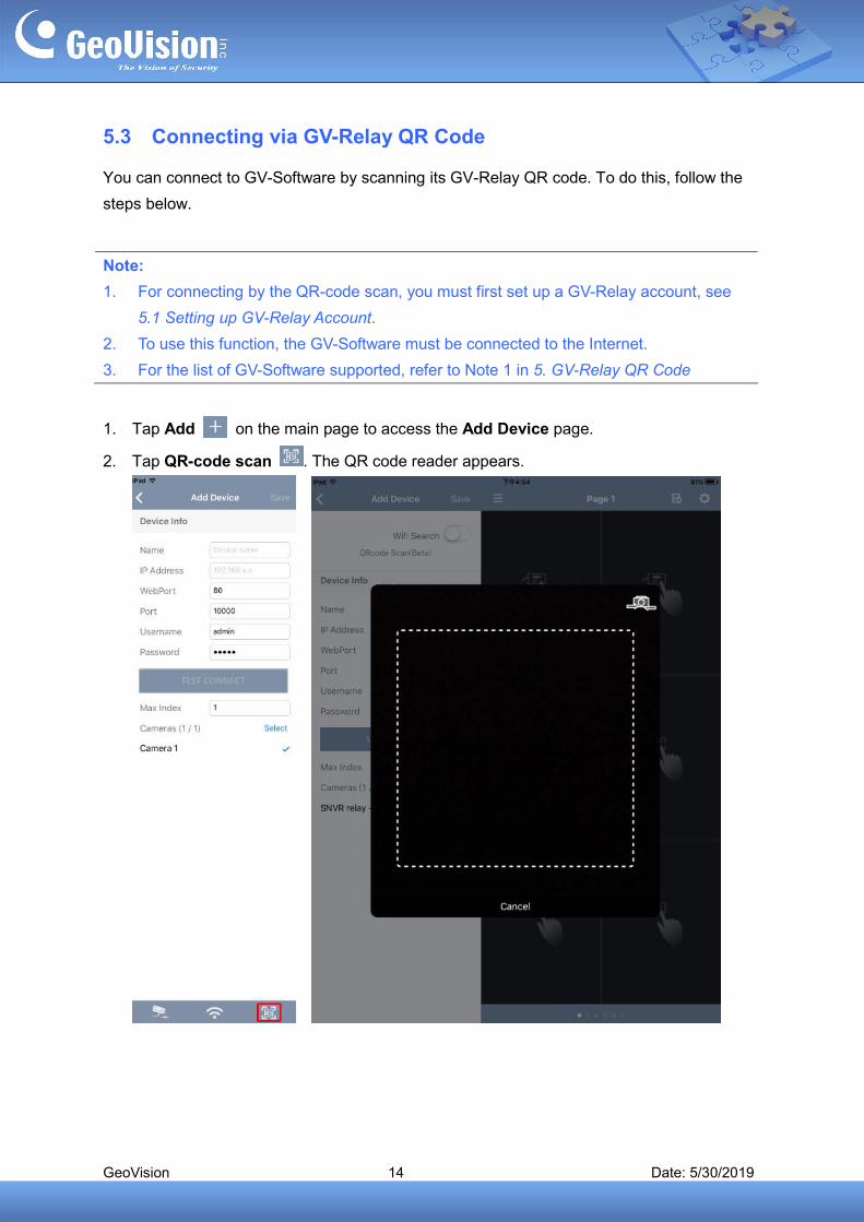
1. Tap Add on the main page to access the Add Device page.
2. Tap QR-code scan . The QR code reader appears.

GeoVision 15 Date: 5/30/2019
3. On the GV-Software, go to its corresponding service/settings page, as described below:
A. For GV-VMS, click Toolbar > Network > Mobile Server > QR Code, select Enable
and click Start. Once enabled, close the dialog box and scan the QR code within
WebCam, which can be accessed via Windows notification.
B. For GV-DVR/NVR, click Network > Webcam Server > QR Code, select Enable
and click OK for the changes to take effect. Note that the Mobile Server (Webcam
Server > Mobile) must be enabled first. Once enabled, close the dialog box and
scan the QR code within WebCam, which can be accessed via Windows
notification.
GeoVision 16 Date: 5/30/2019
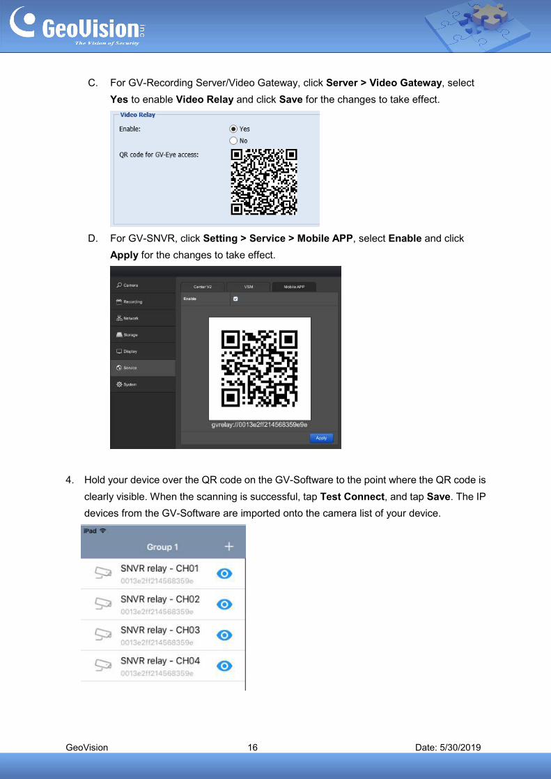
C. For GV-Recording Server/Video Gateway, click Server > Video Gateway, select
Yes to enable Video Relay and click Save for the changes to take effect.
D. For GV-SNVR, click Setting > Service > Mobile APP, select Enable and click
Apply for the changes to take effect.
4. Hold your device over the QR code on the GV-Software to the point where the QR code is
clearly visible. When the scanning is successful, tap Test Connect, and tap Save. The IP
devices from the GV-Software are imported onto the camera list of your device.
GeoVision 17 Date: 5/30/2019
6. Manual & Automatic Connection for GV-IP Devices and
Software
GV-Eye can be connected to GV-IP devices and software under the same LAN or through the
Internet.
Note:
1. To connect by the GV-Relay QR code, see 5. GV-Relay QR Code.
2. If the GV-IP Devices and/or software to which you want to connect isn’t behind a
Windows Firewall or router, the related settings may be skipped.
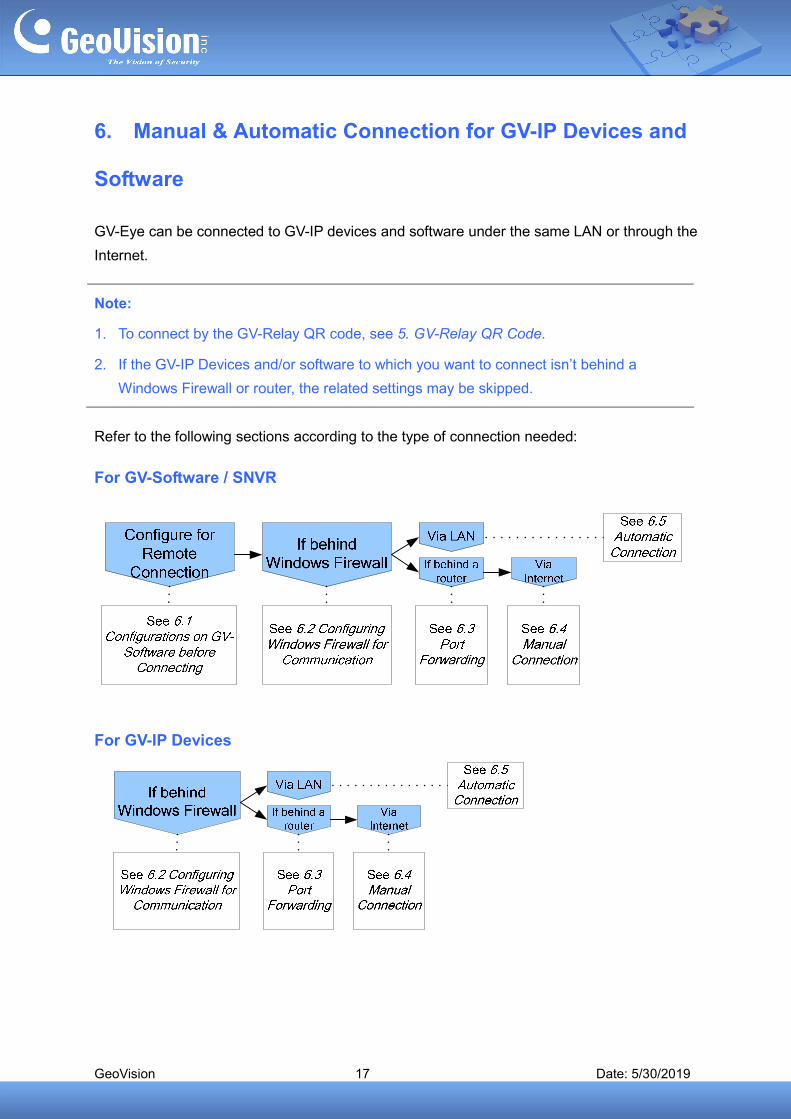
Refer to the following sections according to the type of connection needed:
For GV-Software / SNVR
For GV-IP Devices
GeoVision 18 Date: 5/30/2019
6.1 Required Configurations on GV-Software before Connecting
For GV-Software to be accessible by GV-Eye, the related services and the corresponding
port(s) must first be enabled. Refer to the following sections depending on the type of
GV-Software in which you want to connect:
For GV-VMS, see 6.1.1 Connection Settings on GV-VMS
For GV-DVR / NVR, see 6.1.2 Connection Settings on GV-DVR / NVR
For GV-Recording Server / Video Gateway, see 6.1.3 Connection Settings on
GV-Recording Server / Video Gateway
Note:
1. There are no required configurations for GV-SNVR to be accessible by GV-Eye. If the
GV-SNVR is behind a router, see 6.3 Port Forwarding and 6.4 Manual Connection,
respectively, for connecting to GV-Eye through the Internet. Otherwise see 6.5 Automatic
Connection for connecting to GV-Eye within the same LAN.
2. While there are also no required configurations for GV-Mobile Server, if it is behind an
active Windows Firewall, make sure its mobile service is allowed for communication. See
6.2 Configuring Windows Firewall for Communication.

GeoVision 19 Date: 5/30/2019
6.1.1 Connection Settings on GV-VMS
1. On your GV-VMS, click Home > Toolbar > Network > Mobile Service.
The Mobile Server Lite dialog box appears.
2. Keep the default Server Port of 56000 or modify if necessary and click Start.
3. Click Home > Toolbar > Network to make sure Mobile Service is
enabled, and optionally click Control Center Server and enable Remote ViewLog
Service to allow remote playback through GV-Eye.
IMPORTANT: After the abovementioned settings are set, if the PC has an active Windows
Firewall, the related services must also be enabled on the Windows Firewall for GV-VMS to
be accessible by GV-Eye. See 6.2 Configuring Windows Firewall for Communication.
GeoVision 20 Date: 5/30/2019
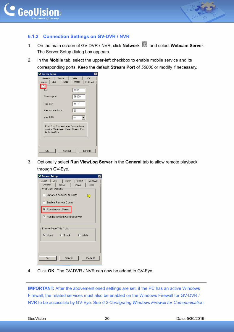
6.1.2 Connection Settings on GV-DVR / NVR
1. On the main screen of GV-DVR / NVR, click Network and select Webcam Server.
The Server Setup dialog box appears.
2. In the Mobile tab, select the upper-left checkbox to enable mobile service and its
corresponding ports. Keep the default Stream Port of 56000 or modify if necessary.
3. Optionally select Run ViewLog Server in the General tab to allow remote playback
through GV-Eye.
4. Click OK. The GV-DVR / NVR can now be added to GV-Eye.
IMPORTANT: After the abovementioned settings are set, if the PC has an active Windows
Firewall, the related services must also be enabled on the Windows Firewall for GV-DVR /
NVR to be accessible by GV-Eye. See 6.2 Configuring Windows Firewall for Communication.
GeoVision 21 Date: 5/30/2019
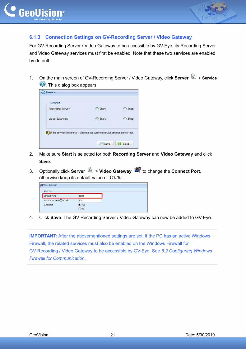
6.1.3 Connection Settings on GV-Recording Server / Video Gateway
For GV-Recording Server / Video Gateway to be accessible by GV-Eye, its Recording Server
and Video Gateway services must first be enabled. Note that these two services are enabled
by default.
1. On the main screen of GV-Recording Server / Video Gateway, click Server > Service
. This dialog box appears.
2. Make sure Start is selected for both Recording Server and Video Gateway and click
Save.
3. Optionally click Server > Video Gateway to change the Connect Port,
otherwise keep its default value of 11000.
4. Click Save. The GV-Recording Server / Video Gateway can now be added to GV-Eye.
IMPORTANT: After the abovementioned settings are set, if the PC has an active Windows
Firewall, the related services must also be enabled on the Windows Firewall for
GV-Recording / Video Gateway to be accessible by GV-Eye. See 6.2 Configuring Windows
Firewall for Communication.
GeoVision 22 Date: 5/30/2019
6.2 Configuring Windows Firewall for Communication
For GV-Software installed on a PC with active Windows Firewall to be accessible by GV-Eye,
the related services/programs must first be enabled:
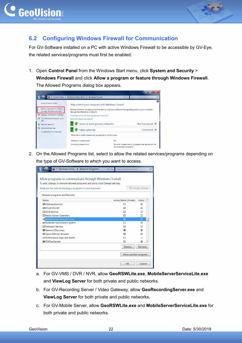
1. Open Control Panel from the Windows Start menu, click System and Security >
Windows Firewall and click Allow a program or feature through Windows Firewall.
The Allowed Programs dialog box appears.
2. On the Allowed Programs list, select to allow the related services/programs depending on
the type of GV-Software to which you want to access.
a. For GV-VMS / DVR / NVR, allow GeoRSWLite.exe, MobileServerServiceLite.exe
and ViewLog Server for both private and public networks.
b. For GV-Recording Server / Video Gateway, allow GeoRecordingServer.exe and
ViewLog Server for both private and public networks.
c. For GV-Mobile Server, allow GeoRSWLite.exe and MobileServerServiceLite.exe for
both private and public networks.
GeoVision 23 Date: 5/30/2019
3. Click OK. The GV-Software can now be communicated through Windows Firewall.
Note:
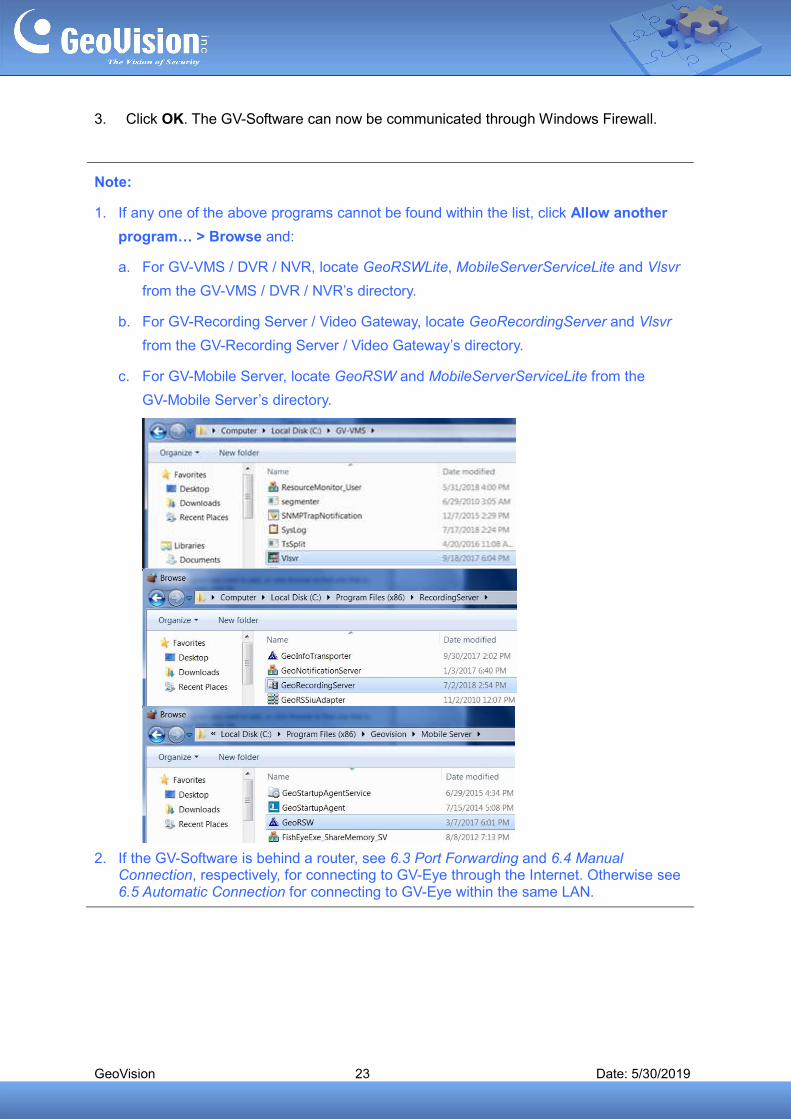
1. If any one of the above programs cannot be found within the list, click Allow another
program… > Browse and:
a. For GV-VMS / DVR / NVR, locate GeoRSWLite, MobileServerServiceLite and Vlsvr
from the GV-VMS / DVR / NVR’s directory.
b. For GV-Recording Server / Video Gateway, locate GeoRecordingServer and Vlsvr
from the GV-Recording Server / Video Gateway’s directory.
c. For GV-Mobile Server, locate GeoRSW and MobileServerServiceLite from the
GV-Mobile Server’s directory.
2. If the GV-Software is behind a router, see 6.3 Port Forwarding and 6.4 Manual Connection, respectively, for connecting to GV-Eye through the Internet. Otherwise see 6.5 Automatic Connection for connecting to GV-Eye within the same LAN.
GeoVision 24 Date: 5/30/2019
6.3 Port Forwarding
If the GV-IP devices and/or software to which you are trying to connect are behind a router,
you need to configure for port forwarding.
IMPORTANT: Prior to port forwarding, first make sure you have a public IP accessible
through the Internet. This can be done by one of the following:
1. Register for a static public IP address from your Internet Service Provider (ISP).
2. Assign a domain name to your dynamic public IP address through the router’s DDNS
settings. Consult your router manufacturer for details.
1. For port forwarding depending on the brand and model of your router, click here.
2. Make sure the ports mapped coincide with the GV-IP devices and software to which you
want to connect:
Default Connection Port Default Playback Port
GV-IP devices (VSS Port)
10000 5552 80
GV-Recording Server / Video Gateway Server
11000 5552
GV-Mobile Server 55000 N/A
GV-VMS 56000 5552
GV-DVR/NVR 56000 5552
GV-SNVR 10000 80
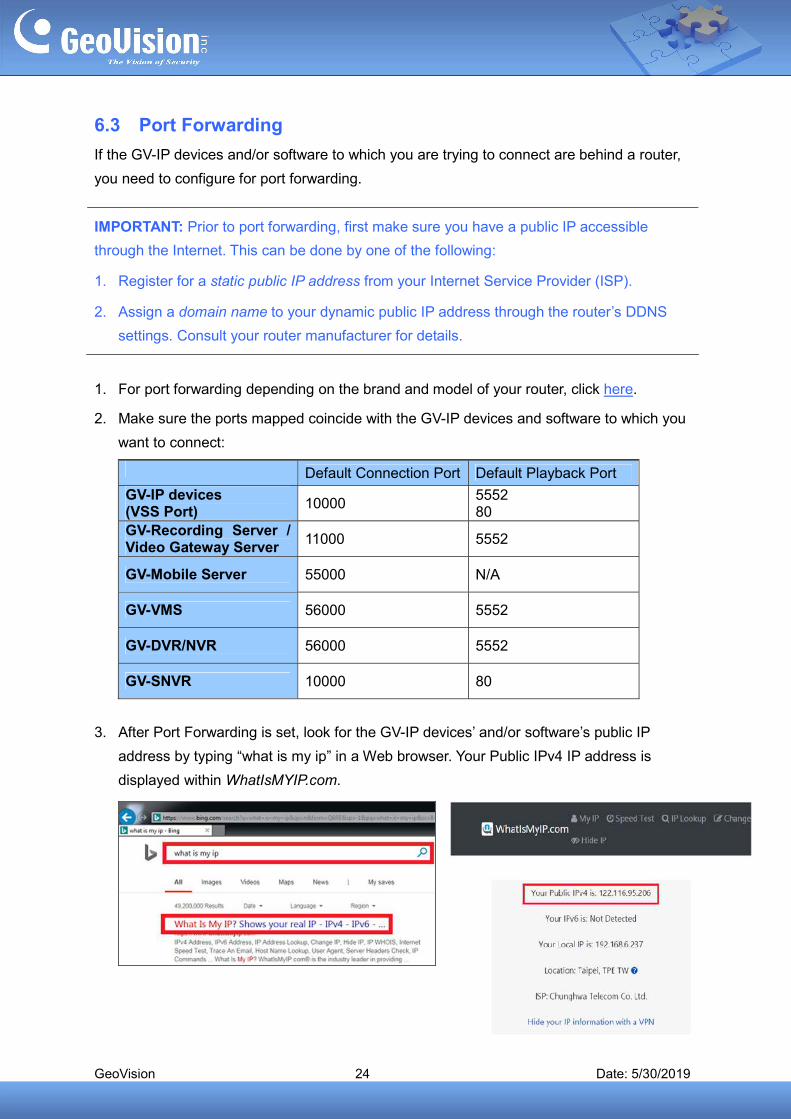
3. After Port Forwarding is set, look for the GV-IP devices’ and/or software’s public IP
address by typing “what is my ip” in a Web browser. Your Public IPv4 IP address is
displayed within WhatIsMYIP.com.
GeoVision 25 Date: 5/30/2019
6.4 Manual Connection
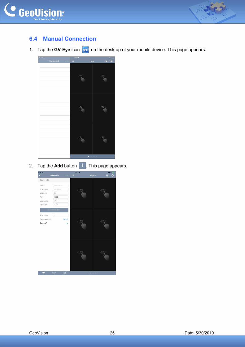
1. Tap the GV-Eye icon on the desktop of your mobile device. This page appears.
2. Tap the Add button . This page appears.
GeoVision 26 Date: 5/30/2019
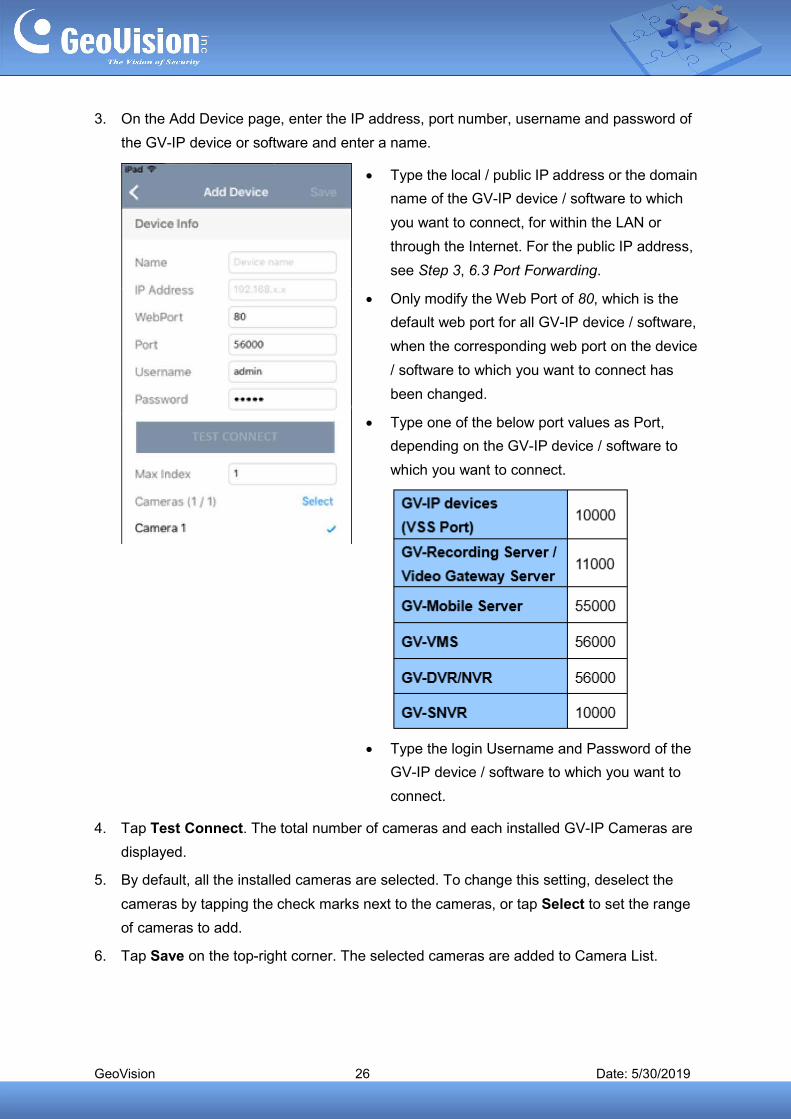
3. On the Add Device page, enter the IP address, port number, username and password of
the GV-IP device or software and enter a name.
Type the local / public IP address or the domain
name of the GV-IP device / software to which
you want to connect, for within the LAN or
through the Internet. For the public IP address,
see Step 3, 6.3 Port Forwarding.
Only modify the Web Port of 80, which is the
default web port for all GV-IP device / software,
when the corresponding web port on the device
/ software to which you want to connect has
been changed.
Type one of the below port values as Port,
depending on the GV-IP device / software to
which you want to connect.
Type the login Username and Password of the
GV-IP device / software to which you want to
connect.
4. Tap Test Connect. The total number of cameras and each installed GV-IP Cameras are
displayed.
5. By default, all the installed cameras are selected. To change this setting, deselect the
cameras by tapping the check marks next to the cameras, or tap Select to set the range
of cameras to add.
6. Tap Save on the top-right corner. The selected cameras are added to Camera List.
GeoVision 27 Date: 5/30/2019
6.5 Automatic Connection
For automatic connection, GV-IP devices and software must be within the same LAN as your
GV-Eye. For connecting to GV-Software, the related settings on the respective software must
first be configured, see 6.1 Required Configurations on GV-Software before Connecting.
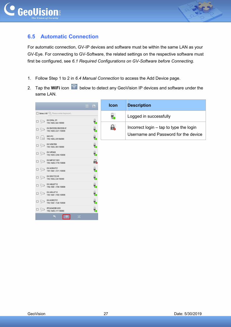
1. Follow Step 1 to 2 in 6.4 Manual Connection to access the Add Device page.
2. Tap the WiFi icon below to detect any GeoVision IP devices and software under the
same LAN.
Icon Description
Logged in successfully
Incorrect login – tap to type the login
Username and Password for the device
GeoVision 28 Date: 5/30/2019
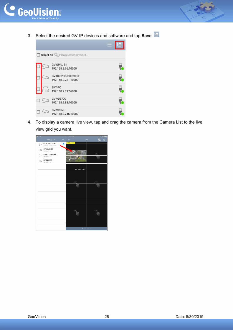
3. Select the desired GV-IP devices and software and tap Save .
4. To display a camera live view, tap and drag the camera from the Camera List to the live
view grid you want.
GeoVision 29 Date: 5/30/2019
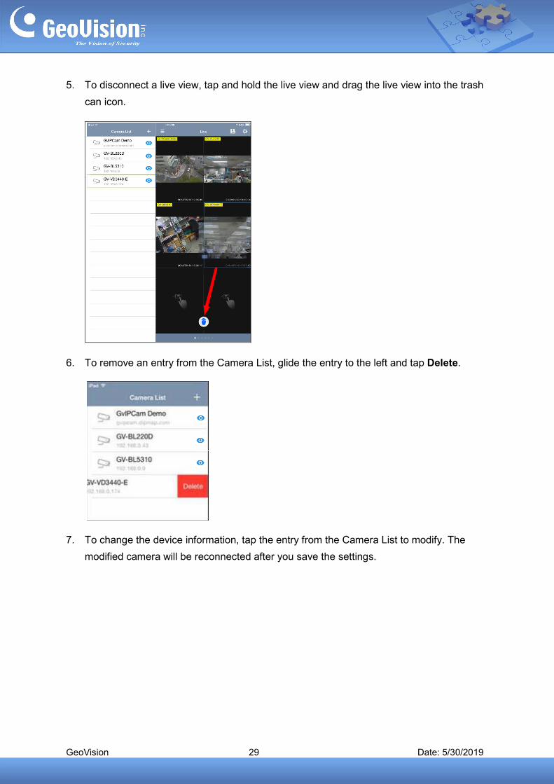
5. To disconnect a live view, tap and hold the live view and drag the live view into the trash
can icon.
6. To remove an entry from the Camera List, glide the entry to the left and tap Delete.
7. To change the device information, tap the entry from the Camera List to modify. The
modified camera will be reconnected after you save the settings.
GeoVision 30 Date: 5/30/2019
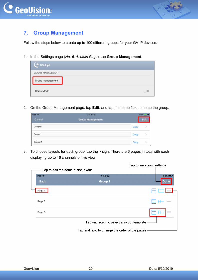
7. Group Management
Follow the steps below to create up to 100 different groups for your GV-IP devices.
1. In the Settings page (No. 6, 4. Main Page), tap Group Management.
2. On the Group Management page, tap Edit, and tap the name field to name the group.
3. To choose layouts for each group, tap the > sign. There are 6 pages in total with each
displaying up to 16 channels of live view.

GeoVision 31 Date: 5/30/2019
4. Return to the main page and select a desired group for adding IP devices.
Click to display the drop-down
list of the group menu
GeoVision 32 Date: 5/30/2019
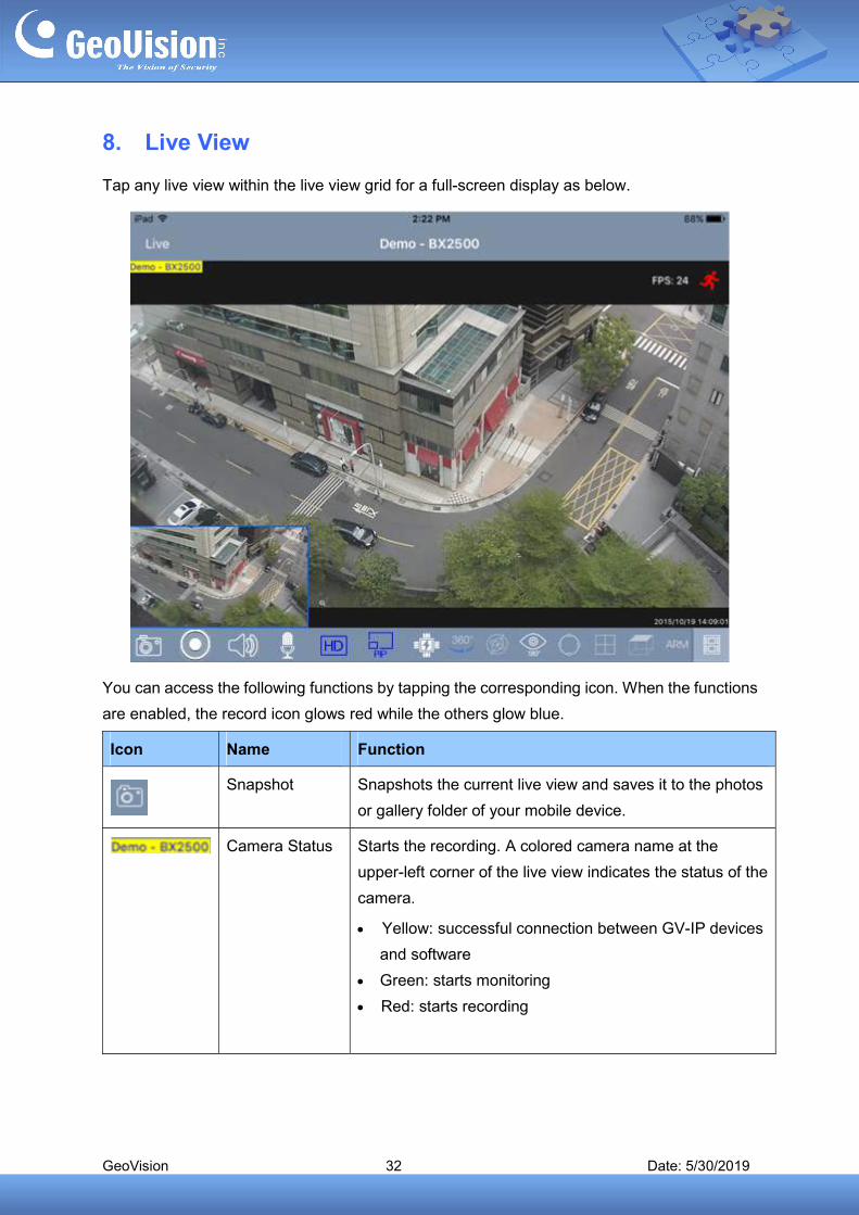
8. Live View
Tap any live view within the live view grid for a full-screen display as below.
You can access the following functions by tapping the corresponding icon. When the functions
are enabled, the record icon glows red while the others glow blue.
Icon Name Function
Snapshot Snapshots the current live view and saves it to the photos
or gallery folder of your mobile device.
Camera Status Starts the recording. A colored camera name at the
upper-left corner of the live view indicates the status of the
camera.
Yellow: successful connection between GV-IP devices
and software
Green: starts monitoring
Red: starts recording
GeoVision 33 Date: 5/30/2019
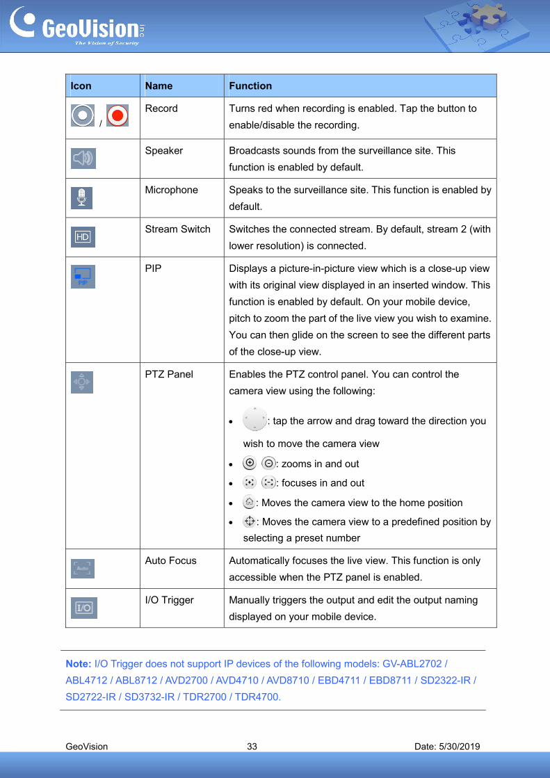
Icon Name Function
/
Record
Turns red when recording is enabled. Tap the button to
enable/disable the recording.
Speaker Broadcasts sounds from the surveillance site. This
function is enabled by default.
Microphone Speaks to the surveillance site. This function is enabled by
default.
Stream Switch Switches the connected stream. By default, stream 2 (with
lower resolution) is connected.
PIP Displays a picture-in-picture view which is a close-up view
with its original view displayed in an inserted window. This
function is enabled by default. On your mobile device,
pitch to zoom the part of the live view you wish to examine.
You can then glide on the screen to see the different parts
of the close-up view.
PTZ Panel Enables the PTZ control panel. You can control the
camera view using the following:
: tap the arrow and drag toward the direction you
wish to move the camera view
: zooms in and out
: focuses in and out
: Moves the camera view to the home position
: Moves the camera view to a predefined position by
selecting a preset number
Auto Focus Automatically focuses the live view. This function is only
accessible when the PTZ panel is enabled.
I/O Trigger Manually triggers the output and edit the output naming
displayed on your mobile device.
Note: I/O Trigger does not support IP devices of the following models: GV-ABL2702 /
ABL4712 / ABL8712 / AVD2700 / AVD4710 / AVD8710 / EBD4711 / EBD8711 / SD2322-IR /
SD2722-IR / SD3732-IR / TDR2700 / TDR4700.
GeoVision 34 Date: 5/30/2019
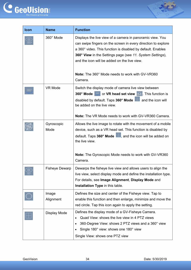
Icon Name Function
360° Mode Displays the live view of a camera in panoramic view. You
can swipe fingers on the screen in every direction to explore
a 360° video. This function is disabled by default. Enables
360° View in the Settings page (see 11. System Settings),
and the icon will be added on the live view.
Note: The 360° Mode needs to work with GV-VR360
Camera.
VR Mode Switch the display mode of camera live view between
360° Mode or VR head set view . This function is
disabled by default. Taps 360° Mode and the icon will
be added on the live view.
Note: The VR Mode needs to work with GV-VR360 Camera.
Gyroscopic
Mode
Allows the live image to rotate with the movement of a mobile
device, such as a VR head set. This function is disabled by
default. Taps 360° Mode , and the icon will be added on
the live view.
Note: The Gyroscopic Mode needs to work with GV-VR360
Camera.
Fisheye Dewarp
Dewarps the fisheye live view and allows users to align the
live view, select display mode and define the installation type.
For details, see Image Alignment, Display Mode and
Installation Type in this table.
Image
Alignment
Defines the size and center of the Fisheye view. Tap to
enable this function and then enlarge, minimize and move the
red circle. Tap this icon again to apply the setting.
Display Mode Defines the display mode of a GV-Fisheye Camera.
Quad View: shows the live view in 4 PTZ views
360-Degree View: shows 2 PTZ views and a 360° view
Single 180° view: shows one 180° view
Single View: shows one PTZ view
GeoVision 35 Date: 5/30/2019
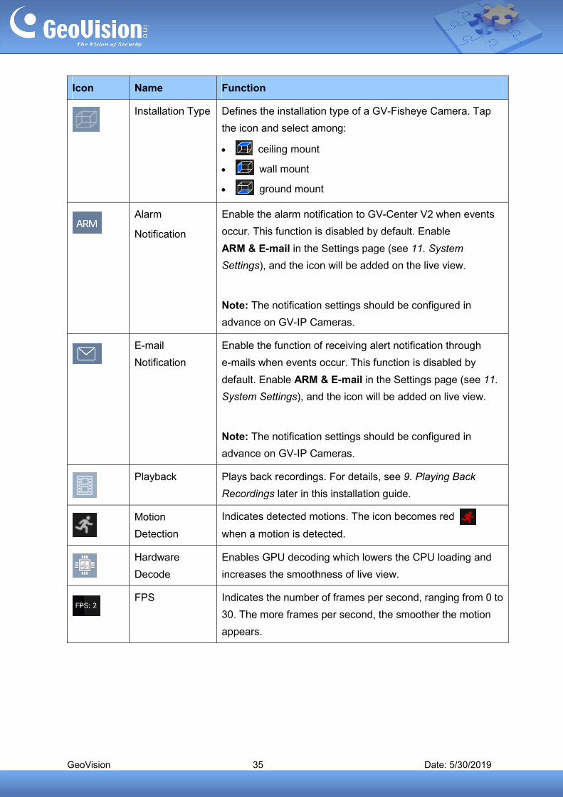
Icon Name Function
Installation Type Defines the installation type of a GV-Fisheye Camera. Tap
the icon and select among:
ceiling mount
wall mount
ground mount
Alarm
Notification
Enable the alarm notification to GV-Center V2 when events
occur. This function is disabled by default. Enable
ARM & E-mail in the Settings page (see 11. System
Settings), and the icon will be added on the live view.
Note: The notification settings should be configured in
advance on GV-IP Cameras.
Notification
Enable the function of receiving alert notification through
e-mails when events occur. This function is disabled by
default. Enable ARM & E-mail in the Settings page (see 11.
System Settings), and the icon will be added on live view.
Note: The notification settings should be configured in
advance on GV-IP Cameras.
Playback Plays back recordings. For details, see 9. Playing Back
Recordings later in this installation guide.
Motion
Detection
Indicates detected motions. The icon becomes red
when a motion is detected.
Hardware
Decode
Enables GPU decoding which lowers the CPU loading and
increases the smoothness of live view.
FPS Indicates the number of frames per second, ranging from 0 to
30. The more frames per second, the smoother the motion
appears.
GeoVision 36 Date: 5/30/2019
Note:
1. The control of enabling or disabling recording is only available for compatible
products and versions. For details, see 2.2 Supported Products for Enabling
Recording.
2. PTZ Panel functions are fully or partially supported by the following GV-IP device:
GV-IP Speed Dome and GV-PTZ Camera: all functions supported
GV-PT Camera: all functions supported except zoom in/out
GV-IP Cameras that support remote focus/zoom adjustment: only support auto
focus, focus in/out and zoom in/out.
3. The microphone function is only supported by GV-IP Cameras and GV-Recording
Server V1.3 or later.
GeoVision 37 Date: 5/30/2019
9. Playing Back Recordings
9.1 Accessing the Recorded Files
Make sure the following functions are enabled ahead to allow remote access from the
GV-Eye:
GV-DVR / NVR / GV-VMS: enable Remote ViewLog Service. See 6.1 Required
Configurations on GV-Software before Connecting.
GV-IP Camera / GV-Video Server / GV-Compact DVR: enable ViewLog Server
Note:
1. If a router or firewall is installed with the remote servers and IP devices, ensure the
corresponding playback port is open. For example, to play back the files from GV-DVR / NVR /
VMS, open port 5552 on the router. For Windows Firewall settings see 6.2 Configuring Windows
Firewall for Communication. For port forwarding and a full list of default port numbers, see 6.3
Port Forwarding.
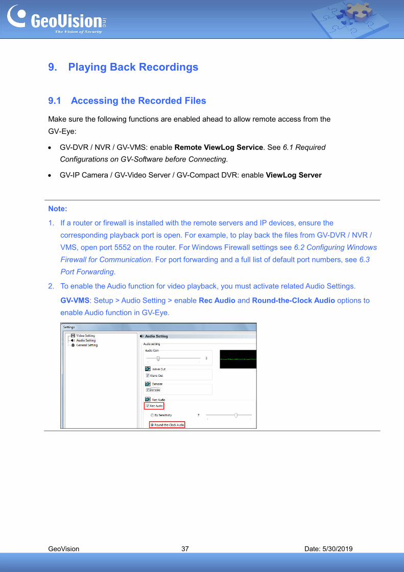
2. To enable the Audio function for video playback, you must activate related Audio Settings.
GV-VMS: Setup > Audio Setting > enable Rec Audio and Round-the-Clock Audio options to
enable Audio function in GV-Eye.
GeoVision 38 Date: 5/30/2019
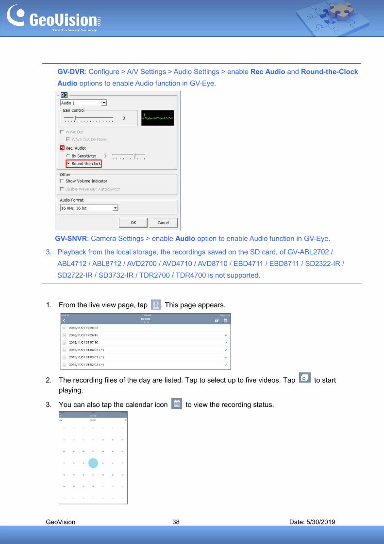
GV-DVR: Configure > A/V Settings > Audio Settings > enable Rec Audio and Round-the-Clock
Audio options to enable Audio function in GV-Eye.
GV-SNVR: Camera Settings > enable Audio option to enable Audio function in GV-Eye.
3. Playback from the local storage, the recordings saved on the SD card, of GV-ABL2702 /
ABL4712 / ABL8712 / AVD2700 / AVD4710 / AVD8710 / EBD4711 / EBD8711 / SD2322-IR /
SD2722-IR / SD3732-IR / TDR2700 / TDR4700 is not supported.
1. From the live view page, tap . This page appears.
2. The recording files of the day are listed. Tap to select up to five videos. Tap to start
playing.
3. You can also tap the calendar icon to view the recording status.
GeoVision 39 Date: 5/30/2019
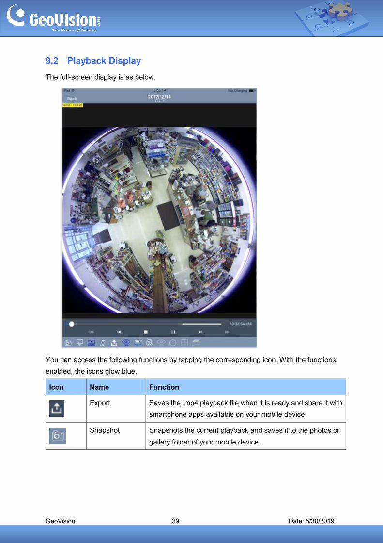
9.2 Playback Display
The full-screen display is as below.
You can access the following functions by tapping the corresponding icon. With the functions
enabled, the icons glow blue.
Icon Name Function
Export Saves the .mp4 playback file when it is ready and share it with
smartphone apps available on your mobile device.
Snapshot Snapshots the current playback and saves it to the photos or
gallery folder of your mobile device.
GeoVision 40 Date: 5/30/2019
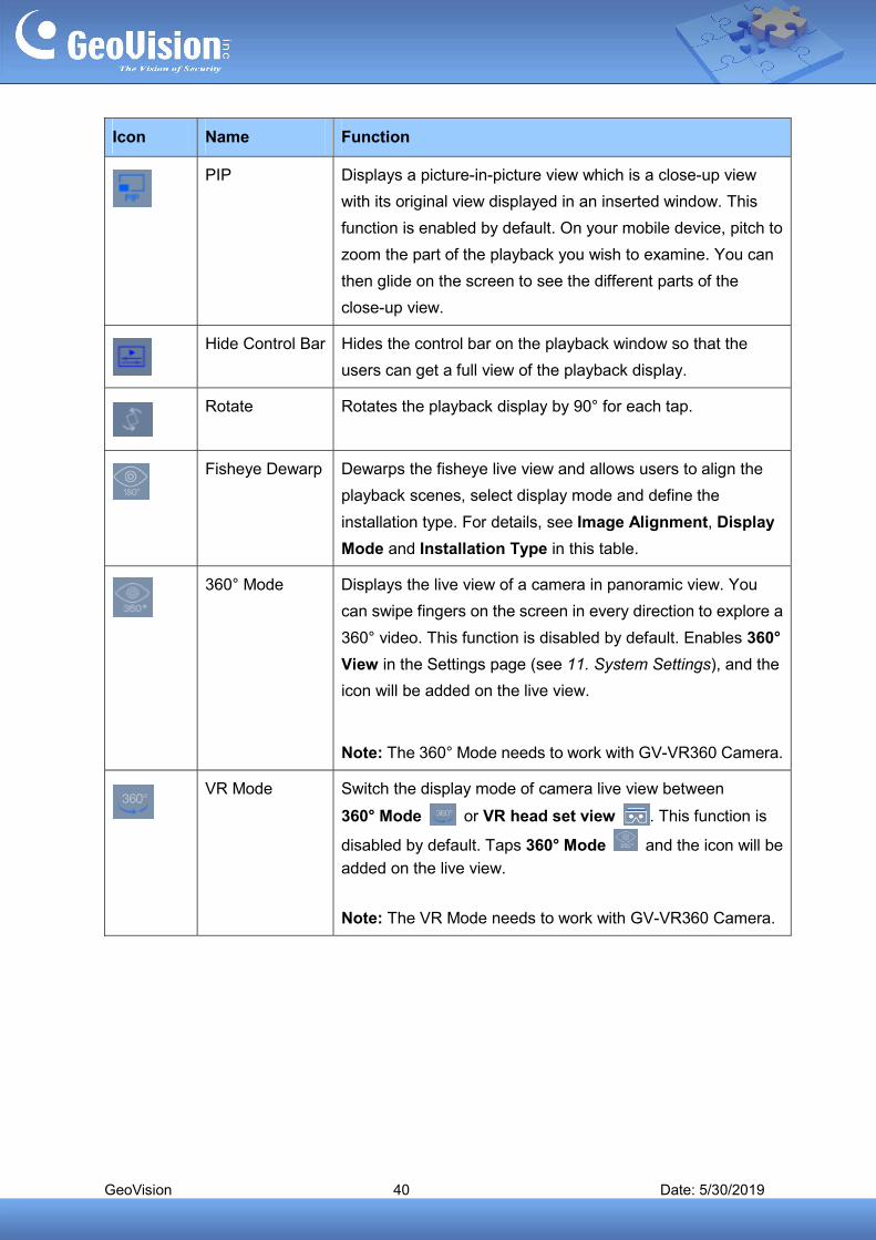
Icon Name Function
PIP Displays a picture-in-picture view which is a close-up view
with its original view displayed in an inserted window. This
function is enabled by default. On your mobile device, pitch to
zoom the part of the playback you wish to examine. You can
then glide on the screen to see the different parts of the
close-up view.
Hide Control Bar Hides the control bar on the playback window so that the
users can get a full view of the playback display.
Rotate Rotates the playback display by 90° for each tap.
Fisheye Dewarp Dewarps the fisheye live view and allows users to align the
playback scenes, select display mode and define the
installation type. For details, see Image Alignment, Display
Mode and Installation Type in this table.
360° Mode Displays the live view of a camera in panoramic view. You
can swipe fingers on the screen in every direction to explore a
360° video. This function is disabled by default. Enables 360°
View in the Settings page (see 11. System Settings), and the
icon will be added on the live view.
Note: The 360° Mode needs to work with GV-VR360 Camera.
VR Mode Switch the display mode of camera live view between
360° Mode or VR head set view . This function is
disabled by default. Taps 360° Mode and the icon will be
added on the live view.
Note: The VR Mode needs to work with GV-VR360 Camera.
GeoVision 41 Date: 5/30/2019
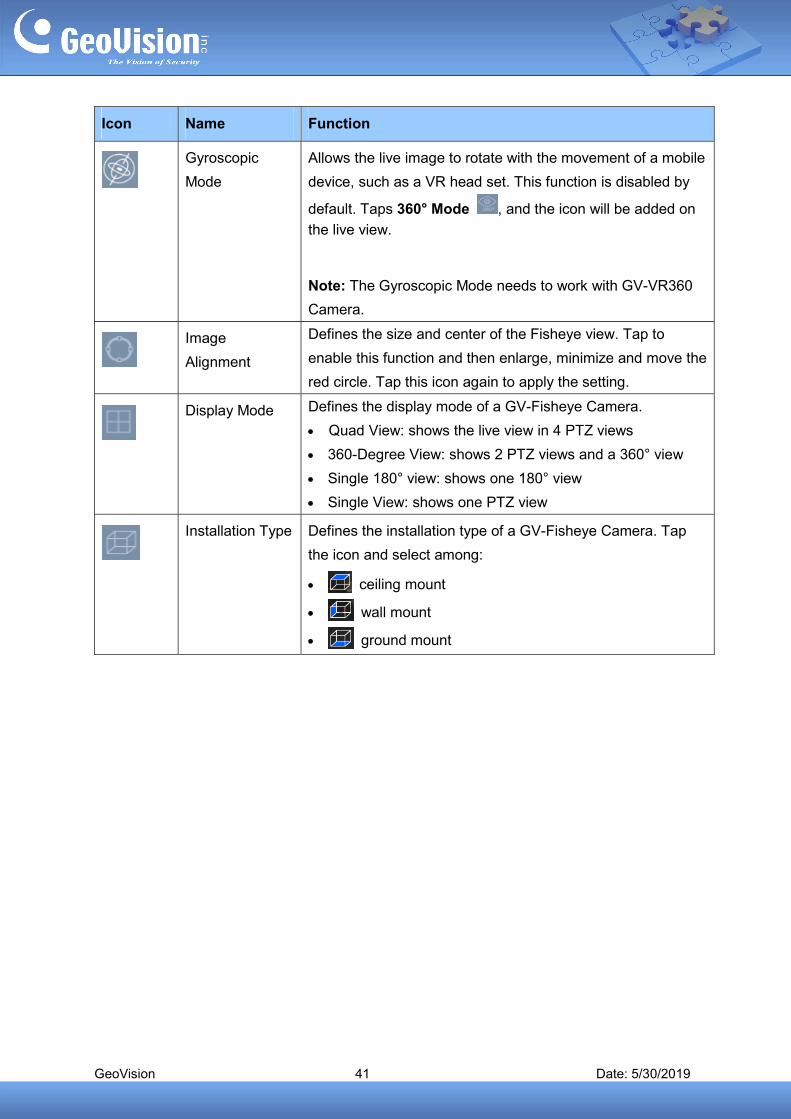
Icon Name Function
Gyroscopic
Mode
Allows the live image to rotate with the movement of a mobile
device, such as a VR head set. This function is disabled by
default. Taps 360° Mode , and the icon will be added on
the live view.
Note: The Gyroscopic Mode needs to work with GV-VR360
Camera.
Image
Alignment
Defines the size and center of the Fisheye view. Tap to
enable this function and then enlarge, minimize and move the
red circle. Tap this icon again to apply the setting.
Display Mode Defines the display mode of a GV-Fisheye Camera.
Quad View: shows the live view in 4 PTZ views
360-Degree View: shows 2 PTZ views and a 360° view
Single 180° view: shows one 180° view
Single View: shows one PTZ view
Installation Type Defines the installation type of a GV-Fisheye Camera. Tap
the icon and select among:
ceiling mount
wall mount
ground mount
GeoVision 42 Date: 5/30/2019
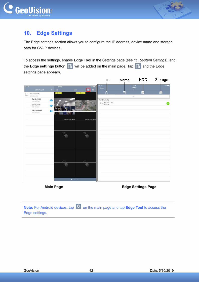
10. Edge Settings
The Edge settings section allows you to configure the IP address, device name and storage
path for GV-IP devices.
To access the settings, enable Edge Tool in the Settings page (see 11. System Settings), and
the Edge settings button will be added on the main page. Tap and the Edge
settings page appears.
Main Page Edge Settings Page
Note: For Android devices, tap on the main page and tap Edge Tool to access the
Edge settings.
GeoVision 43 Date: 5/30/2019
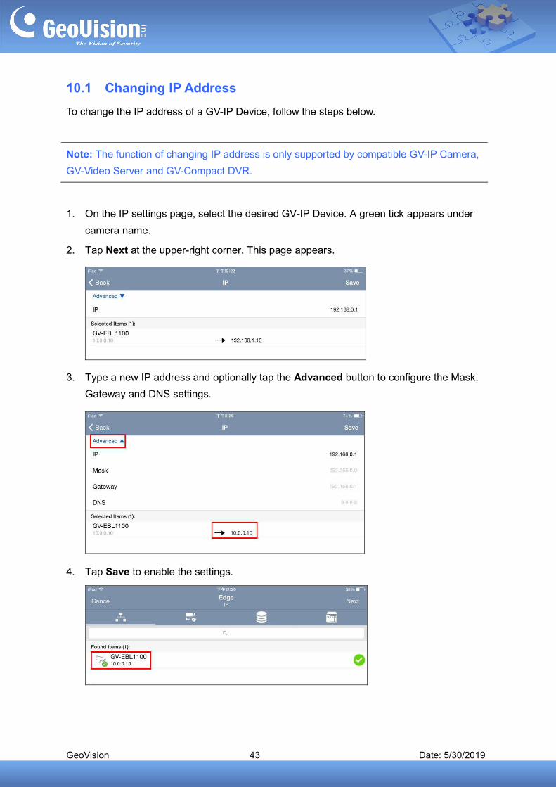
10.1 Changing IP Address
To change the IP address of a GV-IP Device, follow the steps below.
Note: The function of changing IP address is only supported by compatible GV-IP Camera,
GV-Video Server and GV-Compact DVR.
1. On the IP settings page, select the desired GV-IP Device. A green tick appears under
camera name.
2. Tap Next at the upper-right corner. This page appears.
3. Type a new IP address and optionally tap the Advanced button to configure the Mask,
Gateway and DNS settings.
4. Tap Save to enable the settings.

GeoVision 44 Date: 5/30/2019
10.2 Changing Device Name
To change the device name of a GV-IP Device, follow the steps below.
Note: The function of changing device name is only supported by compatible GV-IP
Camera, GV-Video Server and GV-Compact DVR.
1. On the Edge settings page, tap the Name button . The Name settings page
appears.
2. Select the desired GV-IP Device and tap Next. This page appears.
3. Type a new name for the device and tap Save.
4. On the Name settings page, pull to refresh. The device name is updated.
GeoVision 45 Date: 5/30/2019
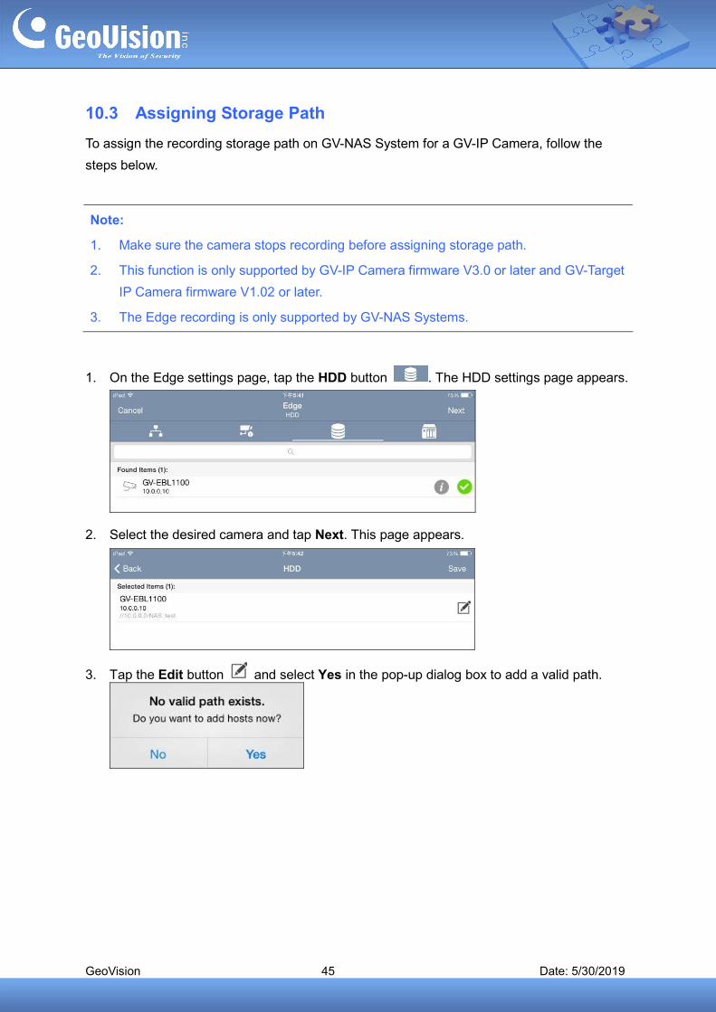
10.3 Assigning Storage Path
To assign the recording storage path on GV-NAS System for a GV-IP Camera, follow the
steps below.
Note:
1. Make sure the camera stops recording before assigning storage path.
2. This function is only supported by GV-IP Camera firmware V3.0 or later and GV-Target
IP Camera firmware V1.02 or later.
3. The Edge recording is only supported by GV-NAS Systems.
1. On the Edge settings page, tap the HDD button . The HDD settings page appears.
2. Select the desired camera and tap Next. This page appears.
3. Tap the Edit button and select Yes in the pop-up dialog box to add a valid path.
GeoVision 46 Date: 5/30/2019
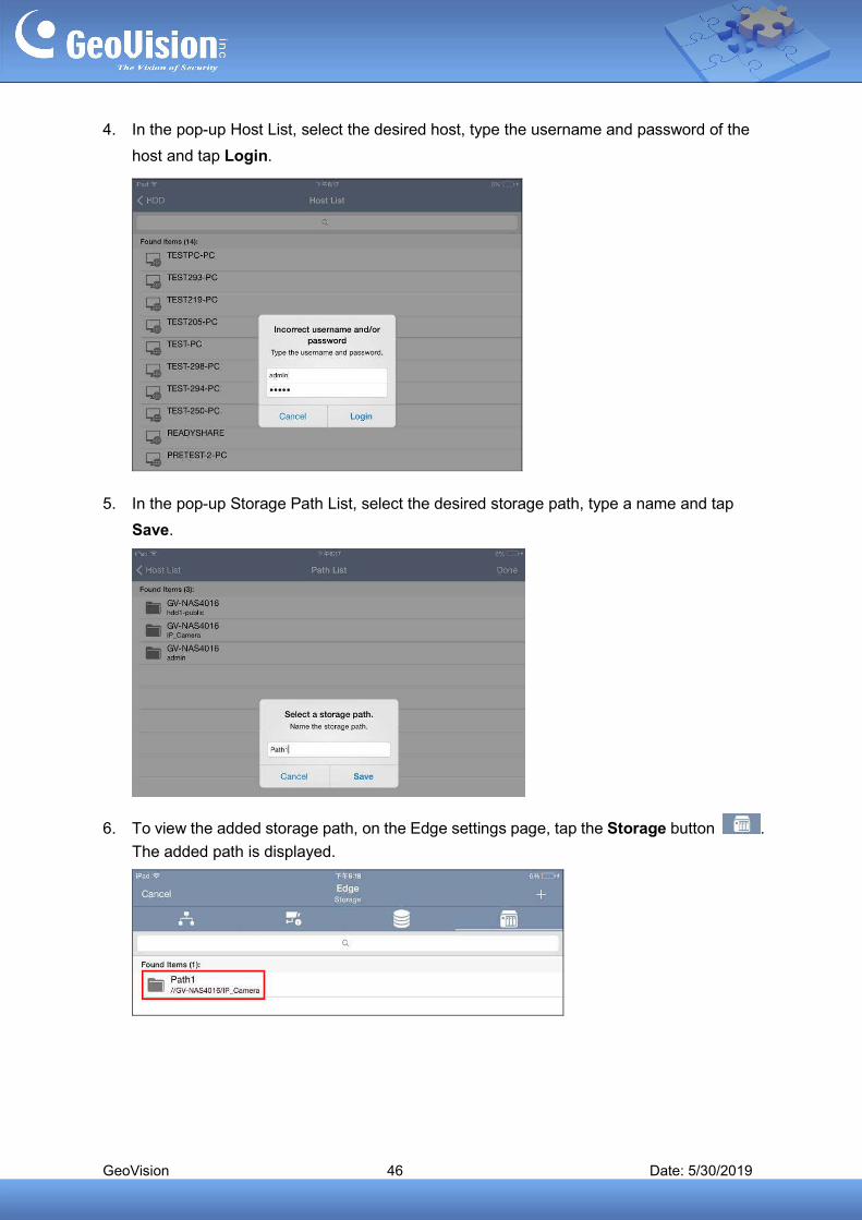
4. In the pop-up Host List, select the desired host, type the username and password of the
host and tap Login.
5. In the pop-up Storage Path List, select the desired storage path, type a name and tap
Save.
6. To view the added storage path, on the Edge settings page, tap the Storage button .
The added path is displayed.
GeoVision 47 Date: 5/30/2019
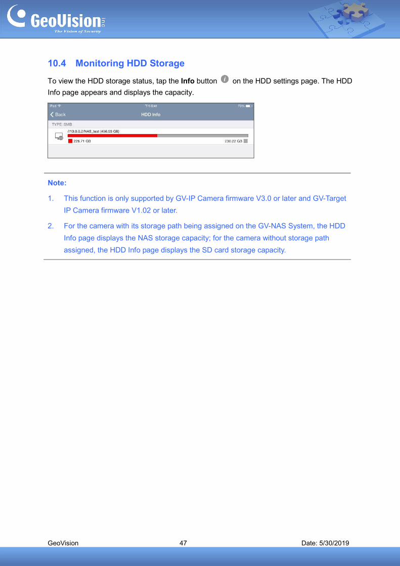
10.4 Monitoring HDD Storage
To view the HDD storage status, tap the Info button on the HDD settings page. The HDD
Info page appears and displays the capacity.
Note:
1. This function is only supported by GV-IP Camera firmware V3.0 or later and GV-Target
IP Camera firmware V1.02 or later.
2. For the camera with its storage path being assigned on the GV-NAS System, the HDD
Info page displays the NAS storage capacity; for the camera without storage path
assigned, the HDD Info page displays the SD card storage capacity.
GeoVision 48 Date: 5/30/2019
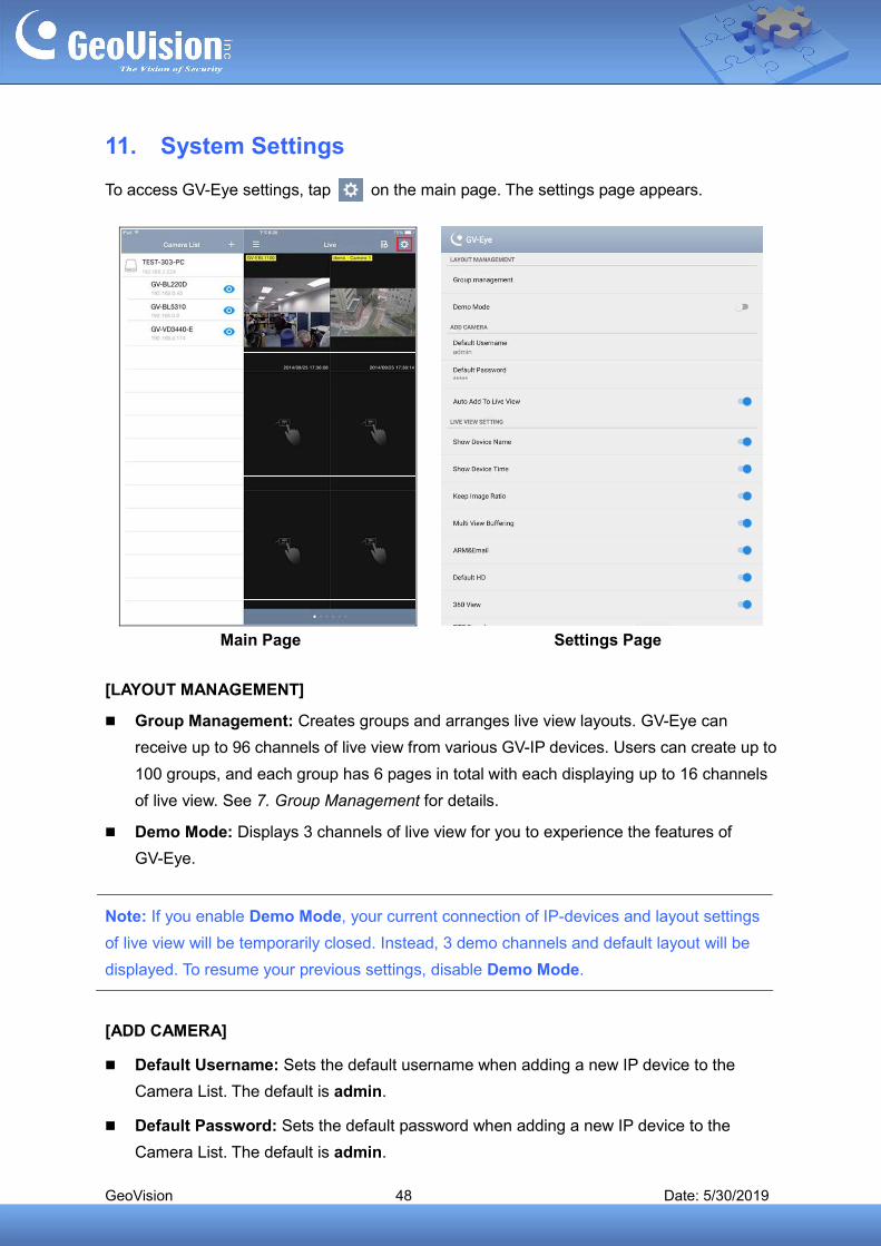
11. System Settings
To access GV-Eye settings, tap on the main page. The settings page appears.
Main Page Settings Page
[LAYOUT MANAGEMENT]
Group Management: Creates groups and arranges live view layouts. GV-Eye can
receive up to 96 channels of live view from various GV-IP devices. Users can create up to
100 groups, and each group has 6 pages in total with each displaying up to 16 channels
of live view. See 7. Group Management for details.
Demo Mode: Displays 3 channels of live view for you to experience the features of
GV-Eye.
Note: If you enable Demo Mode, your current connection of IP-devices and layout settings
of live view will be temporarily closed. Instead, 3 demo channels and default layout will be
displayed. To resume your previous settings, disable Demo Mode.
[ADD CAMERA]
Default Username: Sets the default username when adding a new IP device to the
Camera List. The default is admin.
Default Password: Sets the default password when adding a new IP device to the
Camera List. The default is admin.

GeoVision 49 Date: 5/30/2019
Auto Add to Live View: Automatically displays the added IP devices to live view. This
function is disabled by default.
[LIVE VIEW SETTING]
Show Device Name: Displays device name on live view.
Show Device Time: Displays device time on live view.
Keep Image Ratio: Displays the live view in proportion to the device’s resolution.
Multi View Buffering: Enhances the smoothness of live view with multiple divisions. Note
this function is for Android devices only.
ARM & EMAIL: Displays the alarm invocation and e-mail notification icons on live view.
Default HD: Displays the live view in HD quality video. This function is enabled by default.
360 View: Enables the panoramic view.
PTZ Speed: Changes the PTZ speed. Speed 1 is the slowest and speed 5 the fastest.
Delete All Entries on Camera List: Click to delete all the entries from the Camera List of
all groups.
Export Camera List: Export the current camera list as a QR code image to the internal
storage of smartphone.
Import Camera List: Scan the QR code containing the camera list, previously exported,
to be loaded into GV-Eye.
Edge Tool: Displays the edge settings icon on live view.
[ACCOUNT MANAGEMENT]
Add a binding account: Logs into a GV-Relay Account, see 5. GV-Relay QR Code.
[PLAYBACK SETTING]
Audio: Enable Audio function for video playback.
Hardware Acceleration: Enable Hardware Acceleration function to increase the
smoothness of playback. Note this function is enabled by default and for Android devices
only.
[SYSTEM SETTING]
Disable Screen Off: Turns off sleep mode of the mobile device when the GV-Eye is
running.
GeoVision 50 Date: 5/30/2019
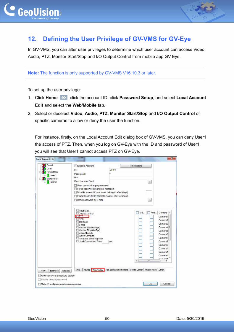
12. Defining the User Privilege of GV-VMS for GV-Eye
In GV-VMS, you can alter user privileges to determine which user account can access Video,
Audio, PTZ, Monitor Start/Stop and I/O Output Control from mobile app GV-Eye.
Note: The function is only supported by GV-VMS V16.10.3 or later.
To set up the user privilege:
1. Click Home , click the account ID, click Password Setup, and select Local Account
Edit and select the Web/Mobile tab.
2. Select or deselect Video, Audio, PTZ, Monitor Start/Stop and I/O Output Control of
specific cameras to allow or deny the user the function.
For instance, firstly, on the Local Account Edit dialog box of GV-VMS, you can deny User1
the access of PTZ. Then, when you log on GV-Eye with the ID and password of User1,
you will see that User1 cannot access PTZ on GV-Eye.


![東空販売株式会社型式 GV-15S GV-30S GV-40S GV-60S GV-120S GV-200S GV-300S GV-400S 本体クラス の目安[ton] 1.2~3 3~4 4~5 6~8 12~14 20~22 30~35 40~45](https://img.pdfslide.net/doc/110x75/5fbcb589660a9a3349511e44/cec-gv-15s-gv-30s-gv-40s-gv-60s-gv-120s-gv-200s-gv-300s.jpg)