Embed Size (px)
Citation preview

GV55LITE User manual
TRACGV3SUM001 - 1 -
GPS Locator GV55 User Manual TRACGV55LITEUM001
Revision: 1.01
Hhttp://www.queclink.com
GV55 User manual
TRACGV55LITEUM001 - 2 -
Document Title GV55 User Manual
Version 1.01
Date 2012-7-31
Status Release
Document Control ID TRACGV55UM001
General Notes Queclink offers this information as a service to its customers, to support application and engineering efforts that use the products designed by Queclink. The information provided is based upon requirements specifically provided to Queclink by the customers. Queclink has not undertaken any independent search for additional relevant information, including any information that may be in the customer’s possession. Furthermore, system validation of this product designed by Queclink within a larger electronic system remains the responsibility of the customer or the customer’s system integrator. All specifications supplied herein are subject to change. WARNING: Users must maintain a separation distance of at least 20cm from the EUT to satisfy RF exposure compliance. Copyright This document contains proprietary technical information which is the property of Queclink Limited., copying of this document and giving it to others and the using or communication of the contents thereof, are forbidden without express authority. Offenders are liable to the payment of damages. All rights reserved in the event of grant of a patent or the registration of a utility model or design. All specification supplied herein are subject to change without notice at any time. GV55 has been tested and found to comply with the limits for a Class B digital device, pursuant to part 15 of the FCC Rules. This device complies with part 15B, part 22 and part 24 of the FCC rules. Operation is subject to the following two conditions: (1) this device may not cause harmful interference (2) this device must accept any interference, including interference that may cause undesired operation. Power Output is ERP for Part 22 and EIRP for Part 24.End-users and installers must be provided with antenna installation instructions and transmitter operating conditions for satisfying RF exposure compliance. GV55 FCC IDENTIFIER: YQD-GV55 Copyright © Shanghai Queclink Wireless Solutions Co., Ltd. 2012

GV55 User manual
TRACGV55LITEUM001 - 3 -
Contents
Contents ............................................................................................................................................3 1 Introduction....................................................................................................................................7
1.1. Reference.............................................................................................................................7 1.2. Terms and Abbreviations.....................................................................................................7
2 Product Overview ..........................................................................................................................8 2.1. Check Part List ....................................................................................................................8 2.2. Parts List..............................................................................................................................9 2.3. Interface Definition .............................................................................................................9 2.4. GV55 User Cable Colour ..................................................................................................10
3 .Getting Started ............................................................................................................................11 3.1. Opening the Case ..............................................................................................................11 3.2. Closing the Case................................................................................................................11 3.3. Installing a SIM Card ........................................................................................................12 3.4. Power Connection .............................................................................................................12 3.5. Ignition Detection..............................................................................................................13 3.6. Digital Inputs.....................................................................................................................13 3.7. Digital Outputs ..................................................................................................................14 3.8. Device Status LED ............................................................................................................15
GV55 User manual
TRACGV55LITEUM001 - 4 -
Table Index
TABLE 1. GV55 PROTOCOL REFERENCE..................................................................................7 TABLE 2. TERMS AND ABBREVIATIONS..................................................................................7 TABLE 3. PART LIST......................................................................................................................9 TABLE 4. DESCRIPTION OF 6 PIN CONNECTIONS..................................................................9 TABLE 5. GV55 USER CABLE COLOUR DEFINITION ...........................................................10 TABLE 6. ELECTRICAL CHARACTERISTICS OF IGNITION DETECTION .........................13 TABLE 7. ELECTRICAL CHARACTERISTICS OF THE DIGITAL INPUTS ...........................13 TABLE 8. ELECTRICAL CHARACTERISTICS OF DDIGITAL OUTPUTS .............................14 TABLE 9. DEFINITION OF DEVICE STATUS AND LED .........................................................16
GV55 User manual
TRACGV55LITEUM001 - 5 -
Figure Index
FIGURE 1. APPEARANCE OF GV55 ..............................................................................................8 FIGURE 2. THE 6 PIN CONNECTOR ON THE GV55....................................................................9 FIGURE 3. OPENING THE CASE.................................................................................................. 11 FIGURE 4. CLOSING THE CASE.................................................................................................. 11 FIGURE 5. SIM CARD INSTALLATION.......................................................................................12 FIGURE 6. TYPICAL POWER CONNECTION.............................................................................12 FIGURE 7. TYPICAL IGNITION DETECTION ............................................................................13 FIGURE 8. TYPICAL DIGITAL INPUT CONNECTION ..............................................................14 FIGURE 9. DIGITAL OUTPUT INTERNAL DRIVE CIRCUIT....................................................14 FIGURE 10. TYPICAL CONNECTION WITH RELAY ..................................................................15 FIGURE 11. TYPICAL CONNECTION WITH LED .......................................................................15 FIGURE 12. GV55 LED ON THE CASE..........................................................................................16
GV55 User manual
TRACGV55LITEUM001 - 6 -
Revision History
Revision Date Author Description of change 1.01 2012-7-31 Owen Feng Initial

GV55 User manual
TRACGV55LITEUM001 - 7 -
1 Introduction
The GV55 is a powerful GPS locator designed for vehicle or asset tracking. It has superior receiver sensitivity, fast TTFF (Time to First Fix) and supports Dual-Band GSM frequencies 850/900/1800/1900, its location can be monitored in real time or be periodically tracked by a backend server or other specified terminals. The GV55 has multiple input/output interfaces that can be used for monitoring or controlling external devices. Based on the integrated @Track protocol, the GV55 can communicate with a backend server through the GPRS/GSM network to transfer reports of Emergency, geo-fence boundary crossings, low backup battery or scheduled GPS position as well as many other useful functions. Users can also use GV55 to monitor the status of a vehicle and control the vehicle by its external relay output. System Integrators can easily setup their tracking systems based on the full-featured @Track protocol.
Table 1. GV55 Protocol Reference
SN Document name Remark [1] GV55 @Track Air Interface Protocol The air protocol interface between
GV55 and backend server.
Table 2. Terms and Abbreviations
Abbreviation Description AGND Analog Ground AIN Analog Input DIN Digital Input DOUT Digital Output GND Ground MIC Microphone RXD Receive Data TXD Transmit Data SPKN Speaker Negative SPKP Speaker Positive
1.1. Reference
1.2. Terms and Abbreviations
GV55 User manual
TRACGV55LITEUM001 - 8 -
2 Product Overview
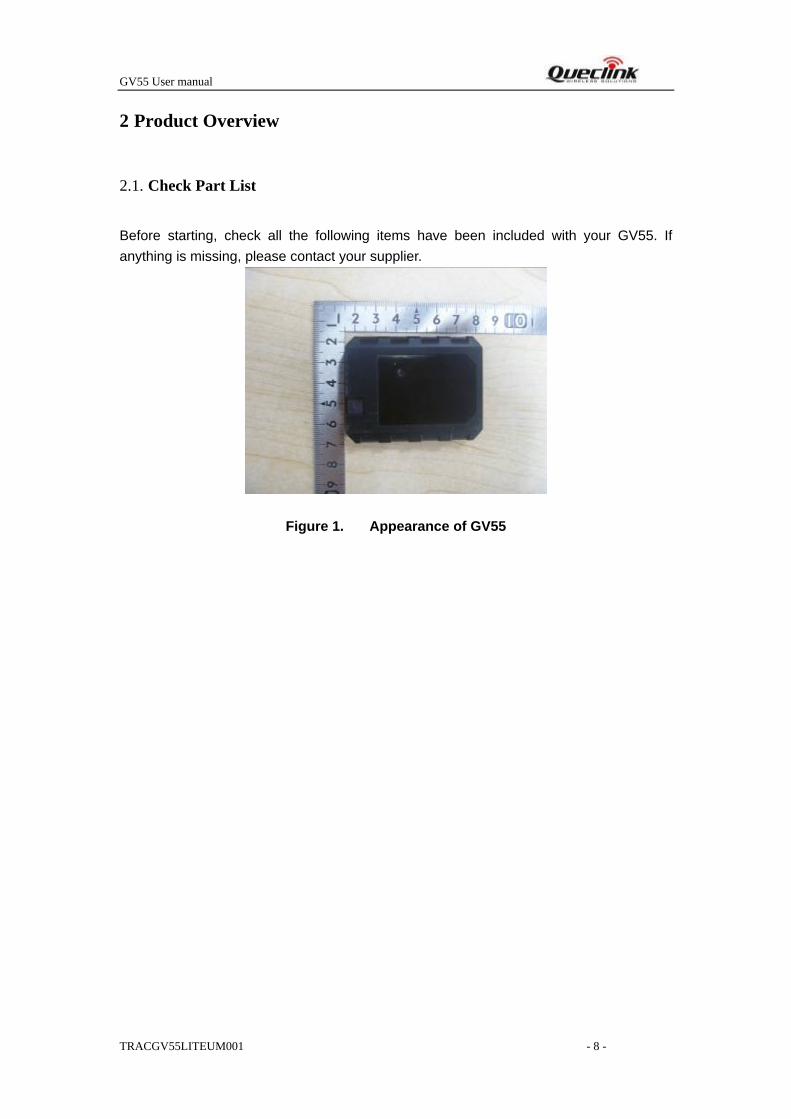
Before starting, check all the following items have been included with your GV55. If anything is missing, please contact your supplier.
Figure 1. Appearance of GV55
2.1. Check Part List
GV55 User manual
TRACGV55LITEUM001 - 9 -
Table 3. Part List
Name Picture GV55 Locator 63mm*50mm*13.2mm User Cable
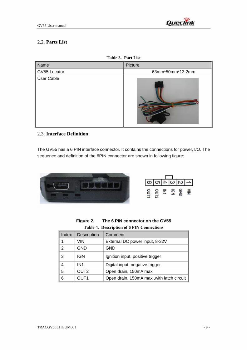
The GV55 has a 6 PIN interface connector. It contains the connections for power, I/O. The sequence and definition of the 6PIN connector are shown in following figure:
Figure 2. The 6 PIN connector on the GV55 Table 4. Description of 6 PIN Connections
Index Description Comment 1 VIN External DC power input, 8-32V 2 GND GND
3 IGN Ignition input, positive trigger
4 IN1 Digital input, negative trigger 5 OUT2 Open drain, 150mA max 6 OUT1 Open drain, 150mA max ,with latch circuit
2.2. Parts List
2.3. Interface Definition
GV55 User manual
TRACGV55LITEUM001 - 10 -
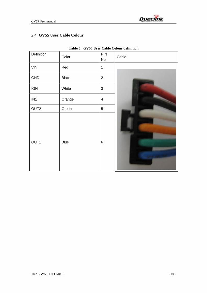
Table 5. GV55 User Cable Colour definition Definition
Color PIN No
Cable
VIN Red 1
GND Black 2
IGN White 3
IN1 Orange 4
OUT2 Green 5
OUT1 Blue 6
2.4. GV55 User Cable Colour
GV55 User manual
TRACGV55LITEUM001 - 11 -
3 .Getting Started
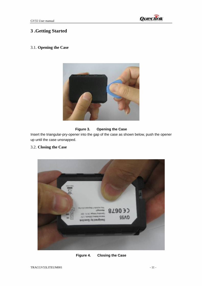
Figure 3. Opening the Case Insert the triangular-pry-opener into the gap of the case as shown below, push the opener up until the case unsnapped.
Figure 4. Closing the Case
3.1. Opening the Case
3.2. Closing the Case
GV55 User manual
TRACGV55LITEUM001 - 12 -
Place the cover on the bottom in the position as shown in the following figure. Slide the cover against the direction of the arrow until it snapped.
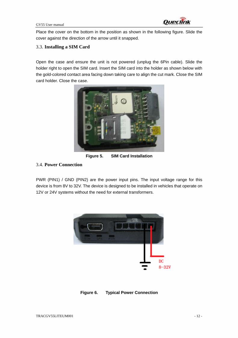
Open the case and ensure the unit is not powered (unplug the 6Pin cable). Slide the holder right to open the SIM card. Insert the SIM card into the holder as shown below with the gold-colored contact area facing down taking care to align the cut mark. Close the SIM card holder. Close the case.
Figure 5. SIM Card Installation
PWR (PIN1) / GND (PIN2) are the power input pins. The input voltage range for this device is from 8V to 32V. The device is designed to be installed in vehicles that operate on 12V or 24V systems without the need for external transformers.
Figure 6. Typical Power Connection
3.3. Installing a SIM Card
3.4. Power Connection
GV55 User manual
TRACGV55LITEUM001 - 13 -
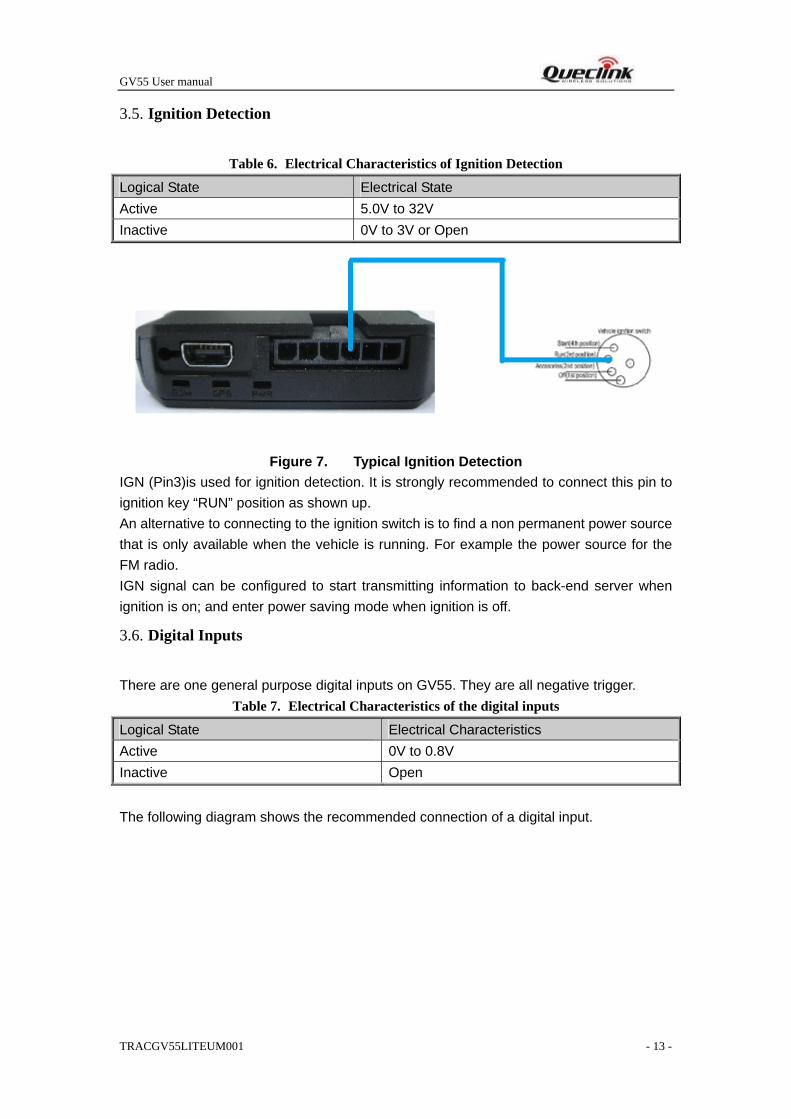
Table 6. Electrical Characteristics of Ignition Detection
Logical State Electrical State Active 5.0V to 32V Inactive 0V to 3V or Open
Figure 7. Typical Ignition Detection IGN (Pin3)is used for ignition detection. It is strongly recommended to connect this pin to ignition key “RUN” position as shown up. An alternative to connecting to the ignition switch is to find a non permanent power source that is only available when the vehicle is running. For example the power source for the FM radio. IGN signal can be configured to start transmitting information to back-end server when ignition is on; and enter power saving mode when ignition is off.
There are one general purpose digital inputs on GV55. They are all negative trigger. Table 7. Electrical Characteristics of the digital inputs
Logical State Electrical Characteristics Active 0V to 0.8V Inactive Open
The following diagram shows the recommended connection of a digital input.
3.5. Ignition Detection
3.6. Digital Inputs
GV55 User manual
TRACGV55LITEUM001 - 14 -
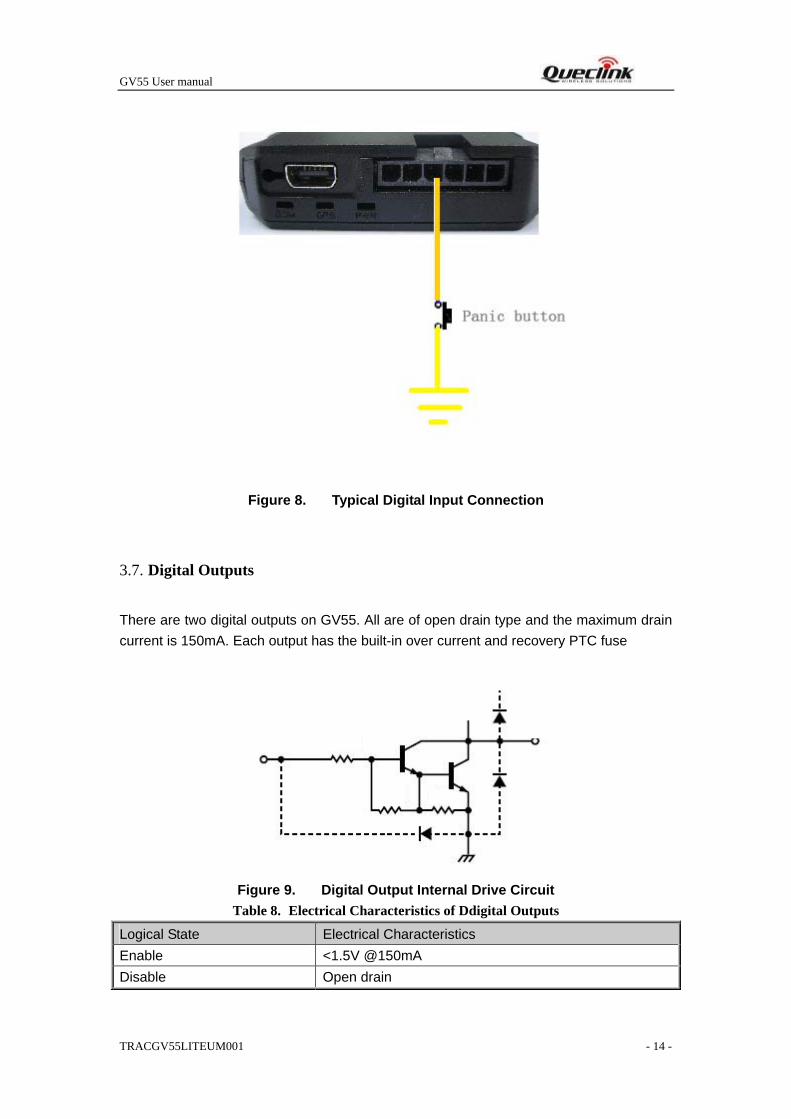
Figure 8. Typical Digital Input Connection
There are two digital outputs on GV55. All are of open drain type and the maximum drain current is 150mA. Each output has the built-in over current and recovery PTC fuse
Figure 9. Digital Output Internal Drive Circuit
Table 8. Electrical Characteristics of Ddigital Outputs
Logical State Electrical Characteristics Enable <1.5V @150mA Disable Open drain
3.7. Digital Outputs

GV55 User manual
TRACGV55LITEUM001 - 15 -
Figure 10. Typical Connection with Relay
Figure 11. Typical Connection with LED
Note: 1 - OUT1 will latch the output state during reset. 2- All outputs are internally without pulled up to PWR pin by a diode. So an external flyback diode is needed when the output is connected to an inductive load.
3.8. Device Status LED
GV55 User manual
TRACGV55LITEUM001 - 16 -
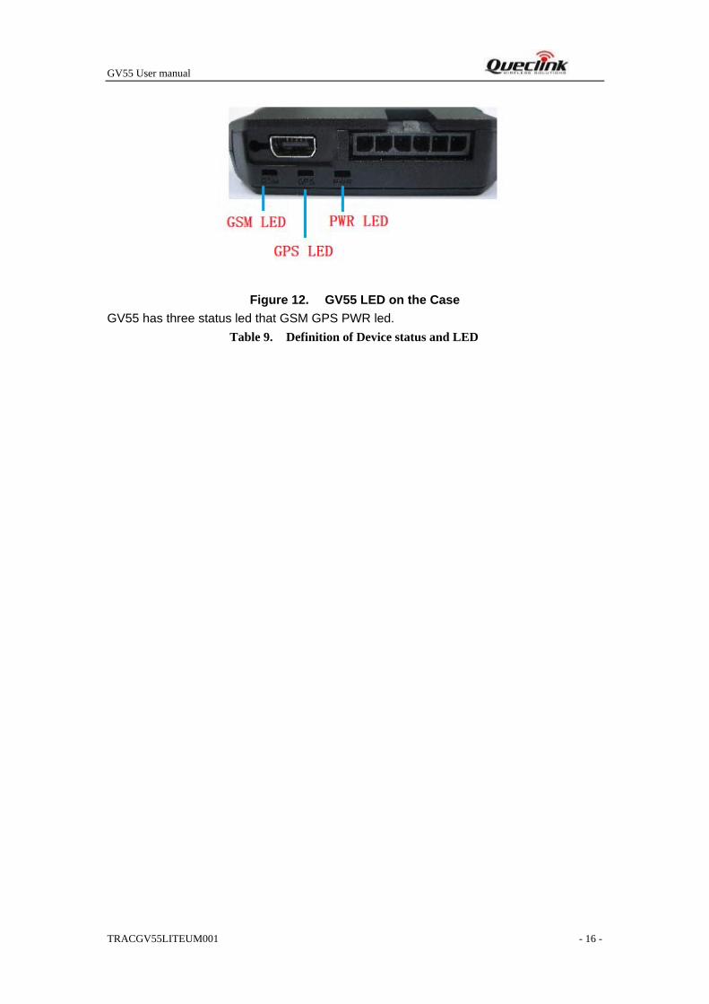
Figure 12. GV55 LED on the Case GV55 has three status led that GSM GPS PWR led.
Table 9. Definition of Device status and LED

GV55 User manual
TRACGV55LITEUM001 - 17 -
Note:
1 - GSM LED cannot be configured. 2 - GPS LED and PWR LED can be configured to turn off after a period of time using the configuration tool 3 - Fast flashing is about 60ms ON/ 780ms OFF 4 - Slow flashing is about 60ms ON/ 1940ms OFF
LED Device status LED status Device is searching GSM network Fast flashing
(Note3) Device has registered to GSM network. Slow flashing
(Note4)
GSM (note1)
SIM card needs pin code to unlock. ON GPS chip is powered off OFF GPS sends no data or data format error. Slow flashing
GPS chip is searching GPS info. Fast flashing
GPS (note 2)
GPS chip has gotten GPS info. ON No external power and internal battery voltage is lower than 3.35V.
OFF
No external power and internal battery voltage is below 3.5V.
Slow flashing
External power in and internal battery is charging Fast flashing
PWR (note 2)
External power in and internal battery is fully charged
ON


![Catalogue FLYBACK Equivalent - [PDF Document] FLYBACK Equivalent FlyBack Equivalent flyback reemplazo conversor Flyback tv fly-back Flyback Tester Flyback Converter conversor Flyback](https://img.pdfslide.net/doc/110x75/5a832a447f8b9a9d308e9416/catalogue-flyback-equivalent-pdf-document-flyback-equivalent-flyback-equivalent.jpg)