Embed Size (px)
Citation preview

GWR Steam Railmotor
Contents
Introduction ........................................................................................................................................ 2
Features ............................................................................................................................................... 3
Background ......................................................................................................................................... 4
Scenarios ............................................................................................................................................. 6
Control Modes .................................................................................................................................... 8
Driving Cab Controls ........................................................................................................................... 9
Rear Cab (Vestibule) Controls ........................................................................................................... 26
Vestibule Driving in Advanced Mode ............................................................................................... 35
Locomotive Numbering .................................................................................................................... 38
Ground Platforms and Scenario Objects .......................................................................................... 39
Acknowledgements ........................................................................................................................... 42
P a g e | 2
Copyright Victory Works 2014, all rights reserved Release Version 1.0
Introduction
Thank you for purchasing the GWR Steam Railmotor DLC for Train Simulator.
The locomotive design is unusual, albeit the forerunner of more modern diesel and electric
multiple units, and in Advanced Mode should provide an experience like no other to date.
Please read the manual thoroughly, especially to get the best from Advanced Mode, and enjoy
reliving a piece of railway history.
All the best,
Pete Gillam (karma99 on Steam and various forums)
Victory Works CLICK FOR BLOG - INSIGHT INTO NEW RELEASES, UPDATES AND GENERAL TS NEWS CLICK FOR FACEBOOK
P a g e | 3
Copyright Victory Works 2014, all rights reserved Release Version 1.0
Features
Unique style of steam locomotive provides unique driving challenges
Simple, standard and advanced driving modes
Xbox controller support SIMPLE AND STANDARD MODES ONLY
Two completely different driving cabs STANDARD AND ADVANCED MODE ONLY
Two very different driving experiences ADVANCED MODE ONLY
Simulated steam chest ADVANCED MODE ONLY
Cylinder cock management when driving from the front cab ADVANCED MODE ONLY
Boiler management with priming possible ADVANCED MODE ONLY
Notched reverser (front cab) and regulator (rear cab) ADVANCED MODE ONLY
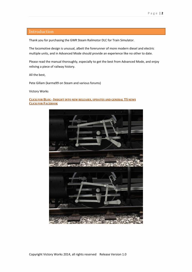
Animated valve gear with two forward and two reverse positions
Dynamic steam and smoke colour and quantity
Dynamic driver location based on direction of travel
Opening cab doors, windows and roof hatch
“Hand operated” window wipers ADVANCED MODE ONLY
Lighting throughout the carriage and additional firebox effects
Custom sound sets for each driving cab
Dynamic destination boards can be set to any location via scenario locomotive
number (up to 12 characters)
Refuelling via coal sacks and water hose
Ground platform support with animated steps using special scenario marker –
requires ground level platforms to be added/included with route
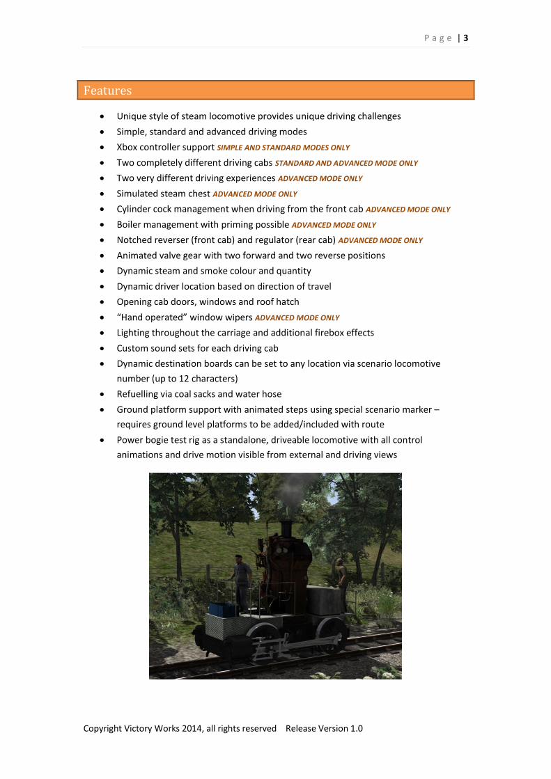
Power bogie test rig as a standalone, driveable locomotive with all control
animations and drive motion visible from external and driving views
P a g e | 4
Copyright Victory Works 2014, all rights reserved Release Version 1.0
Background
The GWR railmotor came into existence at a time when the railways were starting to encounter
competition from electric street tramcars and motor buses. A better service was needed urgently
on suburban routes and branch lines and after success was had with steam railmotor units by the
London & South Western Railway in Southsea the GWR followed suit.
The design was similar to a standard passenger coach but with a boiler attached directly to a
driving bogie at one end as a “standalone” power unit and a rolling bogie with a rear vestibule
cab at the other for driving in reverse.
In total the Great Western Railway built 99 steam railmotors, numbered from 1 to 99 between
1903 and 1908. There were many designs and the locomotive represented here is of the Q
diagram which were numbered from 73 to 80 and built in 1906.
There were actually 112 power units built and these could be exchanged during maintenance.
The design provided some unique challenges, primarily being the distance between the driver
and the fireman when being driven from the rear cab (vestibule). This normally symbiotic
relationship had to be conducted via a series of bell pushes and the fireman's duties were greatly
increased when the driver was at the other end doing little more than accelerating or braking.
Meanwhile the driving cab was far from standard with a vertically mounted boiler providing
power directly to the rotating bogie below it via Walschaerts gear which meant that the driver’s
and fireman’s controls, usually mounted on a static back head, would rotate with the
boiler/bogie combination making coaling while in motion very difficult. In addition to the
movement the firebox hole was very small, very low down (slightly below the floor) and when
the firebox doors were opened while the locomotive was moving the extreme draught would
cause the fire to lose all temperature and could also cause the pipes in the boiler to crack. Due to
these reasons the steam railmotors were only coaled during stops.
The railmotor also had other unusual features such as walk-over seats which could be flipped for
travel in either direction, a handbrake in both cabs and sander on both the powered and rolling
bogies, retractable steps for stopping at ground level stations so the passengers could ascend to
the doorway and a hand operated windscreen wiper in both cabs.
Despite all these oddities the railmotors lives were short lived due to other issues.
The relatively small passenger accommodation was a problem during busy periods. To counter
this, trailers were constructed with remote cabs and linked driving equipment however after
adding the extra weight of these the power from the small boiler was insufficient, especially on
longer routes that had steep gradients. The need for frequent servicing of all steam engines
meant that the railmotors could be unavailable when required for frequent passenger services
and due to the dirty nature of steam locomotive maintenance it was found that keeping the
passenger areas clean was very difficult and time consuming.
P a g e | 5
Copyright Victory Works 2014, all rights reserved Release Version 1.0
Most railmotors were converted into auto-coaches which also had remote cabs but were
attached to a standard steam locomotive fitted with special linking equipment and the power
units were scrapped. An Auto-train had the benefits of a railmotor but was much more flexible
and easier to maintain. The first GWR railmotor was withdrawn in 1914 and the last in 1935.
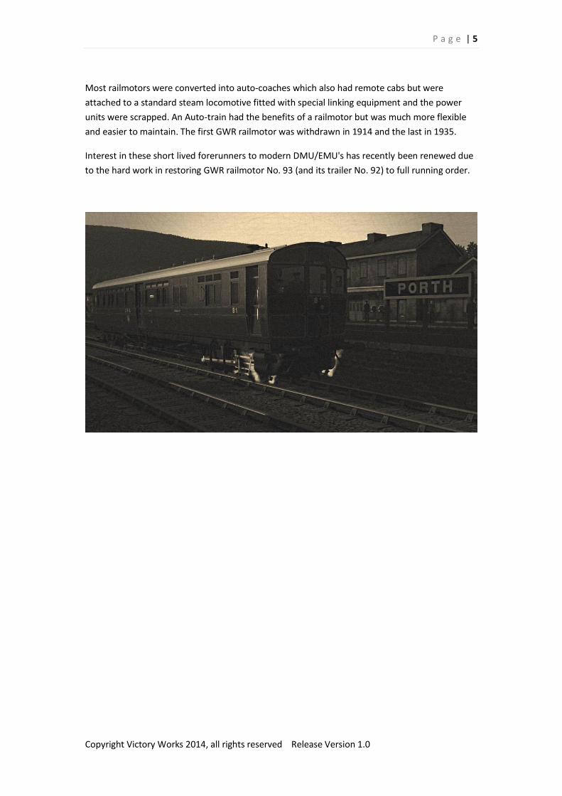
Interest in these short lived forerunners to modern DMU/EMU's has recently been renewed due
to the hard work in restoring GWR railmotor No. 93 (and its trailer No. 92) to full running order.
P a g e | 6
Copyright Victory Works 2014, all rights reserved Release Version 1.0
Scenarios
5 scenarios are included for the West Somerset Railway DLC.
More scenarios will be added to the Steam Workshop, including some using custom versions of
routes with added ground platforms (see section below)
http://steamcommunity.com/profiles/76561197993421982/myworkshopfiles/
The locomotive running in both directions and bogie test rig are also available in Quick Drive.
SRM 1] What on Earth?
After a lot of hard work the power bogie for GWR Steam Railmotor No. 80 has been restored to running condition and it’s now time for testing. You’re task today is to drive it - very carefully - from the shed at Washford to Minehead for
further inspection before it can be added to the coach frame.
SRM 2] Trials and Tribulations
Railmotor No. 80 has been restored and is ready for her main test run. Your job is to make sure everything is working correctly and deal with any problems that happen
along the way.
SRM 3] The Big Day
Today is a very special day. It is the inaugural run of GWR Steam Railmotor No. 80 which has been restored through much hard work and is going to drive as much of the passenger route of 1911 from Minehead to Taunton as possible. You are tasked with the first part from Minehead to Williton where another driver will take over. As well as your passengers who are all dressed in period costume there are lots of other activities
on the railway today for photo opportunities including a special freight train.
SRM 4] And the rain came down – There
A wet Saturday in October and you are driving the 14.20 service to Minehead stopping at all
stations between Bishops Lydeard and Minehead on the real WSR 2013 Green timetable.
P a g e | 7
Copyright Victory Works 2014, all rights reserved Release Version 1.0
SRM 5] And the rain came down – Back
Drive Railmotor No. 80 backwards using the rear vestibule cab to Bishops Lydeard using the real WSR 2013 Green timetable. This is the return journey on the same wet October Saturday. It looks like the rain might have stopped for the moment though.
This scenario is especially challenging in Advanced Mode
Please read the appropriate section below for full details on this realistic simulation option.
P a g e | 8
Copyright Victory Works 2014, all rights reserved Release Version 1.0
Control Modes
There are 3 ways to drive the Steam Railmotor
Simple Mode
This is selected using the menu in Train Simulator and provides a simple stop/go,
forwards/backwards set of controls via the simulators built in HUD.
Standard Mode
This is the default mode if you choose to drive in Expert mode using the Train Simulator menu.
The locomotive will operate with more complex controls and can be driven just using the F4 HUD
or an Xbox controller.
Advanced Mode
This is an advanced mode for those who want a more realistic experience and introduces
features such as condensed water in the cylinders, overfilling the boiler, notching of the reverser
or regulator and a completely different driving experience in the rear vestibule. To achieve these
extra functions using a keyboard is required, although this can be used in conjunction with
mouse operation of the F4 HUD.
Auto-fireman is best set to OFF to use this mode. An “intelligent” fireman will take over whilst
driving from the vestibule; from the driving cab it’s just more fun for you!
To enter Advanced Mode you can press Control A at any time, and this will also turn it off again.
The Advanced Mode controls and features are denoted below.
Hard-core Mode
There is no setting for this but if you use the F3 HUD (or no HUD at all!) and drive in Advanced
Mode using only the cab controls via the mouse (no keyboard or Xbox controller) then you can
consider yourself hard-core! You probably spend your spare time patting your head, rubbing
your stomach and solving quadratic equations at the same time, and Victory Works salute you!
P a g e | 9
Copyright Victory Works 2014, all rights reserved Release Version 1.0
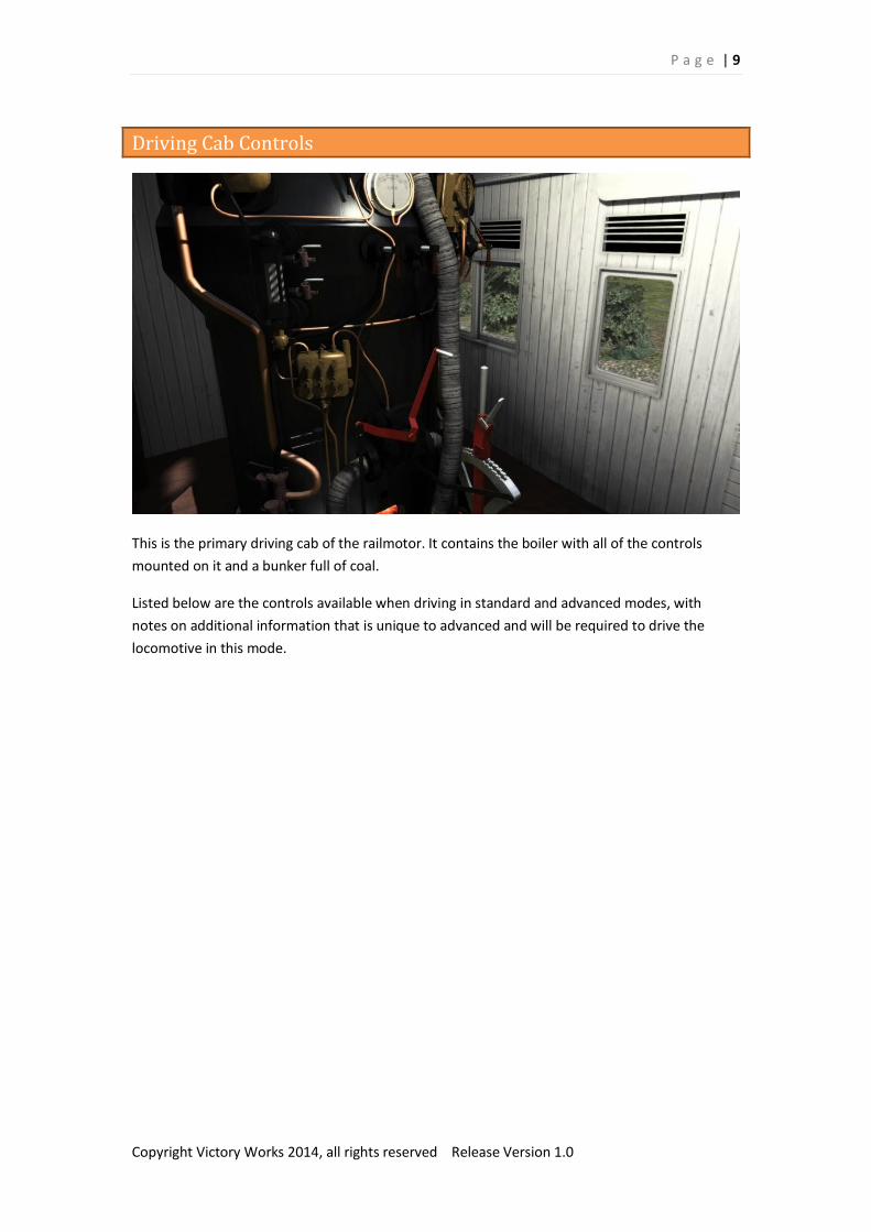
Driving Cab Controls
This is the primary driving cab of the railmotor. It contains the boiler with all of the controls
mounted on it and a bunker full of coal.
Listed below are the controls available when driving in standard and advanced modes, with
notes on additional information that is unique to advanced and will be required to drive the
locomotive in this mode.
P a g e | 10
Copyright Victory Works 2014, all rights reserved Release Version 1.0
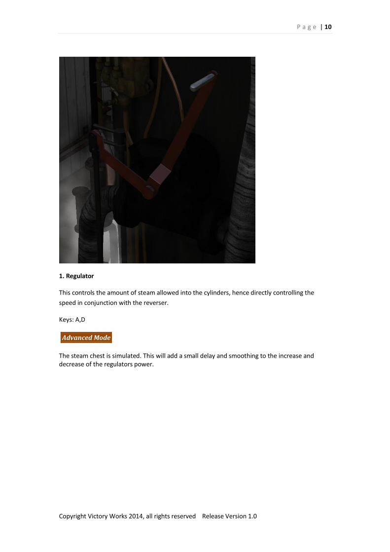
1. Regulator
This controls the amount of steam allowed into the cylinders, hence directly controlling the
speed in conjunction with the reverser.
Keys: A,D
Advanced Mode
The steam chest is simulated. This will add a small delay and smoothing to the increase and decrease of the regulators power.
P a g e | 11
Copyright Victory Works 2014, all rights reserved Release Version 1.0
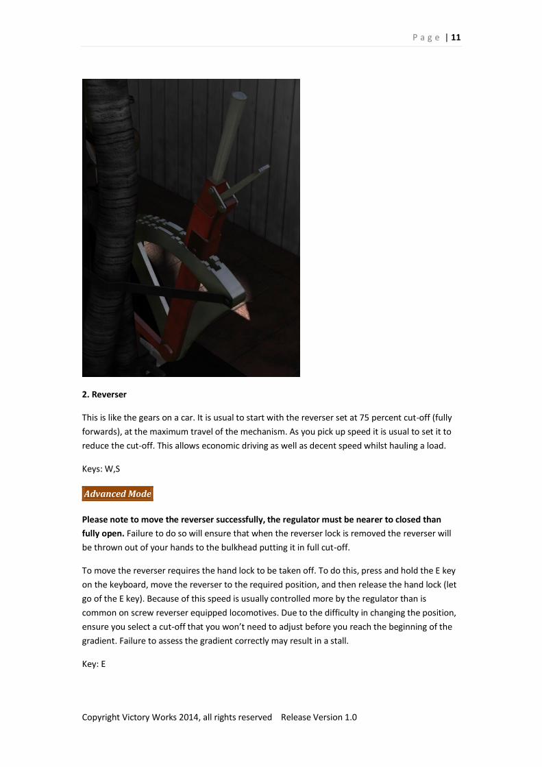
2. Reverser
This is like the gears on a car. It is usual to start with the reverser set at 75 percent cut-off (fully
forwards), at the maximum travel of the mechanism. As you pick up speed it is usual to set it to
reduce the cut-off. This allows economic driving as well as decent speed whilst hauling a load.
Keys: W,S
Advanced Mode
Please note to move the reverser successfully, the regulator must be nearer to closed than
fully open. Failure to do so will ensure that when the reverser lock is removed the reverser will
be thrown out of your hands to the bulkhead putting it in full cut-off.
To move the reverser requires the hand lock to be taken off. To do this, press and hold the E key
on the keyboard, move the reverser to the required position, and then release the hand lock (let
go of the E key). Because of this speed is usually controlled more by the regulator than is
common on screw reverser equipped locomotives. Due to the difficulty in changing the position,
ensure you select a cut-off that you won’t need to adjust before you reach the beginning of the
gradient. Failure to assess the gradient correctly may result in a stall.
Key: E

P a g e | 12
Copyright Victory Works 2014, all rights reserved Release Version 1.0
3. Cylinder Cocks
Advanced Mode
Never move away from more than a short standing start without ensuring that these are open. When a locomotive sits static for any amount of time, water condensation builds up in the cylinders. Thus when the piston is in motion, and because water does not compress, the cylinder will explode. The cylinder cocks are designed to expel this condensed water and should be opened for at least 4 turns of the locomotive wheels when the locomotive sets off after being stationary for some time. If you own the GWR 56xx DLC, this version of the cylinder cocks condensation has a longer delay
before starting and is more forgiving. You will need to clear them at the start of a scenario (the
assumption that you’ve been stationary a while) and then on long stops of more than 2 minutes.
Key: C
P a g e | 13
Copyright Victory Works 2014, all rights reserved Release Version 1.0
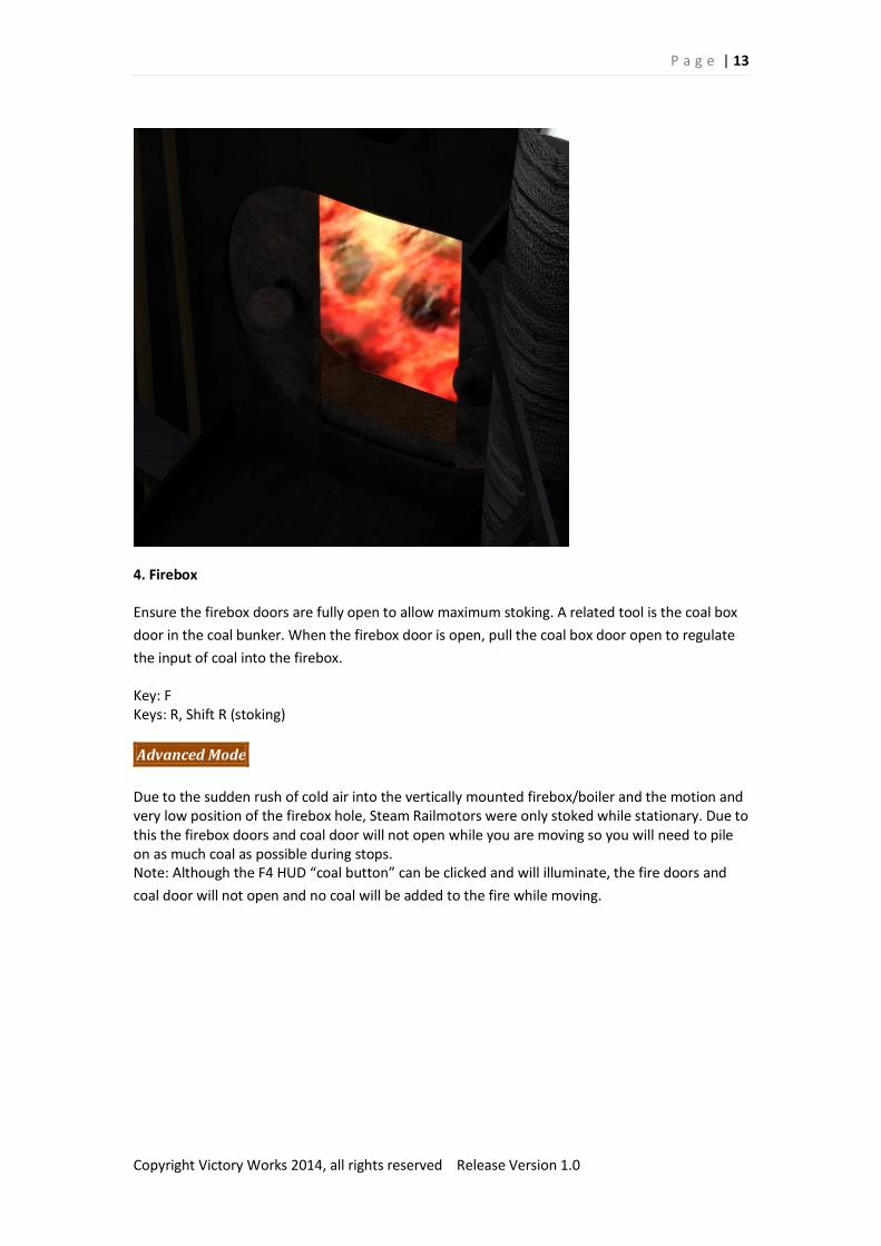
4. Firebox
Ensure the firebox doors are fully open to allow maximum stoking. A related tool is the coal box
door in the coal bunker. When the firebox door is open, pull the coal box door open to regulate
the input of coal into the firebox.
Key: F Keys: R, Shift R (stoking)
Advanced Mode
Due to the sudden rush of cold air into the vertically mounted firebox/boiler and the motion and very low position of the firebox hole, Steam Railmotors were only stoked while stationary. Due to this the firebox doors and coal door will not open while you are moving so you will need to pile on as much coal as possible during stops. Note: Although the F4 HUD “coal button” can be clicked and will illuminate, the fire doors and
coal door will not open and no coal will be added to the fire while moving.
P a g e | 14
Copyright Victory Works 2014, all rights reserved Release Version 1.0
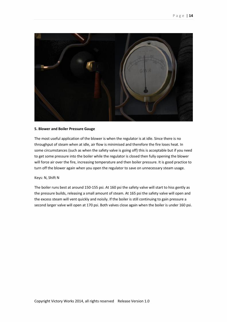
5. Blower and Boiler Pressure Gauge
The most useful application of the blower is when the regulator is at idle. Since there is no
throughput of steam when at idle, air flow is minimised and therefore the fire loses heat. In
some circumstances (such as when the safety valve is going off) this is acceptable but if you need
to get some pressure into the boiler while the regulator is closed then fully opening the blower
will force air over the fire, increasing temperature and then boiler pressure. It is good practice to
turn off the blower again when you open the regulator to save on unnecessary steam usage.
Keys: N, Shift N
The boiler runs best at around 150-155 psi. At 160 psi the safety valve will start to hiss gently as
the pressure builds, releasing a small amount of steam. At 165 psi the safety valve will open and
the excess steam will vent quickly and noisily. If the boiler is still continuing to gain pressure a
second larger valve will open at 170 psi. Both valves close again when the boiler is under 160 psi.
P a g e | 15
Copyright Victory Works 2014, all rights reserved Release Version 1.0
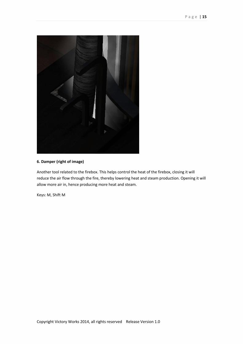
6. Damper (right of image)
Another tool related to the firebox. This helps control the heat of the firebox, closing it will
reduce the air flow through the fire, thereby lowering heat and steam production. Opening it will
allow more air in, hence producing more heat and steam.
Keys: M, Shift M
P a g e | 16
Copyright Victory Works 2014, all rights reserved Release Version 1.0
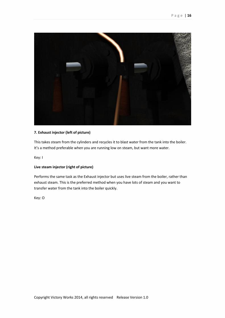
7. Exhaust injector (left of picture)
This takes steam from the cylinders and recycles it to blast water from the tank into the boiler.
It’s a method preferable when you are running low on steam, but want more water.
Key: I
Live steam injector (right of picture)
Performs the same task as the Exhaust injector but uses live steam from the boiler, rather than
exhaust steam. This is the preferred method when you have lots of steam and you want to
transfer water from the tank into the boiler quickly.
Key: O
P a g e | 17
Copyright Victory Works 2014, all rights reserved Release Version 1.0
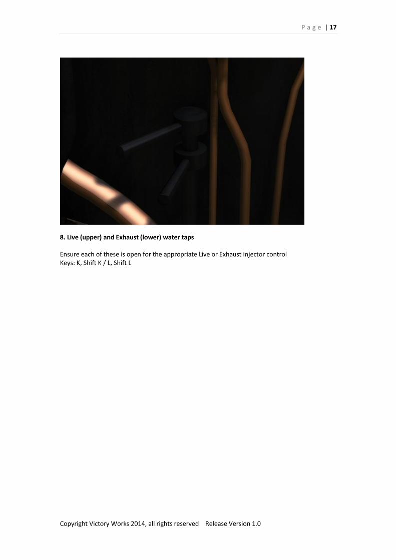
8. Live (upper) and Exhaust (lower) water taps
Ensure each of these is open for the appropriate Live or Exhaust injector control Keys: K, Shift K / L, Shift L

P a g e | 18
Copyright Victory Works 2014, all rights reserved Release Version 1.0
9. Boiler Gauge Glass
A pipe attached to the boiler leading to a strong glass tube indicating the level of water that is
currently in the boiler. If this reaches the bottom then the fusible plugs will melt and relieve the
boiler pressure whilst providing a warning to the locomotive crew.
Advanced Mode
Overfilling the boiler (past 100%) at high pressure can force water into the cylinders and cause
the same problems as having condensed water from standing still. If you overfill the boiler open
the cylinder cocks immediately and leave them open until the water level in the glass drops
below full.
P a g e | 19
Copyright Victory Works 2014, all rights reserved Release Version 1.0
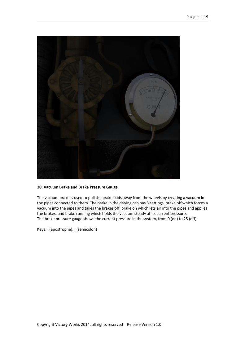
10. Vacuum Brake and Brake Pressure Gauge
The vacuum brake is used to pull the brake pads away from the wheels by creating a vacuum in the pipes connected to them. The brake in the driving cab has 3 settings, brake off which forces a vacuum into the pipes and takes the brakes off, brake on which lets air into the pipes and applies the brakes, and brake running which holds the vacuum steady at its current pressure. The brake pressure gauge shows the current pressure in the system, from 0 (on) to 25 (off). Keys: ‘ (apostrophe), ; (semicolon)

P a g e | 20
Copyright Victory Works 2014, all rights reserved Release Version 1.0
11. Sander (left of image)
The sander assists in starting without slipping and also halts slips when ascending hills covered
with leaves or light snow.
Key: X, Shift X
P a g e | 21
Copyright Victory Works 2014, all rights reserved Release Version 1.0
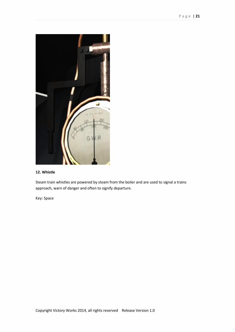
12. Whistle
Steam train whistles are powered by steam from the boiler and are used to signal a trains
approach, warn of danger and often to signify departure.
Key: Space

P a g e | 22
Copyright Victory Works 2014, all rights reserved Release Version 1.0
13. Handbrake
A hand operated screw that applies the brakes to the power bogie without the need to release
the vacuum in the brake pipes. Unusually mounted in the coal bins at the front of the cab, in
reality these were rarely used on railmotors with the vacuum brake being sufficient.
Key: /
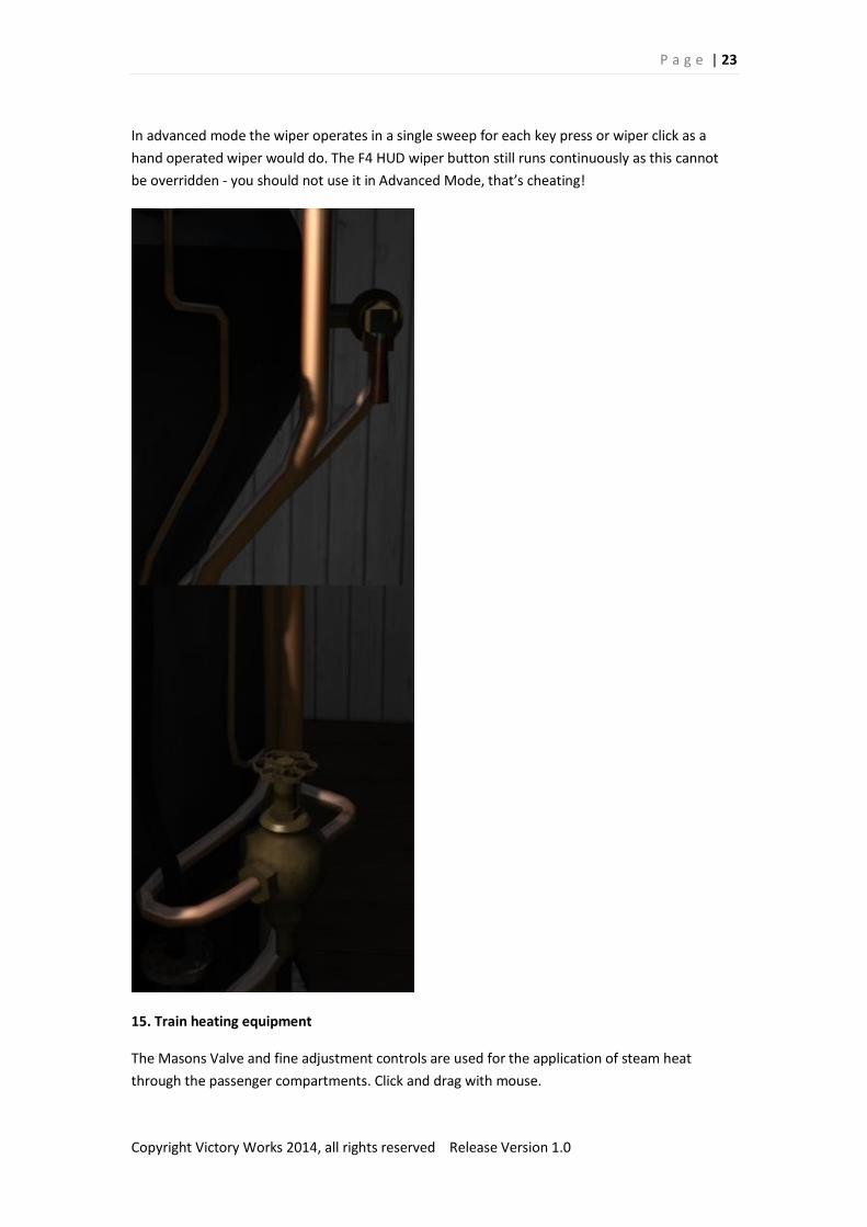
14. Wiper
Above the driving window (left) is a hand operated wiper. This can be used to clear rain, snow
and dirt directly in the driver’s view.
Key: V
Advanced Mode
P a g e | 23
Copyright Victory Works 2014, all rights reserved Release Version 1.0
In advanced mode the wiper operates in a single sweep for each key press or wiper click as a
hand operated wiper would do. The F4 HUD wiper button still runs continuously as this cannot
be overridden - you should not use it in Advanced Mode, that’s cheating!
15. Train heating equipment
The Masons Valve and fine adjustment controls are used for the application of steam heat
through the passenger compartments. Click and drag with mouse.

P a g e | 24
Copyright Victory Works 2014, all rights reserved Release Version 1.0
16. Ventilation
Working in the cab of any steam locomotive is hot work. To aid in the comfort of the crew you
can open any windows, doors or the roof panel. Click and drag with mouse.
17. Lights
The lights in the railmotor have 3 settings: off, lamps and passenger area on, cab lights on. Sometimes when driving at night when the lamps are required to be lit it is necessary, due to glare on the windows, to have the cab lamps turned off. The lamps will show clear (front) or red (back) based on the current cab being used.
Key: H, Shift H
P a g e | 25
Copyright Victory Works 2014, all rights reserved Release Version 1.0
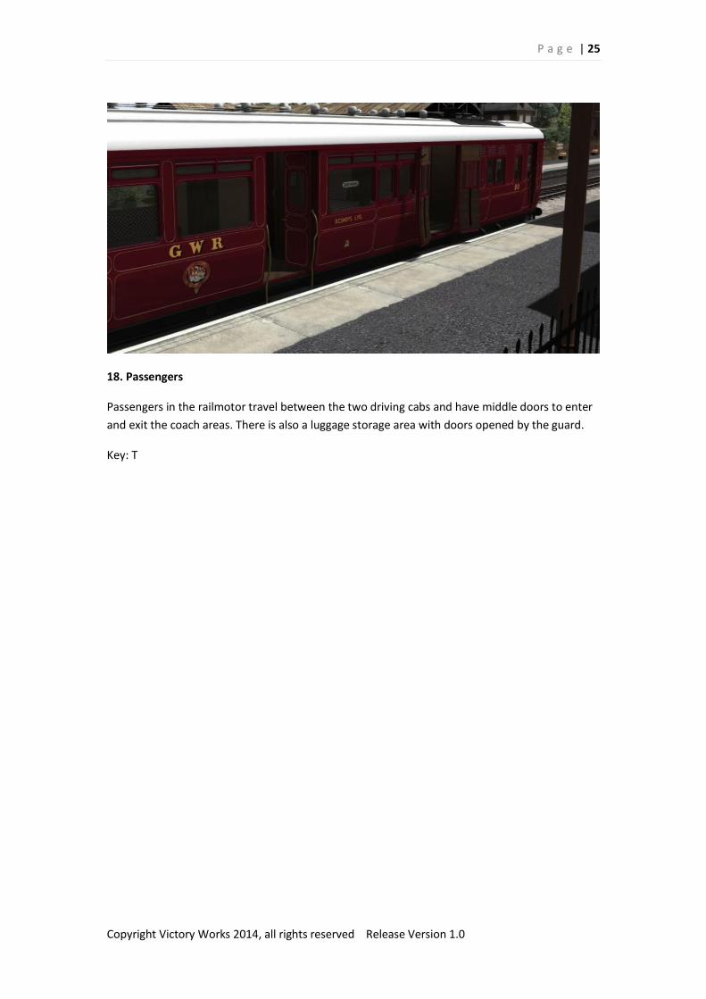
18. Passengers
Passengers in the railmotor travel between the two driving cabs and have middle doors to enter
and exit the coach areas. There is also a luggage storage area with doors opened by the guard.
Key: T
P a g e | 26
Copyright Victory Works 2014, all rights reserved Release Version 1.0
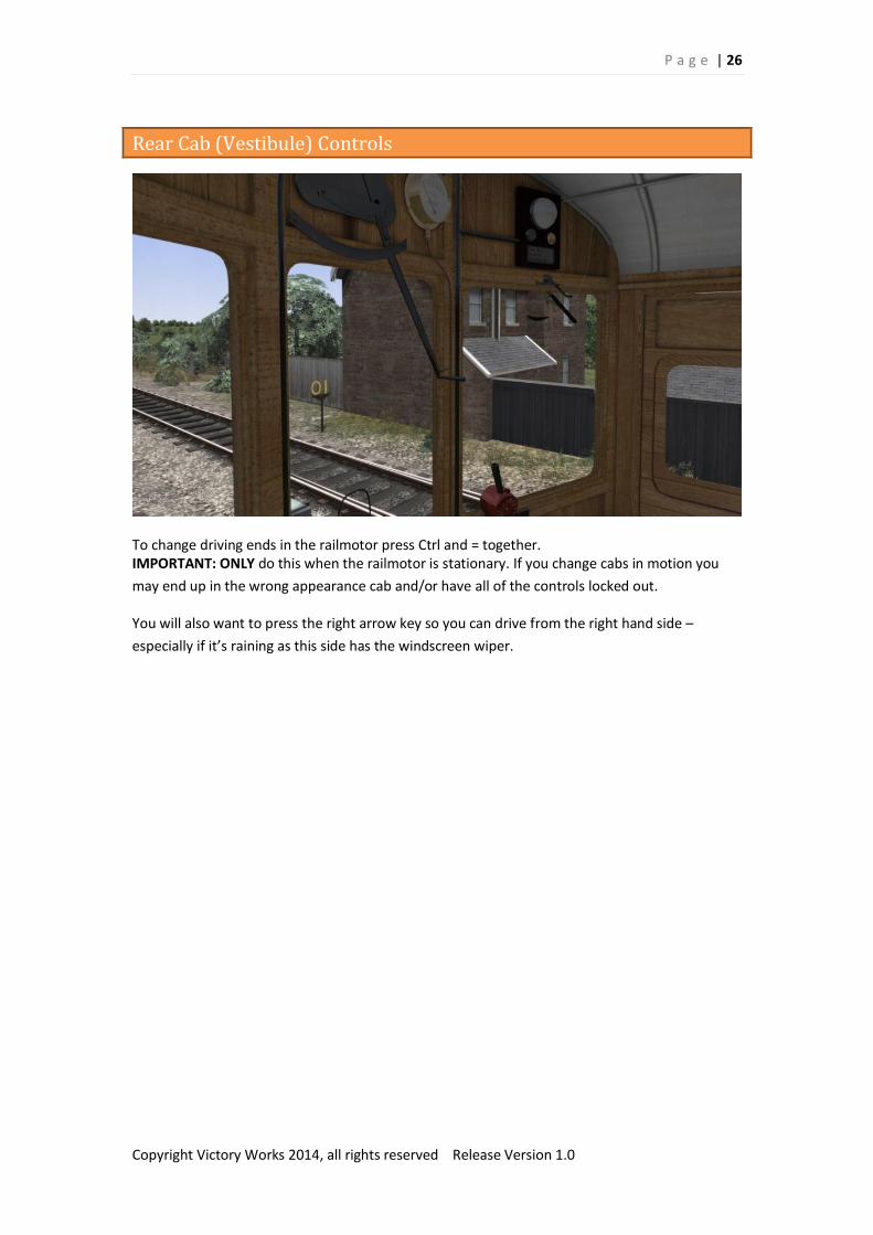
Rear Cab (Vestibule) Controls
To change driving ends in the railmotor press Ctrl and = together. IMPORTANT: ONLY do this when the railmotor is stationary. If you change cabs in motion you
may end up in the wrong appearance cab and/or have all of the controls locked out.
You will also want to press the right arrow key so you can drive from the right hand side –
especially if it’s raining as this side has the windscreen wiper.
P a g e | 27
Copyright Victory Works 2014, all rights reserved Release Version 1.0
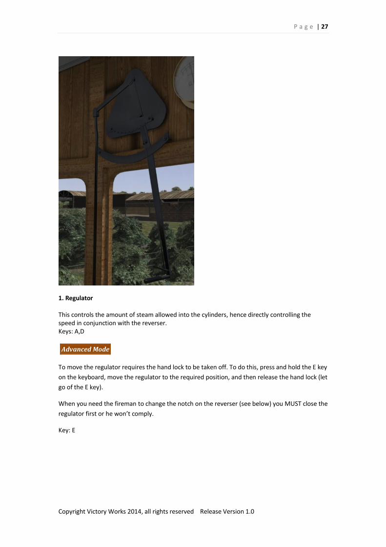
1. Regulator
This controls the amount of steam allowed into the cylinders, hence directly controlling the speed in conjunction with the reverser. Keys: A,D
Advanced Mode
To move the regulator requires the hand lock to be taken off. To do this, press and hold the E key
on the keyboard, move the regulator to the required position, and then release the hand lock (let
go of the E key).
When you need the fireman to change the notch on the reverser (see below) you MUST close the
regulator first or he won’t comply.
Key: E
P a g e | 28
Copyright Victory Works 2014, all rights reserved Release Version 1.0
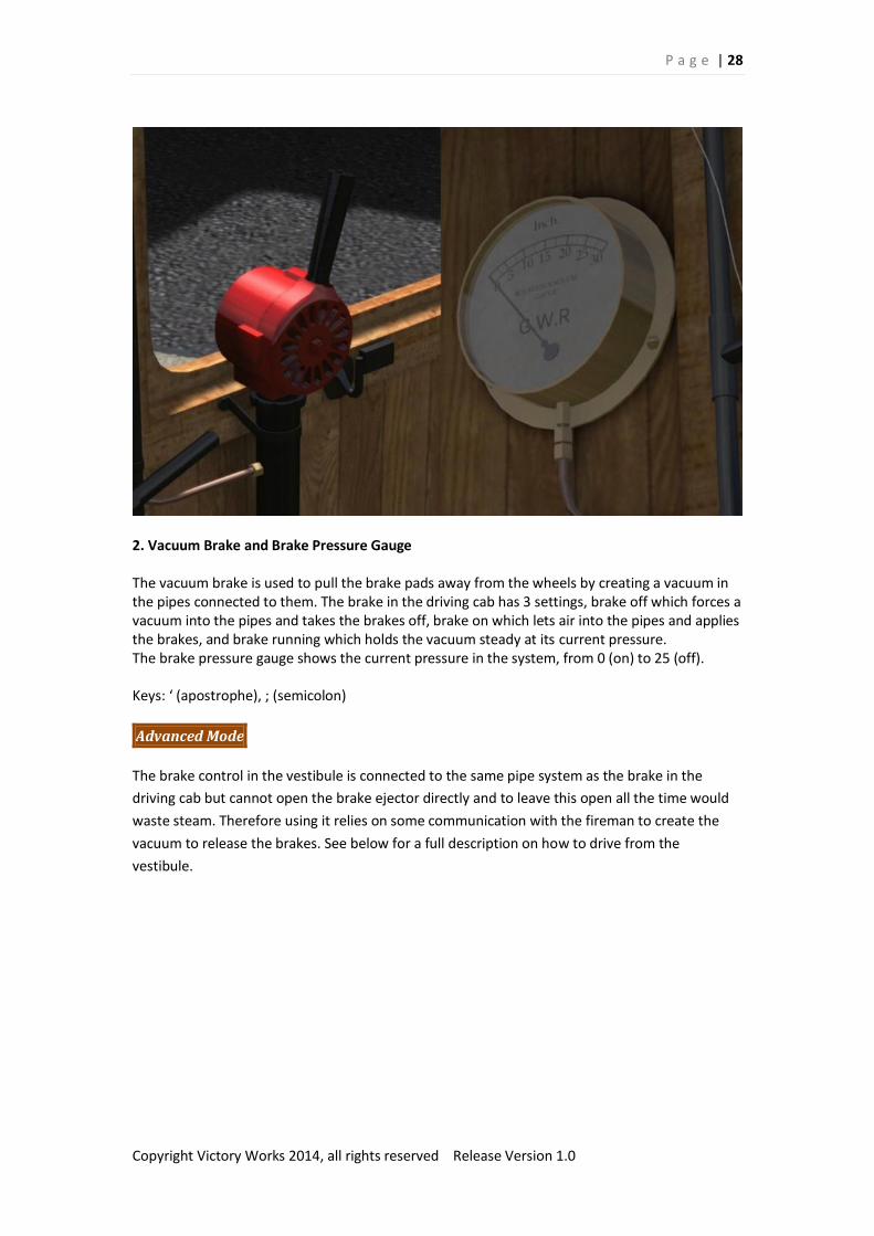
2. Vacuum Brake and Brake Pressure Gauge
The vacuum brake is used to pull the brake pads away from the wheels by creating a vacuum in the pipes connected to them. The brake in the driving cab has 3 settings, brake off which forces a vacuum into the pipes and takes the brakes off, brake on which lets air into the pipes and applies the brakes, and brake running which holds the vacuum steady at its current pressure. The brake pressure gauge shows the current pressure in the system, from 0 (on) to 25 (off). Keys: ‘ (apostrophe), ; (semicolon)
Advanced Mode
The brake control in the vestibule is connected to the same pipe system as the brake in the
driving cab but cannot open the brake ejector directly and to leave this open all the time would
waste steam. Therefore using it relies on some communication with the fireman to create the
vacuum to release the brakes. See below for a full description on how to drive from the
vestibule.

P a g e | 29
Copyright Victory Works 2014, all rights reserved Release Version 1.0
3. Sander
The sander assists in starting without slipping and also halts slips when ascending hills covered
with leaves or light snow.
Key: X, Shift X

P a g e | 30
Copyright Victory Works 2014, all rights reserved Release Version 1.0
4. Handbrake
A hand operated screw that applies the brakes to the power bogie without the need to release
the vacuum in the brake pipes. In reality these are rarely used on Railmotors with the vacuum
brake being sufficient.
Key: /
P a g e | 31
Copyright Victory Works 2014, all rights reserved Release Version 1.0
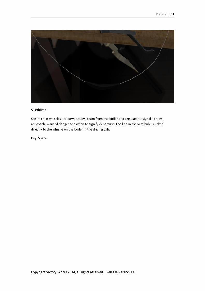
5. Whistle
Steam train whistles are powered by steam from the boiler and are used to signal a trains
approach, warn of danger and often to signify departure. The line in the vestibule is linked
directly to the whistle on the boiler in the driving cab.
Key: Space
P a g e | 32
Copyright Victory Works 2014, all rights reserved Release Version 1.0
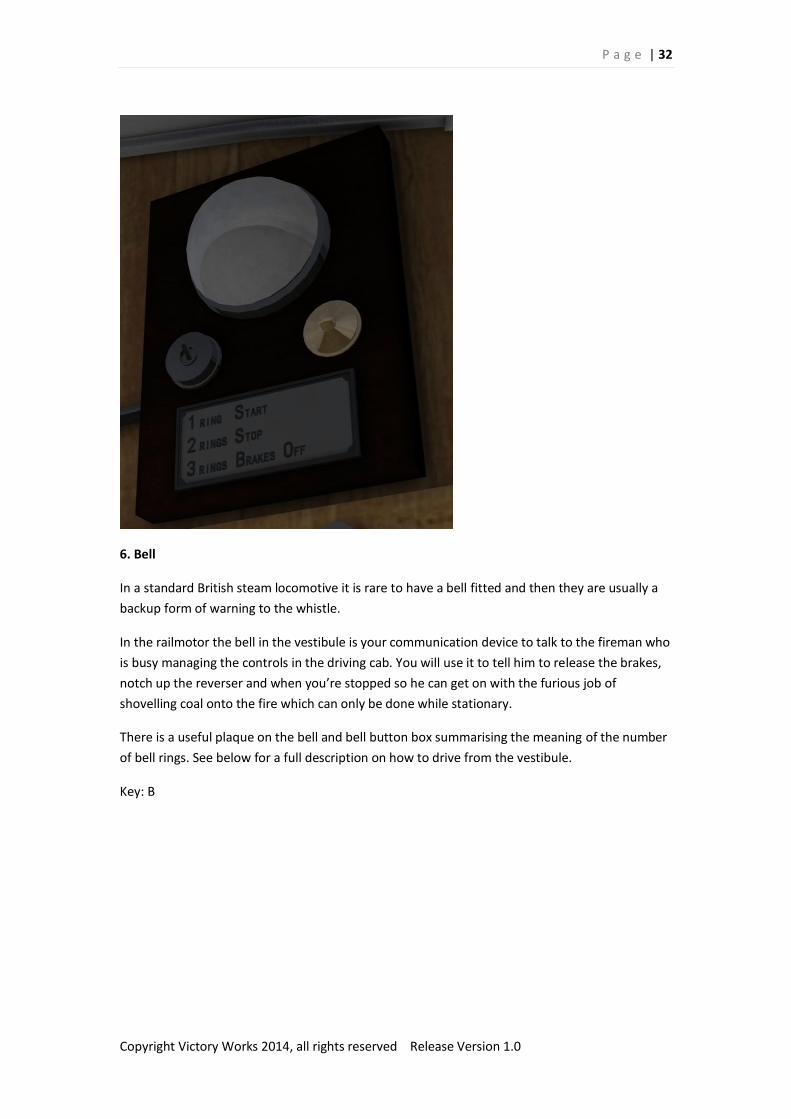
6. Bell
In a standard British steam locomotive it is rare to have a bell fitted and then they are usually a
backup form of warning to the whistle.
In the railmotor the bell in the vestibule is your communication device to talk to the fireman who
is busy managing the controls in the driving cab. You will use it to tell him to release the brakes,
notch up the reverser and when you’re stopped so he can get on with the furious job of
shovelling coal onto the fire which can only be done while stationary.
There is a useful plaque on the bell and bell button box summarising the meaning of the number
of bell rings. See below for a full description on how to drive from the vestibule.
Key: B

P a g e | 33
Copyright Victory Works 2014, all rights reserved Release Version 1.0
7. Wiper
Above the driving window (left for the front cab, right for the rear cab) is a hand operated wiper.
This can be used to clear rain, snow and dirt directly in the driver’s view.
Key: V
Advanced Mode
In advanced mode the wiper operates in a single sweep for each button press, wiper click, HUD
wiper button click. It does not move continuously. Well, it is hand operated!

P a g e | 34
Copyright Victory Works 2014, all rights reserved Release Version 1.0
8. Ventilation
Although far from the hot firebox and boiler you can still open the windows and doors of the
vestibule for ventilation. Click and drag with mouse.

P a g e | 35
Copyright Victory Works 2014, all rights reserved Release Version 1.0
Vestibule Driving in Advanced Mode
Advanced Mode ONLY
In simple and standard driving modes the vestibule is just another cab, but at the back.
In advanced mode you can have the full experience of being separated from your fireman and a
bulk of your controls and being expected to talk with him via a series of bell rings.
In the vestibule the usual tasks of notching up (moving the reverser as you gain and lose speed)
and opening and closing the cylinder cocks are performed by the fireman.
In Train Simulator terms, assuming you are not using the auto-fireman, then the jobs of using the
blower, adding coal to the fire and filling up the boiler are also taken away from you as if the
fireman in the cab is now performing them.
In addition you will need to request the fireman to create the vacuum to release the brakes.
All of this is performed either by the fireman’s own intelligence (cylinder cocks, coaling, watering
and blower) or by communicating with him using the bell above the vestibule right hand window
– the one with the wiper above it; this would be the usual position for the vestibule driver to
stand.
P a g e | 36
Copyright Victory Works 2014, all rights reserved Release Version 1.0
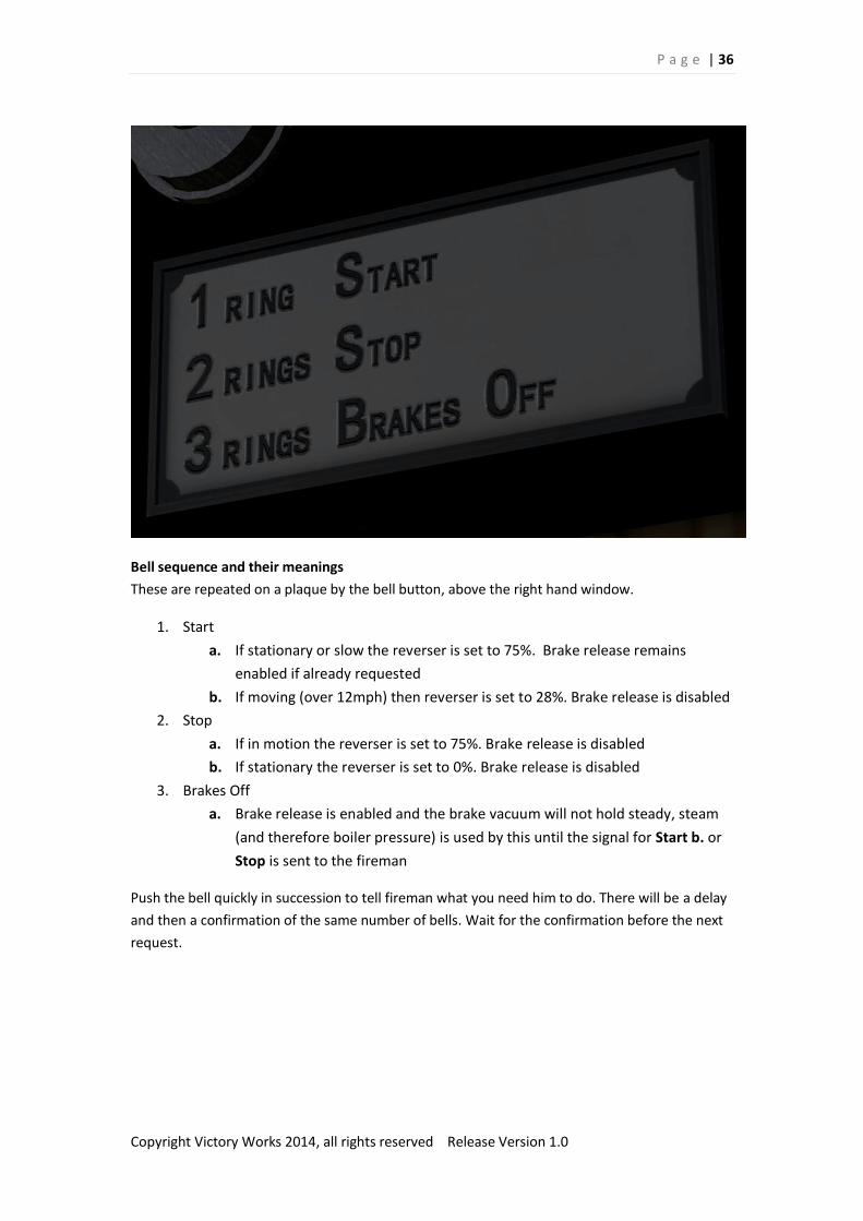
Bell sequence and their meanings
These are repeated on a plaque by the bell button, above the right hand window.
1. Start
a. If stationary or slow the reverser is set to 75%. Brake release remains
enabled if already requested
b. If moving (over 12mph) then reverser is set to 28%. Brake release is disabled
2. Stop
a. If in motion the reverser is set to 75%. Brake release is disabled
b. If stationary the reverser is set to 0%. Brake release is disabled
3. Brakes Off
a. Brake release is enabled and the brake vacuum will not hold steady, steam
(and therefore boiler pressure) is used by this until the signal for Start b. or
Stop is sent to the fireman
Push the bell quickly in succession to tell fireman what you need him to do. There will be a delay
and then a confirmation of the same number of bells. Wait for the confirmation before the next
request.
P a g e | 37
Copyright Victory Works 2014, all rights reserved Release Version 1.0
Driving procedure from the vestibule
Ready to leave
1 bell to get reverser to 75%
3 bells to release the brake
Move vestibule brake to the far right to release
Open regulator as brakes release
Once the brake vacuum is at 25 inches, move the brake back to central position
When at speed (over 12mph)
Close the regulator to stop the fireman getting injured
1 bell to get reverser to 28%
Open the regulator
Slowing for stop
2 bells to set reverser to 75% for finer control of approach
Important: At this point the brake release is not available, so any brake you apply
will remain on until you stop or request another brake release from the fireman
(which if repeated is sure to make him angry!). Therefore be frugal in braking,
measure the distance to stop against your slowing speed and apply the brake
accordingly. Stop, go, stop, go braking is not a part of the proper driving of any
steam locomotive.
When Stopped
2 bells to set reverser to 0%
Important: This tells the fireman that you are stationary for a while so he can tend
the fire if required. He will stop when it is back up to size or he receives 1 bell for
start.
P a g e | 38
Copyright Victory Works 2014, all rights reserved Release Version 1.0
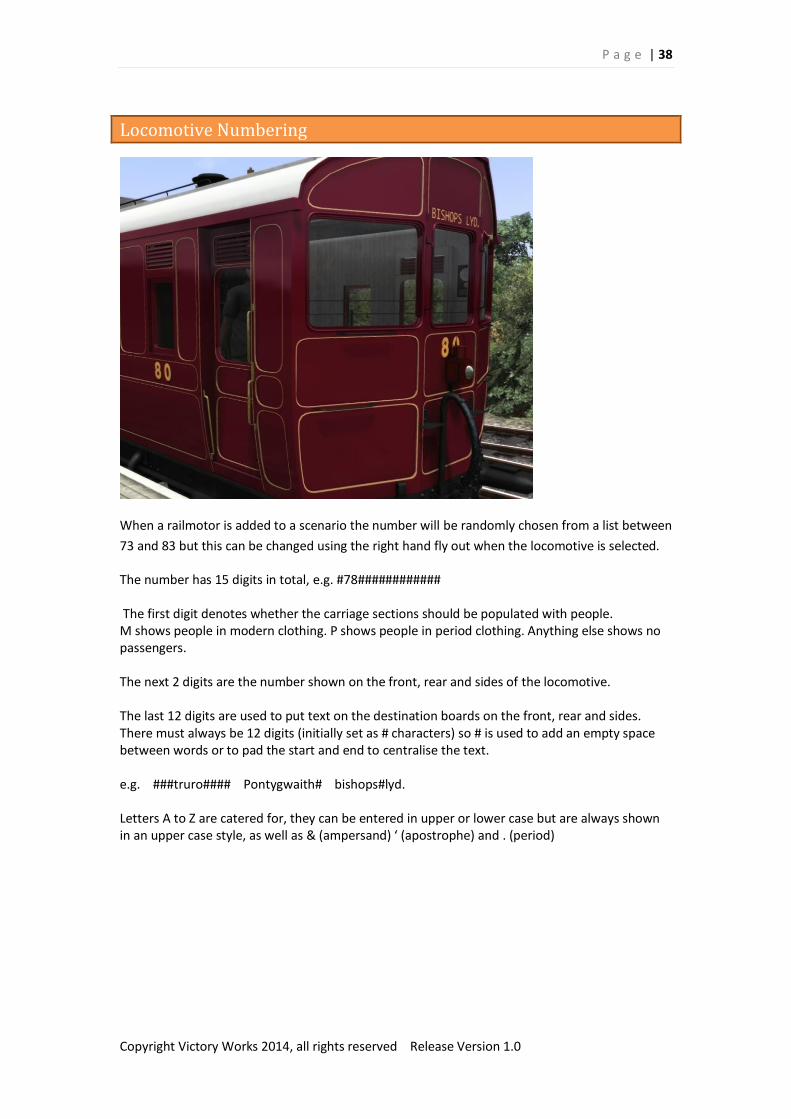
Locomotive Numbering
When a railmotor is added to a scenario the number will be randomly chosen from a list between
73 and 83 but this can be changed using the right hand fly out when the locomotive is selected.
The number has 15 digits in total, e.g. #78############
The first digit denotes whether the carriage sections should be populated with people. M shows people in modern clothing. P shows people in period clothing. Anything else shows no passengers. The next 2 digits are the number shown on the front, rear and sides of the locomotive. The last 12 digits are used to put text on the destination boards on the front, rear and sides. There must always be 12 digits (initially set as # characters) so # is used to add an empty space between words or to pad the start and end to centralise the text. e.g. ###truro#### Pontygwaith# bishops#lyd. Letters A to Z are catered for, they can be entered in upper or lower case but are always shown in an upper case style, as well as & (ampersand) ‘ (apostrophe) and . (period)

P a g e | 39
Copyright Victory Works 2014, all rights reserved Release Version 1.0
Ground Platforms and Scenario Objects
The Railmotor has many unusual features, one of which is the step arrangement at the passenger
doors. These were operated by the guard using a lever inside the porch when the locomotive
stopped at ground level platforms. These were added to branch lines when a quick and cheap
pick up/drop off stop was required rather than a full station with raised platforms.
The steps on this model are fully functional however they require the platforms to be set up in
the simulator and a special Ground Platform Marker added at each end of the platform to tell the
railmotor when it is next to them.
Unfortunately at the current time although you can add platform markers and static scenery to
scenarios, you can’t add lofted items and this means you can’t add the passenger spawning
platform areas to a scenario. Due to this the ground platforms need to be added to the route and
can’t be added on an ad hoc basis to a scenario.
The special Ground Platform Marker can be added directly to the route or just to scenarios that
feature the railmotor – if you do the latter then you will need to be add it to every ground
platform on every scenario that requires a pick up there.
Train Simulator 2014 introduced a new feature to the build menu which allows you to clone a
route very easily. It also allows you to upload these cloned and modified routes to the Steam
Workshop so the intention is to create some specific railmotor versions of certain routes, add
some ground platforms and upload these so they can be downloaded for free.
You can also do this yourself for any route, or include ground platforms in new routes you are
building.

P a g e | 40
Copyright Victory Works 2014, all rights reserved Release Version 1.0
Once you have added some scenery to look like a ground platform and laid down a platform loft
(either an invisible one or hide the platform just under the ground) and platform marker you
have all you need on the route.
To add the marker, tick the VictoryWorks /GWRSteamRailmotor assets in the object filter. Under
the Miscellaneous tab find the asset called Ground Platform Marker (for Steam Railmotor) and
place it in the middle of the track by the platform. Place the first link past one end of the
platform and the second link past the other end. Make sure it is longer than the area where the
railmotor will stop. Once these are placed, drop the small orange/blue marker below the ground
so it can’t be seen.
Important: Make sure that the links are not placed dividing the links of a signal as this may cause
odd signalling problems.

P a g e | 41
Copyright Victory Works 2014, all rights reserved Release Version 1.0
Also included with the railmotor are the coal sacks and hose which are used in some of the
provided scenarios for refuelling.
You can add these into your own routes or scenarios by entering the editor and ticking the
VictoryWorks/GWRSteamRailmotor assets in the object filter. Under the Miscellaneous tab you
can then select the Coal Sacks – Refuelling Point or Hose – Refuelling Point and place them on
the route – you also need to place the attached link at the point on the track where the
locomotive needs to stop.

P a g e | 42
Copyright Victory Works 2014, all rights reserved Release Version 1.0
Acknowledgements
I would like to thank the following people for their help and encouragement during this project:
Stuart Galbraith for his work on the loco performance and constant advice, ideas
and critique
DOM107 (UKTrainSim) for his Blender exporter
Paul Godber for his generous advice
Chris Barnes for allowing me to use his superb smoke/steam textures
“The Secret Forum” for their critique and constant encouragement
Matt Peddlesden
Everyone at Dovetail Games
My wife for all her support in this new endeavour, and my father for instilling in me
a love of steam trains from an early age