Embed Size (px)
Citation preview

GXF Format revision 3.0 Draft 9.1
12 April, 1999 GXF .. i
GXF
Grid eXchange File
Revision 3.0draft 9.1
12 April, 1999GEOSOFT Inc.
Suite 800, 85 Richmond St. W.Toronto, ON, Canada
Tel. 416 369-0111Fax. 416 369-9599www.geosoft.com
GXF Format revision 3.0 Draft 9.1
12 April, 1999 GXF .. i
CONTENTS
1. INTRODUCTION................................................................................................................ 1
MAP PROJECTIONS ................................................................................................................................1
2. GRID DESCRIPTION......................................................................................................... 2
3. GXF FORMAT..................................................................................................................... 3
4. GXF OBJECT DEFINITIONS ........................................................................................... 5
#DUMMY.............................................................................................................................................5#GRID...................................................................................................................................................5
Compression.....................................................................................................................................6#GTYPE ...............................................................................................................................................7#MAP_PROJECTION..........................................................................................................................8#MAP_DATUM_TRANSFORM.......................................................................................................11#POINTS ............................................................................................................................................12#PTSEPARATION.............................................................................................................................12#ROTATION......................................................................................................................................13#ROWS...............................................................................................................................................13#RWSEPARATION ...........................................................................................................................13#SENSE ..............................................................................................................................................14#TITLE ...............................................................................................................................................15#TRANSFORM..................................................................................................................................15#UNIT_LENGTH...............................................................................................................................16#XORIGIN..........................................................................................................................................16#YORIGIN..........................................................................................................................................17#ZMAXIMUM ...................................................................................................................................17#ZMINIMUM.....................................................................................................................................18##XXXX...............................................................................................................................................18
5. NAME TABLES.................................................................................................................. 19
TABLE 1 PROJECTION TRANSFORMATION METHODS ........................................................................19TABLE 2 LENGTH UNITS ....................................................................................................................22
6. EXAMPLES........................................................................................................................ 23
REFERENCES ........................................................................................................................ 27
GXF Format revision 3.0 Draft 9.1
12 April, 1999 GXF .. 1
1. INTRODUCTION
GXF (Grid eXchange File) is a standard ASCII file format for exchanging gridded data amongdifferent software systems. Software that supports the GXF standard will be able to importproperly formatted GXF files and export grids in GXF format.
GXF Revision 1 was drafted by Ian MacLeod at the request of the Canadian ExplorationGeophysical Society (KEGS) of Toronto. It found significant usage in the mining andenvironment sectors. Revision 2.00 was undertaken in conjunction with the Australian Societyof Exploration Geophysicists (ASEG) who adopted it as their standard. The main advance ofRevision 2 over Revision 1 was the addition of data compression through the use of base-90numbers and simple repeat value compression. These extensions made GXF more practicalfor exchanging large gridded data sets. GXF Revision 2 was adopted by theGravity/Magnetics Committee of the Society of Exploration Geophysicists (SEG) inNovember 1997, with the urging that the standard be further extended to encompass theexchange of map projection information.
Map Projections
This document defines GXF-3, which implements the exchange of map projectioninformation. GXF-3 conforms to the POSC/EPSG projection data model and exploits theEPSG projection tables and the POSC naming conventions, which are based on the EPSGtables. All parameter names used to define projection information are required to usePOSC/EPSG standard names where they are known or supported. Where differences existbetween POSC and EPSG, POSC usage is adopted in GXF 3.
Although GXF-3 requires the use of POSC/EPSG names, all projection parameters must alsobe explicitly specified as part of the projection definitions. Where a particular parameter orname is not defined by POSC or EPSG, any appropriate name can be used and such namesmust begin with the “*” character. This is an important feature of GXF because it allows GXFto support grids that use projections that are not defined in POSC/EPSG. It is not uncommonfor exploration data to use obscure and even ad-hoc projections, and support for suchprojections has been a requirement in the design of GXF-3.
Wherever POSC/EPSG names are used, the actual parameter specifications defined byPOSC/EPSG can be used if supported by the GXF reader. GXF readers that do not haveaccess to EPSG/POSC tables will still have all parameters available in GXF. This allows aGXF reader to resolve any map projection as may be required or supported by the readerapplication.
The full definition of EPSG/POSC parameter values is beyond the scope of this document.Developers of GXF readers and writers are referred to the EPSG and POSC references noted atthe end of this document.
GXF Format revision 3.0 Draft 9.1
12 April, 1999 GXF .. 2
2. GRID DESCRIPTION
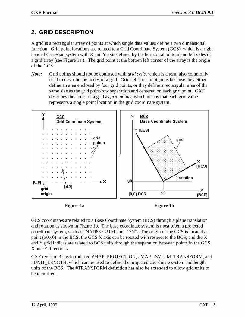
A grid is a rectangular array of points at which single data values define a two dimensionalfunction. Grid point locations are related to a Grid Coordinate System (GCS), which is a righthanded Cartesian system with X and Y axis defined by the horizontal bottom and left sides ofa grid array (see Figure 1a.). The grid point at the bottom left corner of the array is the originof the GCS.
Note: Grid points should not be confused with grid cells, which is a term also commonlyused to describe the nodes of a grid. Grid cells are ambiguous because they eitherdefine an area enclosed by four grid points, or they define a rectangular area of thesame size as the grid point/row separation and centered on each grid point. GXFdescribes the nodes of a grid as grid points, which means that each grid valuerepresents a single point location in the grid coordinate system.
Figure 1a Figure 1b
GCS coordinates are related to a Base Coordinate System (BCS) through a plane translationand rotation as shown in Figure 1b. The base coordinate system is most often a projectedcoordinate system, such as “NAD83 / UTM zone 17N”. The origin of the GCS is located atpoint (x0,y0) in the BCS; the GCS X axis can be rotated with respect to the BCS; and the Xand Y grid indices are related to BCS units through the separation between points in the GCSX and Y directions.
GXF revision 3 has introduced #MAP_PROJECTION, #MAP_DATUM_TRANSFORM, and#UNIT_LENGTH, which can be used to define the projected coordinate system and lengthunits of the BCS. The #TRANSFORM definition has also be extended to allow grid units tobe identified.
GXF Format revision 3.0 Draft 9.1
12 April, 1999 GXF .. 3
3. GXF FORMAT
A GXF file is an ASCII file made up of a number of labeled data objects and comments. Eachlabeled data object has a label line followed by one or more data lines. A label line isidentified by a ’#’ character in the first column followed immediately by an upper-case label.The data associated with that label are found on one or more lines that follow the label.
Any lines that are not part of a labeled data object are ignored and can be used to placecomments within a GXF file. Programs that read GXF files ignore such comment lines whilesearching for the next GXF data object.
All lines in a GXF file must be less than or equal to 80 characters in length. If the last non-white space character on a line is a ‘\’, the next line is assumed to be a continuation of thecurrent line (except for #GRID data lines). Spaces and tab characters are white spacecharacters. Note that continuation lines are a feature of GXF revision 3, and they should onlybe required for defining projection parameters that require more than 80 characters. They arenot required and cannot be used for writing grid data to the GXF (in the #GRID object). Thisallows GXF readers written for GXF revision 2 and earlier to read GXF revision 3 files.
Any name or string parameters that are part of a data object and which themselves containspaces, must be enclosed in double quotes.
Parameters on data lines may be separated by a space or comma.
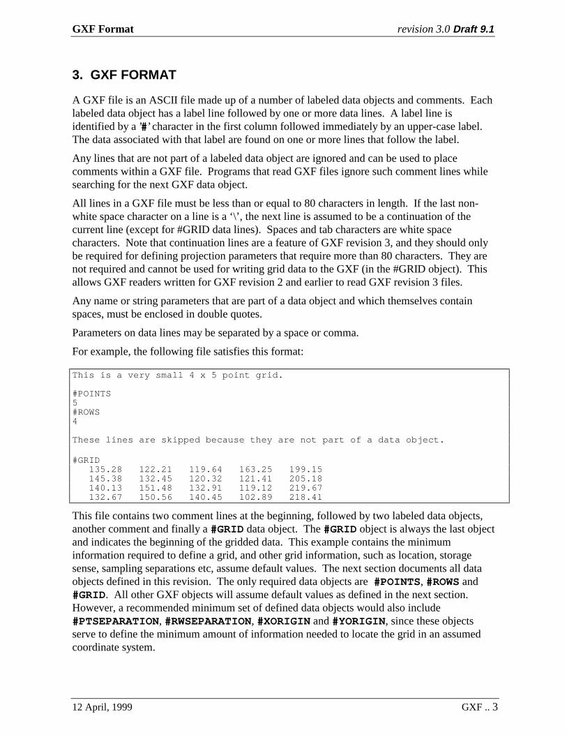
For example, the following file satisfies this format:
This is a very small 4 x 5 point grid.
#POINTS5#ROWS4
These lines are skipped because they are not part of a data object.
#GRID135.28 122.21 119.64 163.25 199.15145.38 132.45 120.32 121.41 205.18140.13 151.48 132.91 119.12 219.67132.67 150.56 140.45 102.89 218.41
This file contains two comment lines at the beginning, followed by two labeled data objects,another comment and finally a #GRID data object. The #GRID object is always the last objectand indicates the beginning of the gridded data. This example contains the minimuminformation required to define a grid, and other grid information, such as location, storagesense, sampling separations etc, assume default values. The next section documents all dataobjects defined in this revision. The only required data objects are #POINTS, #ROWS and#GRID. All other GXF objects will assume default values as defined in the next section.However, a recommended minimum set of defined data objects would also include#PTSEPARATION, #RWSEPARATION, #XORIGIN and #YORIGIN, since these objectsserve to define the minimum amount of information needed to locate the grid in an assumedcoordinate system.

GXF Format revision 3.0 Draft 9.1
12 April, 1999 GXF .. 4
We recommend that comments, which more fully document the grid data, be placed at thebeginning of a GXF file. The type of information to include in a comment section will dependon the intended data application.

GXF Format revision 3.0 Draft 9.1
12 April, 1999 GXF .. 5
4. GXF OBJECT DEFINITIONS
#DUMMY
The grid must be rectangular (every row must have the same number of points). Thedummy value defined by this object is used to define blank areas of the grid. Anygrids that include blank areas must define a dummy value. The only exceptions arecompressed grids, which have a pre-defined dummy value.
Default: no dummy value.
Example:
#DUMMY-99999.0
This defines "-99999.0" to be used to represent dummy values in the grid.
It is important to specify the dummy value exactly as it will appear in the #GRIDobject. GXF readers could read the value ’-99999’ differently than ’-99999.0’, andwould not be able to properly identify blank areas.
#GRID
The grid data is listed point by point and row by row. If the #GTYPE object isdefined and non-zero, the data is written in base-90 compressed format, otherwise,the data are written as normal base-10 numbers, with each number separated by oneor more spaces. The #GRID object and data is always the last object in a GXF file.
The first data point is at the location indicated by #SENSE, and is followed bysuccessive points in that row of grid points (either horizontal or vertical), then thepoints in the next grid row, and so on. The points in a grid row can follow on to thenext GXF line, although each new grid row must start on a new GXF line. A GXFreading program can expect #ROWS of #POINTS for a total of #ROWS times#POINTS data values.
Note that each GXF line must have no more than 80 characters, and each GXF lineshould only have as many data values as will fit on that line. Continuation charactersare not needed and cannot be used for the grid data lines.
Default: none, must be included as the last object in a GXF file.

GXF Format revision 3.0 Draft 9.1
12 April, 1999 GXF .. 6
Example:
A 5 by 4 point grid in uncompressed format:
#GRID 135.28 122.21 119.64 163.25 199.15 145.38 132.45 120.32 121.41 205.18 140.13 151.48 132.91 119.12 219.67 132.67 150.56 140.45 102.89 218.41
or:
#GRID 135.28 122.21 119.64 163.25 199.15 145.38 132.45 120.32 121.41 205.18 140.13 151.48 132.91 119.12 219.67 132.67 150.56 140.45 102.89 218.41
Compression
If the #GTYPE object has been defined (and is > 0), each grid point is expressed as abase-90 integer of a fixed length specified by #GTYPE. If the #GTYPE object is notpresent before the #GRID object, the grid data is assumed to be uncompressed.Although a compressed GXF file is less readable, the advantage of a smaller file canbe important for large grids.
Using the base-90 numbering system, a grid data value (Z) is first converted to awhole number (positive integer) using the SCALE and OFFSET defined by the#TRANSFORM object:
I90 = (Z - OFFSET) / SCALE
where
I90 whole number used to represent grid values in the GXF file.Z real grid value
OFFSET specified by #TRANSFORMSCALE specified by #TRANSFORM
The offset and scale are chosen to transform the original grid value to the range 0 to(90P-1), where P is the number of base-90 digits defined by #GTYPE.
Base-90 digits use ASCII characters in the range 37 to 126 ("%" to "~"), with themost significant character first (just as base-10 numbers use ASCII characters 48 to57, which are characters "0" to "9"). Each grid value occupies a fixed number ofcharacters specified by the #GTYPE object and there are no spaces between values.For example, assuming 3 digit base-90 numbers (#GTYPE set to 3), the base-90number "%%%" (ASCII codes 37 37 37) is a base-10 number 0, base-90 number"%%&" (ASCII 37 37 38) is a base-10 number 1, and the base-90 number "~~~"(ASCII 126 126 126) is a base-10 number 728,999 (903 - 1).

GXF Format revision 3.0 Draft 9.1
12 April, 1999 GXF .. 7
Grid dummy values are always expressed as "!" characters (ASCII 33), so a 3 digitdummy value would be "!!!".
Series of consecutive grid values can be further compressed using a repeat code. Therepeat character is " (ASCII 34) and must be duplicated #GTYPE times, to befollowed by the number of times to repeat the following base-90 number. Forexample, assuming a #GTYPE value of 3, a repeat count has the following format:
"""NNNxxx
where """ indicates the start of a repeat sequenceNNN is a base-90 integer that specifies the number of times to repeat
the following valuexxx is the base-90 grid value to be repeated, or "!!!" if the value is
a dummy
The 3 and 2 digit repeat sequences to represent 10 dummy values in a row would be:
3-digit: """%%/!!!2-digit: ""%/!!
Any lines within a compressed data object that begin with a "$" character in column1 are skipped and can be used to add comments to the compressed data. Commentsmight be used to indicate the grid row number, for example.
Just as with uncompressed data, values in a grid row can follow to the next data lineand new grid rows must start on a new line. Each row of the GXF file must have nomore than 80 characters. If more than one line is required for a grid row, the linebreak must be at an integer multiple of #GTYPE. Three item repeat codes may alsobe split between lines.
Example:
Following is the same 5 by 4 point grid as in the previous example, but incompressed format using a precision of 3 characters per grid value. Note that#GTYPE is required, and #TRANSFORM would be required if the original datawere not whole numbers in the range 0 to 728,999.
#TRANSFORM0.005,-3.835000000000000#GTYPE 3#GRID(L2(/.()H)0@*&,(bZ(Er(*v(-B*3P(Vx(p2(Ft((:*Sb(FD(n.(W^’^4*Pt
Additional compressed examples are shown in the EXAMPLES section.
#GTYPE
This object is used to specify the number of digits to use for base-90 compression ofthe grid data. If not specified, or if 0 digits are specified, base-90 compression of the

GXF Format revision 3.0 Draft 9.1
12 April, 1999 GXF .. 8
data is not used. Refer to the description of base-90 compression under the #GRIDlabel definition. The precision obtained by different numbers of characters(calculated as 90 raised to the power of the #GTYPE) is as follows:
#GTYPE = 1 1 in 90, sufficient for 4-bit data#GTYPE = 2 1 in 8,100, sufficient for 8-bit data#GTYPE = 3 1 in 729,000, sufficient for 16-bit data and most 32-bit data#GTYPE = 4 1 in 65,610,000, sufficient for almost all 32-bit data#GTYPE = 5 1 in 5,904,900,000, sufficient for most data applications
Default: If #GTYPE is not present, or the number of digits is set to 0, gridcompression is not used. If present, a precision must be defined(typically between 1 and 5, with 4 recommended).
#MAP_PROJECTION
This defines the name and parameters of the map projection of the Base CoordinateSystem (BCS) of the grid, if known. The design of this object is based on theprojection system model described by POSC and EPSG, which distinguishes betweena Geographic Coordinate System and a Projected Coordinate System.
Geographic Coordinate System
This is a coordinate system that uses longitude and latitude coordinates. Itrequires the definition of a map datum, which includes an ellipsoid, a primemeridian and, optionally, a local map datum transformation that can be used tolocate the local datum relative to WGS 84. For example, the datum “NAD83”(North American Datum 1983) uses the “GRS 1980” ellipsoid, the centralmeridian is at Greenwich (0.0), and there are a number of local datumtransformations relative to WGS 84 for different parts of North America.Common Geographic Coordinate Systems of the world are listed in POSC table“geographic_coordinate_systems”, and in the GEOD_DATUM table of the EPSGGeodesy Parameters. (Refer to the EPSG and POSC information sources noted inthe References for further information.)
Projected Coordinate System
This is a Geographic Coordinate System together with a map projection systemthat is used to transform (longitude, latitude) coordinates of the GeographicCoordinate System to projected map coordinates (x,y). POSC and EPSGProjected Coordinate System names are composed by concatenating theGeographic Coordinate System (datum) name and the map projection nameseparated by “ / “ (space forward-slash space) characters.
For example, the projected coordinate system "NAD83 / UTM zone 17N" definesboth the Datum, “NAD 83”, and the projection system, “UTM zone 17N”, whichis a Transverse Mercator projection with standard defined parameters. CommonProjected Coordinate Systems of the world are listed in POSC table

GXF Format revision 3.0 Draft 9.1
12 April, 1999 GXF .. 9
“projected_coordinate_systems”, and in the HORIZ_CS table of the EPSGGeodesy Parameters.
POSC and EPSG names are case sensitive. If the POSC or EPSG name is notknown, any name may be used and the name must begin with a “*” character. Forexample, the South American Magnetic Mapping Project spherical datum is notdefined in EPSG (as of the date of this document), so it is commonly named“*SAMMP”.
Three data lines are required to define a map projection (Note: Names that includespaces must be enclosed by double quotes):
“projection name”“datum”, major_axis, eccentricity, prime_meridian“projection method”, parameters
“projection name” The unique key name or description of the projectionsystem. This should be the POSC, EPSG geographiccoordinate system (datum) name (i.e. “NAD83”) or theprojected coordinate system name (i.e. “NAD83 / UTMzone 17N”). Note that POSC and GXF will use thedatum abbreviation as defined in EPSG when it exists.
“datum” The name of the datum, which should be one of “GeodDatum Name” or “Geod Datum Abbrev” fields definedin the GEOD_DATUM table of EPSG.
Many working coordinate systems are known only bytheir ellipsoid. For such systems, a common conventionis to provide the ellipsoid name (from the ELLIPSOIDtable in EPSG) preceded by a “*” character.
major axis The ellipsoid semi-major axis in metres.
eccentricity The ellipsoid eccentricity. Eccentricity, ellipticity (alsocalled inverse flattening) and flattening are related asfollows:
flattening = 1 - (minor_axis/major_axis)ellipticity = 1/flatteningeccentricity = √( 2*flattening - flattening*flattening )minor_axis =
major_axis * √( 1 – eccentricity*eccentricity)
Eccentricity is used in GXF in order to allow sphericalellipsoids to be defined (eccentricity = 0).
prime_meridian The location of the prime meridian in degrees relative toGreenwich (negative in the Western hemisphere).
GXF Format revision 3.0 Draft 9.1
12 April, 1999 GXF .. 10
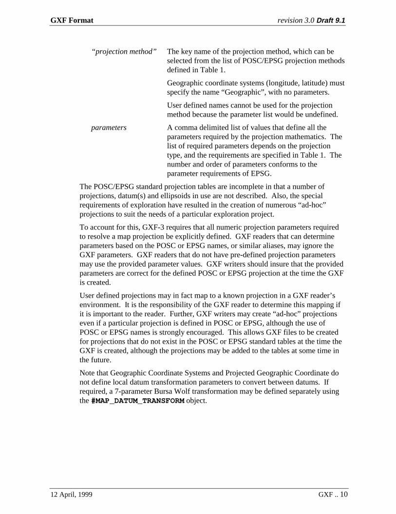
“projection method” The key name of the projection method, which can beselected from the list of POSC/EPSG projection methodsdefined in Table 1.
Geographic coordinate systems (longitude, latitude) mustspecify the name “Geographic”, with no parameters.
User defined names cannot be used for the projectionmethod because the parameter list would be undefined.
parameters A comma delimited list of values that define all theparameters required by the projection mathematics. Thelist of required parameters depends on the projectiontype, and the requirements are specified in Table 1. Thenumber and order of parameters conforms to theparameter requirements of EPSG.
The POSC/EPSG standard projection tables are incomplete in that a number ofprojections, datum(s) and ellipsoids in use are not described. Also, the specialrequirements of exploration have resulted in the creation of numerous “ad-hoc”projections to suit the needs of a particular exploration project.
To account for this, GXF-3 requires that all numeric projection parameters requiredto resolve a map projection be explicitly defined. GXF readers that can determineparameters based on the POSC or EPSG names, or similar aliases, may ignore theGXF parameters. GXF readers that do not have pre-defined projection parametersmay use the provided parameter values. GXF writers should insure that the providedparameters are correct for the defined POSC or EPSG projection at the time the GXFis created.
User defined projections may in fact map to a known projection in a GXF reader’senvironment. It is the responsibility of the GXF reader to determine this mapping ifit is important to the reader. Further, GXF writers may create “ad-hoc” projectionseven if a particular projection is defined in POSC or EPSG, although the use ofPOSC or EPSG names is strongly encouraged. This allows GXF files to be createdfor projections that do not exist in the POSC or EPSG standard tables at the time theGXF is created, although the projections may be added to the tables at some time inthe future.
Note that Geographic Coordinate Systems and Projected Geographic Coordinate donot define local datum transformation parameters to convert between datums. Ifrequired, a 7-parameter Bursa Wolf transformation may be defined separately usingthe #MAP_DATUM_TRANSFORM object.
GXF Format revision 3.0 Draft 9.1
12 April, 1999 GXF .. 11
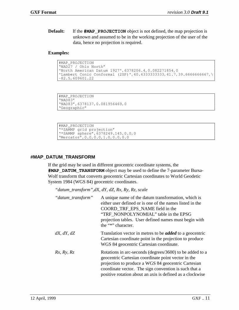
Default: If the #MAP_PROJECTION object is not defined, the map projection isunknown and assumed to be in the working projection of the user of thedata, hence no projection is required.
Examples:
#MAP_PROJECTION“NAD27 / Ohio North”"North American Datum 1927",6378206.4,0.082271854,0"Lambert Conic Conformal (2SP)",40.4333333333,41.7,39.6666666667,\-82.5,609601.22
#MAP_PROJECTION“NAD83”“NAD83”,6378137,0.081956469,0“Geographic”
#MAP_PROJECTION“*SAMMP grid projection”“*SAMMP sphere”,6378249.145,0.0,0“Mercator”,0.0,0.0,1.0,0.0,0.0
#MAP_DATUM_TRANSFORM
If the grid may be used in different geocentric coordinate systems, the#MAP_DATUM_TRANSFORM object may be used to define the 7-parameter Bursa-Wolf transform that converts geocentric Cartesian coordinates to World GeodeticSystem 1984 (WGS 84) geocentric coordinates.
“datum_transform”,dX, dY, dZ, Rx, Ry, Rz, scale
“datum_transform” A unique name of the datum transformation, which iseither user defined or is one of the names listed in theCOORD_TRF_EPS_NAME field in the“TRF_NONPOLYNOMIAL” table in the EPSGprojection tables. User defined names must begin withthe “*” character.
dX, dY, dZ Translation vector in metres to be added to a geocentricCartesian coordinate point in the projection to produceWGS 84 geocentric Cartesian coordinate.
Rx, Ry, Rz Rotations in arc-seconds (degrees/3600) to be added to ageocentric Cartesian coordinate point vector in theprojection to produce a WGS 84 geocentric Cartesiancoordinate vector. The sign convention is such that apositive rotation about an axis is defined as a clockwise

GXF Format revision 3.0 Draft 9.1
12 April, 1999 GXF .. 12
rotation of the position vector when viewed from thepositive direction of the axis. For example, a positiverotation about the Z axis (Rz) will result in a largerlongitude.
scale The scale correction to be multiplied by the geocentricCartesian coordinate in the map projection to obtain thecorrect scale in WGS 84 coordinates. This scale isexpressed in ppm so that the actual scale is (1 +scale/1,000,000).
Datum offset parameters (dX, dY, dZ, Rx, Ry, Rz and scale) may be obtained from the“TRF_NONPOLYNOMIAL” table in the EPSG Geodesy Parameters.
Other transform methods, such as table look-ups (NADCON, NTv1, NTv2) orpolynomial corrections (ED50 in the North Sea, Madrid datum in Spain), cannot bedescribed in GXF. However, software that supports those methods can determine therequired information based on the datum name in the first line of the#MAP_PROJECTION parameters.
Example:
#MAP_DATUM_TRANSFORM“NAD27 to WGS 84 (6)”,-8,159,175,0.0,0.0,0.0,1.0
#POINTS
The number of points in each grid row (horizontal or vertical as defined by the#SENSE object).
Default: no default - this object is required.
Example:
#POINTS797
This specifies that each grid row has 797 data points.
#PTSEPARATION
The separation between points in the grid. This should be in Base Coordinate Systemunits (ground units for map based grids), which are defined by the #UNIT_LENGTHobject. If the grid is defined in geographic coordinates (longitude, latitude), theseparation units must be decimal degrees and the #UNIT_LENGTH is ignored.

GXF Format revision 3.0 Draft 9.1
12 April, 1999 GXF .. 13
Default: 1.0
Example:
#PTSEPARATION25
#UNIT_LENGTHm,1.0
The grid points are 25 metres apart.
#ROTATION
The rotation angle of the grid. This is the counter-clockwise angle in degrees of thebottom edge of the grid with respect to the Base Coordinate System X axis. Rotationonly has meaning for Base Coordinate Systems that use the same units on the X andY axis.
Default: 0.0
Example:
#ROTATION-35
The grid is rotated -35 degrees (35 degrees clockwise) with respect to the BaseCoordinate System (this is equivalent to an angle of 325 degrees).
#ROWS
The number of rows in the grid. A grid row (or vector) is a collection of consecutivegrid points that represent the grid values along a horizontal or vertical line in the grid.The complete grid is then defined by a consecutive sequence of grid rows.
Default: no default - this object is required.
Example:
#ROWS1263
This specifies that there are 1263 rows of points in the grid.
#RWSEPARATION
The separation between rows in the grid. These should be in Base CoordinateSystem units (ground units for map based grids), which are defined by the#UNIT_LENGTH object. If the grid is defined in geographic coordinates (longitude,latitude), the separation units must be decimal degrees and the #UNIT_LENGTH isignored.

GXF Format revision 3.0 Draft 9.1
12 April, 1999 GXF .. 14
Default: 1.0
Example:
#RWSEPARATION25
#UNIT_LENGTHm,1.0
The grid rows are 25 metres apart.
#SENSE
The first point of the first row of the stored grid can be at any corner of the gridrectangle, and the grid rows can be run vertically or horizontally. The SENSE objectdefines this storage sense as follows:
±1 first point at bottom left of grid±2 first point at upper left of grid±3 first point at upper right of grid±4 first point at bottom right of grid
A positive SENSE stores rows in a right-handed sense; a negative SENSE storesrows in a left-handed sense. This means that if you were standing at the first gridpoint and looking into the grid, the first grid row would extend to your right for aright handed grid (positive sense), or to your left for a left handed sense (left-handedgrid):

GXF Format revision 3.0 Draft 9.1
12 April, 1999 GXF .. 15
The SENSE object is included to allow GXF files to be as compatible as possiblewith a number of existing ASCII grid formats. Almost all formats store gridded datapoint-by-point and row-by-row, although not always from the same grid corner. Byincluding support for any combination of starting corner and storage sense, the effortnecessary to convert existing ASCII grids to GXF files is minimized. In most casesone would only need to add the necessary header labels and specify the appropriatesense.
Default: 1 (first point at bottom left, rows left to right)
Example:
#SENSE-2
This grid has the first point at the top left, with points in each row in order fromleft to right.
#TITLE
A one line descriptive title of the grid. Some grid formats include textualdescriptions of the grid, and this information can be placed in a #TITLE object.Double quotes surrounding the title are optional.
Default: blank title
Example:
#TITLE“Total Magnetic Field”
#TRANSFORM
This keyword is followed by two space or comma delimited numbers and an optionalname on the same line:
scale, offset, “name”
scale,offset values used to transform the grid data values in the#GRID section to the working units defined by theunit_key and “description” :
working unit = (GXF_value * scale) + offset
“name” An optional unit name description, normally the commonunit abbreviation.
This transformation also applies to the #ZMINIMUM and #ZMAXIMUM values if theyare specified.

GXF Format revision 3.0 Draft 9.1
12 April, 1999 GXF .. 16
The #TRANSFORM information is also used to transform real data to integers forbase-90 compression specified by the #GTYPE object, in which case a scale andoffset should be chosen to maximize the dynamic range of the base-90 numbers.
Default: scale = 1.0, offset = 0.0, name unknown.
Example:
#TRANSFORM0.01,56000,”nT”
The #GRID, #ZMINIMUM and #ZMAXIMUM data will be multiplied by 0.01and added to 56000 to produce units of nanotesla (nT).
#UNIT_LENGTH
A conversion factor to convert the grid length units to metres in the projection. Thisis defined on one data line:
“name”,scale_metres
“name” The length unit abbreviation selected from thePOSC/EPSG compliant abbreviations in Table 2. If theunit abbreviation is not in the list, a user defined namemay be used. User defined unit names must begin with a“*” character. Names that contain spaces must beenclosed in double quotes.
scale_metres A multiplying factor to convert grid length units tometres.
Default: m,1.0
Example:
#UNIT_LENGTHft,0.3048
#UNIT_LENGTH"ft US",0.3048006096012
For gridded data in a geographic coordinate system, units are assumed to be degreesof longitude and latitude in the local datum and the #UNIT_LENGTH object can beignored. If a #UNIT_LENGTH object is created, it should be:

GXF Format revision 3.0 Draft 9.1
12 April, 1999 GXF .. 17
#UNIT_LENGTHdega,1.0
#XORIGIN
The X location of the bottom left corner of the grid in the Base Coordinate System(x0 in Figure 1b). These must be defined in the units defined by #UNIT_LENGTH,and in the coordinate space of the map projection, if defined.
Default: 0.0
Example:
#XORIGIN3197250
The grid origin is located at X coordinate 3,197,250 in the Base CoordinateSystem.
#YORIGIN
The Y location of the bottom left corner of the grid in the Base Coordinate System(Refer to Figure 1b). These must be defined in the units defined by#UNIT_LENGTH, and in the coordinate space of the map projection, if defined.
Default: 0.0
Example:
#YORIGIN52821300
The grid origin is located at Y coordinate 52,821,300 in the Base CoordinateSystem.
#ZMAXIMUM
The maximum Z data value in the grid in the units of the #GRID object.Default: If not provided , a reading program that requires this information must
read the #GRID data in order to determine the minimum and maximumvalues in the data.
Example:
#ZMAXIMUM58650.0
The maximum Z value in the grid is 58,650.
GXF Format revision 3.0 Draft 9.1
12 April, 1999 GXF .. 18
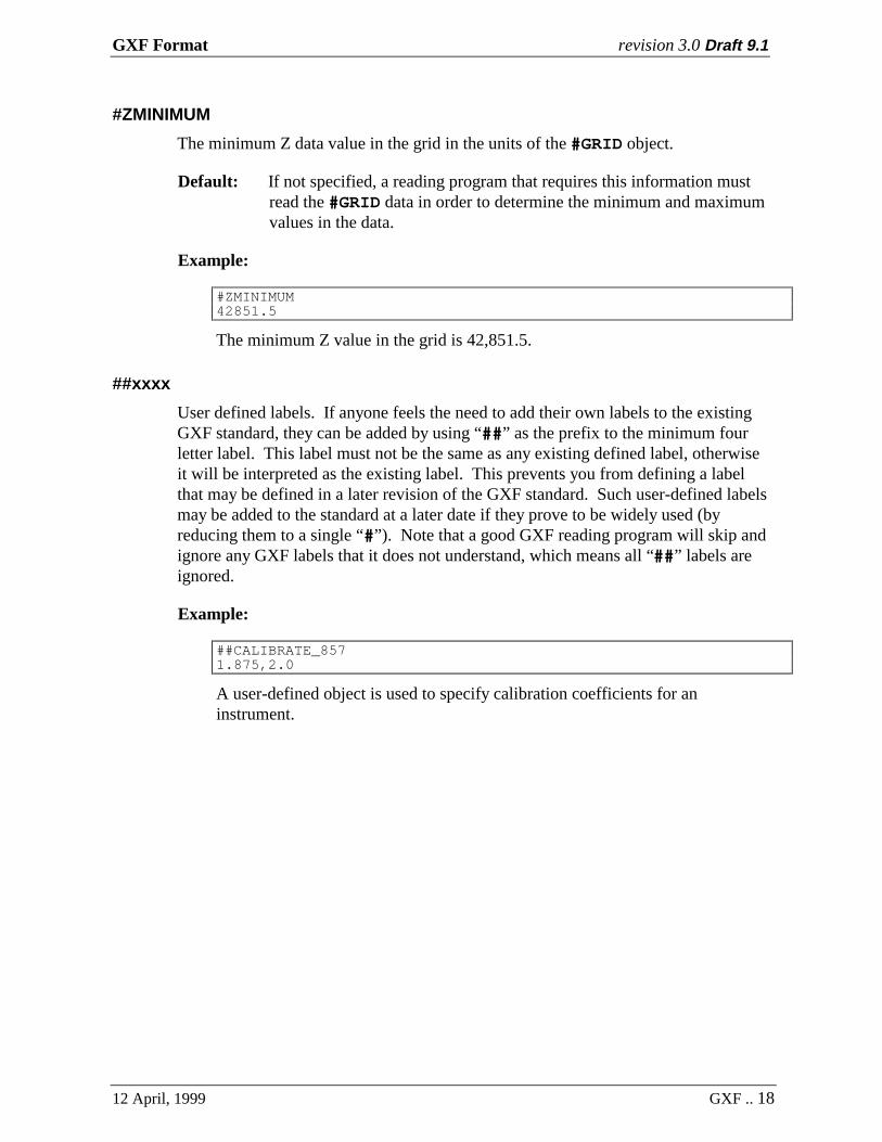
#ZMINIMUM
The minimum Z data value in the grid in the units of the #GRID object.
Default: If not specified, a reading program that requires this information mustread the #GRID data in order to determine the minimum and maximumvalues in the data.
Example:
#ZMINIMUM42851.5
The minimum Z value in the grid is 42,851.5.
##xxxx
User defined labels. If anyone feels the need to add their own labels to the existingGXF standard, they can be added by using “##” as the prefix to the minimum fourletter label. This label must not be the same as any existing defined label, otherwiseit will be interpreted as the existing label. This prevents you from defining a labelthat may be defined in a later revision of the GXF standard. Such user-defined labelsmay be added to the standard at a later date if they prove to be widely used (byreducing them to a single “#”). Note that a good GXF reading program will skip andignore any GXF labels that it does not understand, which means all “##” labels areignored.
Example:
##CALIBRATE_8571.875,2.0
A user-defined object is used to specify calibration coefficients for aninstrument.

GXF Format revision 3.0 Draft 9.1
12 April, 1999 GXF .. 19
5. NAME TABLESThe following tables are used to define a common set of key parameters for projections andunits used in GXF. The first column of each table is a key name, which is unique within eachtable. Key names that are not POSC compliant start with a “*” (asterisk) character.
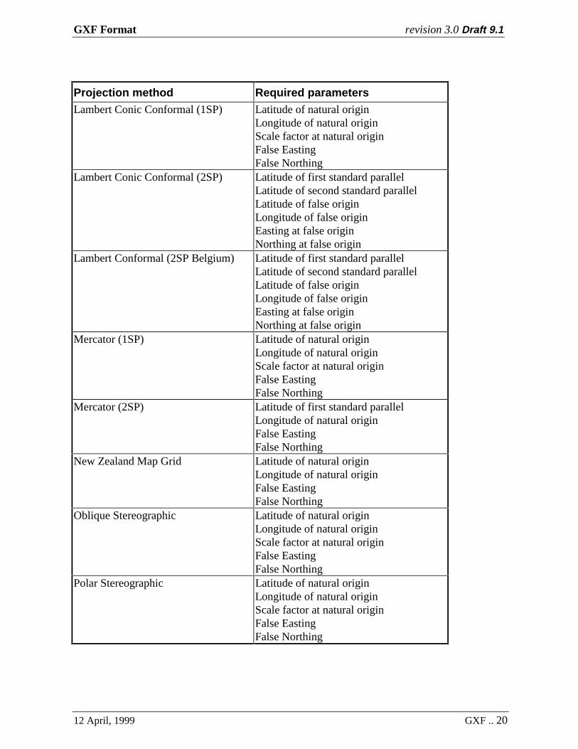
Table 1 Projection Transformation Methods
This table identifies all defined projection transformation methods. The parameters are listedin the order required in the #MAP_PROJECTION data object.
This table was compiled using EPSG (as of 1997/12/1) and POSC (2.2) as data sources. Theorder of parameters is based on the enumerated parameter order specified in the EPSG table“TRF_METHOD”, with unused parameters omitted. Should EPSG add new methods in thefuture, GXF support for those methods is implied, and the order of required parameters will beas defined by EPSG.
EPSG “Transverse Mercator (South Orientated)” is the same as POSC “Transverse Mercator(South Oriented)”, which corrects the spelling of “Oriented”.
Parameter Notes:• All distance references must be specified in meters.• All geographic references (latitudes and longitudes) are specified in degrees.• Longitudes in the Western hemisphere are negative.• Latitudes in the Southern hemisphere are negative.• Longitudes are relative to the prime meridian of the datum.
Projection method Required parametersGeographic No parameters. This indicates that
coordinates are longitudes and latitudes.Hotine Oblique Mercator Latitude of projection centre
Longitude of projection centreAzimuth of initial lineAngle from Rectified to Skew GridScale factor on initial lineFalse EastingFalse Northing
Laborde Oblique Mercator Latitude of projection centreLongitude of projection centreAzimuth of initial lineScale factor on initial lineFalse EastingFalse Northing
GXF Format revision 3.0 Draft 9.1
12 April, 1999 GXF .. 20
Projection method Required parametersLambert Conic Conformal (1SP) Latitude of natural origin
Longitude of natural originScale factor at natural originFalse EastingFalse Northing
Lambert Conic Conformal (2SP) Latitude of first standard parallelLatitude of second standard parallelLatitude of false originLongitude of false originEasting at false originNorthing at false origin
Lambert Conformal (2SP Belgium) Latitude of first standard parallelLatitude of second standard parallelLatitude of false originLongitude of false originEasting at false originNorthing at false origin
Mercator (1SP) Latitude of natural originLongitude of natural originScale factor at natural originFalse EastingFalse Northing
Mercator (2SP) Latitude of first standard parallelLongitude of natural originFalse EastingFalse Northing
New Zealand Map Grid Latitude of natural originLongitude of natural originFalse EastingFalse Northing
Oblique Stereographic Latitude of natural originLongitude of natural originScale factor at natural originFalse EastingFalse Northing
Polar Stereographic Latitude of natural originLongitude of natural originScale factor at natural originFalse EastingFalse Northing
GXF Format revision 3.0 Draft 9.1
12 April, 1999 GXF .. 21
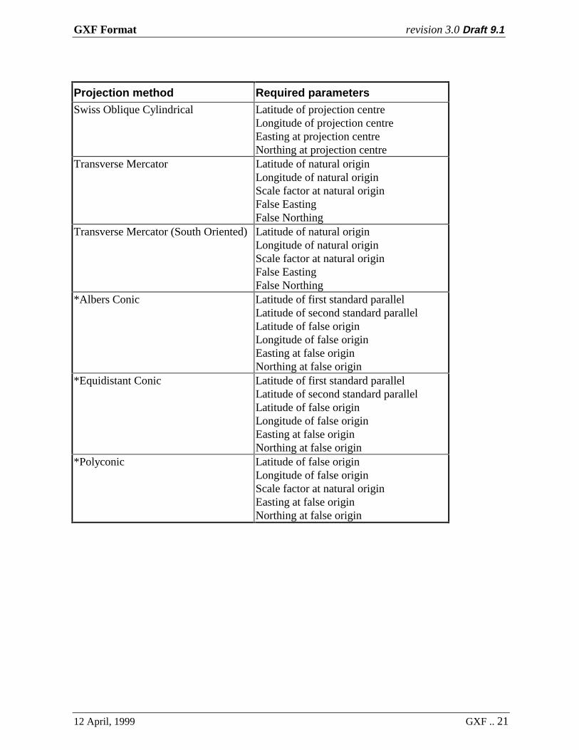
Projection method Required parametersSwiss Oblique Cylindrical Latitude of projection centre
Longitude of projection centreEasting at projection centreNorthing at projection centre
Transverse Mercator Latitude of natural originLongitude of natural originScale factor at natural originFalse EastingFalse Northing
Transverse Mercator (South Oriented) Latitude of natural originLongitude of natural originScale factor at natural originFalse EastingFalse Northing
*Albers Conic Latitude of first standard parallelLatitude of second standard parallelLatitude of false originLongitude of false originEasting at false originNorthing at false origin
*Equidistant Conic Latitude of first standard parallelLatitude of second standard parallelLatitude of false originLongitude of false originEasting at false originNorthing at false origin
*Polyconic Latitude of false originLongitude of false originScale factor at natural originEasting at false originNorthing at false origin

GXF Format revision 3.0 Draft 9.1
12 April, 1999 GXF .. 22
Table 2 Length Units
The following table is compiled from the UNIT_OF_LENGTH table in the EPSG tables. Theunit names are the abbreviations defined in EPSG. This table is for convenient reference only,and the EPSG table is considered the primary reference.
Unit Description Factor to metres
m Metre 1.0ft Foot 0.3048ftUS US survey foot 0.3048006096012ftMA Modified American foot 0.3048122529845ftCla Clarke’s foot 0.3047972651151ftInd Indian foot (Clarke) 0.3047995102481ftSe foot (Sears) 0.3047994715387lkCla link (Clarke) 0.201166194976lkBen link (Benoit) 0.2011678249438lkSe link (Sears) 0.2011676512155chBen chain (Benoit) 20.1167824943759chSe chain (Sears) 20.1167651215526ydSe yard (Sears) 0.914398414616ydInd Indian yard 0.9143985539701fathom Fathom 1.8288nautmi nautical mile 1852.0mGer German legal metre 1.0000135965dega degrees (angular) n/a
GXF Format revision 3.0 Draft 9.1
12 April, 1999 GXF .. 23
6. EXAMPLES
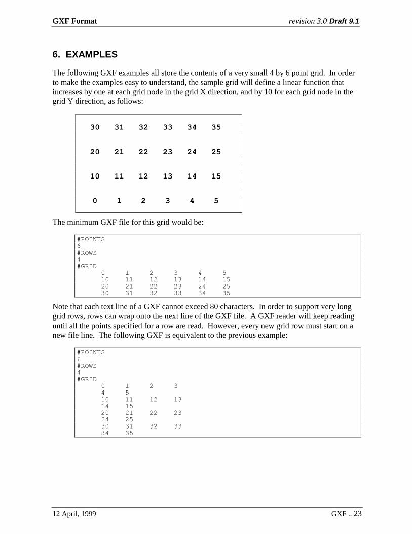
The following GXF examples all store the contents of a very small 4 by 6 point grid. In orderto make the examples easy to understand, the sample grid will define a linear function thatincreases by one at each grid node in the grid X direction, and by 10 for each grid node in thegrid Y direction, as follows:
30 31 32 33 34 35
20 21 22 23 24 25
10 11 12 13 14 15
0 1 2 3 4 5
The minimum GXF file for this grid would be:
#POINTS6#ROWS4#GRID
0 1 2 3 4 510 11 12 13 14 1520 21 22 23 24 2530 31 32 33 34 35
Note that each text line of a GXF cannot exceed 80 characters. In order to support very longgrid rows, rows can wrap onto the next line of the GXF file. A GXF reader will keep readinguntil all the points specified for a row are read. However, every new grid row must start on anew file line. The following GXF is equivalent to the previous example:
#POINTS6#ROWS4#GRID
0 1 2 34 510 11 12 1314 1520 21 22 2324 2530 31 32 3334 35

GXF Format revision 3.0 Draft 9.1
12 April, 1999 GXF .. 24
A more conventional GXF file would also include the separation between grid points and gridrows, and the location of the grid relative to some Base Coordinate System. GXF Revision 3provides for specifying coordinate systems, which should also be specified when known.
===========================================This is a comment area which is ignoredby GXF readers.===========================================#POINTS6#ROWS4
#PTSEPARATION12.5#RWSEPARATION12.5
#XORIGIN1750000.0#YORIGIN4250.0#ROTATION0.0
#UNIT_LENGTH"ftUS",0.3048006096012
#MAP_PROJECTION"NAD27 / Ohio North""NAD27",6378206.4,0.082271854,0"Lambert Conic Conformal (2SP)",40.4333333333,41.7,39.6666666667,\82.5,609601.22
#MAP_DATUM_TRANSFORM"NAD27 to WGS 84 (6)",-8,159,175,0,0,0,1
#GRID0 1 2 3 4 510 11 12 13 14 1520 21 22 23 24 2530 31 32 33 34 35

GXF Format revision 3.0 Draft 9.1
12 April, 1999 GXF .. 25
The next set of examples illustrates the effect of different storage senses. Note that the storagesense only effects the way in which the grid is stored in the GXF file. It does not change thegrid origin or rotation angle with respect to a base coordinate system, since these are definedwith respect to the bottom left corner of the grid. Examples for senses of +1, -1, +2 and -2 areshown since these are the most common formats anticipated:
#SENSE1#POINTS6#ROWS4#GRID0 1 2 3 4 510 11 12 13 14 1520 21 22 23 24 2530 31 32 33 34 35
#SENSE-1#POINTS4#ROWS6#GRID0 10 20 301 11 21 312 12 22 323 13 23 334 14 24 345 15 25 35
#SENSE2#POINTS4#ROWS6#GRID30 20 10 031 21 11 132 22 12 233 23 13 334 24 14 435 25 15 5
#SENSE-2#POINTS6#ROWS4#GRID30 31 32 33 34 3520 21 22 23 24 2510 11 12 13 14 150 1 2 3 4 5
Base-90 Compression
Uncompressed GXF data is human readable, and therefore has advantages as a grid exchangestandard because someone can work out the contents of the grid simply by looking at the GXFlisting. However, large grids can become unreasonably large in this format. For example, anairborne survey grid 1000 by 1000 points in size could be more than 15 megabytes ifexpressed as full precision ASCII numbers.
To deal with large grids, the GXF format supports compression using base-90 numbers in the#GRID object data. Base-90 digits use the ASCII character sequence 37 to 126 (% to ~),which are all printable characters. The resulting grid data is no longer human readable (unlessyou wish to learn base-90 numbering!), but the compressed GXF file can be smaller than anoriginal 4-byte binary grid
Compression requires that the grid values be converted to whole numbers (positive integers)with the use of the #TRANSFORM parameters, and that the #GTYPE object be present todefine the number of characters to be used for each base-90 number. Three characters shouldbe sufficient for almost all applications since it provides a precision of 1 part in 729,000.

GXF Format revision 3.0 Draft 9.1
12 April, 1999 GXF .. 26
The following three examples show the same grid in uncompressed format, then compressedformat, and finally compressed format with repeat compression.
Uncompressed GXF:
#ROWS8#POINTS10#DUMMY-9999#GRID -9999 -9999 -9999 -9999 -9999 -9999 -9999 -9999 -9999 -9999 -9999 -9999 -9999 -9999 -9999 -9999 -9999 -9999 -9999 -9999 -9999 -9999 -9999 -9999 -9999 1.0 2.5 0 -1.0 -9999 -9999 -9999 -9999 -9999 1.0 1.5 4.5 1.0 0 -9999 -9999 -9999 -9999 1.5 4.8 6.2 1.1 -1.6 -9999 -9999 -9999 -9999 4.6 9.1 11.5 -9999 -9999 -9999 -9999 -9999 -9999 -9999 3.1 1.6 0 -9999 -9999 -9999 -9999 -9999 -9999 -9999 -9999 0.5 -9999 -9999 -9999 -9999 -9999 -9999
Compressed GXF, without repeat compression:
#POINTS 10#ROWS 8#TRANSFORM 5.0E-03 -118.835#GTYPE 3#GRID!!!!!!!!!!!!!!!!!!!!!!!!!!!!!!!!!!!!!!!!!!!!!!!!!!!!!!!!!!!!!!!!!!!!!!!!!!!(5@(V^’y,’br!!!!!!!!!!!!!!!(5@(@J)),(5@’y,!!!!!!!!!!!!(@J)/h)Nr(7T’UT!!!!!!!!!!!!)+@*5@*j^!!!!!!!!!!!!!!!!!!!!!(c|(B^’y,!!!!!!!!!!!!!!!!!!!!!!!!(*6!!!!!!!!!!!!!!!!!!
Compressed GXF, with repeat compression:
#POINTS 10#ROWS 8#TRANSFORM 5.0E-03 -118.835#GTYPE 3#GRID%%/!!!%%/!!!%%*!!!(5@(V^’y,’br!!!%%)!!!(5@(@J)),(5@’y,!!!!!!!!!!!!(@J)/h)Nr(7T’UT!!!!!!!!!!!!)+@*5@*j^%%*!!!!!!!!!(c|(B^’y,%%*!!!!!!!!!!!!(*6%%+!!!

GXF Format revision 3.0 Draft 9.1
12 April, 1999 GXF .. 27
REFERENCES
Petrotechnical Open Software Corporation (POSC, www.posc.org)Software Integration Platform Specifications,
Version 2.2http://www.posc.org/Epicentre.2_2/SpecViewer.html
Coordinate system information can be found in the Subject Discussions under theEpicentre Logical Data Model heading on the POSC home page (as of 1998/3/7).
European Petroleum Survey Group (EPSG)EPSG Geodesy Parameters may be obtained from (as of January 22, 1999):http://www.petroconsultants.com/products/geodetic.html
Snyder, John P., Map Projections - A Working Manual, U.S. Geological Surveyprofessional paper 1395, U.S. Government Printing Office, 1987.