Embed Size (px)
Citation preview
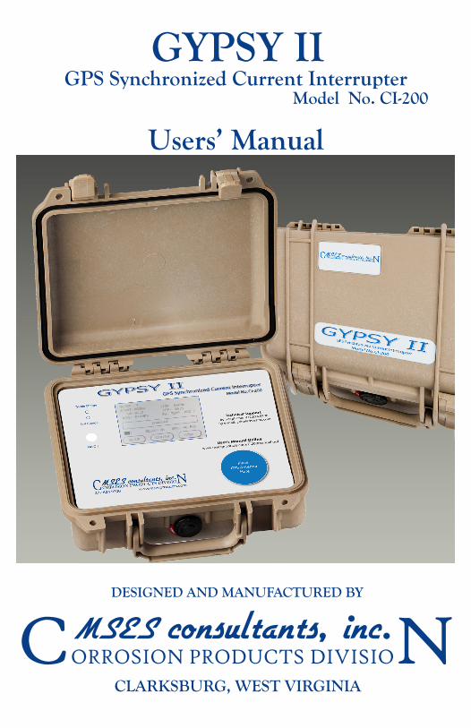
CORROSION PRODUCTS DIVISIONMSES consultants, inc.CLARKSBURG, WEST VIRGINIA
GYPSY II
Users’ Manual
DESIGNED AND MANUFACTURED BY
GPS Synchronized Current InterrupterModel No. CI-200

GYPSY II
GPS SYNCHRONIZED CURRENT INTERRUPTER
MODEL NO. CI-200
USERS’ MANUAL
(JULY 2010)
COPYRIGHT 2010
MSES CONSULTANTS, INC.CORROSION PRODUCTS DIVISION
CLARKSBURG, WEST VIRGINIA
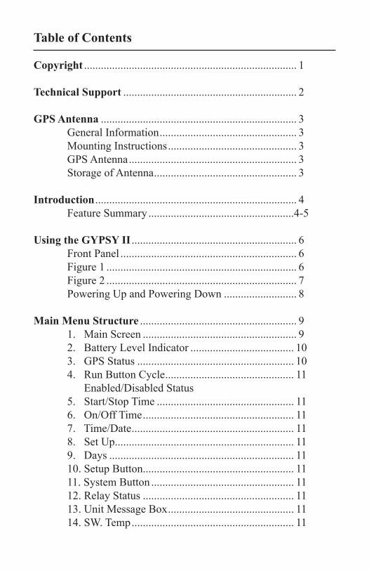
Copyright ............................................................................ 1
Technical Support .............................................................. 2
GPS Antenna ...................................................................... 3 General Information ................................................. 3 Mounting Instructions .............................................. 3 GPS Antenna ............................................................ 3 Storage of Antenna ................................................... 3
Introduction ........................................................................ 4 Feature Summary ....................................................4-5
Using the GYPSY II ........................................................... 6 Front Panel ............................................................... 6 Figure 1 .................................................................... 6 Figure 2 .................................................................... 7 Powering Up and Powering Down .......................... 8 Main Menu Structure ........................................................ 9 1. Main Screen ....................................................... 9 2. Battery Level Indicator ..................................... 10 3. GPS Status ........................................................ 10 4. Run Button Cycle .............................................. 11
Enabled/Disabled Status5. Start/Stop Time ................................................. 116. On/Off Time ...................................................... 117. Time/Date .......................................................... 118. Set Up................................................................ 119. Days .................................................................. 1110. Setup Button...................................................... 1111. System Button ................................................... 1112. Relay Status ...................................................... 1113. Unit Message Box ............................................. 1114. SW. Temp .......................................................... 11
Table of Contents
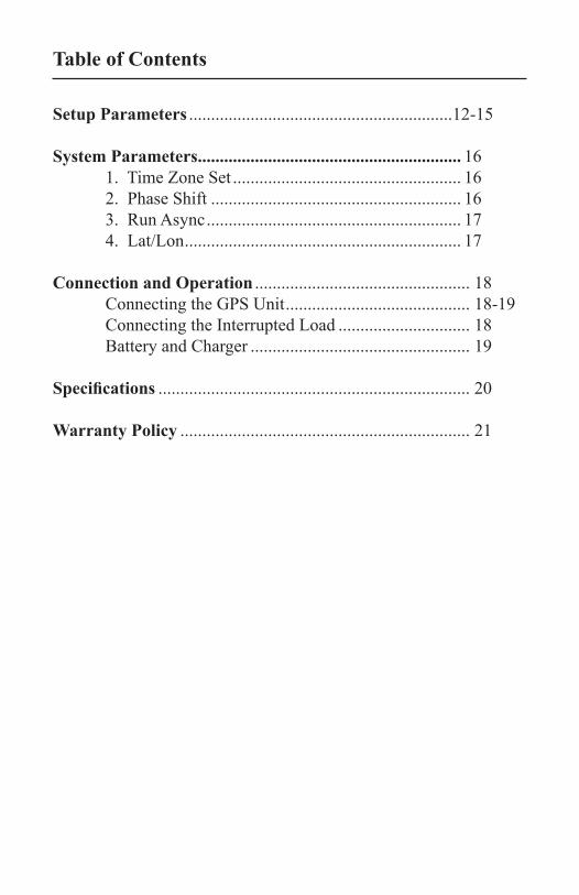
Setup Parameters ............................................................12-15
System Parameters ............................................................ 16 1. Time Zone Set .................................................... 16 2. Phase Shift ......................................................... 16 3. Run Async .......................................................... 17 4. Lat/Lon ............................................................... 17
Connection and Operation ................................................. 18 Connecting the GPS Unit .......................................... 18-19 Connecting the Interrupted Load .............................. 18 Battery and Charger .................................................. 19
Specifications ....................................................................... 20
Warranty Policy .................................................................. 21
Table of Contents
GYPSY II Page 1
Users’ Manual
The information contained in this manual is subject to change without notice and does not represent a commitment, either stated or implied, on the part of MSES Consultants, Inc. Corrosion Products Division.
Any and all reproduction or transmission of any part of this Users’ Manual, in any form or by any means and for any purpose other than the personal use by the purchaser, is strictly forbidden without the express written authorization of MSES Consultants, Inc. Corrosion Products Division.
All Rights Reserved© 2010 MSES Consultants, Inc.
Corrosion Products Division
GYPSY II Page 2
Technical Support
This Users’ Manual has been developed to provide you with all the information needed to correctly install, configure, and operate your GYPSY II GPS Synchronized Current Interrupter. Should you have questions or require assistance, after having acquainted yourself with the GYPSY II and the appropriate sections of this Users’ Manual, contact MSES Technical Support:
■ by telephone at 304.624.9700 (8:00 a.m. to 5:00 p.m. Eastern Standard Time, Monday through Friday except for Holidays)
■ by fax at 304.622.0981
■ by e-mail at [email protected]
This Users’ Manual (latest version) can be downloaded in Adobe’s Portable Document Format (PDF) from the MSES Technical Support website at www.msesproducts.com/CI200manual.pdf
GYPSY II Page 3
GPS Antenna
General Information
The GPS antenna is manufactured by Garmin® and provided for use with the GYPSY II unit. The GPS antenna is designed with a magnetic base that will provide a firm, yet removable, GPS antenna (sensor) mounting on a flat, ferrous metal surface.
Mounting Instructions
Choose a location on the mounting surface with a clear exposure to as much of the sky as possible. This is important because the antenna must “see” at least four (4) satellites clearly in order for the GYPSY II system to operate and provide the timing information. Therefore, you should avoid locating the antenna near vertical surfaces that will block the antenna from the satellite’s signal. Make sure the desired position of the mounting surface is flat. Route the GPS antenna cable to the GYPSY II unit, avoiding kinking or pinching of the cable.
GPS Antenna
The GPS antenna provided with the GYPSY II unit should remain with this unit for best results. Antenna should not be interchanged with other GYPSY II units.
Storage of Antenna
When the GYPSY II unit is not in use, the GSP antenna and cable can be stored within the GYPSY II unit case. An area is designed to hold the GPS antenna magnetically, and a Velcro® strap is provided for bundling the cable for storage within the unit.
GYPSY II Page 4
The GYPSY II provides a way to synchronize the interruption of electrical current with precise timing over a wide geographical area. Typical applications for the GYPSY II include synchronized rectifier current interruption along pipelines for measurement and analysis. The GYPSY II uses Global Positioning System (GPS) satellites to obtain exact timing information and to enable synchronization to accuracies in the millisecond range. Since all GYPSY II units use the same timing source (GPS), measurements at the “on-to-off” rectifier current boundary can be made with accuracy.
Feature Summary
GPS Synchronization - Using the GPS satellite system enables the GYPSY II to synchronize interruptions with +/- 1 microsecond accuracy.
Interruption Scheduling - The interruption schedule can be programmed by the user to start and stop at a specific time every day and the interrupter schedule can be set to interrupt on all days of the week or only on days set by the user. During non-interruption times, the rectifier operates normally.
Rectifier Compatibility - The GYPSY II executes interruption by a solid state current relay. The relay is compatible with most currently used rectifiers. In fact, the GYPSY II can be used for almost any application requiring the interruption of an electrical current (AC or DC).
Tri Power - The GYPSY II can operate on a standard 110 VAC power outlet, on rechargeable internal batteries, or from a 12V solar panel (not supplied with interrupter, optional accessory).
Rugged Construction - The GYPSY II is housed in a water-resistant (NEMA 4) case for protection from the elements in outdoor and industrial applications.
Introduction
GYPSY II Page 5
External Interruption Indicator - A green pilot light located on the front of the case near the left lock, when flashing, indicates the unit is synchronized and is interrupting.
GPS Location - The GPS antenna is both a transmitter and receiver, giving the user the ability to obtain the latitude and longitude of the GYPSY II unit.
Programming - The touch screen provides for a user friendly programming of the GYPSY II. The GYPSY II can be programmed to start the interruption cycle in the “on” or “off” position.
NOTE: The touch screen user interface should only be operated with the Users’ fingers, and should never be beaten or pounded on. Excessive pressure or heavy pounding on the screen can damage the touch screen!
Introduction
GYPSY II Page 6
Using the GYPSY II
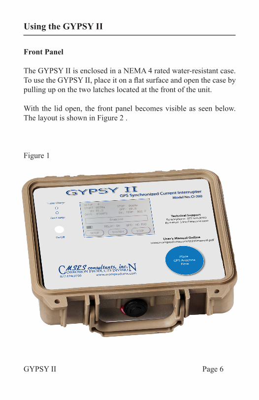
Front Panel
The GYPSY II is enclosed in a NEMA 4 rated water-resistant case. To use the GYPSY II, place it on a flat surface and open the case by pulling up on the two latches located at the front of the unit.
With the lid open, the front panel becomes visible as seen below. The layout is shown in Figure 2 .
Figure 1
GYPSY II Page 7
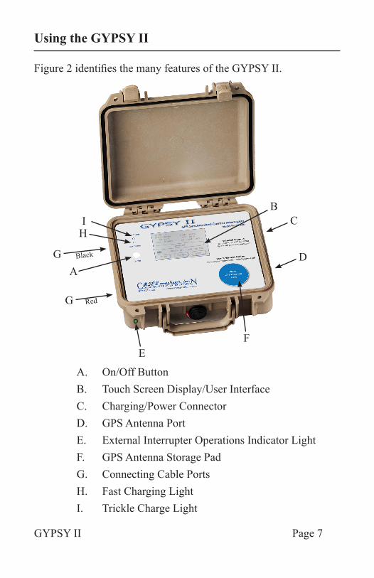
Figure 2 identifies the many features of the GYPSY II.
A. On/Off ButtonB. Touch Screen Display/User InterfaceC. Charging/Power ConnectorD. GPS Antenna PortE. External Interrupter Operations Indicator LightF. GPS Antenna Storage PadG. Connecting Cable PortsH. Fast Charging LightI. Trickle Charge Light
A
G
G
HI
BC
D
EF
Using the GYPSY II
Black
Red
GYPSY II Page 8
Powering Up and Powering Down
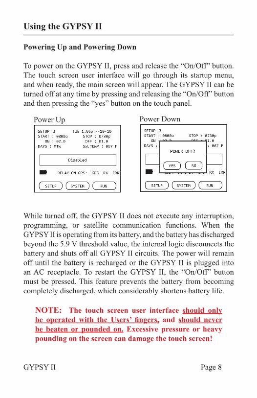
To power on the GYPSY II, press and release the “On/Off” button. The touch screen user interface will go through its startup menu, and when ready, the main screen will appear. The GYPSY II can be turned off at any time by pressing and releasing the “On/Off” button and then pressing the “yes” button on the touch panel.
While turned off, the GYPSY II does not execute any interruption, programming, or satellite communication functions. When the GYPSY II is operating from its battery, and the battery has discharged beyond the 5.9 V threshold value, the internal logic disconnects the battery and shuts off all GYPSY II circuits. The power will remain off until the battery is recharged or the GYPSY II is plugged into an AC receptacle. To restart the GYPSY II, the “On/Off” button must be pressed. This feature prevents the battery from becoming completely discharged, which considerably shortens battery life.
NOTE: The touch screen user interface should only be operated with the Users’ fingers, and should never be beaten or pounded on. Excessive pressure or heavy pounding on the screen can damage the touch screen!
Power Up Power Down
Using the GYPSY II
GYPSY II Page 9
Main Menu Structure
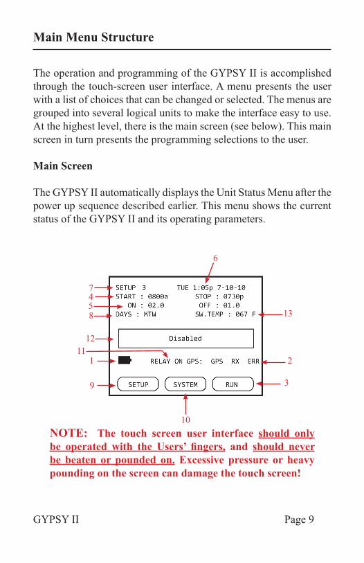
The operation and programming of the GYPSY II is accomplished through the touch-screen user interface. A menu presents the user with a list of choices that can be changed or selected. The menus are grouped into several logical units to make the interface easy to use. At the highest level, there is the main screen (see below). This main screen in turn presents the programming selections to the user.
Main Screen
The GYPSY II automatically displays the Unit Status Menu after the power up sequence described earlier. This menu shows the current status of the GYPSY II and its operating parameters.
NOTE: The touch screen user interface should only be operated with the Users’ fingers, and should never be beaten or pounded on. Excessive pressure or heavy pounding on the screen can damage the touch screen!
6
13
2
3
10
9
111
12
8547
GYPSY II Page 10
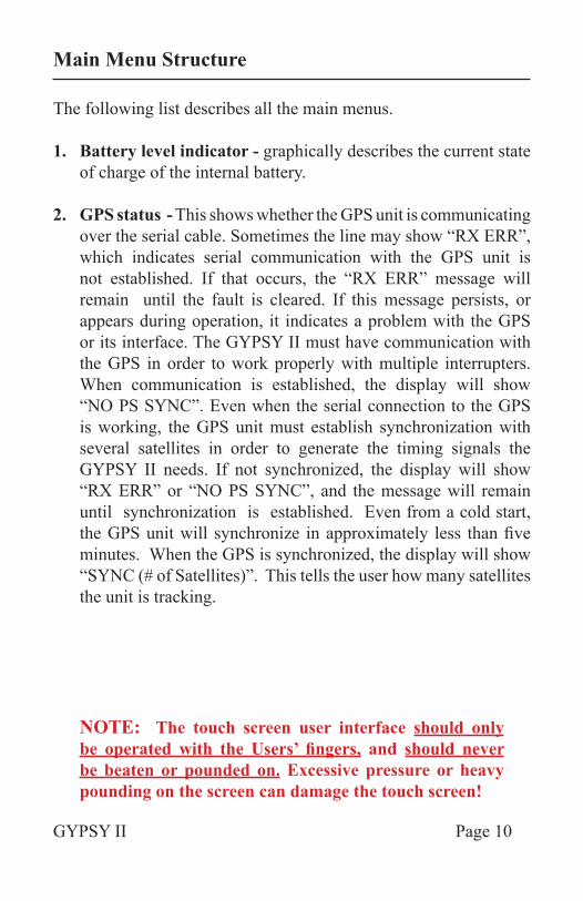
The following list describes all the main menus.
1. Battery level indicator - graphically describes the current state of charge of the internal battery.
2. GPS status - This shows whether the GPS unit is communicating over the serial cable. Sometimes the line may show “RX ERR”, which indicates serial communication with the GPS unit is not established. If that occurs, the “RX ERR” message will remain until the fault is cleared. If this message persists, or appears during operation, it indicates a problem with the GPS or its interface. The GYPSY II must have communication with the GPS in order to work properly with multiple interrupters. When communication is established, the display will show “NO PS SYNC”. Even when the serial connection to the GPS is working, the GPS unit must establish synchronization with several satellites in order to generate the timing signals the GYPSY II needs. If not synchronized, the display will show “RX ERR” or “NO PS SYNC”, and the message will remain until synchronization is established. Even from a cold start, the GPS unit will synchronize in approximately less than five minutes. When the GPS is synchronized, the display will show “SYNC (# of Satellites)”. This tells the user how many satellites the unit is tracking.
NOTE: The touch screen user interface should only be operated with the Users’ fingers, and should never be beaten or pounded on. Excessive pressure or heavy pounding on the screen can damage the touch screen!
Main Menu Structure
GYPSY II Page 11
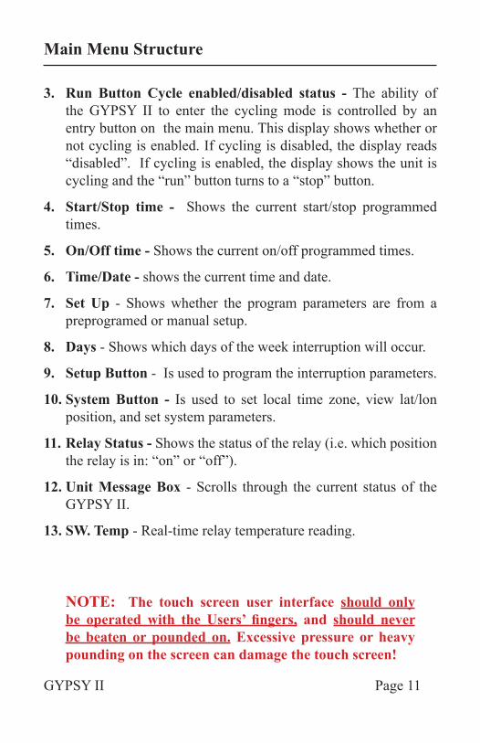
3. Run Button Cycle enabled/disabled status - The ability of the GYPSY II to enter the cycling mode is controlled by an entry button on the main menu. This display shows whether or not cycling is enabled. If cycling is disabled, the display reads “disabled”. If cycling is enabled, the display shows the unit is cycling and the “run” button turns to a “stop” button.
4. Start/Stop time - Shows the current start/stop programmed times.
5. On/Off time - Shows the current on/off programmed times.
6. Time/Date - shows the current time and date.
7. Set Up - Shows whether the program parameters are from a preprogramed or manual setup.
8. Days - Shows which days of the week interruption will occur.
9. Setup Button - Is used to program the interruption parameters.
10. System Button - Is used to set local time zone, view lat/lon position, and set system parameters.
11. Relay Status - Shows the status of the relay (i.e. which position the relay is in: “on” or “off”).
12. Unit Message Box - Scrolls through the current status of the GYPSY II.
13. SW. Temp - Real-time relay temperature reading.
NOTE: The touch screen user interface should only be operated with the Users’ fingers, and should never be beaten or pounded on. Excessive pressure or heavy pounding on the screen can damage the touch screen!
Main Menu Structure
GYPSY II Page 12
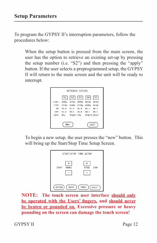
To program the GYPSY II’s interruption parameters, follow the procedures below:
When the setup button is pressed from the main screen, the user has the option to retrieve an existing set-up by pressing the setup number (i.e. “S2”) and then pressing the “apply” button. If the user selects a preprogrammed setup, the GYPSY II will return to the main screen and the unit will be ready to interrupt.
To begin a new setup, the user presses the “new” button. This will bring up the Start/Stop Time Setup Screen.
NOTE: The touch screen user interface should only be operated with the Users’ fingers, and should never be beaten or pounded on. Excessive pressure or heavy pounding on the screen can damage the touch screen!
Setup Parameters
GYPSY II Page 13
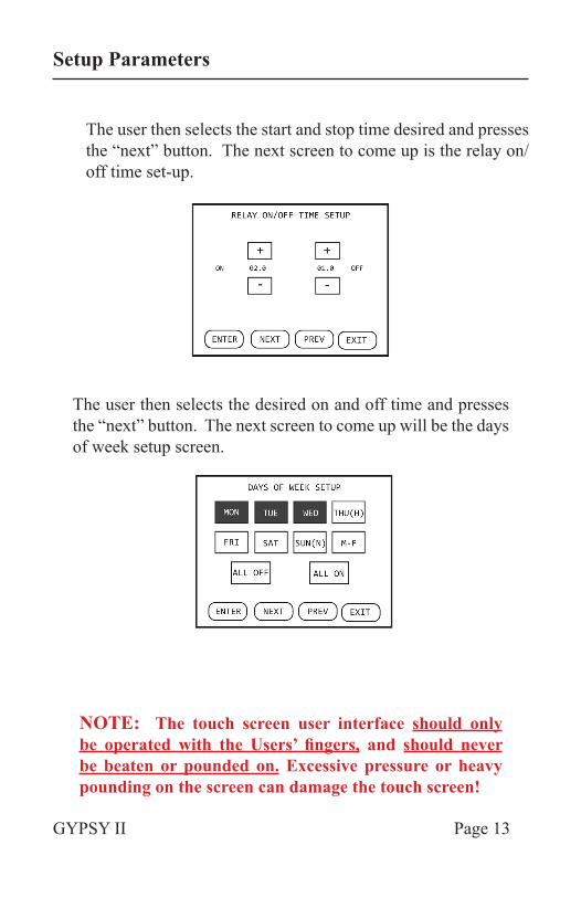
The user then selects the start and stop time desired and presses the “next” button. The next screen to come up is the relay on/off time set-up.
The user then selects the desired on and off time and presses the “next” button. The next screen to come up will be the days of week setup screen.
NOTE: The touch screen user interface should only be operated with the Users’ fingers, and should never be beaten or pounded on. Excessive pressure or heavy pounding on the screen can damage the touch screen!
Setup Parameters
GYPSY II Page 14
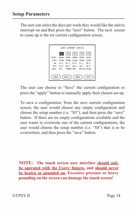
The user can select the days per week they would like the unit to interrupt on and then press the “next” button. The next screen to come up is the set current configuration screen.
The user can choose to “Save” the current configuration or press the “apply” button to manually apply their chosen set-up.
To save a configuration, from the save current configuration screen, the user would choose any empty configuration and choose the setup number (i.e. “S5”), and then press the “save” button. If there are no empty configurations available and the user wants to overwrite one of the current configurations, the user would choose the setup number (i.e. “S4”) that is to be overwritten, and then press the “save” button.
NOTE: The touch screen user interface should only be operated with the Users’ fingers, and should never be beaten or pounded on. Excessive pressure or heavy pounding on the screen can damage the touch screen!
Setup Parameters
GYPSY II Page 15
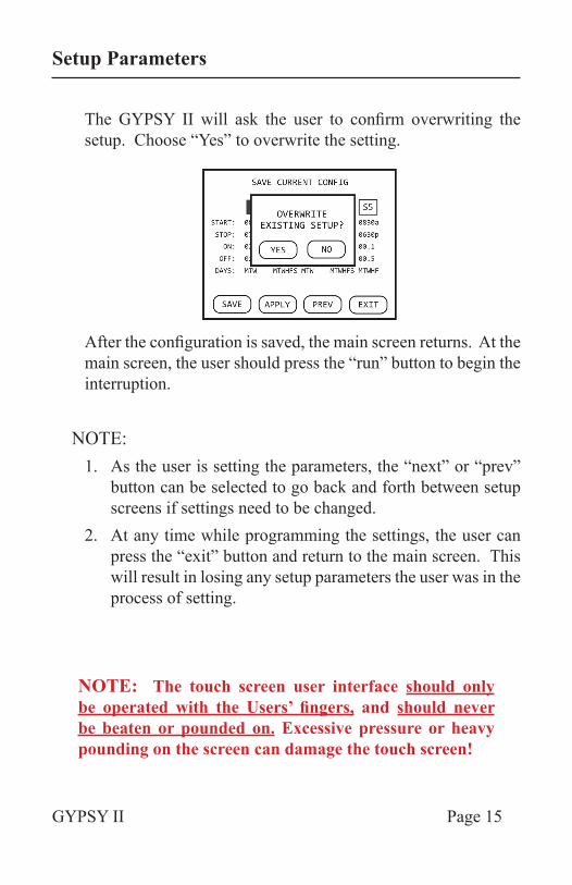
The GYPSY II will ask the user to confirm overwriting the setup. Choose “Yes” to overwrite the setting.
After the configuration is saved, the main screen returns. At the main screen, the user should press the “run” button to begin the interruption.
NOTE: 1. As the user is setting the parameters, the “next” or “prev”
button can be selected to go back and forth between setup screens if settings need to be changed.
2. At any time while programming the settings, the user can press the “exit” button and return to the main screen. This will result in losing any setup parameters the user was in the process of setting.
NOTE: The touch screen user interface should only be operated with the Users’ fingers, and should never be beaten or pounded on. Excessive pressure or heavy pounding on the screen can damage the touch screen!
Setup Parameters
GYPSY II Page 16
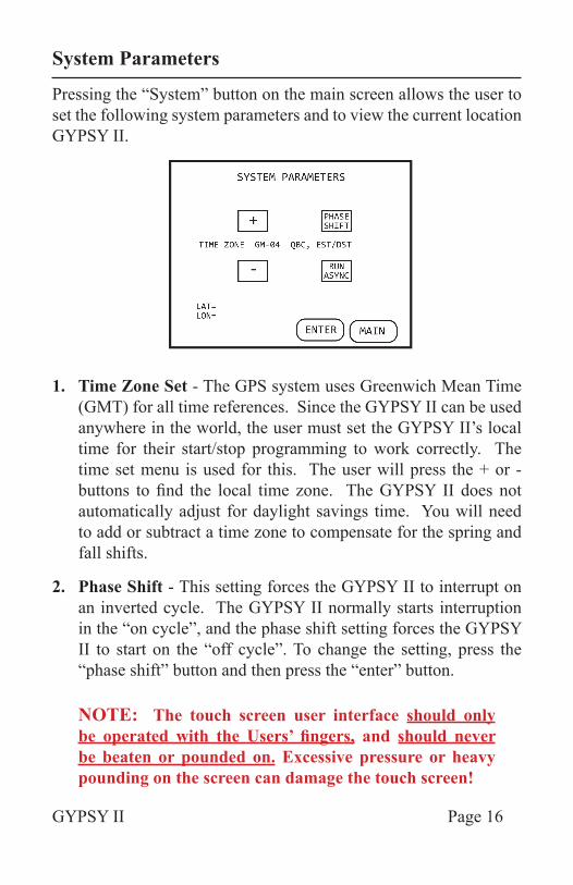
Pressing the “System” button on the main screen allows the user to set the following system parameters and to view the current location GYPSY II.
1. Time Zone Set - The GPS system uses Greenwich Mean Time (GMT) for all time references. Since the GYPSY II can be used anywhere in the world, the user must set the GYPSY II’s local time for their start/stop programming to work correctly. The time set menu is used for this. The user will press the + or - buttons to find the local time zone. The GYPSY II does not automatically adjust for daylight savings time. You will need to add or subtract a time zone to compensate for the spring and fall shifts.
2. Phase Shift - This setting forces the GYPSY II to interrupt on an inverted cycle. The GYPSY II normally starts interruption in the “on cycle”, and the phase shift setting forces the GYPSY II to start on the “off cycle”. To change the setting, press the “phase shift” button and then press the “enter” button.
NOTE: The touch screen user interface should only be operated with the Users’ fingers, and should never be beaten or pounded on. Excessive pressure or heavy pounding on the screen can damage the touch screen!
System Parameters
GYPSY II Page 17
3. Run Async - This menu choice is for use when one interrupter is needed without attaching the GPS unit. The GYPSY II unit will interrupt on any relay on/off time set-up chosen, but it will not recognize the start/stop time limits since the GPS is not attached. To choose this setting, press the “Run Async” button and then press “enter”.
4. Lat/Lon - When the GPS is attached and synced to at least four satellites, the unit will display its GPS location for reference purposes.
NOTE: The touch screen user interface should only be operated with the Users’ fingers, and should never be beaten or pounded on. Excessive pressure or heavy pounding on the screen can damage the touch screen!
System Parameters
GYPSY II Page 18
Connection and Operation
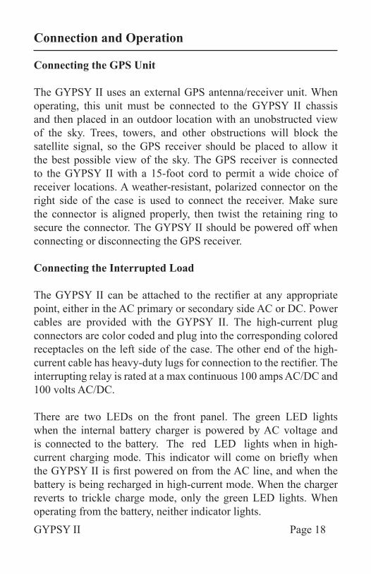
Connecting the GPS Unit
The GYPSY II uses an external GPS antenna/receiver unit. When operating, this unit must be connected to the GYPSY II chassis and then placed in an outdoor location with an unobstructed view of the sky. Trees, towers, and other obstructions will block the satellite signal, so the GPS receiver should be placed to allow it the best possible view of the sky. The GPS receiver is connected to the GYPSY II with a 15-foot cord to permit a wide choice of receiver locations. A weather-resistant, polarized connector on the right side of the case is used to connect the receiver. Make sure the connector is aligned properly, then twist the retaining ring to secure the connector. The GYPSY II should be powered off when connecting or disconnecting the GPS receiver.
Connecting the Interrupted Load
The GYPSY II can be attached to the rectifier at any appropriate point, either in the AC primary or secondary side AC or DC. Power cables are provided with the GYPSY II. The high-current plug connectors are color coded and plug into the corresponding colored receptacles on the left side of the case. The other end of the high-current cable has heavy-duty lugs for connection to the rectifier. The interrupting relay is rated at a max continuous 100 amps AC/DC and 100 volts AC/DC.
There are two LEDs on the front panel. The green LED lights when the internal battery charger is powered by AC voltage and is connected to the battery. The red LED lights when in high-current charging mode. This indicator will come on briefly when the GYPSY II is first powered on from the AC line, and when the battery is being recharged in high-current mode. When the charger reverts to trickle charge mode, only the green LED lights. When operating from the battery, neither indicator lights.
GYPSY II Page 19
After the GYPSY II has been programmed as desired, it is ready for operation. When everything has been set correctly, the watertight cover can be secured. The GYPSY II can be placed on the ground, suspended from the rectifier, or placed inside the rectifier case as desired. For the convenience of maintenance crews, a green LED is located on the case where it can be seen from a distance. This LED tracks the cycling of the relay and is lit during the interruption period. Note that this LED indicates interruption (relay energized, rectifier current OFF) rather than rectifier current ON.
Battery and Charger
When the GYPSY II is to be stored for an extended period (more than a week or two), the power should be turned off with the power “On/Off” button. This will prevent draining the battery completely. The batteries will self-discharge after several months, so the GYPSY II should be powered on from an AC source periodically to recharge the battery if the unit is not used for long periods.
The GYPSY II always recharges the battery when plugged into an AC outlet, even if the power switch is off. When on, the GYPSY II will run from AC as long as it is plugged in, and will run on battery when the AC is disconnected. The battery is automatically disconnected when its voltage falls below 3.5 volts.
Connection and Operation
GYPSY II Page 20
Specifications
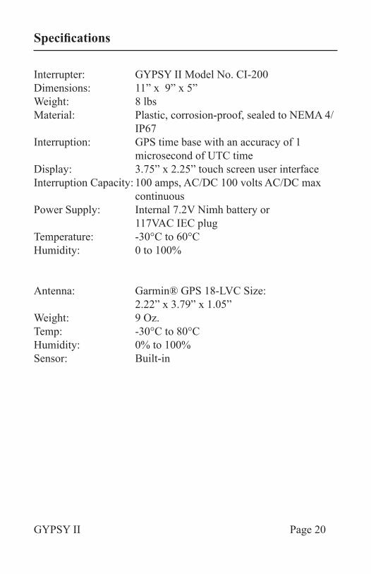
Interrupter: GYPSY II Model No. CI-200Dimensions: 11” x 9” x 5”Weight: 8 lbsMaterial: Plastic, corrosion-proof, sealed to NEMA 4/ IP67Interruption: GPS time base with an accuracy of 1 microsecond of UTC timeDisplay: 3.75” x 2.25” touch screen user interfaceInterruption Capacity: 100 amps, AC/DC 100 volts AC/DC max continuousPower Supply: Internal 7.2V Nimh battery or 117VAC IEC plugTemperature: -30°C to 60°CHumidity: 0 to 100%
Antenna: Garmin® GPS 18-LVC Size: 2.22” x 3.79” x 1.05” Weight: 9 Oz.Temp: -30°C to 80°C Humidity: 0% to 100%Sensor: Built-in
GYPSY II Page 21
GYPSY IIGSP SYNCHRONIZED CURRENT INTERRUPTER
MODEL NO.: CI-200
MSES Consultants, Inc. warrants this manufactured product to be free from defects in workmanship and materials for six months from date of purchase.
Prior written authorization from MSES Consultants, Inc. must be obtained to return any defective units, which must be returned to MSES Consultants, Inc. prepaid with a copy of the dated sales receipt within a maximum time period of six months following the original invoice date. MSES Consultants, Inc.’s obligation under the warranty is limited to the replacement or repair, at MSES Consultants, Inc.’s option, completely without charge for material or labor, any part found defective by MSES Consultants, Inc., and returned prepaid via ground service.
This limited warranty is in lieu of all other warranties expressed or implied, and any representations or promises inconsistent with or in addition to this warranty are unauthorized and shall not be binding upon MSES Consultants, Inc. In no event shall MSES Consultants, Inc. be liable for any special or consequential damages, whether foreseeable or not. This warranty shall be void if the product has been subject to misuse or damaged by negligence or accident, or if it has been repaired or altered by other than authorized agents of MSES Consultants, Inc.
Warranty Policy
GYPSY II Page 22
Users’ Notes
TECHNICAL SUPPORT
■ By telephone at 304.624.9700 (8:00 a.m. to 4:30 p.m. Eastern Standard Time, Monday through Friday except for holidays)
■ By fax at 304.622.0981
■ By e-mail at [email protected]
Model CI-200 SKU 705 2010 CPD/MSES All Rights Reserved
MSES consultants, inc.CORROSION PRODUCTS DIVISION609 West Main Street
PO Drawer 190Clarksburg, West Virginia 26302
THANK YOU FOR YOUR PURCHASE
WARRANTY
GYPSY II CI-200 is warranted free of defects and workmanship for six months from date of purchase. This GYPSY II CI-200 is warranted by Corrosion Products Division of MSES Consultants, Inc. to perform as described provided the GYPSY II CI-200 is used in accordance with the directions provided herein.