Embed Size (px)
DESCRIPTION
Project done during the EPICS I course at Colorado School of Mines. The gyroscope range of motion device measures the arm range of motion in degrees using an electronic gyroscope. This document provides an in depth of view of the various subsystem designs used to come up with the final prototype design.
Citation preview
Gyroscopic Joint Range of Motion Device
EPICS 151
Spring 2013
4/29/2013

Monday, April 29, 2013
Doctor’s Supply Inc.
4680 Edison Avenue Suite A
Colorado Springs, CO 80915
Dear Mr. Brunelle and Dr. Bach,
Grizzly Design submits this report to explain the team’s final design option for the range of
motion device and potential alternatives. On January 9, 2013, Doctor’s Supply Inc. asked us to
develop a more accurate and reliable electronic joint range of motion device. Since then, Grizzly
Design has developed a simple, easy to use, gyroscope device to solve this problem.
Grizzly Design has engineered a compact, reliable, and easy to use device to accommodate
Doctor Supply Inc.’s needs. The chosen design uses a gyroscope to reliably record maximum
and minimum angles of joint movement. Such a customizable and compact design will be easily
marketed and will not require the assistance of a specialist. Also included are alternative designs
that may also appeal to Doctor Supply Inc.
Grizzly Design is very excited to be working on this project and, with your permission, would
like to continue development of our design. You may contact Grizzly Design at
Thank you for your time,
Joe Meyer
Liaison, Grizzly Design
cc: Bob Neukirchner
Quinn Wolf
Loren Awalt
Tyler Rockley
Daevin Dev
Gyroscopic Joint Range of Motion Device
Design Report
Loren Awalt//Daevin Dev//Joe Meyer//Tyler Rockley//Quinn Wolf
Colorado School of Mines
EPICS 151 Section J
4/29/2013

Design Report for Gyroscope Range of Motion Device:
Executive Summary
Doctor’s Supply Inc. approached Grizzly Design with the task of researching and
designing a more reliable and easier to use smart device to measure joint range of motion in
physical joint therapy. The team developed a user friendly smart device with the capability of
automatically recording measurements while still being accurate and reliable. The main focus of
the design was to obtain the best data set possible while measuring joint range of motion. The
final design chosen revolves around the use of a gyroscope to measure the angle of joint motion.
The gyroscope is accurate to a hundredth of a degree and more precise than any other industry
standard angle measurement device. In fact, in preliminary testing, the device matched the
deviation in industry standard digital protractors that can cost at least twice as much.
Implementing a gyroscope allows for a super compact, versatile, and accurate design, which will
earn the approval of Doctor Supply Inc. and all physical therapists working with joint range of
motion.
The gyroscope itself and its necessary components are encased inside a sturdy and
durable ABS plastic box to protect it from the elements. All of the electronic components
interact through specially designed software which is fully customizable and adaptable to any of
the client’s or patients’ needs. The protective box for the gyroscope is made of durable,
lightweight material which is attached to a comfortable, lightweight strap. The strap wraps
around the wrist like a watch band and keeps the gyroscope and components securely attached to
the wrist. If a therapist wishes, a free weight can be added to ensure a constant and consistent
(between patients) force is applied to the joint. In this optional case, the patient will lie on their
back, hold the dumbbell at a ninety degree angle and slowly lower their arm to their shoulder.
Some of Grizzly Design’s alternate designs include an external frame goniometer brace
that was unoriginal, bulky, and less accurate. The team also worked on a simplified motion
capture device that used infrared and camera sensors to detect the range of motion. It was too
complex, difficult to use, and only accurate in certain circumstances. Fixing these problems, the
final design is very accurate and reliable, compact, inexpensive, versatile (it can be adapted to
any limb on any patient and can be customized to fit the patient’s exact needs), and easy to use.
An enormous advantage the final design has to other potential designs is its ability to be
marketed. The final cost is estimated and production is estimated to be only $15. Along with its
customizability and accuracy, the final gyroscope design will grasp the interests of all physical
therapists and promote Doctor Supply Inc.
Table of Contents
Introduction………………………………………………………………………………….…….1
Alternate Designs………………………………………………………………………………….1
External Frame Goniometer Brace…………………………………………..……………1
Simplified Motion Capture Using Infrared Mapping…………………………..…………2
Final Design……………………………………………………………………………………….2
Gyroscope…………………………………………………………………......…………..2
Electronics and Software………………………………………………………………………….3
Introduction…………………………………………………………………………..……3
Overall Physical Subsystem Analysis…………………………………..…………………3
Connections to Other Systems………………………………………………………….…3
How it Meets Client’s Requirements…………………………………………………...…3
The Gyroscope Unit…………………………………………………………………….…3
The Analog-to-Digital Converter……………………………………………….…………4
USB Cable and Port Specifications………….……………………………………………4
Software…………………………………………………………...………………………4
A Note about Customization………………………………………………………………5
Assembly…………………………………………………..………………………………5
Test Results………………………………………………..………………………………5
Summary……………………………………………………………..……………………6
Housing and Mounting…………………………………………………...……………………….6
Introduction……………………………………………………………..…………………6
Housing……………………………………………………………………………………6
Wrist Strap……………………………………………………...…………………………7
Assembly………………………………………………………..…………………………7
Summary………………………………………………………………..…………………7
Force System…………………………………………………………………………...………….8
Dumbbell…………………………………………………………………………..………8
Optional Constant-Tension Spring (used only in certain circumstances) ………...………8
Instruction Manual……………………………………………………………………..………….8
Introduction………………………………………………………………..………………8
Paper-Based Instruction Manual………………………..…………………………………9
Computer-Based User Interface Instructions……………….……………………………10
Summary…………………………………………………………………………………10
Operation and Maintenance………………………………………………………………..…….10
Operation…………………………………………………………………………………10
Maintenance…………………………………………………...…………………………10

Economic Analysis: $15 per unit…………………………………………………..…………….11
What’s Next……………………………………………………………………..……………….11
Summary………………………………………………………………………...……………….11
References…………………………………………………………………………………….….12
Figures………………………………………………………………………………...………….15
Appendix……...……………………………………………………………………………...…..23
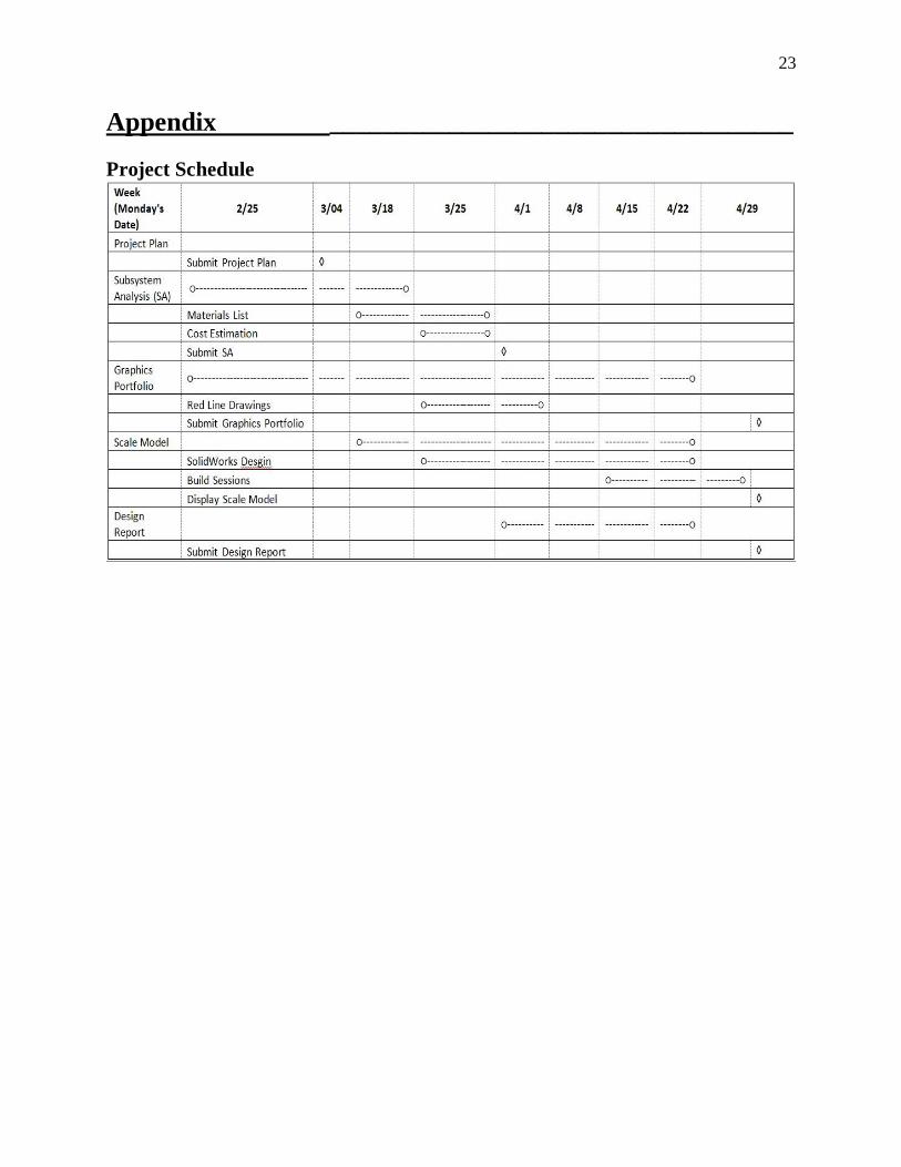
Project Schedule………………………………………………………….………………23
Team Contract……………………………………………………………………………24
1
Introduction ___________________________________
Doctor’s Supply Inc. approached Grizzly Design with the task of researching and designing a
more reliable and easier to use smart device to measure joint range of motion in physical joint
therapy. The team was asked to consider an electronic recording device, mounting fixtures, a
patient-readable scale, and the ability to monitor the force applied to the joint [1]. The main area
of focus is on the elbow but the device should be easily adapted to fit other joints as well. The
biggest constraints on the device are accuracy, reliability, and the production cost [1]. Grizzly
Design’s goal is to produce a device that incorporates all of the client’s needs into one simple
and easy to use device.
Grizzly Design developed a user friendly smart gyroscope device with the capability of
automatically recording measurements while still being very accurate and reliable. After
thorough research on the topic, the team has developed a compact final design that will meet all
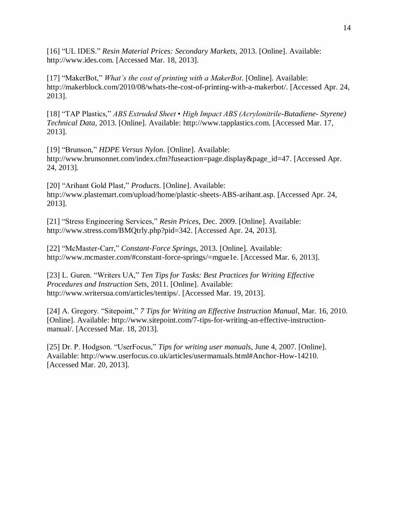
of Doctor Supply Inc.’s considerations. The final design incorporates a gyroscope to measure
joint range of motion as depicted in Figure 0 (a more detailed collection of figures can be found
in the Graphics Portfolio). The use of a gyroscope makes Grizzly Design’s device more reliable,
accurate and faster than currently used devices. Patients will also be able to automatically record
angle measurements to a nearby computer to check individual progress without the help of a
therapist. Incorporating a gyroscope to measure the joint range of motion allows for a compact
and customizable final design. The device can be fit to any size and can be used for more than
just the elbow. These considerations by Grizzly Design will make their device easily marketed in
the health industry.
This report will begin by discussing Alternate Designs that were considered in the early phases
of the design process. This is followed by a detailed description of the Final Design including
the four main subsystems: Electronics and Software, Housing and Mounting, Force, and
Instruction Manuals. It concludes with a operation and maintenance instructions followed by the
details of the cost estimate and the figures referenced throughout the report.
Alternative Designs___________________________________
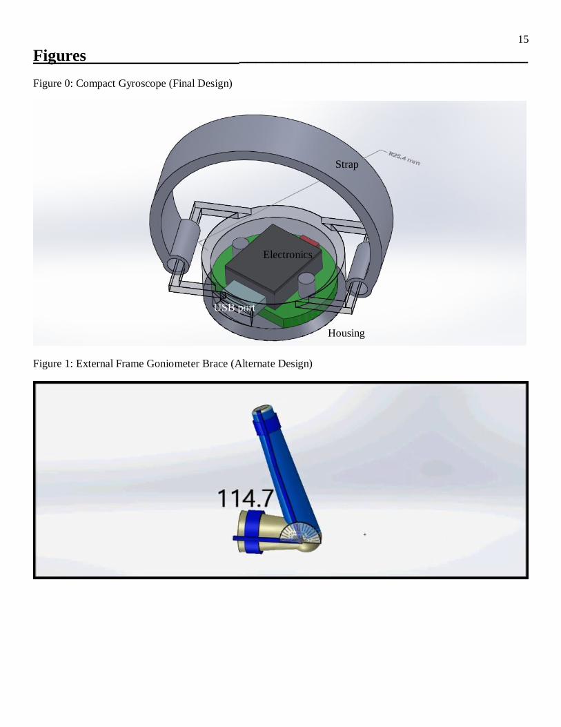
External Frame Goniometer Brace The first design proposed was based on current goniometers and elbow braces. The brace can be
consistently attached to a patient’s arm in line with the correct landmark points used for joint
2
range of motion measurement using calibrated hardware and straps. A digital protractor attached
to the brace would also line up with the landmark points, allowing for consistent measurements
from patient to patient and consistency between multiple measurements on the same patient. See
Figure 1. This design was not much different from the current goniometers, but it took away the
potential for error in lining up the goniometer to the patient’s landmark points on their arm. The
digital protractor is also much more accurate and precise than the current basic goniometers in
use. This design was eliminated because of its bulkiness, unoriginality, and difficulty to
universalize to any size patient.
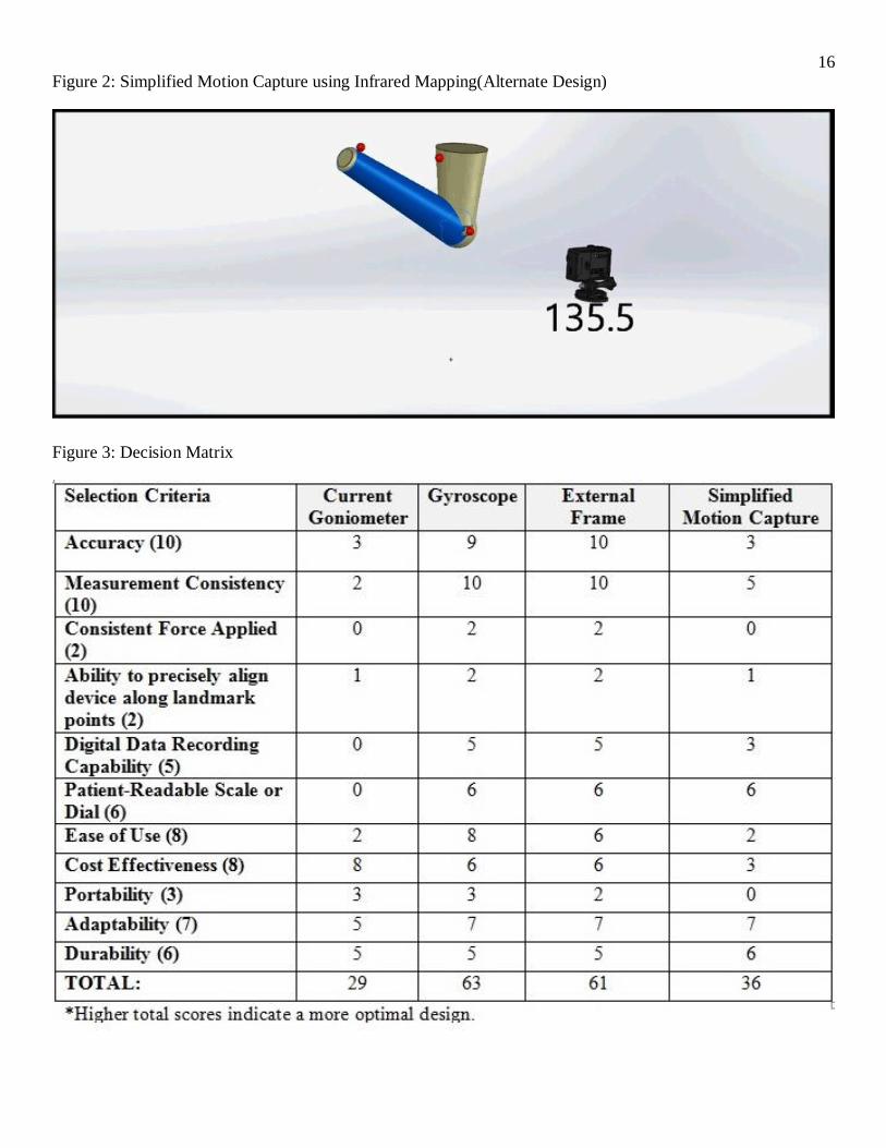
Simplified Motion Capture using Infrared Mapping Another alternative considered was an infrared motion mapping system to measure the range of
motion of a joint. Infrared markers would be placed like stickers on each of the landmark point,
and on the actual joint itself, and a camera would track the motion of the three points relative to
each other. See Figure 2. Software would determine an angle of movement from that tracking
data, which would be the final reading delivered to the patient [2]. As long as the motion was in
the same plane, and the markers were attached properly, this would be a very accurate system,
but it would be expensive relative to the other designs, much more complex, harder to use alone
or at home, and there could be inaccuracies in attaching the markers [3]. See Figure 3 for the
Decision Matrix used to quantify the advantages and disadvantages of these designs.
Final Design_________________________________________
Gyroscope The final design was picked for its advantages of compactness; accuracy; precision between
readings, patients, and therapists; ease of use; customizability; and low cost. The client’s most
important requests for the new design are accuracy and precision, and the gyroscope is both very
accurate and precise [1]. The gyroscope was tested against a digital protractor, and proved to be
just as accurate in measuring the angle. The gyroscope, however, is much more compact and
customizable than the digital protractor. The electronics and their protective enclosure could
easily be as small as a wristwatch. See Figure 0. The patient can simply strap the device onto
their wrist, zero it when the arm is fully extended, and then move their arm to its full range of
motion, as the gyroscope measures the angle. The gyroscope measures accurately as long as the
upper arm does not move, and it requires nothing more than a small device strapped to the
patient’s wrist. The device has a USB cable connected to a computer where the data from the
gyroscope is interpreted by a program and gives the patient a large-font view of their joint’s
angle of rotation. Because the data is recorded to the computer, it can all be stored electronically
and can be easily sent to a therapist to interpret the results and track the patient’s progress. The
nature of the gyroscope makes it compact, lightweight, and easy to use. It is easy for the patient
to use without a therapist present, allowing a single therapist to service more patients. The
current goniometers need to be lined up to landmark points on the patient to get a proper reading,
but the gyroscope only needs to be securely attached to the patient’s wrist (so that it does not
move relative to the wrist during the test), just like a watch, in order to get accurate readings.
This removes a lot of the error in current goniometer measurements by using relative changes
rather than absolute angles (which produce the same reading). The gyroscope device is a very
3
compact and easy to use design that does not sacrifice accuracy or precision, giving consistent
readings while being small enough to be comfortably worn and easily operated.
Electronics and Software ______________________________
Introduction This section outlines the details concerning the actual gyroscope, the processing unit, and the
software that makes the components work with very little user interaction. The actual gyroscope
itself and its necessary intermediate components are encased inside a sturdy and durable ABS
plastic box to protect it from the elements. This protected unit is attached to a watch-like brace
that connects it to the arm. See Figure 0. It starts with the overall layout and how the subsystem
fits in with the rest of the design and how it meets the client’s requirements. It then specifies the
details of the actual gyroscope, intermediate components, and software before concluding with
assembly information and testing results.
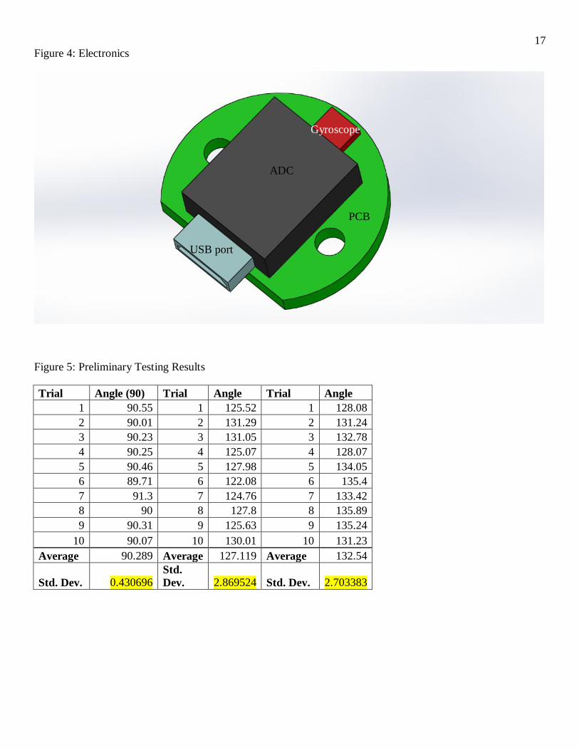
Overall Physical Subsystem Layout The gyroscope is connected to an analog-to-digital converter (ADC). The ADC is then
connected to a micro USB port that connects the computer to the device via a micro USB cable,
and the computer displays the angle of joint rotation. The entire system sits on a printed circuit
board (PCB) approximately the size of a wristwatch. See Figure 4.
Connections to Other Subsystems The PCB is glued to a watch band that straps onto the patient’s wrist. This entire system is
secured and enclosed inside a protective box that is attached to a brace that straps onto the lower
arm. See Figure 0.
How it Meets Client Requirements The electrical nature of the digital gyroscope is for accuracy and precision, which are the most
important aspects of this new range of motion device. Furthermore, the software is completely
automated and user-friendly so that the patient simply plugs the device into their computer and
does the test. This makes it extremely easy to use, another important client requirement [1].
The Gyroscope Unit How Gyroscopes Work
A gyroscope is simply a spinning wheel. Anything that spins has an angular momentum that
keeps it spinning in its current plane thus preserving the gyroscope’s orientation in space. This
resistance to a change in its orientation is called a Coriolis force [4]. Micro-electro-mechanical
(MEM) gyroscopes have been developed that use similar principles at a fraction of the size and
cost of the fully mechanical units. The digital gyroscope oscillates a small mass to produce the
displacement and when the gyroscope is rotated by an arm in physical joint therapy, there is a
Coriolis force that resists the initial displacement. Since the initial displacement is known, the
change can be measured as a capacitance difference that is then converted to an analog signal
that a computer can read [5].
Gyroscope Specifications
4
The gyroscope is a relatively simple silicon chip with 10 solder points to connect it to the PCB.
It is the LPY503AL model from Karlsson Robotics. It has dual axis capabilities (it can measure
the rotation of two axes simultaneously) and runs off of 3.3 volts with a sensitivity of 8.3 mV/º/s.
It is approximately 5mm x 5mm x 1.5mm in length, width, and height and weighs effectively
nothing. It costs about $5 retail [6]. See Figure 0. There is a direct relationship between cost
and precision in these digital gyroscopes, and that optimal tradeoff can be customized to fit the
client’s needs.
PCB Specifications
The printed circuit board (PCB) is circular in shape and approximately 30mm in diameter. The
exact shape and size of the board is based on how exactly the electrical engineer designs the
board. This means that it requires an outside consultant for a one-time design of the PCB. But
once it is designed once, it can be mass produced very inexpensively [7][8].
The Analog-to-Digital Converter The Analog-to-Digital converter (ADC) converts the analog signals which are just a flow of
electrons from the gyroscope into a binary number that can be transmitted through the USB port
to the computer [9]. The computer then performs all the calculations and displays the current
angle of rotation in a large font on the screen.
ADC Specifications
The ADC is a simple silicon chip with 8 solder points to connect it to the PCB. It is the
MCP3002 model from Karlsson Robotics. It has a 10-bit converter, which is more than enough
to get the desired .01 degree level of accuracy. It runs at just under 1MHz and also requires
3.3V. It is approximately 18mm x 15mm x 6mm in length, width, and height and weighs
effectively nothing. It costs $2.30 retail [10].
USB Cable and Port Specifications The USB port simply transfers the binary numbers from the ADC to the computer. It is the
standard Micro USB port from Karlsson Robotics. It is 4.8mm x 9.8mm x 2.9mm in length,
width, and height and weighs effectively nothing. It retails for $1.50 [11]. The cable is a 6-foot
(once again the length is customizable) male-to-male Type A to Micro USB cable. It retails for
less than $0.50 at a variety of outlets [12].
Software The software is the heart of this design. It is fully customizable and adaptable to any of the
client’s or patients’ needs. The patient simply plugs the USB cable into their computer and the
software automatically loads the instruction slides and then the necessary user interface for the
patient to conduct the test. The patient then gets in position, presses the start button on the
computer, then goes through the motion and the angle is displayed in real time right in front of
them on the computer screen. The patient presses the stop button and the program then saves the
angle for patient records. Since the software is open source, there is no need to re-download any
programs or be connected to the internet in any way; after a one-time download, the computer
recognizes the device and automatically opens the correct software so the patient can conduct
their tests.
5
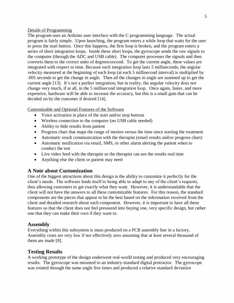
Details of Programming
The program uses an Arduino user interface with the C programming language. The actual
program is fairly simple. Upon launching, the program enters a while loop that waits for the user
to press the start button. Once this happens, the first loop is broken, and the program enters a
series of short integration loops. Inside these short loops, the gyroscope sends the raw signals to
the computer (through the ADC and USB cable). The computer processes the signals and then
converts them to the correct units of degrees/second. To get the current angle, these values are
integrated with respect to time. Because each integration loop lasts 5 milliseconds, the angular
velocity measured at the beginning of each loop (at each 5 millisecond interval) is multiplied by
.005 seconds to get the change in angle. Then all the changes in angle are summed up to get the
current angle [13]. It’s not a perfect integration, but in reality, the angular velocity does not
change very much, if at all, in the 5 millisecond integration loop. Once again, faster, and more
expensive, hardware will be able to increase the accuracy, but this is a small gain that can be
decided on by the customer if desired [14].
Customizable and Optional Features of the Software
Voice activation in place of the start and/or stop buttons
Wireless connection to the computer (no USB cable needed)
Ability to hide results from patient
Progress chart that maps the range of motion versus the time since starting the treatment
Automatic result communication with the therapist (email results and/or progress chart)
Automatic notification via email, SMS, or other alarm alerting the patient when to
conduct the test
Live video feed with the therapist so the therapist can see the results real time
Anything else the client or patient may need
A Note about Customization One of the biggest attractions about this design is the ability to customize it perfectly for the
client’s needs. The software lends itself to being able to adapt to any of the client’s requests,
thus allowing customers to get exactly what they want. However, it is understandable that the
client will not have the answers to all these customizable features. For this reason, the standard
components are the pieces that appear to be the best based on the information received from the
client and detailed research about each component. However, it is important to have all these
features so that the client does not feel pressured into buying one, very specific design, but rather
one that they can make their own if they want to.
Assembly Everything within this subsystem is mass produced on a PCB assembly line in a factory.
Assembly costs are very low if not effectively zero assuming that at least several thousand of
them are made [8].
Testing Results A working prototype of the design underwent real-world testing and produced very encouraging
results. The gyroscope was mounted to an industry-standard digital protractor. The gyroscope
was rotated through the same angle five times and produced a relative standard deviation
6
matching that of the digital protractor (.13%). This means that the gyroscope is at least as
precise as the industry-standard digital protractor. Later, the device underwent a rotation of 90° using the board as a right angle and produced a standard deviation of less than half a degree.
This is ten times better than current goniometers which are considered precise with a standard
deviation of 5 degrees. This test still had human error associated with it as the sides of the board
are not perfectly flat, but it was conducted to see how it performed off of the digital protractor.
Finally, the device was run through real-world simulations of actual joint range of motion tests.
This produced a consistent standard deviation of slightly less than 3 degrees. Most of this error
comes from the fact that nobody can rotate their arm the exact same amount ten times in a row.
Furthermore, the device was not strapped to the wrist, so a significant part of that error came
from relative movement between the device and the wrist, which does not happen when it is
worn with the strap.
Summary A digital gyroscope measures and calculates the angle of rotation and then displays it on a
computer screen while meeting all of the client’s requirements [1]. The gyroscope and ADC are
kept in a protective box and is then attached to a watch-like brace that secures it to the arm.
There is a USB cable connecting it to the computer that displays the current angle of rotation.
See Figure 0. The gyroscope is extremely accurate and precise and the software is explicitly
designed for ease of use. Experimental results proved promising and showed that the gyroscope
is at least as precise as industry-standard digital protractors. The software is fully customizable
and designed with patient ease of use in mind. There is a direct relationship between precision
and cost of the electronic components, which can be customized based on client’s needs. This
shows an important aspect of this design. It is fully customizable (or fully uncustomizable and
everywhere in between) to whatever the client wants or needs. Finally, this subsystem is mass
produced in a factory making assembly cost negligible (assuming high quantity). Total cost for
this system is estimated to be less than $10 retail.
Housing and Mounting ______________________________
Introduction This section details the protective housing for the gyroscope and its related electronic
components as well as the strap system used to attach the housing to the patient. It begins with
the protective housing for the electronics and explaining how it meets client’s requirements
before detailing the exact structure and how it fits into the other systems. It then moves on to
detailing the wrist strap and the assembly process.
Housing The gyroscope housing needs to be made out of a durable, lightweight material that is non-
conductive to avoid possible damage to the electronics; it should be as inexpensive as possible
while maintaining good structural durability. It needs to be stiff and able to be easily cleaned by
common chemicals and machines. The materials that were considered were: ABS plastic,
Aircraft Aluminum, and PVC plastic. The Aircraft Aluminum was more expensive than the
plastics and is much more conductive than the plastics. The PVC was inexpensive, but it was too
7
soft and did not have the required durability and was sensitive to chemicals and light [15].
Therefore, it was determined that ABS is the best material.
The housing is made of ABS plastic; ABS is very durable, costs only about $0.30/lb., is easily
formed into the necessary shapes, is non-conductive, resistant to chemicals, and is durable
enough to withstand continued use [16][17]. ABS has a flexural modulus of 300,000 psi [18] so
it resists deformation more than sufficiently for normal use. The client wanted a unit that was
durable enough to last for many uses, could be inexpensively produced for large scale
distribution, and could be used for a variety of patient sizes; therefore ABS is ideal for the
client’s specifications [1][15].
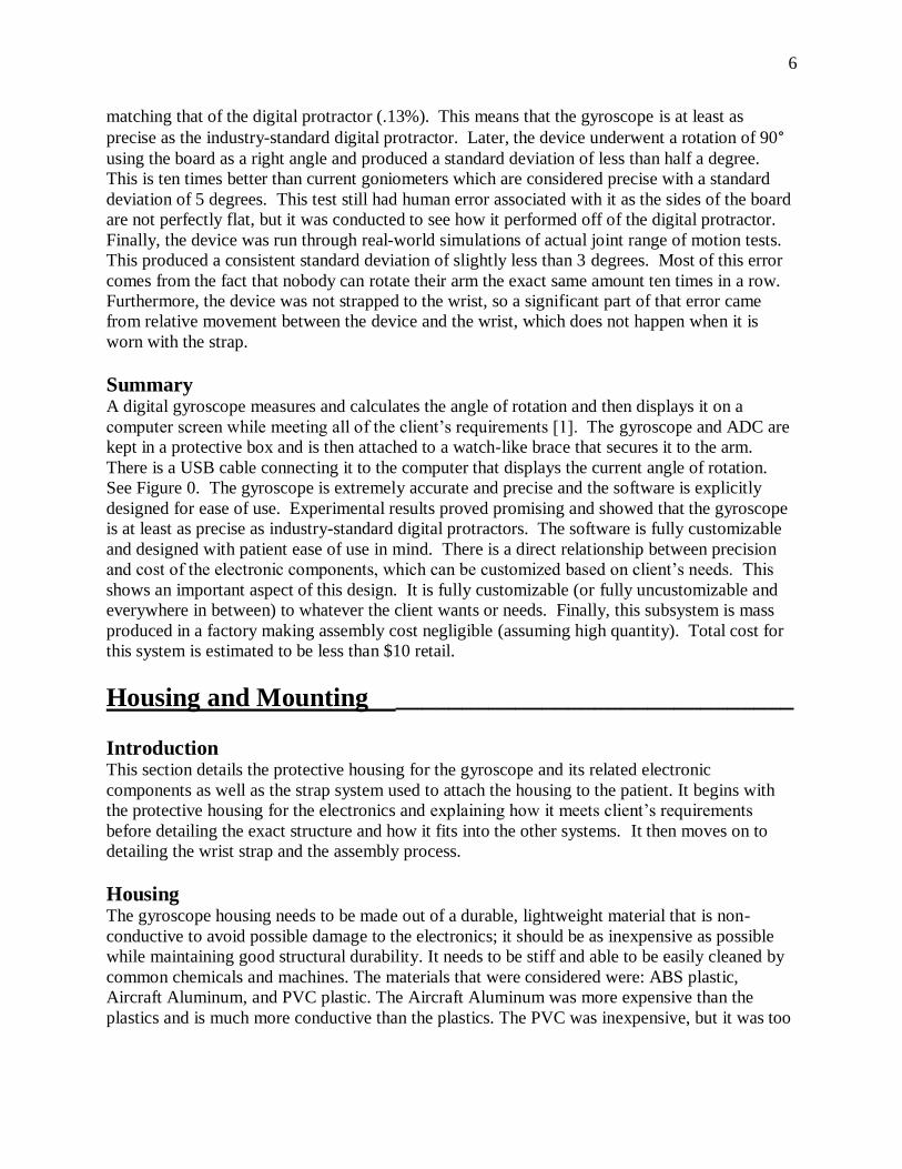
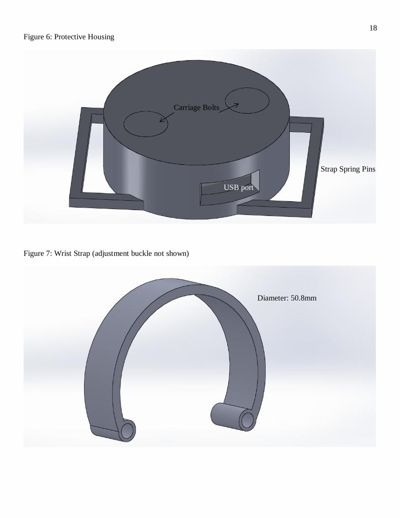
The Housing consists of a small circular back plate with two holes in it to secure the circuit
board and the back plate to the rest of the housing, and a cylindrical housing shell for the
electronics that has a small hole in it to accommodate the micro USB cable. The bolts used to
secure the housing together are carriage bolts to reduce any discomfort on the patient from the
bolts. See Figure 6.
The gyroscope housing and back plate consists of pieces of 2mm thick ABS plastic sheeting to
make a cylindrical shell around it with a rectangular whole open in one side for the computer
plug in. The bolts should be stainless steel to resist corrosion and possible allergic reactions of
the patients that could arise from the use of other metals.
Wrist Strap The wrist mounting system needs to be lightweight, flexible, easily cleaned, durable, and
comfortable for the patient. The best material would be some form of cloth or flexible plastic.
Materials that were considered were: nylon cloth, rubber, silicon, PVC, high-density
polyethylene (HDPE), and aircraft aluminum. Nylon was dismissed because it is not easily
cleaned between patients [19]. Silicon and PVC were both not durable enough to withstand
repeated use. Aluminum was also dismissed because it is considerably more expensive,
potentially difficult to adjust to different patients, and less comfortable. Rubber is more
expensive than HDPE and is less resistant to wear [20]. Therefore, HDPE is the optimal material
for the wrist strap, since it is durable, inexpensive at only about $0.65/lbs., easy to clean,
flexible, and relatively lightweight [21]. It is fashioned with a buckle system to secure it to
different sized wrists easily. See Figure 7.
Assembly The gyroscope housing is attached to the wrist strap by spring pins similar to that of a common
wrist watch. The electronics unit is attached to the protective housing by two carriage bolts. The
PCB has the carriage bolts running through it to the top of the housing to secure the electronics
unit inside the protective housing. See Figure 6. Assembly costs are approximately $3 due to
the tedious task of preparing and assembling the plastic and attaching the wrist strap.
Summary The housing and mounting system consists of 3 main pieces, the electronics unit, the protective
housing unit, and the wrist strap. The housing is constructed of ABS plastic. The electronics unit
is secured inside the protective housing by two carriage bolts. The housing is secured to the
8
wrist brace by a set of spring pins. See Figure 6. The wrist strap is made of HDPE with a buckle
system to secure it to a wide variety of patients (see Figure 7). The total estimated cost for this
system is less than $5.
Force System ______________________________
Dumbbell To apply a consistent force on the patient to ensure that there are no inconsistencies in the
readings caused by differing amounts of applied force, the patient will hold a known weight like
a dumbbell [1] in their hand. The exact amount of weight will be determined by the therapist but
will otherwise remain constant during therapy. To apply this force the patient will lay with their
back parallel to the ground and their arm to their side with the weight in their hand. The patient
will then raise their arm and bring it past the 90 degree point and then relax their arm so that the
weight will apply a constant force to the joint to assist in its bending. Since the weight will be
constant and no force from the patient or the therapist is used then the force applied will be
consistent for all readings during therapy. This system also does not require the therapist
presence to take readings, allowing for therapists to service a much greater number of patients
and for patients to take more readings to get a more reliable data set [1]. Assuming the therapist
or the patient has a dumbbell or other known weight, the cost of this system is zero.
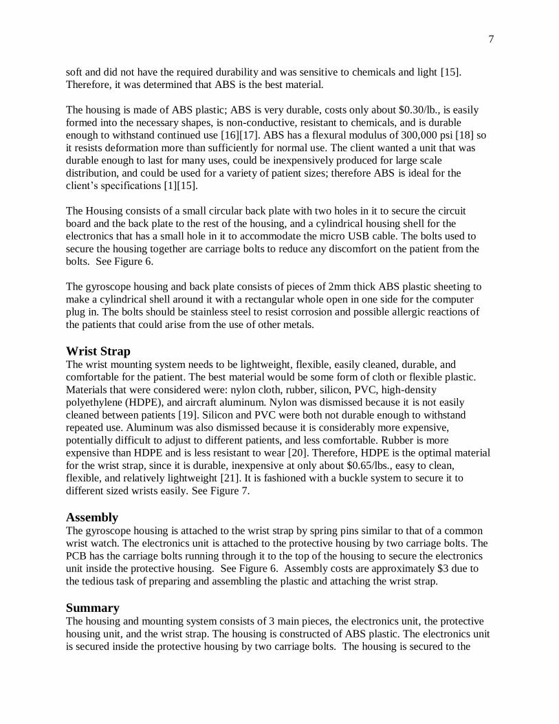
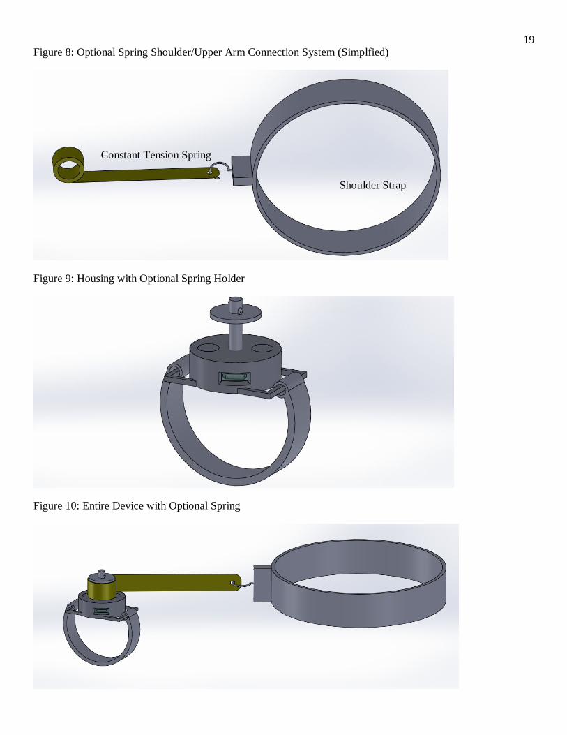
Optional Constant-Tension Spring (used only in certain circumstances) Another way of providing a constant and consistent force on the joint is to connect the lower
moveable part of the joint with the stationary upper part via a constant tension spring. Constant
tension springs provide the same amount of force no matter the extent of the spring extension.
They are the same springs used in tape measurers. They wind up into a convenient little cylinder
less than a cubic inch in volume. The solution is to attach it to the wrist mount, and to another
mount on the patient’s shoulder (see Figure 8). The wrist mount is simply a bolt that the spring
rests on as shown in Figures 9 and 10. This would apply a constant force to the joint, eliminating
the need for a therapist to apply a force and guess at whether or not it was actually constant or
consistent across different measurements. The spring used is from McMaster-Carr. It is
19.05mm in diameter and 12.7mm in width and can extend to 66cm in length (which is well
beyond the length of any arm). It provides a constant force of 7.2 newtons and retails for about
$10 [22]. The spring system does have a few safety and design concerns, which is why it is
optional. First, it is difficult to take off quickly should the patient reinjure the joint. Second, it is
bulky and almost doubles the cost of the device. However, it does not require the patient to lay
parallel to the floor, so a patient who has difficulty lying down can do the exercises against a
wall. It is also more accurate in providing a constant force all the way through the exercise.
Instruction Manual ______________________________
Introduction The instruction manual will serve as an overall comprehensive guideline for users on how each
component should be used to attain proper data. It will also contain troubleshooting information
and also regulatory code compliance information for each subsystem. The instruction manual is
9
divided into two components, namely the paper-based instruction manual and the computer-
based user interactive instruction and troubleshooting manual.
Paper-Based Instruction Manual The instruction manual is a medium for Grizzly Design to communicate the operating principal
of the gyroscope device to potential users in a simplified manner. The instruction manual will
consist of two main components; the paper-based manual (see Figure 11) and the computer-
based user interactive instructions (see Figures 12 and 13). It will contain assembly, usage,
maintenance, and safety precautionary information for all components of the device. The initial
instruction manual will be compiled in English with the assumption that potential users can read
and understand the English language. However, translated versions of the instruction manual can
be printed if deemed necessary in the future.
The following are the main components of the paper based instruction manual, arranged in order
of priority, along with a detailed description of what it entails:
Safety Instructions
This includes all safety precautions and warnings against unsafe actions concerning the
gyroscope and force system. This section is necessary to protect the safety of the patients and for
potential liability reasons as accidents may occur [23].
Product Diagram & Assembly Instructions
This section pertains to the assembly of the Gyroscope since it is a multiple-piece based product.
This section contains labeled pictorial instructions so users can easily visualize the assembly and
mounting process [24].
Software Installation/Requirements
This section is linked to the electronics and software subsystem. This section contains the initial
software installation setup for the gyroscope as well as software requirements such as a list of
supported computer operating systems. Users require this information in order to ensure their
computers are capable of installing the necessary software.
Quick Start Guide
This section contains a step by step guide to begin using the gyroscope device. Users read this on
their computer after having performed the software installation.
-Refer to the computer based user interactive instructions below.
Troubleshooting
This section contains information necessary for software, hardware or physical component
troubleshooting. It contains a logical and systematic set of guides for the user to first identify the
source of the problem and the corresponding solution to the problem. The information here is a
compilation of most likely error that could surface from other subsystem, and its solution.
Regulatory Code of Compliance
This section lists all compliance codes and standards to which the gyroscope device adheres to.
These codes are generally those from the International Standard of Organizations (ISO) and the
10
American National Standards Institutes (ANSI). A list of code of compliance is necessary since
the gyroscope is an electronic device. Potential users have the right to know that this electronic
device complies with all required standards. It reassures users that the device is safe to use.
Technical Specifications & Maintenance
This section contains all technical data regarding the device such as the type of electronic
component along with relevant model numbers. It also contains power, voltage, and current
information. The maintenance section provides simple maintenance procedures to ensure the
device is always in a proper working condition.
Warranty and Customer Support
The final section contains warranty and customer support contact information in case the device
needs repair or part replacement.
The physical manual itself is designed to maximize user readability and comprehension. It is in a
booklet form, printed on paper. See Figure 11. It has a high text-to-background contrast, which is
accomplished best with the colors black and white. The same font type and page layout are used
throughout the manual to avoid confusion. Varying font sizes are used to denote importance. The
text and images are arranged such that there is ample white space surrounding them. This is to
prevent the user from feeling overwhelmed with information [25].
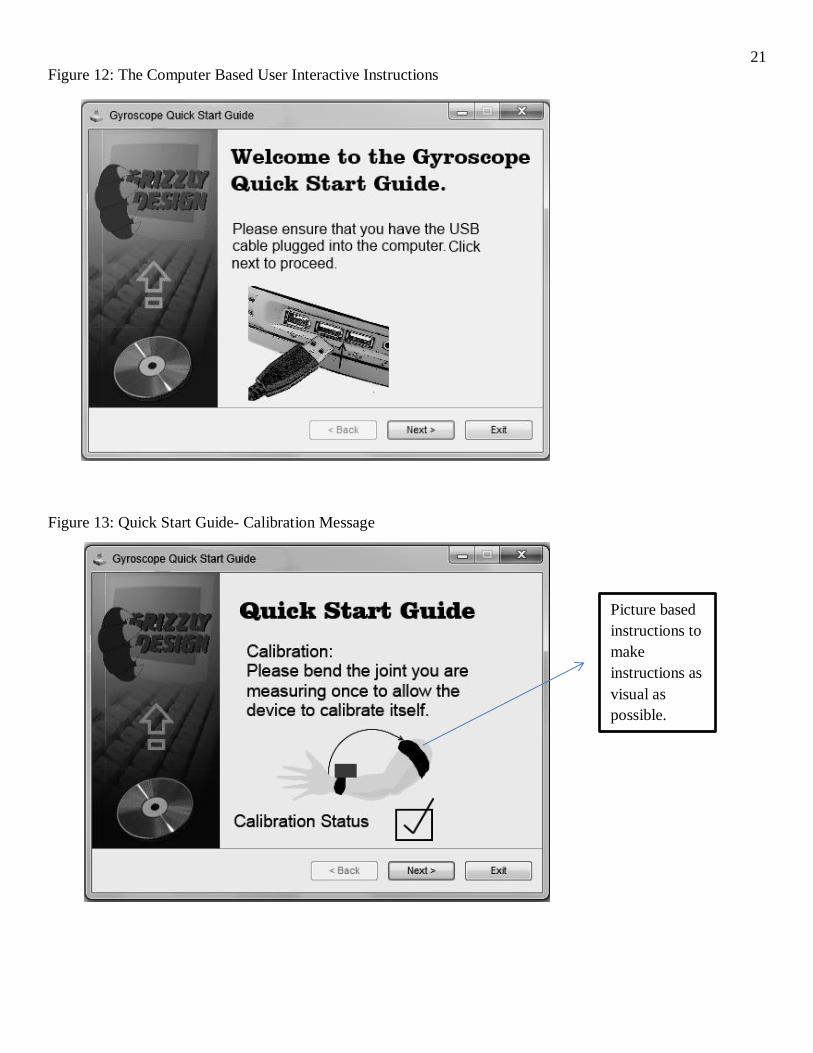
Computer Based User Interactive Instructions
Upon the initial setup, the user is prompted on the computer with a set of simple quick guide
steps to start using the device as depicted in Figure 12. The instructions here are pictorial and
animation based so as to make the operating principle as interactive and visual as possible. See
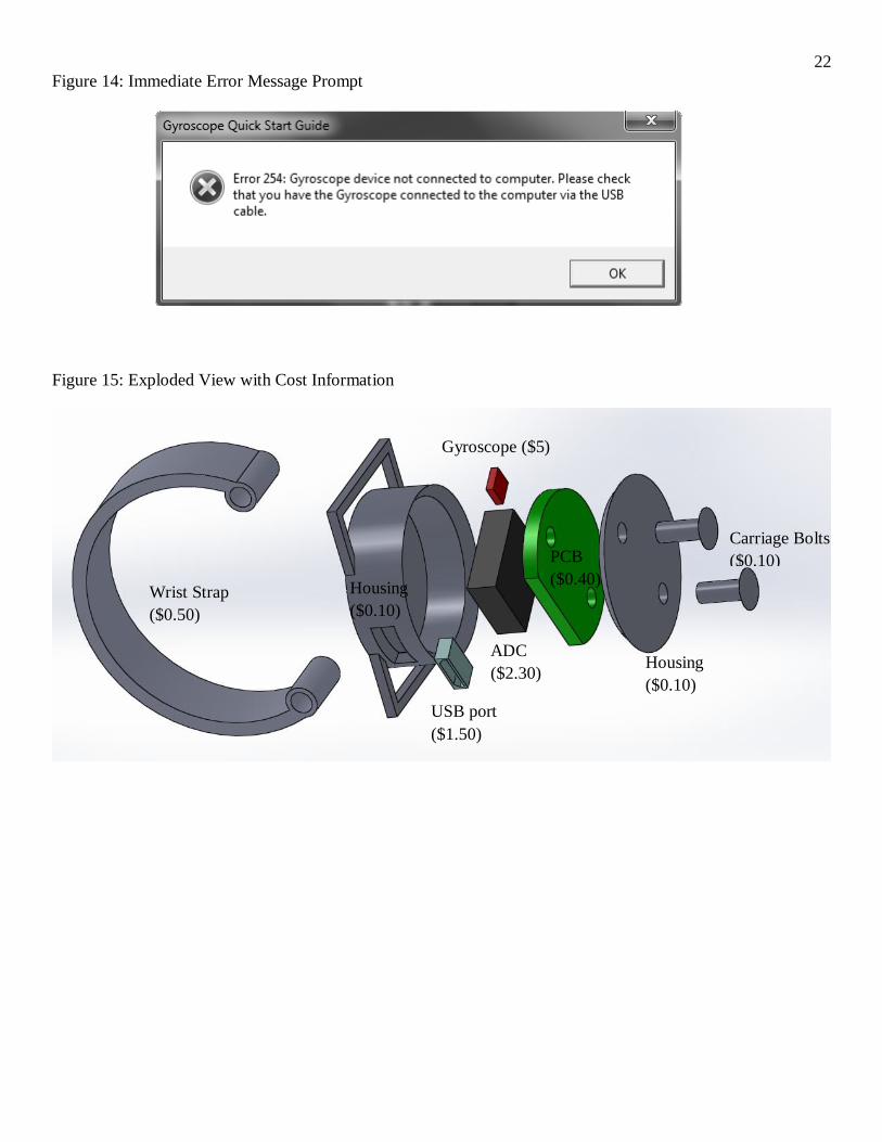
Figure 13. The interactive aspect allows the software to immediately detect any user based error
and prompt the user to make amends before proceeding to the next step as depicted in Figure 14.
Summary Overall, the instruction manual consists of two components, the paper based instruction manual
and the computer based user interactive instructions. Both components must be used jointly in
order to fully understand and successfully attain data from the gyroscope.
Operation and Maintenance ________________________
Operation One of the biggest advantages of the gyroscope design is that it is extremely easy to use. There
is a simple 4-step process that the patient follows to conduct their test effectively. First, the
patient straps on the device to their arm like a watch. Second, the patient fully extends the arm
keeping the upper arm still throughout the entire exercise. Third, the patient presses the start
button and begins the exercise. Fourth, the patient relaxes the arm after the 90 degree point and
lets the gravitational force pull the arm to the completion of the test.
Maintenance
11
The device is very stable and durable. The parts should only be damaged in the most violent of
situations. Patients can refer to the instruction manual for part replacement information. In
general, the device should be able to withstand above normal usage. For software issues,
patients can refer to the troubleshooting section of the instruction manual.
Economic Analysis: $15 per unit________________________
One of the main attractions of the gyroscope design is its low production cost. The materials
(electronic components, plastic, and watch strap) retail for about $11. This means that buying in
bulk and directly from the manufacturer will save around 10%-20%. The software and
instruction manual require a one-time consultant to professionally design it and work out all the
flaws. This cost per unit becomes only a few cents (for paper and ink) after several thousand
units are produced. Likewise, the PCB requires a one-time consultant to professionally design
the circuit board, but the cost per unit also becomes very small (less than $0.50) assuming
several thousand units are produced. Again, the electronics are assembled on the PCB in an
assembly line factory where the cost per unit is effectively nothing [8]. The production cost of
the housing unit is no more than $4 putting the entire device at about $15 per unit (see Figure
15). This is remarkably inexpensive for such an accurate and precise device that is also compact
and easy to use (see Figure 15).
What’s Next? ___________________________________
The gyroscope device is a very exciting and innovative design that will change the medical
world. Even so, Grizzly Design is still fully invested and committed in the device’s continual
progression and advancement. For example, the team, given the chance, would like to adapt the
device to all joints including multi-dimensional ones like hips, wrists, ankles, and fingers.
Furthermore, Grizzly Design would like to bring this technology into other professions like
sports training where angles of rotation of the arm would be useful to know while doing bicep
curls, for example. The possibilities are nearly endless and Grizzly Design looks forward to
working with Doctor’s Supply Inc. in developing this design and using it to help change the
world.
Summary ___________________________________
Grizzly Design is confident that their design is the best device to fulfill Doctor Supply Inc.’s
need for a new range of motion device. The new smart gyroscope has several advantages over
current devices. The design is compact and simply attaches to the wrist, which allows for
versatility between patients and limbs. From therapist to therapist, patient to patient, and reading
to reading the gyroscope is the most precise angle measurement device on the market (less than
half of a degree of deviation in preliminary testing) while still being cost effective. The device is
extremely simple to use and the display is patient readable, so a therapist is not necessary all the
time allowing each therapist to see more patients. Above all, the new device will give the best,
most accurate data set possible for joint range of motion [1].
12
Current joint measurement devices, such as goniometers, are not effective enough for current
physical therapy. They depend on therapists’ subjective judgment to read the measurement on a
protractor. There is a significant problem with accuracy and precision dealing with different
therapists, patients, and readings. Currently, a therapist is necessary to take the measurement,
and readings from different therapists cannot be compared because each therapist may read a
goniometer slightly different. Grizzly Design’s new smart device is able to fix all of these
problems while still remaining inexpensive. The cost estimate for the new device is around $15.
This price is slightly more than current goniometers, priced around$3-$10, but the accuracy,
durability, and customizability make the gyroscope device worth the extra cost. In fact, in
preliminary testing, the device matched the deviation in industry standard digital protractors that
can cost at least twice as much. The last consideration Grizzly Design solved was the ability to
measure force applied to the limb. The team decided to use standard weight, such as a dumbbell,
to keep a constant force contracting the limb. The weight will be completely optional and will
not be used by all patients. For more detailed information on all aspects of the design, a
collection of graphics, figures, and drawings can be found in the Graphics Portfolio.
Some of Grizzly Design’s alternate designs include an external frame goniometer brace that was
unoriginal, bulky, and less accurate. The team also worked on a simplified motion capture
device that used infrared and camera sensors to detect the range of motion. It was too complex,
difficult to use, and only accurate in certain circumstances. Fixing all these problems, the final
design is very accurate and reliable, compact, inexpensive, versatile (it can be adapted to any
limb on any patient and can be customized to fit the patient’s exact needs), and easy to use.
Grizzly Design is confident their design will greatly increase the efficiency of joint range of
motion devices. With the final design, all of Doctor Supply Inc.’s requirements have been
resolved in a simple compact device. The final design was chosen because it is accurate, precise
between patients and therapists, easy to use, and will be easily marketed. Grizzly Design is
excited and confident of their final design and hopes Doctor Supply Inc. is as well. If there are
any questions, Grizzly Design can be contacted through Joe Meyer at [email protected].
Thank you for choosing this team to help improve Doctor Supply Inc.’s product.
References ___________________________________
[1] B. Brunelle and R. Bach, “Smart Goniometer for Joint Physical Therapy,” Doctor’s Supply
Inc., Colorado Springs, CO, Colorado School of Mines, Jan. 2013.
[2] "Computing Research Association Distributed Mentor Project," Real-time Motion Capture,
Feb. 2013. [Online]. Available:
http://http://www.cs.utah.edu/~halzahaw/MotionCapture_main.html. [Accessed Feb. 24, 2013].
[3] “Occam Robotics,” Impulse Motion Capture, 2013. [Online]. Available:
http://www.occamrobotics.com/wp/?page_id=88. [Accessed Apr. 24, 2013].
[4] Gabriel Gache, "Softpedia," How do Gyroscopes Work?, Feb. 2008. [Online]. Available:
http://news.softpedia.com/news/How-do-Gyroscopes-Work-77809.shtml. [Accessed Mar. 17,
2013].

13
[5] J.E. Esfandyari, J.E. De Nuccio & J.E. Xu, "Solid Stats Technology: Insights for Electronics
Manufacturing," Introduction to Mems Gyroscopes, Nov. 2010. [Online]. Available:
http://www.electroiq.com/articles/stm/2010/11/introduction-to-mems-gyroscopes.html.
[Accessed Mar. 17, 2013].
[6] “Karlsson Robotics,” Dual Axis Gyro - LPR503AL - 30?/s, Mar. 2013. [Online]. Available:
https://www.karlssonrobotics.com/shop/dual-axis-gyro-lpr503al-30s/. [Accessed Mar. 28, 2013].
[7] “Wise Geek,” What Is a PCB?. [Online]. Available: http://www.wisegeek.com/what-is-a-
pcb.htm. [Accessed Apr. 24, 2013].
[8] “Bittele,” PCB Quote Online, Apr. 2013. [Online]. Available: http://www.bittele.com/pcb-
quote-
online_T.asp?total=38,378.75&a24=4&c5=100000&c7=3&e7=1&c9=0.031&c11=2&c13=1&c1
5=Green&c17=1&c19=1. [Accessed Apr. 24, 2013].
[9] “Analog Devices,” A/D Converters, 2013. [Online]. Available:
http://www.analog.com/en/analog-to-digital-converters/products/index.html. [Accessed Apr. 24,
2013].
[10] “Karlsson Robotics,” Analog to Digital Converter - MCP3002, Mar. 2013. [Online].
Available: https://www.karlssonrobotics.com/shop/analog-to-digital-converter-mcp3002/.
[Accessed Mar. 28, 2013].
[11] “Karlsson Robotics,” USB micro USB SMD Connector, Mar. 2013. [Online]. Available:
https://www.karlssonrobotics.com/shop/usb-micro-usb-smd-connector/. [Accessed Mar. 28,
2013].
[12] “MonoPrice,” 6ft USB 2.0 A Male to Micro 5pin Male 28/28AWG Cable, Mar. 2013.
[Online]. Available:
http://www.monoprice.com/products/product.asp?seq=1&format=2&p_id=4868&CAWELAID=
1329450556&catargetid=320013720000010917&cagpspn=pla&gclid=COOptN_G5rYCFck-
MgodehUAVw. [Accessed Mar. 28, 2013].
[13] “Arduino,” Guide to gyro and accelerometer with Arduino including Kalman filtering, Apr.
2011. [Online]. Available: http://arduino.cc/forum/index.php?topic=58048.0. [Accessed Feb. 24,
2013].
[14] “Hobby Electronics,” Accelerometer and Gyro Integration, 2013. [Online]. Available:
http://www.hobbytronics.co.uk/accelerometer-gyro. [Accessed Apr. 24, 2013].
[15] “Diffen,” ABS vs PVC. [Online]. Available:
http://www.diffen.com/difference/ABS_vs_PVC. [Accessed Apr. 24, 2013].
14
[16] “UL IDES.” Resin Material Prices: Secondary Markets, 2013. [Online]. Available:
http://www.ides.com. [Accessed Mar. 18, 2013].
[17] “MakerBot,” What’s the cost of printing with a MakerBot. [Online]. Available:
http://makerblock.com/2010/08/whats-the-cost-of-printing-with-a-makerbot/. [Accessed Apr. 24,
2013].
[18] “TAP Plastics,” ABS Extruded Sheet • High Impact ABS (Acrylonitrile-Butadiene- Styrene)
Technical Data, 2013. [Online]. Available: http://www.tapplastics.com. [Accessed Mar. 17,
2013].
[19] “Brunson,” HDPE Versus Nylon. [Online]. Available:
http://www.brunsonnet.com/index.cfm?fuseaction=page.display&page_id=47. [Accessed Apr.
24, 2013].
[20] “Arihant Gold Plast,” Products. [Online]. Available:
http://www.plastemart.com/upload/home/plastic-sheets-ABS-arihant.asp. [Accessed Apr. 24,
2013].
[21] “Stress Engineering Services,” Resin Prices, Dec. 2009. [Online]. Available:
http://www.stress.com/BMQtrly.php?pid=342. [Accessed Apr. 24, 2013].
[22] “McMaster-Carr,” Constant-Force Springs, 2013. [Online]. Available:
http://www.mcmaster.com/#constant-force-springs/=mgue1e. [Accessed Mar. 6, 2013].
[23] L. Guren. “Writers UA,” Ten Tips for Tasks: Best Practices for Writing Effective
Procedures and Instruction Sets, 2011. [Online]. Available:
http://www.writersua.com/articles/tentips/. [Accessed Mar. 19, 2013].
[24] A. Gregory. “Sitepoint,” 7 Tips for Writing an Effective Instruction Manual, Mar. 16, 2010.
[Online]. Available: http://www.sitepoint.com/7-tips-for-writing-an-effective-instruction-
manual/. [Accessed Mar. 18, 2013].
[25] Dr. P. Hodgson. “UserFocus,” Tips for writing user manuals, June 4, 2007. [Online].
Available: http://www.userfocus.co.uk/articles/usermanuals.html#Anchor-How-14210.
[Accessed Mar. 20, 2013].
15
Figures ___________________________________
Figure 0: Compact Gyroscope (Final Design)
Figure 1: External Frame Goniometer Brace (Alternate Design)
Strap
Electronics
Housing
USB port
16
Figure 2: Simplified Motion Capture using Infrared Mapping(Alternate Design)
Figure 3: Decision Matrix
17
Figure 4: Electronics
Figure 5: Preliminary Testing Results
Trial Angle (90) Trial Angle Trial Angle
1 90.55 1 125.52 1 128.08
2 90.01 2 131.29 2 131.24
3 90.23 3 131.05 3 132.78
4 90.25 4 125.07 4 128.07
5 90.46 5 127.98 5 134.05
6 89.71 6 122.08 6 135.4
7 91.3 7 124.76 7 133.42
8 90 8 127.8 8 135.89
9 90.31 9 125.63 9 135.24
10 90.07 10 130.01 10 131.23
Average 90.289 Average 127.119 Average 132.54
Std. Dev. 0.430696 Std.
Dev. 2.869524 Std. Dev. 2.703383
PCB
ADC
PCB
Gyroscope
USB port
18
Figure 6: Protective Housing
Figure 7: Wrist Strap (adjustment buckle not shown)
USB port
Carriage Bolts
Strap Spring Pins
Diameter: 50.8mm
19
Figure 8: Optional Spring Shoulder/Upper Arm Connection System (Simplfied)
Figure 9: Housing with Optional Spring Holder
Figure 10: Entire Device with Optional Spring
Constant Tension Spring
Shoulder Strap

20
Figure 11: Paper-Based Instruction Manual
21
Figure 12: The Computer Based User Interactive Instructions
Figure 13: Quick Start Guide- Calibration Message
Picture based
instructions to
make
instructions as
visual as
possible.
22
Figure 14: Immediate Error Message Prompt
Figure 15: Exploded View with Cost Information
Gyroscope ($5)
USB port
($1.50)
Gyroscope
Gyroscope
ADC
($2.30)
PCB
($0.40) Housing
($0.10)
Housing
($0.10)
Wrist Strap
($0.50)
Carriage Bolts
($0.10)
23
Appendix ___________________________________
Project Schedule

24
Team Contract
Grizzly Designs hereby declares a team contract to develop a professional system of
accountability for and understanding of expected behaviors while working in the team
environment.
Grizzly Designs paramount objective is to develop a revolutionary range-of-motion device for
Doctor’s Supply Inc. that meets all of the client’s needs as detailed in their letter to us. Grizzly
Designs also strives for all work to be completed and submitted on time and in a professional,
organized, and intelligent manner.
Team members should try to respectfully convey ideas and/or opinions.
For disagreements the team will vote, the majority decision will be upheld by the whole team.
Team members will be responsible for completing their assigned tasks on time.
Team members will not submit any important documents without first submitting them to
another team member for review.
All team members need to be functional and productive at all team meetings and team time.
If you cannot make a scheduled meeting time or due date inform any concerned parties as far in
advance as possible.
All projects should be completed as early as possible with a minimum of 24 hours prior to due
date.
All expenditures will be prior approved by the whole team and will be evenly divided. Any
disagreements will be decided by a majority vote. Any expenditure spent without the approval of
the team will be the responsibility of the involved parties.
If a team member has any grievances they will be brought up and addressed as needed.
These signatures represent the promise of the team members to uphold the terms of this contract
to the fullest extent of their ability and their understanding of the potential consequences for their
actions or their inability to honor this commitment.
Quinn Wolf Tyler Rockley Loren Awalt Deavin Dev Joe Meyer


![[PPT]Slide 1 - Department of Mechanical Engineering UET …mechanicalksk.weebly.com/.../g11_gyroscope_repeat.pptx · Web viewIntroduction Gyroscope : A gyroscope is a device for measuring](https://img.pdfslide.net/doc/110x75/5adeed1e7f8b9a5a668b8c04/pptslide-1-department-of-mechanical-engineering-uet-viewintroduction-gyroscope.jpg)