Embed Size (px)
Citation preview

H-2ADHD-QAM-IPLL
2 HDMI/YPbPr HD/SD IPTV
Encoder + RF Modulator
QAM, ATSC, DVB-T, ISDB-T
THOR BROADCAST
LOS ANGELES CA
1-800-521-8467

H-2ADHD-QAM-IPLL
A Note From Thor About This Manual
Intended Audience
This user manual has been written to help people who have to use, integrate and to install
the product. Some chapters require some prerequisite knowledge in electronics and
especially in broadcast technologies and standards.
Disclaimer
No part of this document may be reproduced in any form without the written permission of
Thor Broadcast.
The contents of this document are subject to revision without notice due to continued
progress in methodology, design and manufacturing. Thor shall have no liability for any
error or damage of any kind resulting from the use of this document.
Copy Warning
This document includes some confidential information. Its usage is limited to the owners of
the product that it is relevant to. It cannot be copied, modified, or translated in another
language without prior written authorization from Thor Broadcast.

H-2ADHD-QAM-IPLL
Directory
CHAPTER 1 INTRODUCTION ........................................................................................................................... 1
1.1 PRODUCT OVERVIEW .................................................................................................................................... 1
1.2 KEY FEATURES .............................................................................................................................................. 1
1.3 SPECIFICATION .............................................................................................................................................. 2
1.4 APPEARANCE AND DESCRIPTION................................................................................................................... 3
CHAPTER 2 INSTALLATION GUIDE .................................................................................................................. 6
2.1 GENERAL PRECAUTIONS ............................................................................................................................... 6
2.2 POWER PRECAUTIONS ................................................................................................................................... 6
2.3 DEVICE’S INSTALLATION FLOW CHART ILLUSTRATED AS FOLLOWING .......................................................... 6
2.4 ENVIRONMENT REQUIREMENT ..................................................................................................................... 6
2.5 GROUNDING REQUIREMENT ......................................................................................................................... 7
CHAPTER 3 OPERATION ................................................................................................................................. 8
3.1 3.1 LCD MENU STRUCTURE ......................................................................................................................... 8
3.1 INITIAL STATUS ............................................................................................................................................. 9
3.2 GENERAL SETTING FOR MAIN MENU .......................................................................................................... 10
CHAPTER 4 WEB NMS OPERATION............................................................................................................... 18
4.1 LOGIN ......................................................................................................................................................... 18
4.2 OPERATION ................................................................................................................................................. 19
CHAPTER 5 OPERATION OF CLOSED CAPTION (CC) ....................................................................................... 29
CHAPTER 6 LOW DELAY SETTING ................................................................................................................. 30
CHAPTER 7 TROUBLESHOOTING .................................................................................................................. 32
CHAPTER 8 PACKING LIST............................................................................................................................. 33

H-2ADHD-QAM-IPLL
1
https://thorbroadcast.com [email protected] 800-521-8467
Chapter 1 Introduction
1.1 Product Overview
The Thor Broadcast H-2ADHD-QAM-IPLL is our new all-in-one devices that integrates encoding
(MPEG-2, MPEG-4/AVC H.264) and modulation to convert HDMI/YPbPr /CVBS (Pr in) signals
etc to digital RF output. To meet customers’ various requirements, the H-2ADHD is also equipped
with 1 ASI input, and output with 2 ASI ports and 1 IP port.
The signals source could be from satellite receivers, CCTV cameras, Blu-ray players, and OTA
antennas etc. Its output signals are to be received by TVs, STB and etc with the same corresponding
standard. Thor Encoder/Moudlator’s are readily used in public places such as metro, market hall,
theatre, hotels, restaurants, stadiums, private TV headends for advertising, monitoring, and any
other visual displays necessary.
1.2 Key features
MPEG2 HD & MPEG4 AVC H.264 HD video encoding
DD AC3 (2.0), MPEG4-AAC, MPEG2-AAC, MPEG1 Layer II audio encoding
Supports DD AC3 (2.0/5.1/7.1) pass-through
Supports AC3 Dialog Normalization
2* HDMI/YPbPr/CVBS (Pr in) channels in
1*ASI in for re-mux; 1*RF in for RF mix
4* DVB-C & 4 ATSC RF out in one device
2 separate ASI outputs to mirror MPTS or one carrier programs
IP(2*SPTS & 1*MPTS) out
Support CC (Closed Caption) EIA608
Supports Low Delay
LCN (Logical Channel Number) support
VCT (Virtual Channel Table) support
Excellent modulation quality
LCD display, Remote control and firmware
Web-based NMS management; Updates via web

2
H-2ADHD-QAM-IPLL
https://thorbroadcast.com [email protected] 800-521-8467
J.83A J.83B J.83C
Constellation 16/32/64/128/
256 QAM
64/ 256
QAM
64/ 256
QAM
Bandwidth 8M 6M 6M
ATSC Modulator Section
1.3 Specification
Encoding Section
Video (HDMI)
Encoding MPEG2; MPEG4 AVC/H.264
Interface HDMI*2
1920*1080_60P, 1920*1080_50P
(For MPEG 4 AVC/H.264 only),
Standard J.83A (DVB-C), J.83B, J.83C
MER ≥43dB
RF frequency 36~960MHz, 1KHz step
RF output level -30~ -10dbm (77~97 dbµV), 0.1db step
Symbol rate 5.000~9.000Msps adjustable
RF Out 4*DVB-C adjacent carriers combined output Resolution
1920*1080_60i, 1920*1080_50i,
1280*720_60p, 1280*720_50P
Low Delay Normal, Mode 1, Mode 2, Manual
Aspect Ratio 4:3; 16:9
Audio (HDMI)
Encoding MPEG1 Layer II; MPEG2-AAC; MPEG4-AAC;
DD AC3(2.0);
DD AC3 (2.0/5.1/7.1) passthrough
Interface HDMI*2/SPDIF*2
Sample rate 48KHz
Bit rate 64/96/128/ 192/256/320kbps
Video (CVBS/YPbPr)
Encoding MPEG2; MPEG4 AVC/H.264
Interface CVBS/YPbPr*2(RCA)
CVBS: 720*576_50i, 720*480_60i
Standard ATSC A/53
Constellation 8 VSB
RF output level -30~ -10dbm (77~97 dbµV), 0.1db step
MER ≥42dB
RF frequency 36~960MHz, 1KHz step
RF Out 4*ATSC adjacent carriers combined output
System
Local interface LCD + control buttons
Remote management Web NMS
Stream Out 2 separate ASI out (BNC type, 100M); Resolution
Audio (L/R)
YPbPr:1920*1080_60i, 1920*1080_50i;
1280*720_60p, 1280*720_50P
IP (2* SPTS&1*MPTS) over UDP/RTP out
(RJ45, 100M)
Encoding MPEG1 Layer II; MPEG2-AAC; MPEG4-AAC;
DD AC3(2.0);
DD AC3 (2.0/5.1/7.1) passthrough
Interface 2*Stereo/4*mono/2*SPDIF
Sample rate 48KHz
Bit rate 64/96/128/ 192/256/320kbps
DVB-C Modulator Section
NMS interface RJ45, 100M
Language English
General
Power supply AC 100V~240V
Dimensions 333*232*44mm
Weight 2.5 kg
Operation temperature 0~45

H-2ADHD-QAM-IPLL
1.4 Appearance and Description
Front Panel Illustration
RF in port
RF out port
NMS port
1 2 3 4 5 6
Data Port
ASI Output port 1&2
ASI input port Rear Panel Illustration
1
2 3 4 5 6 7
YPbPr input port(Pr for CVBS input)
SPDIF port
L/R Audio input (Stereo or Mono)
CC input port for CC only
HDMI input port
Power Switch
Power supply Slot
3

H-2ADHD-QAM-IPLL
4
Cover/Above View Illustration
1
2
3
LCD Window
Indicator
Control Buttons

H-2ADHD-QAM-IPLL
5
Built-in
Com
bin
er
M
1.5 Principle Chart
CVBS( Pr in)/HDMI/YPbPr
CVBS video in for CC only
MPEG-2/4 HD/SD
Encoding 1
1 A SI Output
2 A SI Output
IP Output(2 *SPTS & 1*MPTS)
DVB-C&ATSC Carrier A
Modulating RF
CVBS( Pr in)/HDMI/YPbPr
CVBS video in for CC only
U
MPEG-2/4 HD/SD X Encoding 1
DV B-C&ATSC
Modulating
DV B-C&ATSC
Modulating
Carrier B
Carrier C
A SI In
DVB-C&ATSC Carrier D Modulating
RF In

H-2ADHD-QAM-IPLL
6
Chapter 2 Installation Guide
Please use caution when operating this device in order to abstain from any possible injury during
installation. For this reason, please read all details listed below and make and use caution before
proceeding to operate and use this electronic equipment.
2.1 General Precautions
./ Must be operated and maintained in an area free of dust and debris.
./ The cover should be securely fastened, do not open the cover of the chassis when the power is
on. This will also void Thor’s manufacturer’s warranty.
./ After installation, securely stow away all loose cables, external antenna, and others.
2.2 Power precautions
./ Be careful when connecting a power source to the device.
./ Do not operate in wet or damp areas. Make sure the extension cable is in good
condition
./ Make sure the power switch is off before you start to install the device
2.3 Device’s Installation Flow Chart Illustrated as following
Acquisition
Check
Installing
Device
Connecting
Grouding
Wire and
Power Cord
Connecting
Signal
cable
Setting
Parameter
Running
Device
2.4 Environment Requirement
Item
Requirement
Machine Hall Space
When user installs machine on rack, the distance between 2
rows of machine frames should be 1.2~1.5m and the distance
against wall should be no less than 0.8m.

H-2ADHD-QAM-IPLL
7
Machine Hall Floor
Electric Isolation, Dust Free
Volume resistivity of ground anti-static material:
1X10⁷~1X10¹⁰Ω Grounding current limiting resistance: 1MΩ
(Floor bearing should be greater than 450Kg/ )
Environment
Temperature
5~40 (sustainable ) 0~45 (short time)
installing air-conditioning is recommended
Relative Humidity 20%~80% sustainable 10%~90% short time
Pressure 86~105KPa
Fire Protection Fire alarm system and extinguisher
Power
Requiring device power, air-conditioning power and lighting
power are independent to each other. Device power requires
AC 110V±10%, 50/60Hz or AC 220V±10%, 50/60Hz. Please
carefully check before running.
2.5 Grounding Requirement
./ It is important to keep this device grounded to ensure all of the modules function
correctly. Correctly grounding the device will also help prevent any electrical interference,
lightening. Etc. Also it helps reject minor interference that may disrupt the devices ability to
function smoothly. General rule of them, make sure the device is grounded when installing
anywhere.
./ Always use copper wire. When applied correctly the ground must be wrapped well to
ensure maximum conduction so it can reduce any high frequencies. The copper ground wire
should also be as short and thick as possible
./ Installer must make sure that the two ends of the ground are well conducted and have
appropriate anti-rust properties.
./ It is prohibited to use any other device as part of the grounding electric circuit.
./ The area of the conduction between the ground wire and device’s frame should be no
less than 25 .

H-2ADHD-QAM-IPLL
8
Chapter 3 Operation
The front panel of the H-2ADHD Encoder Modulator is the user-operating interface and the
equipment can be conveniently operated and managed by user according to the procedures displayed
on the LCD:
Keyboard Function Description:
MENU: Cancel current entered value, resume previous setting; Return to previous menu.
ENTER: Activate the parameters which need modifications, or confirm the change after
modification.
LEFT/RIGHT: Choose and set the parameters.
UP/DOWN: Modify activated parameter or paging up/down when parameter is inactivated.
LOCK: Lock the screen/cancel the lock state. After pressing the lock key, the LCD will display the
current configuring state.
3.1 3.1 LCD Menu Structure
Switch On
Initializing
General working
Status
1 Input Set Encoder 1
Encoder Para
Encoder Prg
Interface
Video Format
Low Delay
CC Sw itch
Video Bitrate
GOP B Frame
GOP P Frame
Audio Format
Dialog Normaliz
Audio Source
Audio Bit rate
Audio Gain
Service ID
PMI PID
Video PID
Audio PID
PCR PID
Encoder 2 (Same content with Encoder1)
H-2ADHD-QAM-IPLL
9
2 Modulator Modulator Type DVB-C
ATSC
Config Para Standard
Constellation
Symbol Rate
RF Out Level
RF Frequency 1
RF Frequency 2
RF Frequency 3
RF Frequency 4
RF On 1
RF On 2
RF On 3
RF On 4
( For DVB-C only)
( For DVB-C and ATSC)
3 IP Output MPTS
SPTS 1
SPTS 2
4 Network NMS Interface
Data Interface
5 Config Setting Save Config
Restore Config
Factory Set
6 Version SW Version
HW Version
Output Enable
Filter Null PKT
Dest IP Address
Destination Port
Source Port
Out Bitrate
(Same content with MPTS)
IP Address
Subnet
Gateway
IP Address
Subnet
5.1.3 Gateway
Gateway
3.1 Initial Status
After powering on the device it will take a few seconds to initialize the system It shows as below:
Start up… Start OK… DVB-C/ATSC
Enc1 x.xxMbps Enc2 x.xxMbps

H-2ADHD-QAM-IPLL
10
• DVB-C/ATSC: indicates the current modulation standard of this device.
• Enc1/Enc2: indicates the two Encoding channel
• X.XX Mbps: indicates the encoding bit rate of each encoding channel respectively.
3.2 General setting for Main Menu
By pressing the “Lock” key on the front panel, enter the main menu. The LCD will display the
following pages:
1 Input Set
2 Modulator
3 IP output
4 Network Setti
5 Config Settin
6 Version
User can press UP/DOWN buttons to specify menu item, and then press ENTER to enter the
submenus as below:
.2.1 Input Set Under this submenu, the LCD will show “Encoder 1” and “Encoder 2”.
Encoder 1
Encoder 2
“Encoder 1” and “Encoder 2” respectively represent the two encoding channel. User could enter
submenus to set the Encoder parameters.
Encoder 1 Encoder Parm
Encoder Prg
.2.1.1 Encoder Pararmeters
Interface
Connect the signal source to the corresponding input channel and select the interface from the
options provided in the submenu (YPbPr, HDMI, and CVBS optional). Press Enter key to confirm
and the system will automatically search the signal source.

H-2ADHD-QAM-IPLL
11
The current option
Interface [1] HDMI
[1] HDMI
[1] HDMI
[2] YPbPr
[3] CVBS
NOTE: These explanations are applied in this entire manual.
1) When user enters this submenu, the LCD displays only one option which is the device’s
current option when user presses ENTER again to enter the operation interface.
2) Press UP/DOWN buttons to specify the item, and then press Enter key to confirm
Video Format
Supports both MPEG2 and MPEG4 AVC/H.264 formats. Move the triangle mark with UP/DOWN
keys to specify the intended format and press ENTER to confirm.
Video Format [2] H.264
[2] H.264
Low Delay
Select a latency mode (Normal, Mode 1, Mode 2, and Manual optional) for the content. Move the
triangle mark to specify a mode and press ENTER to confirm.
Low Delay [1] Normal
[1] Normal
Normal: not to enable the low delay mode.
NOTE: The different combination of Video Format, Video Bit-rate, Low Delay Mode and the
Resolution of signal source will have an impact on the time latency on receiving side. Please
refer to the Chapter 5 attached for detailed information.
CC
CC (closed caption) can be input through “CC” port and it can be enable and disabled in this menu.
Please refer to the Chapter 5 attached for detailed information.
CC Switch [1] OFF
[1] OFF

H-2ADHD-QAM-IPLL
12
Video Bitrate Move the underline with LEFT/RIGHT keys and modify the value of frequency with UP/DOWN
keys, and press ENTER key to save the settings.
Video Bit Rate
09.000 Mbps
DTS Delay/GOP B Frame/GOP P Frame
These items are programmable when the “Low Delay” mode is set “Manual”.
DTS Delay
200
GOP B Frame
2
GOP P Frame
2
Mode 1: B frame=0, P frame=14, DTS=1 Mode 2: B frame=0, P frame=14, DTS=1
Manual: Under this mode, B frame ( 3), P frame ( 6) and DTS (1-500) can be customized
manually.
Audio Format
Choose the equipment video format among MPEG-1 Layer 2, MPEG-2 AAC, MPEG-4 AAC, AC3,
AC3 Pass HDMI and AC3 Pass SPDIF in this interface. The LCD will display the following
interfaces after users pressing the enter key.
Dialog Normal
Audio Format [4] AC3
[4]AC3
“Dialog Normal” refers to dialog normalization based on Dolby Digital AC3 audio coding. It can be
customized when the audio format above is set “AC3”. (Range: -31~-10 dB)
Dialog Normal
-10

H-2ADHD-QAM-IPLL
13
Audio Source Audio Source supports Analog, HDMI, SPDIF and Auto (automatically identify audio source).
Move the triangle mark with UP/DOWN keys to specify the intended format and press ENTER to
confirm.
Audio Source [1] Auto
[1] Auto
Audio Bit Rate
User can set the input audio bit-rate by pressing the enter key to enter the main editing interface. And
there are: 64Kb/s~320Kb/s. After the modification, users can press enter key again to take the
modification into effect.
Audio Bitrate [1] 64kbps
[1] 64kbps
Audio Gain Move the underline with LEFT/RIGHT keys and modify the Audio Gain (0-400% adjustable) with
UP/DOWN keys, then press ENTER key to save the settings.
Audio Gain
100
2.1.2 Encoder Prg
Service ID/PMT PID /Video PID /Audio PID/PCR PID Settings
Users can set those parameters by pressing ENTER to enter these submenus. The LCD will display
the following pages, and the maximum PID number cannot exceed 0x1fff.
Service ID
0101
PMI PID
0100
Video PID
0101

H-2ADHD-QAM-IPLL
14
A u d io P I D
0 1 0 2
PCR PID
0103
2.2 Modulator Setting
When entering “Modulator” submenu, user can configure the modulating parameters for the 4 carrier
output separately:
Modulator Type
Config Param
2.2.1 Modulator Type
DVB-C and ATSC Modulating in one device. User can move the triangle mark with UP/DOWN
keys to specify the intended Modulator Type and press ENTER to confirm, and then reboot the
device to activate the modulator type.
DVB-C
ATSC
2.2.2 Config Param
This device (DVB-C&ATSC Modulating) has 4 carrier outputs. User can enter Config Param to set
the modulating parameters.
User can enter Config Param to set the modulating parameters.
Standard (For DVB-C Modulating only)
There are three possible options provided for selecting Standard: J.83A (DVB-C), J.83B, J.83C
when the display shows them, user just need swift UP and DOWN key to choose.
Constellation (For DVB-C Modulating only)
Three different constellations: J.83A (DVB-C), J.83B, J.83C will show on the LCD window when
Constellation been entered.
J.83A (DVB-C) contains 16QAM, 32QAM, 64QAM, 128QAM, and 256QAM;
J.83B contains 64QAM, 256QAM;
J.83C contains 64QAM, 256QAM.
16QAM: Quadrature Amplitude Modulation is 16
32 QAM: Quadrature Amplitude Modulation is 32

H-2ADHD-QAM-IPLL
15
64QAM: Quadrature Amplitude Modulation is 64 128QAM: Quadrature Amplitude Modulation is 128
256QAM: Quadrature Amplitude Modulation is 256
Setting method is just the same. When the display shows them, user just need swift UP/DOWN key
to choose and repressing “ENTER” for confirm.
Symbol Rate (For DVB-C Modulating only)
The symbol rate range of both J.83A (DVB-C) & J.83C is 5Msps to 9Msps and J.83B is fixed and
cannot be changed.
RF level (For DVB-C and ATSC Modulating)
The RF attenuation range is from -30~-10dbm (81~97dbµV) with 0.1db step. After entering this
setting submenu, user can shift UP/DOWN/LEFT/RIGHT key to set the output level and press
ENTER to confirm.
RF Level
-10.0 dbm
RF Frequency 1/2/3/4(For DVB-C and ATSC Modulating)
The RF output frequency range is from 36 to 960MHz with 1K stepping. After entering the RF
frequency setting submenu, users the can press LEFT, RIGHT, UP, and DOWN buttons to adjust the
frequency and confirm by press ENTER button.
RF Frequency
57000
RF On 1/2/3/4(For DVB-C and ATSC Modulating)
This interface decides whether to enable the RF (4 carriers) output or not.
OFF: to disable programs to output through carrier.
ON: to enable programs to output through carrier.
RF On
[1] YES

H-2ADHD-QAM-IPLL
16
2.3 IP Output
“IP output” is for configuring the 1 MPTS and 2 SPTS output respectively.
MPTS
SPTS1/2
Output Enable
[1] OFF OFF, UDP, RTP optional
Filter Null PKT
[1] OFF
Dest IP Address
224.002.002.002
Destination Port
02001
Source Port
04001
Output Bitrate(kb)
50000
2.4 Network
Network contains “NMS Interface” and “Data Interface”.
NMS Interface
Data Interface
“NMS Interface” is for setting the network parameters for the connection between the device and PC.
IP Address
192.168.002.136
Submask
255.255.255.000
Gateway
192.168.002.000
“Data Interface” is for configuring the 2 SPTS and 1 MPTS output. SPTS is for carrying the 2
encoded programs respectively, while MPTS is for carrying the muxed programs.

H-2ADHD-QAM-IPLL
17
IP Address
192.168.075.106
Submask
255.255.255.000
Default Gateway
000.000.000.000
2.5 Configuration Setting
It contains 3 submenus where users can save/load configurations.
Save Config
Restore Configa
Factory Reset
2.6 Version
User can check the software version and hardware version of this equipment under this submenu.
SW Version
X.X.X
HD Version
X.X

H-2ADHD-QAM-IPLL
18
Chapter 4 WEB NMS operation
Using the LCD digital display and front buttons for setting configuration is always an option
if you are close by, conveniently you can alter the same settings through a computer by
connecting the device to the web NMS Port. Always make sure that the computer’s IP address
is different from the Units IP address; otherwise, it will cause an IP conflict. Below is an
explanation of how you can adjust settings through a web portal
4.1 login
The default IP of this device is 192.168.2.136. We can modify the IP through the front panel.
Connect the pc and the device with net cable, and use ping command to confirm they are on the
same network segment.
E.G. the PC IP address is 192.168.99.252, we then change the device IP to 192.168.99.xxx (xxx can
be 0 to 255 except 252 to avoid IP conflict).
Use web browser to connect the device with PC by inputting the Encoder & Modulator’s IP address
in the browser’s address bar and press Enter.
It will display the Login interface as Figure-1. Input the Username and Password (Both the default
Username and Password are “admin”.) and then click “LOGIN” to start the device setting.
Figure-1

H-2ADHD-QAM-IPLL
19
4.2 Operation
System
When we confirm the login, it displays the SYSTEM INFORMATION interface as Figure-2 where
user can view the system information.
User can click any item here to enter the corresponding
interface to check information or set the parameters.
Click this button to
restart the device.
It displays the signal
source interface and
displays real-time
encoding bit rate of
corresponding input
channel.
4 carrier output
TS indicator—Green light
indicates the TS is normal,
which otherwise turns to
red.
IP output
Figure-2
Input
From the menu on top side of the webpage, clicking “Input”, it displays the information of the
encoding channel as below.

H-2ADHD-QAM-IPLL
20
E n co d er Pa ram Clicking “Encoder Param” it displays the information of the Video and Audio encoding parameters as
Figure-3. User can set the Video and Audio parameters.
Encoder channel
selection area.
CC (closed caption) can be input
through “CC” port. Refer to the
Chapter 5 for detailed information
User can set Dialog
Normalization here. It is
only settable when the
Audio format is AC3.
These items are
settable when the “Low
Delay” mode is set
“Manual”.
Figure-3
“Low Delay”: Normal: not to enable the low delay mode.
Mode 1: B frame=0, P frame=14, DTS=1
Mode 2: B frame=2, P frame=4, DTS=1
Manual: Under this mode, B frame ( 3), P frame ( 6) and DTS (1-500) can be
customized manually.
NOTE: The different combination of Video Format, Video Bit-rate, Low Delay Mode and the
Resolution of signal source will have an impact on the time latency on receiving side. Please
refer to the Chapter 5 attached for detailed information.

H-2ADHD-QAM-IPLL
21
E n co d er o u t Pa ra m Clicking “Encoder out Param”, User can set the encoded program output parameters.
Click this box to enable or
disable the program output
through 4 carriers (A, B, C,
and D) or MPTS (E).
Edit program info here
Figure-4
Mux Click “Mux”, it will display ASI input program information as Figure-5. User can parse and
multiplex out programs through 4 carriers or MPTS in this interface.

H-2ADHD-QAM-IPLL
22
Program quantity
in ASI input port
Click this button to
parse the program
list in ASI
4 carriers output
Select the output
channels
MPTS output
Figure-5
Click those buttons to refresh/expand/collapse/Maximize the ASI input
programs or RF, MPTS out programs
Select one input program first and click this button to transfer the selected program to the
right box to output.
Similarly, user can cancel the multiplexed programs from the right box.
Click this button to parse the program list in each input channel.
Program Modification:
The multiplexed program information can be modified by clicking the program in the ‘output’ area.
For example, first select the target a program in the ‘output’ area, then clicking it triggers a
dialog box (Figure 6) where users can input new information.
Figure-6

H-2ADHD-QAM-IPLL
23
Input new data and click ‘Apply’ button at last to confirm the modification.
Modulator Setting
User can use front buttons to set the intended Modulator Type. Please refer to Chapter 3 (2.2.1
Modulator Setting) for detailed information.
DVB- C M o d u latin g
When user chooses DVB-C as Modulator Type, enter in “Modulator” and it will display the
Modulator Configuration screen as Figure-7 where can set DVB-C modulation parameters.
Output carrier select
Figure-7
After setting all the parameters, click “Apply” to save the Modulator Configuration.
ATSC Mo d u latin g
When user chooses ATSC as Modulator Type, enter in “Modulator” and it will display the Modulator
Configuration screen as below where to set ATSC modulation parameters.

H-2ADHD-QAM-IPLL
24
Output carrier select
Output Parameters Click “Output” from the top menu, it is for configuring the IP and ASI output respectively.
O u tp u t Setti n g
Enter in “Output Setting” and it will display the screen as Figure-8 where user can set the 1 MPTS
and 2 SPTS parameters separately.
Data IP Setting
Figure-8
Data IP Setting is for setting the Data parameters for the device. (Figure-9)

H-2ADHD-QAM-IPLL
25
Figure-9
ASI O u t Sele c t
Clicking “ASI Output select” from the menu, it will display the interface as Figure-10 where to
choose TS to output from ASI.
Copy a stream from
one carrier or MPTS to
output through ASI.
TS Config
Figure-10
Enter this interface to configure the TS ID, Original Network ID, NIT and VCT for the 4 carriers and
ASI MPTS output.
H-2ADHD-QAM-IPLL
26
c !-----+
Status rnpul MUX MOdulator Output · System • Reboot
TS Param
• Here u can anfigure the @flcooer param
--------------------. : A B D E 4 carriers and MPTS select -------------------
Stream
TSID
ONIC
NIT
Network 10
Network Name
netwcrk-1
Version Mode
AutomatiC
Version Number
22
LCN Mode
European
country Code
0
Channel List IC
0
ChannelList Name
Private Data
0
NIT lnse
VCT
Modulation Mode
VCT lnserl
Figure-11
H-2ADHD-QAM-IPLL
27
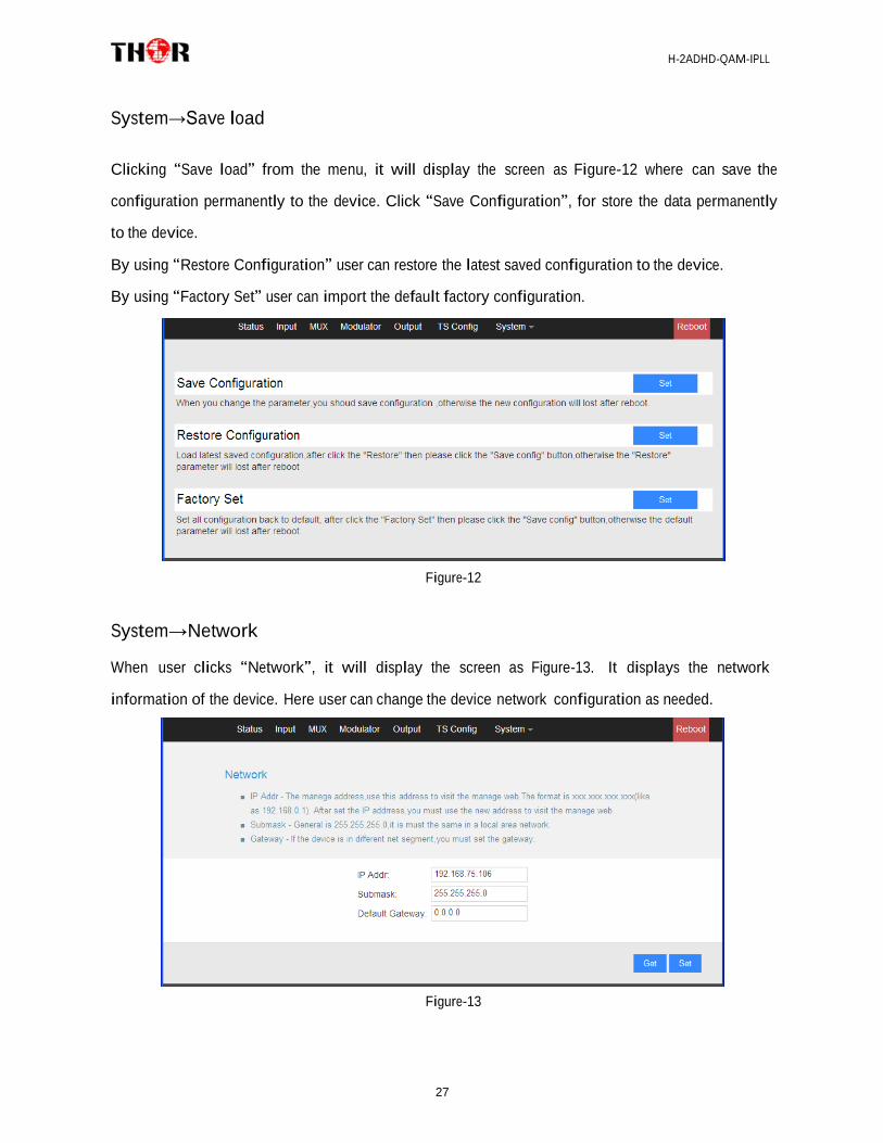
System→Save load Clicking “Save load” from the menu, it will display the screen as Figure-12 where can save the
configuration permanently to the device. Click “Save Configuration”, for store the data permanently
to the device.
By using “Restore Configuration” user can restore the latest saved configuration to the device.
By using “Factory Set” user can import the default factory configuration.
Figure-12
System→Network
When user clicks “Network”, it will display the screen as Figure-13. It displays the network
information of the device. Here user can change the device network configuration as needed.
Figure-13

H-2ADHD-QAM-IPLL
28
System→Change Password
When user clicks “Password”, it will display the password screen as Figure-14. Here user can
change the Username and Password for login to the device.
After putting the current and new Username and Password, click “Set” to save the configuration.
Figure-14
System→Firmware Click “Firmware” from the menu it will display the screen as Figure-15. Here user can update the
device by using the update file.
Click “Browse” to find the path of the device update file for this device then click “Update” to
update the device.
After updating the device, user needs to restart the device by using Reboot option.
Browse Button
Figure-15

H-2ADHD-QAM-IPLL
29
Chapter 5 Operation of Closed Caption (CC)
Closed Caption, hereinafter referred to as the CC. This unit has analog CC 608 only.
CC is from CVBS source output from IRD or STB etc. Connecting the CVBS cable to the CC port at
the rear panel (as shown in below image), CC can be mixed with A/V inputs to generate programs
with CC.
CC wiring diagram
CC switch in Web based NMS
CC switch On: Enable CC in
CC switch Off: Unable CC

H-2ADHD-QAM-IPLL
30
Chapter 6 Low Delay Setting
The H-2ADHD has a low delay option from encoding to STB decoding side. User can enable the low
delay function in the web-server NMS interface as shown below:
Click “Encoder Param” of “Channel 1” or “Channel 2” to set a low delay mode for each channel:
Low delay: Normal,
Mode 1, Mode 2,
Manual optional
There are 4 low delay modes: 1. Normal: to disable the low delay function.
2. Mode 1/Mode 2/Manual: to activate the low delay function.
DTS Delay, GOP B
frame, GOP P frame
are settable when
choose Low Delay
Mode: Manual.
The delay duration is based on the different combination of Video Format, Video Bit-rate, Low
delay Mode and the Resolution of signal source, which combine together to have a comprehensive
impact on the delay. Please refer to the below table for reference.
NOTE: The delay duration will also be impacted as the decoding performance of the STB side
change. Users need to apply a well-performed STB or other decoding terminals to achieve a low
delay
Internal Test Report of Time Delay
The values cover the progress from Encoding → Decoding
Decoding Terminal
Encoding Details Average Delay
(ms) Single Source
Bit Rate Mode
Resolution Low Delay
Encoding Type

H-2ADHD-QAM-IPLL
31
Interface Mode
DVB-C HD STB
HDMI
VBR
1080i@50
Mode 1 mpeg2 300 H.264 335
Mode 2 mpeg2 407.5
H.264 492.5
720p@50
Mode 1 mpeg2 230 H.264 285
Mode 2 mpeg2 382.5 H.264 395
DVB-C HD STB
YPbPr
VBR
1080i@50
Mode 1 mpeg2 282.5 H.264 395
Mode 2 mpeg2 397.5 H.264 450
720p@50
Mode 1 mpeg2 267.5 H.264 255
Mode 2 mpeg2 385 H.264 422.5
DVB-C HD STB
CVBS
VBR
576i@50
Mode 1 mpeg2 450 H.264 570
Mode 2 mpeg2 510 H.264 620
Decoding Terminal
Encoding Details
Average Delay (ms)
Single Source
Interface
Bit Rate Mode
Resolution Low
Delay Mode
Encoding Type
ATSC HD STB
HDMI
VBR
1080i@50
Mode 1 mpeg2 300
H.264 335
Mode 2 mpeg2 407.5 H.264 492.5
720p@50
Mode 1 mpeg2 230 H.264 285
Mode 2 mpeg2 382.5 H.264 395
ATSC HD STB
YPbPr
VBR
1080i@50
Mode 1 mpeg2 282.5 H.264 395
Mode 2 mpeg2 397.5
H.264 450
720p@50
Mode 1 mpeg2 267.5 H.264 255
Mode 2 mpeg2 385
H.264 422.5
ATSC-T HD STB
CVBS
VBR
576i@50
Mode 1 mpeg2 470
H.264 515
Mode 2 mpeg2 540 H.264 570
480i@60
Mode 1 mpeg2 460
H.264 500
Mode 2 mpeg2 510 H.264 550

H-2ADHD-QAM-IPLL
32
Chapter 7 Troubleshooting
THOR’s ISO9001 quality assurance system has been approved by the CQC organization. We
guarantee the products’ quality, reliability and stability. All THOR products haven passed all
testing and manual inspections before they are shipped out. The testing and inspection
scheme already covers all the Optical, Electronic and Mechanical criteria which have been
published by THOR. To prevent a potential hazard, please strictly follow the operation
conditions.
Prevention Measures
Installing the device in a place where the environmental temperature is between 0 to
45 °C
Making sure the unit has plenty of ventilation for the heat-sink on the rear panel; and
other heat-sink bores if necessary
Checking the AC input within the power supply and ensure it is working, the
connection is correctly installed before switching on device
Checking the RF output levels to stay within a tolerable range, if it is necessary
Checking all signal cables have been properly connected
Frequently switching on/off device is prohibited; the interval between every switching
on/off must be greater than 10 seconds.
Conditions needed to unplug power cord
Power cord or socket damage.
Any liquid that got into the device.
Any stuff that could cause a circuit short
Device in damp environment
Device has suffered from physical damage; i.e. it fell off a rack.
Longtime idle.
After switching on and restoring to factory setting, device still won’t work properly.
Maintenance needed on device

H-2ADHD-QAM-IPLL
33
ATSC Off-Air US Television Channels Center Frequency (MHz ) Chart
ATSC - US Television Channels (MHz)
Channel MHz Center Frequency
Channel
MHz Center Frequency
Channel
MHz Center Frequency
2
57
27
551
52
701
3
63
28
557
53
707
4
69
29
863
54
713
5
79
30
569
55
719
6
85
31
575
56
725
7
177
32
581
57
731
8
183
33
587
58
737
9
189
34
593
59
743
10
195
35
599
60
749
11
201
36
605
61
755
12
207
37
611
62
761
13
213
38
617
63
767
14
473
39
623
64
773
15
479
40
629
65
779
16
485
41
635
66
785
17
491
42
641
67
791
18
497
43
647
68
797
19
503
44
653
69
803
20
509
45
659
21
515
46
665
22
521
47
671
23
527
48
677
24
533
49
683
25
539
50
689
26
545
51
695
H-2ADHD-QAM-IPLL
34
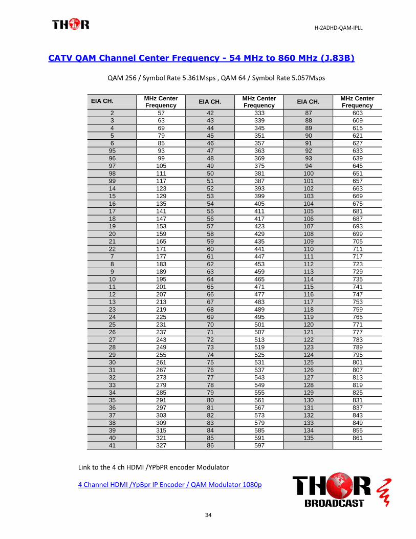
CATV QAM Channel Center Frequency - 54 MHz to 860 MHz (J.83B)
EIA CH. MHz Center Frequency
EIA CH. MHz Center Frequency
EIA CH. MHz Center Frequency
2 57 42 333 87 603
3 63 43 339 88 609
4 69 44 345 89 615
5 79 45 351 90 621
6 85 46 357 91 627
95 93 47 363 92 633
96 99 48 369 93 639
97 105 49 375 94 645
98 111 50 381 100 651
99 117 51 387 101 657
14 123 52 393 102 663
15 129 53 399 103 669
16 135 54 405 104 675
17 141 55 411 105 681
18 147 56 417 106 687
19 153 57 423 107 693
20 159 58 429 108 699
21 165 59 435 109 705
22 171 60 441 110 711
7 177 61 447 111 717
8 183 62 453 112 723
9 189 63 459 113 729
10 195 64 465 114 735
11 201 65 471 115 741
12 207 66 477 116 747
13 213 67 483 117 753
23 219 68 489 118 759
24 225 69 495 119 765
25 231 70 501 120 771
26 237 71 507 121 777
27 243 72 513 122 783
28 249 73 519 123 789
29 255 74 525 124 795
30 261 75 531 125 801
31 267 76 537 126 807
32 273 77 543 127 813
33 279 78 549 128 819
34 285 79 555 129 825
35 291 80 561 130 831
36 297 81 567 131 837
37 303 82 573 132 843
38 309 83 579 133 849
39 315 84 585 134 855
40 321 85 591 135 861
41 327 86 597
Link to the 4 ch HDMI /YPbPR encoder Modulator
4 Channel HDMI /YpBpr IP Encoder / QAM Modulator 1080p
QAM 256 / Symbol Rate 5.361Msps , QAM 64 / Symbol Rate 5.057Msps

H-2ADHD-QAM-IPLL
35
THOR BROADCAST
LOS ANGELES CA
1-800-521-8467