Embed Size (px)
Citation preview
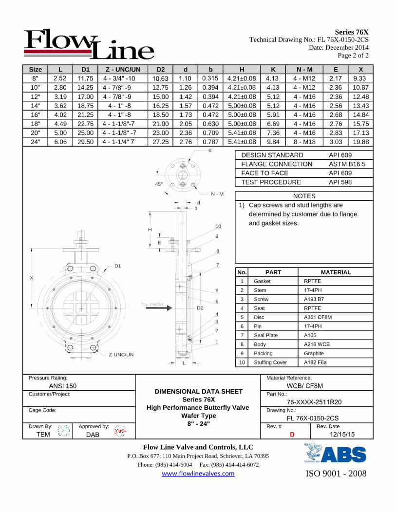
Series 76XTechnical Drawing No.: FL 76X-0150-2CS
Date: December 2014
Page 2 of 2
Size L D1 Z - UNC/UN D2 d b H K N - M E X
10" 2.80 14.25 4 - 7/8" -9 12.75 1.26 0.394 4.21±0.08 4.13 4 - M12 2.36 10.87
12" 3.19 17.00 4 - 7/8" -9 15.00 1.42 0.394 4.21±0.08 5.12 4 - M16 2.36 12.48
14" 3.62 18.75 4 - 1" -8 16.25 1.57 0.472 5.00±0.08 5.12 4 - M16 2.56 13.43
16" 4.02 21.25 4 - 1" -8 18.50 1.73 0.472 5.00±0.08 5.91 4 - M16 2.68 14.84
18" 4.49 22.75 4 - 1-1/8"-7 21.00 2.05 0.630 5.00±0.08 6.69 4 - M16 2.76 15.75
20" 5.00 25.00 4 - 1-1/8" -7 23.00 2.36 0.709 5.41±0.08 7.36 4 - M16 2.83 17.13
24" 6.06 29.50 4 - 1-1/4" 7 27.25 2.76 0.787 5.41±0.08 9.84 8 - M18 3.03 19.88
DESIGN STANDARD API 609
FLANGE CONNECTION ASTM B16.5
FACE TO FACE API 609
TEST PROCEDURE API 598
NOTES
1) Cap screws and stud lengths are
determined by customer due to flange
and gasket sizes.
No. PART MATERIAL
1 Gasket RPTFE
2 Stem 17-4PH
3 Screw A193 B7
4 Seat RPTFE
5 Disc A351 CF8M
6 Pin 17-4PH
7 Seal Plate A105
8 Body A216 WCB
9 Packing Graphite
10 Stuffing Cover A182 F6a
Pressure Rating: Material Reference:
ANSI 150 WCB/ CF8MCustomer/Project: Part No.:
76-XXXX-2511R20Cage Code:
DIMENSIONAL DATA SHEET
Series 76XHigh Performance Butterfly Valve
Wafer Type
8" - 24"
Drawing No.:
FL 76X-0150-2CSDrawn By: Approved by: Rev. # Rev. Date
TEM DAB D 12/15/15
Flow Line Valve and Controls, LLC
P.O. Box 677; 110 Main Project Road, Schriever, LA 70395
Phone: (985) 414-6004 Fax: (985) 414-414-6072
www.flowlinevalves.com ISO 9001 - 2008
E
H
Z-UNC/UN
D1
X
D2
45°
K
N - M
1
2
3
4
5
6
7
8
9
10
bd
L
8" 2.52 11.75 4 - 3/4" -10 10.63 1.10 0.315 4.21±0.08 4.13 4 - M12 2.17 9.33