Embed Size (px)
Citation preview

3.000.1
COILS FOR SOLENOID OPERATED VALVESStandard Coils and Proportional Valve Coils ........... 3.200.1Series E Water/Weather Resistant Coils .................. 3.400.1
Electronic Controls Introduction Electro-Hydraulic Control Technology 3.420.1DIN Coil-Mount Controllers 0–5 VDC, 10K Pot or 0–20 mA Input ........................... 3.421.1 0–10 VDC Input ........................................................... 3.422.1 4–20 mA Input ............................................................. 3.423.1 10K Pot or 0–5 VDC Input—Economy Version ............ 3.424.1 Soft Shift—12 or 24 VDC Input ................................... 3.425.1Remote-Mount PCB (Board Only) Controllers 0–5 VDC, 10K Pot or 0–20 mA Input ........................... 3.426.1 0–10 VDC Input ........................................................... 3.427.1Remote-Mount Metal Box Controllers 0–10 VDC Input ........................................................... 3.431.1 4–20 mA Input ............................................................. 3.432.1 PWM (Pulse Train) Input ............................................. 3.433.1DIN Rail-Mount Controllers 0–5 VDC, 10K Pot or 0–20 mA Input ........................... 3.434.1 0–10 VDC Input ........................................................... 3.435.1 4–20 mA Input ............................................................. 3.436.1 PWM (Pulse Train) Input ............................................. 3.437.1Dual Solenoid Driver, Multifunction Potted in Metal Box, 0–5 VDC, ±5 VDC, 0–10 VDC, 0–20 mA, ±20 mA Input ............................ 3.438.1Appendix Setup Instructions, Glossary of Terms ........................ 3.439.1 Electronics in Mobile Equipment ................................. 3.440.1EVDR Programmable Electronic Valve Driver .......... 3.451.1
ELECTRONIC CONTROLS FOR PROPORTIONAL VALVES
Coils & Electronic Controls
ELECTRONIC VEHICLE CONTROLSElectronic Control Units ECU-ML Machine Controller with 72 inputs ................ 3.501.1 ECU-MM Machine Controller with 44 inputs ............... 3.502.1 ECU-MS Machine Controller with 25 inputs ................ 3.503.1 70-Pin Electrical Connectors for ECU-Mx ................... 3.504.1 ECU Technical Reference Information ........................ 3.520.1Operator Input Devices Joystick, Single-Axis, EJS1Ax ..................................... 3.551.1 Joystick, Dual-Axis, EJS2Ax ....................................... 3.552.1 Shifter, Column-Mount, ESHFNR ................................ 3.554.1 Hand Control Unit, 4000934, 4000935 ........................ 3.555.1 Proportional Roller, ERLxx .......................................... 3.556.1 Foot Pedal, ETHFC1 ................................................... 3.557.1Switches Pressure Switches, EWP ............................................ 3.601.1 Proximity Switch, EWA5 .............................................. 3.603.1 Rocker Switches, ESWRK-xxx .................................... 3.604.1Sensors Analog Pressure Sensor, ERPxxx-5 ........................... 3.651.1 PWM Pressure Sensor, ERPxxx-P ............................. 3.652.1 Thermistor Temperature Sensor, ERT ......................... 3.653.1 Ground Speed Radar Sensor, ERRD59-12 ................ 3.654.1 Directional Speed Sensor, ERS1 ................................ 3.655.1 Variable Reluctance Speed Sensor, ERS5K ............... 3.656.1 Rotary Position Sensor, Med.-Duty, ERRxxxM-P ........ 3.657.1 Rotary Position Sensor, Heavy-Duty, ERRxxxH .......... 3.658.1Displays, Video LCD Display, 240 x 64, Model ELD-01 ........................ 3.701.1 LCD Display, 320 x 240, Model ELD-02 ...................... 3.702.1 LCD Display, 320 x 240, Model ELD-05 ...................... 3.705.1 Gauges, Digital In, Analog-Readout, Model EGAxD ... 3.712.1 Closed-Circuit Video System, Model CCV .................. 3.716.1Lights Heavy Duty Wide-Flood Work Lights ........................... 3.801.1
®HYDRAFORCE
HYDRAFORCE.com®

INTRODUCTION Electro-Hydraulic Control Technology ........................3.420.1
DIN COIL-MOUNT CONTROLLERS 0–5 VDC, 10K Pot or 0–20 mA Input .........................3.421.1 0–10 VDC Input .........................................................3.422.1 4–20 mA Input ...........................................................3.423.1 10K Pot or 0–5 VDC Input—Economy Version ..........3.424.1 Soft Shift—12 or 24 VDC Input ..................................3.425.1
REMOTE-MOUNT PCB CONTROLLERS 0–5 VDC, 10K Pot or 0–20 mA Input .........................3.426.1 0–10 VDC Input .........................................................3.427.1
REMOTE-MOUNT METAL BOX CONTROLLERS 0–10 VDC Input .........................................................3.431.1 4–20 mA Input ...........................................................3.432.1 PWM (Pulse Train) Input ............................................3.433.1
DIN RAIL-MOUNT CONTROLLERS 0–5 VDC, 10K Pot or 0–20 mA Input .........................3.434.1 0–10 VDC Input .........................................................3.435.1 4–20 mA Input ...........................................................3.436.1 PWM (Pulse Train) Input ............................................3.437.1
DUAL SOLENOID DRIVER Multifunction, Potted in Metal Box ..............................3.438.1
APPENDIX Setup Instructions ......................................................3.439.1 Glossary of Terms ......................................................3.439.2 Electronics in the Mobile Equipment Industries .........3.440.1
*NEW* EVDR SERIES UNIVERSAL-INPUT DRIVERS Valve Coil Plug-In Type, or Box Type for Separate Mounting. Multiple I/O Capability. See EVDR Selection Guide .......................................3.450.1
Table of Contents
CONTENTS
Introduction
Electronic Control
Electronic control in mobile equipment can consist of the following:
Operator Inputs: These inputs can be defi ned as the user interface, and can consist of joysticks, potentiometers, operator panels, or other input devices.
Feedback Inputs: These inputs can be defi ned as the machine interface, and can consist of pressure transducers, temperature sensors, fl ow sensors, velocity sensors or RPM sensors. When feedback inputs are used the system is described as “closed loop.”
Controller or ECU: This is the brains of the electronic control. It processes the inputs and converts them into a defi ned output to the hydraulic system. The controller also can have the ability to receive feedback inputs from machine sensors and attenuate its outputs accordingly. The controller can be factory-programmed or have the ability to be user-program-mable to meet the specifi c needs of the application.
Outputs: Outputs can be on/off voltage signals or proportional PWM signals to control the hydraulic valving.
Communications: The controller can have the ability to engage in two-way communications with a bus system (for example: communication between the ECU and a display, or output signal to an input device).
ECU—Electronic Control Unit
ECU’s were developed to replace the older “sequential relay circuits,” that were used for machine control. The ECU works by measuring its inputs and depending on their state, switching its outputs On or Off. The user enters setup instructions, usually via software, that will produce the desired results. Because many of the controller’s functions are user-program-mable, an ECU has the versatility to be fi eld-modifi ed for changing applications or conditions.
Some ECU’s have the capability to convert analog inputs, process them digitally, and produce analog outputs. ECUs that do not have built-in converters require separate analog-to-digital converters to convert the input.
Analog
An analog signal is an AC or DC voltage or current, or resis-tive signal that varies smoothly and continuously. In an analog system, a physical variable is represented by a proportional voltage that varies in correspondence with the physical variable. Electronic circuits that process analog signals are called linear circuits.
An example of an analog device is a traditional-style clock that has hour and minute sweep hands that rotate around the dial. As an input, an analog signal can provide infi nite resolution due to its wide frequency range.
ELECTRO-HYDRAULIC CONTROL
3.420.1
ELECTRONIC CONTROLS
HYDRAFORCE.com®

3.420.2
Electro-Hydraulic Control Technology
ELECTRO-HYDRAULIC CONTROL (cont’d)
Digital
Digital signals vary in discrete (discontinuous) values to represent information for input. A digital signal is normally in the form of a series of pulses that rapidly change from one distinct, fi xed voltage level to another.
An example of a digital device is a clock that displays the time in actual numerals that change in one-numeral increments. As an input, the resolution is dependent on the number of bits of information processed or available to the controller. In digital systems, physical variables are represented by numerical values using the binary (base 2) number system.
Electronic Control Platforms
Some of the different forms that mobile electronics can take are described in the chart shown on this page. There is an increasing complexity and cost as the controllers move from single-function analog controls to complete complex digital control systems.
Digital vehicle controllers offer a high level of sophistica-tion by executing a programmed sequence of functions that constantly control all motion parameters.
Inputs Outputs
ECUPersonality Features Needed
User ProgrammableFactory SetPackaging
CostOther
Control Signal(User Interface)
JoystickPotentiometer
Operator PanelOther
Feedback InputsSensors
CommunicationsFieldbus, Wireless
Hydraulic System
On/Off
Proportional
Power
Diagnostic
Electronic Control Technology Platforms for the Mobile Equipment Market
Vehicle Control Systems
Vehicle Control SubsystemsTransmission Controller
Microprocessor
Digital Signal Processor
PID Controller
Motor Controller
Pump Controller
Closed Loop Flow Controller
Fan Drive (with Sensor Input)
Controller with Position Feedback(Servo Mechanism)
Digital Control Products
Analog Control Products
On/Off Functions
Proportional Valve
Controllers
Soft Shift
Soft Shift/Hold
Low Cost Fan Drive
Converter
Incr
easi
ng
Co
mp
lexi
ty a
nd
Val
ue
®HYDRAFORCE
HYDRAFORCE.com®

DESCRIPTION 0–5 VDC, 10K Pot or 0–20 mA InputA convenient, plug-mounted control amplifier for controlling HydraForce proportional valves that have solenoids with DIN 43650A/ISO 4400 electrical connectors.
OPERATIONThis control module uses closed-loop current control with superimposed dither to sup-ply a proportional valve solenoid with a proportional control signal. The input signal to this controller can be from a 10K potentiometer, 0–5 VDC, 0–20 mA, or from other pre-set levels.
FEATURES•Mounts directly to solenoid coils with DIN 43650A connectors.•IP65 weather resistant when used with base gasket (supplied). •Adjustments accessible with a removable cover.•One unit covers supply voltages from 9 to 32 VDC.•No internal fuses; circuit limits current electronically.•Short circuit proof and reverse polarity protected.•Connector can be disconnected from coil when powered.•Maximum current adjustment does not affect minimum current setting.•Independent ramp adjustments and internal supply for potentiometer.•Dither frequency and amplitude are adjustable for maximum valve performance.
RATINGSSupplyVoltage:9–32 VDC
Coil rating must be matched with supply voltage: RCOIL ≤ (VSUPPLY – 1.5 V) / I-Max.ControlInputSignalOptions: 10K external potentiometer (accepts 5K to 50K pots),
or 0–5 VDC signal, or 0–20 mA current signal (see connection diagrams)InputResistance: Voltage Control: 125K Ohms; Current Control: 50 OhmsOutputCurrent: up to 2000 mA (see ordering info.)MinimumCurrentRange: 0–500 mA (adjustable; see ordering info.)MaximumCurrentRange: 600–2000 mA (adjustable; see ordering info)RampUpand/orDown: 0.01–5.0 seconds (independently adjustable)DitherFrequency: 70–350 Hz (adjustable)DitherAmplitude: 0–10% of maximum current (adjustable)OperatingConditions:–40° to 85°C; 0 to 85% relative humidityEnvironmentalProtection: IP65 with cover and base gasket installed
3.421.1
GENERALSPECIFICATIONSPlugHousing:PolyamidePlugLid:PolycarbonateWeight: 30 g (1.06 oz.) without cableConnections: Mounted cable
with unterminated wires provided; Length: approximately 2 meters (79")
Proportional Valve Controller—DIN Coil Mount—
SCHEMATIC
STEP-DOWNCONVERTERVPS TO 5.5 V
STEP-UPDC/DC
CONVERTER
SO
LEN
OID
OU
TP
UT
DITHERAMPLITUDE
ACTIVEREVERSE POLARITY
PROTECTION
DITHERGENERATOR
CURRENT SENSING AND
SHORT CIRCUITPROTECTION
VPS
POWERGND
PO
TE
NT
IOM
ET
ER
INP
UT
+
–
S2
S1
RM
I-MAX.
RAMP UP RAMP DOWN
RMAX.
ERRORAMPLIFIER
+–
RDA
RMIN.
I-MIN.
+5 V
RD
DITHER FREQUENCY
RDITHER
INDEPENDENTRAMP CONTROL
FUNCTION
VOLTAGETO
HIGH FREQUENCYPWM
CONVERTER
SIGNAL GND
CURRENT IN(0-20 mA)
VOLTAGE IN(0-5 VDC)
VOLTAGEREFERENCEGENERATOR
+5 VREFERENCE
+12 V–12 V
+5 V
(9-32 VDC)
ELECTRONIC CONTROLS
HYDRAFORCE.com®

3.421.2
DIMENSIONS
TOORDER
PartNumber Output I-Min.Setting I-Max.Setting CableLength7114950 2000 mA Max. 0 to 500 mA 600 to 2000 mA 2 meters
4000161 1200 mA Max. 0 to 150 mA 400 to 1200 mA 2 meters
CONNECTIONS
SuppliedbyUser
10KPotentiometer(Pot.)Control
WireColor
Red
Black
Blue
White
Green
Brown
(+) Power
(–) Power
10K Pot.
Not Used
SuppliedbyUser
0to20mAControl
WireColor
0to5VDCControl
Red
Black
Blue
White
Green
Brown
(+) Power
(–) Power
Not Used
Not Used
(–) 0–20mA
(+) 0–20mA
SuppliedbyUser WireColor
Red
Black
Blue
White
Green
Brown
(+) Power
(–) Power
(–) 0–5V
Not Used
(+) 0–5V
Not Used(+) Pot.
(–) Pot.
ForEither0–20mAor0–5VDCControl:Turn ramp screws fully counterclockwise to eliminate ramping.Use I-Min. screw to set minimum speed with minimum control input.Use I-Max. screw to set maximum speed with 100% of control input.
Red(+) Power Supply
ADJUSTMENTSDETAIL
Black(–) Power Supply
Blue0–20 mA Input
WhitePotentiometer PowerGreen0–5 VDC Input
BrownInput Ground
MILLIMETREINCH
1.3434
1.5038
.225.5
1.3434
M3
3.3685
79APPROX.
AdjustmentsUnder Cover.See Detail.
2 M
MinimumCurrent
DitherAmplitude
FallingRamp
RisingRamp
DitherFrequency
MaximumCurrent
ForCompleteSet-UpInstructions,seepage3.439.1
0–5 VDC, 10K Pot or 0–20 mA Input
®HYDRAFORCE
HYDRAFORCE.com®

DESCRIPTION 0–10 VDC InputA convenient, plug-mounted control amplifier for controlling HydraForce proportional valves that have solenoids with DIN 43650A/ISO 4400 electrical connectors.
OPERATIONThis control module uses closed-loop current control with superimposed dither to supply a proportional valve solenoid with a proportional control signal. The input signal to this controller can be from a 0–10 VDC source.
FEATURES•Mounts directly to solenoid coils with DIN 43650A connectors.•IP65 weather resistant when used with base gasket (supplied). •Adjustments accessible with a removable cover.•One unit covers supply voltages from 9 to 32 VDC.•No internal fuses; circuit limits current electronically.•Short circuit proof and reverse polarity protected.•Can be disconnected from coil when powered.•Maximum current adjustment does not affect minimum current setting.•Independent ramp adjustments and internal supply for potentiometer.•Dither frequency and amplitude are adjustable for maximum valve performance.
RATINGSSupplyVoltage:9–32 VDC
Coil rating must be matched with supply voltage: RCOIL ≤ (VSUPPLY – 1.5 V) / I-Max.ControlInputSignal: 0–10 VDCInputResistance: 225K OhmsOutputCurrent: up to 2000 mA (see ordering info.)MinimumCurrentRange: 0–500 mA (adjustable; see ordering info.)MaximumCurrentRange: 600–2000 mA (adjustable; see ordering info.)RampUpand/orDown: 0.01–5.0 seconds (independently adjustable)DitherFrequency: 70–350 Hz (adjustable)DitherAmplitude: 0–10% of maximum current (adjustable)OperatingConditions:–40° to 85°C; 0 to 85% relative humidityEnvironmentalProtection: IP65 with cover and base gasket installed
3.422.1
GENERALSPECIFICATIONSPlugHousing:PolyamidePlugLid:PolycarbonateWeight: 30 g (1.06 oz.) without cableConnections: Mounted cable
with unterminated wires provided; Length: approximately 2 meters (79")
Proportional Valve Controller—DIN Coil Mount—
SCHEMATIC
STEP-DOWNCONVERTERVPS TO 5.5 V
STEP-UPDC/DC
CONVERTER
SO
LEN
OID
OU
TP
UT
DITHERAMPLITUDE
ACTIVEREVERSE POLARITY
PROTECTION
DITHERGENERATOR
CURRENT SENSING AND
SHORT CIRCUITPROTECTION
VPS
POWERGND
+
–
S2
S1
RM
I-MAX.
RAMP UP RAMP DOWN
RMAX.
ERRORAMPLIFIER
+–
RDA
RMIN.
I-MIN.
+5 V
RD
DITHER FREQUENCY
RDITHER
INDEPENDENTRAMP CONTROL
FUNCTION
VOLTAGETO
HIGH FREQUENCYPWM
CONVERTER
SIGNAL GND
NOT USED
VOLTAGE IN(0-10 VDC)
NOT USED
+12 V–12 V
+5 V
(9-32 VDC)
ELECTRONIC CONTROLS
HYDRAFORCE.com®

3.422.2
DIMENSIONS
TOORDER
PartNumber Output I-Min.Setting I-Max.Setting CableLength4000070 2000 mA Max. 0 to 500 mA 600 to 2000 mA 2 meters
4000165 1200 mA Max. 0 to 150 mA 400 to 1200 mA 2 meters
CONNECTIONS
0to10VDCControl
SuppliedbyUser WireColor
Red
Black
Blue
White
Green
Brown
(+) Power
(–) Power
(–) 0–10V
Not Used
(+) 0–10V
Not Used
BasicSetup:Turn ramp screws fully counterclockwise to eliminate ramping.Use I-Min. screw to set minimum speed with minimum control input.Use I-Max. screw to set maximum speed with 100% of control input.
Red(+) Power Supply
ADJUSTMENTSDETAIL
Black(–) Power SupplyBlueNot Used
WhiteNot UsedGreen0–10 VDC Input
BrownInput Ground
MILLIMETREINCH
1.3434
1.5038
.225.5
1.3434
M3
3.3685
79APPROX.
AdjustmentsUnder Cover.See Detail.
2 M
MinimumCurrent
DitherAmplitude
FallingRamp
RisingRamp
DitherFrequency
MaximumCurrent
ForCompleteSet-UpInstructions,seepage3.439.1
0–10 VDC Input
®HYDRAFORCE
HYDRAFORCE.com®

DESCRIPTION 4–20 mA InputA convenient, plug-mounted control amplifi er for controlling HydraForce proportional valves that have solenoids with DIN 43650A/ISO 4400 electrical connectors.
OPERATIONThis control module uses closed-loop current control with superimposed dither to supply a proportional valve solenoid with a proportional control signal. This control-ler will accept a 4–20 mA input signal from a programmable logic controller (PLC) or other control systems.
FEATURES• Mounts directly to solenoid coils with DIN 43650A connectors.• IP65 weather resistant when used with base gasket (supplied). • Adjustments accessible with a removable cover.• One unit covers supply voltages from 9 to 32 VDC.• No internal fuses; circuit limits current electronically.• Short circuit proof and reverse polarity protected.• Connector can be disconnected from coil when powered.• Maximum current adjustment does not affect minimum current setting.• Independent ramp adjustments.• Dither frequency and amplitude are adjustable for maximum valve performance.
RATINGSSupply Voltage: 9–32 VDC
Coil rating must be matched with supply voltage: RCOIL ≤ (VSUPPLY – 1.5 V) / I-Max.Control Input Signal Options: 4–20 mA current signalInput Resistance: 50 OhmsOutput Current: 1200 mAMinimum Current Range: 0–150 mA, adjustableMaximum Current Range: 400–1200 mA, adjustableRamp Up and/or Down: 0.01–5.0 seconds, independently adjustableDither Frequency: 70–350 Hz, adjustableDither Amplitude: 0–10% of maximum current, adjustableOperating Conditions: –40° to 85°C; 0 to 85% relative humidityEnvironmental Protection: IP65 with cover and base gasket installed
3.423.1
GENERAL SPECIFICATIONSPlug Housing: PolyamidePlug Lid: PolycarbonateWeight: 30 g (1.06 oz.) without cableConnections: Mounted cable
with unterminated wires provided; Length: approximately 2 meters (79")
Proportional Valve Controller—DIN Coil Mount—
SCHEMATIC
STEP-DOWNCONVERTERVPS TO 5.5 V
STEP-UPDC/DC
CONVERTER
SO
LEN
OID
OU
TP
UT
DITHERAMPLITUDE
ACTIVEREVERSE POLARITY
PROTECTION
DITHERGENERATOR
CURRENT SENSING AND
SHORT CIRCUITPROTECTION
VPS
POWERGND
CU
RR
EN
T L
OO
P T
RA
NS
MIT
TE
R
+
–
S2
S1
RM
I-MAX.
RAMP UP RAMP DOWN
RMAX.
ERRORAMPLIFIER
+–
RDA
RMIN.
I-MIN.
+5 V
RD
DITHER FREQUENCY
RDITHER
INDEPENDENTRAMP CONTROL
FUNCTION
VOLTAGETO
HIGH FREQUENCYPWM
CONVERTER
SIGNAL GND
CURRENT IN(4-20 mA)
+12 V–12 V
+5 V
(9-32 VDC)
ELECTRONIC CONTROLS
HYDRAFORCE.com®

3.423.2
DIMENSIONS
TO ORDER
Part Number Output I-Min. Setting I-Max. Setting Cable Length4000169 1200 mA Max. 0 to 150 mA 400 to 1200 mA 2 meters
CONNECTIONS
Supplied by User
4 to 20 mA Control
Wire Color
Red
Black
White
Green
(+) Power
(–) Power
(–) 4–20mA
(+) 4–20mA
Basic Setup:Turn ramp screws fully counterclockwise to eliminate ramping.Use I-Min. screw to set minimum speed with minimum control input.Use I-Max. screw to set maximum speed with 100% of control input.
Red(+) Power Supply
ADJUSTMENTS DETAIL
Black(–) Power Supply
White(+) 4-20 mA InputGreenSignal Ground
MILLIMETREINCH
1.3434
1.5038
.225.5
1.3434
M3
3.3685
79APPROX.
AdjustmentsUnder Cover.See Detail.
2 M
MinimumCurrent
DitherAmplitude
RampDown
Ramp Up
DitherFrequency
MaximumCurrent
For Complete Set-Up Instructions, see page 3.439.1
4–20 mA Input
®HYDRAFORCE
HYDRAFORCE.com®

DESCRIPTION 10K Pot or 0–5 VDC Input—Economy VersionA convenient, plug-mounted control amplifier for controlling HydraForce proportional valves that have solenoids with DIN 43650A/ISO 4400 electrical connectors.
OPERATIONThis control module supplies a proportional valve solenoid with a proportional control signal. The input signal to this controller can be from a 10K potentiometer or a 0–5 VDC source. This economy version has no ramp adjustments. Dither frequency and amplitude are factory pre-set.
FEATURES•Mounts directly to solenoid coils with DIN 43650A connectors.•IP65 weather resistant when used with base gasket (supplied). •Adjustments accessible with a removable cover.•One unit covers supply voltages from 9 to 32 VDC.•No internal fuses; circuit limits current electronically.•Short circuit proof and reverse polarity protected.•Connector can be disconnected from coil when powered.•Maximum current adjustment does not affect minimum current setting.•Internal supply for potentiometer.
RATINGSSupplyVoltage:9–32 VDC
Coil rating must be matched with supply voltage: RCOIL ≤ (VSUPPLY – 1.5 V) / I-Max.ControlInputSignalOptions: 10K external potentiometer (accepts 5K to 50K pots),
or 0–5 VDC current signal (see connection diagrams)InputResistance: 187K OhmsOutputCurrent: up to 2000 mA (see ordering info.)MinimumCurrentRange: 0–500 mA (adjustable)MaximumCurrentRange: 600–2000 mA (adjustable)InternalSupplyforSetpointPotentiometer: +5VDCDitherFrequency: 90 or 220 Hz (±10% of full scale) Preset at FactoryDitherAmplitude: 5% Preset at FactoryOperatingConditions:–40° to 85°C; 0 to 85% relative humidityEnvironmentalProtection: IP65 with cover and base gasket installed
3.424.1
GENERALSPECIFICATIONSPlugHousing:PolyamidePlugLid:PolycarbonateWeight: 30 g (1.06 oz.) without cableConnections: Mounted cable
with unterminated wires provided; Length: approximately 2 meters (79")
Proportional Valve Controller—DIN Coil Mount—
SCHEMATIC
LOW DROP OUT (LDO) VOLTAGE
REGULATOR
SO
LEN
OID
OU
TP
UT
ACTIVEREVERSE POLARITY
PROTECTION
DITHERGENERATOR
CURRENT SENSING AND
SHORT CIRCUITPROTECTION
VPS
POWERGND
PO
TE
NT
IOM
ET
ER
INP
UT
+
–
S2
S1
I-MAX.
RD
RMIN.RIN
RMAX.
ERRORAMPLIFIER
+–
RM
I-MIN.
+5V
VOLTAGETO
HIGH FREQUENCYPWM
CONVERTER
SIGNAL GND
VOLTAGE IN(0-5 VDC)
VOLTAGEREFERENCEGENERATOR
+5 VREFERENCE
(9-32 VDC)
ELECTRONIC CONTROLS
HYDRAFORCE.com®

3.424.2
DIMENSIONS
TOORDER
PartNumber DitherFreq. Output I-Min.Setting I-Max.Setting CableLength4000172 90 Hz 2000 mA 0 to 500 mA 600 to 2000 mA 2 meters
4000236 220 Hz 2000 mA 0 to 500 mA 600 to 2000 mA 2 meters
CONNECTIONS
SuppliedbyUser
10KPotentiometer(Pot.)Control
WireColor
Red
Black
White
Green
Brown
(+) Power
(–) Power
10K Pot.
0to5VDCControl
SuppliedbyUser WireColor
Red
Black
White
Green
Brown
(+) Power
(–) Power
(–) 0–5V
(+) 0–5V
Not Used(+) Pot.
(–) Pot.
Red(+) Power Supply
Black(–) Power Supply
WhitePotentiometer PowerGreen0–5 VDC Input
BrownInput Ground
MILLIMETREINCH
1.3434
1.5038
.225.5
1.3434
M3
3.3685
79APPROX.
AdjustmentsUnder Cover.See Detail.
2 M
ADJUSTMENTSDETAIL
MinimumCurrent
Maximum Current
ForCompleteSet-UpInstructions,seepage3.439.1
10K Pot or 0–5 VDC Input—Economy Version
®HYDRAFORCE
HYDRAFORCE.com®

DESCRIPTION Soft Shift—12 or 24 VDC InputA convenient, plug-mounted controller for HydraForce proportional valves that have solenoids with DIN 43650A/ISO 4400 electrical connectors.
OPERATIONThis controller uses the power supply voltage as the control signal. It has an adjust-able increasing ramp and an adjustable I-Max. setting. When power is applied to this controller, its output ramps up to maximum current in a time period that is adjustable within a factory set range. The ramp adjustment allows the user to defi ne the length of time required for the hydraulic valve to reach its maximum output. When electrical power is removed, the output of this controller immediately falls to zero.
FEATURES• Mounts directly to solenoid coils with DIN 43650A connectors.• IP65 weather resistant when used with base gasket (supplied). • Adjustments accessible with a removable cover.• One unit covers supply voltages from 9 to 32 VDC.• No internal fuses; circuit limits current electronically.• Short circuit proof.
RATINGSSupply Voltage: 9–32 VDC
Coil rating must be matched with supply voltage: RCOIL ≤ (VSUPPLY – 1.5 V) / I-Max.Output Current: 2 Amps Max.Ramp Adjustment: 0.01 to 5 secondsI-Max. Adjustment: 200–650 mA, or 900–2000 mADither Frequency: 300 Hz ±10% (fi xed)Dither Amplitude: 10% of rated maximum (fi xed)Operating Conditions: –40° to 85°C; 0 to 85% relative humidityEnvironmental Protection: IP65 with cover and base gasket installed
3.425.1
GENERAL SPECIFICATIONSPlug Housing: PolyamidePlug Lid: PolycarbonateWeight: 30 g (1.06 oz.) without cableConnections: Mounted cable
with unterminated wires provided; Length: approximately 2 meters (79")
Proportional Valve Controller—DIN Coil Mount—
SCHEMATIC
7.5 V (LDO)LOW DROP OUT
REGULATOR
SO
LEN
OID
OU
TP
UT
REVERSE POLARITYPROTECTION
TRANSIENTPROTECTION
CURRENT SENSING AND
SHORT CIRCUITPROTECTION
24 VPS +
–
S2
S1
D2
D1
ERRORAMPLIFIER
WAVEFORMGENERATOR
POWERUP
I-MAX.
RAMPTIME
+–
HIGH FREQUENCYPWM
MODULATOR
POWEROUTPUTSTAGE
(9-32 VDC)
ELECTRONIC CONTROLS
HYDRAFORCE.com®

3.425.2
DIMENSIONS
TO ORDER
Part Number I-Max. Setting Adjustable Ramp Time Cable Length4000072 900 to 2000 mA 0.01 to 5 seconds 2 meters
4000226 200 to 650 mA 0.01 to 5 seconds 2 meters
Adjustments:Ramp: Single Turn Potentiometer; CCW to increase ramp time.I-Max.: Single Turn Potentiometer; CW to increase I-Max.
Red(+) 12 or 24 VDC Power
Black(–) 12 or 24 VDC Power
MILLIMETREINCH
1.3434
1.5038
.225.5
1.3434
M3
3.3685
79APPROX.
Adjustments UnderCover. See Detail.
2 M
ADJUSTMENTS DETAIL
MaximumCurrent
Rising Ramp
Soft Shift—12 or 24 VDC Input
®HYDRAFORCE
HYDRAFORCE.com®

DESCRIPTION 0–5 VDC, 10K Pot or 0–20 mA InputA printed circuit board-style (PCB) control amplifier for controlling HydraForce proportional valves. Remote mounting in a protected enclosure is required.
OPERATIONThis control module uses closed-loop current control with superimposed dither to supply a proportional valve solenoid with a proportional control signal. The input signal to this controller can be from a 10K potentiometer, 0–5 VDC, 0–20 mA, or from other pre-set levels.
FEATURES•Adjustments and connections clearly labeled.• LED indication of output power level, input level and power on/off.•One unit covers supply voltages from 9 to 32 VDC.•No internal fuses; circuit limits current electronically.•Short circuit proof and reverse polarity protected.•Can be disconnected from coil when powered.•Maximum current adjustment does not affect minimum current setting.•Independent ramp adjustments and internal supply for potentiometer.• Filter eliminates electrical noise.•Dither frequency and amplitude are adjustable for maximum valve performance.
RATINGSSupplyVoltage:9–32 VDC
Coil rating must be matched with supply voltage: RCOIL ≤ (VSUPPLY – 1.5 V) / I-Max.ControlInputSignalOptions: 10K external potentiometer (accepts 5K to 50K pots),
or 0–5 VDC signal, or 0–20 mA current signal (see connection diagrams)InputResistance: Voltage: 250K Ohms; Current: 33 OhmsOutputCurrent: up to 2000 mA (see ordering info.)MinimumCurrentRange: 0–500 mA (adjustable; see ordering info.)MaximumCurrentRange: 600–2000 mA (adjustable; see ordering info.)RampUpand/orDown: 0.01–5.0 seconds (independently adjustable)DitherFrequency: 70–350 Hz (adjustable)DitherAmplitude: 0–10% of maximum current (adjustable)OperatingConditions:–40° to 85°C; 0 to 85% relative humidity
3.426.1
Proportional Valve Controller—PCB Only—
SCHEMATIC
STEP-DOWNCONVERTERVPS TO 5.5 V
STEP-UPDC/DC
CONVERTER
INPUT, OUTPUTAND
POWER SUPPLYINDICATORS
SO
LEN
OID
OU
TP
UT
DITHERAMPLITUDE
ACTIVEREVERSE POLARITY
PROTECTION
DITHERGENERATOR
CURRENT SENSING AND
SHORT CIRCUITPROTECTION
VPS
POWERGND
PO
TE
NT
IOM
ET
ER
INP
UT
+
–
S2
S1
RM
I-MAX.
RAMP UP RAMP DOWN
RMAX.
ERRORAMPLIFIER
LOWPASS
FILTER+–
RDA
RMIN.
I-MIN.
+5 V
RD
DITHER FREQUENCY
RDITHER
INDEPENDENTRAMP CONTROL
FUNCTION
VOLTAGETO
HIGH FREQUENCYPWM
CONVERTER
SIGNAL GND
CURRENT IN(0-20 mA)
ENABLE
VOLTAGE IN(0-5 VDC)
VOLTAGEREFERENCEGENERATOR
+5 VREFERENCE
+12 V–12 V
+5 V
(9-32 VDC)
CF
GENERALSPECIFICATIONSWeight:25 g (0.88 oz.)Connections: Screw terminals
for 16–30 AWG wire
CSAListing:CSA C22.2 No. 14-M91
ELECTRONIC CONTROLS
HYDRAFORCE.com®

3.426.2
DIMENSIONS
TOORDER
PartNumber Output I-Min.Setting I-Max.Setting4000046 2000 mA Max. 0 to 500 mA 600 to 2000 mA
4000194 1200 mA Max. 0 to 150 mA 400 to 1200 mA
CONNECTIONS
ForEither0–20mAor0–5VDCControl: Turn ramp screws fully counterclockwise to eliminate ramping. Use I-Min. screw to set minimum speed with minimum control input. Use I-Max. screw to set maximum speed with 100% of control input.
Mounting Holes (4)0.156 (3.90) Dia.for #6 size screws(not supplied)
(+) Power
ScrewTerminalConnectionsfor16–30AWGwire
(–) Power
+5V ReferenceVoltage InAnalog GroundCurrent In
Enable
Frame Ground(–) Solenoid
(+) Solenoid
Ramp Up(Rising Edge)
Ramp Down(Falling Edge)
Dither Level(Amplitude)Dither
Frequency
ZeroI-Min.
SpanI-Max.
AGND
IIN
ENABLE
FGND
SOL–
SOL+
VIN
TP3
L1
L2L3
R32
R31
R49
R50 R46TP7
TP6
TP9TP8
TP10
TP5
R48
TP
1
TP2
TP4REF
POW–
POW+
+5V
SetscrewAdjustments
2.5063.5
2.1053.3
2.5063.5
2.1053.3
MILLIMETREINCH
Note: When Enable is connected to (+) Power or left open, the unit is enabled. When Enable is connected to (–) Power, the unit will be disabled.
Input Level LEDBrightness increases asinput signal increases.
PowerOkay LED
Output Level LEDBrightness increases as
output amperage increases.
ForCompleteSet-UpInstructions,seepage3.439.1
0–5 VDC, 10K Pot or 0–20 mA Input
SuppliedbyUser
10KPotentiometer(Pot.)Control
ScrewTerminal
(+) Power
(–) Power
(+) 5V Reference
Voltage In
Analog Gnd.
Current In
Enable
Frame Gnd.
(–) Solenoid
(+) Solenoid
(+) Power
(–) Power
10K Pot.
(+) Pot.
(–) Pot.
Not Used
Enable
(–) Coil
(+) Coil
Frame Gnd.
SuppliedbyUser
0to20mAControl
ScrewTerminal
0to5VDCControl
(+) Power
(–) Power
Not Used
Not Used
(–) 0–20mA
(+) 0–20mA
Enable
(–) Coil
(+) Coil
Frame Gnd.
SuppliedbyUser ScrewTerminal
(+) Power
(–) Power
(+) 0–5V
Not Used
(–) 0–5V
Not Used
Enable
(–) Coil
(+) Coil
Frame Gnd.
(+) Power
(–) Power
(+) 5V Reference
Voltage In
Analog Gnd.
Current In
Enable
Frame Gnd.
(–) Solenoid
(+) Solenoid
(+) Power
(–) Power
(+) 5V Reference
Voltage In
Analog Gnd.
Current In
Enable
Frame Gnd.
(–) Solenoid
(+) Solenoid
®HYDRAFORCE
HYDRAFORCE.com®

DESCRIPTION 0–10 VDC InputA printed circuit board-style (PCB) control amplifier for controlling HydraForce proportional valves. Remote mounting in a protected enclosure is required.
OPERATIONThis control module uses closed-loop current control with superimposed dither to supply a proportional valve solenoid with a proportional control signal. The input signal to this controller can be from a 0–10 VDC source.
FEATURES•Adjustments and connections clearly labeled.• LED indication of output power level, input level and power on/off.•One unit covers supply voltages from 9 to 32 VDC.•No internal fuses; circuit limits current electronically.•Short circuit proof and reverse polarity protected.•Can be disconnected from coil when powered.•Maximum current adjustment does not affect minimum current setting.•Independent ramp adjustments.• Filter eliminates electrical noise.•Dither frequency and amplitude are adjustable for maximum valve performance.
RATINGSSupplyVoltage:9–32 VDC
Coil rating must be matched with supply voltage: RCOIL ≤ (VSUPPLY – 1.5 V) / I-Max.ControlInputSignal: 0–10 VDCInputResistance: 250K OhmsOutputCurrent: up to 2000 mA (see ordering info.)MinimumCurrentRange: 0–500 mA (adjustable)MaximumCurrentRange: 600–2000 mA (adjustable)RampUpand/orDown: 0.01–5.0 seconds (independently adjustable)DitherFrequency: 70–350 Hz (±10%)DitherAmplitude: 0–10% of maximum current (adjustable)OperatingConditions:–40° to 85°C; 0 to 85% relative humidity
3.427.1
Proportional Valve Controller—PCB Only—
SCHEMATIC
STEP-DOWNCONVERTERVPS TO 5.5 V
STEP-UPDC/DC
CONVERTER
INPUT, OUTPUTAND
POWER SUPPLYINDICATORS
SO
LEN
OID
OU
TP
UT
DITHERAMPLITUDE
ACTIVEREVERSE POLARITY
PROTECTION
DITHERGENERATOR
CURRENT SENSING AND
SHORT CIRCUITPROTECTION
VPS
POWERGND
+
–
S2
S1
RM
I-MAX.
RAMP UP RAMP DOWN
RMAX.
ERRORAMPLIFIER
LOWPASS
FILTER+–
RDA
RMIN.
I-MIN.
+5 V
RD
DITHER FREQUENCY
RDITHER
INDEPENDENTRAMP CONTROL
FUNCTION
VOLTAGETO
HIGH FREQUENCYPWM
CONVERTER
ANALOG GND
NOT USED
ENABLE
VOLTAGE IN(0-10 VDC)
NOT USED
+12 V–12 V
+5 V
(9-32 VDC)
CF
GENERALSPECIFICATIONSWeight:25 g (0.88 oz.)Connections: Screw terminals
for 16–30 AWG wire
CSAListing:CSA C22.2 No. 14-M91
ELECTRONIC CONTROLS
HYDRAFORCE.com®

3.427.2
DIMENSIONS
TOORDER
PartNumber Output I-Min.Setting I-Max.Setting4000141 2000 mA Max. 0 to 500 mA 600 to 2000 mA
CONNECTIONS
BasicSetup: Controller is shipped with ramp trim pots fully counterclockwise to eliminate ramping. Use I-Min. screw to set minimum speed with minimum control input. Use I-Max. screw to set maximum speed with 100% of control input.
Mounting Holes (4)0.156 (3.90) Dia.for #6 size screws(not supplied)
(+) Power
ScrewTerminalConnectionsfor16–30AWGwire
(–) Power
Not UsedVoltage InAnalog GroundNot Used
Enable
Note: When Enable is connected to (+) Power or left open, the unit is enabled. When Enable is connected to (–) Power, the unit will be disabled.Frame Ground
(–) Solenoid
(+) Solenoid
Input Level LEDBrightness increases asinput signal increases.
PowerOkay LED
Output Level LEDBrightness increases as
output amperage increases.
Ramp Up(Rising Edge)
Ramp Down(Falling Edge)
Dither Level(Amplitude)Dither
Frequency
ZeroI-Min.
SpanI-Max. AGND
IIN
ENABLE
FGND
SOL–
SOL+
VIN
TP3
L1
L2L3
R32
R31
R49
R50 R46TP7
TP6
TP9TP8
TP10
TP5
R48
TP
1
TP2
TP4REF
POW–
POW+
+5V
SetscrewAdjustments
2.5063.5
2.1053.3
2.5063.5
2.1053.3
MILLIMETREINCH
ForCompleteSet-UpInstructions,seepage3.439.1
0–10 VDC Input
0to10VDCControl
SuppliedbyUser ScrewTerminal
(+) Power
(–) Power
(+) 0–10V
Not Used
(–) 0–10V
Not Used
Enable
(–) Coil
(+) Coil
Frame Gnd.
(+) Power
(–) Power
(+) 5V Reference
Voltage In
Analog Gnd.
Current In
Enable
Frame Gnd.
(–) Solenoid
(+) Solenoid
®HYDRAFORCE
HYDRAFORCE.com®

DESCRIPTION 0–10 VDC InputA metal box-style control amplifi er for controlling HydraForce proportional valves. The metal housing is IP67 rated. Remote mounting is required.
OPERATIONThis control module uses closed-loop current control with superimposed dither to supply a proportional valve solenoid with a proportional control signal. The input signal to this controller can be from a 0–10 VDC source.
FEATURES• Adjustments accessible under removable cover.• LED indication of output power level, input level and power on/off.• One unit covers supply voltages from 9 to 32 VDC.• No internal fuses; circuit limits current electronically.• Short circuit proof and reverse polarity protected.• Can be disconnected from coil when powered.• Maximum current adjustment does not affect minimum current setting.• Filter eliminates electrical noise.• Independent ramp adjustments.• Dither frequency and amplitude are adjustable for maximum valve performance.
RATINGSSupply Voltage: 9–32 VDC
Coil rating must be matched with supply voltage: RCOIL ≤ (VSUPPLY – 1.5 V) / I-Max.Control Input Signal: 0–10 VDCInput Resistance: 250K OhmsOutput Current: up to 1200 mAMinimum Current Range: 0–150 mA, adjustableMaximum Current Range: 400–12000 mA, adjustableRamp Up and/or Down: 0.01–5.0 seconds, independently adjustableDither Frequency: 70–350 Hz, adjustableDither Amplitude: 0–10% of maximum current, adjustableOperating Conditions: –40° to 85°C; 0 to 85% relative humidity
3.431.1
Proportional Valve Controller—Metal Housing—
SCHEMATIC
STEP-DOWNCONVERTERVPS TO 5.5 V
STEP-UPDC/DC
CONVERTER
INPUT, OUTPUTAND
POWER SUPPLYINDICATORS
SO
LEN
OID
OU
TP
UT
DITHERAMPLITUDE
ACTIVEREVERSE POLARITY
PROTECTION
DITHERGENERATOR
CURRENT SENSING AND
SHORT CIRCUITPROTECTION
VPS
POWERGND
+
–
S2
S1
RM
I-MAX.
RAMP UP RAMP DOWN
RMAX.
ERRORAMPLIFIER
LOWPASS
FILTER+–
RDA
RMIN.
I-MIN.
+5 V
RD
DITHER FREQUENCY
RDITHER
INDEPENDENTRAMP CONTROL
FUNCTION
VOLTAGETO
HIGH FREQUENCYPWM
CONVERTER
ANALOG GND
NOT USED
ENABLE
VOLTAGE IN(0-10 VDC)
NOT USED
+12 V–12 V
+5 V
(9-32 VDC)
CF
GENERAL SPECIFICATIONSMetal Housing: Conformal coated;
IP67 ratedWeight: Metal Box without cable:
400 g (14.1 oz.)Connections: Mounted cable
with unterminated wires provided; Length: Approx. 1.5 meters (59")
ELECTRONIC CONTROLS
CSA and CE Listings:CSA C22.2 No. 14-M91CE: EN 50081-2, EN50082-2
HYDRAFORCE.com®
3.431.2
DIMENSIONS
TO ORDER
Part Number Output I-Min. Setting I-Max. Setting4000182 1200 mA Max. 0 to 150 mA 400 to 1200 mA
CONNECTIONS
Basic Setup: Controller is shipped with ramp trim pots fully counterclockwise to elimi-nate ramping. Use I-Min. screw to set minimum speed with minimum control input. Use I-Max. screw to set maximum speed with 100% of control input.
Red
BlackYellow/Red Stripe
Yellow
Yellow/Black Stripe
Yellow/Blue Stripe
Purple
ShieldOrange/Black Stripe
Orange/Red Stripe
4.50114.3
3.6993.7
Mounting Holes (4)0.250 (6.35) Dia.
1.2632.0
2.5063.5
3.1379.4
2.0050.8
4.00101.6
MILLIMETREINCH
(+) Power Supply
(–) Power SupplyNot Used
(+) 0–10V(–) 0–10V
Not Used
Enable
Frame Ground(–) Coil
(+) Coil
59Approx.
1.5 M
Note: When Enable is connected to (+) Power or left open, the unit is enabled. When Enable is connected to (–) Power, the unit will be disabled.
For PCB (circuit board) only,refer to page 3.521.1
For Complete Set-Up Instructions, see page 3.439.1
0–10 VDC Input
0 to 10 VDC Control
Supplied by User Wire Color
Red
Black
Yellow/Red Stripe
Yellow
Yellow/Black Stripe
Yellow/Blue Stripe
Purple
Shield
Orange/Black Stripe
Orange/Red Stripe
(+) Power
(–) Power
(+) 0–10V
Not Used
(–) 0–10V
Not Used
Enable
(–) Coil
(+) Coil
Frame Gnd.
®HYDRAFORCE
HYDRAFORCE.com®

DESCRIPTION 4–20 mA InputA metal box-style control amplifier for controlling HydraForce proportional valves. The metal housing is IP67 rated. Remote mounting is required. This model is designed for circuits with long wire runs or where electrical interference is a problem.
OPERATIONThis control module uses closed-loop current control with superimposed dither to sup-ply a proportional valve solenoid with a proportional control signal. The input signal to this controller can be from a 4–20 mA source.
FEATURES• Adjustments accessible under removable cover.• LED indication of output power level, input level and power on/off.•One unit covers supply voltages from 9 to 32 VDC.•No internal fuses; circuit limits current electronically.•Short circuit proof and reverse polarity protected.•Can be disconnected from coil when powered.•Maximum current adjustment does not affect minimum current setting.• Current sensing circuit maintains output current regardless of changes in output volt-
age or coil resistance.• Filter eliminates electrical noise;Independent ramp adjustments.•Dither frequency and amplitude are adjustable for maximum valve performance.
RATINGSSupplyVoltage:9–32 VDC
Coil rating must be matched with supply voltage: RCOIL ≤ (VSUPPLY – 1.5 V) / I-Max.ControlInputSignalOptions: 4–20 mA current signal (see connection diagram)InputResistance: 33K OhmsOutputCurrent: up to 2000 mA (see ordering info.)MinimumCurrentRange: 0–500 mA (adjustable; see ordering info.)MaximumCurrentRange: 600–2000 mA (adjustable; see ordering info.)RampUpand/orDown: 0.01–5.0 seconds (independently adjustable)DitherFrequency: 70–350 Hz (adjustable)DitherAmplitude: 0–10% of maximum current (adjustable)OperatingConditions:–40° to 85°C; 0 to 85% relative humidity
3.432.1
Proportional Valve Controller—Metal Housing—
SCHEMATIC
STEP-DOWNCONVERTERVPS TO 5.5 V
STEP-UPDC/DC
CONVERTER
INPUT, OUTPUTAND
POWER SUPPLYINDICATORS
SO
LEN
OID
OU
TP
UT
DITHERAMPLITUDE
ACTIVEREVERSE POLARITY
PROTECTION
DITHERGENERATOR
CURRENT SENSING AND
SHORT CIRCUITPROTECTION
VPS
POWERGND
CU
RR
EN
T L
OO
P T
RA
NS
MIT
TE
R
+
–
S2
S1
RM
I-MAX.
RAMP UP RAMP DOWN
RMAX.
ERRORAMPLIFIER
LOWPASS
FILTER+–
RDA
RMIN.
I-MIN.
+5 V
RD
DITHER FREQUENCY
RDITHER
INDEPENDENTRAMP CONTROL
FUNCTION
VOLTAGETO
HIGH FREQUENCYPWM
CONVERTER
ANALOG GND
CURRENT IN(4-20 mA)
NOT USED
ENABLE
NOT USED
+12 V–12 V
+5 V
(9-32 VDC)
CF
GENERALSPECIFICATIONSMetalHousing:Conformal coated;
IP67 ratedWeight: Metal Box without cable:
400 g (14.1 oz.)Connections: Mounted cable
with unterminated wires provided; Length: Approx. 1.5 meters (59")
ELECTRONIC CONTROLS
CSAandCEListings:CSA C22.2 No. 14-M91CE: EN 50081-2, EN50082-2
HYDRAFORCE.com®

3.432.2
DIMENSIONS
TOORDER
CONNECTIONS
BasicSetup: Turn ramp screws fully counterclockwise to eliminate ramping. Use I-Min. screw to set minimum speed with minimum control input. Use I-Max. screw to set maximum speed with 100% of control input.
Red
BlackYellow/Red Stripe
Yellow
Yellow/Black Stripe
Yellow/Blue Stripe
Purple
ShieldOrange/Black Stripe
Orange/Red Stripe
4.50114.3
3.6993.7
Mounting Holes (4)0.250 (6.35) Dia.
1.2632.0
2.5063.5
3.1379.4
2.0050.8
4.00101.6
(+) Power Supply
(–) Power SupplyNot Used
Not Used(–) 4-20 mA
(+) 4–20 mA
Enable
Frame Ground(–) Coil
(+) Coil
Note: When Enable is connected to (+) Power or left open, the unit is enabled. When Enable is connected to (–) Power, the unit will be disabled.
For PCB (circuit board) only,refer to page 3.522.1
MILLIMETREINCH
59Approx.
1.5 M
ForCompleteSet-UpInstructions,seepage3.439.1
4–20 mA Input
SuppliedbyUser
4to20mAControl
WireColor
Red
Black
Yellow/Red Stripe
Yellow
Yellow/Black Stripe
Yellow/Blue Stripe
Purple
Shield
Orange/Black Stripe
Orange/Red Stripe
(+) Power
(–) Power
Not Used
Not Used
(–) 4–20mA
(+) 4–20mA
Enable
(–) Coil
(+) Coil
Frame Gnd.
PartNumber Output I-Min.Setting I-Max.Setting4000130 2000 mA Max. 0 to 500 mA 600 to 2000 mA
®HYDRAFORCE
HYDRAFORCE.com®

DESCRIPTION PWM (Pulse Train) InputA metal box-style control amplifier for controlling HydraForce proportional valves. The metal housing is IP67 rated. Remote mounting is required.
OPERATIONThis control module uses closed-loop current control with superimposed dither to supply a proportional valve solenoid with a proportional control signal. The input signal to this controller can be from a PWM (pulse train) source.
FEATURES•Adjustments accessible under removable cover.• LED indication of output power level, input level and power on/off.•One unit covers supply voltages from 9 to 32 VDC.•No internal fuses; circuit limits current electronically.•Short circuit proof and reverse polarity protected.•Can be disconnected from coil when powered.•Maximum current adjustment does not affect minimum current setting.• Current sensing circuit maintains output current regardless of changes in input volt-
age or coil resistance.•Independent ramp adjustments.• Filter eliminates electrical noise.•Dither frequency and amplitude are adjustable for maximum valve performance.
RATINGSSupplyVoltage:9–32 VDC
Coil rating must be matched with supply voltage: RCOIL ≤ (VSUPPLY – 1.5 V) / I-Max.ControlInputSignal: 250 to 5000 Hz PWM (pulse train); 5% to 95% duty cycle;
Low < 1.5 volts; High > 3.5 volts; 50 volts maximumInputResistance: 9.7K OhmsOutputCurrent: up to 2000 mA (see ordering info.)MinimumCurrentRange: 0–500 mA (adjustable)MaximumCurrentRange: 600–2000 mA (adjustable)RampUpand/orDown: 0.01–5.0 seconds (independently adjustable)DitherFrequency: 70–350 Hz (±10%)DitherAmplitude: 0–10% of maximum current (adjustable)OperatingConditions:–40° to 85°C; 0 to 85% relative humidity
3.433.1
Proportional Valve Controller—Metal Housing—
SCHEMATIC
DITHERGENERATOR
SO
LEN
OID
OU
TP
UT
ACTIVEREVERSE POLARITY
PROTECTION
INPUT SIGNALNORMALIZATION
AND PWM TOVOLTAGE
CONVERSION
CURRENT SENSING AND
SHORT CIRCUITPROTECTION
24 VPS
POWERGND
+
–
+
–
S2
S1 0–2.0 AMPSOUT
RAMPUP
RAMPDOWN
ERRORAMPLIFIER
+–
INDEPENDENTRAMP CONTROL
FUNCTION
HIGHFREQUENCY
PWMOUTPUTSTAGE
PWM INPUT
PWM GND
ENABLE
CONTROLSECTION
POWER SUPPLY& REFERENCE
(9-32 VDC)
+10 V
–10 V
+5 V REF.
I-MAX.
DITHERLEVEL
I-MIN.
R3
R4
R6 R10
R5
R8
R7
R9
–7.5 V
R2
DITHER FREQUENCY
R1
GENERALSPECIFICATIONSMetalHousing:Conformal coated;
IP67 ratedWeight: Metal Box without cable:
400 g (14.1 oz.)Connections: Mounted cable
with unterminated wires provided; Length: Approx. 1.5 meters (59")
CEDocumented
ELECTRONIC CONTROLS
HYDRAFORCE.com®

3.433.2
DIMENSIONS
TOORDER
CONNECTIONS
BasicSetup: Turn ramp screws fully counterclockwise to eliminate ramping. Use I-Min. screw to set minimum speed with minimum control input. Use I-Max. screw to set maximum speed with 100% of control input.
Red
BlackYellow/Red Stripe
Yellow
Yellow/Black Stripe
Yellow/Blue Stripe
Purple
ShieldOrange/Black Stripe
Orange/Red Stripe
4.50114.3
3.6993.7
Mounting Holes (4)0.250 (6.35) Dia.
1.2632.0
2.5063.5
3.1379.4
2.0050.8
4.00101.6
(+) Power Supply
(–) Power SupplyNot Used
Not UsedPWM Gnd.
PWM In
Enable
Frame Gnd.(–) Coil
(+) Coil
Note: When Enable is connected to (+) Power or left open, the unit is enabled. When Enable is connected to (–) Power, the unit will be disabled.
For PCB (circuit board) only,refer to page 3.525.1
MILLIMETREINCH
59Approx.
1.5 M
ForCompleteSet-UpInstructions,seepage3.439.1
PWM (Pulse Train) Input
SuppliedbyUser
PWM(PulseTrain)Control
WireColor
Red
Black
Yellow/Red Stripe
Yellow
Yellow/Black Stripe
Yellow/Blue Stripe
Purple
Shield
Orange/Black Stripe
Orange/Red Stripe
(+) Power
(–) Power
Not Used
Not Used
PWM Gnd.
PWM In
Enable
(–) Coil
(+) Coil
Frame Gnd.
PartNumber Output I-Min.Setting I-Max.Setting4000133 2000 mA Max. 0 to 500 mA 600 to 2000 mA
®HYDRAFORCE
HYDRAFORCE.com®

DESCRIPTION 0–5 VDC, 10K Pot or 0–20 mA InputA DIN rail-mount style control amplifier for controlling HydraForce proportional valves.
OPERATIONThis control module uses closed-loop current control with superimposed dither to supply a proportional valve solenoid with a proportional control signal. The input signal to this controller can be from a 10K potentiometer, 0–5 VDC, 0–20 mA, or from other pre-set levels.
FEATURES•Adjustments and connections clearly labeled.• LED indication of output power level, input level and power on/off.•One unit covers supply voltages from 9 to 32 VDC.•No internal fuses; circuit limits current electronically.•Short circuit proof and reverse polarity protected.•Can be disconnected from coil when powered.•Maximum current adjustment does not affect minimum current setting.•Independent ramp adjustments and internal supply for potentiometer.• Filter eliminates electrical noise.•Dither frequency and amplitude are adjustable for maximum valve performance.
RATINGSSupplyVoltage:9–32 VDC
Coil rating must be matched with supply voltage: RCOIL ≤ (VSUPPLY – 1.5 V) / I-Max.ControlInputSignalOptions: 10K external potentiometer (accepts 5K to 50K pots),
or 0–5 VDC signal, or 0–20 mA current signal (see connection diagrams)InputResistance: Voltage: 250K Ohms; Current: 33 OhmsOutputCurrent: up to 2000 mA (see ordering info.)MinimumCurrentRange: 0–500 mA (adjustable; see ordering info.)MaximumCurrentRange: 600–2000 mA (adjustable; see ordering info.)RampUpand/orDown: 0.01–5.0 seconds (independently adjustable)DitherFrequency: 70–350 Hz (adjustable)DitherAmplitude: 0–10% of maximum current (adjustable)OperatingConditions:–20° to 85°C; 0 to 85% relative humidity
3.434.1
Proportional Valve Controller—DIN Rail Mount—
SCHEMATIC
STEP-DOWNCONVERTERVPS TO 5.5 V
STEP-UPDC/DC
CONVERTER
INPUT, OUTPUTAND
POWER SUPPLYINDICATORS
SO
LEN
OID
OU
TP
UT
DITHERAMPLITUDE
ACTIVEREVERSE POLARITY
PROTECTION
DITHERGENERATOR
CURRENT SENSING AND
SHORT CIRCUITPROTECTION
VPS
POWERGND
PO
TE
NT
IOM
ET
ER
INP
UT
+
–
S2
S1
RM
I-MAX.
RAMP UP RAMP DOWN
RMAX.
ERRORAMPLIFIER
LOWPASS
FILTER+–
RDA
RMIN.
I-MIN.
+5 V
RD
DITHER FREQUENCY
RDITHER
INDEPENDENTRAMP CONTROL
FUNCTION
VOLTAGETO
HIGH FREQUENCYPWM
CONVERTER
SIGNAL GND
CURRENT IN(0-20 mA)
ENABLE
VOLTAGE IN(0-5 VDC)
VOLTAGEREFERENCEGENERATOR
+5 VREFERENCE
+12 V–12 V
+5 V
(9-32 VDC)
CF
GENERALSPECIFICATIONSWeight:25 g (0.88 oz.)Connections: Screw terminals
for 16–30 AWG wire
CSAListing:CSA C22.2 No. 14-M91
ELECTRONIC CONTROLS
HYDRAFORCE.com®

3.434.2
DIMENSIONS
TOORDER
PartNumber Output I-Min.Setting I-Max.Setting4000136 2000 mA Max. 0 to 500 mA 600 to 2000 mA
CONNECTIONS
ForEither0–20mAor0–5VDCControl: Turn ramp screws fully counterclockwise to eliminate ramping. Use I-Min. screw to set minimum speed with minimum control input. Use I-Max. screw to set maximum speed with 100% of control input.
ForCompleteSet-UpInstructions,seepage3.439.1
0–5 VDC, 10K Pot or 0–20 mA Input
(–) Solenoid
(+) Solenoid
SuppliedbyUser
10KPotentiometer(Pot.)Control
ScrewTerminal
Analog Gnd.
Voltage In
Current In
Not Used
Enable
+5V Ref.
(+) Coil
(–) Coil
(–) Power
(+) Power
(–) Pot.
10K Pot.
Not Used
Enable
(+) Pot
0to20mAControl 0to5VDCControl
SuppliedbyUser ScrewTerminal
(+) Power
(–) Power
(–) Solenoid
(+) Solenoid
SuppliedbyUser ScrewTerminal
Analog Gnd.
Voltage In
Current In
Not Used
Enable
+5V Ref.
(+) Coil
(–) Coil
(–) Power
(+) Power
(–) 0–20mA
(+) 0–20mA
Not Used
Enable
Not Used
(+) Power
(–) Power
(–) Solenoid
(+) Solenoid
Analog Gnd.
Voltage In
Current In
Not Used
Enable
+5V Ref.
(+) Coil
(–) Coil
(–) Power
(+) Power
(–) 0–5V
Not Used
(+) 0–5V
Enable
Not Used
(+) Power
(–) Power
Ramp Up(Rising Edge)
Ramp Down(Falling Edge)
DitherFrequency
Amplitude(Dither Level)
I-Min., Zero
I-Max., Span
(+) Power
ScrewTerminalConnectionsfor16–30AWGwire
(–) Power
+5V Reference
Voltage In
Analog Ground
Current In
Enable
Not Used
(–) Solenoid
(+) Solenoid
3.5490.0
2.6868.1
MILLIMETREINCH
Note: When Enable is connected to (+) Power or left open, the unit is enabled. When Enable is connected to (–) Power, the unit will be disabled.
®HYDRAFORCE
HYDRAFORCE.com®

DESCRIPTION 0–10 VDC InputA DIN rail-mount style control amplifier for controlling HydraForce proportional valves. Remote mounting in a protected enclosure is required.
OPERATIONThis control module uses closed-loop current control with superimposed dither to supply a proportional valve solenoid with a proportional control signal. The input signal to this controller can be from a 0–10 VDC source.
FEATURES•Adjustments and connections clearly labeled.• LED indication of output power level, input level and power on/off.•One unit covers supply voltages from 9 to 32 VDC.•No internal fuses; circuit limits current electronically.•Short circuit proof and reverse polarity protected.•Can be disconnected from coil when powered.•Maximum current adjustment does not affect minimum current setting.•Independent ramp adjustments.• Filter eliminates electrical noise.•Dither frequency and amplitude are adjustable for maximum valve performance.
RATINGSSupplyVoltage:9–32 VDC
Coil rating must be matched with supply voltage: RCOIL ≤ (VSUPPLY – 1.5 V) / I-Max.ControlInputSignal: 0–10 VDCInputResistance: 250K OhmsOutputCurrent: up to 2000 mA (see ordering info.)MinimumCurrentRange: 0–500 mA (adjustable)MaximumCurrentRange: 600–2000 mA (adjustable)RampUpand/orDown: 0.01–5.0 seconds (independently adjustable)DitherFrequency: 70–350 Hz (±10%)DitherAmplitude: 0–10% of maximum current (adjustable)OperatingConditions:–20° to 85°C; 0 to 85% relative humidity
3.435.1
Proportional Valve Controller—DIN Rail Mount—
SCHEMATIC
STEP-DOWNCONVERTERVPS TO 5.5 V
STEP-UPDC/DC
CONVERTER
INPUT, OUTPUTAND
POWER SUPPLYINDICATORS
SO
LEN
OID
OU
TP
UT
DITHERAMPLITUDE
ACTIVEREVERSE POLARITY
PROTECTION
DITHERGENERATOR
CURRENT SENSING AND
SHORT CIRCUITPROTECTION
VPS
POWERGND
+
–
S2
S1
RM
I-MAX.
RAMP UP RAMP DOWN
RMAX.
ERRORAMPLIFIER
LOWPASS
FILTER+–
RDA
RMIN.
I-MIN.
+5 V
RD
DITHER FREQUENCY
RDITHER
INDEPENDENTRAMP CONTROL
FUNCTION
VOLTAGETO
HIGH FREQUENCYPWM
CONVERTER
ANALOG GND
NOT USED
ENABLE
VOLTAGE IN(0-10 VDC)
NOT USED
+12 V–12 V
+5 V
(9-32 VDC)
CF
GENERALSPECIFICATIONSWeight:25 g (0.88 oz.)Connections: Screw terminals
for 16–30 AWG wire
CSAListing:CSA C22.2 No. 14-M91
ELECTRONIC CONTROLS
HYDRAFORCE.com®

3.435.2
DIMENSIONS
TOORDER
CONNECTIONS
BasicSetup: Controller is shipped with ramp trim pots fully counterclockwise to eliminate ramping. Use I-Min. screw to set minimum speed with minimum control input. Use I-Max. screw to set maximum speed with 100% of control input.
Ramp Up(Rising Edge)
Ramp Down(Falling Edge)
DitherFrequency
Amplitude(Dither Level)
I-Min., Zero
I-Max., Span
(+) Power
ScrewTerminalConnectionsfor16–30AWGwire
(–) Power
Not Used
Voltage In
Analog Ground
Not Used
Enable
Not Used
(–) Solenoid
(+) Solenoid
3.5490.0
2.6868.1
MILLIMETREINCH
Note: When Enable is connected to (+) Power or left open, the unit is enabled. When Enable is connected to (–) Power, the unit will be disabled.
ForCompleteSet-UpInstructions,seepage3.439.1
0–10 VDC Input
0to10VDCControl
SuppliedbyUser ScrewTerminal
(–) Solenoid
(+) Solenoid
Analog Gnd.
Voltage In
Current In
Not Used
Enable
+5V Ref.
(+) Coil
(–) Coil
(–) Power
(+) Power
(–) 0–10V
Not Used
(+) 0–10V
Enable
Not Used
(+) Power
(–) Power
PartNumber Output I-Min.Setting I-Max.Setting4000137 2000 mA Max. 0 to 500 mA 600 to 2000 mA
®HYDRAFORCE
HYDRAFORCE.com®

DESCRIPTION 4–20 mA InputA DIN rail-mount style control amplifier for HydraForce proportional valves. Remote mounting in a protected enclosure is required. This model is designed for circuits with long wire runs or where electrical interference is a problem.
OPERATIONThis control module uses closed-loop current control with superimposed dither to supply a proportional valve solenoid with a proportional control signal. The input signal to this controller can be from a 4–20 mA source.
FEATURES•Adjustments and connections clearly labeled.• LED indication of output power level, input level and power on/off.•One unit covers supply voltages from 9 to 32 VDC.•No internal fuses; circuit limits current electronically.•Short circuit proof and reverse polarity protected.•Can be disconnected from coil when powered.•Maximum current adjustment does not affect minimum current setting.• Current sensing circuit maintains output current regardless of changes in input
voltage or coil resistance.• Filter eliminates electrical noise;Independent ramp adjustments.•Dither frequency and amplitude are adjustable for maximum valve performance.
RATINGSSupplyVoltage:9–32 VDC
Coil rating must be matched with supply voltage: RCOIL ≤ (VSUPPLY – 1.5 V) / I-Max.ControlInputSignal: 4–20 mA current signal (see connection diagram)InputResistance: 50 OhmsOutputCurrent: up to 2000 mA (see ordering info.)MinimumCurrentRange: 0–500 mA (adjustable)MaximumCurrentRange: 600–2000 mA (adjustable)RampUpand/orDown: 0.01–5.0 seconds (independently adjustable)DitherFrequency: 70–350 Hz (±10%)DitherAmplitude: 0–10% of maximum current (adjustable)OperatingConditions:–20° to 85°C; 0 to 85% relative humidity
3.436.1
Proportional Valve Controller—DIN Rail Mount—
SCHEMATIC
STEP-DOWNCONVERTERVPS TO 5.5 V
STEP-UPDC/DC
CONVERTER
INPUT, OUTPUTAND
POWER SUPPLYINDICATORS
SO
LEN
OID
OU
TP
UT
DITHERAMPLITUDE
ACTIVEREVERSE POLARITY
PROTECTION
DITHERGENERATOR
CURRENT SENSING AND
SHORT CIRCUITPROTECTION
VPS
POWERGND
CU
RR
EN
T L
OO
P T
RA
NS
MIT
TE
R
+
–
S2
S1
RM
I-MAX.
RAMP UP RAMP DOWN
RMAX.
ERRORAMPLIFIER
LOWPASS
FILTER+–
RDA
RMIN.
I-MIN.
+5 V
RD
DITHER FREQUENCY
RDITHER
INDEPENDENTRAMP CONTROL
FUNCTION
VOLTAGETO
HIGH FREQUENCYPWM
CONVERTER
ANALOG GND
CURRENT IN(4-20 mA)
NOT USED
ENABLE
NOT USED
+12 V–12 V
+5 V
(9-32 VDC)
CF
GENERALSPECIFICATIONSWeight:25 g (0.88 oz.)Connections: Screw terminals
for 16–30 AWG wire
CSAListing:CSA C22.2 No. 14-M91
ELECTRONIC CONTROLS
HYDRAFORCE.com®

3.436.2
DIMENSIONS
TOORDER
CONNECTIONS
BasicSetup: Turn ramp screws fully counterclockwise to eliminate ramping. Use I-Min. screw to set minimum speed with minimum control input. Use I-Max. screw to set maximum speed with 100% of control input.
Ramp Up(Rising Edge)
Ramp Down(Falling Edge)
DitherFrequency
Amplitude(Dither Level)
I-Min., Zero
I-Max., Span
(+) Power
ScrewTerminalConnectionsfor16–30AWGwire
(–) Power
Not Used
Not Used
Analog Ground
Current In
Enable
Not Used
(–) Solenoid
(+) Solenoid
3.5490.0
2.6868.1
MILLIMETREINCH
Note: When Enable is connected to (+) Power or left open, the unit is enabled. When Enable is connected to (–) Power, the unit will be disabled.
ForCompleteSet-UpInstructions,seepage3.439.1
4–20 mA Input
4to20mAControl
(–) Solenoid
(+) Solenoid
SuppliedbyUser ScrewTerminal
Analog Gnd.
Voltage In
Current In
Not Used
Enable
+5V Ref.
(+) Coil
(–) Coil
(–) Power
(+) Power
(–) 4–20mA
(+) 4–20mA
Not Used
Enable
Not Used
(+) Power
(–) Power
PartNumber Output I-Min.Setting I-Max.Setting4000139 2000 mA Max. 0 to 500 mA 600 to 2000 mA
®HYDRAFORCE
HYDRAFORCE.com®

DESCRIPTION PWM (Pulse Train) InputA DIN rail-mount style control amplifi er for controlling HydraForce proportional valves. Remote mounting in a protected enclosure is required.
OPERATIONThis control module uses closed-loop current control with superimposed dither to supply a proportional valve solenoid with a proportional control signal. The input signal to this controller can be from a PWM (pulse train) source.
FEATURES• Adjustments and connections clearly labeled.• LED indication of output power level, input level and power on/off.• One unit covers supply voltages from 9 to 32 VDC.• No internal fuses; circuit limits current electronically.• Short circuit proof and reverse polarity protected.• Can be disconnected from coil when powered.• Maximum current adjustment does not affect minimum current setting.• Current sensing circuit maintains output current regardless of changes in input
voltage or coil resistance.• Independent ramp adjustments.• Filter eliminates electrical noise.• Dither frequency and amplitude are adjustable for maximum valve performance.
RATINGSSupply Voltage: 9–32 VDC
Coil rating must be matched with supply voltage: RCOIL ≤ (VSUPPLY – 1.5 V) / I-Max.Control Input Signal: 250 to 5000 Hz PWM (pulse train); 5% to 95% duty cycle;
Low < 1.5 volts; High > 3.5 volts; 50 volts maximumInput Resistance: 9.7K OhmsOutput Current: up to 2000 mA (see ordering info.)Minimum Current Range: 0–500 mA (adjustable)Maximum Current Range: 600–2000 mA (adjustable)Ramp Up and/or Down: 0.01–5.0 seconds (independently adjustable)Dither Frequency: 70–350 Hz (±10%)Dither Amplitude: 0–10% of maximum current (adjustable)Operating Conditions: –20° to 85°C; 0 to 85% relative humidity
3.437.1
Proportional Valve Controller—DIN Rail Mount—
SCHEMATIC
DITHERGENERATOR
SO
LEN
OID
OU
TP
UT
ACTIVEREVERSE POLARITY
PROTECTION
INPUT SIGNALNORMALIZATION
AND PWM TOVOLTAGE
CONVERSION
CURRENT SENSING AND
SHORT CIRCUITPROTECTION
24 VPS
POWERGND
+
–
+
–
S2
S1 0–2.0 AMPSOUT
RAMPUP
RAMPDOWN
ERRORAMPLIFIER
+–
INDEPENDENTRAMP CONTROL
FUNCTION
HIGHFREQUENCY
PWMOUTPUTSTAGE
PWM INPUT
PWM GND
ENABLE
CONTROLSECTION
POWER SUPPLY& REFERENCE
(9-32 VDC)
+10 V
–10 V
+5 V REF.
I-MAX.
DITHERLEVEL
I-MIN.
R3
R4
R6 R10
R5
R8
R7
R9
–7.5 V
R2
DITHER FREQUENCY
R1
GENERAL SPECIFICATIONSWeight: 25 g (0.88 oz.)Connections: Screw terminals
for 16–30 AWG wire
ELECTRONIC CONTROLS
HYDRAFORCE.com®

3.437.2
DIMENSIONS
TO ORDER
CONNECTIONS
Basic Setup: Turn ramp screws fully counterclockwise to eliminate ramping. Use I-Min. screw to set minimum speed with minimum control input.Use I-Max. screw to set maximum speed with 100% of control input.
3.8798.3
3. PWM Ground
Screw Terminal Connectionsfor 16–30 AWG wire
4. (+) Power
10. (+) Solenoid
11. Not Used
12. (–) Solenoid
6. (–) Power
5. Not Used
7. Enable
9. Enable Ground
8. Not Used
2. Not Used
1. PWM In
MILLIMETREINCH
Note: When Enable is left open, the unit is enabled. When Enable is connected to Enable Ground, the unit will be disabled.
2.9574.9
0.8922.6
Dither Freq.
1 2 3
12 11 10
9 8 7
4 5 6
Dither Level
I-Min. 5%
I-Max. 95%
Falling Ramp
Rising Ramp
For Complete Set-Up Instructions, see page 3.439.1
PWM (Pulse Train) Input
PWM (Pulse Train) Control
Supplied by User Screw Terminal
Not Used
PWM In
Not Used
(–) Power
Enable
Not Used
Enable Ground
(+) Solenoid
PWM Input
(+) Power
Ground
Enable
(–) Power
Ground
(+) Coil
Not Used
(–) Solenoid(–) Coil
PWM Ground
(+) Power
1
2
3
4
5
6
7
8
9
10
11
12
Part Number Output I-Min. Setting I-Max. Setting4000140 2000 mA Max. 0 to 500 mA 600 to 2000 mA
®HYDRAFORCE
HYDRAFORCE.com®

DESCRIPTION Dual Solenoid Multifunction Valve DriverA metal box-style control amplifier for controlling HydraForce proportional valves. The metal housing is potted and is IP65 rated. Remote mounting is required. This controller has seven outputs that provide accurate control of hydraulic proportional and directional valves for a variety of hydraulic functions.
OPERATIONThis controller will accept inputs from a joystick potentiometer with or without center tap, from a standard potentiometer, or from commonly available control signals such as 0–5 VDC, ±5 VDC, 0–10 VDC, ±10 VDC, 0–20 mA, and ±20 mA. It is designed for circuits using dual solenoid proportional four-way valves, single solenoid proportional flow and pressure controls, single or dual solenoid on/off valves, or half-speed functions.
FEATURES• Adjustments easily accessible and clearly labeled.•One unit covers supply voltages from 9 to 32 VDC.• Current sensing circuit maintains output current regardless of changes in input volt-
age and coil resistance.• High/Low range input provides reduced output for training or operation of equipment
in tight spaces.•No internal fuses; circuit limits current electronically.•Short circuit proof and reverse polarity protected.•User selectable Deadband Jump.•Adjustable Min. and Max. current.• Pump Enable output active only when joystick is active.•Asymmetrical or symmetrical ramps—user selectable using Dip Switch 2•Center Null feature accommodates joystick or potentiometer centering errors.
RATINGSSupplyVoltage:9–32 VDC
Coil rating must be matched with supply voltage: RCOIL ≤ (VSUPPLY – 1.5 V) / I-Max.ControlInputSignalOptions: User selectable using Dip Switch 1:
Voltage Inputs: 0–5 VDC (2.5 VDC=0); 0–10 VDC (5 VDC=0); ±5 VDC (0 VDC=0); ±10 VDC (0 VDC=0) Current Inputs: 0–20 mA (10 mA=0); ±20 mA (0 mA=0) Joystick Potentiometer Input: 10K potentiometer recommended; 5K to 50K pots can be used; The potentiometer connection provides a 5.0 VDC bias voltage as well as a 2.5 VDC center tap driving voltage. A remote joystick potentiometer with or without center tap can be used. Low Range Input (I-Max/2): Full speed unconnected; 50% speed activated by applying 9–32 VDC through an external switch.
InputResistance: Current Mode: 250 Ohms Voltage Mode: 0–5 VDC, 1.38M Ohms ±5 VDC, 750K Ohms 0–10 VDC, 750 K Ohms ±10 VDC, 1.75M Ohms
OutputCurrent: up to 2000 mA (see ordering info.)MinimumCurrentRange: 0–2000 mA (adjustable)MaximumCurrentRange: 0–2000 mA (adjustable)RampUpand/orDown: 0.01–5.0 seconds (independently adjustable
using Dip Switch 2)DitherFrequency: 70–350 Hz (adjustable)DitherAmplitude: 0–10% of maximum current (adjustable)OperatingConditions:–40° to 85°C; 0 to 85% relative humidity
3.438.1
Proportional Valve Controller—Metal Housing—
GENERALSPECIFICATIONSMetalHousing:Conformal coated Exte-
rior; Potted Interior; IP65 ratedWeight: 0.58 kg (1.28 lbs.)Connections: Flat, tab-style (22); mates
with 0.25 inch female tab connector: Keystone part no. 4470; also accepts 16–20 AWG wire. Model with screw terminals available.
ELECTRONIC CONTROLS
HYDRAFORCE.com®

3.438.2
SCHEMATIC
DIMENSIONS
Dual Solenoid Multifunction Valve Driver
ACTIVEREVERSE POLARITY
PROTECTION
POWERGND
PROTECTEDREFERENCE
VOLTAGE GENERATOR
BDOWN
BpI-MAX
BpI-MIN
ApI-MIN
ApI-MAX
ADOWN
BUP
AUP
SYMMETRICAL ORNON-SYMMETRICALRAMP GENERATOR
PROTECTEDINPUT RANGE
SELECTION
DITHERGENERATOR
SIGNAL PROCESSINGDEADBAND AND
CHANNEL SEPARATION
VPS (9-32 VDC)
+
–
+2.5 V
VOLTAGE ORCURRENT IN
DISABLE(not used)
+5 V
RE
FE
RE
NC
E
+10 V
I-MAX/2
SIGNALGND
I-MAX/2 (LOW RANGE INPUT)
DITHERFREQUENCY
DITHERLEVEL
STEP-DOWNCONVERTERVPS TO 5.5 V
+5 V
STEP-UPDC/DC
CONVERTER
+12 V
–12 VSHORT CIRCUIT
PROTECTEDDIGITAL
OUTPUTS
VOLTAGE TOHIGH
FREQUENCYPWM
CONVERTER
CURRENTSENSING AND
SHORTCIRCUIT
PROTECTION
ERRORAMPLIFIER
+–
LOWPASS
FILTER
CF
+–+–+–+–
Ad
Bd
ABd
Cd
Bp
Ap
SO
LEN
OID
A
SO
LEN
OID
B
PR
OP
OR
TIO
NA
L O
UT
PU
TS
2.7569.9
SW1SETTINGS SW2SETTINGS5 SELECTS I or V INPUT SYM RAMPS
SOL A: 1–ON 2–OFF
SOL A: 1–OFF 2–ONSOL B: 3–OFF 4–ON
5–ON=NO DEADBAND5–OFF=DEADBAND
SOL B: 3–ON 4–OFFNON-SYM RAMPS
JOYSTICK DEADBAND
1–ON ±10V
2–ON ±5V or ±20mA3–ON 0–10V
4–ON 0–5V or 0–20mA5–ON=I OFF=V
+2.5VREF
+5VREF
OFF
ON
OFF
ON
54321 54
4321 543
ON ON
21 5
321
INPUT
PROPORTIONALOUTPUT
I-MIN-A
A-UP A-DOWN B-UP B-DOWN
I-MAX-A
DITHERLEVEL
DITHERFREQUENCY
I-MIN-B I-MAX-B
DIGITALOUTPUT
POWER9...32V
GND
+
SWITCH1 SWITCH2
+10VREF
SGND
I-MAX/2
DISABLE
IN
SGND
DUALSOLENOIDDRIVERP/N:40XXXXX
SAH
SAL
SBH
SBL
Ad+
Ad–
Bd+
Bd–
ABd+
ABd–
Cd+
Cd–
Mounting Holes (4)0.25 (6.35) Dia.
All Dimensionsfor Reference Only
SW1SETTINGS SW2SETTINGS5 SELECTS I or V INPUT SYM RAMPS
SOL A: 1–ON 2–OFF
SOL A: 1–OFF 2–ONSOL B: 3–OFF 4–ON
5–ON=NO DEADBAND5–OFF=DEADBAND
SOL B: 3–ON 4–OFFNON-SYM RAMPS
JOYSTICK DEADBAND
1–ON ±10V
2–ON ±5V or ±20mA3–ON 0–10V
4–ON 0–5V or 0–20mA5–ON=I OFF=V
+2.5VREF
+5VREF
OFF
ON
OFF
ON
54321 54
4321 543
ON ON
21 5
321
INPUT
PROPORTIONALOUTPUT
I-MIN-A
A-UP A-DOWN B-UP B-DOWN
I-MAX-A
DITHERLEVEL
DITHERFREQUENCY
I-MIN-B I-MAX-B
DIGITALOUTPUT
POWER9...32V
GND
+
SWITCH1 SWITCH2
+10VREF
SGND
I-MAX/2
DISABLE
IN
SGND
DUALSOLENOIDDRIVERP/N:40XXXXX
SAH
SAL
SBH
SBL
Ad+
Ad–
Bd+
Bd–
ABd+
ABd–
Cd+
Cd–
MILLIMETREINCH
4.88123.8
4.28108.7
5.38136.8
3.8898.4
StandardModelwithSpadeConnectors-PartNo.4000149 ModelwithScrewTerminalsPartNo.4000230
1.1729.7
0.8120.6
1.7444.2
0.8120.6
0.051.3
®HYDRAFORCE
HYDRAFORCE.com®

3.438.3
Proportional Valve Controller—Metal Housing—
CONNECTIONS/ADJUSTMENTS Dual Solenoid Multifunction Valve Driver
SW1SETTINGS SW2SETTINGS5 SELECTS I or V INPUT SYM RAMPS
SOL A: 1–ON 2–OFF
SOL A: 1–OFF 2–ONSOL B: 3–OFF 4–ON
5–ON=NO DEADBAND5–OFF=DEADBAND
SOL B: 3–ON 4–OFFNON-SYM RAMPS
JOYSTICK DEADBAND
1–ON ±10V
2–ON ±5V or ±20mA3–ON 0–10V
4–ON 0–5V or 0–20mA5–ON=I OFF=V
+2.5VREF
+5VREF
OFF
ON
OFF
ON
54321 54
4321 543
ON ON
21 5
321
INPUT
PROPORTIONALOUTPUT
Solenoid Ap (High)
ProportionalOutputs
Solenoid Ap (Low)
Solenoid Bp (High)
Solenoid Bp (Low)
I-MIN-A
A-UP A-DOWN B-UP B-DOWN
I-MAX-A
DITHERLEVEL
DITHERFREQUENCY
I-MIN-B I-MAX-B
DIGITALOUTPUT
POWER9...32V
GND
+
SWITCH1 SWITCH2
OFF
ON
OFF
ON
54321 54
4321 543
ON ON
21 5
321
SWITCH1 SWITCH2
+10VREF
SGND
I-MAX/2
DISABLE
IN
SGND
DUALSOLENOIDDRIVERP/N:40XXXXX
SAH
SAL
SBH
SBL
Ad+
Ad–
Bd+
Bd–
ABd+
ABd–
Cd+
Cd–
I-MIN-A
A-UP A-DOWN B-UP B-DOWN
I-MAX-A I-MIN-B I-MAX-B
Signal
0–2.0 ampsCW to Increase
SOLENOID'A'RAMPSSymmetrical: 1=ON, 2=OFFNon-Symmetrical: 1=OFF, 2=ON
SOLENOID'B'RAMPSSymmetrical: 3=ON, 4=OFFNon-Symmetrical: 3=OFF, 4=ON
JOYSTICKDEADBANDNo Joystick Deadband: 5=ONJoystick Deadband: 5=OFF
Current=ONVoltage=OFF
Settingsshown are for
0–10VDC input
Settings shown are forSymmetrical Up and Down Ramps for Solenoids 'A' and 'B'.Electronic Deadband is selected for Joystick Input or Control Signal.
0–5VDC or 0–20mA
0–10VDC
±5VDC or ±0–20mA
±10VDC
INPUTSELECTIONOPTIONS ProportionalAdjustments
ControlInputs
In
(not used) Disable
0–10%of rated
I-Max.
70–350 Hz
I-Max/2
Signal
+10V Ref.
+2.5V Ref.
+5V Ref.
Ad+
DigitalOutputs
Ad–
Bd+
Bd–
ABd+ Pump Enable
ABd– Pump Enable
Cd+ Latching
Cd– Latching
+9–32 VDC
PowerInput
GroundDITHERLEVEL
DITHERFREQUENCY
0.01 to 5 secondsCW to Increase
RampTimeAdjustments
CW to Increase
DitherAdjustments
NOTE: Do not change switch positions while unit is powered.
ELECTRONIC CONTROLS
HYDRAFORCE.com®

3.438.4
Dual Solenoid Multifunction Valve Driver
APPLICATIONINTERFACEINFORMATION
+2.5VREF
+5VREF
INPUT
POWER
VEHICLEPOWERSUPPLY
POTENTIOMETERINTERFACECONTROLSIGNALINTERFACE
SafetyEnableSupplied by Customer
ExternalSwitchSupplied by Customer
SelectCurrentorVoltageInputandValueonDipSwitch1(0–5 VDC example shown)
9...32V
GND
+
+10VREF
SGND
I-MAX/2
DISABLE(not used)
IN
SGND
10Kto50KPot+2.5VREF
+5VREF
INPUT
POWER
VEHICLEPOWERSUPPLY
SafetyEnableSupplied by Customer
ExternalSwitchSupplied
by Customer
SelectCurrentorVoltageInputandValueonDipSwitch1
ControlSignalInputOptions:0 to 5V, 0 to ±5V
0 to 10V, 0 to ±10V0 to 20mA, 0 to ±20mA
9...32V
GND
+
+10VREF
SGND
I-MAX/2
DISABLE(not used)
IN
SGND
CONTROLSIGNAL
JoystickDeadband:Deadband is the zone of the joystick or threshold of the control signal where no action is generated by movement of the joystick or application of the control signal. “Deadband Jump” will be provided by safety microswitches if they are installed on the joystick. ThisfeaturecanbeenabledordisabledusingDipSwitch2.
JoystickCenterNull:If the joystick does not have safety microswitches installed, this effect can be achieved by external connections to the input side of this driver. Connect the joystick potentiometer to the +5V Reference and connect the midpoint terminal to the +2.5V Reference. This ensures that the mechanical and electrical centers of the joystick are consistent with each other.
InputSpecifications:For proper operation, match the power supply voltage with the rating of the coil. Operating this driver with a supply voltage lower than the coil’s rated voltage may result in reduced maximum current output.
OutputSpecifications:All outputs are capable of operating a 2 amp solenoid or relay. Each output can withstand an indefinite short cicuit to power or ground. Each output is protected from “over voltage” with a recirculating diode. For proper operation of this driver, the solenoid coils should have no polarity or protection diodes. The maximum current output of this driver should not exceed the current rating of the coil.
®HYDRAFORCE
HYDRAFORCE.com®

3.438.5
Proportional Valve Controller—Metal Housing—
TYPICALAPPLICATIONS Dual Solenoid Multifunction Valve Driver
Dual Solenoid 4-Port Proportional Valve
Directional 2-Position4-Way Control Valve
Single Solenoid 2-PortProportional Flow Control Valve
Directional 3-Position 4-Way Control Valve
Bypass ProportionalFlow Control Valve
Directional 3-Position3-Way Control Valve
Single Solenoid 2-PortProportional Flow Control Valve
ApplicationB
ApplicationA
ApplicationC
ApplicationE
ApplicationF1
DualSolenoidMultifunctionValve Driver
Single Solenoid 2-Port Proportional Flow Control Valve
ABp
Ad
Directional 2-Position2-Way Control Valve
Directional 2-Position4-Way Control Valve
Single Solenoid 2-Port Proportional Valve
Directional 3-Position 4-Way Control Valve
Directional 2-Position2-Way Control Valve
Bd
Cd
ABp
Bd
Ad
ApplicationH
ApplicationF2
Dual SolenoidMultifunctionValve Driver
Dual SolenoidMultifunctionValve Driver
Dual SolenoidMultifunctionValve Driver
Dual SolenoidMultifunctionValve Driver
Ap
Bp
Ad
ABp
Ad
ABp
Bd
Dual SolenoidMultifunctionValve Driver
Dual SolenoidMultifunctionValve Driver
ABp
Bd
Ad
ELECTRONIC CONTROLS
HYDRAFORCE.com®

3.438.6
Dual Solenoid Multifunction Valve Driver
TYPICALAPPLICATIONS
ApplicationD ApplicationG
Dual SolenoidMultifunctionValve Driver
ABp ABd
Bd
Ad
Directional 3-Position 4-Way Control Valve
Single Solenoid 2-PortProportional Flow Control Valve
Directional 2-Position2-Way Control Valve
Directional 2-Position2-Way Control Valve
Pump EnableValveRelief
Valve
Pump
DualSolenoidMultifunctionValve Driver
ABp
Ap
Ap
Bp
Bp
Bd
Ad
Single Solenoid2-Port ProportionalFlow Control Valve
EHPR Electro-ProportionalReducing/Relieving Valve
PExx ProportionalPilot-Operated, 3-Position,4-Way, Spring-CenteredDirectional Valve
VariableDisplace-ment Pump
ReliefValve
ApplicationI ApplicationJ
SPxx-47 Direct-Acting,Proportional, 3-Position,4-Way, Spring-CenteredDirectional Valve
EHPRElectro-ProportionalReducing/RelievingValve
Dual SolenoidMultifunctionValve Driver
Dual SolenoidMultifunctionValve Driver
ReliefValve
ReliefValve
®HYDRAFORCE
HYDRAFORCE.com®

3.438.7
Proportional Valve Controller—Metal Housing—
JOYSTICKMOTION Dual Solenoid Multifunction Valve Driver
45° 45°
2 Amp CdLatchingDigital Output On/Off
ABd (Pump Enable; Ad or Bd ON)Solenoids A & BDigital Output On/Off
0 Amp
2 Amp
0 Amp
BdSolenoid BDigital Output On/Off
2 Amp
0 Amp
AdSolenoid ADigital Output On/Off
2 Amp
0 Amp
ABp (See Note Below)Solenoids A & BProportional Output
Note: The ABp signal can beused to drive a single solenoid:Externally short the SAL and SBL terminals, and connect thesolenoid to SBL and either SAHor SBH.
2 Amp
0 Amp
2 Amp
0 Amp
ApSolenoid AProportional Output
Voltage
Current
2 Amp
0 Amp
BpSolenoid BProportional Output
45° 7.5° 0° 7.5° 45°
-20 -3.0 0 3.0 200 8.5 10 11.5 20
-10 -1.5 0 1.5 100 4.25 5 5.75 10-5 -0.75 0 0.75 50 2.13 2.5 2.87 5
TypicalJoystickMotionCorrelatedtoOutputSignalSingle Axis with Seven Outputs and ±7.5° Electronic Deadband Illustrated (other values are available)
ELECTRONIC CONTROLS
TypicalExamplesofAnalogandDigitalOutputvs.VariousTypesofInput
HYDRAFORCE.com®

3.438.8
Dual Solenoid Multifunction Valve Driver
JOYSTICKMOTION
TypicalJoystickOutputs:The Dual Solenoid Driver has multiple outputs available to support a variety of hydraulic circuits. The diagram on the previous page shows the outputs of the Driver as they relate to the movement of a remote joystick, with the Deadband function selected (dipswitch setting on Driver).
The joystick has its own potentiometer which senses movement and signals the Driver to automatically activate its additional outputs. The potentiometer output will signal the Driver, causing the Ad, Bd and Abd signals to be generated electronically.
The Dual Solenoid Driver can be used to replace joystick outputs that might otherwise be generated by microswitches or trigger switches. Problems normally encountered with mechanical switches can be eliminated because the Driver produces its outputs electronically.
Some typical mechanical push-button and joystick-actuated microswitches are illustrated below.
Signal Gnd.
2.5V Ref.
+5V
Signal
Ad
Bd
Common
Microswitch Actuated by Joystick Movement
Abd
Common
Push Button
TOORDER
DualSolenoidDrivers PartNumber ControlInput I-Min.Setting I-Max.Setting
WithSpadeConnectors 4000149 0–5 VDC, 10 VDC 0 to 2000 mA 0 to 2000 mA
WithScrewTerminals 4000230 0–5 VDC, 10 VDC 0 to 2000 mA 0 to 2000 mA
®HYDRAFORCE
HYDRAFORCE.com®

3.439.1
Proportional Valve Controllers—Set-up Instructions
PreparationMake sure that the controller/amplifier is connected to an operating proportional valve.
For the coil mount version, use a small screwdriver to loosen the mounting screw and remove the transparent cover. Use a jeweler’s size screwdriver (slotted 1.5) to make adjustments to the trim pots.
For the metal box style, use a screwdriver to remove the metal cover. Use a small screwdriver to make adjustments to the trim pots.
Interaction Between Maximum Current (I-Max.) and Minimum Current (I–Min.) Adjustments • Adjusting the maximum current (I-Max.) does not affect the
minimum current (I-Min.) setting.• Adjusting the minimum current (I-Min.) will shift the maximum
current (I-Max.) setting.
Offset = I-Min
Factory Setting: I-Max. = 100%; I-Min. = 0%Adjustment to I-Max. = 50%; I-Min. remains at 0%
Slope = I-Max
100% Input
Voltage/CurrentSol
enoi
d C
urre
nt (
amps
)
Sol
enoi
d C
urre
nt (
amps
)
Input
1
2
Voltage/Current
Setting the Minimum Current (I–Min.)The minimum setting can be used to take into account the mechanical valve deadband and provide desired offsets from zero to allow full control within the functional range of the specific valve.
1. Set the minimum current before setting the maximum current.
2. Apply appropriate minimum input (4mA, 0V or potentiometer, 0V or 0A).
3. The factory setting for the I-Min. trim pot is zero, fully counterclockwise (CCW).
4. If the desired minimum current is greater than zero, adjust the trim pot clockwise (CW) until the desired current is achieved.
Setting the Maximum Current (I–Max.)1. Apply appropriate maximum control (20mA, 5V or control pot
at maximum, 10V)2. Factory setting for the I-Max. trim pot is 100% or fully
clockwise (CW).3. Turn the trim pot counterclockwise (CCW) to adjust the
current downwards to the desired maximum.
The maximum current setting is adjusted to match the customer’s working pressure or flow range to the full scale signal input range. This provides maximum control for a specific application.
Setting the Ramp Times 1. The factory setting for ramp times is the minimum
(0.01 seconds) or fully CCW.2. If the ramp time settings are not needed, leave the
settings at the minimum value. (The “Economy” version controller has no ramps.)
3. To change the ramp times, adjust the trim pot CW to increase the time.
4. Rising (ramp up) and falling (ramp down) times are independent.
Ramp times are application dependent. They limit the rate of change or how fast the operation happens.Note: If the input signal is not applied long enough for the ramp time that has been set, the desired solenoid current will not be reached.
RiseTime
InputSignal
SolenoidCurrent On
SolenoidCurrent Off
FallTime
Setting the Dither Amplitude1. The factory setting for dither amplitude is 0% (CCW).2. To adjust dither amplitude, turn the trim pot clockwise until
small changes in the input signal register similar changes in current output.
3. Choose the smallest effective dither amplitude. (The “Economy” version controller has no dither amplitude adjustment.)
Dither amplitude is adjustable from 0 to 10% of rated maximum current. Dither amplitude and frequency are dependent on the specific valve. The effects of static friction on the operation of the solenoid are reduced by the application of a small AC current. The hysteresis and repeatability of the valve are improved by this practice. The optimum dither amplitude is attained when small input signal changes register similar changes in current output (pressure or flow through the valve).
Setting the Dither Frequency 1. The factory setting for dither frequency is the minimum
or 0% (CCW).2. To adjust dither frequency, turn the trim pot clockwise until
the desired frequency is set.
3. For the dither rating of a particular valve, refer to the HydraForce catalog.
Start Up Procedures 1. Make sure that all components, such as the cover,
compression washer, O-ring and base gasket, are correctly in place (necessary for IP65 protection).
2. Attach the proportional valve amplifier to the load.
3. Switch on the power supply to the controller/amplifier and apply a control signal.
SETUP INSTRUCTIONS
ELECTRONIC CONTROLS
HYDRAFORCE.com®

3.439.2
ELECTRONIC TERMS & DEFINITIONS
1. Ohms Law: Current = Voltage ÷ Resistance (I = E ÷ R)
2. Current: The flow of electrons in a conductor. It is normally measured in amperes (A) or milli-amperes (mA). Calculations and electrical diagrams sometimes use the abbreviation “I” to symbolize current.
3. Voltage: The potential for current flow in an electrical circuit. It is measured in volts, and is sometimes abbreviated (V or E). Generally, higher voltage will induce higher current.
4. Resistance: Anything that causes an opposition to the flow of electrical current. It is used to control the amount of voltage and/or amperage in a circuit. Everything in a circuit, including wire, causes some resistance. Resistance is measured in units called Ohms and is sometimes abbreviated “R” or “Ω” (Greek letter omega).
5. Hysteresis: The measurement of the difference in output when current in a device is increasing vs. when current is decreasing. It is normally expressed as a percentage of the total change in input.
6. Proportional Controller/Amplifier: A device that converts a low-power input signal into an output signal that is capable of operating the valve. This output signal can be modified to include PWM, ramping, or dither.
7. PWM (Pulse Width Modulation): An efficient technique to control current. A PWM-switched signal pulses on and off to achieve the current flow required. PWM frequency can be low (100 to 400 Hz) or high (over 5000 Hz). High frequency produces a more constant ripple-free amperage output.
8. Ramping: The ability to control the rate of change of the output of an amplifier or controller.
9. Dither (Current Ripple): A rapid, small movement of the valve spool around the desired position. Dither keeps the spool moving to avoid “stiction” and to help average-out hysteresis.
10. I-Min. and I-Max.: The minimum and maximum control current induced into a proportional valve coil.
11. No Load Power: The power consumed by the amplifier or proportional controller when there is no output to the valve coil.
12. Maximum Control Current: The point where increasing current input no longer results in an increase in valve flow.
13. Threshold Current: The amount of current required to reach the point where increasing current input causes flow from the valve to begin to increase (normally closed valve) or decrease (normally open valve).
14. Compensator: A hydraulic device that maintains a fixed pressure drop across a fixed or variable orifice by restricting or bypassing flow.
Proportional Valve Controllers—Glossary
®HYDRAFORCE
HYDRAFORCE.com®

3.440.1
Electronics in the Mobile Equipment Industries
ELECTRONIC CONTROL OF HYDRAULIC SYSTEMS
As mobile equipment becomes more technologically sophis-ticated, the need for electronic control of hydraulic systems is growing.
Electronic components have become more reliable and rugged. They can now withstand the harsh environmental conditions required for mobile equipment applications.
Sophisticated electronic controllers normally supply only low power control signals. Amplification of the control signal is usually required to actuate solenoid-operated hydraulic valves. Electronic controllers that are designed for hydraulic applica-tions will normally include the required amplification functions.
Why Pulse Width Modulation (PWM)?
When voltage is applied to a valve coil, the current flowing through it creates a magnetic field which provides the force to shift the valve’s spool or poppet. The input voltage divided by the resistance of the coil equals the current draw. This is very straightforward when used with on/off valves, but proportional valves are only useful if the spool position can be precisely controlled by varying the input current.
A simple potentiometer can be used to vary the resistance, which then varies the input current. This is an inefficient method of control, and is not practical when high currents are required. Also, when an infinitely variable DC signal is used to operate a proportional valve solenoid, the output transistor of the amplifier functions like a variable resistor. It drops the power supply voltage down to the level required by the solenoid coil at a particular time. The full coil current, which may be several amps, needs to pass through this output transistor. The result is that the transistor builds up heat which requires a large heat sink to dissipate.
Pulse Width Modulation (PWM) is a control technique which can overcome the problems described above. With PWM, the output transistor is used as an on/off switch, feeding the solenoid coil with a series of on/off pulses at a constant voltage. The pulses are set at a constant frequency, typically 400 to 5000+ Hz. The signal level is determined by varying the duration of the “on” pulses relative to the “off” pulses.
The advantage of this technique is that during the “off” pulse, the output transistor is not passing any current, and during the “on” pulse, there is virtually no voltage drop across the transis-tor and therefore very little heat is created. In practice, there will be a small voltage drop across the transistor during the “on” pulses, and it takes a finite amount of time to switch on and off, so a small amount of heat is created. However, the amount of heat is much smaller than would be produced by a conven-tional DC output signal.
PWM has become the standard for all valve amplifiers in order to reduce amplifier size and power waste. No modifications are required to the valve solenoid in order to use this technique. PWM is an efficient way to control current to a proportional valve coil. It allows the use of electronics for current regulation, dither, ramping, short circuit protection, and the elimination of deadband.
How PWM Works
A PWM signal is not constant, it is on for a period of time and off for a period of time (see Fig. 1).
Vol
tage
1 Hz
50%On
25%On
75%On
D
1 Hz
1 Hz = 1 Cycle per Second
Fig. 1
1 Hz
The duty cycle “D” refers to the “on” portion of the cycle. The duty cycle can be anywhere from 0 (signal always off) to 1 (signal always on). A 50% “D” results in a perfect square wave.
The PWM signal frequency can be low (100 to 400 Hz) or high (over 5000 Hz). High frequency PWM is more desirable because it produces a more constant ripple-free amperage output.
Coil Inductance
Inductance is the characteristic of a circuit that opposes the starting, stopping or changing of current flow. Inductance in an electrical system is similar to inertia in a mechanical system. Its effect is to introduce a time lag into the duty cycle wave form. In theory the wave form is perfectly rectangular, rising immediately when current is applied, and falling immediately when current is withdrawn. Because of the effects of inductance, the actual wave form rises and falls more gradually (see Fig. 2).
Vol
tage
Am
ps
1 Hz
50%D
1 Hz = 1 Cycle per Second
Fig. 2
ELECTRONIC CONTROLS
HYDRAFORCE.com®

3.440.2
ELECTRONIC CONTROL OF HYDRAULIC SYSTEMS (cont’d)
PWM Current Characteristics
At 25% signal, “D” is shorter than the time it takes the current to reach its maximum value (see Fig. 3). This results in reduced current output to the valve coil, and therefore a reduced hydraulic output from the valve. If the PWM frequency is low enough, the current will fall to zero during the off time. This is described as “discontinuous current.”
Vol
tage
Am
ps
1 Hz
25%D
1 Hz = 1 Cycle per Second
Fig. 3
Dither (Current Ripple)
Stiction and hysteresis can make the behavior of a hydraulic proportional valve seem erratic and unpredictable.
Stiction keeps the valve spool from moving when input signal changes are small. When the signal finally becomes large enough to initiate movement, the spool will tend to overshoot the position required for accurate control.
Hysteresis is the tendency for the spool shift to be different depending on whether the change is increasing or decreasing, even when the control signal input value is identical.
Dither is a rapid, small movement of the spool around the desired position. It is intended to keep the spool moving to avoid stiction and average-out hysteresis. Dither amplitude must be large enough and the frequency slow enough for the spool to respond, and yet small and fast enough to avoid creating a noticeable pulsation in the hydraulic output of the valve.
Dither is caused by coil current “ripples”—current variations around the desired control signal value. Due to inertia, the valve spool will follow low frequency ripples better than it will follow high frequency ripples. The amplitude of the ripples determines if, or how far, the spool will move at a given frequency.
Low Frequency PWM
Low Frequency PWM, typically less than 400 Hz, generates dither (current ripple) as a by-product of the PWM process (see Fig. 4). The PWM frequency is low enough so that the current has time to decay before the next rise begins. The amount of dither (ripple) changes as the average coil current changes. Dither is maximum at 50% “D.” Dither decreases to zero at 0% and 100% “D.” This can result in too much dither at some current levels and not enough at others.
The dither current amplitude at a given average current is a function of coil inductance and PWM frequency. The induc-tance of a coil is largely a function of its rated voltage and watt-age. A low wattage coil will usually have more inductance—thus less by-product dither for a given PWM frequency—than a high wattage coil.
Different valve designs will have differing responses to the same dither frequency and amplitude. Changing the PWM frequency will allow adjusting the dither, but the amplitude and frequency of the dither cannot be set independently as may be required by various valve designs.
200 to 300 Hz
Inherent Ripple
Fig. 4
High Frequency PWM
When the PWM frequency is high enough, typically above 5000 Hz, the coil current will be constant for all practical purposes (see Fig. 5). No by-product dither will be produced by high frequency PWM.
Over 5000 Hz
Fig. 5
®HYDRAFORCE
HYDRAFORCE.com®

3.440.3
Electronics in the Mobile Equipment Industries
ELECTRONIC CONTROL OF HYDRAULIC SYSTEMS (cont’d)
The advantage of using high frequency PWM is that dither can be generated separately and then superimposed on top of the output current (see Fig. 6). This allows the user to independent-ly control the current level, as well as the dither frequency and amplitude. The dither will therefore be constant for any current level, and its frequency and amplitude can be set by the user to optimize the function of the particular hydraulic valve.
Superimposed Dither
Fig. 6
Frequency
Amplitude10% of
2 Amps Max.
70–350 Hz
Ramps
Ramps are used to slow down the response of the valve driver to a changing command input. This results in a smooth transition when an abrupt change of the command input signal occurs. Ramps have no effect if the input signal change is slower than the ramp setting.
Ramps can be fixed or adjustable, symmetrical or independent, and single or dual. Adjustable ramps usually operate in the zero to eight second range and are controlled by a potentiometer. Single-side ramps are usually used in slow-shift controls where only acceleration is a concern.
Symmetrical ramps (see Fig. 7) are controlled by a single potentiometer that adjusts the increasing and decreasing ramps identically.
Time
Ram
p
Ram
p
InputSignal
Symmetrical Ramps
0
+
Fig. 7
Independent ramps (see Fig. 8) have separate potentiometers for the increasing and decreasing sides, allowing acceleration and deceleration to be set independently of one another.
Time
Ram
p Ram
p
InputSignal
Independent Ramps
0
+
Fig. 8
Dual-coil bi-directional valve drivers offer two independent ramps per coil, for a total of four independently controlled ramps (see Fig. 9).
TimeR
amp
Ram
p
Ram
p
Ram
p
InputSignal
InputSignal
Dual Solenoid Driver with Independent Ramps
0
+
–
Fig. 9
Gain or I-Max.
The gain of an amplifier is the ratio of its large output signal (to the valve) to its small control input signal.
Gain = Output Signal ÷ Input Signal
The gain is usually adjusted by a potentiometer on the amplifier. This adjustment is usually called “I-Max.” Adjusting the I-Max. adjusts the amplifier gain. This can be used to adjust the maximum output of the amplifier (which controls the valve setting) for full input signal.
Enable/Disable
Some control/amplifiers incorporate an “Enable” function. This is a safety feature that requires a specific voltage to be present at the enable connection before the output of the controller will operate. Enable can be used for an emergency stop switch or other safety interlock device.
While it is possible to place an emergency stop switch in the power supply, this is not recommended because stored charges in capacitors can maintain the valve signal for a period of time after the switch is opened.
ELECTRONIC CONTROLS
HYDRAFORCE.com®

3.440.4
Deadband/I-Min.
Spool-type proportional valves will normally have a certain amount of spool overlap which produces deadband. For pressure and flow controls this deadband will occur at the start of spool movement. For directional valves the deadband will occur around the center position. Spool overlap reduces leakage in the null position and also provides a greater degree of safety in power failure or emergency stop situations. The effect of spool overlap requires that a certain minimum signal level has to be present at the solenoid coil before any noticeable result occurs in the system.
If this characteristic is undesirable, deadband can be eliminated or reduced (for pressure and flow controls) by setting a minimum current (I-Min.) on the controller/amplifier. When I-Min. is adjusted above the zero point, the valve spool will immediately jump to this setting when power is appled, eliminating the deadband. Please note that the I-Min. adjustment will affect the I-Max. setting, so it should always be set first.
When controlling directional valves using a multifunction/dual solenoid driver, the deadband elimination function is normally activated using a dip switch. The amount of deadband jump is typically factory-set, and is application-specific.
Current Feedback
When a current passes through a solenoid coil, heat is generated. This heat increases the resistance of the coil. For example, a coil may have a resistance of seven ohms at 20°C, and a resistance of nine ohms at 100°C. This increased resistance causes a reduction in coil power which results in a lower valve setting.
To compensate for temperature induced changes, some controller/amplifiers have a function known as “Current Feed-back.” A current feedback resistor is added to the circuit in series with the solenoid coil. This allows the solenoid current to be proportional to the input signal voltage, and independent of the solenoid resistance. Power supply voltage must be sufficient to overcome the increased resistance.
®HYDRAFORCE
HYDRAFORCE.com®
ELECTRONIC CONTROL OF HYDRAULIC SYSTEMS (cont’d)

Electronic Control Requirements
3.441.1
ELECTRONIC CONTROLS
HYDRAFORCE.com®
EVDR-Type Controllers are valve drivers that relate a specifi c input to a specifi c output using a mathematically mod-eled signal. Logic capabilities are limited. The higher-level ECU controllers should be used for logic applications where multiple inputs are used to regulate a common output, or where sen-sors, displays, or other system components are integrated into the system for control and feedback purposes. CAN-compatible EVDR controllers can communicate with ECU products as sub-system or expansion devices.
EVDR1, EFDR1, and ETDR1 Programmable Valve DriversSoftware for EVDR1, ETDR1 and EFDR1 is provided on a single CD. The software is downloadable to a PC. The interface between the PC and all ExDR plug-in modules is via a custom RS-232 confi guration cable. The software is graphic display style with point and click menus for programmable functions including input type, ramp rates, i-min, i-max settings, etc. The EFDR1 Fan Drive allows for the programming of dual-ramping and fan-reversal options. The ETDR1 Transmission Controller has customizable clutch fi ll, engagement pressure and inching features. The ExDR1 products are not capable of communicat-ing on a CAN network.
To Order – ExDR1 for System Programming: Model EVDR1 Dual/Single Valve Driver: Part No. 4204030Model EFDR1 Fan Control Valve Driver: Part No. 4204500Model ETDR1 Dual/Single Transmission Control Valve Driver: Part No. 4204520RS232 Confi guration Cable: Part No. 4001605 ExDR1 Confi guration Software: Part No. 4001618Mating Connector: Part No. 4001954 (1 req’d.)
To Order – ExDR1 Connectors for System Integration: Mating Connectors: Part No. 4001417 (1 req’d.); Part No. 4001961 (1 req’d.)
ExDR1 Confi guration Software (shown above)
EVDR4 Valve DriversEVDR4 software is very similar to that used for the EVDR1, however the device controls a larger number of input and out-put selections, and can provide diagnostic capabilities through a machine service harness. The EVDR4 is not capable of communicating on a CAN network. Connection is via a standard RS232 cable.
To Order – EVDR4 for System Programming: Model EVDR4 Controller: Part No. 42000245Confi guration Connector Kit: Part No. 4000698 EVDR4 Confi guration Software: Part No. 4100005
To Order – EVDR4 Connector Kits for System Integration: J1, DTM06-12A Kit, Grey: Part No. 4001976J2, DTM06-12B Kit, Black: Part No. 4001977
EVDR4 Confi guration Software and Diagnostic Tool (shown above)
EVDR5, 6, 7, 9 and 10 ControllersThe EVDR5, 6, 7, 9 and 10 (and future CAN-capable products) are programmed using the Electronic Assistant® software and communications adapter, both of which are provided together in a single package. The software is text-menu-based PC software that connects to the system using a USB to CAN Converter. After connecting to the CAN network, the program identifi es all EVDR controllers on the CAN Network and allows the programmer to establish operating parameters for the identifi ed controller. The software disc also contains the CAN Assistant Visual Tool which provides real-time J1939 CAN Bus information for troubleshooting, and the CAN Assistant Scope which allows you to view real-time J1939 message data off of the CAN Bus. All CAN output from the controller requires a CAN Bridge connector assembly to communicate on the J1939 network bus. This is a network bridge that connects multiple electronic segments/components allowing the traffi c of digital information across the adjacent electronic components and is required for programming and system integration.
To Order – EVDR5—10 for System Programming: Models EVDR5—10 Controllers: see controller catalog pagesCommunication Adapter and Software Kit: Part No. 4000250 EVDR5 Confi guration Cables: Part No. 4000695EVDR6 Confi guration Cables: Part No. 4000696EVDR7, 9 & 10 Confi guration Cables: Part No. 4000697

3.441.2
Electronic Control Requirements (cont’d.)
®HYDRAFORCE
HYDRAFORCE.com®
To Order – CAN Bridge Components for Confi guration and Integration: End Connection Model DT06-3S: Part No. 4001952 (2 req’d. per component)Terminating Resistor: Part No. 4001918 (1 req’d. per component)T-Splitter: Part No. 4001919 (1 req’d. per component)
To Order – Connector Kits for System Integration: J1, DTM06-12A Kit, Grey: Part No. 4001976J2, DTM06-12B Kit, Black: Part No. 4001977
EVDR5—10 Electronic Assistant Confi guration Software (shown above)
ECU MS, MM, and ML — Main ECUsThe ECU controllers are programmable, multi-function, robust processors that can relate specifi c or multiple inputs to a specifi c output for total machine control. Logic capabilities are available and used to regulate feedback loops and to program input and output relationships between sensors, displays and various system components and output devices.
ECU software is used for Machine System and Hydraulic Func-tion Control confi guration. Caterpillar Composer® Software is the ECU programming tool sold by HydraForce. The software is copyright protected and regulated through Caterpillar Electron-ics. It is available in two forms:
1) CAT Composer Software Engineer® (Part No. 4100001) is the complete software package which includes both pro-gram development and diagnostic capabilities. This tool has a software key that is enabled via connection to the internet. The user can check-out the license key from the internet for a peri-od of two weeks to allow for onsite development work. After the fi rst calendar year, the customer pays a yearly maintenance fee to keep the license active. CAT Composer Software Engineer® is not compatible with MS Vista® operating systems.
2) CAT Composer Service Technician® (Part No. 4100007) is the diagnostics program which allows limited adjustment of predetermined service parameters, real-time monitoring of ser-vice points and the ability to monitor and access the machine’s diagnostic log. This is a stand- alone tool and requires a software key that is enabled via connection to the internet. The user can check-out the license key from the internet for a pe-riod of two weeks to allow for onsite trouble-shooting. The user simply needs to register the PC serial number with the license
server. CAT Composer Service Technician® is not compatible with MS Vista® operating systems.
Composer Software is a function block diagram development tool. Programs are developed in stages, using pick-and-drop Windows-type boxes which can be individually opened into text boxes for detailed specifi cations, logic structures, calculations, etc. First, each component in the system must be specifi ed with its input/output parameters. Second, the links between inputs and outputs are established. Finally the logic structure and mathematical relationships are defi ned within the programming tool.
Training is required in order to use the software tool, and personnel selected for training must be experienced in system confi guration and engineering. While the Composer interface operates in a similar fashion to other MS Windows® based software, the tool is not suitable for casual users. The training schedule is driven by request.
The software is PC-operated and is connected to the system using a communications adapter which communicates through the CAN bus. A compact, lower-function communications adapter is also available for fi eld service and support. As with the EVDR product, all CAN outputs from the controller require a CAN Bridge connector assembly to permit CAN communica-tions on the J1939 Network Bus.
To Order – Main ECUs for System Programming: ECU Controllers: see controller catalog pagesCAT Composer Software Engineer®: Part No. 4100001CAT Composer Service Technician®: Part No. 4100007Programmer Communication Adapter: Part No. 4000719 Service Technician Communication Adapter: Part No. 4000805Communication Adapter, Female End Connector: Part No. 4002124
To Order – CAN Bridge Components for Confi guration and Integration: End Connection Model DT06-3S: Part No. 4001952 (2 req’d. per component)Terminating Resistor: Part No. 4001918 (1 req’d. per component)T-Splitter: Part No. 4001917 (1 req’d. per component)
CAT Composer® Software (shown above)

EVDR-TYPE VALVE CONTROLLERS SELECTION GUIDE
Model EVDR1 Model ETDR1 Model EVDR4 Model EVDR5 Model EVDR6 Model EVDR7 Model EVDR9 Model EVDR10 Model EVDR18 Cat. pg. 3.451.1 Cat. pg. 3.453.1 Cat. pg. 3.454.1 Cat. pg. 3.455.1 Cat. pg. 3.456.1 Cat. pg. 3.457.1 Cat. pg. 3.459.1 Cat. pg. 3.460.1 Cat. pg. 3.468.1
Valve Driver Valve Driver Multi-I/O Multi-I/O Multi-I/O Multi-I/O Multi-Output Multi-Input Slave Multi-Input Slave Stand-Alone Stand-Alone Stand-Alone Stand-Alone Slave Module Module Module Controller Controller and/or Controller and/or Controller and/or Slave Module Slave Module Slave Module Slave Module
Power: 8 to 36 VDC Power: 8 to 36 VDC Power: 8 to 36 VDC Power: 8 to 36 VDC Power: 9 to 36 VDC Power: 8 to 60 VDC Power: 8 to 80 VDC Power: 8 to 96 VDC Power: 8 to 32 VDC
Communications: Communications: Communications: Communications: Communications: Communications: Communications: Communications: Communications: Proprietary Proprietary RS232 J1939 Confi guration J1939 Confi guration J1939 Confi guration J1939 & RS232 J1939 Confi guration J1939 Confi guration Confi guration Only Confi guration Only Confi guration Only & Networked & Networked & Networked Confi g. & Networked & Networked & Networked
Inputs: 1) Analog Inputs: 1) Analog Inputs: 4) Analog Inputs: 4) Analog Inputs: 2) Analog Inputs: 4 Inputs: Inputs: Inputs: 2) Digital 2) Digital 3) Digital CAN Network 10) Analog/Digital 18) Digital
Input Types: Input Types: Input Types: Input Types: Input Types: Input Types: Input Types: Input Types:
0 to 5 VDC 0 to 5 VDC 0 to 5 VDC 0 to 5VDC 0 to 5 VDC 0 to 1, 2.5, 5, 0 to 5VDC 8) PWM or Hz/RPM or 0 to 10 VDC or 0 to 10 VDC or 0 to 10 VDC or 0 to 10 VDC 0(4) to 20mA 10 VDC 0(4) to 20mA or 16-bit CTR 0 to 5K ohms 0 to 5K ohms 0(4) to 20mA 0(4) to 20mA PWM or Hz/RPM 0(4) to 20mA PWM or Hz/RPM 10) Digital Hi/Lo 0(4) to 20mA 0(4) to 20mA PWM PWM or 16-bit CTR 30 to 250K ohms or 16-bit CTR PWM PWM or Digital Hi/Lo or Digital Hi/Lo or 16-bit CTR PWM or Hz/RPM or Digital Hi or Digital Hi
Outputs: 2) PWM Outputs: 2) PWM Outputs: 1) 5Vref Outputs: 2) 5Vref Outputs: Outputs: Outputs: Outputs: Outputs: 4) PWM 4) PWM 6) Confi gurable, 2) Confi gurable 9) Confi gurable, CAN Network CAN Network 1) On/Off 1) On/Off 6A total 4) 5Vref 6A total
Output Types: Output Types: Output Types: Output Types: Output Types: Output Types: Output Types:
PWM: 0 to 2A PWM: 0 to 2A 5Vref@50mA 5Vref@50mA PWM@2A 2) PWM@2A On/Off; PWM: 0 to 2A PWM: 0 to 2A On/Off; Pulsed; 4) 5Vref.@100mA Hot Shot@2A On/Off: 5A max. On/Off: 5A max. Timed@5A 2) PWM On/Off@2A Voltage/Amps; Proportional@2A PWM@2A
PLUG-IN STYLE
General Purpose Control
General Purpose ControlMulti-I/O
Transmission Control
SEPARATE MOUNTING
®HYDRAFORCE
3.450.1

DESCRIPTIONA convenient, plug-mounted microprocessor-based controller for use on a hydraulic proportional valve coil. The input signal to the controller can be confi gured as voltage, current, resistive, or PWM.
OPERATIONThe EVDR1 can be confi gured for a SINGLE or DUAL OUTPUT control based on a single input signal. A single output would be used to control a single solenoid proportional valve coil for fl ow or pressure control. It could be confi gured to increase or decrease the output current as the input increases. All input and output endpoints and breakpoints can be adjusted via a PC interface and confi guration software. A dual output would be used to control a dual solenoid proportional valve. For a dual control the input would be a joystick that is spring loaded to the center position where both outputs would be OFF. As the joystick is stroked in one direction the corresponding output would increase to adjust the valve and the other output would remain OFF. When the joystick is stroked the opposite direction the other output will respond. Again all input and output endpoints and breakpoints are adjustable and the dual slope will have a center deadband width that is also adjustable.
RATINGSOperating Temperature: –40°C to +85°C (–40°C to +185°F) Molded Enclosure Dimensions: 35.1mm(W) x 72.9mm(H) x 42.67mm (D);
1.38 in.(W) x 2.87 in. (H) x 1.68 in. (D)Mating Connectors: Deutsch DT06-6S and DT04-2PSolenoid Connector: Integral HF DR 2-PinPower Requirements: 9 to 32 VDCControl Inputs: Voltage: 0 to 5 or 0 to 10 VDC
Current: 0 to 20 or 4 to 20 mAResistive: 0 to 5K ohms PWM: 5 to 95% Duty Cycle, Low<1.5V to High>3.5V (50V max.), 100 Hz to 10 KHz min.
Control Outputs: 50 to 2000 mADither: 50 to 400 Hz; 0 to 50% of I-MaxRamp Time: 0.0 to 10.0 seconds; I-Min to I-MaxSealing: IP67 rated; Materials: Polyester, 15% glass with silicone seals
3.451.1
EVDR1 Dual/Single Valve Driver, Plug-In Style
ELECTRONIC CONTROLS
CONFIGURATION EXAMPLE
HYDRAFORCE.com®
DIAGNOSTIC FEATURES• Any input below 9 VDC or above 32
VDC for a duration of 100mS will cause the controller to default to safe mode of "valve off."
• Any absence of an input signal caused by an open or short will cause the controller to default to safe mode of "valve off."
• Any no-current (open) output condition or over-current (short) will cause the controller to default to safe mode of "valve off."
• When a fault is corrected the controller will return to a proper operating mode.

3.451.2
DIMENSIONS & MOUNTING
TO ORDER
CONNECTIONS & WIRING
EVDR1 Dual/Single Valve Driver, Plug-In Style
ExternalConnection(not present
for single valvecontroller)
Sol B+ Sol B–
Power +
Sol A–
Pin 1
Sol A+Pin 1
Power –
DT06-2Sor similarprovided
by customer
DT06-2SIntegralMates to
ER/DR Coil
Plug-In Valve Driver Wiring
Signal HiSignal Lo
DT04-6PIntegralMating
DT06-6S
InternalConnection
Dual/Single Valve Driver Model EVDR1 — Part No. 4204030Confi guration Cable for ExDR1 — Part No. 4001605Confi guration Software for EVDR1 — Part No. 4001618
Description Interface I/O Pin ConnectorBattery Power+ A/0 4 DT04-6P Power– Pgnd 5
Voltage Control Voltage in A/1 3Signal Gnd Agnd 2
Current Control 0 to 20 mA in A/1 3Signal 4 to 20 mA in A/1 3 Gnd Agnd 2
Resistive Radj in A/1 3Control Signal Gnd Agnd 2
PWM Control PWM in A/1 3Signal Gnd Agnd 2
External Sol B+ AO2 6Solenoid Sol B– AO3 1
Integral Sol A+ AO1 1 DT06-2SSolenoid Sol A– Pgnd 2
®HYDRAFORCE
HYDRAFORCE.com®
INCHMILLIMETRE
2.9374.5
1.5840.2
1.6742.3
When installing the coil on a horizontal plane, the controller should be orientated as closely as possible to verticle alignment with the coil, as shown in Fig 1. When mounted in this position, the controller will withstand thevibration test profile described on HydraForce catalog page 3.400.3 (Test No. 4).
Avoid mounting the controlleron a horizontal axis with the coil, as shown in Fig. 2.
Typical single-valveinline housing.
MOUNTING CONSIDERATIONS
FIG. 1: CORRECT INSTALLATION
UP
FIG. 2: INCORRECT INSTALLATION
DESCRIPTIONA convenient, plug-mounted microprocessor-based controller intended for use on a TSxx-21 or TSxx-27 hydraulic proportional valve for fan control applications. The input signal to the controller can be a temperature sensor, PWM, voltage, or current.
OPERATIONThis fan drive controller can be confi gured for a single or dual output control based on a single input signal. A single output would be used to control a single solenoid proportional valve coil for fl ow or pressure control. As the temperature increases the current decreases. All input and output endpoints and breakpoints can be adjusted via a PC interface and confi guration software.There are two modes of automatic operation: On/Off and Proportional. There is also a Reversing feature which allows the operator to blow any debris out of the radiator by reversing the direction of fan rotation.
RATINGSOperating Temperature: –40°C to +85°C (–40°C to +185°F) Molded Enclosure Dimensions: 35.1mm(W) x 72.9mm(H) x 42.67mm (D);
1.38 in.(W) x 2.87 in. (H) x 1.68 in. (D)Mating Connectors: Deutsch DT06-6S and DT04-2PSolenoid Connector: Integral HF DR 2-PinPower Requirements: 9 to 32 VDCControl Inputs: Voltage: 0 to 5 or 0 to 10 VDC; Current: 4 to 20 mA;
Negative or Positive Temperature Coeffi cient (NTC or PTC) sensor;Resistive: 60 to 6500 ohms; PWM: 5 to 95%, 1.5V to 3.5V, 100 Hz to 10 KHz
Control Outputs: 50 to 2000 mADither: 50 to 400 Hz; 0 to 50% of I-MaxRamp Time: 0.0 to 10.0 seconds; I-Min to I-MaxSealing: IP67 rated
3.452.1
DIMENSIONS
EFDR1 Valve Driver, Fan Control, Plug-In Style
ELECTRONIC CONTROLS
INCHMILLIMETRE
2.8772.9
1.4737.3
1.6842.7
HYDRAFORCE.com®
DIAGNOSTIC FEATURES• Any input below 9 VDC or above 32
VDC for a duration of 100mS will cause the controller to default to safe mode of "valve off."
• Any absence of an input signal caused by an open or short will cause the controller to default to safe mode of "valve off max. pressure."
• Any no-current (open) output condition or over-current (short) will cause the controller to default to safe mode of "valve off max. pressure."
• When a fault is corrected the controller will return to a proper operating mode.
When installing the coil on a horizontal plane, the controller should be orientated as closely as possible to verticle alignment with the coil, as shown in Fig 1. When mounted in this position, the controller will withstand thevibration test profile described on HydraForce catalog page 3.400.3 (Test No. 4).
Avoid mounting the controlleron a horizontal axis with the coil, as shown in Fig. 2.
Typical single-valveinline housing.
MOUNTING CONSIDERATIONS
FIG. 1: CORRECT INSTALLATION
UP
FIG. 2: INCORRECT INSTALLATION

3.452.2
TO ORDER
CONNECTIONS & WIRING
EFDR1 Valve Driver, Fan Control, Plug-In Style
Description Interface I/O Pin ConnectorBattery Power+ A/0 4 DT04-6P Power– Pgnd 5
Control Input Temperature Signal A/1 3 T emperature Return Agnd 2
Solenoid “B” Reverse Solenoid B+ AO2 6 Solenoid B– Pgnd 1
Solenoid “A” Control Solenoid A+ AO1 1 DT06-2S Solenoid A– Pgnd 2
CONTROL MODES (based on default values)
1400
30°C 40°C
ON/OFF with hysteresis PROPORTIONAL
LowSet Pt.
HighSet Pt.
LowBreak Pt.
HighBreak Pt.
50°C 60°C 70°C
1000
800
600
400
1200
200
0
20
40
60
80
10
100
30°C 40°CLow
Set Pt.High
Set Pt.Low
Break Pt.High
Break Pt.
50°C 60°C 70°C
CU
RR
EN
T m
A
1400
1000
800
600
400
1200
200
CU
RR
EN
T m
A
FAN
SP
PE
D %
0
20
40
60
80
10
100
FAN
SP
PE
D %
ExternalConnection
(not present forsingle valvecontroller)
B+ B–
Power –
A–
N.C.
N.O.
50Ohm
TemperatureSensor
RecommendedModel ERT150
HF Part No. 4204440
Gnd.
A+Pin 1
Power +
DT06-2S connector or similar provided by customer.Reversing Control
Fan Control
DT06-2S Integral.Mates to
ER/DR Coil.
Plug-In Fan Control Wiring
DT04-6P Integral.Mating: DT06-6S
DPDT MomentarySwitch for Reversing
InternalConnection
N.C.
N.O.Input
Pin 1
EFDR1 Fan Control Valve Driver — Part No. 4204500Confi guration Cable for ExDR1 — Part No. 4001605Confi guration Software for ExDR1 — Part No. 4001618Recommended Temperature Sensor, Model ERT150 — Part No. 4204440
®HYDRAFORCE
HYDRAFORCE.com®

DESCRIPTIONThe EFDR2 multi-input fan drive controller provides precise, repeatable control of one proportional valve coil and one on/off solenoid valve coil. The controller accepts up to three thermistor inputs for fan control along with a single switch input for manual activation of the fan reversal function. Controller input signals can be from a resistive temperature sensor, or analog switch inputs. The EFDR2 setup parameters are confi gured using a PC, or the Application Confi guration Programmer (ACP) serial interface, which allows for infrared programming and fi eld adjustment of the controller. This multi-input fan drive controller is suitable for a wide range of heavy duty industrial, marine, and mobile off-highway equipment applications requiring proportional fan control.
RATINGSPOWER REQUIREMENTS:Power Required: 10 to 32 VDC
INPUT SUPPLY CURRENT:One: 200 mA Quiescent All input and output characteristics are confi gurable with the
Application Confi guration Programmer (ACP) software.
INPUTS — Three Command Inputs:Three discrete thermistor inputs: OHMS only (Max. Temp. = 50; Min. Temp. = 2M) Note: a thermistor input reaching ’Overtemp’ will result in ramping to full fan speed.One Reversing Input: Digital: Active HighDither Frequency: ~30 to 250Hz (menu selectable)
OUTPUTS — Two Control Outputs:Operating Current: Max. load for proportional valveOne, On/Off Sourcing Driver: (3A) One, Proportional: (3.3A)Proportional and Directional Coils: 8-14VDC: Use 12V coil;
20-36VDC: Use 24V Coil
ENVIRONMENTAL RATINGS:Operating Temp. Range: –30°C to +75°C; Storage Temp. Range: –40°C to +85°C Humidity Tolerance: 95-100% Non-CondensingMoisture Leakage (sealant pressure tolerance): ±0.35 bar (5 psi) against
water and water vapor; immersion resistant in 3 ft. (1 meter) of water; meets IP68 standards.
MATERIALS:Housing: Polycarbonate with fl ame resistant, two-part Epoxy Resin
3.452.3
EFDR2 Valve Driver, Fan Control, Multi-Input,
ELECTRONIC CONTROLS
HYDRAFORCE.com®
FEATURES• Complete Closed-Loop System
Controller.• Settings by pre-written PC program.• CE Compliant for global application.• PC Data Logging feature for trend
analysis.• Visible diagnostics with LED system
‘error’ blink code warning.• Alarm output for integrated system
interface/shutdown options.• Fully protected against shorts, opens,
and reverse connections.• Fan ‘Start-up Delay’ feature to prevent
excessive cooling.• Flame-proof resin encapsulation.• Reversing can be initiated manually or
automatically.• Various password levels ensure that
characteristics cannot be changed without proper authority.
• Suitable for on- or off-road use.• Industry-standard, sealed, Weather-
pack or two-part polarized connectors. • Fan Noise Test feature for demonstrat-
ing the proper noise level of a forward driven fan.

3.452.4
TO ORDER
DIMENSIONS
Thermisor Input w/USB Interface
PINOUT
EFDR2 Fan Control Valve Driver — Part No. 4000259Connector Kit for EFDR2 — Part No. 4000266Confi guration Kit for EFDR2
Includes Application Confi guration Programmer (ACP), and USB Cable — Part No. 4000260Software GUI — Part No. 4100041
Recommended Temperature Sensor — Part No. 4204440Mating Connector for Recommended Temperature Sensor — Part No. 4001951
®HYDRAFORCE
HYDRAFORCE.com®
Label Dimension A 3.77 in./96.0 mm B 1.89 in./48.0 mm C 0.186 in./5.0 mm Dia. D 3.82 in./97.0 mm E 3.10 in./78.8 mm F 0.46 in./12.0 mm G 3.25 in./82.6 mm H 0.64 in./16.5 mm I 0.26 in./6.5 mm
Dimensions are for reference only.
Pin Function
1 Thermistor 3 Sig 2 Thermistor 3 Gnd 3 Thermistor 2 Sig 4 Thermistor 2 Gnd 5 Thermistor 1 Sig 6 Thermistor 1 Gnd
Connector 1 Connector 2
Pin Function
1 Reverse I/P+ 2 +V Power I/P 3 +Prop Valve O/P 4 +Reverse Valve O/P 5 –Reverse Valve O/P 6 Alarm O/P 7 –Prop Valve O/P 8 0V Power I/P
Notes: The engine Coolant Sensor must be connected to Thermistor 1 input.The Charge Air Sensor must be connected to Thermistor 2 input.

DESCRIPTIONA convenient, plug-mounted microprocessor-based controller for use on a hydraulic proportional valve coil. The input signal to the controller can be confi gured as voltage, current, resistive, or PWM.
OPERATIONThe ETDR1 can be confi gured to provide a smooth clutch operation on a transmission. The controller will output the required current to fi ll the clutch , hold the output and then ramp the current output to full engagement of the shift. This will happen under a confi gurable preset timed function when the neutral to in gear is required. See Clutch Engagement Profi le graph below.Once the transmission is engaged the controller will also operate in the inch/troll which will allow slow precise control based on the amplitude of the input signal.The input signal can originate from a joystick type device with PWM, Voltage, or Resistance output. The two outputs of the ETDR1 provide for both forward and reverse control.
RATINGSOperating Temperature: –40°C to +85°C (–40°C to +185°F) Molded Enclosure Dimensions: 35.1mm(W) x 72.9mm(H) x 42.67mm (D);
1.38 in.(W) x 2.87 in. (H) x 1.68 in. (D)Mating Connectors: Deutsch DT06-6S and DT04-2PSolenoid Connector: Integral HF DR 2-PinPower Requirements: 9 to 32 VDCControl Inputs: Voltage: 0 to 5 or 0 to 10 VDC; Current: 0 to 20 or 4 to 20 mA
Resistive: 0 to 5K ohms; PWM: 5 to 95%, 1.5V to 3.5V, 100 Hz to 10 KHzControl Outputs: 50 to 2000 mADither: 70 to 350 Hz; 0 to 10% of I-MaxRamp Time: 0.0 to 5.0 seconds; I-Min to I-MaxSealing: IP67 ratedMaterials: Polyester, 15% glass with silicone seals
3.453.1
ETDR1 Dual/Single Transmission Valve Driver, Plug-In
ELECTRONIC CONTROLS
RAMP PROFILE EXAMPLES
HYDRAFORCE.com®
DIAGNOSTIC FEATURES• Any input below 9 VDC or above 32
VDC for a duration of 100mS will cause the controller to default to safe mode of "valve off."
• Any absence of an input signal caused by an open or short will cause the controller to default to safe mode of "valve off."
• Any no-current (open) output condition or over-current (short) will cause the controller to default to safe mode of "valve off."
• When a fault is corrected the controller will return to a proper operating mode.
CLUTCH ENGAGEMENT PROFILE
100 200 300 400 500 600 700 800 900 1000 11000Time (ms)
100
200
300
400
500
600
700
800
Out
put C
urre
nt (
mA
)
Max. Current
Fill Current
Hold Current
Fill Time Ramp TimeHoldTime
INCH/TROLL PROFILE
10050 55 60 65 70 75 80 85 90 95Input Signal (% of Full Signal)
100
200
300
400
500
600
700
800
Out
put C
urre
nt (
mA
)
Max. Current
Inch/Troll Current
Hold Current
Inch/Troll RangeDis
enga
ge
Eng
age
Inch
/Tro
ll S
igna
l
Max
. Dea
dban
d
Max
. Sig
nal E
rror
Ran
ge
Functional Range
(Output A shown with default settings)

3.453.2
DIMENSIONS & MOUNTING
TO ORDER
CONNECTIONS & WIRING
ETDR1 Dual/Single Transmission Valve Driver, Plug-In
Dual/Single Transmission Control Valve Driver Model ETDR1 — Part No. 4204520Confi guration Cable for ExDR1 — Part No. 4001605Confi guration Software for ExDR1 — Part No. 4001618
®HYDRAFORCE
HYDRAFORCE.com®
INCHMILLIMETRE
2.9374.5
1.5840.2
1.6742.3
When installing the coil on a horizontal plane, the controller should be orientated as closely as possible to verticle alignment with the coil, as shown in Fig 1. When mounted in this position, the controller will withstand thevibration test profile described on HydraForce catalog page 3.400.3 (Test No. 4).
Avoid mounting the controlleron a horizontal axis with the coil, as shown in Fig. 2.
Typical single-valveinline housing.
MOUNTING CONSIDERATIONS
FIG. 1: CORRECT INSTALLATION
UP
FIG. 2: INCORRECT INSTALLATION
ExternalConnection(not present
for single valvecontroller)
Sol B+ Sol B–
Power +
Sol A–
Pin 1
Sol A+Pin 1
Power –
DT06-2Sor similarprovided
by customer
DT06-2SIntegralMates to
ER/DR Coil
Plug-In Valve Driver Wiring
Signal HiSignal Lo
Reverse
Forward
DT04-6PIntegralMating
DT06-6S
InternalConnection
Description Interface I/O Pin ConnectorBattery Power+ A/0 4 DT04-6P
Power– Pgnd 5
Voltage Control Voltage in A/1 3
Signal Gnd Agnd 2
Current Control 0 to 20 mA in A/1 3
Signal 4 to 20 mA in A/1 3
Gnd Agnd 2
Resistive Radj in A/1 3Control Signal Gnd Agnd 2
PWM Control PWM in A/1 3
Signal Gnd Agnd 2
External Solenoid Sol B+ AO2 6
Reverse Sol B– AO3 1
Integral Solenoid Sol A+ AO1 1 DT06-2S
Forward Sol A– Pgnd 2

DESCRIPTIONThe EVDR4 valve driver provides precise, repeatable control of four proportional solenoid valve coils and one on/off solenoid valve coil. PWM input signals can be from a joystick, a PLC or Engine Control Module. Analog inputs and multiple switched inputs are optional to suit a range of applications. An onboard RS-232 port is used for user-confi guration and diagnostics via PC.
This versatile, multi-function controller is suitable for a wide range of heavy duty industrial, marine, and mobile off-highway equipment applications, such as transmission controls, vehicle traction controls, and drive-by-wire control systems.
RATINGSPOWER REQUIREMENTS:Power Required: 9 to 32 VDCOperating Current: 7 amp maximum loadNon-Destructive Voltage: –32 to +36 VDC
SENSOR POWER SUPPLY:One, 5V Sensor Supply: 50 mA DC
PROCESSING and MEMORY:Motorola Microprocessor: MC56F8346Flash ROM: 128 KByteSRAM: 4 KByteEEPROM: 8 KBytesAll input and output characteristics are confi gurable with ACP (Application Confi guration Programmer).
INPUTS:PWM/Digital: 2 inputs
5 to 36 VDC; 0 to 100% DC; 50 Hz to 10 KHz; or Digital Active High/Low InputAnalog/Digital: 4 inputs
0 to 20 mA; 4 to 20 mA, 0 to 5V or 0 to 10V; or Digital Active High or Low
OUTPUTS:On/Off High Side Driver (2A): 1PWM Driver, High Side (2A): 4;
PWM Drivers can be confi gured for On/Off or ProportionalCommunications: RS-232
ENVIRONMENTAL RATINGS:Operating Temperature Range: –40°C to +85°CStorage Temperature Range: –50°C to 125°CHumidity Tolerance: 115% of nominal system voltage at 90% relative humidity over
operating temperature rangeSalt Spray Tolerance: 115% of nominal system voltage with 5% salt spray for 48 hours
at 35°CChemical Splash Immunity: Diesel Fuel, engine/machine oil, SAE J1455 chemical
agentsVibration (Shock-isolated components): 7.4 Grms random vibration from
24 Hz to 2 KHz in three orthagonal planesMoisture Leakage (sealant pressure tolerance): ±0.35 bar (5 psi) against water and
water vapor; immersion resistant in 3 ft. (1 meter) of water; meets IP67 standards.Radiated Immunity: 10 V/M; 80 MHz to 1.0 GHzElectrostatic Environment: Zero damage during exposure to electrostatic painting
process (IEC 61000-4-2)
Materials:Housing: Thermoplastic with silicone elastomer seals.Contacts: Tin-plated copper alloy.
3.454.1
EVDR4 Five-Valve Driver, Universal Input
ELECTRONIC CONTROLS
FEATURES• Microprocessor based control
(standard software or OEM software on request).
• Standard hardware and software adapts to many applications including interface to a joystick PWM command or proportional signals.
• Independent outputs for four proportional valves (0…2A) and 1on/off valve (< 2 A).
• Interfaces to up to 2 PWM signal inputs (interface to a 2 axis joystick).
• Up to four voltage or current analog inputs: 0-5V, 0-10V, 4-20 mA or 0-20 mA.
• Digital inputs for interface to switches, etc., (up to 6).
• Robust 8…36VDC power supply interface with reverse polarity protection.
• One, +5V reference voltage to power input devices.
• Thermal overload and overvoltage protection provided.
• Rugged IP67-rated packaging with IP69K-rated plug-in connections.
• Operational from -40 to 85°C (-40 to 185°F).
• RS232 interface to PC or laptop for user confi guration and diagnostics.
HYDRAFORCE.com®

3.454.2
EVDR4 Five-Valve Driver, Universal Input
DIMENSIONS
TO ORDER
Controller: Model EVDR4; Part No. 4000245
Connector Kits: J1, DTM06-12A Kit, Grey: 4001976 J2, DTM06-12B Kit, Black: 4001977
Confi guration Software: 4100005
Confi guration Cable: 4000698
Pin Function
1 Power +
2 Proportional Solenoid 1+
3 Proportional Solenoid 2+
4 Proportional Solenoid 3+
5 Proportional Solenoid 4+
6 Digital Solenoid +
7 Digital Solenoid –
8 Proportional Solenoid 4–
9 Proportional Solenoid 3–
10 Proportional Solenoid 2–
11 Proportional Solenoid 1–
12 Power –
PINOUT
Connector J1 – Grey
Pin Function
1 CAN-H
2 CAN-L
3 Analog In 1 / Digital In 1 (Controls the digital output when PWM command type is selected.)
4 Analog In 2 / Digital In 2 (ENABLE control when PWM command type is selected.)
5 Analog In 3 / Digital In 3 (Not used in standard software.)
6 Analog In 4 / Digital In 4 (Not used in standard software.)
7 RS232 Transmit (See Notes.)
8 RS232 Receive (See Notes.)
9 Analog Ground (and RS232 Ground)
10 +5V Reference
11 PWM In 1 / Digital In 5 (Controls the digital output when analog command type is selected; See notes.)
12 PWM In 2 / Digital In 6 (ENABLE control when analog command type is selected; See Notes.)
Connector J2 – Black
MILLIMETREINCH
4.68118.8
5.24133.0
Mounting Holes0.29 (7.4) Dia., 2 Places
Mating Plug Assemblies: See “To Order” section below.
OverallThickness
J1 – Grey J2 – Black
4.00101.6
Center to Center
BOTTOM VIEW
CONNECTOR VIEW(not to scale)
2.9575.0
Allow 2.00/50.8 Clearance for Mating Connector Installation
Dimensions are for reference only.
36.11.42
65
43
2 1
7 8
12
9
11
10XX
Pinout Notes: To ground a PWM input use an analog GND connection pin. Active high digital inputs can be connected to the +5V reference. Active low inputs can be grounded to the analog GND connection pin.Joystick commands X and Y axes affect solenoids depending on how the joystick is wired to thecontroller. X and Y mentioned here may not correspond to the wiring chosen in a particular application.
Use RS232 cable with the following pinout to make this connection:J2 Black, Pin 7 -> TXD -> female DB-9 Pin 2J2 Black, Pin 8 -> RXD -> female DB-9 Pin 3J2 Black, Pin 9 -> GND -> female DB-9 Pin 5
®HYDRAFORCE
HYDRAFORCE.com®
NOTE: Use dielectric grease on pins when installing the connectors.

DESCRIPTIONThe EVDR5 valve driver provides precise, repeatable control of four proportional solenoid valve coils and one on/off solenoid valve coil. PWM input signals can be from a joystick, a PLC or Engine Control Module. Analog inputs and multiple switched inputs are optional to suit a range of applications. The CAN J1939 communications port, along with the USB-to-CAN adapter, allow the EVDR5 setup parameters to be confi gured using a PC. Also, the CAN port can be set up to provide communications and control with other devices on the network.
This versatile, multi-function controller is suitable for a wide range of heavy duty industrial, marine, and mobile off-highway equipment applications, such as transmission controls, vehicle traction controls, and drive-by-wire control systems.
RATINGSPOWER REQUIREMENTS:Power Required: 9 to 36 VDCOperating Current: 6 amp maximum loadNon-Destructive Voltage: –32 to +36 VDC
SENSOR POWER SUPPLY:Two, 5V Sensor Supplies: 50 mA DC each
PROCESSING and MEMORY:Motorola Microprocessor: MC56F8346Flash ROM: 128 KByteSRAM: 4 KByteEEPROM: 8 KBytesAll input and output characteristics are confi gurable with ACP (Application Confi guration Programmer).
INPUTS:PWM/Frequency/Digital: 2 inputs
5 to 36 VDC; 0 to 100% DC; 50 Hz to 10 KHz; or Digital Active High/Low InputAnalog/Digital: 4 inputs
0 to 20 mA; 4 to 20 mA, 0 to 5V or 0 to 10V; or Digital Active High or Low
OUTPUTS:On/Off High Side Driver (2A): 1PWM Driver, High Side (2A): 4;
PWM Drivers can be confi gured for On/Off or ProportionalCommunications: CAN J1939; RS-232
ENVIRONMENTAL RATINGS:Operating Temperature Range: –40°C to +85°CStorage Temperature Range: –50°C to 125°CHumidity Tolerance: 115% of nominal system voltage at 90% relative humidity over
operating temperature rangeSalt Spray Tolerance: 115% of nominal system voltage with 5% salt spray for 48 hours
at 35°CChemical Splash Immunity: Diesel Fuel, engine/machine oil, SAE J1455 chemical
agentsVibration (Shock-isolated components): 7.4 Grms random vibration from
24 Hz to 2 KHz in three orthagonal planesMoisture Leakage (sealant pressure tolerance): ±0.35 bar (5 psi) against water and
water vapor; immersion resistant in 3 ft. (1 meter) of water; meets IP67 standards.Radiated Immunity: 10 V/M; 80 MHz to 1.0 GHzElectrostatic Environment: Zero damage during exposure to electrostatic painting
process (IEC 61000-4-2)
Materials:Housing: Thermoplastic with silicone elastomer seals.Contacts: Tin-plated copper alloy.
3.455.1
EVDR5 Five-Valve Driver, Universal Input w/J1939
ELECTRONIC CONTROLS
FEATURES• Microprocessor based control
(standard software or OEM software on request).
• Standard hardware and software adapts to many applications including interface to a joystick PWM command or proportional signals.
• Independent outputs for four proportional valves (0…2A) and 1on/off valve (< 2 A).
• Interfaces to up to 2 PWM signal inputs (interface to a 2 axis joystick).
• Up to four voltage or current analog inputs: 0-5V, 0-10V, 4-20 mA or 0-20 mA.
• Digital inputs for interface to switches, etc., (up to 6).
• Robust 8…36VDC power supply interface with reverse polarity protection.
• Two, +5V reference voltage to power input devices.
• Thermal overload and overvoltage protection provided.
• Rugged IP67-rated packaging with IP69K-rated plug-in connections.
• Operational from -40 to 85°C (-40 to 185°F).
• CAN for networking capability, user confi guration and diagnostics.
HYDRAFORCE.com®

3.455.2
EVDR5 Five-Valve Driver, Universal Input w/J1939
DIMENSIONS
TO ORDER
Controller Model EVDR5; Part No. 4000249
Connector Kits: J1, DTM06-12A Kit, Grey: 4001976 J2, DTM06-12B Kit, Black: 4001977
Confi guration Kit Includes Converter, Cable and Software: 4000250
CAN Flashing Cable: Part No. 4000695
Pin Function
1 Power +
2 Proportional Solenoid 1+
3 Proportional Solenoid 2+
4 Proportional Solenoid 3+
5 Proportional Solenoid 4+
6 Digital Solenoid +
7 Digital Solenoid –
8 Proportional Solenoid 4–
9 Proportional Solenoid 3–
10 Proportional Solenoid 2–
11 Proportional Solenoid 1–
12 Power –
PINOUT
Connector J1 – Grey Connector J2 – Black
MILLIMETREINCH
4.68118.8
5.24133.0
Mounting Holes0.29 (7.4) Dia., 2 Places
Mating Plug Assemblies: See “To Order” section below.
OverallThickness
J1 – Grey J2 – Black
4.00101.6
Center to Center
BOTTOM VIEW
CONNECTOR VIEW(not to scale)
2.9575.0
Allow 2.00/50.8 Clearance for Mating Connector Installation
Dimensions are for reference only.
36.11.42
65
43
2 1
7 8
12
9
11
10XX
Pinout Notes: To ground a PWM input use an analog GND connection pin. Active high digital inputs can be connected to the +5V reference. Active low inputs can be grounded to the analog GND connection pin.Joystick commands X and Y axes affect solenoids depending on how the joystick is wired to thecontroller. X and Y mentioned here may not correspond to the wiring chosen in a particular application.
®HYDRAFORCE
HYDRAFORCE.com®
NOTE: Use dielectric grease on pins when installing the connectors.
Pin Function
1 CAN-H
2 CAN-L
3 Analog In 1 / Digital In 1
4 Analog In 2 / Digital In 2
5 Analog In 3 / Digital In 3
6 Analog In 4 / Digital In 4
7 Analog Ground 2
8 +5V Reference 2
9 Analog Ground 1
10 +5V Reference 1
11 PWM In 1 / Frequency / Digital In 5 (Controls the digital output when analog command type is selected; see notes.)
12 PWM In 2 / Frequency / Digital In 6 (ENABLE control when analog command type is selected; see notes.)

DESCRIPTIONThe EVDR6 valve driver provides precise, repeatable control of six on/off solenoid valve coils that draw up to 5 amps each. It also accepts two analog and three digital inputs. CAN bus communications offer control system networking capabilty and user confi guration.
This versatile, multi-function controller is suitable for a wide range of heavy dutyindustrial, marine, and mobile off-highway equipment applications, such as transmission controls, vehicle traction controls, and drive-by-wire control systems.
RATINGSPOWER REQUIREMENTS:Power Required: 9 to 36 VDCOperating Current: 8 amp maximum loadNon-Destructive Voltage: –32 to +80 VDC
PROCESSING and MEMORY:Motorola Microprocessor: MC56F8346Flash ROM: 128 KByteSRAM: 4 KByteEEPROM: 8 KBytesAll input and output characteristics are confi gurable with ACP (Application Confi guration Programmer).
COMMUNICATION I/O:CAN J1939 — StandardCANopen — Consult Factory
INPUTS:Analog: 2, Confi gurable as:
0 to 5VDC; 0(4) to 20mA; PWM, 0 to 100%, 5KHz maximum;Frequency/RPM, 1 to 65 KHz; 16-bit counter; Digital–High
Digital: 3, Confi gurable as: Digital, High/Low; PWM, 0 to 100%, 5KHz maximum;Frequency/RPM, 1 to 65KHz; 16-bit counter
OUTPUTS:High Side ON/OFF Drivers: 6
Drivers can be confi gured for On/Off, Timed, Pulsed, Duty Cycle
ENVIRONMENTAL RATINGS:Operating Temperature Range: –40°C to +85°CStorage Temperature Range: –50°C to 125°CHumidity Tolerance: 115% of nominal system voltage at 90% relative humidity over
operating temperature rangeSalt Spray Tolerance: 115% of nominal system voltage with 5% salt spray for 48 hours
at 35°CVibration (Shock-isolated components): 7.4 Grms random vibration from
24 Hz to 2 KHz in three orthagonal planesMoisture Leakage (sealant pressure tolerance): ±0.35 bar (5 psi) against water and
water vapor; immersion resistant in 3 ft. (1 meter) of water; meets IP67 standards.Radiated Immunity: 10 V/M; 80 MHz to 1.0 GHzElectrostatic Environment: Zero damage during exposure to electrostatic painting
process (IEC 61000-4-2)
Materials:Housing: Thermoplastic with silicone elastomer seals.Contacts: Tin-plated copper alloy.
3.456.1
EVDR6 Six-Valve Driver, Universal Input, w/J1939,
ELECTRONIC CONTROLS
FEATURES• Microprocessor based control
(standard software or OEM software on request).
• Standard hardware and software adapts to many applications.
• Robust 9 to 36VDC power supply interface with reverse polarity protection.
• Six on/off outputs capable of driving 5 amps each.
• Two analog confi gurable inputs:5V, 20mA, PWM, Frequency/RPM,or Digital.
• Three digital confi gurable inputs:High, Low, or PWM
• Thermal overload and overvoltage protection provided.
• Rugged IP67-rated packaging with IP69K-rated plug-in connections.
• Operational from -40 to 85°C (-40 to 185°F).
• One CAN J1939 port• CAN for networking capability, user
confi guration and diagnostics.
HYDRAFORCE.com®

3.456.2
PWM and CAN Inputs
DIMENSIONS
TO ORDER
Controller Model EVDR6; Part No. 4000255
Connector Kits: J1, DTM06-12A Kit, Grey: 4001976 J2, DTM06-12B Kit, Black: 4001977
Confi guration Kit Includes Converter, Cable and Software: 4000250
CAN Flashing Cable: Part No. 4000696
PINOUT
Connector J1 – Grey
MILLIMETREINCH
4.68118.8
5.24133.0
Mounting Holes0.29 (7.4) Dia., 2 Places
Mating Plug Assemblies: See “To Order” section below.
OverallThickness
J1 – Grey J2 – Black
4.00101.6
Center to Center
BOTTOM VIEW
CONNECTOR VIEW(not to scale)
2.9575.0
Allow 2.00/50.8 Clearance for Mating Connector Installation
Dimensions are for reference only.
36.11.42
65
43
2 1
7 8
12
9
11
10XX
®HYDRAFORCE
HYDRAFORCE.com®
Connector J2 – Black
Pin Function
1 BATT +
2 CAN Hi
3 Factory Use
4 Factory Use
5 Input 1 – Analog
6 Input 2 – Analog
7 Ground
8 Input 5 – Digital
9 Input 4 – Digital
10 Input 3 – Digital
11 CAN Lo
12 BATT –
NOTE: Use dielectric grease on pins when installing the connectors.
EVDR6
Pin Function
1 Ground 6
2 Ground 5
3 Ground 4
4 Ground 3
5 Ground 2
6 Ground 1
7 Output 1
8 Output 2
9 Output 3
10 Output 4
11 Output 5
12 Output 6

DESCRIPTIONThe EVDR7 multi-I/O controller provides precise, repeatable control of one propor-tional solenoid valve coil and one on/off solenoid valve coil. Controller input signals can be resistive temperature sensor, frequency, PWM, digital, voltage, or current. Analog inputs and multiple switched inputs are optional to suit a range of machine applications. The CAN J1939 communications port, along with the USB-to-CAN adapter, allows the EVDR7 setup parameters to be confi gured using a PC. Also, the CAN port can be set up to provide communications with other devices on the network.This multi-input controller is suitable for a wide range of heavy duty industrial, marine, and mobile off-highway equipment applications.
RATINGSPOWER REQUIREMENTS:Power Required: 8 to 60 VDC; Operating Current: 6 amp maximum loadNon-Destructive Voltage: –32 to +80 VDC
SENSOR POWER SUPPLY:Four, 5V Sensor Supplies: 100 mA DC each
PROCESSING and MEMORY:Motorola Microprocessor: MC56F8346; Flash ROM: 128 KByteSRAM: 4 KByte; EEPROM: 8 KBytesAll input and output characteristics are confi gurable with ACP (Application Confi guration Programmer).
INPUTS: Four universal inputs can be chosen in the following ranges:• Voltage, current, or resistive analog inputs:
0-1V, 0-2.5V, 0-5V, 0-10V, 0-20 mA, 4-20 mA, or 30K to 300K ohms.• PWM, frequency, or digital inputs:
PWM: Two @ 0-100% D.C., 10 Hz to 1 KHz, or 100 Hz to 10 KHzFrequency: Two ranges, 10 Hz to 1 KHz, or 100 Hz to 10 KHzDigital: Active High
OUTPUTS: Two control outputs:One, On/Off Sinking or Sourcing Driver (2A)One, High side grounded, 0-2000mA confi gurable as:
Discrete: On/Off; Current: PWM Closed Loop; Duty Cycle: PWM Open Loop
ENVIRONMENTAL RATINGS:Operating Temp. Range: –40°C to +85°C; Storage Temp. Range: –50°C to 125°CHumidity Tolerance: 115% of nominal system voltage at 90% relative humidity over
operating temperature range.Salt Spray Tolerance: 115% of nominal system voltage with 5% salt spray for 48 hours
at 35°C.Chemical Splash Immunity: Diesel fuel, engine/machine oil, SAE J1455 chemical
agents.Vibration (Shock-isolated components): 7.4 Grms random vibration from
24 Hz to 2 KHz in three orthagonal planes.Moisture Leakage (sealant pressure tolerance): ±0.35 bar (5 psi) against water and
water vapor; immersion resistant in 3 ft. (1 meter) of water; meets IP67 standards.
Materials:Housing: Thermoplastic with silicone elastomer seals.Contacts: Tin-plated copper alloy.
3.457.1
EVDR7 Multi-I/O Controller and/or Slave Module
ELECTRONIC CONTROLS
FEATURES• Microprocessor based control
(standard software or OEM software on request).
• Standard hardware and software adapts to many applications.
• Independent outputs for one propor-tional valve (0 to 2A) and one on/off valve (2A).
• Up to four universal analog or digital inputs: voltage, current, resistive, PWM, frequency, or digital.
• Digital input (one) for interface to switch, etc.
• Priority control sensor, selectable.• Robust 8-60 VDC power supply inter-
face with reverse polarity protection.• Four, +5V reference voltage-to-power
input devices (100mA w/output to common ground).
• Thermal overload and overvoltage protection provided.
• Rugged IP67-rated packaging with IP69K-rated plug-in connections.
• Operational from -40 to 85°C (-40 to 185°F).
• CAN for networking capability, user confi guration and diagnostics.
HYDRAFORCE.com®

3.457.2
DIMENSIONS
TO ORDER
Controller Model EVDR7; Part No. 4000258
Connector Kits: J1, DTM06-12A Kit, Grey: Part No. 4001976 J2, DTM06-12B Kit, Black: Part No. 4001977
Confi guration Kit Includes Converter, USB Cable and Software: Part No. 4000250
CAN Flashing Cable: Part No. 4000682
PINOUT
Connector J1 – Grey
MILLIMETREINCH
4.68118.8
5.24133.0
Mounting Holes0.29 (7.4) Dia., 2 Places
Mating Plug Assemblies: See “To Order” section below.
OverallThickness
J1 – Grey J2 – Black
4.00101.6
Center to Center
BOTTOM VIEW
CONNECTOR VIEW(not to scale)
2.9575.0
Allow 2.00/50.8 Clearance for Mating Connector Installation
Dimensions are for reference only.
36.11.42
65
43
2 1
7 8
12
9
11
10XX
®HYDRAFORCE
HYDRAFORCE.com®
Connector J2 – Black
Pin Function
1 5 Vref 1
2 Input 1
3 Analog Ground
4 Analog Ground
5 Input 2
6 5 Vref 2
7 5 Vref 3
8 Input 3
9 Analog Ground
10 Analog Ground
11 Input 4
12 5 Vref 4
NOTE: Use dielectric grease on pins when installing the connectors.
EVDR7
Pin Function
1 CAN_SH
2 Not Used
3 Output 2 Return
4 Output 1 Return
5 BATT –
6 BATT –
7 BATT +
8 BATT +
9 Output 1 Driver
10 Output 2 Driver
11 CAN Hi
12 CAN Lo
Universal Input, w/J1939,
Pinout Notes:To ground a PWM input use an analog GND connection pin.Active high digital inputs can be connected to the +5V reference.Active low inputs can be grounded to the analog GND connection pin.

DESCRIPTIONThe EVDR9 valve driver provides precise, repeatable control of nine proportional solenoid valve coils. CAN bus communications offer control system networking capabilty and user confi guration.
This versatile, multi-function controller is suitable for a wide range of heavy dutyindustrial, marine, and mobile off-highway equipment applications, such as transmission controls, vehicle traction controls, and drive-by-wire control systems.
RATINGSPOWER REQUIREMENTS:Power Required: 8 to 80 VDCOperating Current: 8 amp maximum loadNon-Destructive Voltage: –32 to +80 VDC
PROCESSING and MEMORY:Motorola Microprocessor: MC56F8346Flash ROM: 128 KByteSRAM: 4 KByteEEPROM: 8 KBytesAll input and output characteristics are confi gurable with ACP (Application Confi guration Programmer).
COMMUNICATION I/O:CAN J1939 — StandardCANopen — Consult Factory
OUTPUTS:PWM Driver, High Side (2A): 9;
PWM Drivers can be confi gured for On/Off or Proportional
ENVIRONMENTAL RATINGS:Operating Temperature Range: –40°C to +85°CStorage Temperature Range: –50°C to 125°CHumidity Tolerance: 115% of nominal system voltage at 90% relative humidity over
operating temperature rangeSalt Spray Tolerance: 115% of nominal system voltage with 5% salt spray for 48 hours
at 35°CVibration (Shock-isolated components): 7.4 Grms random vibration from
24 Hz to 2 KHz in three orthagonal planesMoisture Leakage (sealant pressure tolerance): ±0.35 bar (5 psi) against water and
water vapor; immersion resistant in 3 ft. (1 meter) of water; meets IP67 standards.Radiated Immunity: 10 V/M; 80 MHz to 1.0 GHzElectrostatic Environment: Zero damage during exposure to electrostatic painting
process (IEC 61000-4-2)
Materials:Housing: Thermoplastic with silicone elastomer seals.Contacts: Tin-plated copper alloy.
3.459.1
EVDR9 Nine-Valve Driver with CAN Input
ELECTRONIC CONTROLS
FEATURES• Microprocessor based control
(standard software or OEM software on request).
• Standard hardware and software adapts to many applications.
• Robust 8 to 80VDC power supply interface with reverse polarity protection.
• Thermal overload and overvoltage protection provided.
• Rugged IP67-rated packaging with IP69K-rated plug-in connections.
• Operational from -40 to 85°C (-40 to 185°F).
• CAN for networking capability, user confi guration and diagnostics.
HYDRAFORCE.com®

3.459.2
EVDR9 Nine-Valve Driver with CAN Input
DIMENSIONS
TO ORDER
Controller Model EVDR9; Part No. 4000251
Connector Kits: J1, DTM06-12A Kit, Grey: 4001976 J2, DTM06-12B Kit, Black: 4001977
Confi guration Kit Includes Converter, Cable and Software: 4000250
CAN Flashing Cable: Part No. 4000697
PINOUT
Connector J1 – Grey
MILLIMETREINCH
4.68118.8
5.24133.0
Mounting Holes0.29 (7.4) Dia., 2 Places
Mating Plug Assemblies: See “To Order” section below.
OverallThickness
J1 – Grey J2 – Black
4.00101.6
Center to Center
BOTTOM VIEW
CONNECTOR VIEW(not to scale)
2.9575.0
Allow 2.00/50.8 Clearance for Mating Connector Installation
Dimensions are for reference only.
36.11.42
65
43
2 1
7 8
12
9
11
10XX
®HYDRAFORCE
HYDRAFORCE.com®
Pin Function
1 Ground 5
2 Ground 4
3 Ground 3
4 Ground 2
5 Ground 1
6 BATT –
7 BATT +
8 Output 1
9 Output 2
10 Output 3
11 Output 4
12 Output 5
Connector J2 – Black
Pin Function
1 Output 6
2 Output 7
3 Output 8
4 Output 9
5 Factory Use
6 CAN HI
7 CAN LO
8 Factory Use
9 Ground 9
10 Ground 8
11 Ground 7
12 Ground 6
NOTE: Use dielectric grease on pins when installing the connectors.

DESCRIPTIONThe EVDR10 Analog Module measures up to 10 inputs and sends the data over a CAN network. The 10 inputs can be confi gured for 0 to 5VDC, 0(4) to 20 mA, PWM/Frequency/Counter, and Digital (High). CAN bus communications offer control system networking capabilty and is used for confi guration.This versatile, multi-function module is suitable for a wide range of heavy duty industrial, marine, and mobile off-highway equipment applications, such as transmission controls, vehicle traction controls, and drive-by-wire control systems.
RATINGS
POWER REQUIREMENTS:Power Required: 8 to 96 VDCOperating Current: 0.35 amps maximum, typically less than 2WNon-Destructive Voltage: –32 to +96 VDC
PROCESSING and MEMORY:Motorola Microprocessor: DSP56F8346Flash ROM: 128 KByteSRAM: 4 KByteEEPROM: 8 KBytesAll input and output characteristics are confi gurable with ACP (Application Confi guration Programmer).
COMMUNICATION I/O:CAN J1939 — StandardCANopen — Consult Factory
Inputs, 10 confi gurable: Type Range Accuracy Voltage 0 to 5 VDC ±7mV Current 0(4) to 20mA ±0.1mA PWM 0 to 100%, 50Hz to 10KHz, 96Vp-p ±2.0% RPM 0 to 100%, 50Hz to 10KHz, 96Vp-p ±0.3% Counter 0 to 96 VDC, 10KHz — Digital 0 to 96 VDC, 10KHz —
ENVIRONMENTAL RATINGS:Operating Temperature Range: –40°C to +85°CStorage Temperature Range: –50°C to 125°CHumidity Tolerance: 115% of nominal system voltage at 90% relative humidity over
operating temperature rangeSalt Spray Tolerance: 115% of nominal system voltage with 5% salt spray for 48 hours
at 35°CVibration (Shock-isolated components): 7.4 Grms random vibration from
24 Hz to 2 KHz in three orthagonal planesMoisture Leakage (sealant pressure tolerance): ±0.35 bar (5 psi) against water and
water vapor; immersion resistant in 3 ft. (1 meter) of water; meets IP67 standards.Radiated Immunity: 10 V/M; 80 MHz to 1.0 GHzElectrostatic Environment: Zero damage during exposure to electrostatic painting
process (IEC 61000-4-2)
Materials:Housing: Thermoplastic with silicone elastomer seals.Contacts: Tin-plated copper alloy.
3.460.1
EVDR10 Ten Analog Input Module with J1939
ELECTRONIC CONTROLS
FEATURES• Microprocessor based control
(standard software or OEM software on request).
• Standard hardware and software adapts to many applications.
• Robust 8 to 96VDC power supply interface with reverse polarity protection.
• Thermal overload and overvoltage protection provided.
• Rugged IP67-rated packaging with IP69K-rated plug-in connections.
• Operational from -40 to 85°C (-40 to 185°F).
• CAN for networking capability, user confi guration and diagnostics.
HYDRAFORCE.com®

3.460.2
EVDR10 Ten Analog Input Module with J1939
DIMENSIONS
TO ORDER
Controller Model EVDR10; Part No. 4000252
Connector Kits: J1, DTM06-12A Kit, Grey: 4001976 J2, DTM06-12B Kit, Black: 4001977
Confi guration Kit Includes Converter, Cable and Software: 4000250
CAN Flashing Cable: Part No. 4000697
PINOUT
Connector J1 – Grey
MILLIMETREINCH
4.68118.8
5.24133.0
Mounting Holes0.29 (7.4) Dia., 2 Places
Mating Plug Assemblies: See “To Order” section below.
OverallThickness
J1 – Grey J2 – Black
4.00101.6
Center to Center
BOTTOM VIEW
CONNECTOR VIEW(not to scale)
2.9575.0
Allow 2.00/50.8 Clearance for Mating Connector Installation
Dimensions are for reference only.
36.11.42
65
43
2 1
7 8
12
9
11
10XX
®HYDRAFORCE
HYDRAFORCE.com®
Pin Function
1 Ground 5
2 Ground 4
3 Ground 3
4 Ground 2
5 Ground 1
6 BATT –
7 BATT +
8 Input 1
9 Input 2
10 Input 3
11 Input 4
12 Input 5
Connector J2 – Black
Pin Function
1 Input 6
2 Input 7
3 Input 8
4 Input 9
5 Input 10
6 CAN HI
7 CAN LO
8 Ground 10
9 Ground 9
10 Ground 8
11 Ground 7
12 Ground 6
NOTE: Use dielectric grease on pins when installing the connectors.

DESCRIPTIONThe EVDR18 Input Module measures up to 18 inputs and sends the data over a CAN network. The 10 inputs can be confi gured for Digital (High or Low). The remaining 8 inputs can be confi gured for Digital (High or Low), PWM, Freq/RPM, or Counter. CAN bus communications offer control system networking capabilty and is used for confi guration.This versatile, multi-function module is suitable for a wide range of heavy duty industrial, marine, and mobile off-highway equipment applications, such as transmission controls, vehicle traction controls, and drive-by-wire control systems.
RATINGS
POWER REQUIREMENTS:Power Required: 8 to 32 VDCOperating Current: 0.10 amps maximum, typically less than 2WNon-Destructive Voltage: –32 to +75 VDC
PROCESSING and MEMORY:Motorola Microprocessor: DSP56F8346Flash ROM: 128 KByteSRAM: 4 KByteEEPROM: 8 KBytesAll input and output characteristics are confi gurable with ACP (Application Confi guration Programmer).
COMMUNICATION I/O:CAN J1939 — StandardCANopen — Consult Factory
Inputs: Type Range Accuracy PWM 0 to 100%, 1Hz to 10KHz, 32Vp-p ±1.25% RPM 50Hz to 10KHz, 50mV to 3V RMS ±1.0% Counter 0 to 32 VDC, 10KHz — Digital 0 to 32 VDC, 2.5V Threshold —
ENVIRONMENTAL RATINGS:Operating Temperature Range: –40°C to +85°CStorage Temperature Range: –50°C to 125°CHumidity Tolerance: 115% of nominal system voltage at 90% relative humidity over
operating temperature rangeSalt Spray Tolerance: 115% of nominal system voltage with 5% salt spray for 48 hours
at 35°CVibration (Shock-isolated components): 7.4 Grms random vibration from
24 Hz to 2 KHz in three orthagonal planesMoisture Leakage (sealant pressure tolerance): ±0.35 bar (5 psi) against water and
water vapor; immersion resistant in 3 ft. (1 meter) of water; meets IP67 standards.Radiated Immunity: 10 V/M; 80 MHz to 1.0 GHzElectrostatic Environment: Zero damage during exposure to electrostatic painting
process (IEC 61000-4-2)
Materials:Housing: Thermoplastic with silicone elastomer seals.Contacts: Tin-plated copper alloy.
3.468.1
EVDR18 Eighteen Digital Input Module with J1939
ELECTRONIC CONTROLS
FEATURES• Microprocessor based control
(standard software or OEM software on request).
• Standard hardware and software adapts to many applications.
• Robust 8 to 32VDC power supply interface with reverse polarity protection.
• Thermal overload and overvoltage protection provided.
• Rugged IP67-rated packaging with IP69K-rated plug-in connections.
• Operational from -40 to 85°C (-40 to 185°F).
• CAN for networking capability, user confi guration and diagnostics.
HYDRAFORCE.com®

3.468.2
EVDR18 Eighteen Digital Input Module with J1939
DIMENSIONS
TO ORDER
Controller Model EVDR18; Part No. 4000262
Connector Kits: J1, DTM06-12A Kit, Grey: 4001976 J2, DTM06-12B Kit, Black: 4001977
Confi guration Kit Includes Converter, Cable and Software: 4000250
CAN Flashing Cable: Part No. 4000683
PINOUT
Connector J1 – Grey
MILLIMETREINCH
4.68118.8
5.24133.0
Mounting Holes0.29 (7.4) Dia., 2 Places
Mating Plug Assemblies: See “To Order” section below.
OverallThickness
J1 – Grey J2 – Black
4.00101.6
Center to Center
BOTTOM VIEW
CONNECTOR VIEW(not to scale)
2.9575.0
Allow 2.00/50.8 Clearance for Mating Connector Installation
Dimensions are for reference only.
36.11.42
65
43
2 1
7 8
12
9
11
10XX
®HYDRAFORCE
HYDRAFORCE.com®
Pin Function
1 CAN HI
2 CAN LO
3 CAN_SH
4 GND
5 Power –
6 Power +
7 Input 6
8 Input 5
9 Input 4
10 Input 3
11 Input 2
12 Input 1
Connector J2 – Black
Pin Function
1 Input 7
2 Input 8
3 Input 9
4 Input 10
5 Input 11
6 Input 12
7 Input 18
8 Input 17
9 Input 16
10 Input 15
11 Input 14
12 Input 13
NOTE: Use dielectric grease on pins when installing the connectors.

DESCRIPTIONThe ECU-ML Machine Control is a heavy-duty general-purpose programmable controller designed to withstand the extreme environmental demands of the agricultural, marine, mining and construction industries. Based on a 32-bit MPC555 microprocessor running at 40MHz, the ECU-ML is a monitor and controller for use as a stand alone system, or for working together in a large complex network with other devices using its onboard CAN communications.
ECU-ML is equipped with ample inputs and outputs to interface with HydraForce joysticks, sensors, displays and valves. There are 72 inputs consisting of digital switch to both ground and battery, analog signals, PWM signals, and frequency/speed types. A total of 26 outputs consist of sinking drivers of 300mA, sourcing drivers of 2.0 Amps, a neutral start driver, and PWM drivers of 2.0 Amps.
Note: Refer to ECU Technical Reference pages for specifi c data and ratings of individual inputs and outputs.
RATINGS
POWER REQUIREMENTS:Operating Voltage: 9 to 32 VDC
Battery is internally monitored by the CPU
Operating Current: 450 mA + 30 Amp Maximum Load
Non-Destructive Voltage: –32 to +80 VDC
SENSOR POWER SUPPLIES:One 5V Sensor Supply: 200 mA DCOne 8V Sensor Supply: 400 mA DCOne 10V Sensor Supply: 3A
COMMUNICATION:J1939 (CAN) Data Link
PROCESSING and MEMORY:MPC555 Microprocessor: 40 MHzFlash ROM: 2 MByteSRAM: 256 KByteEEPROM: 32 KBytes
3.501.1
ECU-ML Heavy-Duty Machine Controller
ELECTRONIC CONTROLS
INPUTS:Switch to Ground: 35Switch to Battery: 3Key Switch (+Batt): 1Neutral Start Input: 1Analog Inputs: 5PWM / Frequency Input: 20Speed Input: 6Alternator Input: 1Internal Battery Monitor: 1
OUTPUTS:On/Off Sinking Driver
(0.5 to 300 mA): 8On/Off Sourcing Driver
(10 mA to 2A): 5On/Off Neutral START Driver
(10 mA to 2A): 1PWM Driver (50 mA to 2A): 12Note: Diagnostic current of 20 mA may
prevent solenoid valve from turning off.
ENVIRONMENTAL RATINGS:Operating Temperature Range: –40°C to 85°CRadiated Immunity: 15.0 KHz to 1.0 GHz at 100 V/MStorage Temperature Range: –50°C to 120°CHumidity Tolerance: 115% of nominal system voltage at 90% relative humidity
over operating temperature rangeSalt Spray Tolerance: 115% of nominal system voltage with 5% salt spray for
48 hours at 35°CChemical Splash Immunity: Diesel Fuel, engine/machine oil, SAE J1455
chemical agentsVibration (Shock-isolated components): 8.0 Grms random vibration from
24 Hz to 2000 Hz in three orthagonal planesMoisture Leakage (sealant pressure tolerance): ±0.35 bar (5 psi) against
water and water vapor; meets IP67 standardsElectrostatic Environment: Zero damage during exposure to electrostatic
painting process
FEATURES• Advanced electronic design for
reliability and accuracy.• Reliable operation in extreme
temperature conditions from -40˚ to +85˚C.
• Ruggedly designed, fully-sealed aluminum housing.
• Inputs and Outputs have both protection and diagnostics.
• Regulated power supplies are provided for external sensors.
• No special power is required.• No external cooling or heat
dissipation required.• Low cost/compact size.• Fully programmable for
application versatility.• Software developed with
ComposerTM.
HYDRAFORCE.com®

3.501.2
ECU-ML Heavy-Duty Machine Controller
DIMENSIONS
12.8325
0.615
14.0355
0.7519 Dia.
2.152.5
10.4262.5
2.460
6.6168
3.999
Clearancerequired to
engage/disengageconnectors
Grounding StrapApprox 4" (100 mm)
J2Connector
J1Connector
Pin 1
Pin 58 Pin 70
Pin 13Pin 1
Pin 70
All Dimensionsare for Reference Only
Mounting Holes4 Places
INCHMILLIMETRE
Pin 13
Pin 58
MOUNTING
No restrictions on mounting angle when using this optional kit. See “To Order” section.
®HYDRAFORCE
HYDRAFORCE.com®

Pin No. J1 Connector Function Type
1 Key-on Input 2 Differential Speed 1 (+) Input 3 Differential Speed 1 (-) Input 4 Differential Speed 2 (+) Input 5 Differential Speed 2 (-) Input 6 Differential Speed 3 (+) Input 7 Differential Speed 3 (-) Input 8 Differential Speed 4 (+) Input 9 Differential Speed 4 (-) Input 10 — — 11 5V Sensor PS — 12 2A On/Off 6 Output 13 Battery (-) — 14 Switch to Battery 1 Input 15 Differential Speed 5 (+) Input 16 Differential Speed 5 (-) Input 17 Differential Speed 6 (+) Input 18 Differential Speed 6 (-) Input 19 CAN Shield I/O 20 — — 21 5V Sensor Return — 22 Analog Passive 1 Input 23 Battery (-) — 24 Switch to Battery 2 Input 25 Switch to Battery 3 Input 26 Switch to Ground 1 Input 27 Switch to Ground 2 Input 28 Switch to Ground 3 Input 29 Analog Passive 2 Input 30 Analog Passive 3 Input 31 Battery (+) — 32 Switch to Ground 4 Input 33 Switch to Ground 5 Input 34 Switch to Ground 6 Input 35 Switch to Ground 7 Input
3.501.3
ECU-ML Heavy-Duty Machine Controller
ELECTRONIC CONTROLS
J1 CONNECTOR PIN ASSIGNMENTS
Pin No. J1 Connector Function Type
36 Analog Active 1 Input 37 Analog Active 2 Input 38 Battery (+) — 39 Battery (+) — 40 Switch to Ground 8 Input 41 Switch to Ground 9 Input 42 Switch to Ground 10 Input 43 Switch to Ground 11 Input 44 8V Sensor PS — 45 8V Sensor Return — 46 Battery (+) — 47 Battery (+) — 48 PWM Driver 1 (+) Output 49 PWM Driver 2 (+) Output 50 PWM Driver Return 1-4 Output 51 PWM Driver 3 (+) Output 52 PWM Driver 4 (+) Output 53 Ground Pin — 54 PWM Drvr 2-wire Return 11-12 Output 55 PWM Driver Return 9-12 Output 56 Battery (-) — 57 Battery (-) — 58 PWM Driver 5 (+) Output 59 PWM Driver 6 (+) Output 60 PWM Driver Return 5-8 Output 61 PWM Driver 7 (+) Output 62 PWM Driver 8 (+) Output 63 Switch to Ground 12 Input 64 Switch to Ground 13 Input 65 PWM Driver 9 (+) Output 66 PWM Driver 10 (+) Output 67 PWM Driver 11 (+) Output 68 PWM Driver 12 (+) Output 69 10V Sensor PS — 70 Battery (-) —
HYDRAFORCE.com®

3.501.4
ECU-ML Heavy-Duty Machine Controller
TO ORDER
Controller Model ECU-ML
ComposerTM Software: Part No. 4100001
70 Pin Connectors: J2 Part No. 4000979 J1 Part No. 4000980
90° Harness Hood Part No. 4000899
Socket Part No. 4002063
Seal Plug Part No. 4001465
Mounting Kit Part No. 4001629
Pin No. J2 Connector Function Type
1 Neutral Start Input 2 2A On/Off 1 Output 3 2A On/Off 2 Output 4 2A Load Return 1 Output 5 2A On/Off 3 Output 6 2A On/Off 4 Output 7 2A On/Off 5 Output 8 2A Load Return 2 Output 9 300mA Sink 1 Output 10 300mA Sink 2 Output 11 300mA Sink 3 Output 12 300mA Sink 4 Output 13 300mA Sink 5 Output 14 Alternator Monitor Input 15 PWM High Res 1 Input 16 PWM High Res 2 Input 17 PWM High Res 3 Input 18 PWM High Res 4 Input 19 300mA Sink 6 Output 20 300mA Sink 7 Output 21 300mA Sink 8 Output 22 Digital Return — 23 Switch to Ground 14 Input 24 PWM In 5 Input 25 PWM In 6 Input 26 PWM In 7 Input 27 PWM In 8 Input 28 Switch to Ground 15 Input 29 Switch to Ground 16 Input 30 Switch to Ground 17 Input 31 Switch to Ground 18 Input 32 PWM In 9 Input 33 PWM In 10 Input 34 PWM In 11 Input 35 PWM In 12 Input
J2 CONNECTOR PIN ASSIGNMENTS
Pin No. J2 Connector Function Type
36 Switch to Ground 19 Input 37 Switch to Ground 20 Input 38 Switch to Ground 21 Input 39 Switch to Ground 22 Input 40 PWM In 13 Input 41 PWM In 14 Input 42 PWM In 15 Input 43 PWM In 16 Input 44 Switch to Ground 23 Input 45 Switch to Ground 24 Input 46 Switch to Ground 25 Input 47 Switch to Ground 26 Input 48 PWM In 17 Input 49 PWM In 18 Input 50 PWM In 19 Input 51 PWM In 20 Input 52 Switch to Ground 27 Input 53 Switch to Ground 28 Input 54 Switch to Ground 29 Input 55 Switch to Ground 30 Input 56 Ground Pin — 57 Ground Pin — 58 Switch to Ground 31 Input 59 Switch to Ground 32 Input 60 Switch to Ground 33 Input 61 Switch to Ground 34 Input 62 Switch to Ground 35 Input 63 Ground Pin — 64 CAN B (+) I/O 65 CAN B (-) I/O 66 CAN B Shield I/O 67 CAN A (+) I/O 68 CAN A (-) I/O 69 CAN A Shield I/O 70 Ground Pin —
®HYDRAFORCE
HYDRAFORCE.com®

DESCRIPTIONThe ECU-MM Machine Control is a heavy-duty general-purpose programmable controller designed to withstand the extreme environmental demands of the agricultural, marine, mining and construction industries. Based on a 32-bit MPC555 microprocessor running at 40MHz, the ECU-MM is a monitor and controller for use as a stand alone system, or for working together in a large complex network with other devices using its onboard CAN communications.
ECU-MM is equipped with ample inputs and outputs to interface with HydraForce joysticks, sensors, displays and valves. There are 44 inputs consisting of digital switch to ground, analog signals, PWM signals, and frequency/speed types. A total of 20 outputs consist of sinking drivers of 300mA, sourcing drivers of 2.0 Amps, a neutral start driver, and PWM drivers of 2.0 Amps.
Note: Refer to ECU Technical Reference pages for specifi c data and ratings of individual inputs and outputs.
3.502.1
ECU-MM Heavy-Duty Machine Controller
ELECTRONIC CONTROLS
ENVIRONMENTAL RATINGS:Operating Temperature Range: –40°C to 85°CRadiated Immunity: 15.0 KHz to 1.0 GHz at 100 V/MStorage Temperature Range: –50°C to 120°CHumidity Tolerance: 115% of nominal system voltage at 90% relative humidity
over operating temperature rangeSalt Spray Tolerance: 115% of nominal system voltage with 5% salt spray
for 48 hours at 35°CChemical Splash Immunity: Diesel Fuel, engine/machine oil, SAE J1455
chemical agentsVibration (Shock-isolated components): 8.0 Grms random vibration from
24 Hz to 2000 Hz in three orthagonal planesMoisture Leakage (sealant pressure tolerance): ±0.35 bar (5 psi) against
water and water vapor; meets IP67 standardsElectrostatic Environment: Zero damage during exposure to electrostatic
painting process
RATINGS
POWER REQUIREMENTS:Operating Voltage: 9 to 32 VDC
Battery is internally monitored by the CPU
Operating Current: 450 mA + 30 Amp Maximum Load
Non-Destructive Voltage: –32 to +80 VDC
SENSOR POWER SUPPLIES:One 5V Sensor Supply: 200 mA DCOne 8V Sensor Supply: 400 mA DC
COMMUNICATION:J1939 (CAN) Data Link
PROCESSING and MEMORY:MPC555 Microprocessor: 40 MHzFlash ROM: 2 MByteSRAM: 256 KByteEEPROM: 32 KBytes
FEATURES• Advanced electronic design for
reliability and accuracy.• Reliable operation in extreme
temperature conditions from -40˚ to +85˚C.
• Ruggedly designed, fully-sealed aluminum housing.
• Inputs and Outputs have both protection and diagnostics.
• Regulated power supplies are provided for external sensors.
• No special power is required.• No external cooling or heat
dissipation required.• Low cost/compact size.• Fully programmable for
application versatility.• Software developed with
ComposerTM.
INPUTS:Switch to Ground: 21Key Switch (+Batt): 1Neutral Start Input: 1Analog Inputs: 5PWM / Frequency Input: 11Speed Input: 4Alternator Input: 1Internal Battery Monitor: 1
OUTPUTS:On/Off Sinking Driver
(0.5 to 300 mA): 8On/Off Sourcing Driver
(10 mA to 2A): 3On/Off Neutral START Driver
(10 mA to 2A): 1PWM Driver (50 mA to 2A): 8Note: Diagnostic current of 20 mA may
prevent solenoid valve from turning off.
HYDRAFORCE.com®

3.502.2
ECU-MM Heavy-Duty Machine Controller
DIMENSIONS
12.8325
0.615
14.0355
0.7519 Dia.
2.152.5
10.4262.5
2.460
6.6168
3.999
Clearancerequired to
engage/disengageconnectors
Grounding StrapApprox 4" (100 mm)
J2Connector
J1Connector
Pin 1
Pin 58 Pin 70
Pin 13Pin 1
Pin 70
All Dimensionsare for Reference Only
Mounting Holes4 Places
INCHMILLIMETRE
Pin 13
Pin 58
MOUNTING
No restrictions on mounting angle when using this optional kit. See “To Order” section.
®HYDRAFORCE
HYDRAFORCE.com®

Pin No. J1 Connector Function Type
1 Key-on Input 2 Differential Speed 1 (+) Input 3 Differential Speed 1 (-) Input 4 Differential Speed 2 (+) Input 5 Differential Speed 2 (-) Input 6 Differential Speed 3 (+) Input 7 Differential Speed 3 (-) Input 8 Differential Speed 4 (+) Input 9 Differential Speed 4 (-) Input 10 — — 11 5V Sensor PS — 12 — — 13 Battery (-) — 14 — — 15 — — 16 — — 17 — — 18 — — 19 CAN Shield I/O 20 — — 21 5V Sensor Return — 22 Analog Passive 1 Input 23 Battery (-) — 24 — — 25 — — 26 Switch to Ground 1 Input 27 Switch to Ground 2 Input 28 Switch to Ground 3 Input 29 Analog Passive 2 Input 30 Analog Passive 3 Input 31 Battery (+) — 32 Switch to Ground 4 Input 33 Switch to Ground 5 Input 34 Switch to Ground 6 Input 35 Switch to Ground 7 Input
3.502.3
ECU-MM Heavy-Duty Machine Controller
ELECTRONIC CONTROLS
J1 CONNECTOR PIN ASSIGNMENTS
Pin No. J1 Connector Function Type
36 Analog Active 1 Input 37 Analog Active 2 Input 38 Battery (+) — 39 Battery (+) — 40 Switch to Ground 8 Input 41 Switch to Ground 9 Input 42 Switch to Ground 10 Input 43 Switch to Ground 11 Input 44 8V Sensor PS — 45 8V Sensor Return — 46 Battery (+) — 47 Battery (+) — 48 PWM Driver 1 (+) Output 49 PWM Driver 2 (+) Output 50 PWM Driver Return 1-4 Output 51 PWM Driver 3 (+) Output 52 PWM Driver 4 (+) Output 53 — — 54 — — 55 — — 56 Battery (-) — 57 Battery (-) — 58 PWM Driver 5 (+) Output 59 PWM Driver 6 (+) Output 60 PWM Driver Return 5-8 Output 61 PWM Driver 7 (+) Output 62 PWM Driver 8 (+) Output 63 Switch to Ground 12 Input 64 Switch to Ground 13 Input 65 — — 66 — — 67 — — 68 — — 69 — — 70 Battery (-) —
HYDRAFORCE.com®

Pin No. J2 Connector Function Type
1 Neutral Start Input 2 2A On/Off 1 Output 3 — — 4 2A Load Return 1 Output 5 2A On/Off 3 Output
6 2A On/Off 4 Output 7 2A Neutral Start Output 8 2A Load Return 2 Output 9 300mA Sink 1 Output 10 300mA Sink 2 Output
11 300mA Sink 3 Output
12 300mA Sink 4 Output
13 300mA Sink 5 Output
14 R-terminal Input
15 — —
16 — —
17 — —
18 — —
19 300mA Sink 6 Output
20 300mA Sink 7 Output
21 300mA Sink 8 Output 22 Digital Return — 23 Switch to ground 14 Input 24 PWM In 5 Input 25 PWM In 6 Input 26 PWM In 7 Input 27 PWM In 8 Input 28 Switch to ground 15 Input 29 Switch to ground 16 Input 30 Switch to ground 17 Input 31 Switch to ground 18 Input 32 PWM In 9 Input 33 PWM In 10 Input 34 PWM In 11 Input 35 PWM In 12 Input
3.502.4
ECU-MM Heavy-Duty Machine Controller
J2 CONNECTOR PIN ASSIGNMENTS
TO ORDER
Controller Model ECU-MM
ComposerTM Software: Part No. 4100001
70 Pin Connector: J2 Part No. 4000979 J1 Part No. 4000980
90° Harness Hood Part No. 4000899
Socket Part No. 4002063
Seal Plug Part No. 4001465
Mounting Kit Part No. 4001629
Pin No. J2 Connector Function Type 36 Switch to ground 19 Input
37 Switch to ground 20 Input 38 Switch to ground 21 Input 39 Switch to ground 22 Input 40 PWM In 13 Input 41 PWM In 14 Input 42 PWM In 15 Input 43 — — 44 — — 45 — — 46 — — 47 — — 48 — — 49 — — 50 — — 51 — — 52 — — 53 — — 54 — — 55 — — 56 CAN A (+) I/O 57 CAN A Shield I/O 58 — — 59 — — 60 — — 61 — — 62 — — 63 Ground Pin — 64 — — 65 — — 66 — — 67 — — 68 — — 69 — — 70 CAN A (-) I/O
®HYDRAFORCE
HYDRAFORCE.com®

DESCRIPTIONThe ECU-MS Machine Control is a heavy-duty general-purpose programmable con-troller designed to withstand the extreme environmental demands of the agricultural, marine, mining and construction industries. Based on a 32-bit MPC555 microproces-sor running at 40MHz, the ECU-MS is a monitor and controller for use as a stand alone system, or for working together in a large complex network with other devices using its onboard CAN communications. The ECU-MS is equipped with 25 inputs and 13 or 21 outputs to interface with HydraForce joysticks, sensors, displays and valves.
Note: Refer to ECU Technical Reference pages for specifi c data and ratings of indi-vidual inputs and outputs.
3.503.1
ECU-MS Heavy-Duty Machine Controller
ELECTRONIC CONTROLS
FEATURES• Advanced electronic design for
reliability and accuracy.• Reliable operation in extreme
temperature conditions from -40˚ to +105˚C.
• Ruggedly designed, fully-sealed aluminum housing.
• Inputs and Outputs have both protection and diagnostics.
• Regulated power supplies are provided for external sensors.
• No special power is required.• No external cooling or heat
dissipation required.• Low cost/compact size.• Fully programmable for
application versatility.• Software developed with
ComposerTM.
RATINGS
POWER REQUIREMENTS:Operating Voltage: 9 to 32 VDC Battery
is internally monitored by the CPU.Operating Current: 450 mA +13 Amp
Maximum Load.Non-Destructive Voltage:
–32 to +80 VDC
SENSOR POWER SUPPLIES:2, confi gurable for 5 VDC or 8 VDC
@ 330 mA each.
COMMUNICATION:J1939 (CAN) Data Link: 2J1708 ATA: 1
INPUTS:Key Switch (+Batt): 1Confi gurable SWG/SWB: 3Confi gurable SWG: 3PWM / Frequency/SWG: 6Differential Frequency/PWM: 4Active/Passive Analog: 8
OUTPUTS:2A Confi gurable: 9 PWM Drivers, each
of which can be used as 1 High Side and 1 Low Side On/Off Driver, for a total of 16 Drivers. No restrictions on the number of possible combinations.
2A Low-Side Drivers: 4Note: Diagnostic current of 20 mA may
prevent solenoid valve from turning off.
PROCESSING and MEMORY:Microprocessor: 32 bit @ 40 MHzFlash ROM: 512 KByteSRAM: 128 KByteEEPROM: 8 KBytes
ENVIRONMENTAL RATINGS:Operating Temperature Range: –40°C to 105°CStorage Temperature Range: –55°C to 125°CRadiated Immunity: 15.0 KHz to 1.0 GHz at 100 V/MHumidity Tolerance: 115% of nominal
system voltage at 90% relative humid-ity over operating temperature range.
Salt Spray Tolerance: 115% of nominal system voltage with 5% salt spray for 48 hours at 35°C.
Chemical Splash Immunity: Diesel Fuel, engine/machine oil, SAE J1455 chemical agents.
Vibration (Shock-isolated components): 8.0 Grms random vibration from 24 Hz to 2000 Hz in three orthagonal planes.
Moisture Leakage (sealant pressure tolerance): ±0.35 bar (5 psi) against water and water vapor; meets IP68 standards.
Electrostatic Environment: Zero damage during exposure to electrostatic painting process.
Material: Aluminum Housing; Gold-Plated Contacts.
HYDRAFORCE.com®
Info. shown in red is new or updated: June 24, 2010
Info. shown in red is new or updated: June 24, 2010

3.503.2
ECU-MS Heavy-Duty Machine Controller
DIMENSIONS
MOUNTING
Strain ReliefHF Part No. 4001630(Order Separately)
All Dimensionsare for
Reference Only
For Reference Only
Dia. Mounting Holes(4 Places)
INCHMILLIMETRE
Grounding StrapApprox 4" (100 mm)
9.45240.0
0.5915.0
8.27210.0
7.09180.0
4.72120.0
3.3585.0
1.5238.7
0.5012.7
2.9575.00.59
15.0
8.27210.0
Pin1
Pin13
7058
Pin 13
®HYDRAFORCE
HYDRAFORCE.com®
No restrictions on mounting angle when using this optional kit.See “To Order” section.

Pin No. Connector Function Type
1 +Battery — 2 -Battery — 3 Key Switch Input 4 DRVR9 HS/LS Output 5 Differential Speed Sensor 1+ Input 6 Differential Speed Sensor 1- Input 7 SWG/SWB 1 Input 8 SWG/SWB 2 Input 9 SWG/SWB 3 Input 10 Drvr 1 LS (ON/OFF_DRVR_LS) Output 11 Drvr 2 LS (ON/OFF_DRVR_LS) Output 12 Drvr 3 LS (ON/OFF_DRVR_LS) Output 13 Drvr 4 LS (ON/OFF_DRVR_LS) Output 14 +Battery — 15 -Battery — 16 Extra Switch/Sensor Returns Input 17 Extra Switch/Sensor Returns Input 18 Differential Speed Sensor 2+ Input 19 SWG 1 Input 20 SWG 2 Input 21 SWG 3 Input 22 PWM/FREQ 1 Input 23 PWM/FREQ 2 Input 24 +Battery — 25 -Battery — 26 DRVR 1 HS Output 27 DRVR 1 LS Output 28 PWM/FREQ 3 Input 29 PWM/FREQ 4 Input 30 PWM/FREQ 5 Input 31 PWM/FREQ 6 Input 32 DRVR 2 HS Output 33 DRVR 2 LS Output 34 DRVR 3 HS Output 35 DRVR 3 LS Output
3.503.3
ECU-MS Heavy-Duty Machine Controller
ELECTRONIC CONTROLS
CONNECTOR PIN ASSIGNMENTS
Pin No. Connector Function Type
36 Active/Passive Analog 1 (AIN) Input 37 Active/Passive Analog 2 (AIN) Input 38 Active/Passive Analog 3 (AIN) Input 39 Active/Passive Analog 4 (AIN) Input 40 DRVR 4 HS Output 41 DRVR 4 LS Output 42 DRVR 5 HS Output 43 DRVR 5 LS Output 44 Active/Passive Analog 5 (AIN) Input 45 Active/Passive Analog 6 (AIN) Input 46 Active/Passive Analog 7 (AIN) Input 47 Active/Passive Analog 8 (AIN) Input 48 DRVR 6 HS Output 49 DRVR 6 LS Output 50 DRVR 7 HS Output 51 DRVR 7 LS Output 52 Differential Speed Sensor 2- Input 53 CAN A Shield (CAN A SHIELD) I/O 54 CAN B Shield (CAN B SHIELD) I/O 55 Sensor Return (VS_RETURN) Input 56 Sensor Return (VS_RETURN) Input 57 CAT Data Link+ (CDL_HI) — 58 DRVR 8 HS Output 59 DRVR 8 LS Output 60 Differential Speed Sensor 3+ Input 61 Differential Speed Sensor 3- Input 62 Differential Speed Sensor 4+ Input 63 Differential Speed Sensor 4- Input 64 CAN A+ (CAN_A_HI) I/O 65 CAN A- (CAN_A_LO) I/O 66 CAN B+ (CAN_B_HI) I/O 67 CAN B- (CAN_B_LO) I/O 68 Sensor Power 1 (VS_5_8_330MA) Output 69 Sensor Power 2 (VS_5_8_330MA) Output 70 CAT Data Link- (CDL_LO) I/O
TO ORDER
Controller Model ECU-MS
ComposerTM Software: Part No. 4100001
70 Pin Connector: Part No. 4000750
90° Harness Hood: Part No. 4000899
Socket Part No. 4002063
Strain Relief Part No. 4001630
Seal Plug Part No. 4001465
Mounting Kit Part No. 4001629
HYDRAFORCE.com®
Info. shown in red is new or updated: June 24, 2010
Info. shown in red is new or updated: June 24, 2010

3.504.1
Heavy-Duty 70-Pin Electrical Connectors
For ECU-ML, ECU-MM, Connector J1: Part No. 4000980
For ECU-ML, ECU-MM, Connector J2: Part No. 4000979
For ECU-MS, Connector Type A: Part No. 4000750
For ELD-02 Display, Connector: Part No. 4000942
Terminal: Part No. 4002063 (Deutsch No. 0462-201-1631)
Sealing Plugs: Part No. 6110276 (Deutsch No. 114017)
90° Harness Hood: Part No. 4000899
TO ORDER
DESCRIPTIONThis 70-position connector is a heavy-duty plastic electrical connection system for use with in-line, bulkhead and device applications.
FEATURES• Serviceable with common tools.• Uses common size 16 pin and socket terminals.
HF Part No. 4002063 (Deutsch No. 0462-201-1631)• Uses common sealing plugs for unused cavities.
HF Part No. 6110276 (Deutsch No. 114017)• Optional wire dress cover for wire seal protection from spray
wash.• PC board mounted header connector for device applications
such as engine control module.• PC board header connector pins can be depopulated to ac-
commodate specifi c applications.
®HYDRAFORCE
HYDRAFORCE.com®

3.505.1
ECU-0710 Machine Controller
ELECTRONIC CONTROLS
INPUTS / OUTPUTS — 20 Total
FEATURES• Advanced electronic design for
reliability and accuracy.• Reliable operation in real-world
temperature conditions from -40˚ to +70˚C.
• Fully-sealed, compact cast-aluminum housing.
• Inputs and Outputs are protected against shorts.
• Outputs have diagnostic capability.• No external cooling or heat
dissipation required.• Software developed with
CoDeSys. 2.3 Programming Tool.
RATINGS
POWER REQUIREMENTS:Operating Voltage: 9 to 30 VDCIdle Power Consumption: approximately 1 WattOperating Current: 10 Amp Max. continuous current, with full external load.Over-Voltage: 34 VDC maximum
REFERENCE VOLTAGES:(1) 5 VDC Potentiometer Reference: 5 mA DC
COMMUNICATION:(2) ISO CAN 2.0B Interfaces: CANopen, J1939, or user-programmable.
PROCESSING and MEMORY:Microprocessor: 16-bit at 40 MHzFlash ROM: 254 KbyteSRAM: 256 KbyteEEPROM: 6200 bytes
ENVIRONMENTAL RATINGS:Operating Temperature: –40°C to+70°CStorage Temperature: –50°C to +85°CWater Resistance: meets IP67 standards (per IEC 660529)Humidity Tolerance: Rel. Humidity > 90% from +25°C to +55°C
(per IEC 60068-2-30 Test Db) Radiated Immunity: 20 to 2000 MHz at 30 V/m (per 2005/83/EC Annex IX)Vibration: 3.5Grms random from 10 to 500 Hz (per IEC 60068-2-64 Test Fh)Shock: 50g peak (per IEC 60068-2-27 and -29 Tests Ea and Eb)Corrosion: 50 g/l, NaCl for 24 hours at +35°C (per ISO 9227)
HYDRAFORCE.com®
Note: The ECU-0710 has inputs and outputs that can be confi gured in multiple ways. For more information, consult the ECU-0710 Technical Reference Manual.
DESCRIPTIONThe ECU-0710 Machine Control is a general-purpose programmable controller designed to withstand the real-world environmental demands of the off-highway mobile market. The ECU-0710 can be used as a stand-alone controller, or for integrating into a CAN network with other devices.
Input confi guration can be set for up to 20 inputs consisting of Digital, Pulse, Current Measuring Feedback and Analog inputs. Output confi guration can be set for a total of 7 outputs consisting of up to 6 PWM or digital high-side drivers, and a single low-side driver. All outputs are capable of driving up to 3.0 Amps.
Note: Refer to Input/Output table below for pin confi guration capability. Refer to ECU-0710 Technical Reference Manual for specifi c data and ratings of individual inputs and outputs.
Max. I/O Digital In Digital In Pulse Analog Current PWM Digital Out Digital Out Count (SWG) (SWB) Input Input Feedback (Source) (Source) (Sink)
6 X X X
2 X X
2 X X
3 X
6 X X
1 X X
20 2 15 4 6 3 6 6 1
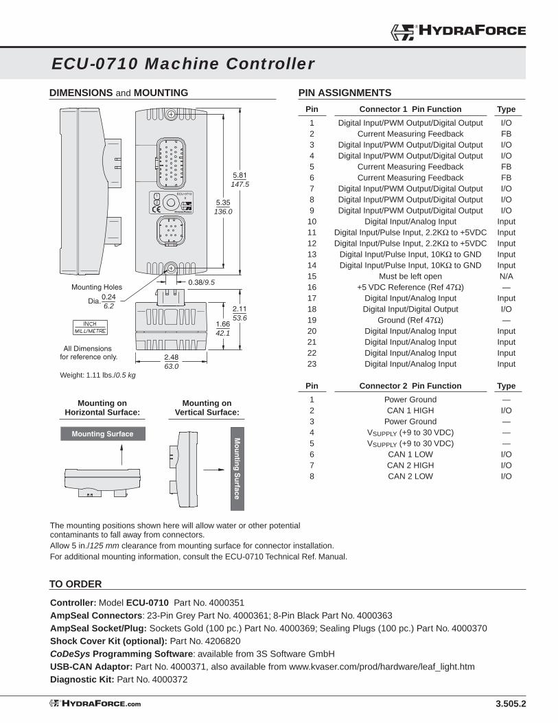
3.505.2
ECU-0710 Machine Controller
DIMENSIONS and MOUNTING PIN ASSIGNMENTS
®HYDRAFORCE
HYDRAFORCE.com®
TO ORDER
Controller: Model ECU-0710 Part No. 4000351AmpSeal Connectors: 23-Pin Grey Part No. 4000361; 8-Pin Black Part No. 4000363AmpSeal Socket/Plug: Sockets Gold (100 pc.) Part No. 4000369; Sealing Plugs (100 pc.) Part No. 4000370Shock Cover Kit (optional): Part No. 4206820CoDeSys Programming Software: available from 3S Software GmbHUSB-CAN Adaptor: Part No. 4000371, also available from www.kvaser.com/prod/hardware/leaf_light.htmDiagnostic Kit: Part No. 4000372
Weight: 1.11 lbs./0.5 kg
Mounting on Horizontal Surface:
Mounting on Vertical Surface:
The mounting positions shown here will allow water or other potential contaminants to fall away from connectors.Allow 5 in./125 mm clearance from mounting surface for connector installation.For additional mounting information, consult the ECU-0710 Technical Ref. Manual.
1 ECU-0710X
2 5.35136.0
1.6642.1
0.38/9.5
2.4863.0
0.246.2
Dia.
Mounting Holes
2.1153.6
5.81147.5
All Dimensions for reference only.
Pin Connector 1 Pin Function Type
1 Digital Input/PWM Output/Digital Output I/O 2 Current Measuring Feedback FB 3 Digital Input/PWM Output/Digital Output I/O 4 Digital Input/PWM Output/Digital Output I/O 5 Current Measuring Feedback FB 6 Current Measuring Feedback FB 7 Digital Input/PWM Output/Digital Output I/O 8 Digital Input/PWM Output/Digital Output I/O 9 Digital Input/PWM Output/Digital Output I/O 10 Digital Input/Analog Input Input 11 Digital Input/Pulse Input, 2.2KΩ to +5VDC Input 12 Digital Input/Pulse Input, 2.2KΩ to +5VDC Input 13 Digital Input/Pulse Input, 10KΩ to GND Input 14 Digital Input/Pulse Input, 10KΩ to GND Input 15 Must be left open N/A 16 +5 VDC Reference (Ref 47Ω) — 17 Digital Input/Analog Input Input 18 Digital Input/Digital Output I/O 19 Ground (Ref 47Ω) — 20 Digital Input/Analog Input Input 21 Digital Input/Analog Input Input 22 Digital Input/Analog Input Input 23 Digital Input/Analog Input Input
Pin Connector 2 Pin Function Type
1 Power Ground — 2 CAN 1 HIGH I/O 3 Power Ground — 4 VSUPPLY (+9 to 30 VDC) — 5 VSUPPLY (+9 to 30 VDC) — 6 CAN 1 LOW I/O 7 CAN 2 HIGH I/O 8 CAN 2 LOW I/O
Mounting Surface Mo
un
ting
Su
rface

3.506.1
ECU-2415 Machine Controller
ELECTRONIC CONTROLS
INPUTS / OUTPUTS — 49 Total
HYDRAFORCE.com®
Note: The ECU-2415 has inputs and outputs that can be confi gured in multiple ways. For more information, consult the ECU-2415 Technical Reference Manual.
Max. I/O Digital In Digital In Pulse Analog Current PWM Digital Out Digital Out Count (SWG) (SWB) Input Input Feedback (Source) (Source) (Sink)
1 X
10 X
6 X X
8 X X
8 X X X
16 X X X
49 25 14 8 6 10 24 24 0
FEATURES• Advanced electronic design for
reliability and accuracy.• Reliable operation in real-world
temperature conditions from -40˚ to +70˚C.
• Fully-sealed, compact cast-aluminum housing.
• Inputs and Outputs are protected against shorts.
• Outputs have diagnostic capability.• No external cooling or heat
dissipation required.• Software developed with
CoDeSys. 2.3 Programming Tool.
RATINGS
POWER REQUIREMENTS:Operating Voltage: 9 to 30 VDCIdle Power Consumption: approximately 1 WattOperating Current: 10 Amp Max. continuous current, with full external load.Over-Voltage: 34 VDC maximum
REFERENCE VOLTAGES:(1) 5 VDC Potentiometer Reference: 5 mA DC
COMMUNICATION:(2) ISO CAN 2.0B Interfaces: CANopen, J1939, or user-programmable.
PROCESSING and MEMORY:Microprocessor: 16-bit at 40 MHz; Flash ROM: 254 KbyteSRAM: 256 Kbyte; EEPROM: 6200 bytes
ENVIRONMENTAL RATINGS:Operating Temperature: –40°C to+70°C; Storage Temperature: –50°C to +85°CWater Resistance: meets IP67 standards (per IEC 660529)Humidity Tolerance: Rel. Humidity > 90% from +25°C to +55°C
(per IEC 60068-2-30 Test Db) Radiated Immunity: 20 to 2000 MHz at 30 V/m (per 2005/83/EC Annex IX)Vibration: 3.5Grms random from 10 to 500 Hz (per IEC 60068-2-64 Test Fh)Shock: 50g peak (per IEC 60068-2-27 and -29 Tests Ea and Eb)Corrosion: 50 g/l, NaCl for 24 hours at +35°C (per ISO 9227)
DESCRIPTIONThe ECU-2415 Machine Control is a general-purpose programmable controller designed to withstand the real-world environmental demands of the off-highway mobile market. The ECU-2415 can be used as a stand-alone controller, or for integrating into a CAN network with other devices.
Input confi guration can be set for up to 39 inputs consisting of Digital, Pulse, Current Measuring Feedback and Analog inputs. Output confi guration can be set for a total of 24 outputs consisting of up to 24 PWM or digital high-side drivers. All outputs are capable of driving up to 3.0 Amps.
Note: Refer to Input/Output table below for pin confi guration capability. Refer to ECU-2415 Technical Reference Manual for specifi c data and ratings of individual inputs and outputs.

3.506.2
ECU-2415 Machine Controller
®HYDRAFORCE
HYDRAFORCE.com®
Continued on following page . . .
PIN ASSIGNMENTS PIN ASSIGNMENTS
Pin Connector 1 Pin Function Type
1 Digital I/P/ PWM O/P/ Digital O/P (no open detect.) I/O
2 Digital I/P/ PWM O/P/ Digital O/P (no open detect.) I/O
3 Current Measuring Feedback FB
4 Current Measuring Feedback FB
5 Current Measuring Feedback FB
6 Current Measuring Feedback FB
7 Digital I/P/ PWM O/P/ Digital O/P (open detect.) I/O
8 Digital I/P/ PWM O/P/ Digital O/P (open detect.) I/O
9 Digital I/P/ PWM O/P/ Digital O/P (no open detect.) I/O
10 Current Measuring Feedback FB
11 Digital I/P/ PWM O/P/ Digital O/P (open detect.) I/O
12 Ground —
13 Digital I/P/ PWM O/P/ Digital O/P (open detect.) I/O
14 Current Measuring Feedback FB
15 Digital I/P/ PWM O/P/ Digital O/P (no open detect.) I/O
16 Digital I/P/ PWM O/P/ Digital O/P (no open detect.) I/O
17 Current Measuring Feedback FB
18 Digital I/P/ PWM O/P/ Digital O/P (no open detect.) I/O
19 Digital I/P/ PWM O/P/ Digital O/P (no open detect.) I/O
20 Current Measuring Feedback FB
21 Current Measuring Feedback FB
22 Current Measuring Feedback FB
23 Digital I/P/ PWM O/P/ Digital O/P (no open detect.) I/O
Pin Connector 2 Pin Function Type
1 Digital I/P/ PWM O/P/ Digital O/P (open detect.) I/O
2 Digital I/P/ PWM O/P/ Digital O/P (open detect.) I/O
3 Current Measuring Feedback FB
4 Current Measuring Feedback FB
5 Current Measuring Feedback FB
6 Current Measuring Feedback FB
7 Digital I/P/ PWM O/P/ Digital O/P (open detect.) I/O
8 Digital I/P/ PWM O/P/ Digital O/P (open detect.) I/O
9 Digital I/P/ PWM O/P/ Digital O/P (open detect.) I/O
10 Current Measuring Feedback FB
11 Digital I/P/ PWM O/P/ Digital O/P (open detect.) I/O
12 Ground —
13 Digital I/P/ PWM O/P/ Digital O/P (open detect.) I/O
14 Current Measuring Feedback FB
15 Digital I/P/ PWM O/P/ Digital O/P (open detect.) I/O
16 Digital I/P/ PWM O/P/ Digital O/P (open detect.) I/O
17 Current Measuring Feedback FB
18 Digital I/P/ PWM O/P/ Digital O/P (open detect.) I/O
19 Digital I/P/ PWM O/P/ Digital O/P (open detect.) I/O
20 Current Measuring Feedback FB
21 Current Measuring Feedback FB
22 Current Measuring Feedback FB
23 Digital I/P/ PWM O/P/ Digital O/P (open detect.) I/O
Pin Connector 3 Pin Function Type
1 +24 VDC Reference (Ref 300 mA) —
2 +5 VDC Reference (Ref 47Ω) —
3 Digital Input/ Analog Input, 2.2KΩ to +5VDC Input
4 Digital I/P/ Analog I/P, 82kΩ to GND/ V, 220Ω GND/A Input
5 Digital I/P/ Analog I/P, 82kΩ to GND/ V, 220Ω GND/A Input
6 Digital I/P/ Analog I/P, 82kΩ to GND/ V, 220Ω GND/A Input
7 Digital I/P/ Analog I/P, 82kΩ to GND/ V, 220Ω GND/A Input
8 Digital Input/ Analog Input, 19.5kΩ to GND and +5VDC Input
9 +24 VDC Reference (Ref 300 mA) —
10 Ground —
11 Ground —
12 Ground —
13 Ground —
14 Digital Input, 2.2KΩ to +5VDC Input
15 Must be left open N/A
16 Digital Input/ Pulse Input, 2.2KΩ to +5VDC Input
17 Digital Input/ Pulse Input, 2.2KΩ to +5VDC Input
18 Digital Input/ Pulse Input, 2.2KΩ to +5VDC Input
19 Digital Input/ Pulse Input, 2.2KΩ to +5VDC Input
20 Digital Input/ Pulse Input, 2.2KΩ to +5VDC Input
21 Digital Input/ Pulse Input, 2.2KΩ to +5VDC Input
22 Digital Input/ Pulse Input, 2.2KΩ to +5VDC Input
23 Digital Input/ Pulse Input, 2.2KΩ to +5VDC Input
Pin Connector 4 Pin Function Type
1 Power Ground —
2 CAN 1 HIGH I/O
3 Power Ground —
4 VSUPPLY (+9 to 30 VDC) —
5 VSUPPLY (+9 to 30 VDC) —
6 CAN 1 LOW I/O
7 CAN 2 HIGH I/O
8 CAN 2 LOW I/O

3.506.3
ECU-2415 Machine Controller
ELECTRONIC CONTROLS
HYDRAFORCE.com®
TO ORDER
Controller: Model ECU-2415 Part No. 4000352
AmpSeal Connectors: 23-Pin Grey Part No. 4000361; 23-Pin Blue Part No. 4000362 23-Pin Black Part No. 4000360; 8-Pin Black Part No. 4000363
AmpSeal Socket/Plug: Sockets Gold (100 pc.) Part No. 4000369; Sealing Plugs (100 pc.) Part No. 4000370
Shock Cover Kit (optional): Part No. 4206820
CoDeSys Programming Software: available from 3S Software GmbH
USB-CAN Adaptor: Part No. 4000371, also available from www.kvaser.com/prod/hardware/leaf_light.htm
Diagnostic Kit: Part No. 4000372
DIMENSIONS and MOUNTING
Weight: 1.55 lbs./0.7 kg
Mounting on Horizontal Surface:
Mounting on Vertical Surface:
The mounting positions shown here will allow water or other potential contaminants to fall away from connectors.Allow 5 in./125 mm clearance from mounting surface for connector installation.For additional mounting information, consult the ECU-2415 Technical Ref. Manual.
Mounting Surface Mo
un
ting
Su
rface
All Dimensions for reference only.
2 3
41
ECU-2xxx
5.35136.0
5.81147.5
0.38/9.50.246.2
Dia.
Mounting Holes
4.46113.3
1.3033.1
1.7544.5

3.507.1
ECU-2032 Machine Controller
ELECTRONIC CONTROLS
INPUTS / OUTPUTS — 52 Total
HYDRAFORCE.com®
Note: The ECU-2032 has inputs and outputs that can be confi gured in multiple ways. For more information, consult the ECU-2032 Technical Reference Manual.
Max. I/O Digital In Digital In Pulse Analog Current PWM Digital Out Digital Out Count (SWG) (SWB) Input Input Feedback (Source) (Source) (Sink)
1 X X
15 X X
16 X X
8 X X
8 X X X
4 X X
52 1 51 16 16 0 8 8 12
FEATURES• Advanced electronic design for
reliability and accuracy.• Reliable operation in real-world
temperature conditions from -40˚ to +70˚C.
• Fully-sealed, compact cast-aluminum housing.
• Inputs and Outputs are protected against shorts.
• Outputs have diagnostic capability.• No external cooling or heat
dissipation required.• Software developed with
CoDeSys. 2.3 Programming Tool.
RATINGS
POWER REQUIREMENTS:Operating Voltage: 9 to 30 VDCIdle Power Consumption: approximately 1 WattOperating Current: 10 Amp Max. continuous current, with full external load.Over-Voltage: 34 VDC maximum
REFERENCE VOLTAGES:(3) 5 VDC Potentiometer Reference: 10 mA DC(3) 12 VDC Potentiometer Reference: 200 mA DC
COMMUNICATION:(2) ISO CAN 2.0B Interfaces: CANopen, J1939, or user-programmable.
INTERNALLY REGULATED POWER SUPPLY:(1) 5 VDC: 250 mA maximum
PROCESSING and MEMORY:Microprocessor: 16-bit at 40 MHz; Flash ROM: 254 KbyteSRAM: 256 Kbyte; EEPROM: 6200 bytes
ENVIRONMENTAL RATINGS:Operating Temperature: –40°C to+70°C; Storage Temperature: –50°C to +85°CWater Resistance: meets IP67 standards (per IEC 660529)Humidity Tolerance: Rel. Humidity > 90% from +25°C to +55°C
(per IEC 60068-2-30 Test Db) Radiated Immunity: 20 to 2000 MHz at 30 V/m (per 2005/83/EC Annex IX)Vibration: 3.5Grms random from 10 to 500 Hz (per IEC 60068-2-64 Test Fh)Shock: 50g peak (per IEC 60068-2-27 and -29 Tests Ea and Eb)Corrosion: 50 g/l, NaCl for 24 hours at +35°C (per ISO 9227)
DESCRIPTIONThe ECU-2032 Machine Control is a general-purpose programmable controller designed to withstand the real-world environmental demands of the off-highway mobile market. The ECU-2032 can be used as a stand-alone controller, or for integrating into a CAN network with other devices.
Input confi guration can be set for up to 52 inputs consisting of Digital, Pulse, Current Measuring Feedback and Analog inputs. Output confi guration can be set for a total of 20 outputs consisting of up to 8 PWM or 20 digital high-side drivers. All outputs are capable of driving up to 3.0 Amps.
Note: Refer to Input/Output table below for pin confi guration capability. Refer to ECU-2032 Technical Reference Manual for specifi c data and ratings of individual inputs and outputs.

3.507.2
ECU-2032 Machine Controller
®HYDRAFORCE
HYDRAFORCE.com®
Continued on following page . . .
PIN ASSIGNMENTS PIN ASSIGNMENTS
Pin Connector 1 Pin Function Type
1 Analog Input, 10KΩ to +5VDC Input
2 Analog Input, 10KΩ to +5VDC Input
3 Analog Input, 10KΩ to +5VDC Input
4 Analog Input, 10KΩ to +5VDC Input
5 Digital I/P/ PWM O/P/ Digital O/P (no open detect.) I/O
6 Digital I/P/ PWM O/P/ Digital O/P (no open detect.) I/O
7 Digital I/P/ PWM O/P/ Digital O/P (no open detect.) I/O
8 Digital I/P/ PWM O/P/ Digital O/P (no open detect.) I/O
9 Digital I/P/ Pulse I/P, 10KΩ or 5kHz to Ground Input
10 Digital I/P/ Pulse I/P, 10KΩ or 5kHz to Ground Input
11 Digital I/P/ Pulse I/P, 10KΩ or 5kHz to Ground Input
12 Digital I/P/ Pulse I/P, 10KΩ or 5kHz to Ground Input
13 Digital I/P/ Pulse I/P, 10KΩ or 5kHz to Ground Input
14 Digital I/P/ Pulse I/P, 10KΩ or 5kHz to Ground Input
15 Ground —
16 +12VDC Reference (ref 200mA) —
17 Ground —
18 Digital I/P/ PWM O/P/ Digital O/P (open detect.) I/O
19 Digital I/P/ PWM O/P/ Digital O/P (open detect.) I/O
20 Digital I/P/ PWM O/P/ Digital O/P (open detect.) I/O
21 Digital I/P/ PWM O/P/ Digital O/P (open detect.) I/O
22 Digital I/P/ PWM O/P/ Digital O/P (open detect.) I/O
23 Digital I/P/ PWM O/P/ Digital O/P (open detect.) I/O
Pin Connector 2 Pin Function Type
1 Digital I/P/ PWM O/P/ Digital O/P (no open detect.) I/O
2 Digital I/P/ PWM O/P/ Digital O/P (no open detect.) I/O
3 Digital I/P/ PWM O/P/ Digital O/P (no open detect.) I/O
4 Digital I/P/ PWM O/P/ Digital O/P (no open detect.) I/O
5 Digital I/P/ Pulse I/P, 10KΩ or 5kHz to Ground Input
6 Digital I/P/ Pulse I/P, 10KΩ or 5kHz to Ground Input
7 Digital I/P/ Pulse I/P, 10KΩ or 5kHz to Ground Input
8 Digital I/P/ Pulse I/P, 10KΩ or 5kHz to Ground Input
9 Ground —
10 Digital I/P/ Pulse I/P, 10KΩ or 5kHz to Ground Input
11 Digital I/P/ Pulse I/P, 10KΩ or 5kHz to Ground Input
12 Digital I/P/ Pulse I/P, 10KΩ or 5kHz to Ground Input
13 Digital I/P/ Pulse I/P, 10KΩ or 5kHz to Ground Input
14 Digital I/P/ Pulse I/P, 10KΩ or 5kHz to Ground Input
15 Digital I/P/ Pulse I/P, 10KΩ or 5kHz to Ground Input
16 Digital I/P / Digital O/P (open detect.) I/O
17 Digital I/P / Digital O/P (open detect.) I/O
18 Digital I/P / Digital O/P (open detect.) I/O
19 Digital I/P / Digital O/P (open detect.) I/O
20 Digital I/P/ PWM O/P/ Digital O/P (open detect.) I/O
21 Digital I/P/ PWM O/P/ Digital O/P (open detect.) I/O
22 Ground —
23 +12VDC Reference (ref 200mA) —
Pin Connector 3 Pin Function Type
1 Analog I/P, 0-5VDC, 41kΩ to +2.5VDC Input
2 +5 VDC Regulated Power Supply (Ref 250mA) —
3 Digital I/P/ Analog I/P, 0-5VDC or 0-22.7mA to +2.5VDC Input
4 +5 VDC Reference (Ref +47Ω) —
5 Digital I/P/ Analog I/P, 0-5VDC or 0-22.7mA to +2.5VDC Input
6 +5 VDC Reference (Ref +47Ω) —
7 Digital I/P/ Analog I/P, 0-5VDC or 0-22.7mA to +2.5VDC Input
8 +5 VDC Reference (Ref +47Ω) —
9 Ground —
10 Digital I/P/ Analog I/P, 0-5VDC or 0-22.7mA to +2.5VDC Input
11 Analog I/P, 0-5VDC, 41kΩ to +2.5VDC Input
12 Analog I/P, 0-5VDC or 0-22.7mA, to +5VDC Input
13 Analog I/P, 0-5VDC or 0-22.7mA, to +5VDC Input
14 Analog I/P, 0-5VDC or 0-22.7mA, to +5VDC Input
15 Must be left open —
16 +12VDC Reference (ref 200mA) —
17 Ground (Ref -47Ω) —
18 Analog Input, 2.2KΩ to +5VDC Input
19 Ground (Ref -47Ω) —
20 Analog Input, 92KΩ to +46VDC Input
21 Ground (Ref -47Ω) —
22 Analog Input, 2.2KΩ to +5VDC Input
23 Ground (Ref -47Ω) —
Pin Connector 4 Pin Function Type
1 Power Ground —
2 CAN 1 HIGH I/O
3 Power Ground —
4 VSUPPLY (+9 to 30 VDC) —
5 VSUPPLY (+9 to 30 VDC) —
6 CAN 1 LOW I/O
7 CAN 2 HIGH I/O
8 CAN 2 LOW I/O

3.507.3
ECU-2032 Machine Controller
ELECTRONIC CONTROLS
HYDRAFORCE.com®
TO ORDER
Controller: Model ECU-2032 Part No. 4000355
AmpSeal Connectors: 23-Pin Grey Part No. 4000361; 23-Pin Blue Part No. 4000362 23-Pin Black Part No. 4000360; 8-Pin Black Part No. 4000363
AmpSeal Socket/Plug: Sockets Gold (100 pc.) Part No. 4000369; Sealing Plugs (100 pc.) Part No. 4000370
Shock Cover Kit (optional): Part No. 4206820
CoDeSys Programming Software: available from 3S Software GmbH
USB-CAN Adaptor: Part No. 4000371, also available from www.kvaser.com/prod/hardware/leaf_light.htm
Diagnostic Kit: Part No. 4000372
DIMENSIONS and MOUNTING
Weight: 1.55 lbs./0.7 kg
Mounting on Horizontal Surface:
Mounting on Vertical Surface:
The mounting positions shown here will allow water or other potential contaminants to fall away from connectors.Allow 5 in./125 mm clearance from mounting surface for connector installation.For additional mounting information, consult the ECU-2032 Technical Ref. Manual.
Mounting Surface Mo
un
ting
Su
rface
All Dimensions for reference only.
2 3
41
ECU-2xxx
5.35136.0
5.81147.5
0.38/9.50.246.2
Dia.
Mounting Holes
4.46113.3
1.3033.1
1.7544.5

3.508.1
ECU-2820 Machine Controller
ELECTRONIC CONTROLS
INPUTS / OUTPUTS — 49 Total
HYDRAFORCE.com®
Note: The ECU-2820 has inputs and outputs that can be confi gured in multiple ways. For more information, consult the ECU-2820 Technical Reference Manual.
Max. I/O Digital In Digital In Pulse Analog Current PWM Digital Out Digital Out Count (SWG) (SWB) Input Input Feedback (Source) (Source) (Sink)
4 X
4 X
24 X X X
8 X X
4 X X
8 X X
52 0 48 8 8 4 24 24 4
FEATURES• Advanced electronic design for
reliability and accuracy.• Reliable operation in real-world
temperature conditions from -40˚ to +70˚C.
• Fully-sealed, compact cast-aluminum housing.
• Inputs and Outputs are protected against shorts.
• Outputs have diagnostic capability.• No external cooling or heat
dissipation required.• Software developed with
CoDeSys. 2.3 Programming Tool.
RATINGS
POWER REQUIREMENTS:Operating Voltage: 9 to 30 VDCIdle Power Consumption: approximately 1 WattOperating Current: 10 Amp Max. continuous current, with full external load.Over-Voltage: 34 VDC maximum
INTERNALLY REGULATED POWER SUPPLY:(1) 5 VDC: 250 mA maximum across both pins(1) 12 VDC: 200 mA maximum across both pins
COMMUNICATION:(2) ISO CAN 2.0B Interfaces: CANopen, J1939, or user-programmable.
PROCESSING and MEMORY:Microprocessor: 16-bit at 40 MHz; Flash ROM: 254 KbyteSRAM: 256 Kbyte; EEPROM: 6200 bytes
ENVIRONMENTAL RATINGS:Operating Temperature: –40°C to+70°C; Storage Temperature: –50°C to +85°CWater Resistance: meets IP67 standards (per IEC 660529)Humidity Tolerance: Rel. Humidity > 90% from +25°C to +55°C
(per IEC 60068-2-30 Test Db) Radiated Immunity: 20 to 2000 MHz at 30 V/m (per 2005/83/EC Annex IX)Vibration: 3.5Grms random from 10 to 500 Hz (per IEC 60068-2-64 Test Fh)Shock: 50g peak (per IEC 60068-2-27 and -29 Tests Ea and Eb)Corrosion: 50 g/l, NaCl for 24 hours at +35°C (per ISO 9227)
DESCRIPTIONThe ECU-2820 Machine Control is a general-purpose programmable controller designed to withstand the real-world environmental demands of the off-highway mobile market. The ECU-2820 can be used as a stand-alone controller, or for integrating into a CAN network with other devices.
Input confi guration can be set for up to 52 inputs consisting of Digital, Pulse, Current Measuring Feedback and Analog inputs. Output confi guration can be set for a total of 28 outputs consisting of up to 24 PWM or digital high-side drivers and up to 4 digital low-side drivers. All outputs are capable of driving up to 3.0 Amps.
Note: Refer to Input/Output table below for pin confi guration capability. Refer to ECU-2820 Technical Reference Manual for specifi c data and ratings of individual inputs and outputs.

3.508.2
ECU-2820 Machine Controller
®HYDRAFORCE
HYDRAFORCE.com®
Continued on following page . . .
PIN ASSIGNMENTS PIN ASSIGNMENTS
Pin Connector 1 Pin Function Type
1 Digital I/P/ PWM O/P/ Digital O/P (no open detect.) I/O
2 Digital I/P/ PWM O/P/ Digital O/P (no open detect.) I/O
3 Digital I/P/ PWM O/P/ Digital O/P (no open detect.) I/O
4 Digital I/P/ PWM O/P/ Digital O/P (no open detect.) I/O
5 Current Measuring Feedback FB
6 Current Measuring Feedback FB
7 Digital I/P/ PWM O/P/ Digital O/P (no open detect.) I/O
8 Digital I/P/ PWM O/P/ Digital O/P (no open detect.) I/O
9 Ground —
10 Ground —
11 Ground —
12 Analog Input, 2.2KΩ to +5VDC or 220Ω to 22.7mA Input
13 Auxiliary VSUPPLY (3A max) for External Devices —
14 Digital I/P/ PWM O/P/ Digital O/P (no open detect.) I/O
15 Digital I/P/ PWM O/P/ Digital O/P (no open detect.) I/O
16 Digital I/P/ PWM O/P/ Digital O/P (no open detect.) I/O
17 Digital I/P/ PWM O/P/ Digital O/P (no open detect.) I/O
18 Digital Input/ Digital Output (open detect.) I/O
19 Digital Input, 10KΩ to Ground Input
20 Digital Input, 10KΩ to Ground Input
21 Digital Input/ Digital Output (open detect.) I/O
22 Digital I/P/ PWM O/P/ Digital O/P (no open detect.) I/O
23 Digital I/P/ PWM O/P/ Digital O/P (no open detect.) I/O
Pin Connector 2 Pin Function Type
1 Digital I/P/ PWM O/P/ Digital O/P (no open detect.) I/O
2 Digital I/P/ PWM O/P/ Digital O/P (no open detect.) I/O
3 Current Measuring Feedback FB
4 Current Measuring Feedback FB
5 Digital I/P/ PWM O/P/ Digital O/P (no open detect.) I/O
6 Digital I/P/ PWM O/P/ Digital O/P (no open detect.) I/O
7 Digital I/P/ PWM O/P/ Digital O/P (no open detect.) I/O
8 Digital I/P/ PWM O/P/ Digital O/P (no open detect.) I/O
9 Digital I/P/ PWM O/P/ Digital O/P (no open detect.) I/O
10 Digital I/P/ PWM O/P/ Digital O/P (no open detect.) I/O
11 Back-up VSUPPLY (+9 to 30 VDC) for CPU —
12 Analog Input, 2.2KΩ to +5VDC or 220Ω to 22.7mA Input
13 Ground —
14 Ground —
15 Ground —
16 Digital I/P/ PWM O/P/ Digital O/P (no open detect.) I/O
17 Digital I/P/ PWM O/P/ Digital O/P (no open detect.) I/O
18 Digital Input/ Digital Output (open detect.) I/O
19 Digital Input, 10KΩ to Ground Input
20 Digital Input, 10KΩ to Ground Input
21 Digital Input/ Digital Output (open detect.) I/O
22 Digital I/P/ PWM O/P/ Digital O/P (no open detect.) I/O
23 Digital I/P/ PWM O/P/ Digital O/P (no open detect.) I/O
Pin Connector 3 Pin Function Type
1 +12 VDC Regulated Power Supply (max 200mA) —
2 +5 VDC Regulated Power Supply (max 250mA) —
3 Ground —
4 Ground —
5 Digital I/P/ Analog I/P, 82KΩ to GND/V, 220Ω to GND/A Input
6 Digital I/P/ Analog I/P, 82KΩ to GND/V, 220Ω to GND/A Input
7 Digital I/P/ Analog I/P, 82KΩ to GND/V, 220Ω to GND/A Input
8 Digital I/P/ Analog I/P, 82KΩ to GND/V, 220Ω to GND/A Input
9 +12 VDC Regulated Power Supply (max 200mA) —
10 +12 VDC Regulated Power Supply (max 200mA) —
11 Ground —
12 Ground —
13 Digital I/P/ Analog I/P, 82KΩ to GND/V, 220Ω to GND/A Input
14 Digital I/P/ Analog I/P, 82KΩ to GND/V, 220Ω to GND/A Input
15 Must be left open —
16 Digital Input/ Pulse Input, 10KΩ or 5kHz to Ground Input
17 Digital Input/ Pulse Input, 10KΩ or 5kHz to Ground Input
18 Digital Input/ Pulse Input, 10KΩ or 5kHz to Ground Input
19 Digital Input/ Pulse Input, 10KΩ or 5kHz to Ground Input
20 Digital Input/ Pulse Input, 10KΩ or 5kHz to Ground Input
21 Digital Input/ Pulse Input, 10KΩ or 5kHz to Ground Input
22 Digital Input/ Pulse Input, 10KΩ or 5kHz to Ground Input
23 Digital Input/ Pulse Input, 10KΩ or 5kHz to Ground Input
Pin Connector 4 Pin Function Type
1 Power Ground —
2 CAN 1 HIGH I/O
3 Power Ground —
4 VSUPPLY (+9 to 30 VDC) —
5 VSUPPLY (+9 to 30 VDC) —
6 CAN 1 LOW I/O
7 CAN 2 HIGH I/O
8 CAN 2 LOW I/O

3.508.3
ECU-2820 Machine Controller
ELECTRONIC CONTROLS
HYDRAFORCE.com®
TO ORDER
Controller: Model ECU-2820 Part No. 4000356
AmpSeal Connectors: 23-Pin Grey Part No. 4000361; 23-Pin Blue Part No. 4000362 23-Pin Black Part No. 4000360; 8-Pin Black Part No. 4000363
AmpSeal Socket/Plug: Sockets Gold (100 pc.) Part No. 4000369; Sealing Plugs (100 pc.) Part No. 4000370
Shock Cover Kit (optional): Part No. 4206820
CoDeSys Programming Software: available from 3S Software GmbH
USB-CAN Adaptor: Part No. 4000371, also available from www.kvaser.com/prod/hardware/leaf_light.htm
Diagnostic Kit: Part No. 4000372
DIMENSIONS and MOUNTING
Weight: 1.55 lbs./0.7 kg
Mounting on Horizontal Surface:
Mounting on Vertical Surface:
The mounting positions shown here will allow water or other potential contaminants to fall away from connectors.Allow 5 in./125 mm clearance from mounting surface for connector installation.For additional mounting information, consult the ECU-2820 Technical Ref. Manual.
Mounting Surface Mo
un
ting
Su
rface
All Dimensions for reference only.
2 3
41
ECU-2xxx
5.35136.0
5.81147.5
0.38/9.50.246.2
Dia.
Mounting Holes
4.46113.3
1.3033.1
1.7544.5

3.520.1
Electronic Control Units — Technical Reference
User Liability and Safety — OEM ResponsibilityFull responsibility for the safe and effective functioning of the equipment into which HydraForce electronic controls are installed is assumed by the OEM of the equipment. HydraForce assumes no responsibility for application performance, or for the consequences of improper application or equipment malfunction.
An emergency stop function should be included on all safety-critical systems to switch off the main power supply for the output signals of the machine’s electronic control system. The main supply voltage should be designed to switch off immediately when unsafe conditions are encountered. A manual emergency stop switch should be clearly visible and easily accessed by the machine or vehicle operator.
Absolute Maximum RatingsOperating Temperature: –40°C to 85°CStorage Temperature: –50°C to 125°CSupply Voltage: 9 to 32 VDCOutput Load Current per Channel: Up to 2 AmpsTotal Output Current: Varies by specifi c model
CAN (Controller Area Networks) PortsAll HydraForce machine controllers have CAN ports that conform to CAN 2.0b specifi cations, including CAN shield.
Module Supply Voltage / Maximum Current RatingHydraForce machine controllers are designed to operate with a 9 to 32 VDC power supply, and are protected against reverse polarity. The voltage is internally monitored for Low/High Voltage and Load Dump. See individual product pages for maximum current ratings for specifi c models.
Input/Output Types and Specifi cationsHydraForce machine controllers include input and output pins for multiple I/O functions that are software-confi gurable by the OEM or the machine user. See individual product pages for details about each model’s features and functions.
Inputs — GeneralThe controllers’ input pins support one or more of the following input types:
• Digital in: Switch to Ground and Battery• Analog in: Voltage and Resistive• Frequency in: Speed and PWM
Communication — GeneralModel Dependent: CAN2.0
Key Switch InputThe key switch input allows the power to be turned On or Off manually. After the power is applied, the software will have control of all the inputs and outputs. The software can also disable the function of the key switch input.
• Provide a method of resetting the entire ECU.• Provide software option for key switch override.• Allows low battery drain (10 mA) when ECU is “asleep.”• Internal pull-down resistor is available for an external signal to
turn off the key switch input.• Input is protected from ESD and EMI.• Key switch status is monitored by software.
Inputs — Digital• Input voltage below minimum results in a non-damaging,
non-latching reading saturated to the low limit.• Input voltage above maximum results in a non-damaging,
non-latching reading saturated to the high limit.
Switch-to-Ground Features• Switch-to-ground inputs are normally pulled high to +13 VDC
through 2KΩ resistor when they are fl oating.• Inputs are protected from ESD, EMI and short to +Battery
faults.• Fast response times.
Specifi cations for Switch-to-Ground Inputs:Short ckt current: 10 mA DC maximumMaximum Resistance for On: 50Ω to GroundMinimum Resistance for Off: 4KΩ to GroundNon-Damaging Voltage Range: 0 to 32 VDC continuous
Switch to +Battery Features• Switch to battery inputs will detect a signal of +Batt –2V
through a series resistance of 50Ω.• Inputs have an internal pull-down resistor• All inputs are protected from ESD, EMI, transients and
short-to-ground faults.
Specifi cations for Switch to +Battery Inputs:Activation Resistance: 50Ω maximum to +BattDe-Activation Resistance: 4KΩ minimum to +BattNon-Damaging Voltage Range: –32 to +32 VDC continuous
PRODUCT OVERVIEW — INPUTS/OUTPUTS
ELECTRONIC CONTROLS
Technical Reference Information for Controller Models ECU-ML and ECU-MM
HYDRAFORCE.com®
Note: for Controller Model ECU-MS, see pages 3.520.5–8

3.520.2
INPUTS/OUTPUTS (cont’d.)
Electronic Control Units — Technical Reference
Inputs — Analog Voltage• Input can measure voltage of analog sensors and can also
serve as a current source with an internal 22KΩ pull-up resistor to +13 VDC.
• Input-open reads as 13 VDC; input short reads as 0 VDC.• Protection for Short to +Batt and ground as well as ESD
and EMI, provided internally.
Specifi cations for Analog Inputs:Input Voltage: 0 to 5 VDCInput Accuracy: 2% Full ScalePull-Up Resistance: 22KΩ to +13 VDCAnalog to Digital Resolution: 5mVSampling Rate: 2 msec.
Inputs — Analog Resistive (Temperature)• Resistive or analog sensor input.• Internal protection for short-to-battery or ground.• ESD and EMI protected.
Specifi cations for Resistive Sensor (Temperature) Inputs:Working Range: 0 to 5 VDCPull-Up Resistance: 499Ω to +5 VDCAnalog to Digital Resolution: 5mVAccuracy: ±50mV
Inputs — Frequency (Timing)Frequency inputs can be logic-level pulse pickup units (Hall Effect), Variable Reluctance (VR), PWM duty-cycle or frequency-encoded sensors, or switch-to-ground.
Features for Variable Reluctance:• Inputs are individually software-confi gurable as Passive
(balanced) or Active (unbalanced) sensors.• Adjacent input channels can be paired up as differential or
single-ended to provide direction decoding.• Diagnostic functions available through software confi guration
are maximum frequency and maximum period faults. Direction and fault counter diagnostics are also available.
Specifi cations for Variable Reluctance:Input Impedence: 20KΩ ±10% input to input.Input Measurable Limits: 0.5V to 120V p-pFrequency Range: 0.1 to 10 KHz programmableFrequency Accuracy: ±1% of actualNon-Damaging Voltage Range: –0.7 to 32 VDCNote: When using these inputs, best results will be obtained
when a sensor is connected to the ECU with twisted shielded pair to reduce noise. The shield is then grounded to the –Battery pin on the ECU.
PWM Inputs:These inputs allow an interface to active PWM and speed sensors. The inputs can be confi gured to measure both duty cycle and frequency.
Specifi cations for PWM Inputs:Input Low Threshold: <1.0 VDCInput High Threshold: >4.0 VDCInput Pull Up Resistance: 2 kΩ to +5 VDCFrequency Range: 0.6 Hz to 10 KHzFrequency Accuracy: ±1% for 0.6 Hz to 4 KHz;
±2% for 4 KHz to 10 KHzTiming Resolution: 1 µsec.Duty Cycle Range: 3% to 97%Duty Cycle Accuracy: ±1%Non-Damaging Voltage Range: –0.7 to 32 VDC
Alternator Input:This input monitors the alternator frequency and voltage for proper operation. This can also be used for measuring engine speed.
• Frequency Range: 3 Hz to 10 KHz• Accuracy and Resolution: 2% of input• Voltage Range: 0.5 to 100 Vpeak
Outputs — GeneralHydraForce machine controllers include factory-programmable output circuits confi gured via software. The controllers’ output pins support one or more of the following output types:
• Digital out: 2 Amp Sourcing, 300 milliamp Sinking• PWM: 1-Wire and 2-Wire 2 Amp Drivers
Outputs — Digital2 Amp Sourcing Driver• Protection Driver: Outputs will survive shorts to +Bat, –Bat
through any impedance with no degradation in performance. If commanded ON, driver remains ON during 80V jump start and load dump unless current limit is exceeded during these events, in which case the driver is disabled and a short-to-ground diagnostic is reported. If driver protection feature disables driver during these events, the driver is allowed to retry within 10 ms.
• Protection Load: If commanded ON, driver remains ON during 80V jump start and load dump unless current limit is exceeded during these events. If commanded OFF, driver will not source more then 100 µA during 80V jump start and load dump.
• Diagnostics: Output fault detection reports short to battery or ground, as well as open circuits whether drivers are in ON or OFF state.
Technical Reference Information for Controller Models ECU-ML and ECU-MM
®HYDRAFORCE
HYDRAFORCE.com®
Note: for Controller Model ECU-MS, see pages 3.520.5–8

Specifi cations for 2 Amp Sourcing Driver:Output Voltage: +Battery –2.0 VDC minimum at rated current.Output Current: 2 Amps maximum.Leakage Current: 350 µA maximum.Idle Current: Less than 10 mA.Turn-On Time: Less than 1 ms from command to 90% of
maximum output or voltage into resistive load at rated current.Maximum Switching Frequency for HydraForce Solenoids:Timing Resolution and Latency: Less than 1.25 ms.Return Connection: Separate return is NOT required for each
driver. A total of two specifi c returns are assigned to all ON/OFF drivers. Spreading drivers evenly between the two return lines is recommended.
System Reset Status: Drivers turn off during a system Reset.
Specifi cations for 300 mA Sinking Outputs:Load Supply Voltage: 32 VDC maximum.Load Current: 300 mA (current limited at 400 mA).Leakage Current: 0.5 mA with Driver Off.Transition Time: 20 µsec. maximum.Maximum Switching Frequency for Non-Inductive Loads:Typical Loads: Lamps, LEDs > 0.50 mA, relays with maximum
fl yback energy of 12 mJ
Outputs — PWM• Programmable control range of 50mA to 2A sourcing.• Full-time diagnostics detect open or short to battery or
ground; diagnostic limits for resistive, open circuit, leakage, or saturated driver faults.
• Software confi gurable for PWM, On/Off drivers, or Lamp drivers.
• One wire driver shares a common return with three other drivers.
• Two wire separate driver and return, both switch to avoid short to battery.
Specifi cations for PWM Outputs:Output Current: Programmable from 0 to 2.0 AmpsDC.Controllable Current Range: 50mA to Imax.Output Current Resolution: 2mA.Output Voltage: +Battery –2.0 VDC minimum at maximum load.Leakage Current: 100 µA maximum at driver off.Switching Frequency: 1 KHz.Dither Period: Programmable 4 mS to 500 mS in 2 mS
increments.Dither Amplitude: Programmable, 0 to 250 mA.Current Accuracy:
For 50 mA to 80 mA: ±9% > 0°C, ±11% < 0°CFor 80 mA to 150 mA: ±6% > 0°C, ±8% < 0°CFor 150 mA to 400 mA: ±4% > 0°C, ±5% < 0°CFor 400 mA to 2.0 A: ±2% > 0°C, ±3% < 0°C
Frequency Response: 30 Hz or better.
Sensor Power Supply RatingsModels that support sensor inputs include dedicated, regulated sensor power supplies and ground pins. See individual product pages for sensor power supply ratings.
Diagnostics:• Software controlled diagnostic functions executed every
15 mS.• Short-to-Ground: Supply voltage is <95% of sensor voltage
(5, 8 or 10 VDC) for two seconds minimum with ECU having been powered for three seconds minimum at fault detection.
• Short-to-Battery: Supply voltage is >105% of sensor voltage (5, 8 or 10 VDC) for two seconds minimum with ECU having been powered for three seconds minimum at fault detection.
Specifi cations:Output Voltage: 5 VDC ±0.25 VOutput Current: 200 mA minimumOutput Short-Circuit Current: 250 mA maximum
Specifi cations:Output Voltage: 8 VDC ±0.4 VOutput Current: 400 mA minimumOutput Short-Circuit Current: 450 mA maximum
Specifi cations:Output Voltage: 10 VDC +1.0/–3.0 VOutput Current: 3 A minimumOutput Short-Circuit Current: 3.5 A maximum
General RatingsReverse Polarity Protection: Controller will withstand reverse
polarity at supply voltage up to -16V for 12V nominal systems and up to -32V for 24V nominal systems.
Short-Circuit Protection: Inputs and outputs will withstand continuous short-circuit to all other leads including positive and negative terminals. When the short-circuit condition is ended, the controller will return to normal function.
Other Voltage Protection: Up to 30V for a 12V system and 80V for a 24V system for 2 minutes.
Automotive Electrical Transients — Conformance to the Following Standards:• ISO 7637; Road Vehicles: Electrical disturbance by conduction and Coupling.• SAE J1113-11: Immunity to conducted transients on power leads.• IEC 61000-4-4 2001-07: Immunity to electrical fast transient/burst• IEC 61000-4-11: Voltage dips and interruptions
3.520.3
Electronic Control Units — Technical Reference
ELECTRONIC CONTROLS
INPUTS/OUTPUTS (cont’d) / RATINGS
Technical Reference Information for Controller Models ECU-ML and ECU-MM
HYDRAFORCE.com®
Note: for Controller Model ECU-MS, see pages 3.520.5–8

Recommended Machine Wiring Guidelines• Wherever possible, avoid running wires in hot areas. Where
it is necessary to run wires in especially hot areas, use wire rated to 105°C. In general, wire rated to 85°C should always be used.
• Plastic or fl exible metal conduit is recommended to help prevent mechanical damage to wires.
• To help shield wires from EMI/RFI radiation, where possible run the wires next to or inside of metal machine surfaces.
• 18 AWG wire is recommended.• Keep wires supported along their length. Avoid wire harness
anchors that hold the wires rigid. Allowing the wires to “fl oat” is preferable.
• Use strain relief devices, and grommets for corner protection. Always protect wires from sharp metal parts and corners, and from moving or vibrating parts of the machine.
• Control wires and high-current-carrying wires should be separated from each other.
• Run sensor lines separately from digital and switching signals where possible. Twist sensor lines approximately one turn for every 10 mm (0.4 in.).
• For analog sensors, the ground wire should be connected to the sensor ground pin on the controller. Power to analog sensors should come from the controller’s sensor power source.
USB/CAN CommunicatorA USB/CAN connector allows the controller to exchange data with a PC. When connected to a PC, the controller functions as a USB slave; all electrical power is supplied by the PC; no other power source is required.
The USB/CAN connector has internal CAN bus terminating re-sistors which the user can control using the controller’s Service and Diagnostic tool. Refer to the controller’s software manual for setup information. Refer to the USB/CAN Connector product information sheet for specifi cations and connector pin details.
3.520.4
Electronic Control Units — Technical Reference
RATINGS (cont’d) / WIRING GUIDELINES / COMMUNICATIONS
EMC/EMI Modules conform to 89/336/EEC Directive ISO 14982 for
Agricultural and Forestry machineryEMI Emission: Modules conform to the following standards:Near Field Radiated Emissions: 150 KHz to 50 MHz;
SAE J1113-41: Limits and methods of measurement of radio disturbance characteristics of components and modules for the protection of receivers used on board vehicles.
Near Field Radiated Emissions: 30 MHz to 1000 MHz: ISO 13766; Earth-Moving machinery; Electromagnetic com-patibility.
Far Field Radiated Emissions: 30 MHz to 1000 MHz: CISPR 11:2003-03; Industrial, scientifi c and medical (ISM) radio frequency equipment; Electromagnetic disturbance characteristics; limits and methods of measurement.
Conducted Emissions: 150 KHz to 108 MHz: CISPR 25:2002-08; Radio disturbance characterisitcs for the protection of receivers used on board vehicles, boats, and on devices; limits and methods of measurement.
EMC Immunity: Conforms to the following standards:SAE J1113-21: Electromagnetic compatibility measurement
procedure for vehicle components; Part 21: Immunity to electromagnetic fi elds, 10 KHz to 18 GHz, absorber-lined chamber
IEC 61000-4-3 2002-03 Radiated Immunity 10V/MIEC 61000-4-5 2001-04 Surge Immunity (Lightning 2KV)IEC 61000-4-6 1996 Conducted RF Injection 150 KHz to
230 MHzIEC61000-4-8 2001 Power Frequency Magnetic Field
30 Amps/MeterSAE J1113-23 Electromagnetic compatibility measurement
procedure for Vehicle Components; Part 23: Immunity to Elec-tromagnetic Fields, 10 KHz to 200 MHz, Strip Line Method.
Electrostatic Discharge: Conforms to the following standards:IEC 61000-4-2 Electromagnetic Compatibility (ECM); Part 4-2:
Testing and Measurement Techniques; Electrostatic Dis-charge Immunity Test
SAE J1113-13 Electromagnetic Compatibility Measurement Procedure for Vehicle Components; Part 13: Immunity to Electrostatic Discharge
Machine Diagnostic ConnectorHydraForce recommends that a diagnostic connector be installed on machines controlled by HydraForce electronic controllers. The connector should be located to be convenient and readily accessible by the machine operator.
Data communication between the controller and a personal computer is accomplished via the machine’s CAN network. Teeing into the machine’s CAN bus, the diagnostic connector should have the following connections: CAN+, CAN–, CAN-shield, Battery+, Battery.
Technical Reference Information for Controller Models ECU-ML and ECU-MM
®HYDRAFORCE
HYDRAFORCE.com®
Note: for Controller Model ECU-MS, see pages 3.520.5–8

3.520.5
Electronic Control Units — Technical Reference
User Liability and Safety — OEM ResponsibilityFull responsibility for the safe and effective functioning of the equipment into which HydraForce electronic controls are installed is assumed by the OEM of the equipment. HydraForce assumes no responsibility for application performance, or for the consequences of improper application or equipment malfunction.
An emergency stop function should be included on all safety-critical systems to switch off the main power supply for the output signals of the machine’s electronic control system. The main supply voltage should be designed to switch off immediately when unsafe conditions are encountered. A manual emergency stop switch should be clearly visible and easily accessed by the machine or vehicle operator.
Absolute Maximum RatingsOperating Temperature: –40°C to 85°CStorage Temperature: –50°C to 125°CSupply Voltage: 9 to 32 VDCOutput Load Current per Channel: Up to 2 AmpsTotal Output Current: 15 Amps
CAN (Controller Area Networks) PortsAll HydraForce machine controllers have CAN ports that conform to CAN 2.0b specifi cations, including CAN shield.
Module Supply Voltage / Maximum Current RatingHydraForce machine controllers are designed to operate with a 9 to 32 VDC power supply, and are protected against reverse polarity. The voltage is internally monitored for Low/High Voltage and Load Dump. See individual product pages for maximum current ratings for specifi c models.
Input/Output Types and Specifi cationsHydraForce machine controllers include input and output pins for multiple I/O functions that are software-confi gurable by the OEM or the machine user. See individual product pages for details about each model’s features and functions.
Inputs — GeneralThe controllers’ input pins support one or more of the following input types:
• Digital in: Switch to Ground and Battery• Analog in: Voltage and Resistive• Frequency in: Frequency and PWM
Communication — GeneralModel Dependent: CAN2.0
Key Switch InputThe key switch input allows the power to be turned On or Off manually. After the power is applied, the software will have control of all the inputs and outputs. The software can also disable the function of the key switch input.
• Provide a method of resetting the entire ECU.• Provide software option for key switch override.• Allows low battery drain (10 mA) when ECU is “asleep.”• Internal pull-down resistor is available for an external signal to
turn off the key switch input.• Input is protected from ESD and EMI.• Key switch status is monitored by software.
Inputs — Digital• Input voltage below minimum results in a non-damaging,
non-latching reading saturated to the low limit.• Input voltage above maximum results in a non-damaging,
non-latching reading saturated to the high limit.
Switch-to-Ground Features• Switch-to-ground inputs are normally pulled high to +10 VDC
through 2KΩ resistor when they are fl oating.• Inputs are protected from ESD, EMI and short to +Battery
faults.• Fast response times.
Specifi cations for Switch-to-Ground Inputs:Short ckt current: 10 mA DC maximumMaximum Resistance for On: 50Ω to GroundMinimum Resistance for Off: 4KΩ to GroundNon-Damaging Voltage Range: 0 to 32 VDC continuous
Switch to +Battery Features• Switch to battery inputs will detect a signal of +Batt –2V
through a series resistance of 50Ω.• Inputs have an internal pull-down resistor• All inputs are protected from ESD, EMI, transients and
short-to-ground faults.
Specifi cations for Switch to +Battery Inputs:Activation Resistance: 50Ω maximum to +BattDe-Activation Resistance: 4KΩ minimum to +BattNon-Damaging Voltage Range: –32 to +32 VDC continuous
PRODUCT OVERVIEW — INPUTS/OUTPUTS
ELECTRONIC CONTROLS
Technical Reference Information for Controller Model ECU-MS
HYDRAFORCE.com®
Note: for Controller Models ECU-ML and ECU-MM, see pages 3.520.1–4

3.520.6
INPUTS/OUTPUTS (cont’d.)
Electronic Control Units — Technical Reference
Inputs — Analog Voltage• Input can measure voltage of analog sensors and can also
serve as a current source with an internal 16KΩ pull-up resistor to +10 VDC.
• Input-open reads as 10 VDC; input short reads as 0.2 VDC.• Protection for Short to +Batt and ground as well as ESD
and EMI, provided internally.
Specifi cations for Analog Inputs:Input Voltage: 0.5 to 4.5 VDCInput Accuracy: 2% Full ScalePull-Up Resistance: 16KΩ to +10 VDCAnalog to Digital Resolution: 5mV, 10 bitsSampling Rate: 2 msec.
Inputs — Analog Resistive (Temperature)• Resistive or analog sensor input.• Internal protection for short-to-battery or ground.• ESD and EMI protected.
Specifi cations for Resistive Sensor (Temperature) Inputs:Working Range: 0 to 5 VDCPull-Up Resistance: 499Ω to +5 VDCAnalog to Digital Resolution: 5mVAccuracy: 2.5%
Inputs — Frequency (Timing)Frequency inputs can be logic-level pulse pickup units (Hall Effect), Variable Reluctance (VR), PWM duty-cycle or frequency-encoded sensors, or switch-to-ground.
Features for Variable Reluctance:• Inputs are individually software-confi gurable as Passive
(balanced) or Active (unbalanced) sensors.• Adjacent input channels can be paired up as differential or
single-ended to provide direction decoding.• Diagnostic functions available through software confi guration
are maximum frequency and maximum period faults. Direction and fault counter diagnostics are also available.
Specifi cations for Variable Reluctance:Input Impedence: 20KΩ ±10% input to input.Input Measurable Limits: 0.55V to 120V p-pFrequency Range: 0.1 to 10 KHz programmableFrequency Accuracy: ±1% of actualNon-Damaging Voltage Range: –0.7 to 32 VDCNote: When using these inputs, best results will be obtained
when a sensor is connected to the ECU with twisted shielded pair to reduce noise. The shield is then grounded to the –Battery pin on the ECU.
PWM Inputs:These inputs allow an interface to active PWM and speed sensors. The inputs can be confi gured to measure both duty cycle and frequency.
Specifi cations for PWM Inputs:Input Low Threshold: <1.0 VDCInput High Threshold: >4.0 VDCInput Pull Up Resistance: 2 kΩ to +5 VDC
Specifi cations for Frequency Inputs:Frequency Range: 120 Hz to 1500 HzFrequency Accuracy: ±1%Timing Resolution: 1 µsec.Duty Cycle Range: 3% to 97%Duty Cycle Accuracy: ±0.5%Non-Damaging Voltage Range: –0.7 to 32 VDC
Outputs — GeneralHydraForce machine controllers include factory-programmable output circuits confi gured via software. The controllers’ output pins support one or more of the following output types:
• Digital out: 2 Amp Hi/Lo Driver, Sinking• PWM: 2-Wire, 2 Amp Drivers
Outputs — Digital2 Amp Low Side Driver• Protection Driver: Outputs will survive shorts to +Bat, –Bat
through any impedance with no degradation in performance. If commanded ON, driver remains ON during 80V jump start and load dump unless current limit is exceeded during these events, in which case the driver is disabled and a short-to-battery diagnostic is reported. If driver protection feature disables driver during these events, the driver is allowed to retry within 10 ms.
• Diagnostics: Output fault detection reports short to battery or ground, as well as open circuits whether drivers are in ON or OFF state.
Specifi cations for 2 Amp Sinking Outputs:Load Supply Voltage: 32 VDC maximum.Load Current: 2 AmpsLeakage Current: 0.5 mA with Driver Off.Transition Time: 100 µsec. maximum.
Technical Reference Information for Controller Model ECU-MS
®HYDRAFORCE
HYDRAFORCE.com®
Note: for Controller Models ECU-ML and ECU-MM, see pages 3.520.1–4

Outputs — PWM Hi/Lo Side• Programmable control range of 50mA to 2A sourcing.• Full-time diagnostics detect open or short to battery or
ground; diagnostic limits for resistive, open circuit, leakage, or saturated driver faults.
• Software confi gurable for PWM, On/Off drivers, or Lamp drivers.
• One wire driver shares a common return with three other drivers.
• Two wire separate driver and return, both switch to avoid short to battery.
Specifi cations for PWM Outputs:Output Current: Programmable from 0 to 2.0 Amps DC.Controllable Current Range: 50mA to full scale.Output Current Resolution: 1.5mA.Output Voltage: +Battery –2.8 VDC minimum at maximum load.Leakage Current: 100 µA maximum at driver off.Switching Frequency: 1 KHz.Dither Period: Programmable 4 mS to 500 mS in 2 mS
increments.Dither Amplitude: Programmable, 0 to 250 mA.Current Accuracy: ±10%@25°C, ±15% Imax.Frequency Response: 30 Hz or better.
Sensor Power Supply RatingsModels that support sensor inputs include dedicated, regulated sensor power supplies and ground pins. See individual product pages for sensor power supply ratings.
Diagnostics:• Software controlled diagnostic functions executed every
15 mS.• Short-to-Ground: Supply voltage is <95% of sensor voltage
(5, 8 or 10 VDC) for two seconds minimum with ECU having been powered for three seconds minimum at fault detection.
• Short-to-Battery: Supply voltage is >105% of sensor voltage (5, 8 or 10 VDC) for two seconds minimum with ECU having been powered for three seconds minimum at fault detection.
Specifi cations:Output Voltage: 5 VDC ±0.25 V, or 8 VDC ±0.4 VOutput Current: 330 mA minimumOutput Short-Circuit Current: 360 mA maximum
General RatingsReverse Polarity Protection: Controller will withstand reverse
polarity at supply voltage up to -16V for 12V nominal systems and up to -32V for 24V nominal systems.
Short-Circuit Protection: Inputs and outputs will withstand continuous short-circuit to all other leads including positive and negative terminals. When the short-circuit condition is ended, the controller will return to normal function.
Other Voltage Protection: Up to 30V for a 12V system and 80V for a 24V system for 2 minutes.
Automotive Electrical Transients — Conformance to the Following Standards:• ISO 7637; Road Vehicles: Electrical disturbance by conduction and coupling.• SAE J1113-11: Immunity to conducted transients on power leads.• IEC 61000-4-4 2001-07: Immunity to electrical fast transient/burst• IEC 61000-4-11: Voltage dips and interruptions
EMC/EMI Modules conform to 89/336/EEC Directive ISO 14982 for
Agricultural and Forestry machineryEMI Emission: Modules conform to the following standards:Near Field Radiated Emissions: 150 KHz to 50 MHz;
SAE J1113-41: Limits and methods of measurement of radio disturbance characteristics of components and modules for the protection of receivers used on board vehicles.
Near Field Radiated Emissions: 30 MHz to 1000 MHz: ISO 13766; Earth-Moving machinery; Electromagnetic com-patibility.
Far Field Radiated Emissions: 30 MHz to 1000 MHz: CISPR 11:2003-03; Industrial, scientifi c and medical (ISM) radio frequency equipment; Electromagnetic disturbance characteristics; limits and methods of measurement.
Conducted Emissions: 150 KHz to 108 MHz: CISPR 25:2002-08; Radio disturbance characterisitcs for the protection of receivers used on board vehicles, boats, and on devices; limits and methods of measurement.
EMC Immunity: Conforms to the following standards:SAE J1113-21: Electromagnetic compatibility measurement
procedure for vehicle components; Part 21: Immunity to electromagnetic fi elds, 10 KHz to 18 GHz, absorber-lined chamber
IEC 61000-4-3 2002-03 Radiated Immunity 10V/MIEC 61000-4-5 2001-04 Surge Immunity (Lightning 2KV)IEC 61000-4-6 1996 Conducted RF Injection 150 KHz to
230 MHzIEC61000-4-8 2001 Power Frequency Magnetic Field
30 Amps/MeterSAE J1113-23 Electromagnetic compatibility measurement
procedure for Vehicle Components; Part 23: Immunity to Elec-tromagnetic Fields, 10 KHz to 200 MHz, Strip Line Method.
3.520.7
Electronic Control Units — Technical Reference
ELECTRONIC CONTROLS
INPUTS/OUTPUTS (cont’d) / RATINGS
Technical Reference Information for Controller Model ECU-MS
HYDRAFORCE.com®
Note: for Controller Models ECU-ML and ECU-MM, see pages 3.520.1–4

USB/CAN CommunicatorA USB/CAN connector allows the controller to exchange data with a PC. When connected to a PC, the controller functions as a USB slave; all electrical power is supplied by the PC; no other power source is required.
The USB/CAN connector has internal CAN bus terminating re-sistors which the user can control using the controller’s Service and Diagnostic tool. Refer to the controller’s software manual for setup information. Refer to the USB/CAN Connector product information sheet for specifi cations and connector pin details.
3.520.8
Electronic Control Units — Technical Reference
RATINGS (cont’d) / WIRING GUIDELINES / COMMUNICATIONS
Electrostatic Discharge: Conforms to the following standards:IEC 61000-4-2 Electromagnetic Compatibility (ECM); Part 4-2:
Testing and Measurement Techniques; Electrostatic Discharge Immunity Test
SAE J1113-13 Electromagnetic Compatibility Measurement Procedure for Vehicle Components; Part 13: Immunity to Electrostatic Discharge
Machine Diagnostic ConnectorHydraForce recommends that a diagnostic connector be installed on machines controlled by HydraForce electronic controllers. The connector should be located to be convenient and readily accessible by the machine operator.
Data communication between the controller and a personal computer is accomplished via the machine’s CAN network. Teeing into the machine’s CAN bus, the diagnostic connector should have the following connections: CAN+, CAN–, CAN-shield, Battery+, Battery.
Recommended Machine Wiring Guidelines• Wherever possible, avoid running wires in hot areas. Where
it is necessary to run wires in especially hot areas, use wire rated to 105°C. In general, wire rated to 85°C should always be used.
• Plastic or fl exible metal conduit is recommended to help prevent mechanical damage to wires.
• To help shield wires from EMI/RFI radiation, where possible run the wires next to or inside of metal machine surfaces.
• 18 AWG wire is recommended.• Keep wires supported along their length. Avoid wire harness
anchors that hold the wires rigid. Allowing the wires to “fl oat” is preferable.
• Use strain relief devices, and grommets for corner protection. Always protect wires from sharp metal parts and corners, and from moving or vibrating parts of the machine.
• Control wires and high-current-carrying wires should be separated from each other.
• Run sensor lines separately from digital and switching signals where possible. Twist sensor lines approximately one turn for every 10 mm (0.4 in.).
• For analog sensors, the ground wire should be connected to the sensor ground pin on the controller. Power to analog sensors should come from the controller’s sensor power source.
Technical Reference Information for Controller Model ECU-MS
®HYDRAFORCE
HYDRAFORCE.com®
Note: for Controller Models ECU-ML and ECU-MM, see pages 3.520.1–4

3.558.1
CAN-Bus Keypads
ELECTRONIC CONTROLS
DESCRIPTIONThese soft-touch keypads are designed to be used with CAN-Bus J1939 network applications. They feature a black silicone overlay with custom legends and key groupings, and are available in an 8-key unit. The confi gurable keys are backlit and there are three amber indicator LEDs, which can be individually addressed via J1939 standards.
FEATURES• 8 buttons, 2 across x 4 high.• Dash-mountable.• SAE-J1939 compliant.• CAN-Bus controllable LED indicators.• Long life — tested to 3 million activations.• Custom legends and key combinations available
(minimum order required, consult factory).• Operating temperature: -40C to +85C.
RATINGSElectrical and Environmental:Sealing: IP67CE RatedPower: 8 to 32 VDC @ 2 amps maximumOperating and Storage Temperature: –40 to +85°C (-40 to 185°F)Humidity Tolerance at 115% of nominal voltage: 99% RH at 35°C for 240 hoursEMC: 100 V/m using twisted pair J1939-11 and J1939-15Fluid Compatibility: Diesel fuel, oil, unleaded gasoline, ethanol,
coolant additive, battery fl uid with 37% sulfuric acid or KCHVibration Rating: 5.3g random, three-axis; 3.5 sinusoidal
Mechanical:Life Cycle: 3 million activationsBacklighting: Green LED’s, one per keyIndicators: Amber LEDs; Qty: 24 for 8-key model;
See dimension drawing for locations.Connector: 4-pin Deutsch DTCommunications: J1939 CAN 2.0 Part B compliantMaterial: Silicone-based elastomer; Color: black
HYDRAFORCE.com®
Eight-Key

3.558.2
CAN-Bus Keypads
TO ORDER
CAN-Bus Keypad Model: 8-Key, 2 x4 Vertical Part No. 4206520Mating Connector Kit for 8-Key Model Part No. 4001953CAN Keypad User Manual for 8-Key Model Consult Factory
DIMENSIONS & MOUNTING
Eight-Key
®HYDRAFORCE
HYDRAFORCE.com®
MountingShaded Areas Cut Out
0.5915.1
4.56115.8
1.0526.6
0.9824.9
0.9123.1
0.6315.9
0.5714.4
0.8621.7
1.0827.5
0.7819.8
1.5038.1
3.0076.2 3.00
76.2
1.5038.1
1.5038.1
0.7920.0
INCHMILLIMETRE
2.1755.0
0.9824.8
Dimensions Shown are for Reference Only
Dia.
VentDo notobstruct.
1.6040.6
Dia.
0.287.0
Dia.
CAN_L
4-PIN Deutsch DT Connector
CAN_H
3
4
2
1
Ground
Power
8 KEYS — 2 x 4 Keypad — Vertical Configuration Shown
M6 x 1.0mm Stud
1 2
3 4
5 6
7 8

DESCRIPTIONHigh-accuracy heavy-duty pressure sensors with 1% total error band accuracy accomplished by marrying a high performance ASIC to a very stable, fi eld-proven polysilicon, thin-fi lm pressure sensor. These sensors are intended for use in demanding industrial and off-highway equipment.
FEATURES• Advanced ASIC technology for reliability and accuracy.• 1% total error band accuracy within -20 to 85°C temperature range.• Long term active stability and repeatability.• Broad temperature capability.• All-welded pressure construction.• Protected against EMI/RFI.• IP67 ingress rated.• Diagnostic rails.
3.652.1
Heavy-Duty Pressure Sensors
ELECTRONIC CONTROLS
DIMENSIONSTO ORDER
0 to 345 bar (5000 psi)Pressure Sensor Model No: ERP-345-RM-IM-06Part No. 4000672
0 to 35 bar (500 psi)Pressure Sensor Model No: ERP-35-RM-IM-06Part No. 4000664
Mating Connector: Metri-Pack® 150HF Part No. 4000669
Models ERP345, ERP35
RATINGSPERFORMANCE:Pressure Range:
ERP345: 0 to 345 bar (0 to 5000 psi)ERP35: 0 to 35 bar (0 to 500 psi)For alternate pressure ranges, consult factory.
Durability: Tested to 50 million cyclesOverpressure ERP345 (345 bar model):
Proof 150%; Burst 500%Overpressure ERP35 (35 bar model):
Proof 200%; Burst 1000%Proof Pressure: up to 10% intermittent duty cycle.Accuracy:
±1% of Span from -20 to 85°C±1.5% of Span from -40 to -20°C±1.5% of Span from 85 to 125°CStatic Accuracy Class: ±0.25% of span (BFSL Method) including linearity, hysteresis, non-repeatability at reference temperature 21°C/72°F.
Response Time: < 1 msSupply Voltage ERP345: 0 to 5VDCSupply Voltage ERP35: 4.5 to 5.5VDC
Supply Current: 3.5mARatiometric Output: 0.5–4.5VDCReverse Polarity
and Miswired Protected
INSTALLATION & PHYSICALSPECIFICATIONSElectrical Connection: Metri-Pack 150Pressure Port Material:
304 Stainless SteelSensor Material: 17-4PH SSHousing: 20% Glass Reinforced NylonInstall Torque: 27 Nm (20 ft-lbs)
ENVIRONMENTAL RATINGS:Operating and Storage Temperature:
–40°C to 125°CVibration: 20 grms (10 hrs. each axis)Shock: 100gs, 6msEMI / RFI Protection
EN61326 (Heavy Industrial): 30 V/M 500 KHz to 1 GHz
Weather Rating: IP67
HYDRAFORCE.com®
3-Pin Metri-Pack®
0.308
0.7118
Gnd.
+5V
Signal
0.236
1.0627
0.9424
SAE 69/16-18 UNF 2A
Optional MatingConnector
Dimensions arefor reference only.
INCHMILLIMETRE
2.0552
0.3910
0.4812
NOTE: See following page (3.652.2) for important Installation and Technical Reference Information.

TECHNICAL REFERENCE INFORMATION FOR ERP MODEL PRESSURE SENSORS
3.652.2
Pressure Sensor Installation and Reference Info.
HYDRAFORCE.com®
®HYDRAFORCE
WARNING- READ BEFORE INSTALLATIONUser Liability and Safety — OEM Responsibility
Full responsibility for the safe and effective functioning of the equipment into which HydraForce electronic controls are installed is assumed by the OEM of the equipment. HydraForce assumes no responsibility for application performance, or for the consequences of improper application or equipment malfunction.
A failure resulting in injury or damage may be caused by excessive overpressure, excessive vibration or pressure pulsation, excessive instrument temperature, corrosion of the pressure containing parts, or other misuse. Consult HydraForce Inc., Lincolnshire, IL, USA before installing if there are any questions or concerns.
1. Overpressure:Pressure spikes in excess of the rated overpressure capability of the sensor may cause irreversible electrical and/or mechanical damage to the pressure measuring and containing elements. Fluid hammer and surges can destroy any pressure sensor and must always be avoided. A pressure snubber should be installed to eliminate the damaging hammer effects. Fluid hammer occurs when a liquid fl ow is suddenly stopped, as with quick closing solenoid valves. Surges occur when fl ow is suddenly begun, as when a pump is turned on at full power or a valve is quickly opened. Liquid surges are particularly damaging to pressure sensors if the pipe is originally empty. To avoid damaging surges, fl uid lines should remain full (if possible), pumps should be brought up to power slowly, and valves opened slowly. To avoid damage from both fl uid hammer and surges, a surge chamber should be installed.
Symptoms of fl uid hammer and surge's damaging effects: • Pressure sensor exhibits an output at zero pressure
(large zero offset).• Pressure sensor output remains constant regardless of
pressure• In severe cases, there will be no output.
2. Freezing: Prohibit freezing of media in pressure port. Unit should be drained (mount in vertical position with electrical termination upward) to prevent possible overpressure damage from frozen media.
3. Static Electrical Charges: Any electrical device may be susceptible to damage when exposed to static electrical charges.
To avoid damage to the sensor observe the following:
• Ground the body of the sensor BEFORE making any electrical connections.
• When disconnecting, remove the ground LAST!
Note: The shield and drain wire in the cable (if supplied) is not connected to the sensor body, and is not a suitable ground.
4. Use in Life Support Devices
HydraForce Inc. products are not authorized for use as critical components in life support devices or systems without the express written approval of the HydraForce Engineering Department. As used herein:
• Life support devices or systems are devices or systems which, (a) are intended for surgical implant into the body, or (b) support or sustain life, and whose failure to perform, when properly used in accordance with instructions for use provided in the labeling, can be reasonably expected to result in a signifi cant injury to the user.
• A critical component is any component of a life support device or system whose failure to perform can be reasonably expected to cause the failure of the life support device or system, or to affect its safety or effectiveness.
DESCRIPTIONThe Hydraforce Model ERP pressure sensors are high performance instruments intended for use in off-highway and industrial applications where the process media is compatible with the 17-4PH stainless steel sensor material and the 304 SS process connection.
Mechanical Installation Guidelines:
Environmental
The ERP pressure sensors can be stored and used within the temperature limits of –40°C to 125°C (-40°F to 257°F). Ingress protection ratings of the units are IP67 standard, but dependent on the electrical termination specifi ed for special models.
Mounting
The ERP pressure sensors require no special mounting hard-ware and can be mounted in any orientation with negligible position error. Although the units can withstand considerable vibration without damage or signifi cant output effects, it is always good practice to mount the sensor where there is mini-mum vibration. For units with NPT type pressure fi ttings, apply sealing tape or an equivalent sealant to the threads before installing. When installing or removing the unit apply a wrench to the hex wrench fl ats, located above the pressure fi tting. DO NOT tighten by using a pipe wrench on the housing. A 27mm (11⁄16˝) wrench can be used on the wrench fl ats of the hex.
Electro-Magnetic Interference
The circuitry of the ERP pressure sensors is designed to minimize the effect of electromagnetic and radio frequency interference. To minimize susceptibility to noise, avoid running the termination wiring in a conduit which contains high current AC power cables. Where possible avoid running the termination wiring near inductive equipment.
Field Adjustments
The ERP pressure sensors are precisely calibrated and tem-perature compensated at the factory to ensure long and stable performance. There are no fi eld accessible adjustments on the sensors.
Electrical Installation
Please refer to the performance ratings on the previous page for power supply requirements and for appropriate wiring proto-col based on the particular output signal and electrical termina-tion features of the unit being installed.

DESCRIPTIONA thermistor style heavy-duty analog temperature sensor intended for use as a steady state temperature sensor for demanding industrial and off-highway equipment.
FEATURES• Thermistor technology for low cost and reliability.• Rugged design for durability in harsh conditions.• Pigtail with connector for installation in tight places.• Stainless steel body.
RATINGS
PERFORMANCE:Sensing Temperature: –40°C to 150°C (–40°F to 300°F)Output Signal: 26246 to 33.89 ohmsAccuracy: ±2°C from 30° to 70°CSense Current: <10 mA at 25°CResponse Time 10% to 90%: <15 sec.Nominal Output at 25°C: 1000 ohms
INSTALLATION REQUIREMENTS:Electrical Connection: Pigtail with Deutsch DT04-2PMating Connector: Deutsch DT06-2SPort Size: SAE #6Torque: 20 ±3 Nm (15 ±2 ft.-lb.)
ENVIRONMENTAL RATINGS:Operating Pressure: 10 bar (145 psi) maximumVibration: 20 grms (20 Hz to 20 KHz)Weather Rating: IP67O-Ring Material: FluorocarbonShort Circuit Protection: Short to +Batt may cause failure of the probeError Handling: Device measuring will sense open or short (>100 ohms or <5 ohms)
STEINHART-HART CONSTANTS: A = 1.426654 E-03 B = 2.69848 E-04 C = 1.86111 E-07
3.653.1
Thermistor Temperature Sensor
DIMENSIONS
TO ORDER
Temperature Sensor Model: ERT150-R-LD-06 Part No. 4204440
Mating Connector Deutsch Model: DT06-2S HF Part No. 4001951
9/16–18 2 Pins, Not Polarity Sensitive; either can be connected to + or –
2.1755
0.512.7
Best SensitivityACROSS FLATS0.687
17.45
13.0330
Approx.
INCH / MILLIMETRE All Dimensions for reference only.
1
10
100
1000
10000
100000
-50 50 100 1500
TEMPERATURE (°C)
Res
ista
nce
(Ohm
s)
TEMPERATURE vs. RESISTANCECHARACTERISTCS
Resistance of Thermistor at Key Temperature Points
Temp °C Resistance (Ohms) -40° 26246 -20° 7346 0° 2768 20° 1209 25° 1000 30° 831.9 40° 585.2 50° 420 60° 307 70° 228.1 80° 172.1 90° 131.7 100° 102.2 110° 80.21 120° 63.69 130° 51.11 140° 41.43 150° 33.89
Model ERT150
®HYDRAFORCE
HYDRAFORCE.com®

DESCRIPTIONA thermistor style heavy-duty analog temperature sensor with a padded resistor for improved linearity of the input curve. This steady-state sensor is intended for use in demanding industrial and off-highway equipment applications.
FEATURES• Thermistor technology for low cost and reliability.• Rugged design for durability in harsh conditions.• Pigtail with connector for installation in tight places.• Stainless steel body.
RATINGS
PERFORMANCE:Sensing Temperature: –40°C to 150°C (–40°F to 300°F)Output Signal: 5427.9 to 436.3 ohmsAccuracy: ±2°C from 30° to 70°CSense Current: <10 mA at 25°CResponse Time 10% to 90%: <30 sec.Nominal Output at 25°C: 4.9K ohms
INSTALLATION REQUIREMENTS:Electrical Connection: Pigtail with Deutsch DTM04-2PMating Connector: Deutsch DTM06-2SPort Size: SAE #6Torque: 48 ±5 Nm (35 ±3.5 ft.-lb.)
ENVIRONMENTAL RATINGS:Operating Pressure: 10 bar (145 psi) maximumVibration: 20 grms (20 Hz to 20 KHz)Weather Rating: IP67O-Ring Material: FluorocarbonShort Circuit Protection: Short to +Batt may cause failure of the probeError Handling: Will sense open or short (>7K ohms or <400 ohms)
3.654.1
Thermistor Temperature Sensor
DIMENSIONS
TO ORDER
Temperature Sensor Model: ERT120-R-LD-06 Part No. 4206200
Mating Connector Kit Deutsch Model: DTM06-2S HF Part No. 4001970
1000
2000
3000
4000
5000
6000
-40 50 100 1500
Temperature (°C)
Res
ista
nce
(Ohm
s)
TEMPERATURE vs. RESISTANCECHARACTERISTCS
Resistance of Thermistor at Key Temperature Points
Temp °C Resistance (Ohms) -40° 5427.9 -30° 5380.8 -20° 5305.4 -10° 5190.3 0° 5022.5 10° 4790.2 20° 4485.7 30° 4112.4 40° 3682.4 50° 3219.7 60° 2752.5 70° 2307.3 80° 1904.5 90° 1554.2 100° 1259.0 110° 1016.2 120° 819.7 130° 662.0 140° 536.3 150° 436.3
Model ERT120
®HYDRAFORCE
HYDRAFORCE.com®
9/16–18
2 Pins, Not Polarity-Sensitive. Connect either to + or –
DeutschDTM04-2P
0.1874.75
Probe Dia.
ACROSS FLATS
Polyolefin Shrink over Leads for Strain Relief and Sealing
0.68717.45
13.0330
Approx.2.1755.1
INCH / MILLIMETRE All Dimensions for reference only.
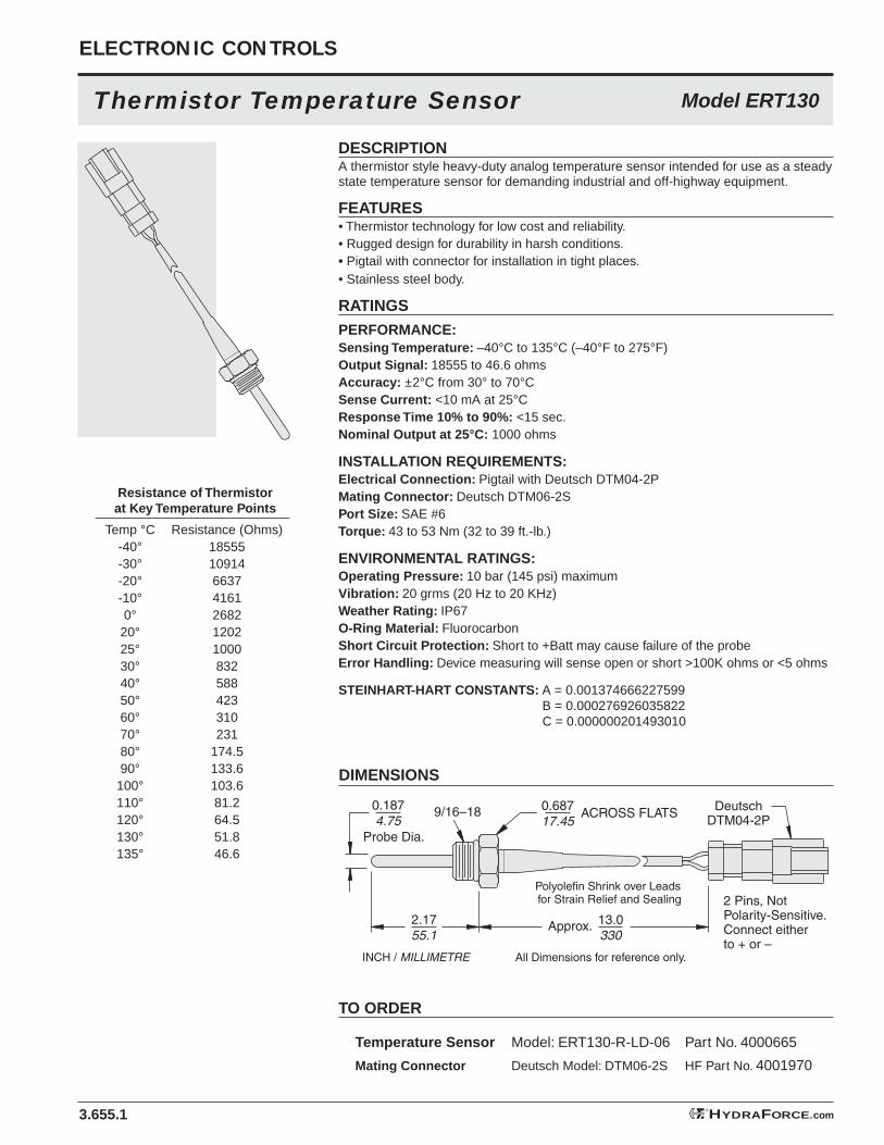
DESCRIPTIONA thermistor style heavy-duty analog temperature sensor intended for use as a steady state temperature sensor for demanding industrial and off-highway equipment.
FEATURES• Thermistor technology for low cost and reliability.• Rugged design for durability in harsh conditions.• Pigtail with connector for installation in tight places.• Stainless steel body.
RATINGS
PERFORMANCE:Sensing Temperature: –40°C to 135°C (–40°F to 275°F)Output Signal: 18555 to 46.6 ohmsAccuracy: ±2°C from 30° to 70°CSense Current: <10 mA at 25°CResponse Time 10% to 90%: <15 sec.Nominal Output at 25°C: 1000 ohms
INSTALLATION REQUIREMENTS:Electrical Connection: Pigtail with Deutsch DTM04-2PMating Connector: Deutsch DTM06-2SPort Size: SAE #6Torque: 43 to 53 Nm (32 to 39 ft.-lb.)
ENVIRONMENTAL RATINGS:Operating Pressure: 10 bar (145 psi) maximumVibration: 20 grms (20 Hz to 20 KHz)Weather Rating: IP67O-Ring Material: FluorocarbonShort Circuit Protection: Short to +Batt may cause failure of the probeError Handling: Device measuring will sense open or short >100K ohms or <5 ohms
STEINHART-HART CONSTANTS: A = 0.001374666227599 B = 0.000276926035822 C = 0.000000201493010
Thermistor Temperature Sensor
DIMENSIONS
TO ORDER
Temperature Sensor Model: ERT130-R-LD-06 Part No. 4000665
Mating Connector Deutsch Model: DTM06-2S HF Part No. 4001970
Resistance of Thermistor at Key Temperature Points
Temp °C Resistance (Ohms) -40° 18555 -30° 10914 -20° 6637 -10° 4161 0° 2682 20° 1202 25° 1000 30° 832 40° 588 50° 423 60° 310 70° 231 80° 174.5 90° 133.6 100° 103.6 110° 81.2 120° 64.5 130° 51.8 135° 46.6
Model ERT130
9/16–18
2 Pins, Not Polarity-Sensitive. Connect either to + or –
DeutschDTM04-2P
0.1874.75
Probe Dia.
ACROSS FLATS
Polyolefin Shrink over Leads for Strain Relief and Sealing
0.68717.45
13.0330
Approx.2.1755.1
INCH / MILLIMETRE All Dimensions for reference only.
3.655.1
ELECTRONIC CONTROLS
HYDRAFORCE.com®
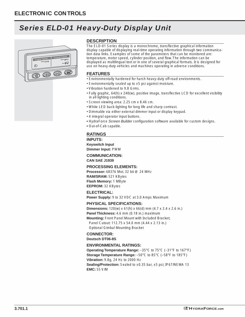
DESCRIPTIONThe ELD-01 Series display is a monochrome, transfl ective graphical information display capable of displaying real-time operating information through two communica-tion data links. Examples of some of the parameters that can be monitored are: temperature, motor speed, cylinder position, and fl ow. The information can be displayed as multilingual text or in one of several graphical formats. It is designed for use on heavy-duty vehicles and machines operating in adverse conditions.
FEATURES• Environmentally hardened for harsh heavy-duty off-road environments.• Environmentally sealed up to ±5 psi against moisture.• Vibration hardened to 9.8 Grms.• Fully graphic, 64(h) x 240(w), positive image, transfl ective LCD for excellent visibility
in all lighting conditions.• Screen viewing area: 2.25 cm x 8.46 cm.• White LED back-lighting for long life and sharp contrast.• Dimmable via either external dimmer input or display keypad.• 4 integral operator input buttons.• HydraForce Screen Builder confi guration software available for custom designs.• Out-of-Cab capable.
RATINGSINPUTS:Keyswitch InputDimmer Input: PWM
COMMUNICATION:CAN SAE J1939
PROCESSING ELEMENTS:Processor: 68376 Mot. 32 bit @ 24 MHzRAM/SRAM: 521 KBytesFlash Memory: 1 MByteEEPROM: 32 KBytes
ELECTRICAL:Power Supply: 9 to 32 VDC at 3.0 Amps Maximum
PHYSICAL SPECIFICATIONS:Dimensions: 120(w) x 61(h) x 66(d) mm (4.7 x 2.4 x 2.6 in.)Panel Thickness: 4.6 mm (0.18 in.) maximumMounting: Front Panel Mount with Included Bracket; Panel Cutout: 112.75 x 54.0 mm (4.44 x 2.13 in.) Optional Gimbal Mounting Bracket
CONNECTOR:Deutsch DT06-8S
ENVIRONMENTAL RATINGS:Operating Temperature Range: –35°C to 75°C (–31°F to 167°F)Storage Temperature Range: –50°C to 85°C (–58°F to 185°F)Vibration: 9.8g, 24 Hz to 2000 HzSealing/Protection: Sealed to ±0.35 bar, ±5 psi; IP67/NEMA 13EMC: 55 V/M
3.701.1
Series ELD-01 Heavy-Duty Display Unit
ELECTRONIC CONTROLS
Engine Speed
**** RPM**** MPH
Ground Speed
HYDRAFORCE.com®

3.701.2
DIMENSIONS
TO ORDER Backlighting Software Part No.
White None* 4000717
Series ELD-01 Heavy-Duty Display Unit
Pin Function
1 Battery 2 Ground 3 Keyswitch 4 PWM Input 5 Not Used 6 Not Used 7 CAN Hi 8 CAN Lo
PINOUT
Accessories:
*Screen Builder Confi guration Software: Part No. 4100000
Gasket: Part No. 4000947
Gimbal Mounting Bracket: Part No. 4000948
Mating Connector: Part No. 4001955
4.70119.5 Pin 1
Pin 8
All Dimensionsfor Reference Only.
3.3860.5
2.6066.0 2.20
56.0
4.41112.0
INCHMILLIMETRE
2.0852.9
Connector
J1939 DIAGNOSTIC SCREENS
Built-In Diagnostics with Automatic Interrupt:Engine Messages: Fuel, Filters, Injectors, Coolant, Lubrication, Speed, RPM, ExhaustTransmission & Driveline Messages: LubricationElectrical System Messages: Voltage, Load, Sensor Voltages
Priority Messaging: Note that this display is programmed to present certain J1939 messages immediately when installed, and when sensors trigger a serious fault or imminent failure condi-tion, ie. engine temperature, fuel system failure, et.al. These messages will displace any other active messages displayed at the time. This priority is preprogrammed into the display. For a list of these standard J1939 set messages, consult factory.
®HYDRAFORCE
HYDRAFORCE.com®

3.706.1
ELECTRONIC CONTROLS
ELD-06 2in. Backlighted LCD w/J1939 Data Link
HYDRAFORCE.com®
DESCRIPTIONA heavy-duty, stand-alone, 2-inch, 2 x 8 character display module that can be con-nected to an SAE J1939 (CAN) data bus and is sealed to IP65 standards. Displayed data can originate with the vehicle’s data bus. Backlighting is green/yellow and there are three status LEDs: green, red and amber. There are three, amber backlighted keys. This display unit is well-suited for use in mobile, heavy-duty and off-highway vehicles and equipment.
FEATURES• 2 x 8 character, backlighted, liquid crystal display.• Addressable Keys and LEDs• Three-button backlighted user interface buttons with tactile feel.• Three LED warning indicators, hidden when off.• Buzzer available for alert and high priority messages.• 9 to 60 VDC operation.
RATINGSCOMMUNICATION: CAN SAE J1939
ELECTRICAL:Power Supply: 9 to 60 VDC at 200 mAProtection: –24V ReverseData Bus: SAE J1939 (CAN)Connector: M12, 5-Pin
DISPLAY:Type: Positive, Transfl ective, FSTNAperture: 1.375" W by 0.50" HViewing Angle: 12:00Icon Colors: Green, Red and AmberScreen Color: Green/YellowKey Backlight Color: Amber
DIMENSIONS
TO ORDER
Model No: 4204540
Confi guration Kit: Part No. 4204540
Gasket: Part No. 4000706
Installation Cable for System Integration: Model M12-5 Cable with Harness Assembly, Part No. 4000680
Mating Connector, DTM04-6S:Part No. 4001973
Video Electronic 100-Style Mount (Industry Standard)
ENVIRONMENTAL RATINGS:Operating Temperature:
–20°C to +70°CImmersion: IP65
MATERIAL:Housing and Bezel: Black
polycarbonate ABS Plastic
2.0552
2.3660
DIA.
DIA.
1.1228.5
1.9148.5
0.3910 Recommended Panel Cutout
All Dimensions for Reference
Only.
INCHMILLIMETRE
Pin No.12345
FunctionGroundVcc 9 to 60 VDCCAN GroundCAN_HCAN_L
2.0752.5
1 3
52
4
DIA.2.09
53.0

3.707.1
®HYDRAFORCE
HYDRAFORCE.com®
ELD-07 5in. Square LCD Display w/J1939 Data Link
DESCRIPTIONAn all-purpose heavy-duty display unit with a 5-inch-square face. The programmable, graphical display can visualize data on the CAN bus. There are eight switches, a buzzer, LED backlight for the keyboard and a 320 x 240 color LCD display. Data can be exchanged via CAN bus. This display unit is well-suited for use in heavy-duty mobile, industrial and off-highway vehicles and equipment.
FEATURES• Programmable, graphical, backlighted LCD display.• Addressable Keys and LEDs• Eight backlighted user interface buttons.• 9 to 60 VDC operation.
RATINGSCOMMUNICATION: CAN SAE J1939
ELECTRICAL:Power Supply: 9 to 60 VDCCurrent Consumption: Less than 800mA @ 24 VDCFlash Memory: 4 MB; SRAM: 256 KB; EEPROM: 64 KBData Bus: SAE J1939 (CAN)Connector: M12, 5-Pin
DISPLAY:Type: Color LCD, 320 x 240 pixels (1/4 VGA) with dimmable backlightingLED: 1 LEDOperator keys: Eight, LED illuminated switches
ENVIRONMENTAL RATINGS:Operating Temperature: –30°C to +65°CSealed against Contamination: IP67
MATERIAL:Housing: Aluminum; Bezel and Face: Black polycarbonate ABS Plastic
DIMENSIONS
TO ORDER
Model No: 4000704Confi guration Kit: Part No. 4206310
Installation Cable for System Integration: Model M12-5 Cable with Harness Assembly, Part No. 4000680
Mating Connector, DTM04-6S:Part No. 4001973
Video Electronic 100-Style Mount(Industry Standard)
All Dimensions for Reference Only.
INCHMILLIMETRE
Pin No.12345
FunctionGroundVcc 9 to 60 VDCCAN GroundCAN_HCAN_L
1 3
52
4
RecommendedPanel Cutout:
Width: 5.945" ±0.008"151mm ±0.2mm
Height: 5.512" ±0.008"140mm ±0.02mm
Corner Radius: 0.04"1mm
6.30160
5.91150
4.11104.3
6.30160
2.0351.5
1.8647.2
0.3910
5.46138.6
3.0677.8

3.708.1
ELECTRONIC CONTROLS
ELD-08 5.7in. Mono LCD Display w/J1939 Data Link
HYDRAFORCE.com®
DESCRIPTIONA heavy-duty, stand-alone, 5.7-inch, monochrome LCD display module that can be connected to an SAE J1939 (CAN) data bus and is sealed to IP67 standards. Displayed data can originate with the vehicle’s data bus. There are four backlit buttons. This display unit is well-suited for use in mobile, heavy-duty and off-highway vehicles and equipment.
FEATURES• 320 x 240 pixel, transfl ective, liquid crystal display.• Four addressable backlit buttons.• 9 to 60 VDC operation.
RATINGSCOMMUNICATION: CAN SAE J1939
ELECTRICAL:Power Supply: 9 to 60 VDC;Current Consumption: 210mA @ 24 VDCProtection: –24V ReverseData Bus: SAE J1939 (CAN)Memory: Program Flash: 256KB; Data Flash: 1MB; EEPROM: 64KB; SRAM: 256KBConnector: M12, 5-Pin
DISPLAY:Type: Positive, Transfl ective, FSTNViewing Angle: 12:00Backlighting: Four Buttons
ENVIRONMENTAL RATINGS:Operating Temperature: –20°C to +65°CSealed against Contamination: IP67
MATERIAL:Housing and Bezel: Black polycarbonate ABS Plastic front; Aluminum Housing
DIMENSIONS
All Dimensions for Reference Only.
INCHMILLIMETRE
1.9750
0.246
3.5891
7.36187
7.05179
2.4462
2.9575
2.9575
5.91150
4.69119
Pin No.12345
FunctionGroundVcc 9 to 60 VDCCAN GroundCAN_HCAN_L
1 3
52
4
RecommendedPanel Cutout:
Width: 6.85"/174mm
Height: 5.71"/145mm
Corner Radius:0.177"/4.5mm
TO ORDER
Model No: 4000701Confi guration Kit: Part No. 4206310
Installation Cable for System Integration: Model M12-5 Cable with Harness Assembly, Part No. 4000680
Mating Connector, DTM04-6S:Part No. 4001973
Video Electronic 100-Style Mount(Industry Standard)