Embed Size (px)
Citation preview
505 International Journal of Control Theory and Applications
H¥ Loop Shaping Controller design for regulating Air Fuel Ratio and Speed of an SI Engine
H Loop Shaping Controller design for regulating Air Fuel Ratio andSpeed of an SI Engine
T.Viveka, K. Mohaideen Abdul Kadharb and S. Baskarc
aAssistant Professor, Department of Mechatronics, E-mail: [email protected] Professor, Department of Electrical and Electronics Engg., E-mail: [email protected],c Thiagarajar College of Engineering, Madurai, Tamilnadu, Indiab Associate Professor, Dr. Mahalingam College of Engineering and Technology, IndiaE-mail: [email protected]
Abstract: This paper discuss about developing Multi Input Multi Output (MIMO) Robust H� controller for regulationAir fuel ratio (�) and speed of an SI Engine based on H� Loop shaping approach in normal operating range. MeanValue Engine Model has been used for validating the controller performance. Developed H� controller is a 3x3transfer function matrix of 13th order. Robustness of the system is verified by testing the closed loop system with loaddisturbance, Parameter variations and noise. Results show that under H
” controller, SI engine performs better when
subjected to load disturbance, Parameter variations and noise.
Keywords: SI Engine control, Robust control,Air fuel ratio, speed, H” Loop Shaping.
INTRODUCTION
SI engine is a highly nonlinear system which demands a good controller design for regulating its output againstdisturbances. Due to stringent emission norms of automotive standards it has become mandatory to maintain Airfuel ratio(AFR) at stiochiometric value and regulate speed at constant value. SI Engine works in idle operatingmode and Normal operating Mode. This paper considers engine working in normal operating mode. ElbertHendricks et al. developed Mean value SI Engine model for control studies [1]. Christopher H onder et al. [2]discuss about developing multivariable speed and Air fuel ratio control of SI Engine based on LQG/LQR method.Hendricks et al. [3] describes developing H� controller based on iterative process for controlling Air fuel ratio ofan SI engine. Dingli Yu et al. [4] validate Robustness of an engine model that is developed using RBF NeuralNetworks.
After a short introduction this paper continues with section II describes governing equations of MIMOEngine Model. Section III discusses about development of H� Loop shaping controller. Section IV assessRobustness of SI engine with load disturbance parameter variation and noise.
International Journal of Control Theory and Applications 506
T.Vivek, K. Mohaideen Abdul Kadhar and S. Baskar
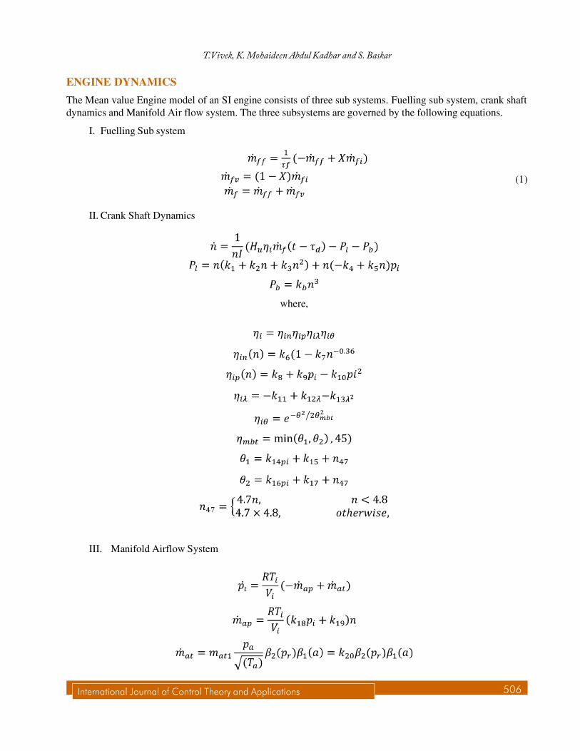
ENGINE DYNAMICS
The Mean value Engine model of an SI engine consists of three sub systems. Fuelling sub system, crank shaftdynamics and Manifold Air flow system. The three subsystems are governed by the following equations.
I. Fuelling Sub system
(1)
II. Crank Shaft Dynamics
where,
III. Manifold Airflow System
507 International Journal of Control Theory and Applications
H¥ Loop Shaping Controller design for regulating Air Fuel Ratio and Speed of an SI Engine
The relationship between Lambda and states of the state space model is given y equation 2.
(2)
H LOOP SHAPING CONTROLLER DESIGN
Controller Design
H� loop shaping controller is well known for its effective methodology in designing robust controllers. In thismethod, the plant is shaped by using a pre and post compensators namely W1 and W2 (i.e., Gs=W1GW2),respectively. Once the desired loop shape is achieved, a stabilizing controller (K�) is achieved by minimizing the�-norm of the closed loop system (||Tzw||�) from the disturbances d1 and d2 to the outputs z1 and z2. The �-normof the closed loop system is given in the equation (3).
(3)
where, � represents the stability margin of the closed loop system, Gs is the shaped system, Msis the co-primefactor of the shaped system. Then, the final controller is constructed by combining the stabilizing controller (K”)with W1 and W2 as in the equation (4).
K = W1 K�W2 (4)
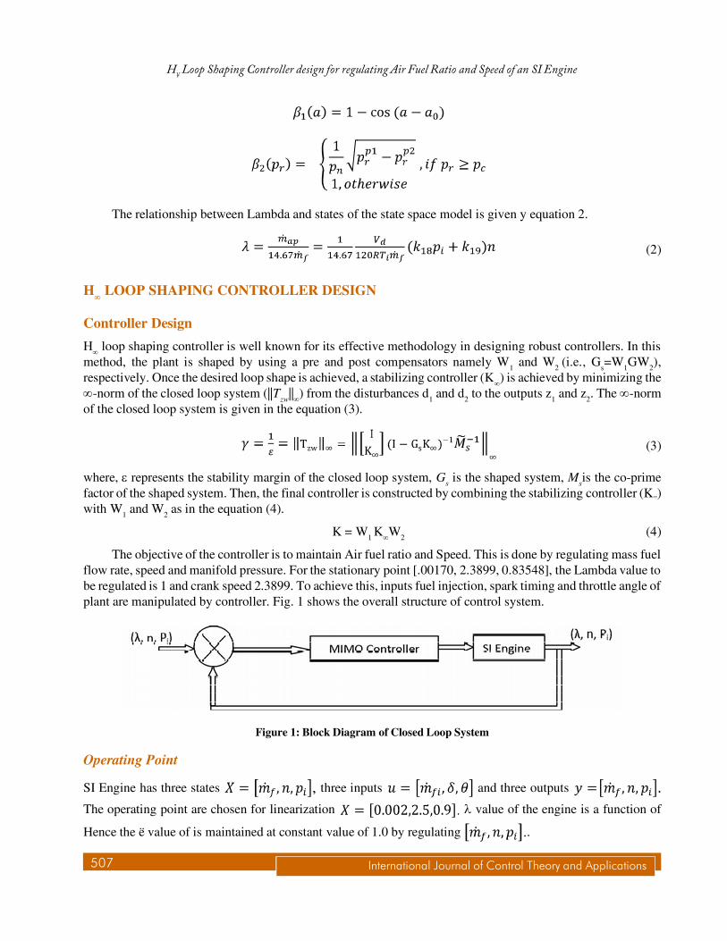
The objective of the controller is to maintain Air fuel ratio and Speed. This is done by regulating mass fuelflow rate, speed and manifold pressure. For the stationary point [.00170, 2.3899, 0.83548], the Lambda value tobe regulated is 1 and crank speed 2.3899. To achieve this, inputs fuel injection, spark timing and throttle angle ofplant are manipulated by controller. Fig. 1 shows the overall structure of control system.
Figure 1: Block Diagram of Closed Loop System
Operating Point
SI Engine has three states three inputs and three outputs
The operating point are chosen for linearization � value of the engine is a function of
Hence the ë value of is maintained at constant value of 1.0 by regulating .
International Journal of Control Theory and Applications 508
T.Vivek, K. Mohaideen Abdul Kadhar and S. Baskar
The linearised state space model is given by.
Conformity of the state space model to non linear equations was verified. This is done by giving incrementalinput to the model and adding the obtained output with operating point. The same incremental input is given tothe non linear equations. Both the outputs were compared and found to be nearly same.
Weighting function selection:
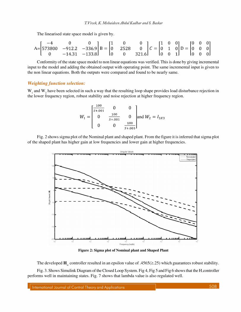
W1 and W2 have been selected in such a way that the resulting loop shape provides load disturbance rejection inthe lower frequency region, robust stability and noise rejection at higher frequency region.
Fig. 2 shows sigma plot of the Nominal plant and shaped plant. From the figure it is inferred that sigma plotof the shaped plant has higher gain at low frequencies and lower gain at higher frequencies.
Figure 2: Sigma plot of Nominal plant and Shaped Plant
The developed H controller resulted in an epsilon value of .4565(�.25) which guarantees robust stability.
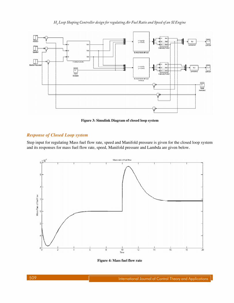
Fig. 3. Shows Simulink Diagram of the Closed Loop System. Fig 4, Fig 5 and Fig 6 shows that the H”controllerperforms well in maintaining states. Fig. 7 shows that lambda value is also regulated well.
509 International Journal of Control Theory and Applications
H¥ Loop Shaping Controller design for regulating Air Fuel Ratio and Speed of an SI Engine
Response of Closed Loop system
Step input for regulating Mass fuel flow rate, speed and Manifold pressure is given for the closed loop systemand its responses for mass fuel flow rate, speed, Manifold pressure and Lambda are given below.
Figure 3: Simulink Diagram of closed loop system
Figure 4: Mass fuel flow rate
International Journal of Control Theory and Applications 510
T.Vivek, K. Mohaideen Abdul Kadhar and S. Baskar
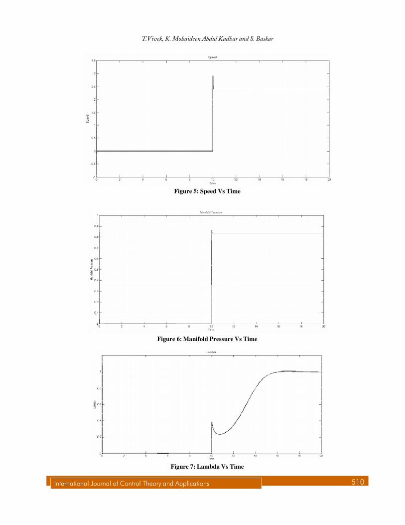
Figure 5: Speed Vs Time
Figure 6: Manifold Pressure Vs Time
Figure 7: Lambda Vs Time
511 International Journal of Control Theory and Applications
H¥ Loop Shaping Controller design for regulating Air Fuel Ratio and Speed of an SI Engine
Robustness Verification
(a) Load Disturbance
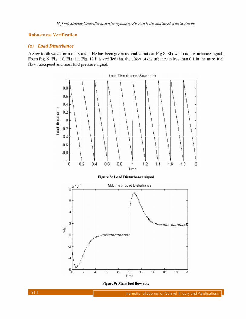
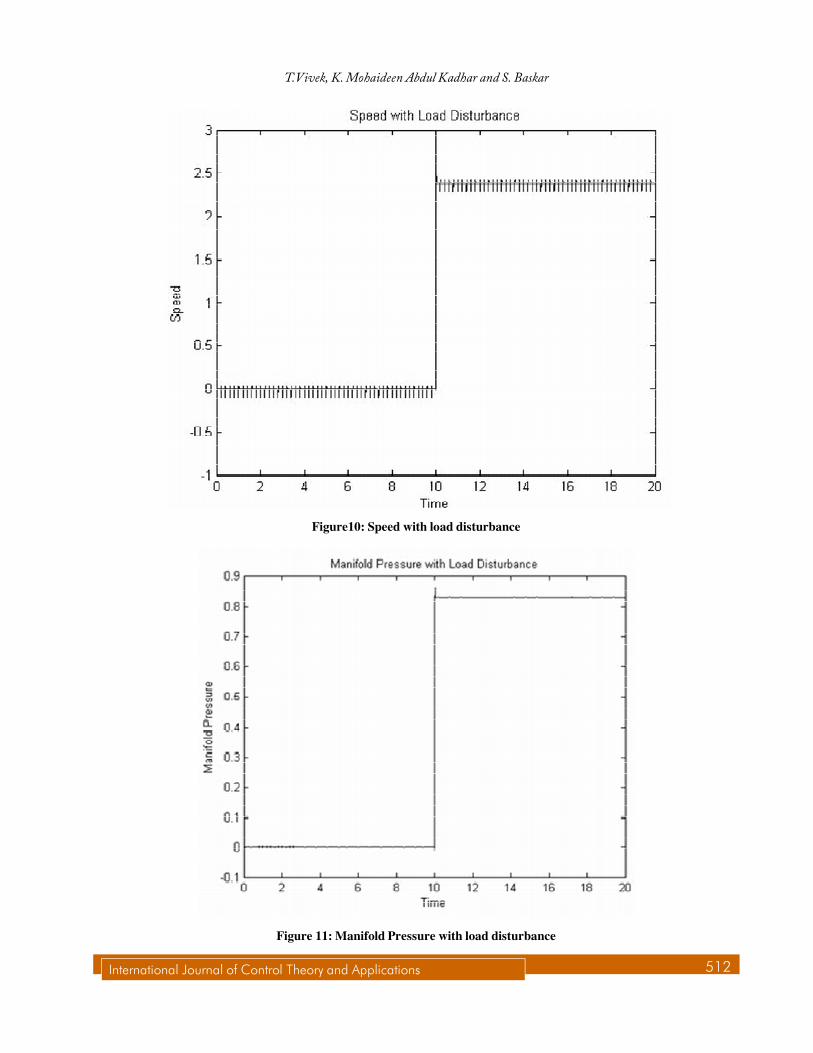
A Saw tooth wave form of 1v and 5 Hz has been given as load variation. Fig 8. Shows Load disturbance signal.From Fig. 9, Fig. 10, Fig. 11, Fig. 12 it is verified that the effect of disturbance is less than 0.1 in the mass fuelflow rate,speed and manifold pressure signal.
Figure 8: Load Disturbance signal
Figure 9: Mass fuel flow rate
International Journal of Control Theory and Applications 512
T.Vivek, K. Mohaideen Abdul Kadhar and S. Baskar
Figure10: Speed with load disturbance
Figure 11: Manifold Pressure with load disturbance
513 International Journal of Control Theory and Applications
H¥ Loop Shaping Controller design for regulating Air Fuel Ratio and Speed of an SI Engine
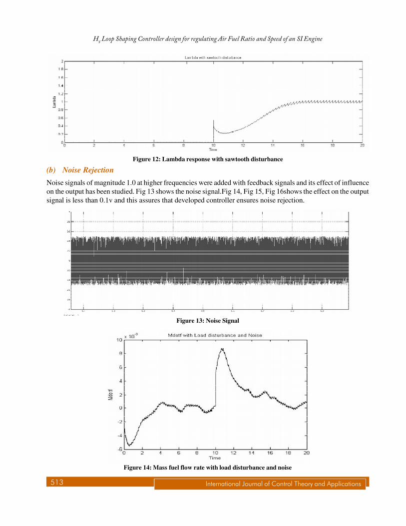
(b) Noise Rejection
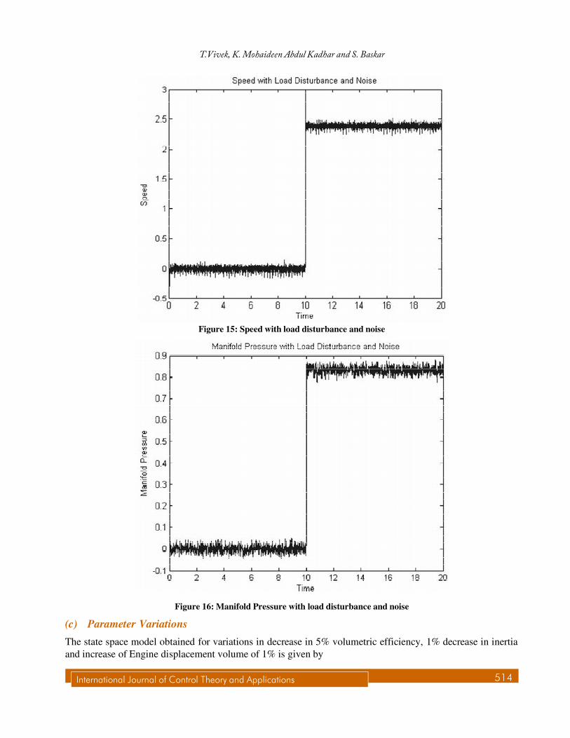
Noise signals of magnitude 1.0 at higher frequencies were added with feedback signals and its effect of influenceon the output has been studied. Fig 13 shows the noise signal.Fig 14, Fig 15, Fig 16shows the effect on the outputsignal is less than 0.1v and this assures that developed controller ensures noise rejection.
Figure 12: Lambda response with sawtooth disturbance
Figure 13: Noise Signal
Figure 14: Mass fuel flow rate with load disturbance and noise
International Journal of Control Theory and Applications 514
T.Vivek, K. Mohaideen Abdul Kadhar and S. Baskar
Figure 16: Manifold Pressure with load disturbance and noise
Figure 15: Speed with load disturbance and noise
(c) Parameter Variations
The state space model obtained for variations in decrease in 5% volumetric efficiency, 1% decrease in inertiaand increase of Engine displacement volume of 1% is given by
515 International Journal of Control Theory and Applications
H¥ Loop Shaping Controller design for regulating Air Fuel Ratio and Speed of an SI Engine
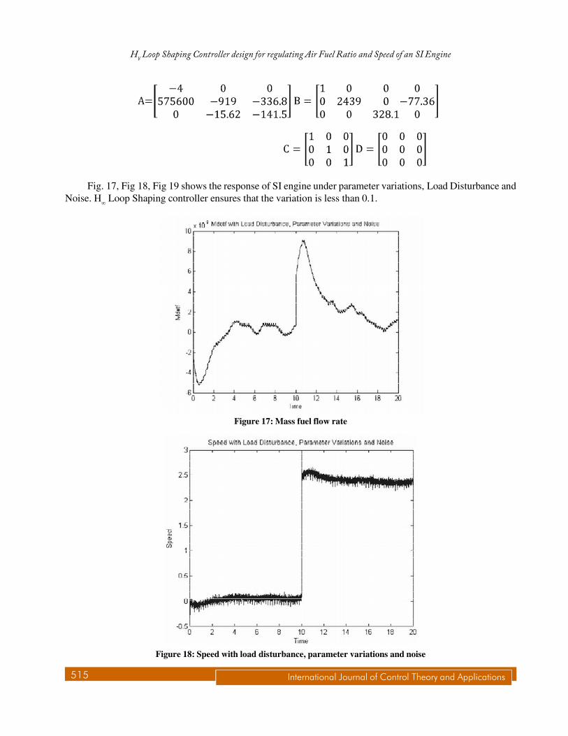
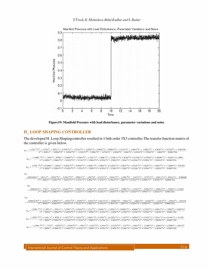
Fig. 17, Fig 18, Fig 19 shows the response of SI engine under parameter variations, Load Disturbance andNoise. H� Loop Shaping controller ensures that the variation is less than 0.1.
Figure 17: Mass fuel flow rate
Figure 18: Speed with load disturbance, parameter variations and noise
International Journal of Control Theory and Applications 516
T.Vivek, K. Mohaideen Abdul Kadhar and S. Baskar
H LOOP SHAPING CONTROLLER
The developed H” Loop Shapingcontroller resulted in 13nth order 3X3 controller.The transfer function matrix ofthe controller is given below.
Figure19: Manifold Pressure with load disturbance, parameter variations and noise
517 International Journal of Control Theory and Applications
H¥ Loop Shaping Controller design for regulating Air Fuel Ratio and Speed of an SI Engine
Hardware in Loop Simulation and Rapid Controller Prototyping
Hardware in loop Simulation
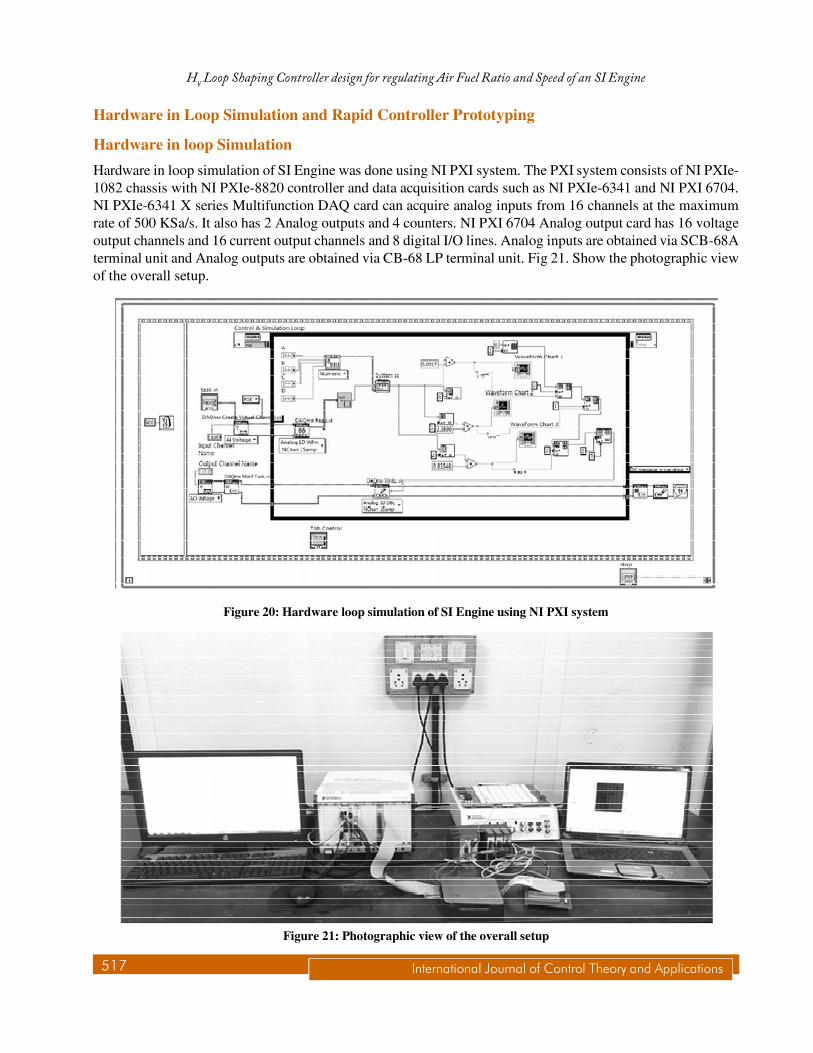
Hardware in loop simulation of SI Engine was done using NI PXI system. The PXI system consists of NI PXIe-1082 chassis with NI PXIe-8820 controller and data acquisition cards such as NI PXIe-6341 and NI PXI 6704.NI PXIe-6341 X series Multifunction DAQ card can acquire analog inputs from 16 channels at the maximumrate of 500 KSa/s. It also has 2 Analog outputs and 4 counters. NI PXI 6704 Analog output card has 16 voltageoutput channels and 16 current output channels and 8 digital I/O lines. Analog inputs are obtained via SCB-68Aterminal unit and Analog outputs are obtained via CB-68 LP terminal unit. Fig 21. Show the photographic viewof the overall setup.
Figure 20: Hardware loop simulation of SI Engine using NI PXI system
Figure 21: Photographic view of the overall setup
International Journal of Control Theory and Applications 518
T.Vivek, K. Mohaideen Abdul Kadhar and S. Baskar
Rapid Controller Prototyping
NI Compact RIO is one of the hardware platforms that combine the power of Processor and FPGA technology.While processors run computations in sequence FPGAs can run computations in parallel.cRIO consists of NIcRIO chassis 9014, Analog input Modules cRIO-9215, Analog current output Modules NI-9265 and Digital I/OModules NI-9472.Rapid controller prototyping needs one time critical loop that implements controller runningon real time target .The set point for regulating three output variables are given in cRIO.
Analog input such as Speed, Lambda and Manifold pressure are obtained using cRIO-9215. Output fromPID Controller such as fuel injection, spark timing and throttle angleis sent through NI 9265. MIMO H infinityloop shaping PID Controller is implemented using cRIO as 3X3 matrix.
Parameter of Engine
The simulations are carried out for a 1275cc British Leyland engine for which data have been reported[24],[25].The values of the parameters used in the simulations are:
I = (2�/60)2× 0.5 kg` 0m2 , �f= 0.25,X = 0.22, Vi =646 × 10–6 , Hu= 4.3 × 10⁴ , Vd= 1.275, R = 287 × 10–5 , Ti= 308,Ta= 297, Pa= 1.013, k1 = 1.673, k2 =0.272, k3 = 0.0135, k4 = 0.969, k5 = 0.206, k6=0.558, k7 =0.392, k8 = 0.9301,k9 = 0.2154, k10 = 0.1657, k11=1.025 ,k12=4.5 ,k13=2.5 ,k14 = 47.31,k15 = 2.6214, k16 = –56.55, k17 = 57.34, K18=0.952,k19=0.075, k20 = 7.32Pa/�Ta .
CONCLUSION
In this work H” Loop Shaping controller has been developed for regulating AFR and Speed of an SI Engine.Robustness of the controller is evaluated for Load disturbance, Parameter Variations and noise. The results showthat the variation in the output is very less under the above influences. But the developed controller resulted in a3X3 Transfer function matrix of order 13.In the future work it is proposed to develop fixed structure controllerusing H” Loop Shaping approach.
REFERENCES
[1] Hendricks E. and Sorensen S.C.,”Mean value modeling of SI Engines”, SAE paper 900616, 1990.
[2] Onder C. H. and Geering H. P., “Model-Based Multivariable Speed and Air-to-Fuel Ratio Control of an SI Engine,” SAEPaper No. 930859, 1993.
[3] Christian winge vigild, Karsten P.H. Anderson and Elbert Hendricks, Micheal struwe “Towards Robust H” Control of an SIEngines Air/Fuel Ratio”, SAE Technical Paper 1999-01-0854, 1999.
[4] Mahavir Singh Sangha , Dingli Yu, J.Barry Gomm, “Robustness assessment and Adaptive FDI for car engines”, Internationaljournal of Automation and Computing, vol. 5, Issue. 2, pp. 109-118, April 2008.
[5] Huajin Tang, Larry Werg,Zhao Yang Dong, Rui Yan, “Adaptive and Learning control for SI Engine Model withuncertainties”, IEEE/ASME Transaction on Mechatronics, vol. 14, no. 1, pp. 93-104, 2009.
[6] Raymond C. Turin, Rong Zhang, Man-Feng Chang., “Systematic model based Engine control design”, Electronic EngineControls, SAE Paper Number: 20081508,pp-413-424Apr, 2008.
[7] Sigurd Skogestad, Ian postlethwaite, “Multi variable Feedback control, Analysis and Design”, John wiley & sons, 2001.
[8] McFarlane,D.C., and Glover,K.,” A loop shaping design procedure using H” synthesis”, IEEE Trans. On Automatic Control.37 (6), 759–69, 1992.
[9] Lino Guzzella and Christopher H. Onder, “Introduction to Modeling and Control of Internal Combustion Engine Systems,2nd edition,Springer Berlin Heidelberg, 2010, ch.4.3,pp. 239-244.
[10] Kwakernaak H, “ Robust control and H”optimization-Tutorial”, Automatica, vol. 29, no. 2, pp. 255-273, 1993.
519 International Journal of Control Theory and Applications
H¥ Loop Shaping Controller design for regulating Air Fuel Ratio and Speed of an SI Engine
[11] N.Singh, R.Vig, J.K.Sharma, “ICE Idle Speed Control using fuzzy idle”, SAE Paper Number: 2002-01-1151,Apr, 2001.
[12] E.Hendricks, A chevalier, M.Jensen, S.C.Sorenson, D.Trumpy and J.Asik, “Modelling of the intake manifold fillingdynamics”, SAE Tech Paper, PP 122-146, 1996, Paper 960037.
[13] M.K.Khan and S.K. Spurgeon, “MIMO control of an IC engine using dynamic sliding modes” in Proc .Intell.syst.control2003, vol 388, PP132-137.


![Increasing the Electrolyte Capacity of Alkaline Zn-Air Fuel ......energy output.[5-8] Of all metal-air batteries/fuel cells that are currently under development, Zn-air batteries/fuel](https://img.pdfslide.net/doc/110x75/60c8a911cae270223f2032f5/increasing-the-electrolyte-capacity-of-alkaline-zn-air-fuel-energy-output5-8.jpg)