Embed Size (px)
Citation preview

H. MAINAUD DURAND
on behalf of the CLIC active pre-alignement team
QD0 and BDS pre-alignment

2
SUMMARY
BDS pre-alignment requirements and strategy
MDI area requirements and strategy:o Determination of the position of QD0 w.r.t other components of the
BDSo Left w.r.t right sideo Monitoring of QD0

3
BDS: requirements concerning pre-alignment
Within +/- 0.1 mm (1s)
Active pre-alignment Beam based alignment
Beam based feedbacksWithin a few microns
Active pre-alignment
=Determination of the position of the components in a
general coordinate system thanks to alignment systems
Re-adjustment thanks to actuators
+
The zero of each component will be included in a cylinder with a radius of a few microns:
10 µm (BDS components)
(14 μm / 17 μm for main linac components)
Adjustment required: step size below 1 µm, 5 DOF
Mechanical pre-alignment
PRE-ALIGNMENT (beam off)
CLIC
Error of misalignment of the fiducials (1σ): 0.02 mm over 200 m
Fiducialisation: 0.05 mm rms
ILC

4
BDS: strategy
Solution proposed
Installation and determination of the Survey network
Transfer of reference into tunnel
Installation and determination of the tunnel network
Absolute alignment of the elements
Relative alignment of the elements
Active prealignment
Control and maintenance of the alignment

5
BDS: strategy
Solution proposed
Installation and determination of the Survey network
Transfer of reference into tunnel
Installation and determination of the tunnel network
Combination of 3D triangulation and trilateration coupled with measurements on vertical plumb wires
Methods validated on an LHC pit in 2010 (depth of 65 m): precision of 0.1 mm and accuracy of 0.5 mm
Hypothesis considered for CLIC: absolute position at the bottom of each pit: ± 2 mm (depth > 100 m)
Distance < 2.5 km
6
BDS: strategy
Solution proposed Absolute alignment of the elements
Relative alignment of the elements
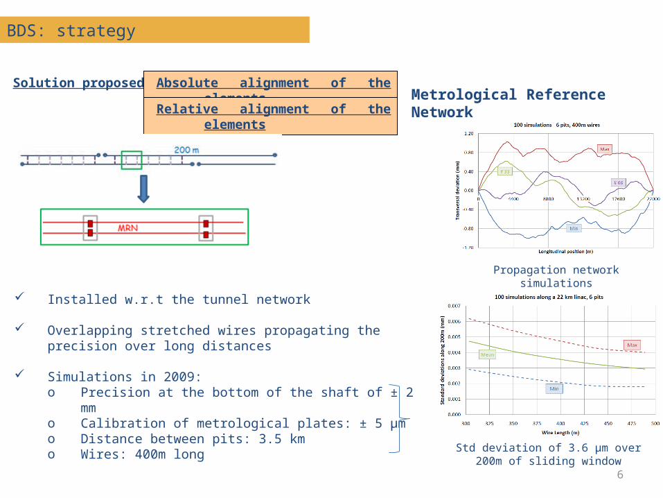
Metrological Reference Network
Installed w.r.t the tunnel network
Overlapping stretched wires propagating the precision over long distances
Simulations in 2009: o Precision at the bottom of the shaft of ± 2 mmo Calibration of metrological plates: ± 5 μmo Distance between pits: 3.5 kmo Wires: 400m long
Std deviation of 3.6 μm over 200m of sliding window
Propagation network simulations
7
BDS: strategy
Solution proposed Absolute alignment of the elements
Relative alignment of the elements
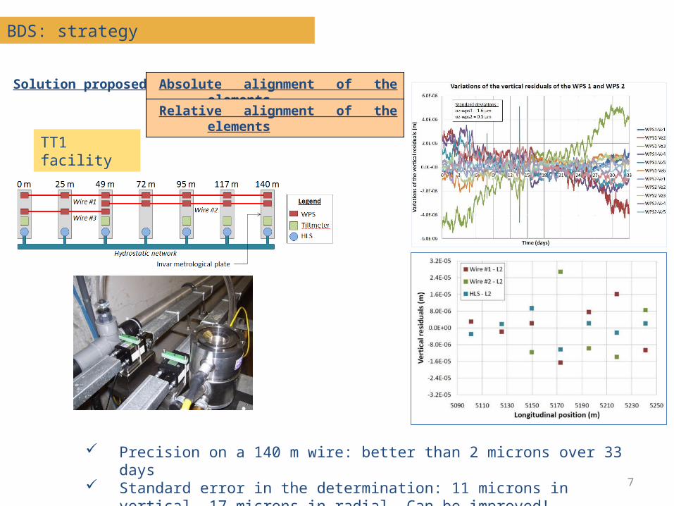
TT1 facility
Precision on a 140 m wire: better than 2 microns over 33 days Standard error in the determination: 11 microns in vertical, 17
microns in radial. Can be improved!
8
BDS: strategy
Solution proposed Absolute alignment of the elements
Relative alignment of the elements
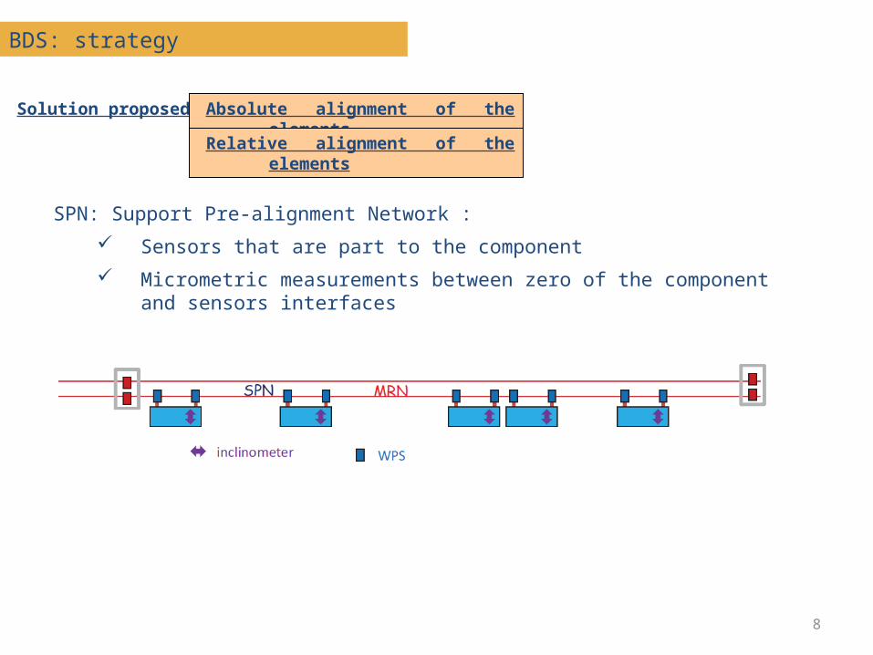
SPN: Support Pre-alignment Network :
Sensors that are part to the component
Micrometric measurements between zero of the component and sensors interfaces
9
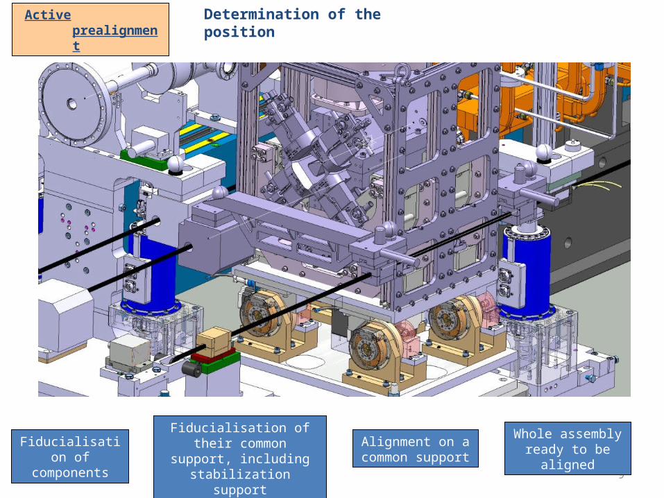
Fiducialisation of components
Fiducialisation of their common support,
including stabilization support
Alignment on a common support
Whole assembly ready to be
aligned
Active prealignment
Determination of the position
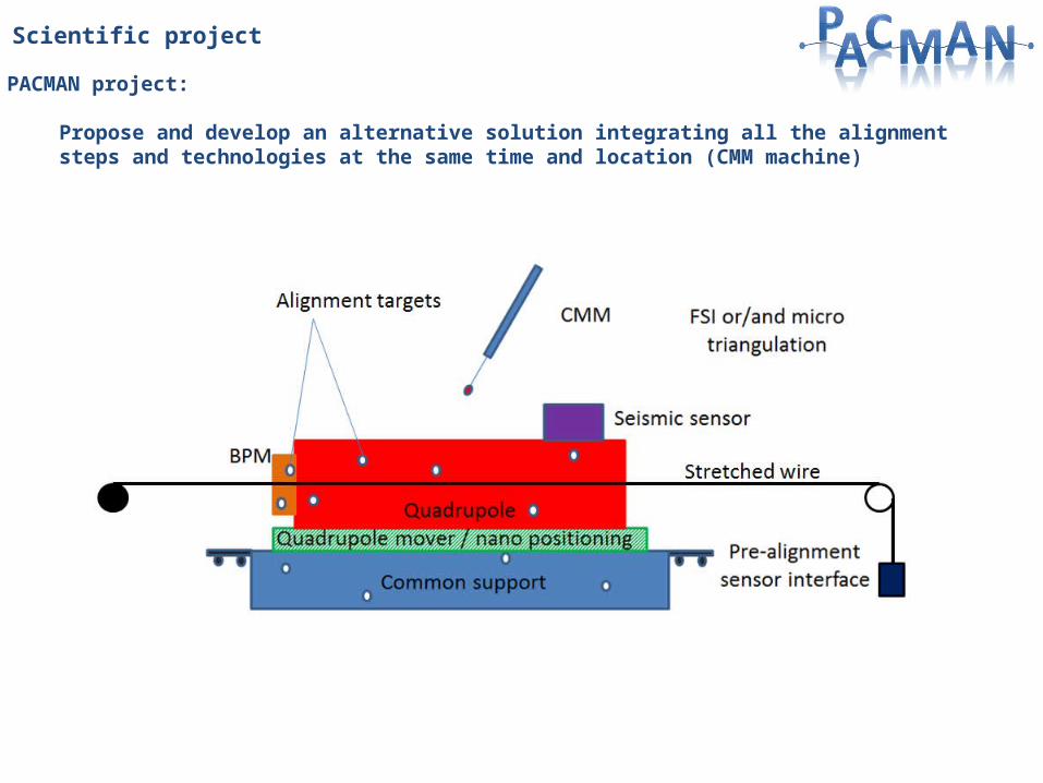
Scientific project
PACMAN project:
Propose and develop an alternative solution integrating all the alignment steps and technologies at the same time and location (CMM machine)

11
DMP ES
ELTOS IT
ETALON DE
METROLAB CH
SIGMAPHI FR
Cranfield University GB
ETH Zürich CH
LAPP FR
SYMME FR
University of Sannio IT
IFIC / FESIC ES
Delft University of Technology NL
Hexagon Metrology DE
National Instruments HU
TNO NL
Start date : 1/09/2013
Duration: 4 years
Marie Curie Initial Training Network (ITN):
Web site: http://cern.ch/pacman
Recruitment under way
Innovative Doctoral Program
CERN as host institution
10 PhD students
15 associated partners
12
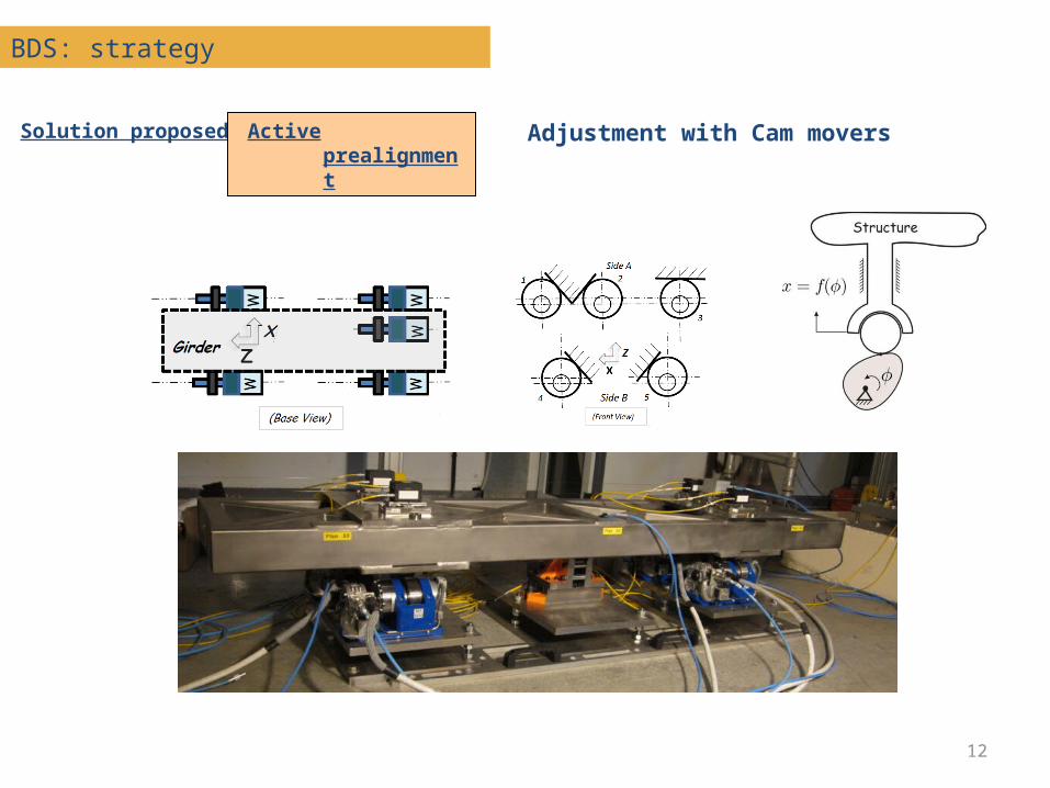
BDS: strategy
Solution proposed Active prealignment
Adjustment with Cam movers
13
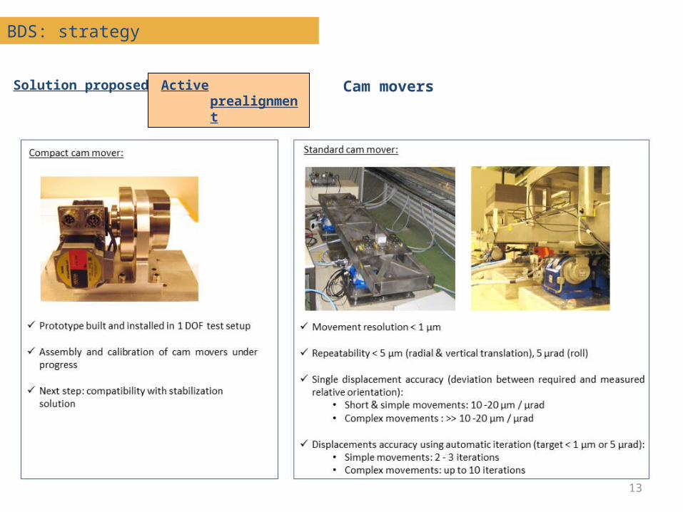
BDS: strategy
Solution proposed Active prealignment
Cam movers
14
SUMMARY
BDS alignment strategy: status and next steps
MDI area:o Determination of the position of QD0 w.r.t other
components of the BDSo Left w.r.t right sideo Monitoring of QD0o Detector w.r.t BDS geometry

15
MDI area
Determination of the position of QD0 w.r.t other components of the BDS (1)
Same solution than for BDS Main difference concerns the MRN network (due to lack of space):
o No overlapping of stretched wires in the last meterso No HLS system needed for the modeling of the sag, which will be extrapolated
Longitudinal position: use of sensors (capacitive, LVDT) to follow the relative position.
Strategy proposed :
Requirements :
Position of the zero of QD0 w.r.t ideal straight line of the 500 last meters of BDS: ± 10 μm rms (including fiducialisation) also needed for ILC (± 20 μm not including fiducialisation)
Longitudinal relative position between QD0 and QF1: ± 20 μm rms
16
MDI area
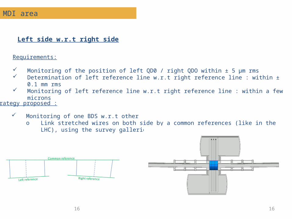
Left side w.r.t right side
16
Requirements:
Monitoring of the position of left QD0 / right QDO within ± 5 μm rms Determination of left reference line w.r.t right reference line : within ± 0.1 mm rms Monitoring of left reference line w.r.t right reference line : within a few microns
Monitoring of one BDS w.r.t othero Link stretched wires on both side by a common references (like in the LHC), using
the survey galleries
Strategy proposed :

1725 April 2012 MDI session at KILC12- Daegu, South Korea 17
Mini survey galleries
Survey mini galleries
18
MDI area
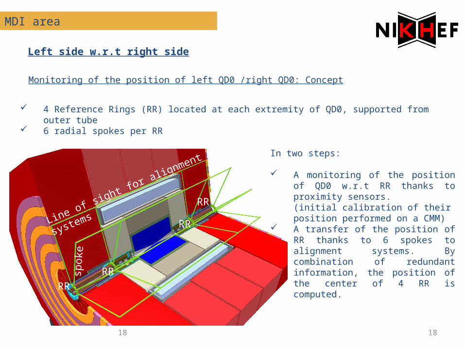
Left side w.r.t right side
18
Monitoring of the position of left QD0 /right QD0: Concept
4 Reference Rings (RR) located at each extremity of QD0, supported from outer tube 6 radial spokes per RR
RRRR
RR
RR
spoke
Line of sight for alignment
systems
In two steps:
A monitoring of the position of QD0 w.r.t RR thanks to proximity sensors.(initial calibration of their position performed on a CMM)
A transfer of the position of RR thanks to 6 spokes to alignment systems. By combination of redundant information, the position of the center of 4 RR is computed.

19
Transfer quality ~ 0.1 μm (12 dismounting /remounting)
Thermal expansion driven by granite thermal expansion, and confirm that the thermal expansion of zerodur is very small
Young modulus checked.
20
Summary
In the MDI area, 3 subjects are under study currently, common to CLIC and ILC:
The monitoring of the position of QD0, through a collaboration with NIKHEF
• Concept proposed• First tests performed on 1m long spokes• Sensors under validation on TBTM
Survey mini galleries• Concept proposed
The improvement of the fiducialisation process via PACMAN• 10 PhD students will start to work on the project beginning of 2014
In the BDS area, taking into consideration the very tight alignment tolerances for ILC, an active alignment will be needed. The solution proposed for CLIC could be applied:
Determination of the position of components using alignment sensors
Re-adjustment using cam movers.