Embed Size (px)
Citation preview
H-Max Series Drives IntelliPass®/IntelliDisconnect®
Frames 4-7
H-Max Series Drives
Important Notice – Please Read
The product discussed in this literature is subject to terms and conditions outlined in Eaton Electrical Inc. selling policies. The sole source governing the rights and remedies of any purchaser of this equipment is the relevant Eaton Electrical Inc. selling policy.
NO WARRANTIES, EXPRESS OR IMPLIED, INCLUDING WARRANTIES OF FITNESS FOR A PARTICULAR PURPOSE OR MERCHANTABILITY, OR WARRANTIES ARISING FROM COURSE OF DEALING OR USAGE OF TRADE, ARE MADE REGARDING THE INFORMATION, RECOMMENDATIONS AND DESCRIPTIONS CONTAINED HEREIN.
In no event will Eaton Electrical Inc. be responsible to the purchaser or user in contract, in tort (including negligence), strict liability or otherwise for any special, indirect, incidental or consequential damage or loss whatsoever, including but not limited to damage or loss of use of equipment, plant or power system, cost of capital, loss of power, additional expenses in the use of existing power facilities, or claims against the purchaser or user by its customers resulting from the use of the informa-tion, recommendations and descriptions contained herein. The information contained in this manual is subject to change without notice.
Safety
Read and follow all safety information shown in the H-Max installation Manual MN04008005E.
2
Important Notice – Please Read
H-Max Series Drives IntelliPass®/IntelliDisconnect® IL04008003E April 2013 www.eaton.com
Contents
INTRODUCTIONGeneral . . . . . . . . . . . . . . . . . . . . . . . . . . . . . . . . . . . . . . . . . . . . . . . . . . . . . . . . . . . . . . . . . . . . . . . . . . . . . . . . . . . . . . .4
Catalog / Style Numbering . . . . . . . . . . . . . . . . . . . . . . . . . . . . . . . . . . . . . . . . . . . . . . . . . . . . . . . . . . . . . . . . . . . . . . . .4
IDENTIFICATIONUnit ID labels . . . . . . . . . . . . . . . . . . . . . . . . . . . . . . . . . . . . . . . . . . . . . . . . . . . . . . . . . . . . . . . . . . . . . . . . . . . . . . . . . . .5
Components . . . . . . . . . . . . . . . . . . . . . . . . . . . . . . . . . . . . . . . . . . . . . . . . . . . . . . . . . . . . . . . . . . . . . . . . . . . . . . . . . . .7
FACTORY WIRED OPTIONSP3-Drives Isolation Fuses . . . . . . . . . . . . . . . . . . . . . . . . . . . . . . . . . . . . . . . . . . . . . . . . . . . . . . . . . . . . . . . . . . . . . . . . .9
P6-Drives Isolation Contactor includes Drive test Switch . . . . . . . . . . . . . . . . . . . . . . . . . . . . . . . . . . . . . . . . . . . . . . . .11
IS-Isolation Switch . . . . . . . . . . . . . . . . . . . . . . . . . . . . . . . . . . . . . . . . . . . . . . . . . . . . . . . . . . . . . . . . . . . . . . . . . . . . . .12
M1-Manual Bypass (forced) Switch . . . . . . . . . . . . . . . . . . . . . . . . . . . . . . . . . . . . . . . . . . . . . . . . . . . . . . . . . . . . . . . . .13
PE-Drive Output contactor . . . . . . . . . . . . . . . . . . . . . . . . . . . . . . . . . . . . . . . . . . . . . . . . . . . . . . . . . . . . . . . . . . . . . . .14
SA - Space Heater Option . . . . . . . . . . . . . . . . . . . . . . . . . . . . . . . . . . . . . . . . . . . . . . . . . . . . . . . . . . . . . . . . . . . . . . . .14
L3/L4-HMAX Pilot Lights . . . . . . . . . . . . . . . . . . . . . . . . . . . . . . . . . . . . . . . . . . . . . . . . . . . . . . . . . . . . . . . . . . . . . . . . .16
PLUG IN OPTIONS K9 Aux Contacts . . . . . . . . . . . . . . . . . . . . . . . . . . . . . . . . . . . . . . . . . . . . . . . . . . . . . . . . . . . . . . . . . . . . . . . . . . . . . . .17
Optional plug in PCBS . . . . . . . . . . . . . . . . . . . . . . . . . . . . . . . . . . . . . . . . . . . . . . . . . . . . . . . . . . . . . . . . . . . . . . . . . . .18
DIMENSIONS AND MOUNTING
WIRINGSchematic . . . . . . . . . . . . . . . . . . . . . . . . . . . . . . . . . . . . . . . . . . . . . . . . . . . . . . . . . . . . . . . . . . . . . . . . . . . . . . . . . . . .26
Conduit plates . . . . . . . . . . . . . . . . . . . . . . . . . . . . . . . . . . . . . . . . . . . . . . . . . . . . . . . . . . . . . . . . . . . . . . . . . . . . . . . . .33
Input Power wiring . . . . . . . . . . . . . . . . . . . . . . . . . . . . . . . . . . . . . . . . . . . . . . . . . . . . . . . . . . . . . . . . . . . . . . . . . . . . .34
Motor wiring . . . . . . . . . . . . . . . . . . . . . . . . . . . . . . . . . . . . . . . . . . . . . . . . . . . . . . . . . . . . . . . . . . . . . . . . . . . . . . . . . .36
Ground Wiring . . . . . . . . . . . . . . . . . . . . . . . . . . . . . . . . . . . . . . . . . . . . . . . . . . . . . . . . . . . . . . . . . . . . . . . . . . . . . . . . .39
Control wiring . . . . . . . . . . . . . . . . . . . . . . . . . . . . . . . . . . . . . . . . . . . . . . . . . . . . . . . . . . . . . . . . . . . . . . . . . . . . . . . . .40
INITIAL POWER UP - INTELLIPASS AND INTELLIDISCONNECT
INTELLIDISCONNECT OPERATION (STARTING / STOPPING OF THE MOTOR)
INTELLIPASS OPERATION (STARTING / STOPPING OF THE MOTOR) Drive Mode . . . . . . . . . . . . . . . . . . . . . . . . . . . . . . . . . . . . . . . . . . . . . . . . . . . . . . . . . . . . . . . . . . . . . . . . . . . . . . . . . . .41
Bypass Mode . . . . . . . . . . . . . . . . . . . . . . . . . . . . . . . . . . . . . . . . . . . . . . . . . . . . . . . . . . . . . . . . . . . . . . . . . . . . . . . . .41
HOA Control - IntelliPass . . . . . . . . . . . . . . . . . . . . . . . . . . . . . . . . . . . . . . . . . . . . . . . . . . . . . . . . . . . . . . . . . . . . . . . . .43
Key Parameters related to proper IntelliPass Bypass operation . . . . . . . . . . . . . . . . . . . . . . . . . . . . . . . . . . . . . . . . . . .44
INTELLIPASS/INTELLIDISCONNECT TECHNICAL INFORMATION
3
Contents
H-Max Series Drives IntelliPass®/IntelliDisconnect® IL04008003E April 2013 www.eaton.com
General
This document provides supplement information to the H-Max installation Manual MN04008005E specific to the H-Max IntelliPass and IntelliDisconnect products. These products are offered with input/output voltages of 208, 230 & 480 VAC with HP ranges from 1 to 75hp. Both UL Type 1,12 and Type 3R enclosures are available along with several factory wired power and plug in options.
For drive setup and operation I.e. Application, Keypad use, Drive and motor parameters setup, see the quick start guide MN04008005E included with the drive. The drive start up wizard can be used to complete the process. For more information on speed control and other H-Max drive features see H-Max Application Manual MN04008006E. The Application Manual and can be found at
http://www.eaton.com/Electrical/USA/ProductsandServices/Automation and Control/Adjustable Frequency Drives/H-Max/index.htm
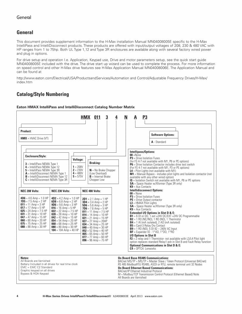
Catalog/Style Numbering
Eaton HMAX IntelliPass and IntelliDisconnect Catalog Number Matrix
HMX 011 3 4 N A P3
Product:Software Options:
HMX = HVAC Drive (VT)A - Standard
Intellipass/Options:00 =NoneP3 = Drive Isolation Fuses(for FS 4-7 not available with M1, P6 or PE options)P6 = Drive Isolation Contactor includes drive test switch(For FS 4-7 not available with M1, P3 or PE options)L4 = Pilot Lights (not available with M1)M1 = Manual Bypass - includes pilot lights and Isolation contactor (not available with any other wired option)IS = Isolation Switch not available with M1, P6 or PE optionsSA = Space Heater w/Xformer (Type 3R only)K9 = Aux ContactsIntellidisconnect Options:00 = NoneP3 = Drive Isolation FusesPE = Drive Output contactorL3 = HMAX Pilot LightsSA = Space Heater w/Xformer (Type 3R only)K9 = Aux ContactsExtended I/O Options in Slot D & E:B1 = 6 DI or DO, 1 ext +24V DC/EXT +24V DC ProgrammableB2 = 1 RO (NC/NO), 1 RO (NO), 1 ThermistorB4 = 1 AI (mA isolated), 2 AO (mA isolated)B5 = Card-3 Relay Dry ContactB9 = 1 RO (NO), 5 DI 42 – 240V AC InputBF = Expander IO - 1*AO, 1*DO, 1*ROI/O Options in Slot BF2 = 2 relay and 1 Thermistor- not available with L3/L4 Pilot light option replaces standard Relay1 pcb in Slot B and Fault Relay functionOptional Communications in Slot D & E:C4 = OPTC4: Lonworks
Enclosure/Style:Voltage:
3 = IntelliPass NEMA Type 14 = IntelliPass NEMA Type 125 = IntelliPass NEMA Type 3RA = IntelliDisconnect NEMA Type 1B = IntelliDisconnect NEMA Type 12C = IntelliDisconnect NEMA Type 3R
Braking:1 = 208V2 = 230V4 = 480V5 = 575V
N = No Brake Chopper (Low Overload)B = Internal Brake Chopper Low
NEC 208 Volts: NEC 230 Volts: NEC 480 Volts:
4D6 = 4.6 Amp = 1.0 HP7D5 = 7.5 Amp = 2 HP011 = 11 Amp = 3 HP017 = 17 Amp = 5 HP025 = 24 Amp = 7.5 HP031 = 31 Amp = 10 HP047 = 47 Amp = 15 HP060 = 60 Amp = 20 HP075 = 75 Amp = 25 HP088 = 88 Amp = 30 HP
4D2 = 4.2 Amp = 1.0 HP6D8 = 6.8 Amp = 2 HP9D6 = 9.6 Amp = 3 HP016 = 16 Amp = 5 HP022 = 22 Amp = 7.5 HP028 = 28 Amp = 10 HP042 = 42 Amp = 15 HP054 = 54 Amp = 20 HP068 = 68 Amp = 25 HP080 = 80 Amp = 30 HP104 = 104 Amp = 40 HP
2D1 = 2.1 Amp = 1 HP3D4 = 3.4 Amp = 2 HP5D6 = 5.6 Amp = 3 HP7D6 = 7.6 Amp = 5 HP011 = 11 Amp = 7.5 HP014 = 14 Amp = 10 HP021 = 21 Amp = 15 HP027 = 27 Amp = 20HP034 = 34 Amp = 25 HP040 = 40 Amp = 30 HP052 = 52 Amp = 40 HP065 = 65 Amp = 50 HP077 = 77 Amp = 60 HP096 = 96 Amp = 75 HP
Notes:All Boards are VarnishedBattery Included in all drives for real time clockEMC = EMC C2 StandardGraphic keypad on all drivesBypass & HOA Keypad
On Board Base RS485 Communications:BACnet MS/TP = MS/TP = Master Slave / Token Protocol (Universal BACnet)RS 485 ModbusRTU RS485, ASCII or RTU, remote terminal unit 32 NodesOn Board Ethernet Based Communications:BACnet/IP Ethernet Industrial ProtocolM = Modbus/TCP Transmission Control Protocol (Ethernet Based) NoteAll Boards are Varnished
4
General
H-Max Series Drives IntelliPass®/IntelliDisconnect® IL04008003E April 2013 www.eaton.com
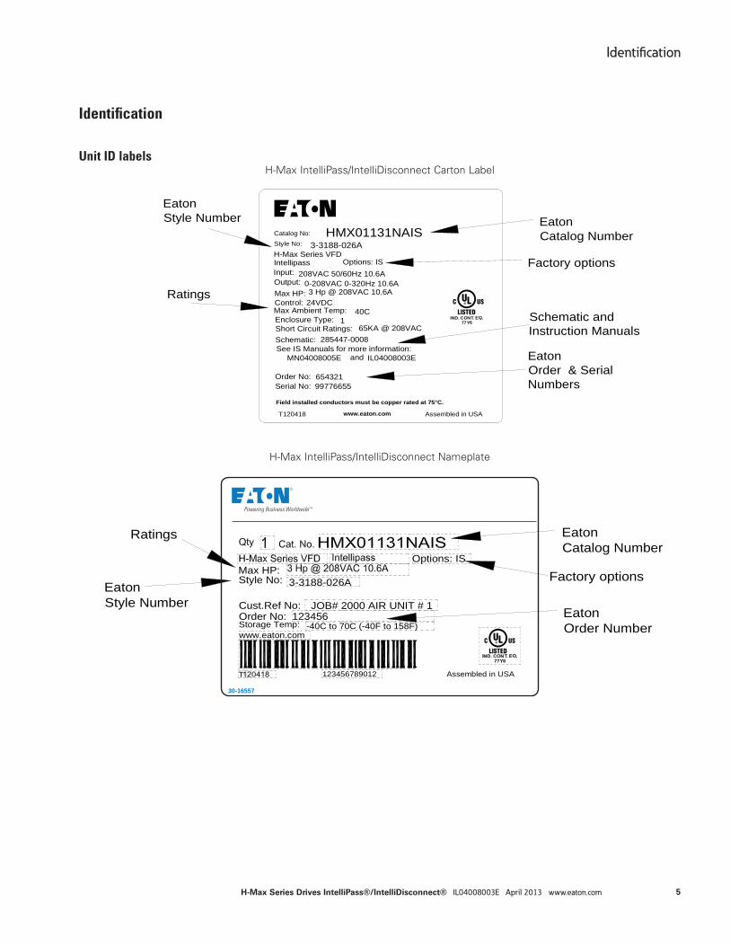
Identifi cation
Unit ID labelsH-Max IntelliPass/IntelliDisconnect Carton Label
H-Max IntelliPass/IntelliDisconnect Nameplate
IND. CONT. EQ.77Y6
www.eaton.com
Enclosure Type:Short Circuit Ratings:
See IS Manuals for more information:
99776655
Schematic:
T
HMX01131NAISCatalog No:
Max Ambient Temp:
Order No:
1
Intellipass
Field installed conductors must be copper rated at 75°C.
Input:Output:Max HP:
0-208VAC 0-320Hz 10.6A208VAC 50/60Hz 10.6A
IL04008003E
3 Hp @ 208VAC 10.6AControl: 24VDC
40C
H-Max Series VFDStyle No: 3-3188-026A
285447-0008
MN04008005E and
65KA @ 208VAC
654321
Assembled in USA
Serial No:
120418
Options: IS
EatonCatalog Number
Factory options
EatonOrder & SerialNumbers
EatonStyle Number
Ratings
Schematic andInstruction Manuals
EatonCatalog Number
Factory options
EatonOrder Number
EatonStyle Number
Ratings
Assembled in USA123456789012
123456-40C to 70C (-40F to 158F)
3-3188-026AStyle No:
Storage Temp:
Max HP:
Order No:JOB# 2000 AIR UNIT # 1Cust.Ref No:
www.eaton.com
Options: IS
30-16557
5
Identifi cation
H-Max Series Drives IntelliPass®/IntelliDisconnect® IL04008003E April 2013 www.eaton.com
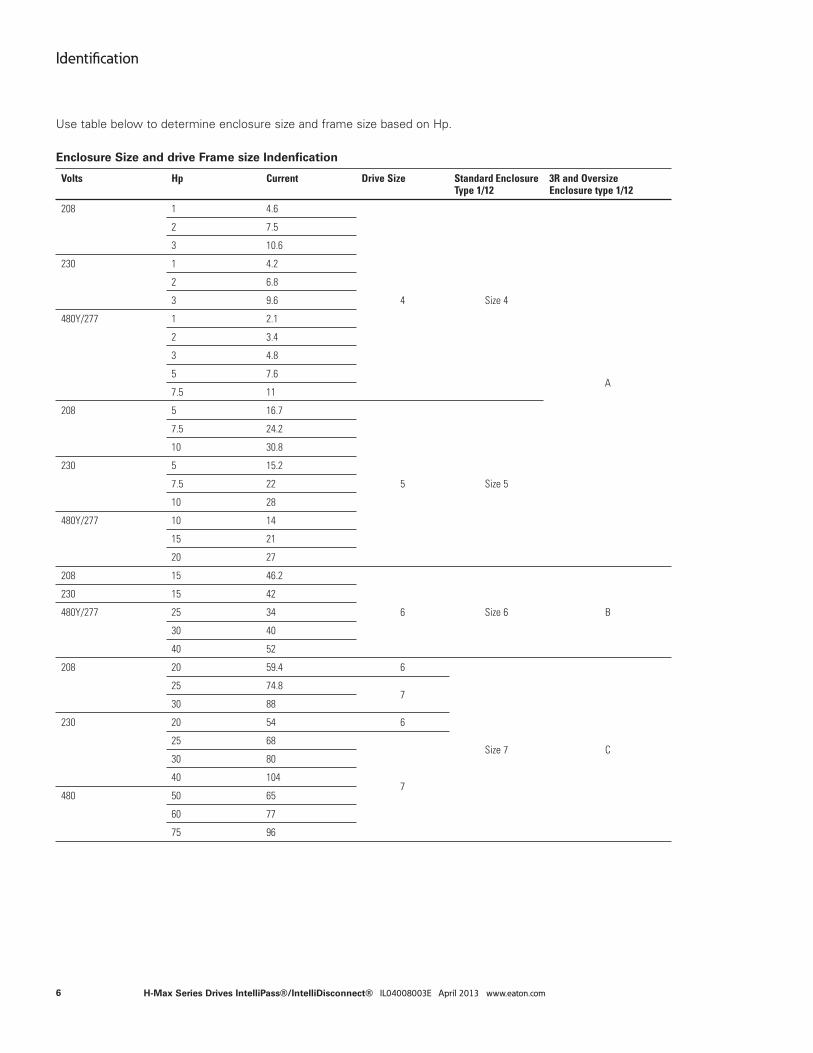
Use table below to determine enclosure size and frame size based on Hp.
Enclosure Size and drive Frame size Indenfication
Volts Hp Current Drive Size Standard Enclosure Type 1/12
3R and OversizeEnclosure type 1/12
208 1 4.6
4 Size 4
A
2 7.5
3 10.6
230 1 4.2
2 6.8
3 9.6
480Y/277 1 2.1
2 3.4
3 4.8
5 7.6
7.5 11
208 5 16.7
5 Size 5
7.5 24.2
10 30.8
230 5 15.2
7.5 22
10 28
480Y/277 10 14
15 21
20 27
208 15 46.2
6 Size 6 B
230 15 42
480Y/277 25 34
30 40
40 52
208 20 59.4 6
Size 7 C
25 74.87
30 88
230 20 54 6
25 68
7
30 80
40 104
480 50 65
60 77
75 96
6
Identifi cation
H-Max Series Drives IntelliPass®/IntelliDisconnect® IL04008003E April 2013 www.eaton.com
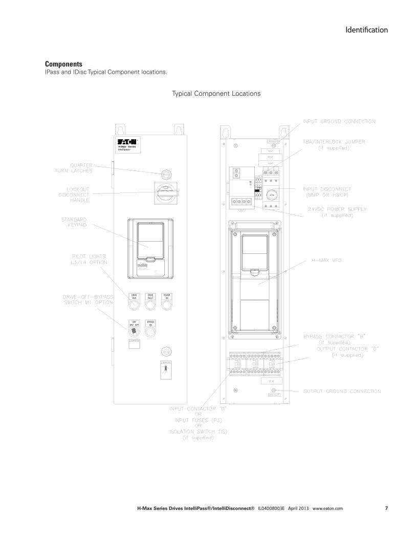
ComponentsIPass and IDisc Typical Component locations.
Typical Component Locations
H-MaxTM Series
®
Intellipass ®
Active Energy Control
An Eaton Green Solution
2 3
32
4
4
7
Identifi cation
H-Max Series Drives IntelliPass®/IntelliDisconnect® IL04008003E April 2013 www.eaton.com
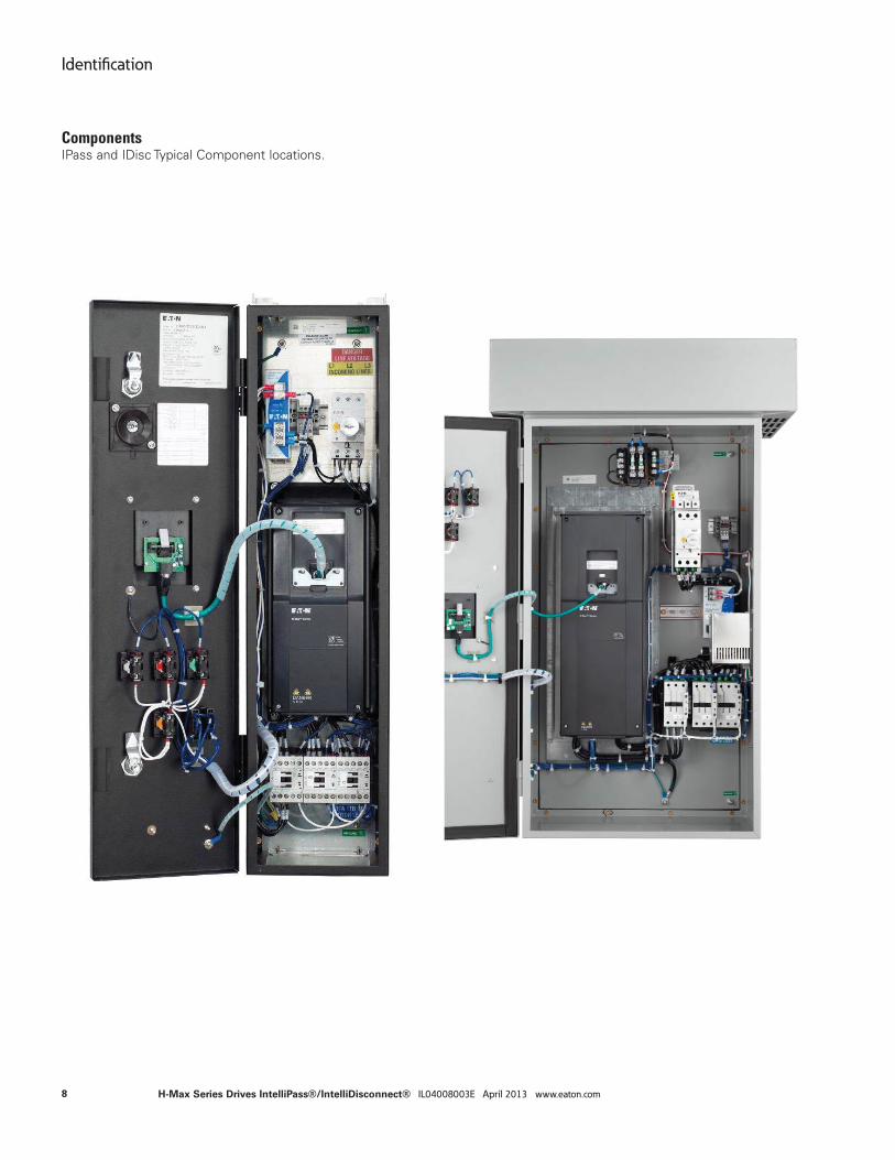
ComponentsIPass and IDisc Typical Component locations.
8
Identifi cation
H-Max Series Drives IntelliPass®/IntelliDisconnect® IL04008003E April 2013 www.eaton.com
Factory Wired Options
The Intellpass and IntelliDisconnect can be supplied with serveral factory wired power options. The sections below describe the options.
Options
HMAX Option Matrix IPass IDisc
P3 - Drive Isolation Fuses X X
P6 - Drive Isolation Contactor includes manual switch X N/A
PE - Drive Output contactor N/A X
IS - Isolation Switch X N/A
SA - Space Heater (3R only) X X
K9 - Aux Contacts X X
M1 - Manual Bypass includes L4 and drive isolation contactor and door switch X N/A
L3 - H-Max Pilot Lights N/A X
L4 - H-Max Pilot Lights X N/A
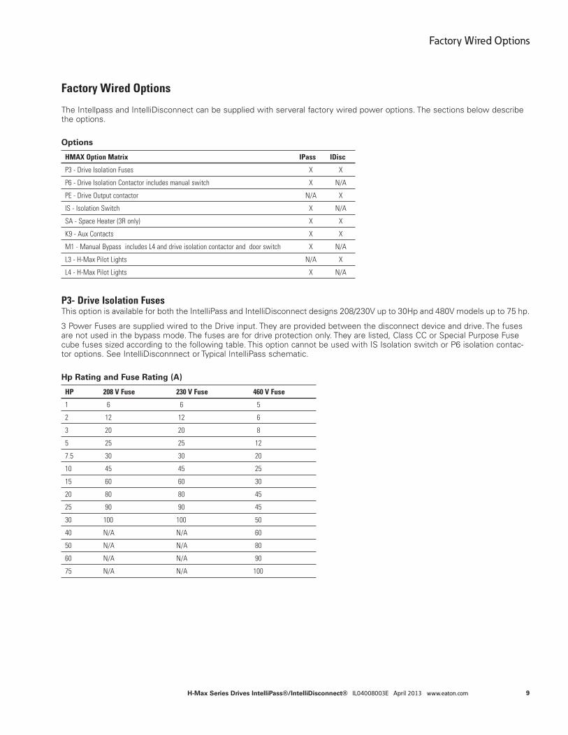
P3- Drive Isolation FusesThis option is available for both the IntelliPass and IntelliDisconnect designs 208/230V up to 30Hp and 480V models up to 75 hp.
3 Power Fuses are supplied wired to the Drive input. They are provided between the disconnect device and drive. The fuses are not used in the bypass mode. The fuses are for drive protection only. They are listed, Class CC or Special Purpose Fuse cube fuses sized according to the following table. This option cannot be used with IS Isolation switch or P6 isolation contac-tor options. See IntelliDisconnnect or Typical IntelliPass schematic.
Hp Rating and Fuse Rating (A)
HP 208 V Fuse 230 V Fuse 460 V Fuse
1 6 6 5
2 12 12 6
3 20 20 8
5 25 25 12
7.5 30 30 20
10 45 45 25
15 60 60 30
20 80 80 45
25 90 90 45
30 100 100 50
40 N/A N/A 60
50 N/A N/A 80
60 N/A N/A 90
75 N/A N/A 100
9
Factory Wired Options
H-Max Series Drives IntelliPass®/IntelliDisconnect® IL04008003E April 2013 www.eaton.com
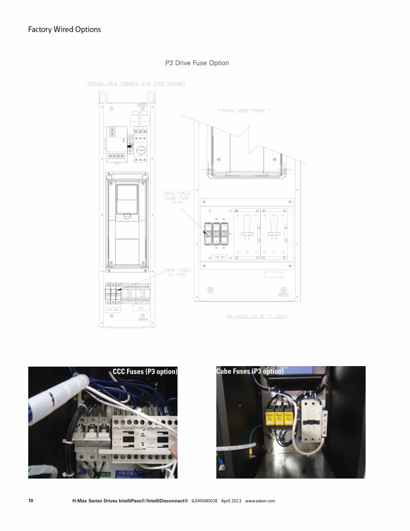
CCC Fuses (P3 option) Cube Fuses (P3 option)
P3 Drive Fuse Option
10
Factory Wired Options
H-Max Series Drives IntelliPass®/IntelliDisconnect® IL04008003E April 2013 www.eaton.com
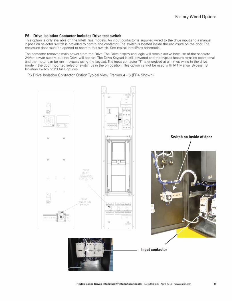
P6 – Drive Isolation Contactor includes Drive test switchThis option is only available on the IntelliPass models. An input contactor is supplied wired to the drive input and a manual 2 position selector switch is provided to control the contactor. The switch is located inside the enclosure on the door. The enclosure door must be opened to operate this switch. See typical IntelliPass schematic.
The contactor removes main power from the Drive. The Drive display and logic will remain active because of the separate 24Volt power supply, but the Drive will not run. The Drive Keypad is still powered and the bypass feature remains operational and the motor can be run in bypass using the keypad. The input contactor “I” is energized at all times while in the drive mode if the door mounted selector switch us in the on position. This option cannot be used with M1 Manual Bypass, IS Isolation switch or P3 fuse options.
P6 Drive Isolation Contactor Option Typical View Frames 4 - 6 (FR4 Shown)
Switch on inside of door
Input contactor
2 3
32
4
4
11
Factory Wired Options
H-Max Series Drives IntelliPass®/IntelliDisconnect® IL04008003E April 2013 www.eaton.com
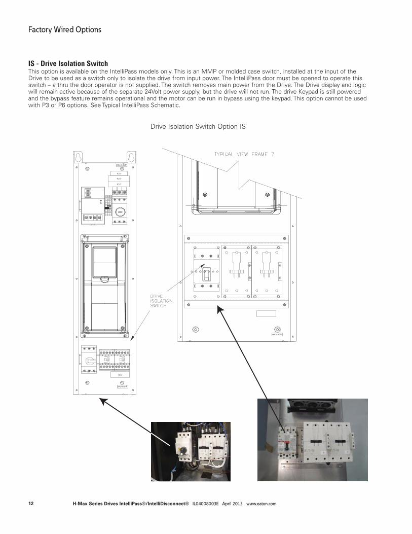
IS - Drive Isolation SwitchThis option is available on the IntelliPass models only. This is an MMP or molded case switch, installed at the input of the Drive to be used as a switch only to isolate the drive from input power. The IntelliPass door must be opened to operate this switch – a thru the door operator is not supplied. The switch removes main power from the Drive. The Drive display and logic will remain active because of the separate 24Volt power supply, but the drive will not run. The drive Keypad is still powered and the bypass feature remains operational and the motor can be run in bypass using the keypad. This option cannot be used with P3 or P6 options. See Typical IntelliPass Schematic.
Drive Isolation Switch Option IS
2 3
32
4
4
12
Factory Wired Options
H-Max Series Drives IntelliPass®/IntelliDisconnect® IL04008003E April 2013 www.eaton.com

M1 - Manual Bypass (forced) SwitchThis option is available on the IntelliPass models only. This option includes an input contactor “I”, L4 pilot light option and a 3 position door mounted selector switch - marked Drives/Off/Bypass. This switch manually overrides the Bypass control from the system (keypad) and puts unit in bypass or in an OFF mode. See IntelliPass Schematic with M1 option.
When the door switch is in the Drive position, the H-Max Drive logic controls the motor and the keypad selects the operation (Drive or Bypass), the control source and place (HOA, KEYPAD or Terminal block). The input contactor “I” is energized at all times while in the drive mode.
When the door switch is moved to Bypass, three actions occur: 1) Drive input isolation contactor is forced open, 2) Drive output contactor will be forced open and the bypass contactor will be forced closed. The motor will immediately start and run full speed across the line regardless of the state of the system or drive.3) The Drive will be forced to the bypass mode and the Keypad Display will show “Bypass”. When the switch is moved back the Drive position, Drive operation is restored and the system may need to be restarted.
When the switch is in the off position neither the drive or bypass operation is possible. Moving the Switch to the off or bypass position while the Drive is operating may cause the Drive to fault because the input power to the drive is removed by the input contactor. See L4 for description/operation of the door mounted pilot lights.
Manual Bypass Option M1
H-MaxTM Series
®
Intellipass ®
Active Energy Control
An Eaton Green Solution
2 3
32
4
4
M1 Option
3R Versions have Bypassswitch located in Keypad Enclosure
13
Factory Wired Options
H-Max Series Drives IntelliPass®/IntelliDisconnect® IL04008003E April 2013 www.eaton.com
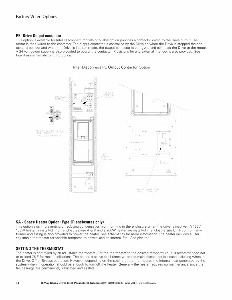
PE- Drive Output contactorThis option is available for IntelliDisconnect models only. This option provides a contactor wired to the Drive output. The motor is then wired to the contactor. The output contactor is controlled by the Drive so when the Drive is stopped the con-tactor drops out and when the Drive is in a run mode, the output contactor is energized and connects the Drive to the motor. A 24 volt power supply is also provided to power the contactor. Provisions for and external interlock is also provided. See IntelliPass schematic with PE option.
IntelliDisconnect PE Output Contactor Option
PS
L
N
24V 2.5A
-+
50-60Hz100-240V~ 1.5A
DC OK
Adjust
SA - Space Heater Option (Type 3R enclosures only)This option aids in preventing or reducing condensation from forming in the enclosure when the drive is inactive. A 120V 100W heater is installed in 3R enclosures size A & B and a 200W heater are installed in enclosure size C. A control trans-former and fusing is also provided to power the heater. See schematics for more information. The heater includes a user adjustable thermostat for variable temperature control and an internal fan. See pictures
SETTING THE THERMOSTATThe heater is controlled by an adjustable thermostat. Set the thermostat to the desired temperature. It is recommended not to exceed 75 F for most applications. The heater is active at all times when the main disconnect is closed including when in the Drive, Off or Bypass operation. However, depending on the setting of the thermostat, the internal heat generated by the system when in operation should be enough to turn off the heater. Generally the heater requires no maintenance since the fan bearings are permanently lubricated and sealed.
14
Factory Wired Options
H-Max Series Drives IntelliPass®/IntelliDisconnect® IL04008003E April 2013 www.eaton.com
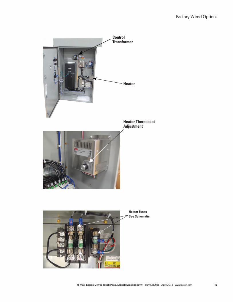
Heater
ControlTransformer
Heater Thermostat Adjustment
Heater FusesSee Schematic
15
Factory Wired Options
H-Max Series Drives IntelliPass®/IntelliDisconnect® IL04008003E April 2013 www.eaton.com
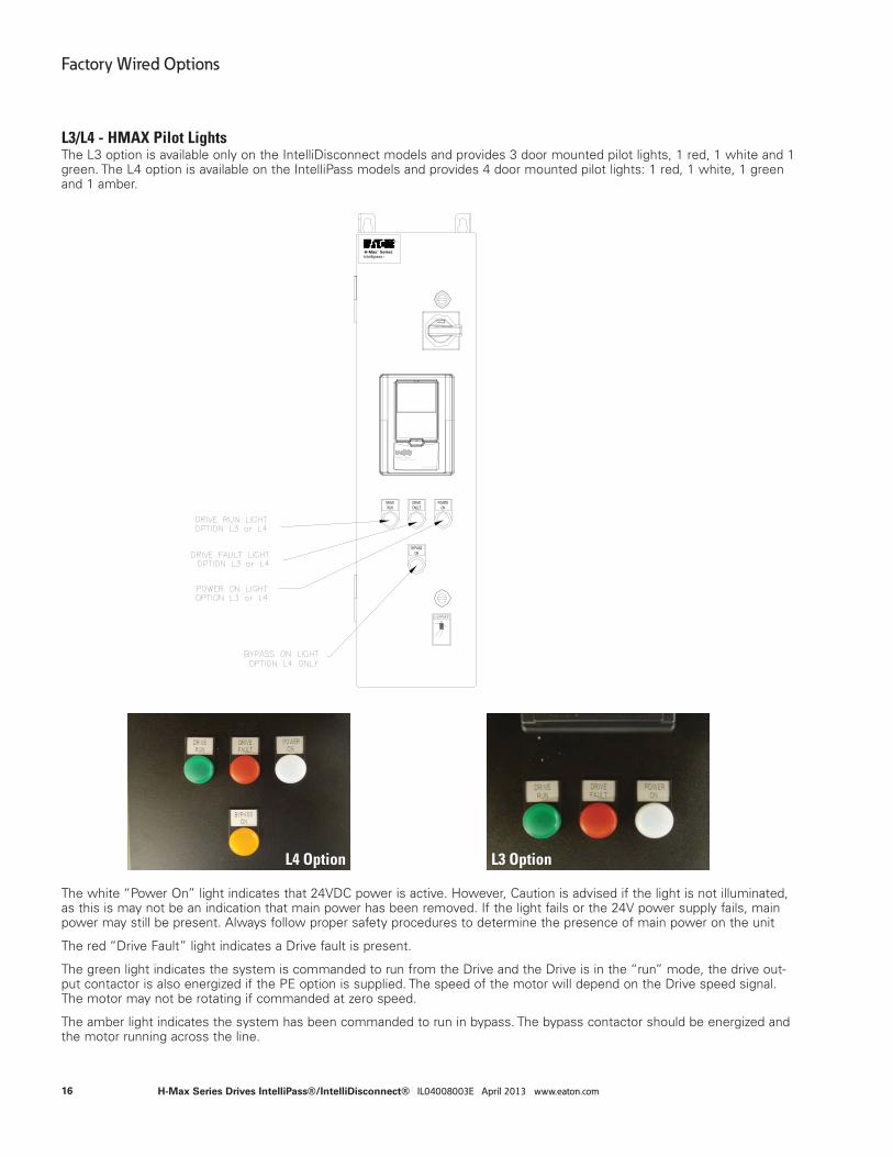
L3/L4 - HMAX Pilot LightsThe L3 option is available only on the IntelliDisconnect models and provides 3 door mounted pilot lights, 1 red, 1 white and 1 green. The L4 option is available on the IntelliPass models and provides 4 door mounted pilot lights: 1 red, 1 white, 1 green and 1 amber.
H-MaxTM Series
®
Intellipass ®
Active Energy Control
An Eaton Green Solution
L4 Option L3 Option
The white “Power On” light indicates that 24VDC power is active. However, Caution is advised if the light is not illuminated, as this is may not be an indication that main power has been removed. If the light fails or the 24V power supply fails, main power may still be present. Always follow proper safety procedures to determine the presence of main power on the unit
The red “Drive Fault” light indicates a Drive fault is present.
The green light indicates the system is commanded to run from the Drive and the Drive is in the “run” mode, the drive out-put contactor is also energized if the PE option is supplied. The speed of the motor will depend on the Drive speed signal. The motor may not be rotating if commanded at zero speed.
The amber light indicates the system has been commanded to run in bypass. The bypass contactor should be energized and the motor running across the line.
16
Factory Wired Options
H-Max Series Drives IntelliPass®/IntelliDisconnect® IL04008003E April 2013 www.eaton.com
Plug in options
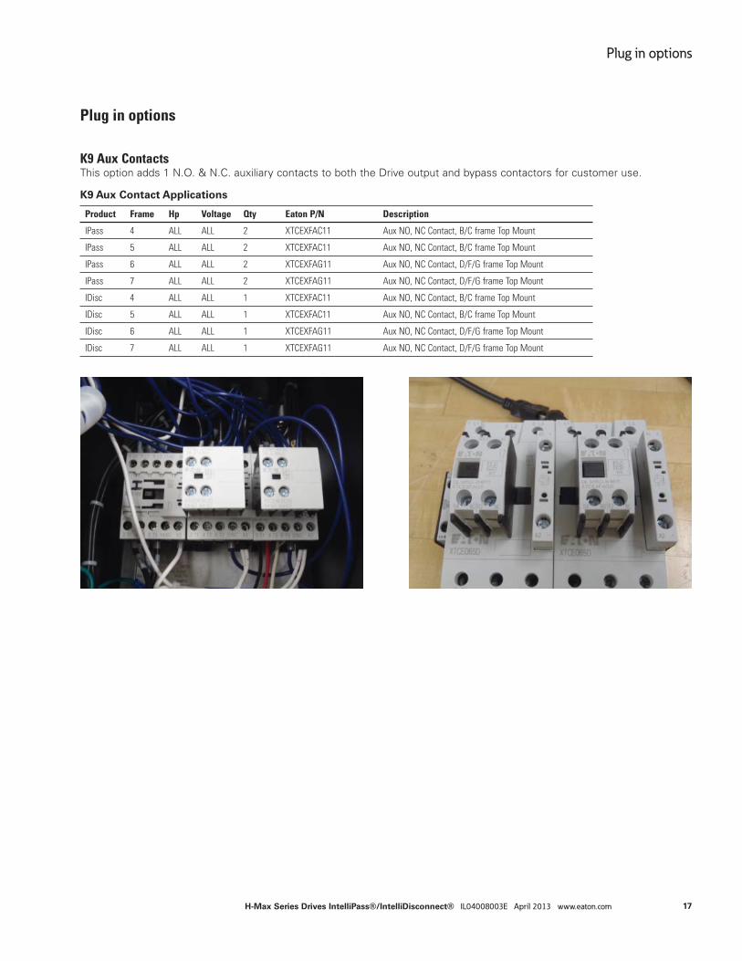
K9 Aux ContactsThis option adds 1 N.O. & N.C. auxiliary contacts to both the Drive output and bypass contactors for customer use.
K9 Aux Contact Applications
Product Frame Hp Voltage Qty Eaton P/N Description
IPass 4 ALL ALL 2 XTCEXFAC11 Aux NO, NC Contact, B/C frame Top Mount
IPass 5 ALL ALL 2 XTCEXFAC11 Aux NO, NC Contact, B/C frame Top Mount
IPass 6 ALL ALL 2 XTCEXFAG11 Aux NO, NC Contact, D/F/G frame Top Mount
IPass 7 ALL ALL 2 XTCEXFAG11 Aux NO, NC Contact, D/F/G frame Top Mount
IDisc 4 ALL ALL 1 XTCEXFAC11 Aux NO, NC Contact, B/C frame Top Mount
IDisc 5 ALL ALL 1 XTCEXFAC11 Aux NO, NC Contact, B/C frame Top Mount
IDisc 6 ALL ALL 1 XTCEXFAG11 Aux NO, NC Contact, D/F/G frame Top Mount
IDisc 7 ALL ALL 1 XTCEXFAG11 Aux NO, NC Contact, D/F/G frame Top Mount
17
Plug in options
H-Max Series Drives IntelliPass®/IntelliDisconnect® IL04008003E April 2013 www.eaton.com
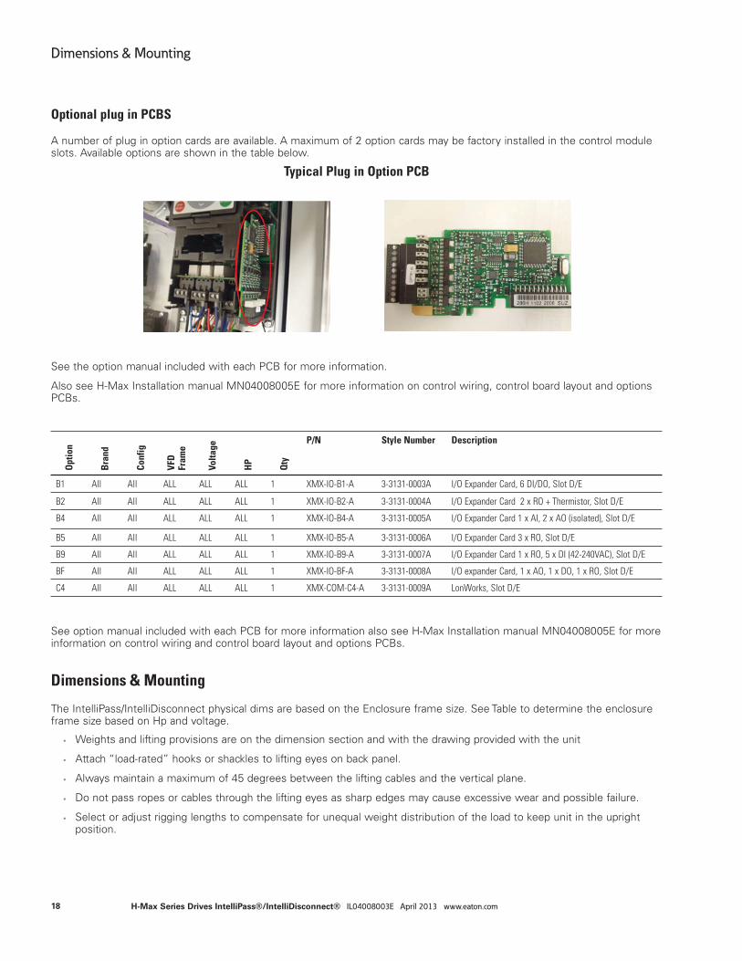
Optional plug in PCBS
A number of plug in option cards are available. A maximum of 2 option cards may be factory installed in the control module slots. Available options are shown in the table below.
Typical Plug in Option PCB
See the option manual included with each PCB for more information.
Also see H-Max Installation manual MN04008005E for more information on control wiring, control board layout and options PCBs.
See option manual included with each PCB for more information also see H-Max Installation manual MN04008005E for more information on control wiring and control board layout and options PCBs.
Dimensions & Mounting
The IntelliPass/IntelliDisconnect physical dims are based on the Enclosure frame size. See Table to determine the enclosure frame size based on Hp and voltage.
• Weights and lifting provisions are on the dimension section and with the drawing provided with the unit
• Attach “load-rated” hooks or shackles to lifting eyes on back panel.
• Always maintain a maximum of 45 degrees between the lifting cables and the vertical plane.
• Do not pass ropes or cables through the lifting eyes as sharp edges may cause excessive wear and possible failure.
• Select or adjust rigging lengths to compensate for unequal weight distribution of the load to keep unit in the upright position.
Opt
ion
Bra
nd
Conf
ig
VFD
Fr
ame
Volta
ge
HP
Qty
P/N Style Number Description
B1 All All ALL ALL ALL 1 XMX-IO-B1-A 3-3131-0003A I/O Expander Card, 6 DI/DO, Slot D/E
B2 All All ALL ALL ALL 1 XMX-IO-B2-A 3-3131-0004A I/O Expander Card 2 x RO + Thermistor, Slot D/E
B4 All All ALL ALL ALL 1 XMX-IO-B4-A 3-3131-0005A I/O Expander Card 1 x AI, 2 x AO (isolated), Slot D/E
B5 All All ALL ALL ALL 1 XMX-IO-B5-A 3-3131-0006A I/O Expander Card 3 x RO, Slot D/E
B9 All All ALL ALL ALL 1 XMX-IO-B9-A 3-3131-0007A I/O Expander Card 1 x RO, 5 x DI (42-240VAC), Slot D/E
BF All All ALL ALL ALL 1 XMX-IO-BF-A 3-3131-0008A I/O expander Card, 1 x AO, 1 x DO, 1 x RO, Slot D/E
C4 All All ALL ALL ALL 1 XMX-COM-C4-A 3-3131-0009A LonWorks, Slot D/E
18
Dimensions & Mounting
H-Max Series Drives IntelliPass®/IntelliDisconnect® IL04008003E April 2013 www.eaton.com
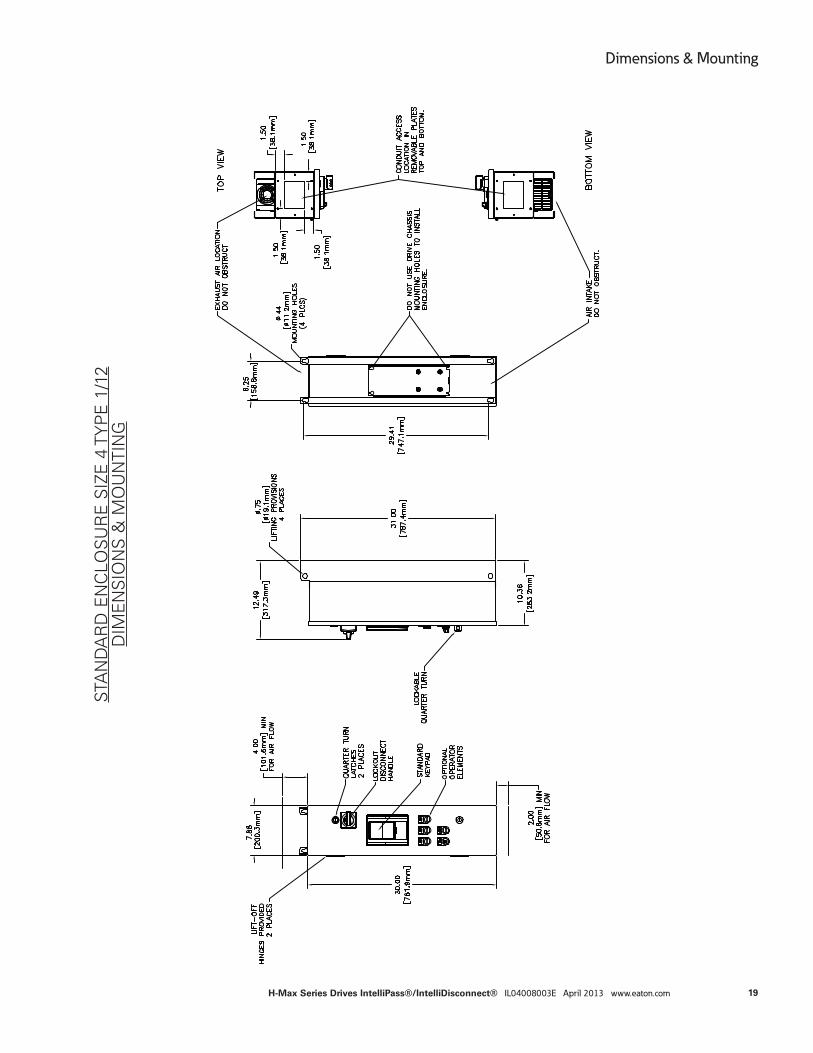
STA
ND
AR
D E
NC
LOS
UR
E S
IZE
4 T
YP
E 1
/12
DIM
EN
SIO
NS
& M
OU
NTI
NG
19
Dimensions & Mounting
H-Max Series Drives IntelliPass®/IntelliDisconnect® IL04008003E April 2013 www.eaton.com
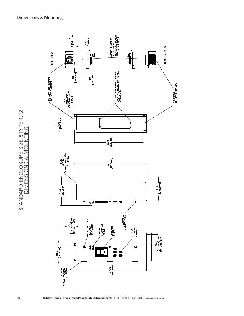
STA
ND
AR
D E
NC
LOS
UR
E S
IZE
5 T
YP
E 1
/12
DIM
EN
SIO
NS
& M
OU
NTI
NG
20
Dimensions & Mounting
H-Max Series Drives IntelliPass®/IntelliDisconnect® IL04008003E April 2013 www.eaton.com
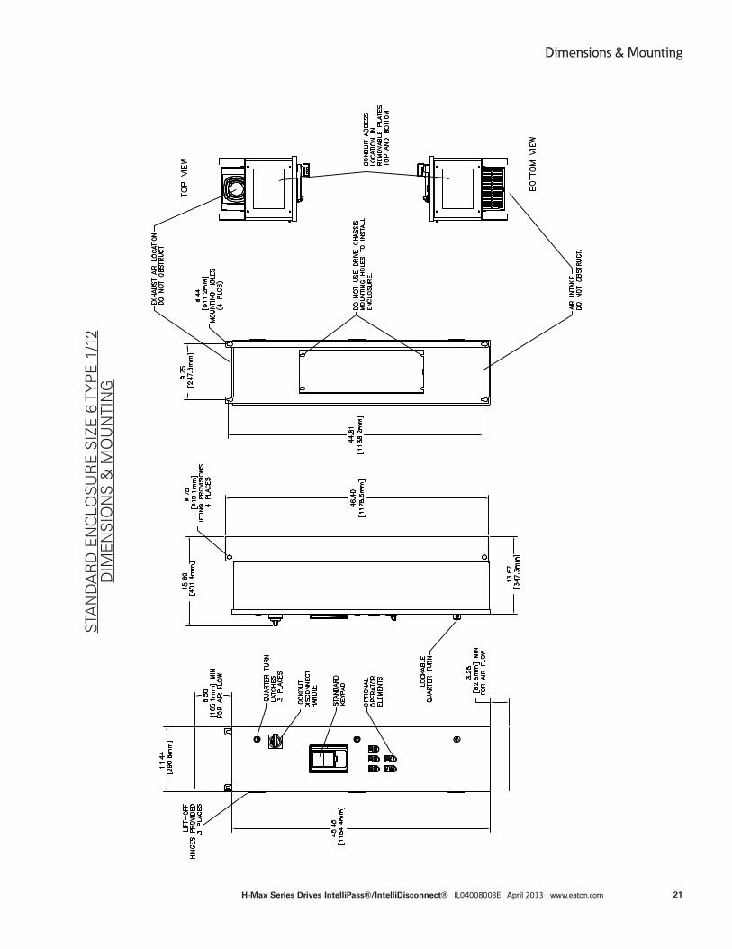
STA
ND
AR
D E
NC
LOS
UR
E S
IZE
6 T
YP
E 1
/12
DIM
EN
SIO
NS
& M
OU
NTI
NG
21
Dimensions & Mounting
H-Max Series Drives IntelliPass®/IntelliDisconnect® IL04008003E April 2013 www.eaton.com
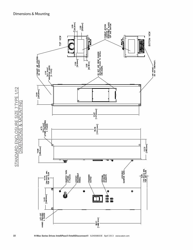
STA
ND
AR
D E
NC
LOS
UR
E S
IZE
7 T
YP
E 1
/12
DIM
EN
SIO
NS
& M
OU
NTI
NG
22
Dimensions & Mounting
H-Max Series Drives IntelliPass®/IntelliDisconnect® IL04008003E April 2013 www.eaton.com
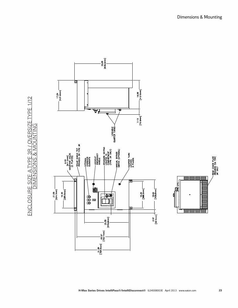
EN
CLO
SU
RE
SIZ
E A
TY
PE
3R
/ O
VE
RS
IZE
TY
PE
1/1
2D
IME
NS
ION
S &
MO
UN
TIN
G
23
Dimensions & Mounting
H-Max Series Drives IntelliPass®/IntelliDisconnect® IL04008003E April 2013 www.eaton.com
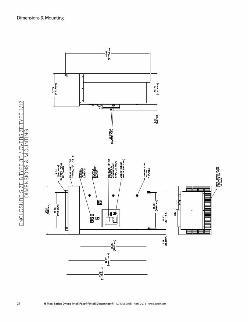
EN
CLO
SU
RE
SIZ
E B
TY
PE
3R
/ O
VE
RS
IZE
TY
PE
1/1
2D
IME
NS
ION
S &
MO
UN
TIN
G
24
Dimensions & Mounting
H-Max Series Drives IntelliPass®/IntelliDisconnect® IL04008003E April 2013 www.eaton.com
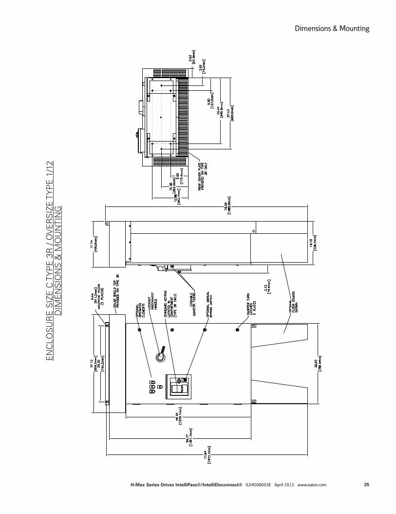
EN
CLO
SU
RE
SIZ
E C
TY
PE
3R
/ O
VE
RS
IZE
TY
PE
1/1
2D
IME
NS
ION
S &
MO
UN
TIN
G
25
Dimensions & Mounting
H-Max Series Drives IntelliPass®/IntelliDisconnect® IL04008003E April 2013 www.eaton.com
Wiring
Schematic A schematic is included with each product. The schematic number can be found on the product nameplate.
Typical schematics are shown on the next few pages.
NOTE:
Power and Motor Leads must be in separate conduit.
Do not run control wires in same conduit as input power or motor wires
Two grounding points are provided, input ground and output ground
Ground unit properly – improper grounding could damage the unit
26
Wiring
H-Max Series Drives IntelliPass®/IntelliDisconnect® IL04008003E April 2013 www.eaton.com
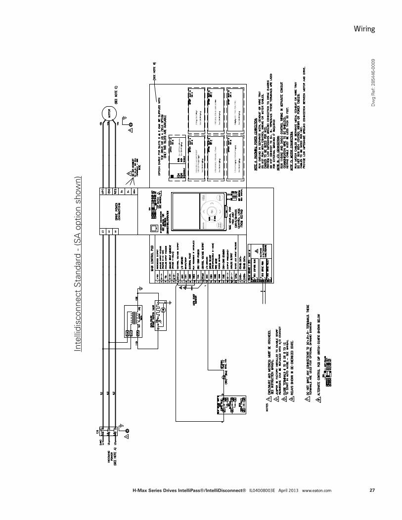
Inte
llidi
scon
nect
Sta
ndar
d - (
SA o
ptio
n sh
own)
Dw
g R
ef: 2
8544
6-00
09
27
Wiring
H-Max Series Drives IntelliPass®/IntelliDisconnect® IL04008003E April 2013 www.eaton.com
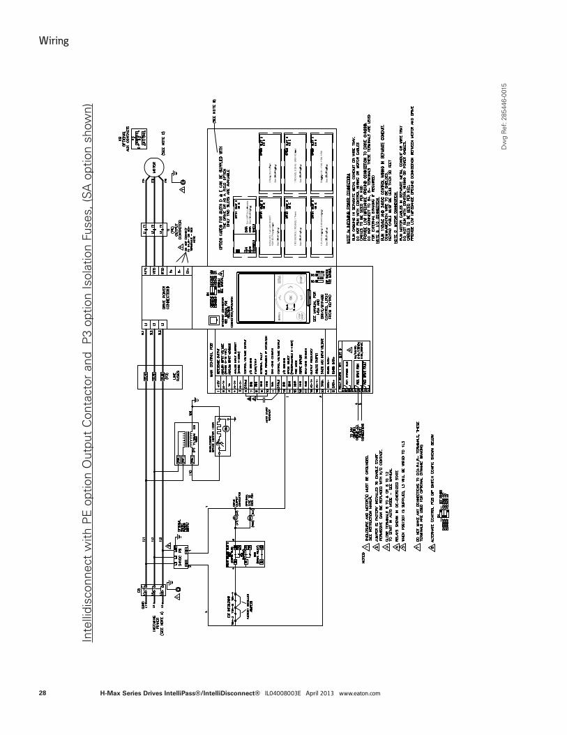
Inte
llidi
scon
nect
with
PE
opt
ion
Out
put
Con
tact
or a
nd
P3
optio
n Is
olat
ion
Fuse
s, (S
A o
ptio
n sh
own)
Dw
g R
ef: 2
8544
6-00
15
28
Wiring
H-Max Series Drives IntelliPass®/IntelliDisconnect® IL04008003E April 2013 www.eaton.com
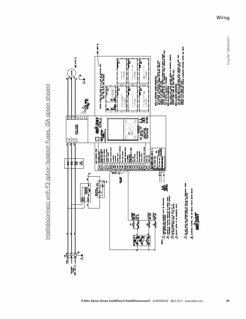
Inte
llidi
scon
nect
with
P3
optio
n Is
olat
ion
Fuse
s, (S
A o
ptio
n sh
own)
Dw
g R
ef: 2
8544
6-00
11
29
Wiring
H-Max Series Drives IntelliPass®/IntelliDisconnect® IL04008003E April 2013 www.eaton.com
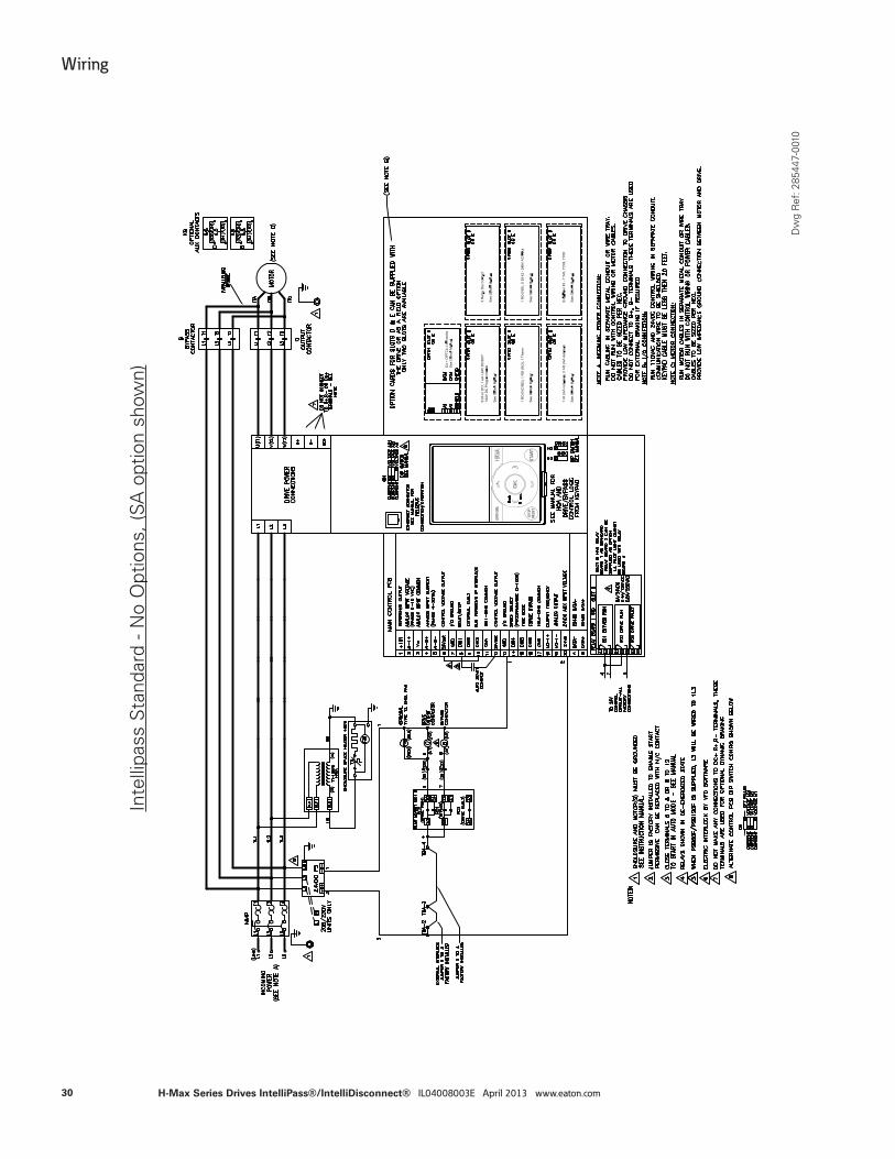
Inte
llipa
ss S
tand
ard
- No
Opt
ions
, (SA
opt
ion
show
n)
Dw
g R
ef: 2
8544
7-00
10
30
Wiring
H-Max Series Drives IntelliPass®/IntelliDisconnect® IL04008003E April 2013 www.eaton.com
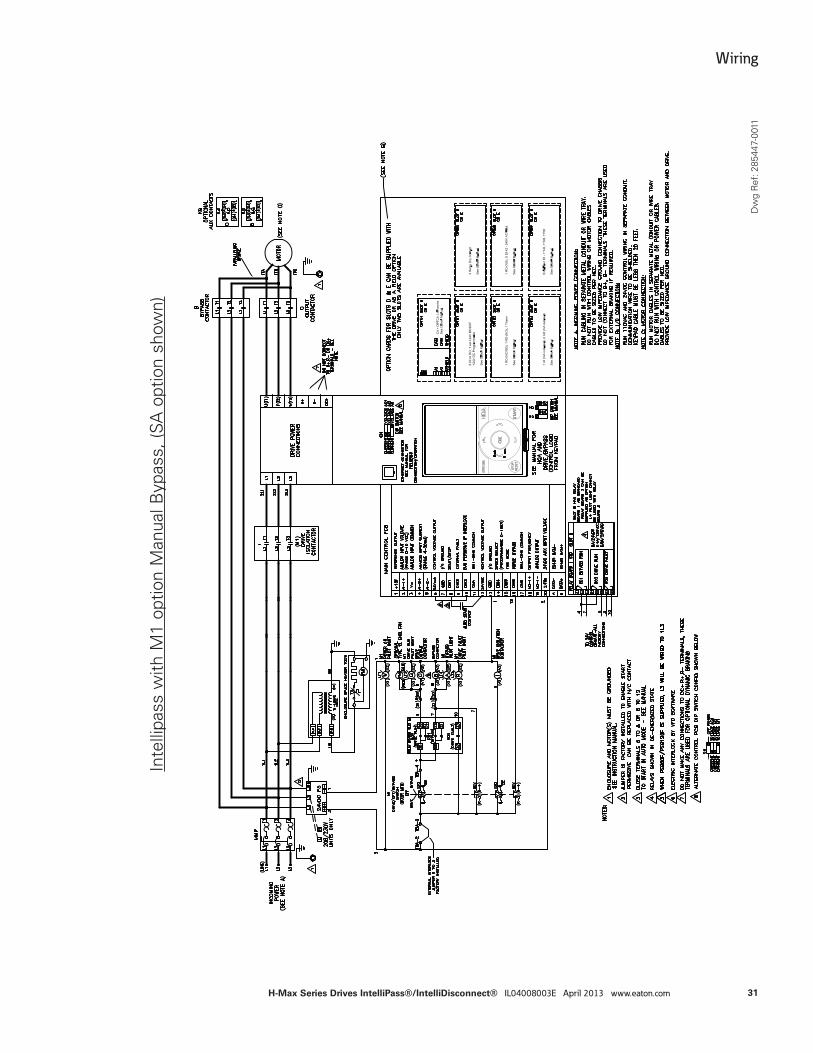
Inte
llipa
ss w
ith M
1 op
tion
Man
ual B
ypas
s, (S
A o
ptio
n sh
own)
Dw
g R
ef: 2
8544
7-00
11
31
Wiring
H-Max Series Drives IntelliPass®/IntelliDisconnect® IL04008003E April 2013 www.eaton.com
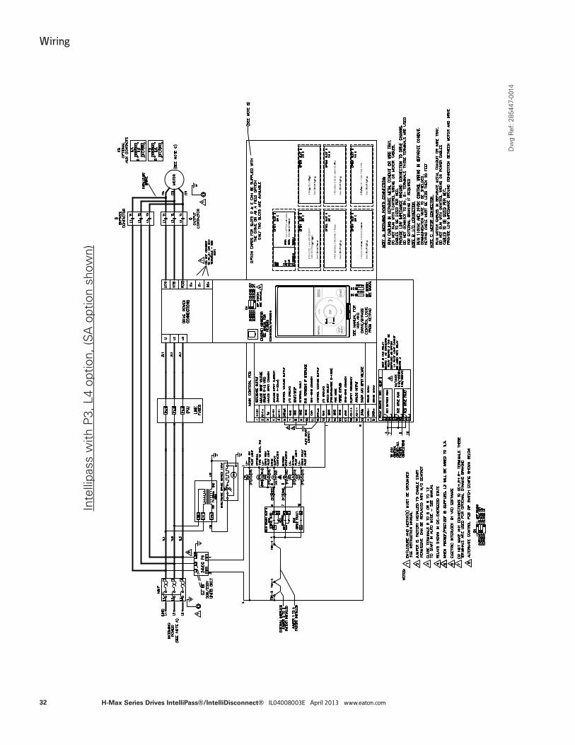
Inte
llipa
ss w
ith P
3, L
4 op
tion,
(SA
opt
ion
show
n)
Dw
g R
ef: 2
8544
7-00
14
32
Wiring
H-Max Series Drives IntelliPass®/IntelliDisconnect® IL04008003E April 2013 www.eaton.com
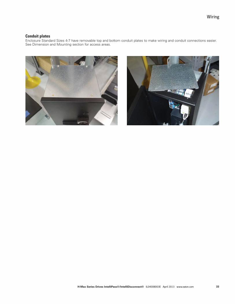
Conduit platesEnclosure Standard Sizes 4-7 have removable top and bottom conduit plates to make wiring and conduit connections easier. See Dimension and Mounting section for access areas.
33
Wiring
H-Max Series Drives IntelliPass®/IntelliDisconnect® IL04008003E April 2013 www.eaton.com
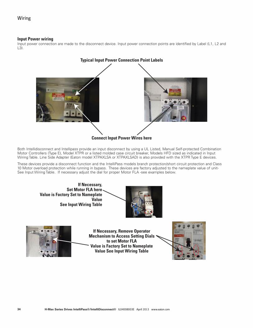
Input Power wiringInput power connection are made to the disconnect device. Input power connection points are identified by Label (L1, L2 and L3).
Typical Input Power Connection Point Labels
Connect Input Power Wires here
Both Intellidisconnect and Intellipass provide an input disconnect by using a UL Listed, Manual Self-protected Combination Motor Controllers (Type E), Model XTPR or a listed molded case circuit breaker, Models HFD sized as indicated in Input Wiring Table. Line Side Adapter (Eaton model XTPAXLSA or XTPAXLSAD) is also provided with the XTPR Type E devices.
These devices provide a disconnect function and the IntelliPass models branch protection/short circuit protection and Class 10 Motor overload protection while running in bypass. These devices are factory adjusted to the nameplate value of unit- See Input Wiring Table. If necessary adjust the dial for proper Motor FLA -see examples below.
If Necessary,Set Motor FLA here
Value is Factory Set to Nameplate Value
See Input Wiring Table
If Necessary, Remove Operator Mechanism to Access Setting Dials
to set Motor FLA Value is Factory Set to Nameplate
Value See Input Wiring Table
34
Wiring
H-Max Series Drives IntelliPass®/IntelliDisconnect® IL04008003E April 2013 www.eaton.com
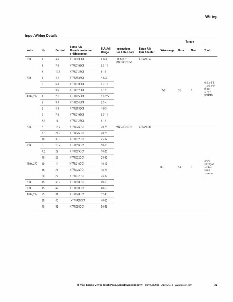
Input Wiring Details
Torque
Volts Hp CurrentEaton P/NBranch protectionor Disconnect
FLA Adj Range
InstructionsSee Eaton.com
Eaton P/NLSA Adapter Wire range lb-in N-m Tool
208 1 4.6 XTPR6P3BC1 4-6.3 PUB51173MN03402005e
XTPAXLSA
14-6 35 4
0.8 x 5.51 x 6 mm (flat) Size 2 pozidriv
2 7.5 XTPR010BC1 6.3-11
3 10.6 XTPR012BC1 8-12
230 1 4.2 XTPR6P3BC1 4-6.3
2 6.8 XTPR010BC1 6.3-11
3 9.6 XTPR012BC1 8-12
480Y/277 1 2.1 XTPR2P5BC1 1.6-2.5
2 3.4 XTPR004BC1 2.5-4
3 4.8 XTPR6P3BC1 4-6.3
5 7.6 XTPR010BC1 6.3-11
7.5 11 XTPR012BC1 8-12
208 5 16.7 XTPR025DC1 20-25 MN03402004e XTPAXLSD
8-0 54 6
4mm Hexagonsocket-headspanner
7.5 24.2 XTPR025DC1 20-25
10 30.8 XTPR032DC1 25-32
230 5 15.2 XTPR016DC1 10-16
7.5 22 XTPR025DC1 16-25
10 28 XTPR032DC1 25-32
480Y/277 10 14 XTPR016DC1 10-16
15 21 XTPR025DC1 16-25
20 27 XTPR032DC1 25-32
208 15 46.2 XTPR050DC1 40-50
230 15 42 XTPR050DC1 40-50
480Y/277 25 34 XTPR040DC1 32-40
30 40 XTPR050DC1 40-50
40 52 XTPR058DC1 50-58
35
Wiring
H-Max Series Drives IntelliPass®/IntelliDisconnect® IL04008003E April 2013 www.eaton.com
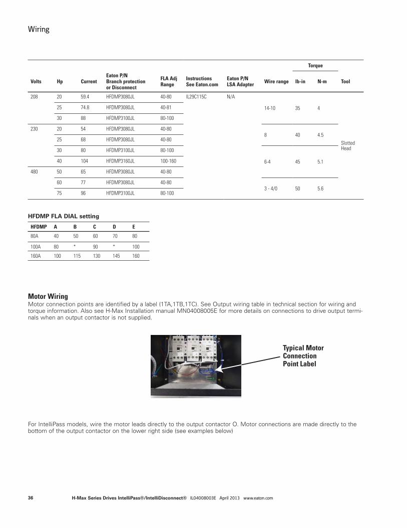
Torque
Volts Hp CurrentEaton P/NBranch protectionor Disconnect
FLA Adj Range
InstructionsSee Eaton.com
Eaton P/NLSA Adapter Wire range lb-in N-m Tool
208 20 59.4 HFDMP3080JL 40-80 IL29C115C N/A
14-10 35 4
Slotted Head
25 74.8 HFDMP3080JL 40-81
30 88 HFDMP3100JL 80-100
230 20 54 HFDMP3080JL 40-808 40 4.5
25 68 HFDMP3080JL 40-80
30 80 HFDMP3100JL 80-100
6-4 45 5.140 104 HFDMP3160JL 100-160
480 50 65 HFDMP3080JL 40-80
60 77 HFDMP3080JL 40-803 - 4/0 50 5.6
75 96 HFDMP3100JL 80-100
HFDMP FLA DIAL setting
HFDMP A B C D E
80A 40 50 60 70 80
100A 80 * 90 * 100
160A 100 115 130 145 160
Motor WiringMotor connection points are identified by a label (1TA,1TB,1TC). See Output wiring table in technical section for wiring and torque information. Also see H-Max Installation manual MN04008005E for more details on connections to drive output termi-nals when an output contactor is not supplied.
For IntelliPass models, wire the motor leads directly to the output contactor O. Motor connections are made directly to the bottom of the output contactor on the lower right side (see examples below)
Typical Motor Connection Point Label
36
Wiring
H-Max Series Drives IntelliPass®/IntelliDisconnect® IL04008003E April 2013 www.eaton.com
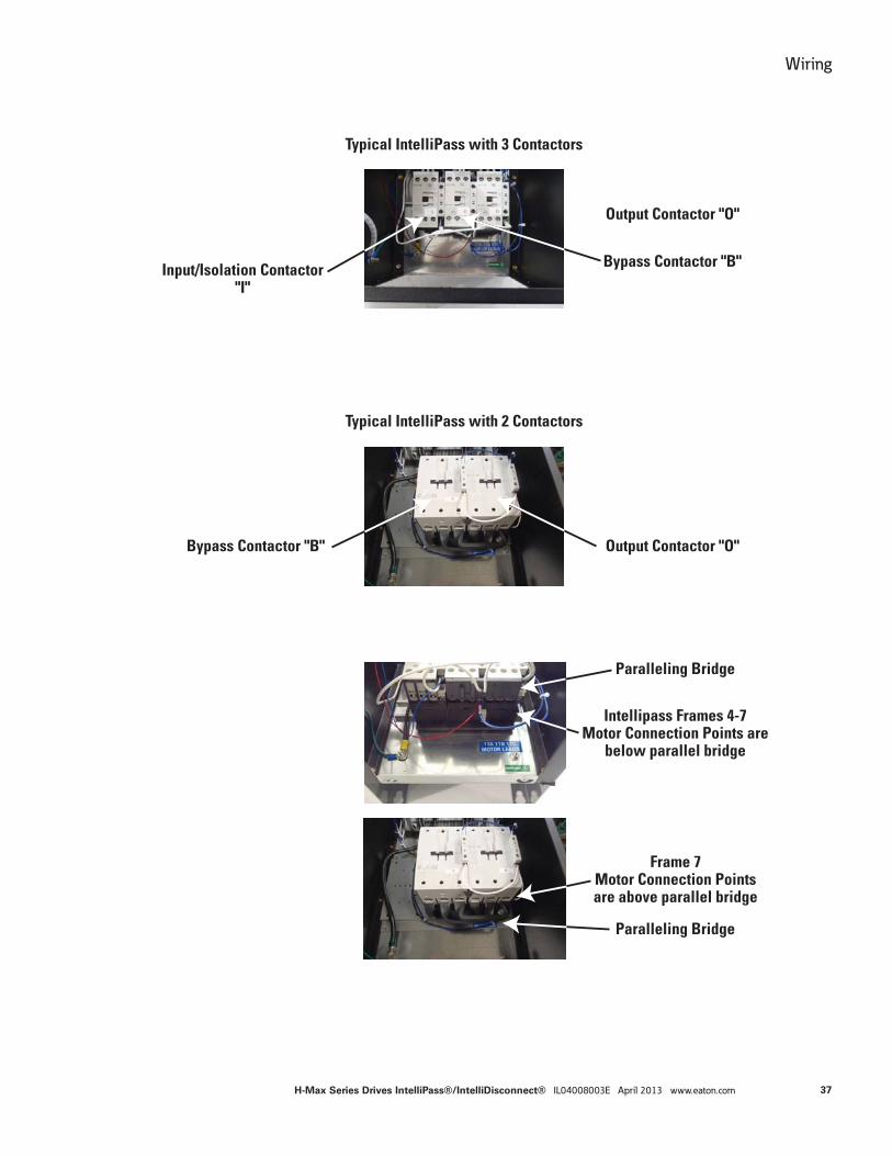
Typical IntelliPass with 3 Contactors
Input/Isolation Contactor"I"
Output Contactor "O"
Bypass Contactor "B"
Output Contactor "O"Bypass Contactor "B"
Typical IntelliPass with 2 Contactors
Paralleling Bridge
Paralleling Bridge
Frame 7Motor Connection Pointsare above parallel bridge
Intellipass Frames 4-7Motor Connection Points are
below parallel bridge
37
Wiring
H-Max Series Drives IntelliPass®/IntelliDisconnect® IL04008003E April 2013 www.eaton.com
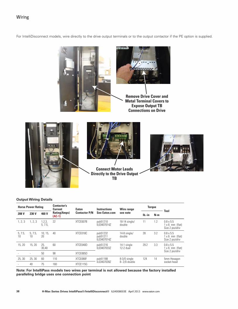
Remove Drive Cover andMetal Terminal Covers to
Expose Output TBConnections on Drive
Connect Motor LeadsDirectly to the Drive Output
TB
For IntelliDisconnect models, wire directly to the drive output terminals or to the output contactor if the PE option is supplied.
Output Wiring Details
Horse Power Rating Contactor’s Current Rating(Amps) {AC-1}
Eaton Contactor P/N
InstructionsSee Eaton.com
Wire rangesee note
TorqueTool
208 V 230 V 460 V lb.-in N-m
1, 2, 3 1, 2, 3 1,2,3, 5, 7.5,
22 XTCE007B pub51210IL03407014Z
18-14 single/double
11 1.2 0.8 x 5.51 x 6 mm (flat) Size 2 pozidriv
5, 7.5, 10
5, 7.5, 10
10, 15, 20
40 XTCE018C pub51232pub51211IL03407014Z
14-8 single/double
28 3.2 0.8 x 5.51 x 6 mm (flat) Size 2 pozidriv
15, 20 15, 20 25, 30,40
60 XTCE040D pub51216IL03407033Z
14-1 single12-2 dual
29.2 3.3 0.8 x 5.51 x 6 mm (flat) Size 2 pozidriv
- - 50 98 XTCE065D
25, 30 25, 30 60 110 XTCE080F pub51188IL03407039Z
8-3/0 single8- 2/0 double
124 14 5mm Hexagon socket-head
- 40 75 160 XTCE115G
Note: For IntelliPass models two wires per terminal is not allowed because the factory installed paralleling bridge uses one connection point
38
Wiring
H-Max Series Drives IntelliPass®/IntelliDisconnect® IL04008003E April 2013 www.eaton.com

Ground WiringBoth input and output ground studs are provided and marked with label. Hardware is also supplied.
Frames 4 thru 6 have 10-32 studs on the back panel, and the supplied nut, flat washer and lock washer should be torqued to 30 lb-in
Frame 7 has 1/4-20 studs on the back panel, and the supplied nut, flat washer and lock washer should be torqued to 65 lb-in
Control WiringNo additional control wiring is necessary for basic operation - see schematic for Auto Start contact, Auto reference connec-tions and interlock connections to control PCB terminal block if required.
See H-Max Installation manual MN04008005E for more information on control wiring and control board layout and connec-tions.
For ease of access the control terminals blocks can be unplugged for wiring.
All control I/O wiring must be segregated from line (mains) and motor cabling.
Run 120 Vac and +24 Vdc control I/O in separate conduit if applicable.
Control I/O terminals must be tightened to 4.5 lb (0.5 Nm).
In addition, the IntelliPass models provide an additional “External Interlock” input on TBA 2 & 3. This can be used to remove the 24V power from the contactors and door control elements. If is factory jumpered. If removed, it removes 24V power to the bypass and drive contactors. It does not disable the drive from running, only from being connected to a motor. Under some circumstances the drive/bypass could still be commanded to run but since the contactors are disabled, the motor will not run, however the drive keypad may indicate it is running. Refer to the schematic
This external interlock input is not supplied on the IntelliDisconnect models unless the output contactor with power supply option is supplied. Refer to the schematic.
Typical Ground Stud and Labels
Typical TBA Interlock
Interlock jumper from 2-3installed at factory
Input Output
39
Wiring
H-Max Series Drives IntelliPass®/IntelliDisconnect® IL04008003E April 2013 www.eaton.com
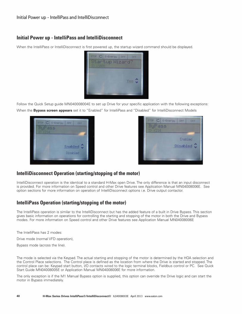
Initial Power up - IntelliPass and IntelliDisconnect
When the IntelliPass or IntelliDisconnect is first powered up, the startup wizard command should be displayed.
Follow the Quick Setup guide MN040008004E to set up Drive for your specific application with the following exceptions:
When the Bypass screen appears set it to “Enabled” for IntelliPass and “Disabled” for IntelliDisconnect Models
IntelliDisconnect Operation (starting/stopping of the motor)
IntelliDisconnect operation is the identical to a standard H-Max open Drive. The only difference is that an input disconnect is provided. For more information on Speed control and other Drive features see Application Manual MN04008006E. See option sections for more information on operation of IntelliDisconnect options i.e. Drive output contactor.
IntelliPass Operation (starting/stopping of the motor)
The IntelliPass operation is similar to the IntelliDisconnect but has the added feature of a built in Drive Bypass. This section gives basic information on operations for controlling the starting and stopping of the motor in both the Drive and Bypass modes. For more information on Speed control and other Drive features see Application Manual MN04008006E
The IntelliPass has 2 modes:
Drive mode (normal VFD operation),
Bypass mode (across the line).
The mode is selected via the Keypad. The actual starting and stopping of the motor is determined by the HOA selection and the Control Place selections. The Control place is defined as the location from where the Drive is started and stopped. The control place can be: Keypad start button, I/O contacts wired to the logic terminal blocks, Fieldbus control or PC. See Quick Start Guide MN04008005E or Application Manual MN04008006E for more information.
The only exception is if the M1 Manual Bypass option is supplied, this option can override the Drive logic and can start the motor in Bypass immediately.
40
Initial Power up - IntelliPass and IntelliDisconnect
H-Max Series Drives IntelliPass®/IntelliDisconnect® IL04008003E April 2013 www.eaton.com
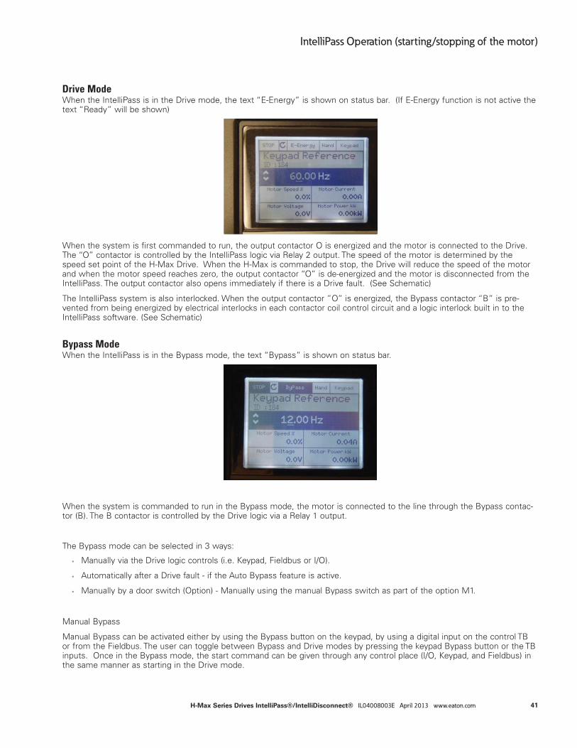
Drive ModeWhen the IntelliPass is in the Drive mode, the text “E-Energy” is shown on status bar. (If E-Energy function is not active the text “Ready” will be shown)
When the system is first commanded to run, the output contactor O is energized and the motor is connected to the Drive. The “O” contactor is controlled by the IntelliPass logic via Relay 2 output. The speed of the motor is determined by the speed set point of the H-Max Drive. When the H-Max is commanded to stop, the Drive will reduce the speed of the motor and when the motor speed reaches zero, the output contactor “O” is de-energized and the motor is disconnected from the IntelliPass. The output contactor also opens immediately if there is a Drive fault. (See Schematic)
The IntelliPass system is also interlocked. When the output contactor ”O” is energized, the Bypass contactor “B” is pre-vented from being energized by electrical interlocks in each contactor coil control circuit and a logic interlock built in to the IntelliPass software. (See Schematic)
Bypass ModeWhen the IntelliPass is in the Bypass mode, the text “Bypass” is shown on status bar.
When the system is commanded to run in the Bypass mode, the motor is connected to the line through the Bypass contac-tor (B). The B contactor is controlled by the Drive logic via a Relay 1 output.
The Bypass mode can be selected in 3 ways:
• Manually via the Drive logic controls (i.e. Keypad, Fieldbus or I/O).
• Automatically after a Drive fault - if the Auto Bypass feature is active.
• Manually by a door switch (Option) - Manually using the manual Bypass switch as part of the option M1.
Manual Bypass
Manual Bypass can be activated either by using the Bypass button on the keypad, by using a digital input on the control TB or from the Fieldbus. The user can toggle between Bypass and Drive modes by pressing the keypad Bypass button or the TB inputs. Once in the Bypass mode, the start command can be given through any control place (I/O, Keypad, and Fieldbus) in the same manner as starting in the Drive mode.
IntelliPass Operation (starting/stopping of the motor)41
IntelliPass Operation (starting/stopping of the motor)
H-Max Series Drives IntelliPass®/IntelliDisconnect® IL04008003E April 2013 www.eaton.com
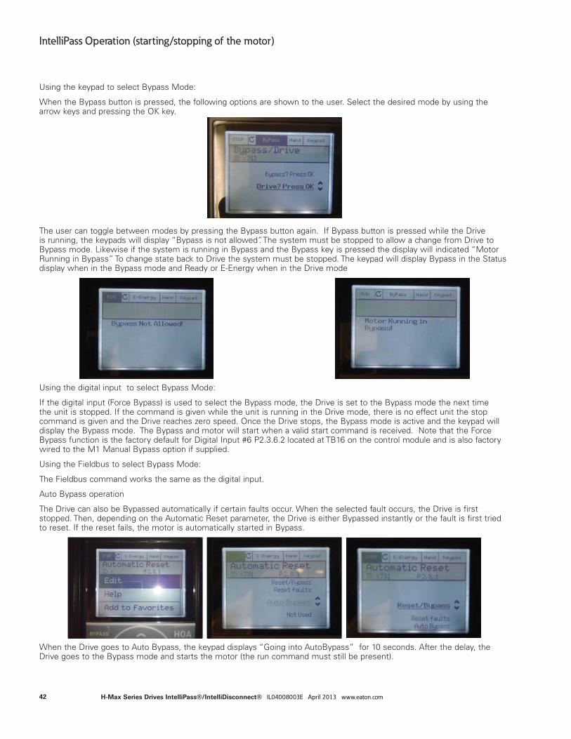
Using the keypad to select Bypass Mode:
When the Bypass button is pressed, the following options are shown to the user. Select the desired mode by using the arrow keys and pressing the OK key.
The user can toggle between modes by pressing the Bypass button again. If Bypass button is pressed while the Drive is running, the keypads will display “Bypass is not allowed”. The system must be stopped to allow a change from Drive to Bypass mode. Likewise if the system is running in Bypass and the Bypass key is pressed the display will indicated “Motor Running in Bypass” To change state back to Drive the system must be stopped. The keypad will display Bypass in the Status display when in the Bypass mode and Ready or E-Energy when in the Drive mode
Using the digital input to select Bypass Mode:
If the digital input (Force Bypass) is used to select the Bypass mode, the Drive is set to the Bypass mode the next time the unit is stopped. If the command is given while the unit is running in the Drive mode, there is no effect unit the stop command is given and the Drive reaches zero speed. Once the Drive stops, the Bypass mode is active and the keypad will display the Bypass mode. The Bypass and motor will start when a valid start command is received. Note that the Force Bypass function is the factory default for Digital Input #6 P2.3.6.2 located at TB16 on the control module and is also factory wired to the M1 Manual Bypass option if supplied.
Using the Fieldbus to select Bypass Mode:
The Fieldbus command works the same as the digital input.
Auto Bypass operation
The Drive can also be Bypassed automatically if certain faults occur. When the selected fault occurs, the Drive is first stopped. Then, depending on the Automatic Reset parameter, the Drive is either Bypassed instantly or the fault is first tried to reset. If the reset fails, the motor is automatically started in Bypass.
When the Drive goes to Auto Bypass, the keypad displays “Going into AutoBypass” for 10 seconds. After the delay, the Drive goes to the Bypass mode and starts the motor (the run command must still be present).
42
IntelliPass Operation (starting/stopping of the motor)
H-Max Series Drives IntelliPass®/IntelliDisconnect® IL04008003E April 2013 www.eaton.com
When the fault condition is not active, the Drive is set back to Drive mode automatically and the Bypass running signal is reset. The Drive returns to the normal operation.
Automatic Reset selections 0 = Not used
1 =Auto Bypass (Visible only if Bypass is enabled)
2 = Reset faults
3 = Reset/Bypass (Visible only if Bypass is enabled)
Activate the Automatic Reset functions with this parameter.
For option 1, if the Drive faults, the Drive switches automatically to Bypass and leaves the fault active on the Drive. For option 3, the Drive will first try to auto reset the faults but if not successful, it will then switch to Bypass. Option 2 just tries to reset the fault without going into Bypass. See the application manual for more information on Auto reset operation.
Manual Bypass (forced) - M1 option
The IntelliPass also has a forced manual Bypass option. This is controlled by a door mounted Drive/Off /Bypass switch. The door switch will start the motor in Bypass immediately regardless of Drive logic or state. This switch manually overrides the system (keypad) and forces the unit into Bypass mode even if the Drive is in operative or removed from the system - See schematic and the factory wired option section for more information.
HOA Control- IntelliPassThe Keypad HOA button is used for fast and easy changing between Hand, Off and Auto control places the change the speed set point source. HOA Control works in both the Drive and Bypass modes of operation. However speed set point has no functions when in Bypass since the motor runs full speed across the line.
Control place is defined as the location from where the Drive or Bypass is started and stopped. Hand and Auto are two dif-ferent control places.
There are four parameters for selecting a control source and reference source for them: P2.1.3 HOA Control Source, P2.1.4 Start Source Hand, P2.1.5 Speed Set point Hand, P2.1.6 Start Source Auto & P2.1.7 Speed Set point Auto. The Start Source selections are: Keypad, I/O Terminal, I/O 3-wire & Fieldbus Ctrl. For the Drive mode, the Speed set point the selections are: Keypad Ref, Fieldbus, AI1, AI2, AI1+AI2, & PID1 (if PID is activated). See Quick Start Guide MN04008005E or Application Manual MN04008006E for more information.
43
IntelliPass Operation (starting/stopping of the motor)
H-Max Series Drives IntelliPass®/IntelliDisconnect® IL04008003E April 2013 www.eaton.com
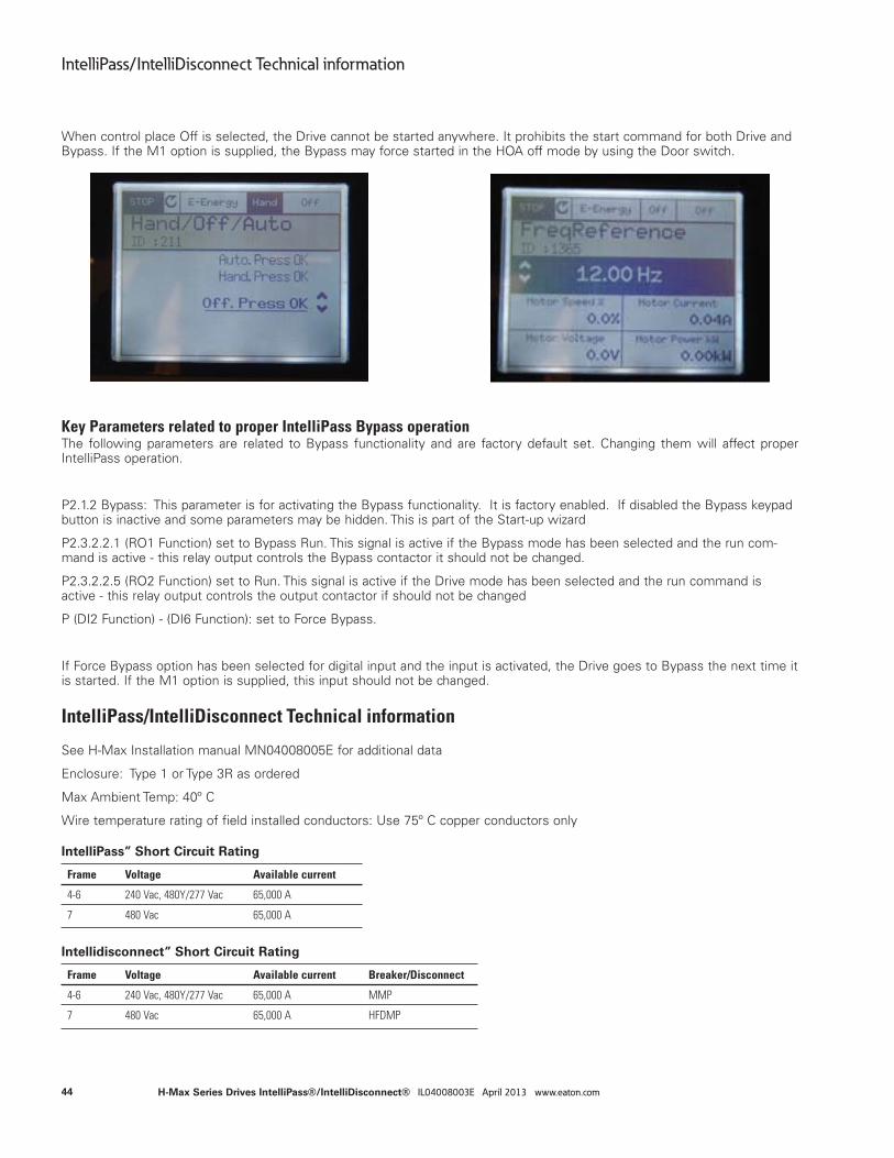
When control place Off is selected, the Drive cannot be started anywhere. It prohibits the start command for both Drive and Bypass. If the M1 option is supplied, the Bypass may force started in the HOA off mode by using the Door switch.
Key Parameters related to proper IntelliPass Bypass operationThe following parameters are related to Bypass functionality and are factory default set. Changing them will affect proper IntelliPass operation.
P2.1.2 Bypass: This parameter is for activating the Bypass functionality. It is factory enabled. If disabled the Bypass keypad button is inactive and some parameters may be hidden. This is part of the Start-up wizard
P2.3.2.2.1 (RO1 Function) set to Bypass Run. This signal is active if the Bypass mode has been selected and the run com-mand is active - this relay output controls the Bypass contactor it should not be changed.
P2.3.2.2.5 (RO2 Function) set to Run. This signal is active if the Drive mode has been selected and the run command is active - this relay output controls the output contactor if should not be changed
P (DI2 Function) - (DI6 Function): set to Force Bypass.
If Force Bypass option has been selected for digital input and the input is activated, the Drive goes to Bypass the next time it is started. If the M1 option is supplied, this input should not be changed.
IntelliPass” Short Circuit Rating
Frame Voltage Available current
4-6 240 Vac, 480Y/277 Vac 65,000 A
7 480 Vac 65,000 A
Intellidisconnect” Short Circuit Rating
Frame Voltage Available current Breaker/Disconnect
4-6 240 Vac, 480Y/277 Vac 65,000 A MMP
7 480 Vac 65,000 A HFDMP
IntelliPass/IntelliDisconnect Technical information
See H-Max Installation manual MN04008005E for additional data
Enclosure: Type 1 or Type 3R as ordered
Max Ambient Temp: 40o C
Wire temperature rating of field installed conductors: Use 75o C copper conductors only
44
IntelliPass/IntelliDisconnect Technical information
H-Max Series Drives IntelliPass®/IntelliDisconnect® IL04008003E April 2013 www.eaton.com

45
IntelliPass/IntelliDisconnect Technical information
H-Max Series Drives IntelliPass®/IntelliDisconnect® IL04008003E April 2013 www.eaton.com

Eaton CorporationElectrical Sector1111 Superior Ave.Cleveland, OH 44114United States877-ETN-CARE (877-386-2273)Eaton.com
© 2012 Eaton CorporationAll Rights ReservedPublication No. IL04008003E / 004April 2013
All trademarks are property of their respective owners.
IntelliPass/IntelliDisconnect Technical information


![Home Page []0.7000 max 35 min 65 max 85 max 125 max 1 50 max I .5 max I max NO 1 STRIP 75 max 25 min 0.03 max 15 max 40 max Specific Gravity @ 150C Distillation:](https://img.pdfslide.net/doc/110x75/5f201a8f5d3b4e45a5210259/home-page-07000-max-35-min-65-max-85-max-125-max-1-50-max-i-5-max-i-max-no.jpg)