Embed Size (px)
Citation preview
0
GPO PRiCE S
OTS PRICE(S) $
P P Hard copy (HC) I . Y J
Microfiche (MF) 13" i j
-h
RESEARCH MEMORANDUM
'ATNGLESS MISSILE CCNFIGUM-TICN AT
MACH NUMBERS FROM 3.0 TO 6.3
NATIONAL ADVl SORY COM M ITTEE FOR AERONAUTICS
. D NACA RM
NATIONAL ADVISORY COMMITTEE FOR AERONAUTICS
- Y RESEARCH MEMORANDUM
AN EXPERIMENTAL INVESTIGATION OF THE STATIC LONGITUDINAL
STABILITY AND CONTROL CHARACTERISTICS OF A
WINGL;ESS MISSIIX CONFIGURATION AT
MACH NUMBERS FROM 3.0 TO 6.3
By Hermilo R. Gloria
SUMMARY \ - Q y e p
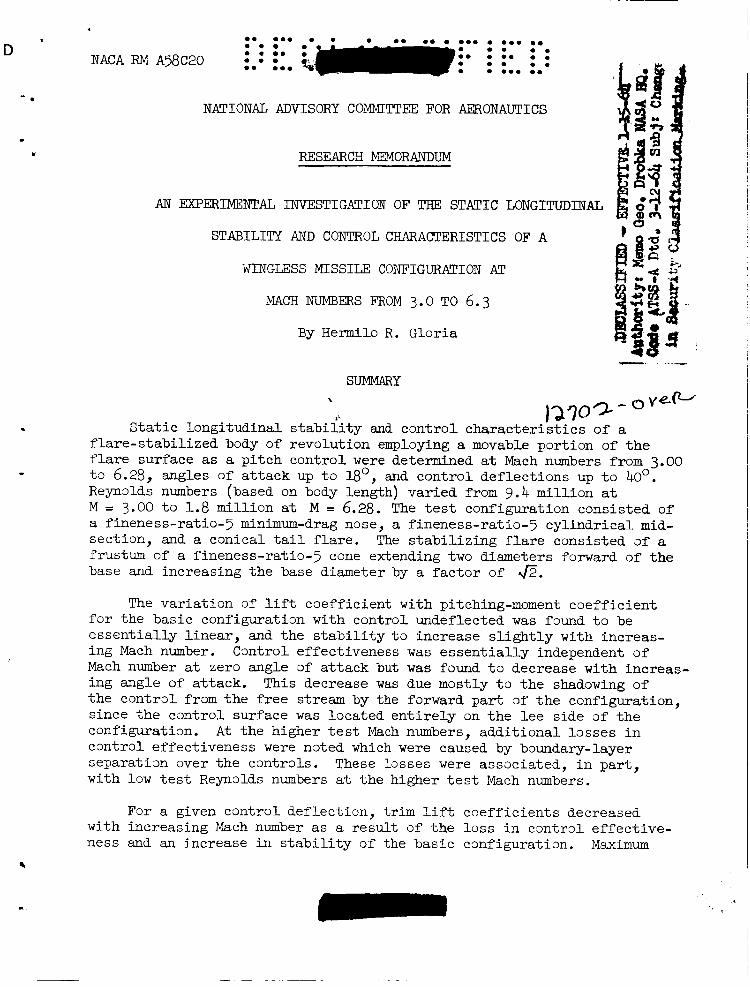
#' 12309- Static longitudinal stability a d control characteristics of a
flare-stabilized body of revolution employing a movable portion of the flare surface as a pitch control were determined at Mach numbers from 3.00 to 6.28, angles of attack up to Bo, and control deflections up to 40°. Reynolds numbers (based on body length) varied from 9.4 million at M = 3.00 to 1.8 million at M = 6.28. The test configuration consisted of a fineness-ratio-5 minimum-drag nose, a fineness-ratio-? cylindrical mid- section, and a conical tail flare. The stabilizing flare consisted of a frustum of a fineness-ratio-? cone extending two diameters forward of the base and increasing the base diameter by a factor of @.
The variation of lift coefficient with pitching-moment coefficient for the basic configuration with control undeflected was found to be essentially linear, and the stability to increase slightly with increas- ing Mach number. Mach number at zero angle of attack but was found to decrease with increas- ing angle of attack. the control fram the free stream by the forward part af the configuration, since the control surface was located entirely on the lee side of the configuration. At the higher test Mach numbers, additional losses in cmtrol effectiveness were noted which were caused by bwndary-layer separation over the controls. These losses were associated, in part, with low test Reynalds numbers at the higher test Mach numbers.
Control effectiveness was essentially independent of
This decrease was due mostly to the shadowing of
For a given control deflection, trim lift coefficients decreased with increasing Mach number as a result of the l o s s in cmtrol effective- ness and an increase in stability of the basic configuration. Maximum
.
2
a . trim lift-drag ratios between 2 and 2.5 were obtained and were about 30 percent lower than the maximum lift-drag ratios of the basic configu- ration. I
- . At zero angle of attack, predictions with impact theory were found
to be in good agreement with experimental results for incremental forces due to control deflection. At angle of attack, however, impact theory underestimated control effectiveness at low Mach numbers and effectiveness at high Mach numbers.
INTRODUCTION
In the study of missile configurations suitable for flight at hyper- sonic speeds, considerable attention has been given to the wingless or all-body missile (see, e.g., refs. 1, 2, 3, and 4). Among the advantages attributed to these configuratims are (1) a less severe problem of aero- dynamic heating because of the absence of thin planar surfaces; and (2) aerodynamic force characteristics which tend to be independent of Mach number. was stabilized by a conical flare at the base with control provided by deflectable sections of the body surface forward of the stabilizing flare. While the aerodynamic characteristics of this configuration compared favorably with those of a configuration employing planar surfaces for stability and control, the wingless missile tested did display certain undesirable properties. ciency (i.e., lift-drag ratio) and reduced control effectiveness at low control deflection due to control-flare interference. Suggestions given in reference 1 for remedying these difficulties were that a more slender nose and stabilizing flare be employed to reduce drag and increase lift- drag ratio; to improve cmtrol effectiveness, it was.suggested that the control surfaces be incorporated as part of the stabilizing flare. configuration embodying these suggestions is the subject of the present report.
In reference 1, a wingless configuration was studied which
Among these are relatively low aerodynamic effi-
A
Force and moment characteristics as well as control forces are obtained for various flap deflections at Mach numbers from 3.00 to 6.28. Experimentally determined forces are compared with predictions of theory.
NOTATION
A cross-sectional area of cylindrical mid-body, sq in.
Ac control-surface plan area, sq in.
CD drag drag coefficient, - SA
A
- * ch
. CL
c,
CN
Nf C
d
2
2f
M
control hinge-moment coefficient about control leading edge, hinge moment
9A, 2f lift lift coefficient, - SA
pitching moment SA 2
pitching-moment coefficient about 0.47 2,
normal force SA
normal-force coefficient,
control normal-force coefficient (normal to control surface), control normal force
SA, diameter of cylindrical mid-body, in.
body length, in.
control surface length, in.
free- stream Mach number
free-stream dynamic pressure
angle of attack, deg
control deflection angle,.measured from flare surface, deg
3
APPARATUS AND TESTS
Tests were conducted in the Ames 10- by &inch supersonic wind tunnel, which is described in detail in reference 5. and moments acting on the test model were measured by strain-gage bal- ances. The model was supported fromthe rear by a sting that was shrouded to within 0.040 inch of the model base, thereby eliminating, for all prac- tical purposes, aerodynamic laads on the supp~rts. Base pressures were measured in all tests and the resultant base forces (referred ta free- stream static pressure) were subtracted from the measured axial forces.
Aerodynamic forces
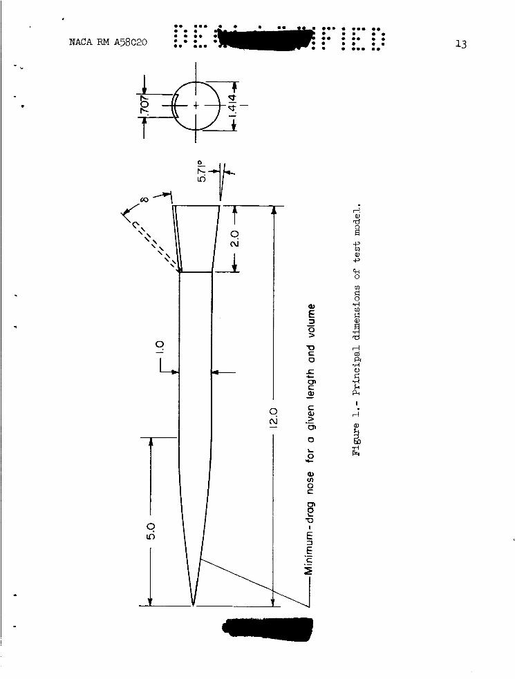
Principal dimensions of the test madel are shown in figure 1. The bady of the configuration cons.ists of three sectims. The nDse section is a minimum-drag body for given length and valume having a fineness ratio of 5 (ref. 6). table I. The middle section is cyllndrical and also has a fineness ratio
Coordinates 3fthe nose section are given in
4
e. ... . 0. . . .. .. . . . ... 0 . I
0 . 0 . 0 . . . .. . .. . .. 0 . 0 . .. 0. . . . . .. . . ... .. NACA RM A58C20
a - of 5. two cylinder diameters long, that increases the mid-body diameter by 1.41. The control surface is a portion of the top of the flare surface, 0.71- cylinder diameters wide, and it extends the full length of the tail flare. It is deflected above the flare surface from a hinge line located at the cylinder-flare juncture.
angles of attack up to IBo, and control deflections up to 40' above the flare surface. are as follows:
The flared tail section is a frustum of a fineness-ratio-? cone,
Tests were conducted at Mach numbers of 3.00, 4.24, 5.05, and 6.28,
The free-stream Reynolds numbers based on body length
Reynalds number, M millions -
3.00 9.36 4.24 8.64 5.05 4.20 6.28 1.80
Variations in free-stream Mach number did not exceed k0.02 at Mach Deviations in free- numbers from 3.00 to 5.05 and f0.04 at
stream Reynolds number did not exceed f5O,OOO from the values given pre- viously. did not exceed k0.2'.
M = 6.28.
The estimated error in angle of attack and control deflection
Precision of the experimental results is affected by uncertainties in measured forces, moments, and base pressures as well as in the deter- mination of free-stream dynamic pressure and angle of attack. These uncertainties resulted in maximum possible errors in the aerodynamic force and moment coefficients as shown in the following table:
RESULTS AND DISCUSSION
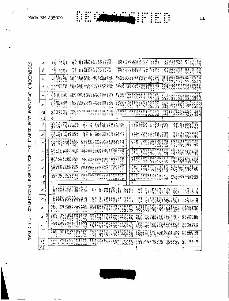
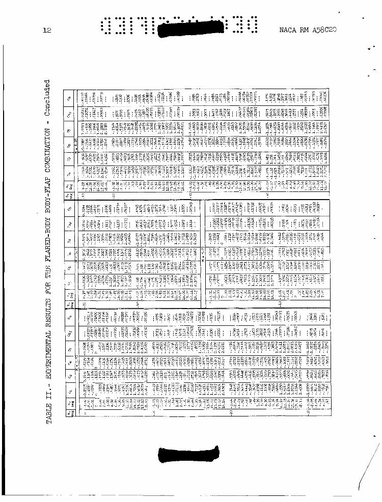
E,xperimental results of the present investigation are given in table I1 f x the complete range of test variables. data are also presented in graphical form in figures 2 through 6.
Portions of these
m m m m m m m a 8 m a m a a m 8 0 8 8 o m a m
. m a m a
am m m m m m m a m m a o m
NACA RM A58C20 :; 5
- c Control-Body Combination Characteristics
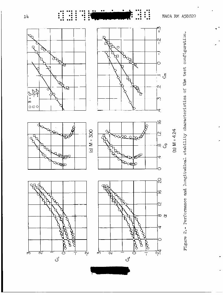
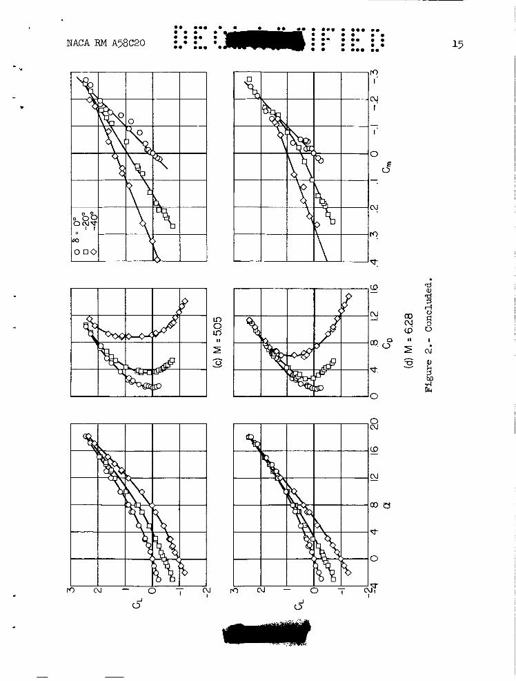
The variations of lift coefficient with angle of attack, drag . coefficient, and pitching-moment coefficient are presented in figure 2 for control deflections of Oo, 20°, and 40' and for all four test Mach numbers. coefficient w i t h ahgle of attack is seen to be relatively independent of Mach number. Similarly, the stability characteristics of the basic con- figuration, as demonstrated by the variation of lift coefficient with pitching-moment coefficient, show only a s m a l l change with Mach number. For example, the aerodynamic center moves only slightly rearward from 51 percent of the body length aft of the nose at at M = 6.28. In addition, the stability characteristics of the basic configuration are essentially linear. however, the stability characteristics become more nonlinear and there is a greater variation in aerodynamic characteristics with Mach number, indicating changes in control effectiveness.
For the basic configuration (6 = Oo) , the variation of lift
M = 3.00 to 54 percent
When the control is deflected,
Control Effectiveness
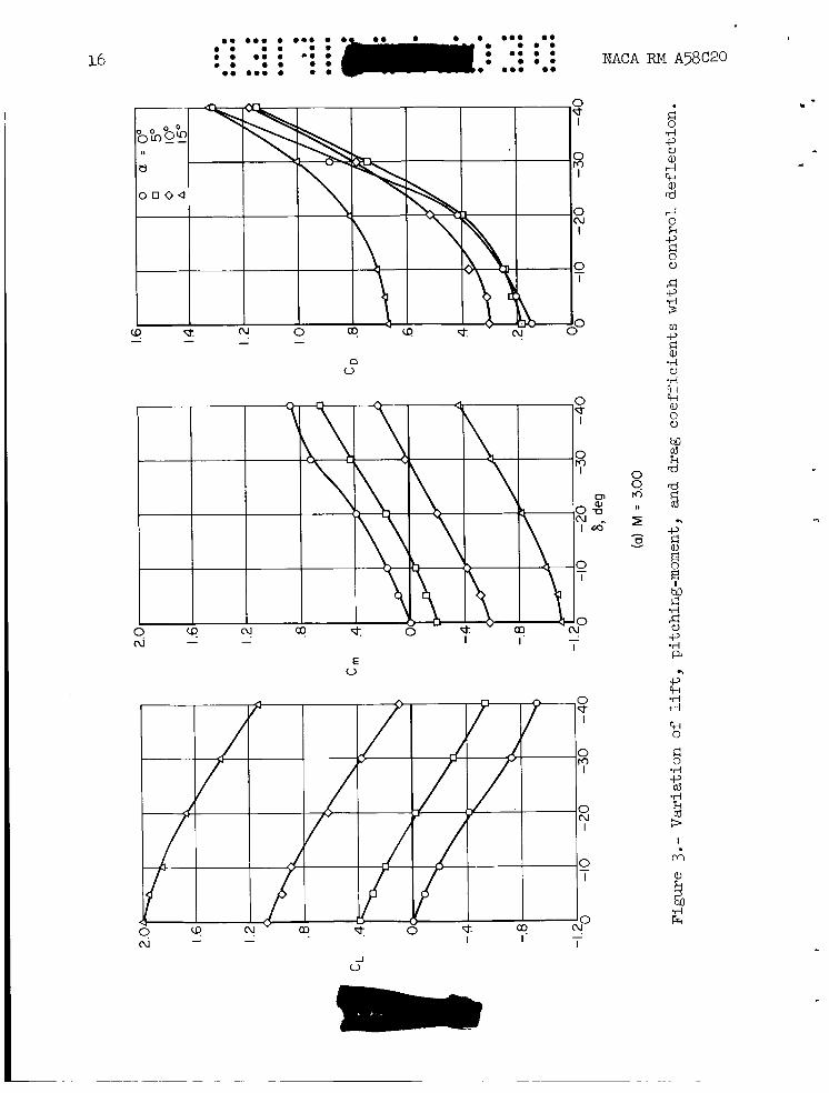
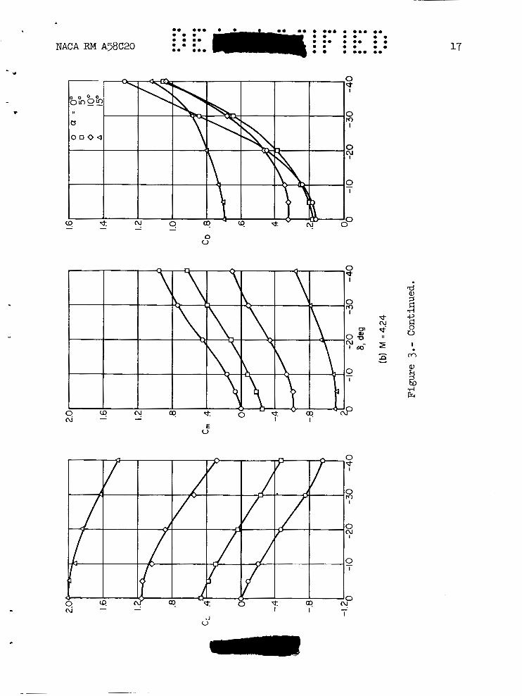
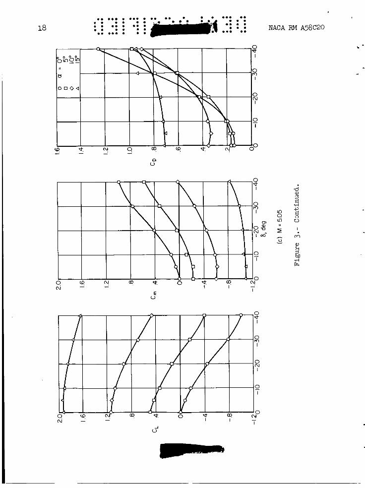
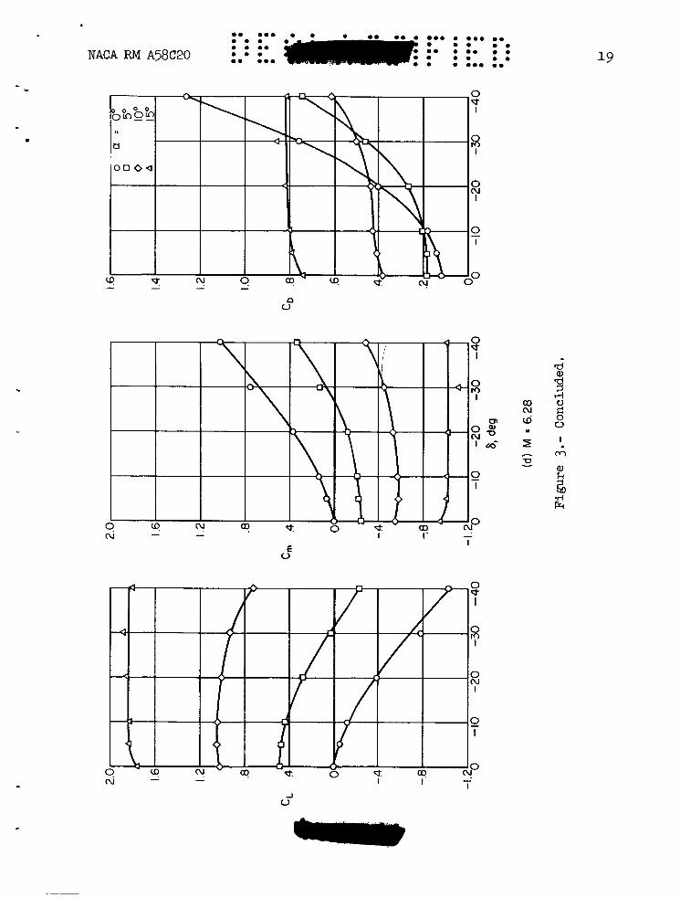
.. The variations of lift, pitching-moment, and drag coefficients with
control deflections are presented in figure 3 for all test Mach numbers and for several angles of attack. of the body flap control on CL, Cm, and CD is maintained throughout the test range of control deflections. control does not show the marked decrease in effectiveness with increas- ing Mach number that is so characteristic of planar controls; in fact, a small increase in effectiveness is indicated at the larger control deflec- tions. When the configuration is inclined, however, there is a loss in cmtrol effectiveness, particularly at the smaller control deflections. This l o s s is more pronounced both at higher angles of attack and at higher Mach nun-oers. tually ineffective throughout the test range of control deflections. Part of the lass in control effectiveness with angle of attack is undmbtedly due t3 the fact that the control is shadowed from the free stream by the forward part of the configuration, since the control is located on the top surface of the flare. Thus, the control operates in the wake of the body or at least in a region of reduced dynamic pressure.
lA simple method for increasing the attractiveness of the bady-flap cmtrol at angle of attack would involve the use of a flap on the hwer surface of the stabilizing flare coupled to the upper flap so as to retract into the flare as the upper cmtrol is e,xtended. Such a system would tend to reduce control hinge moments as well as increase effective- ness by reducing the stabilizing influence of the flare. This method was suggested in reference 1 and a similar configuration was investigated in reference 7. The present configuration did not involve the use of coupled flaps because 2f the limit in lower control travel imposed by the small flare angle.
At zero angle of attack, the effect
At this angle of attack, the
At M = 6.28 and a = 15', for example, the control is vir-
6
-. - L a . ... 0 .. a. 0 . . ... .. 0 0 0 . . . ... _ _ _ _ _ .
.. ... .. NACA RM ~ 5 8 ~ 2 0 0 . 0 . . While this effect would tend to increase with Mach number, it is not the only factor that would tend to reduce control effectiveness at the higher test Mach numbers. An additional loss is attributed to boundary-layer separation ahead of the control due, in part, to the lower test Reynolds numbers at the higher test Mach numbers. this phenomenon, a visual study was made of the flow in the region of the control surface.
For a better understanding of
Flow-Visualization Studies
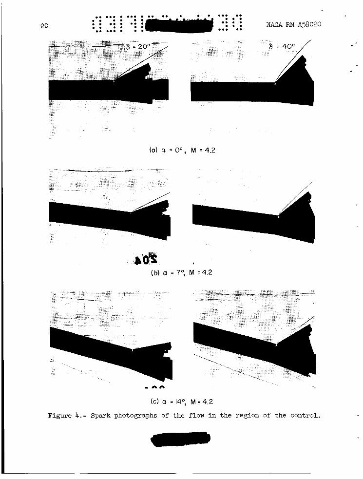
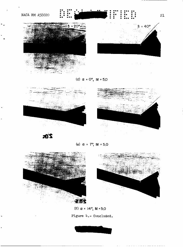
Spark shadowgraphs of the flow in the region of the control surface are presented in figure 4 for control deflections of 20' and 40°, angles of attack of Oo, 7 O , and 14O, and Mach numbers of 4.24 and 5.05. photographs for obtained f o r M = 3.00 and they show flow in the region of the control that is typical of the flow that occurs when there is little 31 no boundary-layer separation. In these cases, the body boundary layer is turbulent ahead of the body-control juncture and it passes thrmgh the shack wave produced by the control without appreciable separation. In contrast, at number is lower, the boundary layer is laminar ahead of the body-control juncture and extensive regions of separation occur. At angles of attack of 7" and 14O, for example, the separated region tends to envelope a large pcxrtion of the control surface. where the test Reynolds number is still lower, showed regions of separa- tion which were even more extensive than those found at M = 5.05. It is apparent that if the flow over the control is separated, then the effectiveness of the control will be markedly reduced. Thus the photo- graphs shown in figure 4 tend to explain the added loss in control effectiveness at high Mach numbers mentioned in the previous section. It should be noted, however, that the extent of flow separation is strongly dependent on the location of transition and thus on the Reynolds number (see ref. 8). separated flow would undoubtedly be smaller, but it would not be expected to disappear. In any event, it is evident that boundary-layer separation can have large effects on the stability and control characteristics of configurations which employ flares for stability and deflectable body segments for control. In this connection, it should be noted that part of the rearward movement of aerodynamic center at the higher Mach numbers mentioned previously can also be associated with the effects of separation ahead of the stabilizing flare (see ref. 9).
The M = 4.24 (figs. 4(a), (b), and (c)) are similar to those
M = 5.05 (figs. 4(d), (e), and (f)) where the test Reynolds
Similar photographs for M = 6.28,
At higher test Reynolds numbers, the region of
Control Forces and Moments
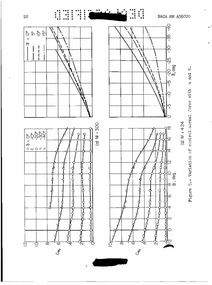
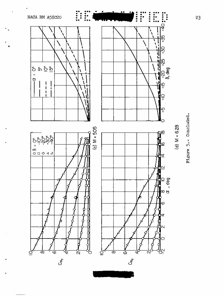
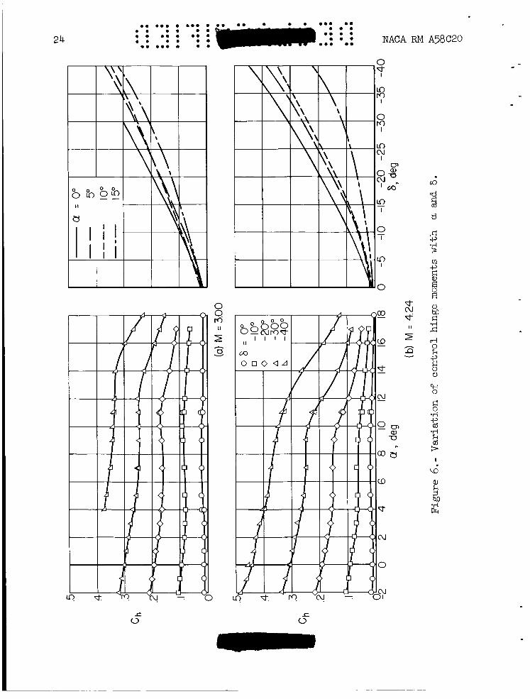
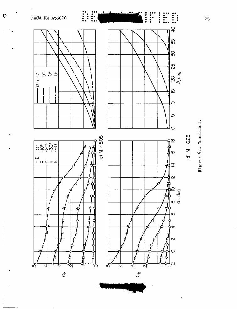
The variation of control n3rmal-force and hinge-mament coefficients with control deflection are presented in figures 5 and 6. In general,
0 0.0 0 0 0 . 0 0 0 . 0 . 0 0 0 0 . 0 0 0 0 0
0 0 0 0 0 0 0.
0 0 0.0 0 0 . 0 0 .
0 . 0.0 0 . NACA RM A58C20 : : :' : 0 . 0 0 0 . 7
these data corroborate the control-effectiveness results. the variations of control normal-force and hinge-moment coefficients with control deflection at
the reduction in forces and moments experienced by the control is clearly evident. no aerodynamic balance, the hinge-moment coefficients are relatively large, at least when the control is effective. These large hinge moments may not necessarily be as big a disadvantage as for a wing trailing-edge control, however, since the mechanical problems associated with actuating the control will be reduced as a result of the location of the control.
For example, - c
a = 0' are relatively independent of Mach number. 0 In additian, at higher angles of attack and at the higher Mach numbers,
It should also be noted, however, that since the control has
Trim Characteristics
I -
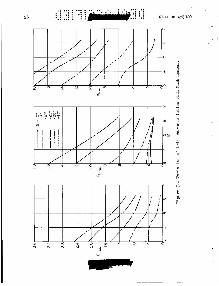
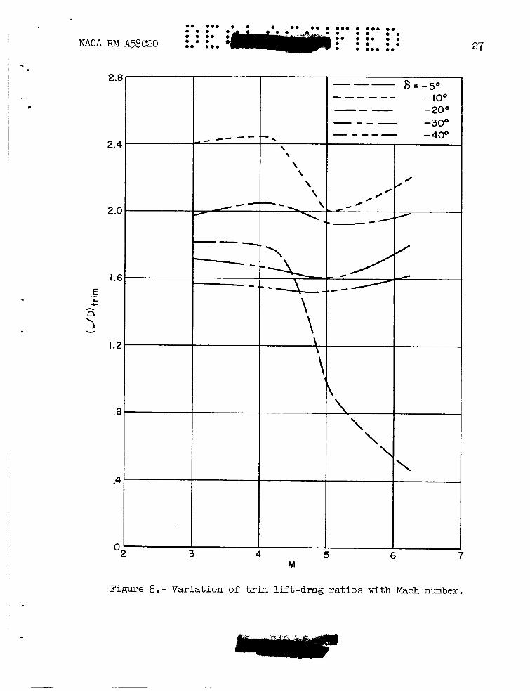
From the results presented previously, the aerodynamic character- istics of the control-body combination in trimmed flight have been deter- mined. gravity was assumed to be located at 47 percent of the body length aft of the nose. diameter at For the selected center-of-gravity location, the aerodynamic characteristics of the trimmed configuration are shown as a function of Mach number for several control deflections in figure 7. One of the msst pronounced trends evident in this figure is the decrease with increasing Mach number in trim lift coefficient and angle of attack that can be obtained with a given con- trsl deflection. For example, with a control deflectim of 403, the trim lift coefficient and angle of attack decrease from about 2.5 and 22O, respectively, at M = 3.00 to about 1.0 and 1l0, respectively, at M = 6.28. M = 3.00 was beyond the range of experimental results and was estimated by extrapolatian of the data to higher angles of attack.) A large part of this reduction is, of course, associated with the l o s s in control effectiveness previously discussed; h3wever, the increase in stability with Mach number is also a factor. Trim lift-drag ratios are shown as a function of Mach number for various contr3l deflections in figure 8. It is nsted that the highest ratios, between 2 and 2.5, are obtained with lo3 csntrol deflection. These values are about 30 percent lower than the maximum lift-drag ratios of the untrimmed basic configuration.
In the determination of these characteristics, the center of
With this location, the static margin varies from 1/8 body M = 3.00 to 1/2 body diameter at M = 6.28.
(Note that the trim point at
Comparisons With Themetical Predictions
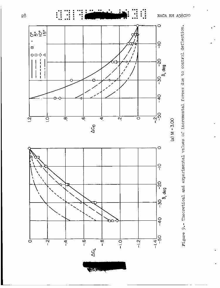
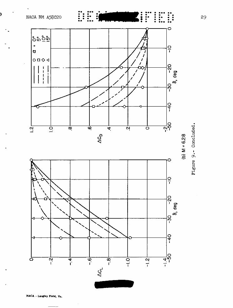
The incremental lift and drag coefficients due to control deflection, ACL and ACD, have been estimated with the aid of impact thesry (see, e.g., ref. 10). These estimates are compared with experimental results for several angles of attack at M = 3.00 and M = 6.28 in figure 9. In
8
application of the theory, the shadowing effect of the forebody on the control was considered by assuming zero pressure coefficient on portions of the control shielded from the air stream by the projection of the forebody at angle of attack. of impact theory are in good agreement with experimental results. M = 3.00, the control is more effective at angle of attack than is indi- cated by theory. It appears that at this Mach number, the forebody does not shadow the control to any appreciable extent. z o z t r o l is less effective at angle of attack than predicted theoretically. While the shadowing effect undoubtedly increases with Mach number, much of the discrepancy is associated with the effects of boundary-layer separation which were not considered in the theory.
At zero angle of attack, the predictions At
At M = 6.28, the
*. = I
SUMMARY OF RESULTS
Static longitudinal stability and control characteristics of a flare-stabilized body of revolution employing a portion of the flare surface as a pitch control have been determined at Mach numbers from 3.00 to 6.28, angles of attack up to 18O, and control deflections up to 40'. Reynolds numbers (based on body length) varied from 9.4 million at M = 3.00 to 1.8 million at are as follows:
M = 6.28. The results of this investigation
1. For the basic confi@ration with control undeflected, the varia- tion of lift coefficient with pitching-moment coefficient is essentially linear and stability increases slightly with increasing Mach number.
2. At zero angle of attack, control effectiveness is maintained throughout the test range of control deflections and it is essentially independent of Mach number. When the configuratim is inclined, control effectiveness is decreased. Part of the l o s s in effectiveness is due to shadowing of the control from the free stream by the body of the config- uration. Additional losses in control effectiveness occur at the higher test Mach numbers as a result of separation of the boundary layer ahead of the control. numbers at the higher test Mach numbers.
This separation is associated with the law test Reynolds
3. For a given control deflection, trim lift coefficients decrease with increasing Mach number because of losses in control effectiveness and because of an increase in the stability of the basic emfiguration. Trim lift-drag ratios between 2 and 2.5 can be obtained with the test configuration. These values are abaut 30 percent bwer than the ratios for the untrimmed basic configuration.
4. Incremental forces due t3 cJntrDl deflection can be estimated at zero angle of attack by the use of impact theory. At angle 3f attack
‘ b however, impact theory tends to underestimate control effectiveness at low Mach numbers and overestimates control effectiveness at high Mach numbers.
Ames Aeronautical Laboratory National Advisory Committee for Aeronautics
Moffett Field, Calif., Mar. 20, 1958
REFERENCES
.
9
1. Eggers, A. J., Jr., and Syvertson, Clarence A.: Experimental Inves- tigation of a Body Flare for Obtaining Pitch Stability and a Body Flap f o r Obtaining Pitch Control in Hy-personic Flight. NACA RM A54J13, 1955.
2. Lessing, Henry C., and Reese, David E., Jr.: NACA RM A55LO6, 1956.
A Simulation Study of a Wingless Missile.
3 . Becker, J. V., and Korycinski, Peter F.: Heat Transfer and Pressure Distribution at a Mach Number of 6.8 on Bodies With Conical Flares and Extensive Flow Separation.
Lateral Stability Parameters of Three Flared-Skirt Two-Stage Missile Configurations at a Mach Number of 6.86.
Supersonic Wind Tunnel.
of Revslution Having Minimum Drag at High Supersonic Airspeeds. NACA Rep. 1306, 1957.
less Missile Configurations at Supersonic Speeds. 1958-
gation of Separated Flows in Supersonic and Subsmic Streams With Emphasis on the Effect of Transition.
Effects of Boundary- Layer Separation on Normal Force and Center of Pressure of a Cone- Cylinder Model With a Large Base Flare at Mach Numbers From 3.00 to 6.28.
Bodies of Revolution in Hy-personic Flow. Jour. Aero. Sci., vol. 17, no. n, NOV. 1950, pp. 675-690.
NACA RM ~56~22, 1956. 4. Penland, Jim A., and Carroll, C. Maria: Static Longitudinal and
XACA RM L57D15, 1957. 5. Eggers, A. J., Jr., and Nothwang, George J. : The Ames 10- by 14-Inch
6. NACA TN 3095, 1954.
Eggers, A. J., Jr., Resnikoff, Meyer M., and Dennis, David H.: Bodies
(Supersedes NACA TN 3666) 7. Reese, David E., Jr.: A Wind-Tunnel Investigation of Several Wing-
NACA RM A57J22,
Investi- 8. Chapman, Dean R., Kuehn, Donald M., and Larson, Howard K.:
NACA TN 3869, 1957. 9. Dennis, David H., and Syvertson, Clarence A,:
NACA RM A55HO9, 1-93?. 10. Grimminger, G., Williams, E. P., and Young, G. B. W.: Lift on Inclined
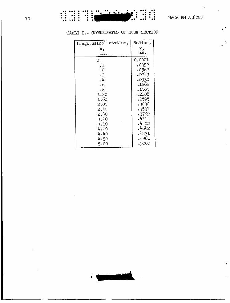
TmLE I.- COORDINATES OF NOSE SECTION
Longitudinal s t a t ion , *, in .
0 .1 .2 * 3 .4 .6 .8
1.20 1.60 2.00 2.40 2.80 3.20 3.60 4.00 4.40 4.80 5.00
Radius, Y, in .
10
0.0021 0352
.0562 0749 0930
.1262 1565
.2108 2595 3030 3531 3789
.4114 ,4402 .4642 .4831
.5000
.4961
NACA RM A58C20
C
.
0. 0.. . . .. 0. . 0.. . 0.. 0 . 0 . . . 0 . 0 . 0 . .... . 8 0 . . 0. . . 0 8 . . 0 . 0 . 0 . 0 . 0.. orno 0.
11
0 f
12
0.. 0 . ............ :: .:: 0 : : : . 0 . . NACA RM A58C20 0.. 0 . * * 0 . ........
9 In
0
0 L
+
k 0
a rl Ld
I
rl
14
I 1 1 - 1 I
* I
E 0
t V
..
c
0. 0 . 0 0.0 io- 0 0 0 . .** 0 0 . ... 0 . .. 0 0 0. 0 0 . ) 0 0 0 0 . 0 . 0 0 . 0 . 0 .
0 0 0 0.0 0 0 NACA RM A58C20 0 0 0 0 0 0
ixi
I I I r I I
E 0
0 0
16 .. . *e . .eo . .e. e. e ... . e . . . . . e . . ... .. e . . e .. . e e . . C . e
. e .. .. 0. e.. . . e
NACA RM A58C20
h
E 0
I
Y
v
"
;m*
- 0 0 0 0 . # 0 0 . 0 0 0 0 0 0 0 0 0 a. 0 0 0 0 0 0 0 0 0 0
0 o m 0 0 0
0 a.
NACA RM A38C20 0 0 0.0
V
u *. I
0 ? CY - 0
I J
V
18
A 0 d- I
c
V
J 0
20
(a) 01 = Oo, M = 4.2
I
(b) 01 = 7O, M ~ 4 . 2
I, A A
( C ) O1 = 14O, M = 4.2
Figure 4.- Spark photographs of the flow in the region of the control.
co 0 0 0 0 0 0 0.0 0 0.. 0 0
* a 0 0 0 0 . 0 0
0 0 0 . 0 . 0 0 0 0 0 0 0 0
0 0 0 0 0 0 0 0 0 0 0 0 0 NACA RM A58C20 21
(d) = Oo, M = 5.0
_ _ . / .. . . . 11
(e ) u = 7O, M = 5.0
(f) = 1 4 O , M =5.0
Figure 4.- Concluded.
c
c
i
'c
..
c
24
J
26 NACA RM A58C20
27
c
E .- L c
A
0 J \
Y
4 5 M
6 7
Figure 8.- Variation of trim lif t -drag r a t io s w i t h Mach number.
28
0 . 0 . . . 0.. . 0 . 0 . . . . ... 0 .
NACA . . . e . 0 . . ... 0 .
0 . 0 . . . . 0 . 0 . 0 . * . .
0 . 0 . . . . RM A58C20
0 0 t4
I II
h
c3 v
. 0.. . 0.0
e 0. . 0. 0 . 0 . 0 . . 0..
0 . . . . 0. 0 . 0 m. ..e
NACA RM A58C20 1
n 0 -
0 d- I
NACA - Langley Fleld, va