Embed Size (px)
Citation preview

12.03.2M(H)
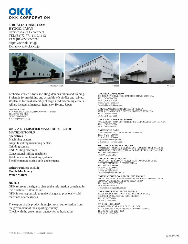
S-Plant W-PlantTechnical Center
INAGAWA PLANT:8-10, KITA-ITAMI, ITAMI, HYOGO 664-0831 JAPAN�TEL:(81)72-782-5121�FAX:(81)72-772-5156�E-mail:[email protected]
OKK USA CORPORATION100 REGENCY DRIVE, GLENDALE HEIGHTS, IL 60139 USA�TEL:(1)630-924-9000�FAX:(1)630-924-9010�http://www.okkcorp.com�E-mail:[email protected]
OKK USA WESTERN REGIONAL OFFICE(LA)17971 SKY PARK CIRCLE, SUITE D, IRVINE CA 92614 USA�TEL:(1)949-851-6800�FAX:(1)949-851-6888
OKK CANADA OFFICE(CANADA)7449 AUBURN ROAD, UNIT 1B HORNBY, ONTARIO, LOP 1EO, CANADA�TEL:(1)905-639-9784�FAX:(1)905-639-9503
OKK EUROPE GmbHHANSEMANNSTR, 33 41468 NEUSS GERMANY�TEL:(49)2131-29868-0�FAX:(49)2131-29868-41�http://www.okkeurope.com�E-mail:[email protected]
OKK(SHANGHAI) CO., LTD.ROOM C303, BUILDING 8, No.1221 HAMI ROAD CHANGNING�DISTRICT SHANGHAI P.C200335 CHINA�TEL:(86)21-62700930�FAX:(86)21-62700931�http://www.okk.com.cn�E-mail:[email protected]
OKK(SHANGHAI) CO., LTD. BEIJING BRANCHROOM 1905, EAST OCEAN CENTER, No.24A JIAN GUO MEN STREET �CHAO YANG DISTRICT, BEIJING, 100004 CHINA�TEL:(86)10-6515-0502/0702�FAX:(86)10-6515-5087�E-mail:[email protected]
OKK CORPORATION SEOUL BRANCH1203, E & C DREAM TOWER 8, 327-27, GASAN-DONG,�GEUMCHEON-GU, SEOUL, 153-023 KOREA�TEL:(82)2-855-0416�FAX:(82)2-855-0426
PT. OKK INDONESIAWISMA NUSANTARA BUILDING 12 FLOOR,�JL.M.H.THAMRIN No.59, JAKARTA. 10350 INDONESIA�TEL:(62)021-390-2563 / 2564�FAX:(62)021-390-2565
The export of this product is subject to an authorization from�the government of the exporting country.�Check with the government agency for authorization.
NOTE :�OKK reserves the right to change the information contained in�this brochure wihtout notice.�OKK is not responsible to make changes to previously sold�machines or accessories.
8-10, KITA-ITAMI, ITAMIHYOGO, JAPANOverseas Sales DepartmentTEL:(81)72-771-1112/1143FAX:(81)72-772-7592http://www.okk.co.jpE-mail:[email protected]
Technical center is for test cutting, demonstration and training.�S-plant is for machining and assembly of spindles and tables.�W-plant is for final assembly of large sized machining centers.�All are located at Inagawa, Itami city, Hyogo, Japan
OKK A DIVERSIFIED MANUFACTURER OF�MACHINE TOOLS�Specializes In:Machining centers�Graphite cutting machining centers�Grinding centers�CNC Milling machines�Conventional milling machines�Total die and mold making systems�Flexible manufacturing cells and systems
Other Products Include:�Textile Machinery�Water Maters
THAI OKK MACHINERY CO., LTD.�KUMTHORN HOLDING BUILDING 2ND FLOOR 897-897/1 RAMA III�ROAD BANGPONGPANG, YANNAWA, BANGKOK 10120 THAILAND�TEL:(66)2-683-2160-2�FAX:(66)2-683-2163
Printed with eco-friendly soy ink on recycled paper.
VB53_E.Q 12.3.22 2:59 PM ページ 1

XY Z
2,750mm
(108.27") 2,595mm (102.17")
Spindle rotating speed
100 to 20,000min-1
20m/min
Number of stored tools
30tools
2
Compact with higher Accuracy�and QualityCompact with higher Accuracy�and Quality
Advanced High-quality�Die & Mold Machining�Compact Vertical Machining Center
Advanced High-quality�Die & Mold Machining�Compact Vertical Machining Center
Machine travels X:1050mm(41.34"), Y:530mm(20.87"), Z axis:510mm(20.08")
Automobile interior part Material:NAK80
Loudspeaker Material:NAK80
Sample die Material:NAK80
Main Specification
Tool exchange time
(787.40ipm)
Space-saving with a Large Machining AreaDischarging chips to the left side of the machine, into the coolant tank located under the splash guarding has reduced the machine’s floor space to 2,595×2,750mm(102.17"×108.27"). Resulting in superior productivity per unit area.
※Machine picture may include optional accessories
Rapid traverse rate(X×Y×Z)
seconds (tool-to-tool)
1 VB53 VB53 2
VB53_E.Q 12.3.22 2:59 PM ページ 3

VERTICAL MCHINING CENTERFEATURES
High-accuracy Machining
Accuracy
HQ Control / Hyper HQ Control
Surface roughness
Circular Cutting Accuracy
Minute Line Segment Processing Capability: N730
Hyper HQ control mode B
G05 P2: ON G05 P0: OFF
Line segment processing speed151m/min (5945 ipm)
Specification Command
Hyper HQ control mode B
G05.1 Q1: ON G05.1 Q0: OFF
Line segment processing speedSpecification Command
Minute Line Segment Processing Capability: F31i-A
150m/min (5906 ipm)
Sample
A
B
150(5.91")
212.132(8.35")
(mm)
Axial direction
Diagonal direction
Hole diameter error
Item
0.015 (0.00059")
0.015 (0.00059")
0.010 (0.00039")
OKK tolerance
-0.004 (-0.00016")
-0.006 (-0.00024")
0.005 (0.00020")
Actual value example
(mm)
Circularity 0.0050 (0.00020")
0.00185 (0.00007")
(mm)
Hyper HQ control consists of the high speed processor, used to process data for high-speed, precise machining of workpieces of any shape. This includes a look ahead multiple block(multi-buffer). It automatically detects the corner on parts from the NC part program, and controls the feedrate so that it does not exceed the machine's permissable accelera-tion rate.
■Pre-interpolation acceleration/deceleration function: This function minimizes the machined shape errors and the reduction in the radius error when execut-ing the circular cutting command.
■Optimized corner deceleration function: This function assesses the targeted machining pro-gram vector and decelerates at the corners produc-ing highly accurate machined edges.
■Feed forward control function: This function enables the control to minimize servo errors. Combined with the Hyper HQ control, it im-proves the processing of minute line segment data to machine the free-form surfaces such as dies and enables a substantial increase in speed and accu-racy.
F:2500mm/min(98.43ipm) Diameter:φ80mm(dia.3.15)
1.85μm
Ra=0.22μm
Machined Position Accuracy
1. The data show example which obtained in short run. It may differ from data obtained in continuous run. 2. The data were obtained under OKK’s test cutting conditions. The data may differ due to conditions of cutting tools, fixtures, cutting speed and room temperature. 3. The above accuracies are subject to machine installed according to OKK specifications and constant temperature environment. Accuracy are based on OKK inspection standard.
Notes:
OKK tolerance
Actual value example
*The above values show(theoretical)maximum speeds for processing 1-mm-segment blocks constructing a straight line. Actual processing speeds depend on the type of the machine and NC data.
Item
10
0
20
30
40
50
60
70
80
0
2
4
6
8
10
12
14
16
100 2000 4500
Spindle Rotating Speed(min-1) Spindle Rotating Speed(min-1)
Spindle Output(kW)
Spindle Output(kW)
Spindle Torque(N-m)
Spindle Torque(N-m)
36N・m(27ft・lbs)
23N・m (17ft・lbs)
32N・m (24ft・lbs) Continuous rating
7.5 kw
52N・m(39ft・lbs) 30-min rating
30-min rating
11.0 kw (15HP)
11.0 kw(15HP)
11.0 kw(15HP)
7.5 kw(10HP)
11.0 kw (15HP)
1500
70N・m(52ft・lbs) 10-min rating
10-min rating
10-min rating
30-min rating
30-min rating
10-min rating
1500020000
Continuous rating
Continuous rating
Continuous rating
Continuous rating
Continuous rating
15.0 kw (20HP) 50%ED
50%ED
3300
32N・m(24ft・lbs)
19N・m(14ft・lbs)
1003800
0
10
20
30
40
50
60
70
80
0
2
4
6
8
10
12
14
16
5500750012000
20000
15.0 kw(20HP)
19N・m (14ft・lbs)
14N・m(10ft・lbs)
The standard specification includes a 20,000min-1 two-face locking spindle. The lightweight spindle head section achieves agile response. Lubrication The spindle bearing utilizes an oil-air lubrication method delivering stable lubricationproperty throughout the speed range. Cooling Working together the forced cooling oil is circulated in the bearing section and an air-cooling system circulates around the spindle motor to suppress heat and minimize the spindle’s ther-mal displacement.
Continuous rating
Output
Torque
Output
Torque
Spindle motor specification Spindle motor specification
Continuous rating
10-min rating
Low speed:100~4500min-1 High speed:4501~20000min-1
30-min rating
Continuous rating
Continuous rating
Continuous rating
10-min rating
30-min rating
50%ED
7.5kW(10HP)
11.0kW(15HP)
11.0kW(15HP)
36N・m(27ft・lbs)
52N・m(39ft・lbs)
70N・m(52ft・lbs)
11.0kW(15HP)
15.0kW(20HP)
23N・m(17ft・lbs)
32N・m(24ft・lbs) 50%ED
MITSUBISHI FANUC
7.5kW(10HP) Continuous rating 11.0kW(15HP)
Low-speed side 100~5500min-1
High-speed side 5501~20000min-1
11.0kW(15HP) 30-min rating
(10-min rating in low-speed area)
Continuous rating30-min rating
(10-min rating in low-speed area)
15.0kW(20HP)
19N・m(14ft・lbs)
32N・m(24ft・lbs)
14N・m(11ft・lbs)
19N・m(14ft・lbs)
High-speed Spindle
The lubrication unit and the pneumatic unit are centrally located on the machine’s outside to facilitate the ma-chine’s maintenance work.
High Accessibility
Chip Removability Easy Maintenance
Powerfully Smooth FeedExcellent operator acces-sibility to the machines work space reduces the operator’s load.
The coil-type chip conveyors are in-stalled on the back and front of the table delivering excellent chip evac-uation and space-savings.
The machine secures powerfully smooth feed operation by using the wide linear roller guides and high-resolution ball screws.
15% less than conventional machines
50% less than conventional machines
Continuous rating
3 VB53 VB53 4
VB53_E.Q 12.3.22 2:59 PM ページ 5

Air
EQUIPMENTSVERTICAL MCHINING CENTER
CONTROL FUNCTIONS
Peripheral Equipment(Optional Equipment) OKK’s Dedicated Control FunctionsMaintenance FunctionsHelp Guidance
Programming Support FunctionProgram Editor
Setup Support FunctionTool Support
Network Function Data Server�(F31i-A Standard Function)�
Hard Disc Operation�(N730 Standard Function)�
Measurement with Laser
Touch Sensor System
Coolant Cooler
Lift-up Chip Conveyor &�Chip Bucket
MQL(Oil-mist Lubricator)
Air-through Spindle Coolant-through Spindle
(N730:Standard/F31i-A:Option)�
Chip bucket
Lift-up chip conveyor
Suitable Lift-up Chip Conveyor according to Type of Chips◎:Most suitable; ○: Usable; △:Conditionally usable; ×:Not usable; ー:Not applicable
Type of chip conveyor
Use or not use of coolant oil
Hinged type Scraper typ Magnet scraper type
Scraper type with drum filter
Magnet scraper type with drum filter
Use Not use Use Not use Use Not use Use Not use Use Not use
Steel
Cast iron
Aluminum
Short curl
Spiral
Long
Needle shapePowder or small lump
Short curl
Spiral
Long
Needle shapePowder or small lump
Needle shapePowder or small lump
*1: Minute chips can enter the conveyor casing through a gap between hinged plates. Therefore, cleaning inside the conveyor frequently is needed. *2: Long chips can easily be caught by a scraper. Therefore, measures for shortening the chips such as the step feed and removing the caught chips are needed. *3: If the coolant flow rate is large, chips can flow out of the conveyor casing and cause clogging of filters. Therefore, combined use of a magnet plate is recommended. *4: If the coolant flow rate is large, chips can flow out of the conveyor casing and cause clogging of filters. Therefore, cleaning filters frequently is needed. *5: Long chips can easily be caught by a scraper. Therefore, removing them regularly is needed. Drum filters are damaged if they are not removed.
Type of chips
Magnetizable chips
Non-magnetizable chips
Use of the laser sen-sor enables high-ac-curacy measurement of the tool length and diameter even for the ball-end mill with very small diameter.
Increase in temperature of the cutting oil is a major cause of the thermal dis-placement. The coolant cooler suppresses cut-ting oil temperature fluctuations caused by the machining operation and stablizes machining accuracy. The coolant cooler is recommended particularly when using oil-based cut-ting oil.
The MQL is the machining method that applies minimal quantity of the cutting oil to the machined place. Since quanti-ty of the oil used for machining is very small, it leads reduction in costs and is also environment-friendly.
MQL:Minimal Quantity Lubrication
It is used when machining a deep hole, etc.
It is used when machining a deep hole, etc.
T1-A: Automatic workpiece measurement/compensation The touch sensor attached to the spindle is moved to a workpiece in the automatic op-eration so that it contacts the workpiece and based on the travel distance at that time, the required compensation amount is calculated and set as the data for the work-piece’s coordinate system. The measurement and compensation pro-gram is created according to the specified format and then executed.
T0: Manual workpiece measurement It is handy for the workpiece centering op-eration and the tool length measurement. The sensor can be moved to the desired measurement point by using a handle. The machine starts measurement automatically when the sensor contacts a workpiece. The result of the measurement can be set as the data for the desired workpiece coor-dinate system or tool offset number in a simple operation.
You can manage each tool’s various infor-mation such as the tool name, schematic and offset number comprehensively through a single screen. It contains the functions that are convenient for the set-up operation. For example the tool meas-urement is also available by just switch-ing the menu.
It displays detailed information regarding the machine alarms and the method to re-cover when a problem occurs on the ma-chine. It also displays a list of G-codes and description of the M signals.
Description of Alarm Display Screen Tool Setup Screen
Tool Length Offset Measurement ScreenDescription of M-signal Display Screen
Large machining programs can be trans-ferred to the data server through the net-work connected to the host computer. The transferred machining programs are executed as the main program or the sub program called up with the M198.
Large machining programs can be trans-ferred to the hard disc installed in the machine through the network connected to the host computer. The transferred machining programs are executed as the main program or the sub program.
Transferring large machining programs at high speed
It enables editing of the programs in the NC memory, data server(or hand disc) and memory card. It also enables manag-ing the programs i.e. copying, deleting, changing the program name, etc.
■Two programs can be displayed side by side. ■Batch conversion of certain characters in a pro-gram is possible.
(Example:Change from“F1000”to“F1200”) ■The data of the multiple lines in one program can be copied easily to another program.
■By switching the right-side reference screen, you can view a list of the M signals or G-codes or the data regarding the tools in the maga-zine.
■You can easily copy and delete the programs and change the program name.
■By using the multiple file batch copy function, you can easily make backup copies of the NC memory’s or had disc’s programs in a mem-ory card.
5 VB53 VB53 6
VB53_E.Q 12.3.22 2:59 PM ページ 7
Spindle center travel position
530(20.87")
1050(41.34")
1260(49.61") Oil cooler(Separately installed)
2495(98.23")
1247.5(49.11")
100(3.94")
840(33.07")
1458.5(57.42")
2490(98.03") 900(35.43") 260
2645(104.13")
2750(108.27")
80
(3.15")
80
(3.15")
110
(4.33") 110
(4.33") 110
(4.33") 110
(4.33")
600(23.62")
2255(88.78")
2910(114.57")
2495(98.23")
545 (21.46")
545 (21.46")
1090(42.91") (Opening width)
840(33.07") 2490(98.03")
(10.24")
30(1.18")
18(0.71")H8
20
(0.79")
12
(0.47")
SPECIFICATIONSVERTICAL MCHINING CENTER
DIMENSIONS
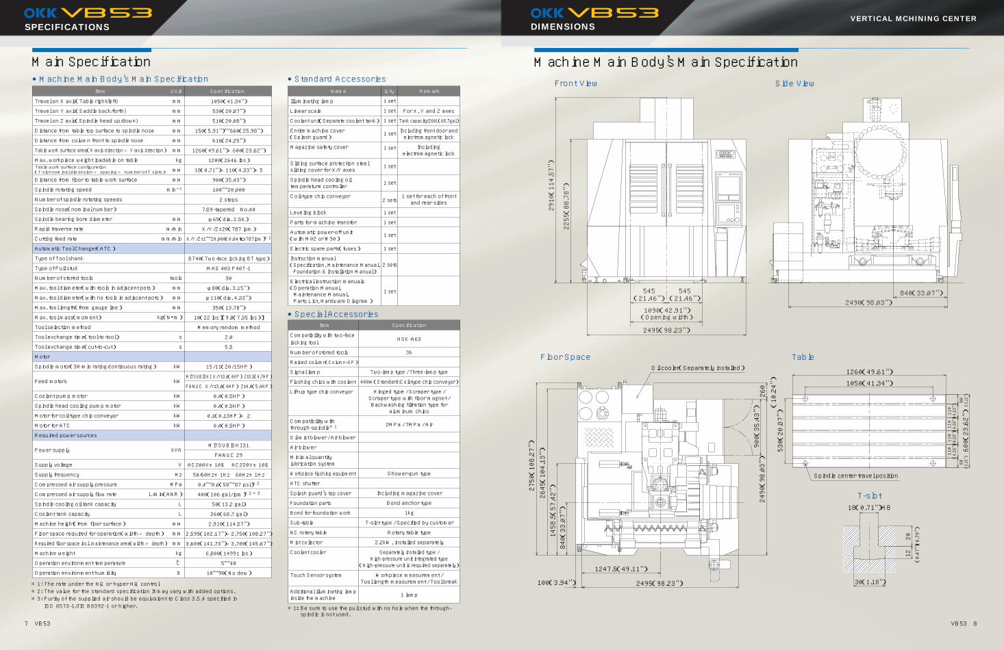
Main Specification Machine Main Body’s Main Specification
Floor Space Table
Front View Side View
T-slot
mm
mm
mm
mm
mm
mm
kg
mm
mm
min-1
mm
m/min
mm/min
tools
mm
mm
mm
kg(N・m)
s
s
kW
kW
kW
kW
kW
kW
kVA
V
Hz
MPa
L/min(ANR)
L
L
mm
mm
mm
kg
℃
%
1050(41.34")
530(20.87")
510(20.08")
150(5.91")~660(25.98")
616(24.25")
1260(49.61")×600(23.62")
1200(2646 lbs)
18(0.71")×110(4.33")×5
900(35.43")
100~20,000
2 steps
7/24-tapered No.40
φ65(dia. 2.56)
X/Y/Z:20(787 ipm)
X/Y/Z:1~20,000(0.04 to 787ipm)※1
BT40(Two-face locking BT type)
MAS 403 P40T-1
30
φ80(dia. 3.15")
φ110(dia. 4.33")
350(13.78")
10(22 lbs)[9.8(7.35 lbs)]
Memory random method
2.0
5.5
15/11(20/15HP)
MITSUBISHI X/Y:3.0(4HP) Z:3.5(4.7HP)
FANUC X/Y:3.0(4HP) Z:4.0(5.4HP)
0.4(0.5HP)
0.4(0.5HP)
0.1(0.13HP)× 2
0.4(0.5HP)
MITSUBISHI 31
FANUC 29
AC200V±10% AC220V±10%
50/60Hz±1Hz 60Hz±1Hz
0.4~0.6(58~87 psi)※2
400(106 gal / ipm)※2 ※3
50(13.2 gal)
260(68.7 gal)
2,910(114.57")
2,595(102.17")×2,750(108.27")
3,600(141.73")×3,700(145.67")
6,800(14991 lbs)
5~40
10~90(No dew)
Item Unit Specification
Travel on X axis(Table right/left)
Travel on Y axis(Saddle back/forth)
Travel on Z axis(Spindle head up/down)
Distance from table top surface to spindle nose
Distance from column front to spindle nose
Table work surface area(X-axis direction × Y-axis direction)
Max. workpiece weight loadable on table
Distance from floor to table work surface
Spindle rotating speed
Number of spindle rotating speeds
Spindle nose(nominal number)
Spindle bearing bore diameter
Rapid traverse rate
Cutting feed rate
Automatic Tool Changer(ATC)
Type of Tool shank
Type of Pull stud
Number of stored tools
Max. tool diameter(with tools in adjacent pots)
Max. tool diameter(with no tools in adjacent pots)
Max. tool length(from gauge line)
Max. tool mass(moment)
Tool selection method
Tool exchange time(tool-to-tool)
Tool exchange time(cut-to-cut)
Motor
Spindle motor(30-min rating/continuous rating)
Feed motors
Coolant pump motor
Spindle head cooling pump motor
Motor for coil-type chip conveyor
Motor for ATC
Required power sources
Power supply
Supply voltage
Supply frequency
Compressed air supply pressure
Compressed air supply flow rate
Spindle cooling oil tank capacity
Coolant tank capacity
Machine height(from floor surface)
Floor space required for operation(width × depth)
Required floor space incl. maintenance area(width × depth)
Machine weight
Operation environment temperature
Operation environment humidity
●Special Accessories
※1: The rate under the HQ or hyper HQ control ※2: The value for the standard specification It may vary with added options. ※3: Purity of the supplied air should be equivalent to Class 3.5.4 specified in ISO 8573-1/JIS B8392-1 or higher. ※1: Be sure to use the pull stud with no hole when the through-
spindle is not used.
●Standard Accessories●Machine Main Body’s Main Specification
1 set
1 set
1 set
1 set
1 set
Name
Item Specification
Qty Remark
Illuminating lamp
Linear scale
Coolant unit(Separate coolant tank)
Entire machine cover (Splash guard)
Magazine safety cover
Sliding surface protection steel sliding cover for X/Y axes
Spindle head cooling oil temperature controller
Coil-type chip conveyor
Leveling block
Parts for machine transfer
Automatic power-off unit (with M02 or M30)
Electric spare parts(fuses)
Compatibility with two-face locking tool
Number of stored tools
Raised column(Column-UP)
Signal lamp
Flushing chips with coolant
Lift-up type chip conveyor
Compatibility with through-spindle※1
Oil-mist blower / Air blower
Air blower
Minimal quantity lubrication system
Workpiece flushing equipment
ATC shutter
Splash guard’s top cover
Foundation parts
Bond for foundation work
Sub-table
NC rotary table
Mist collector
Coolant cooler
Touch Sensor system
Additional illuminating lamp inside the machine
36
Two-lamp type / Three-lamp type
400W(Standard:Coil-type chip conveyor)
Including magazine cover
Bond anchor type
1kg
T-slot type / Specified by customer
Rotary table type
2.2kW, installed separately
For X, Y and Z axes
Tank capacity:260L(68.7gal)
Including front door and electromagnetic lock
Including electromagnetic lock
1 set for each of front and rear sides
Hinged type / Scraper type / Scraper type with floor magnet / Backwashing filtration type for
aluminum chips
Electrical instruction manuals (Operation Manual, Maintenance Manual, Parts List, Hardware Diagram)
Instruction manual (Specification, Maintenance Manual, Foundation & Installation Manual)
1 set
1 set
1 set
1 set
1 set
1 set
1 set
2 sets
2 sets
Separately installed type / High-pressure unit integrated type
(High-pressure unit is required separately)
Workpiece measurement / Tool length measurement / Tool break
HSK-A63
2MPa / 7MPa / Air
Shower-gun type
1 lamp
Table work surface configuration (T-slot nominal dimension × spacing × number of T slots)
7 VB53 VB53 8
VB53_E.Q 12.3.22 2:59 PM ページ 9
9 VB53 VB53 10
N730
CONTROLLER
F31i-A
VERTICAL MCHINING CENTER
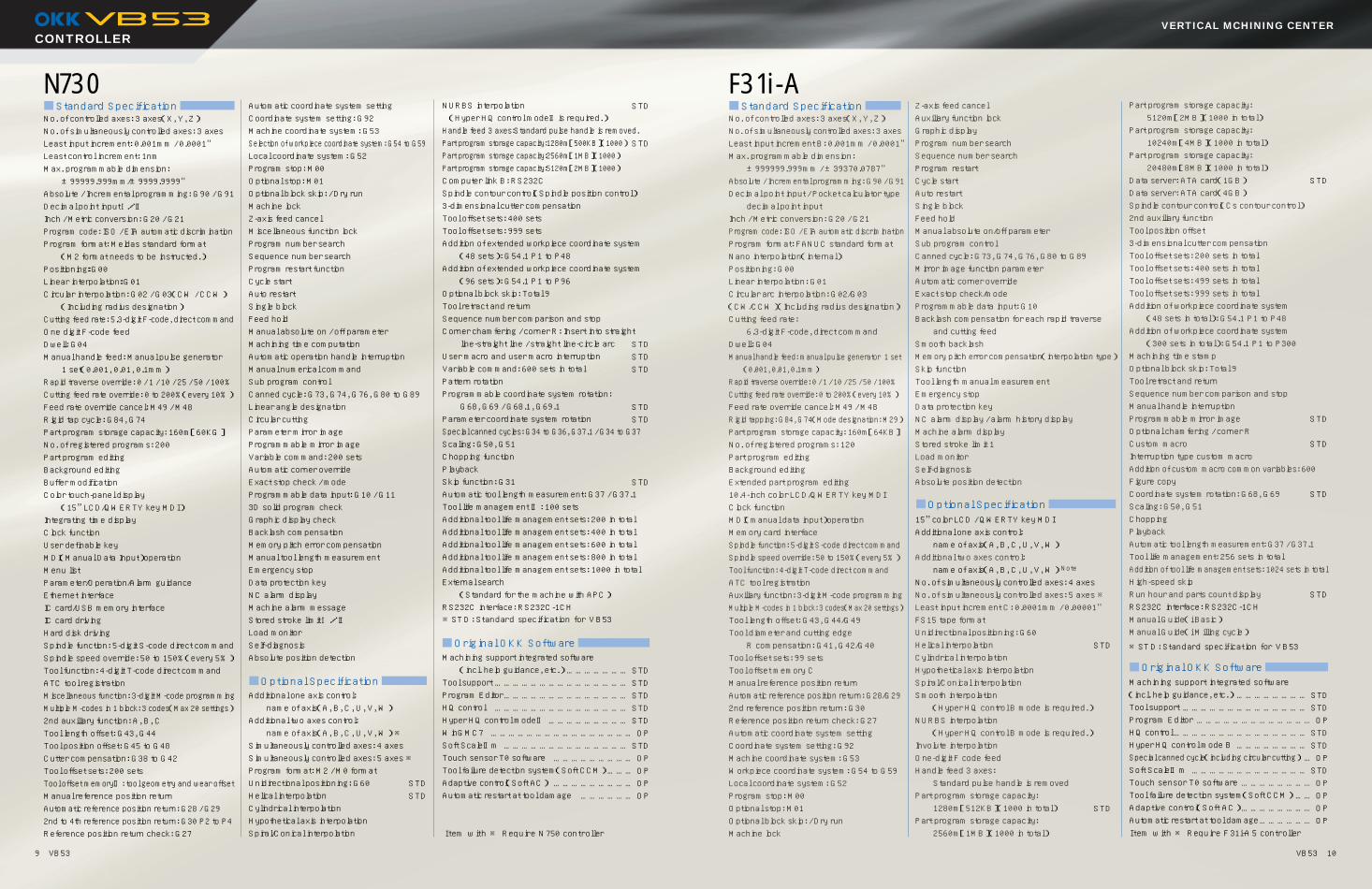
No. of controlled axes: 3 axes(X, Y, Z) No. of simultaneously controlled axes: 3 axes Least input increment: 0.001mm / 0.0001" Least control increment: 1nm Max. programmable dimension: ±99999.999mm/±9999.9999" Absolute / Incremental programming: G90 / G91 Decimal point inputⅠ/Ⅱ Inch / Metric conversion: G20 / G21 Program code: ISO / EIA automatic discrimination Program format: Meldas standard format (M2 format needs to be instructed.) Positioning:G00 Linear interpolation:G01 Circular interpolation: G02 / G03(CW / CCW) (Including radius designation) Cutting feed rate: 5.3-digit F-code, direct command One digit F-code feed Dwell: G04 Manual handle feed: Manual pulse generator 1 set(0.001, 0.01, 0.1mm) Rapid traverse override: 0 / 1 / 10 / 25 / 50 / 100% Cutting feed rate override: 0 to 200%(every 10%) Feed rate override cancel: M49 / M48 Rigid tap cycle: G84, G74 Part program storage capacity: 160m[60KG] No. of registered programs: 200 Part program editing Background editing Buffer modification Color touch-panel display (15”LCD/QWERTY key MDI) Integrating time display Clock function User definable key MDI(Manual Data Input)operation Menu list Parameter/Operation/Alarm guidance Ethernet interface IC card/USB memory interface IC card driving Hard disk driving Spindle function: 5-digit S-code direct command Spindle speed override: 50 to 150%(every 5%) Tool function: 4-digit T-code direct command ATC tool registration Miscellaneous function: 3-digit M-code programming Multiple M-codes in 1 block: 3 codes(Max 20 settings)2nd auxiliary function: A, B, C Tool length offset: G43, G44 Tool position offset: G45 to G48 Cutter compensation: G38 to G42 Tool offset sets: 200 sets Tool offset memoryⅡ: tool geometry and wear offset Manual reference position return Automatic reference position return: G28 / G29 2nd to 4th reference position return: G30 P2 to P4 Reference position return check: G27
Automatic coordinate system setting Coordinate system setting: G92 Machine coordinate system: G53 Selection of workpiece coordinate system: G54 to G59 Local coordinate system: G52 Program stop: M00 Optional stop: M01 Optional block skip: / Dry run Machine lock Z-axis feed cancel Miscellaneous function lock Program number search Sequence number search Program restart function Cycle start Auto restart Single block Feed hold Manual absolute on / off parameter Machining time computation Automatic operation handle interruption Manual numerical command Sub program control Canned cycle: G73, G74, G76, G80 to G89 Linear angle designation Circular cutting Parameter mirror image Programmable mirror image Variable command: 200 sets Automatic corner override Exact stop check / mode Programmable data input: G10 / G11 3D solid program check Graphic display check Backlash compensation Memory pitch error compensation Manual tool length measurement Emergency stop Data protection key NC alarm display Machine alarm message Stored stroke limitⅠ/Ⅱ Load monitor Self-diagnosis Absolute position detection Additional one axis control: name of axis(A, B, C, U, V, W) Additional two axes control: name of axis(A, B, C, U, V, W) ※ Simultaneously controlled axes: 4 axes Simultaneously controlled axes: 5 axes ※ Program format: M2 / M0 format Unidirectional positioning: G60 Helical interpolation Cylindrical interpolation Hypothetical axis interpolation Spiral/Conical interpolation
NURBS interpolation (Hyper HQ control modeⅡis required.) Handle feed 3 axes:Standard pulse handle is removed. Part program storage capacity:1280m[500KB](1000) Part program storage capacity:2560m[1MB](1000) Part program storage capacity:5120m[2MB](1000) Computer link B: RS232C Spindle contour control(Spindle position control) 3-dimensional cutter compensation Tool offset sets: 400 sets Tool offset sets: 999 sets Addition of extended workpiece coordinate system (48 sets): G54.1 P1 to P48 Addition of extended workpiece coordinate system (96 sets): G54.1 P1 to P96 Optional block skip: Total 9 Tool retract and return Sequence number comparison and stop Corner chamfering / corner R: Insert into straight line-straight line / straight line-circle arc User macro and user macro interruption Variable command: 600 sets in total Pattern rotation Programmable coordinate system rotation: G68, G69 / G68.1, G69.1 Parameter coordinate system rotation Special canned cycles: G34 to G36, G37.1 / G34 to G37 Scaling: G50, G51 Chopping function Playback Skip function: G31 Automatic tool length measurement: G37 / G37.1 Tool life management Ⅱ: 100 sets Additional tool life management sets: 200 in total Additional tool life management sets: 400 in total Additional tool life management sets: 600 in total Additional tool life management sets: 800 in total Additional tool life management sets: 1000 in total External search (Standard for the machine with APC) RS232C interface: RS232C-1CH Machining support integrated software (incl. help guidance, etc.) Tool support Program Editor HQ control Hyper HQ control modeⅡ WinGMC7 Soft ScaleⅡm Touch sensor T0 software Tool failure detection system(Soft CCM) Adaptive control(Soft AC) Automatic restart at tool damage
No. of controlled axes: 3 axes(X, Y, Z) No. of simultaneously controlled axes: 3 axes Least input increment B: 0.001mm / 0.0001" Max. programmable dimension: ±999999.999mm / ±39370.0787" Absolute / Incremental programming: G90 / G91 Decimal point input / Pocket calculator type decimal point input Inch / Metric conversion: G20 / G21 Program code: ISO / EIA automatic discrimination Program format: FANUC standard format Nano interpolation(internal) Positioning: G00 Linear interpolation: G01 Circular arc interpolation: G02/G03 (CW/CCW)(Including radius designation) Cutting feed rate: 6.3-digit F-code, direct command Dwell: G04 Manual handle feed: manual pulse generator 1 set (0.001, 0.01, 0.1mm) Rapid traverse override: 0 / 1 / 10 / 25 / 50 / 100% Cutting feed rate override: 0 to 200%(every 10%) Feed rate override cancel: M49 / M48 Rigid tapping: G84, G74(Mode designation: M29) Part program storage capacity: 160m[64KB] No. of registered programs: 120 Part program editing Background editing Extended part program editing 10.4-inch color LCD/QWERTY key MDI Clock function MDI(manual data input)operation Memory card interface Spindle function: 5-digit S-code direct command Spindle speed override: 50 to 150%(every 5%) Tool function: 4-digit T-code direct command ATC tool registration Auxiliary function: 3-digit M-code programming Multiple M-codes in 1 block: 3 codes(Max 20 settings) Tool length offset: G43, G44/G49 Tool diameter and cutting edge R compensation: G41, G42/G40 Tool offset sets: 99 sets Tool offset memory C Manual reference position return Automatic reference position return: G28/G29 2nd reference position return: G30 Reference position return check: G27 Automatic coordinate system setting Coordinate system setting: G92 Machine coordinate system: G53 Workpiece coordinate system: G54 to G59 Local coordinate system: G52 Program stop: M00 Optional stop: M01 Optional block skip: / Dry run Machine lock
Z-axis feed cancel Auxiliary function lock Graphic display Program number search Sequence number search Program restart Cycle start Auto restart Single block Feed hold Manual absolute on/off parameter Sub program control Canned cycle: G73, G74, G76, G80 to G89 Mirror image function parameter Automatic corner override Exact stop check/mode Programmable data input: G10 Backlash compensation for each rapid traverse and cutting feed Smooth backlash Memory pitch error compensation(interpolation type) Skip function Tool length manual measurement Emergency stop Data protection key NC alarm display / alarm history display Machine alarm display Stored stroke limit 1 Load monitor Self-diagnosis Absolute position detection 15” color LCD / QWERTY key MDI Additional one axis control: name of axis(A, B, C, U, V, W) Additional two axes control: name of axis(A, B, C, U, V, W) Note No. of simultaneously controlled axes: 4 axes No. of simultaneously controlled axes: 5 axes ※ Least input increment C: 0.0001mm / 0.00001" FS15 tape format Unidirectional positioning: G60 Helical interpolation Cylindrical interpolation Hypothetical axis interpolation Spiral/Conical interpolation Smooth interpolation (Hyper HQ control B mode is required.) NURBS interpolation (Hyper HQ control B mode is required.) Involute interpolation One-digit F code feed Handle feed 3 axes: Standard pulse handle is removed Part program storage capacity: 1280m[512KB](1000 in total) Part program storage capacity: 2560m[1MB](1000 in total)
Part program storage capacity: 5120m[2MB](1000 in total) Part program storage capacity: 10240m[4MB](1000 in total) Part program storage capacity: 20480m[8MB](1000 in total) Data server: ATA card(1GB) Data server: ATA card(4GB) Spindle contour control(Cs contour control) 2nd auxiliary function Tool position offset 3-dimensional cutter compensation Tool offset sets: 200 sets in total Tool offset sets: 400 sets in total Tool offset sets: 499 sets in total Tool offset sets: 999 sets in total Addition of workpiece coordinate system (48 sets in total): G54.1 P1 to P48 Addition of workpiece coordinate system (300 sets in total): G54.1 P1 to P300 Machining time stamp Optional block skip: Total 9 Tool retract and return Sequence number comparison and stop Manual handle interruption Programmable mirror image Optional chamfering / corner R Custom macro Interruption type custom macro Addition of custom macro common variables: 600 Figure copy Coordinate system rotation: G68, G69 Scaling: G50, G51 Chopping Playback Automatic tool length measurement: G37 / G37.1 Tool life management: 256 sets in total Addition of tool life management sets: 1024 sets in total High-speed skip Run hour and parts count display RS232C interface: RS232C-1CH Manual Guide(i Basic) Manual Guide(i Milling cycle) Machining support integrated software (incl. help guidance, etc.) Tool support Program Editor HQ control Hyper HQ control mode B Special canned cycle(including circular cutting) Soft ScaleⅡm Touch sensor T0 software Tool failure detection system(Soft CCM) Adaptive control(Soft AC) Automatic restart at tool damageItem with ※ Require F31i-A5 controllerItem with ※ Require N750 controller
STD STD
STD STD
STD STD STD STD STD
Optional Specification
Original OKK Software
Optional Specification
Original OKK Software
Standard Specification Standard Specification
※STD: Standard specification for VB53
※STD: Standard specification for VB53
………………… STD ……………………………………… STD …………………………………… STD
……………………………………… STD ……………………… STD
………………………………………… OP …………………………………… STD
……………………… OP ……… OP
……………………… OP ……………… OP
STD STD STD STD STD STD STD STD
…………………… STD …………………………………… STD ………………………………… OP
……………………………………… STD …………………… STD
… OP ………………………………… STD
…………………… OP …… OP
…………………… OP ……………… OP
VB53_E.Q 12.3.22 2:59 PM ページ 11
12.03.2M(H)
S-Plant W-PlantTechnical Center
INAGAWA PLANT:8-10, KITA-ITAMI, ITAMI, HYOGO 664-0831 JAPAN�TEL:(81)72-782-5121�FAX:(81)72-772-5156�E-mail:[email protected]
OKK USA CORPORATION100 REGENCY DRIVE, GLENDALE HEIGHTS, IL 60139 USA�TEL:(1)630-924-9000�FAX:(1)630-924-9010�http://www.okkcorp.com�E-mail:[email protected]
OKK USA WESTERN REGIONAL OFFICE(LA)17971 SKY PARK CIRCLE, SUITE D, IRVINE CA 92614 USA�TEL:(1)949-851-6800�FAX:(1)949-851-6888
OKK CANADA OFFICE(CANADA)7449 AUBURN ROAD, UNIT 1B HORNBY, ONTARIO, LOP 1EO, CANADA�TEL:(1)905-639-9784�FAX:(1)905-639-9503
OKK EUROPE GmbHHANSEMANNSTR, 33 41468 NEUSS GERMANY�TEL:(49)2131-29868-0�FAX:(49)2131-29868-41�http://www.okkeurope.com�E-mail:[email protected]
OKK(SHANGHAI) CO., LTD.ROOM C303, BUILDING 8, No.1221 HAMI ROAD CHANGNING�DISTRICT SHANGHAI P.C200335 CHINA�TEL:(86)21-62700930�FAX:(86)21-62700931�http://www.okk.com.cn�E-mail:[email protected]
OKK(SHANGHAI) CO., LTD. BEIJING BRANCHROOM 1905, EAST OCEAN CENTER, No.24A JIAN GUO MEN STREET �CHAO YANG DISTRICT, BEIJING, 100004 CHINA�TEL:(86)10-6515-0502/0702�FAX:(86)10-6515-5087�E-mail:[email protected]
OKK CORPORATION SEOUL BRANCH1203, E & C DREAM TOWER 8, 327-27, GASAN-DONG,�GEUMCHEON-GU, SEOUL, 153-023 KOREA�TEL:(82)2-855-0416�FAX:(82)2-855-0426
PT. OKK INDONESIAWISMA NUSANTARA BUILDING 12 FLOOR,�JL.M.H.THAMRIN No.59, JAKARTA. 10350 INDONESIA�TEL:(62)021-390-2563 / 2564�FAX:(62)021-390-2565
The export of this product is subject to an authorization from�the government of the exporting country.�Check with the government agency for authorization.
NOTE :�OKK reserves the right to change the information contained in�this brochure wihtout notice.�OKK is not responsible to make changes to previously sold�machines or accessories.
8-10, KITA-ITAMI, ITAMIHYOGO, JAPANOverseas Sales DepartmentTEL:(81)72-771-1112/1143FAX:(81)72-772-7592http://www.okk.co.jpE-mail:[email protected]
Technical center is for test cutting, demonstration and training.�S-plant is for machining and assembly of spindles and tables.�W-plant is for final assembly of large sized machining centers.�All are located at Inagawa, Itami city, Hyogo, Japan
OKK A DIVERSIFIED MANUFACTURER OF�MACHINE TOOLS�Specializes In:Machining centers�Graphite cutting machining centers�Grinding centers�CNC Milling machines�Conventional milling machines�Total die and mold making systems�Flexible manufacturing cells and systems
Other Products Include:�Textile Machinery�Water Maters
THAI OKK MACHINERY CO., LTD.�KUMTHORN HOLDING BUILDING 2ND FLOOR 897-897/1 RAMA III�ROAD BANGPONGPANG, YANNAWA, BANGKOK 10120 THAILAND�TEL:(66)2-683-2160-2�FAX:(66)2-683-2163
Printed with eco-friendly soy ink on recycled paper.
VB53_E.Q 12.3.22 2:59 PM ページ 1