Embed Size (px)
Citation preview

H S C P
ITA
LIA
NO
EN
GL
ISH
ISTRUZIONI D’USO PER L’UTENTEUSER’S OPERATING INSTRUCTION
2
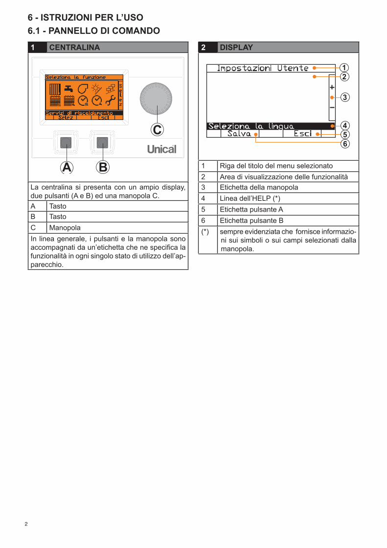
6 - ISTRUZIONI PER L’USO6.1 - PANNELLO DI COMANDO
2 DISPLAY
1 Riga del titolo del menu selezionato2 Area di visualizzazione delle funzionalità3 Etichetta della manopola4 Linea dell’HELP (*) 5 Etichetta pulsante A6 Etichetta pulsante B(*) sempre evidenziata che fornisce informazio-
ni sui simboli o sui campi selezionati dalla manopola.
1 CENTRALINA
La centralina si presenta con un ampio display, due pulsanti (A e B) ed una manopola C.A Tasto B Tasto C ManopolaIn linea generale, i pulsanti e la manopola sono accompagnati da un’etichetta che ne specifica la funzionalità in ogni singolo stato di utilizzo dell’ap-parecchio.
3
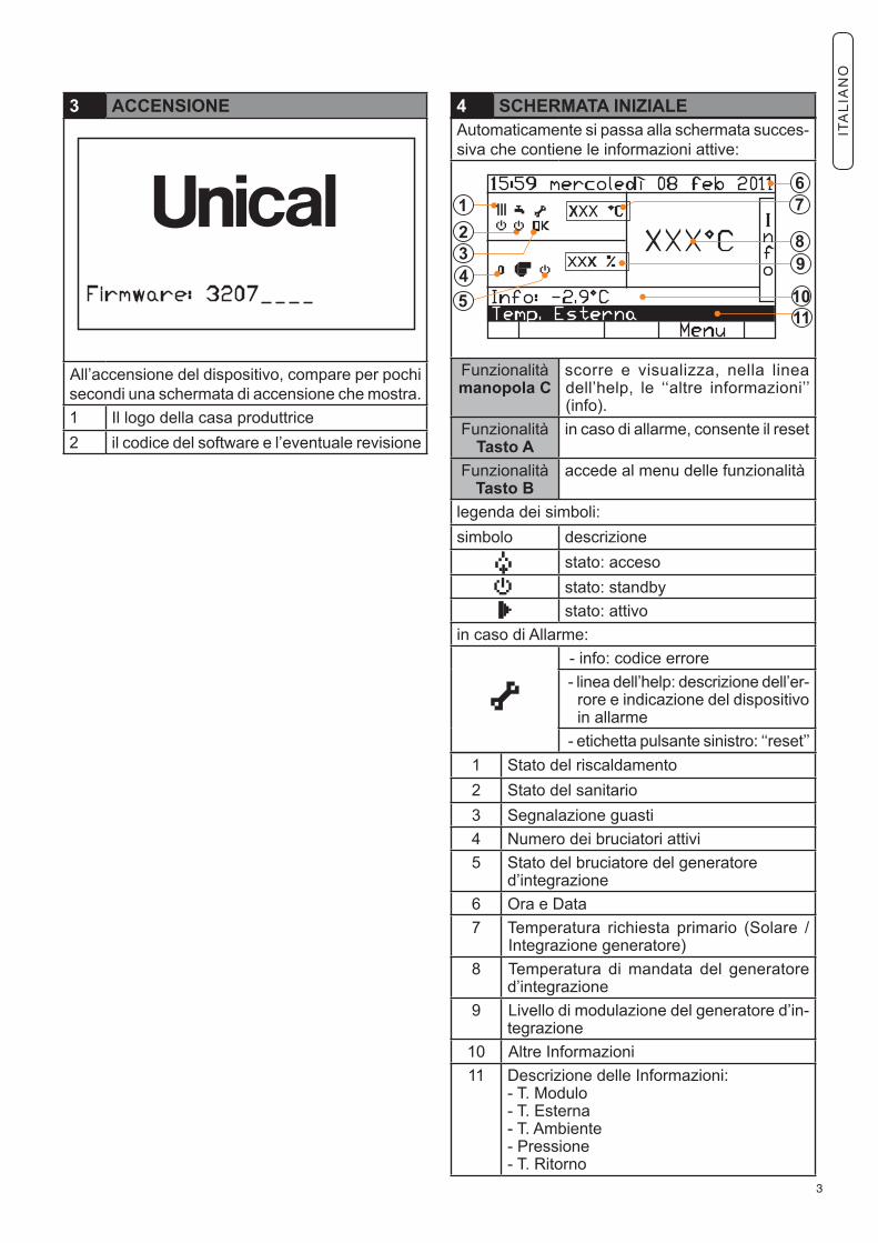
3 ACCENSIONE
All’accensione del dispositivo, compare per pochi secondi una schermata di accensione che mostra. 1 Il logo della casa produttrice2 il codice del software e l’eventuale revisione
4 SCHERMATA INIZIALEAutomaticamente si passa alla schermata succes-siva che contiene le informazioni attive:
Funzionalitàmanopola C
scorre e visualizza, nella linea dell’help, le ‘‘altre informazioni’’ (info).
FunzionalitàTasto A
in caso di allarme, consente il reset
FunzionalitàTasto B
accede al menu delle funzionalità
legenda dei simboli:simbolo descrizione stato: acceso stato: standby
stato: attivo in caso di Allarme:
- info: codice errore - linea dell’help: descrizione dell’er-
rore e indicazione del dispositivo in allarme
- etichetta pulsante sinistro: ‘‘reset’’1 Stato del riscaldamento2 Stato del sanitario3 Segnalazione guasti 4 Numero dei bruciatori attivi 5 Stato del bruciatore del generatore
d’integrazione 6 Ora e Data 7 Temperatura richiesta primario (Solare /
Integrazione generatore)8 Temperatura di mandata del generatore
d’integrazione9 Livello di modulazione del generatore d’in-
tegrazione10 Altre Informazioni11 Descrizione delle Informazioni:
- T. Modulo- T. Esterna- T. Ambiente- Pressione- T. Ritorno
ITA
LIA
NO
4
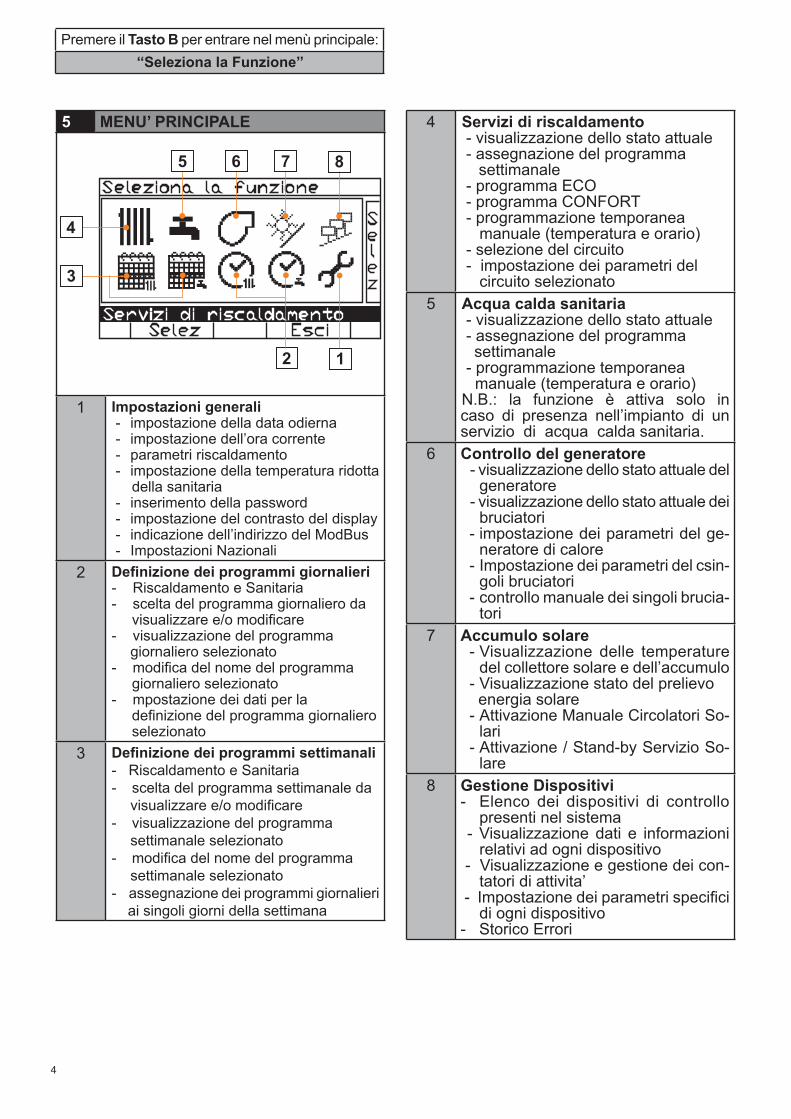
5 MENU’ PRINCIPALE
1 Impostazioni generali - impostazione della data odierna - impostazione dell’ora corrente - parametri riscaldamento - impostazione della temperatura ridotta della sanitaria - inserimento della password - impostazione del contrasto del display - indicazione dell’indirizzo del ModBus - Impostazioni Nazionali
2 Definizione dei programmi giornalieri - Riscaldamento e Sanitaria- scelta del programma giornaliero da visualizzare e/o modificare- visualizzazione del programma giornaliero selezionato- modifica del nome del programma giornaliero selezionato- mpostazione dei dati per la definizione del programma giornaliero selezionato
3 Definizione dei programmi settimanali - Riscaldamento e Sanitaria- scelta del programma settimanale da visualizzare e/o modificare- visualizzazione del programma settimanale selezionato- modifica del nome del programma settimanale selezionato- assegnazione dei programmi giornalieri ai singoli giorni della settimana
Premere il Tasto B per entrare nel menù principale: ‘‘Seleziona la Funzione’’
4 Servizi di riscaldamento - visualizzazione dello stato attuale - assegnazione del programma settimanale - programma ECO - programma CONFORT - programmazione temporanea manuale (temperatura e orario) - selezione del circuito - impostazione dei parametri del circuito selezionato
5 Acqua calda sanitaria - visualizzazione dello stato attuale - assegnazione del programma settimanale - programmazione temporanea manuale (temperatura e orario)N.B.: la funzione è attiva solo in caso di presenza nell’impianto di un servizio di acqua calda sanitaria.
6 Controllo del generatore - visualizzazione dello stato attuale del generatore - visualizzazione dello stato attuale dei bruciatori - impostazione dei parametri del ge-
neratore di calore - Impostazione dei parametri del csin-
goli bruciatori - controllo manuale dei singoli brucia-
tori7 Accumulo solare
- Visualizzazione delle temperature del collettore solare e dell’accumulo
- Visualizzazione stato del prelievo energia solare - Attivazione Manuale Circolatori So-
lari - Attivazione / Stand-by Servizio So-
lare8 Gestione Dispositivi
- Elenco dei dispositivi di controllo presenti nel sistema
- Visualizzazione dati e informazioni relativi ad ogni dispositivo
- Visualizzazione e gestione dei con-tatori di attivita’
- Impostazione dei parametri specifici di ogni dispositivo
- Storico Errori
5
1 - IMPOSTAZIONI GENERALI 1/4
1 - IMPOSTAZIONI GENERALI 2/4
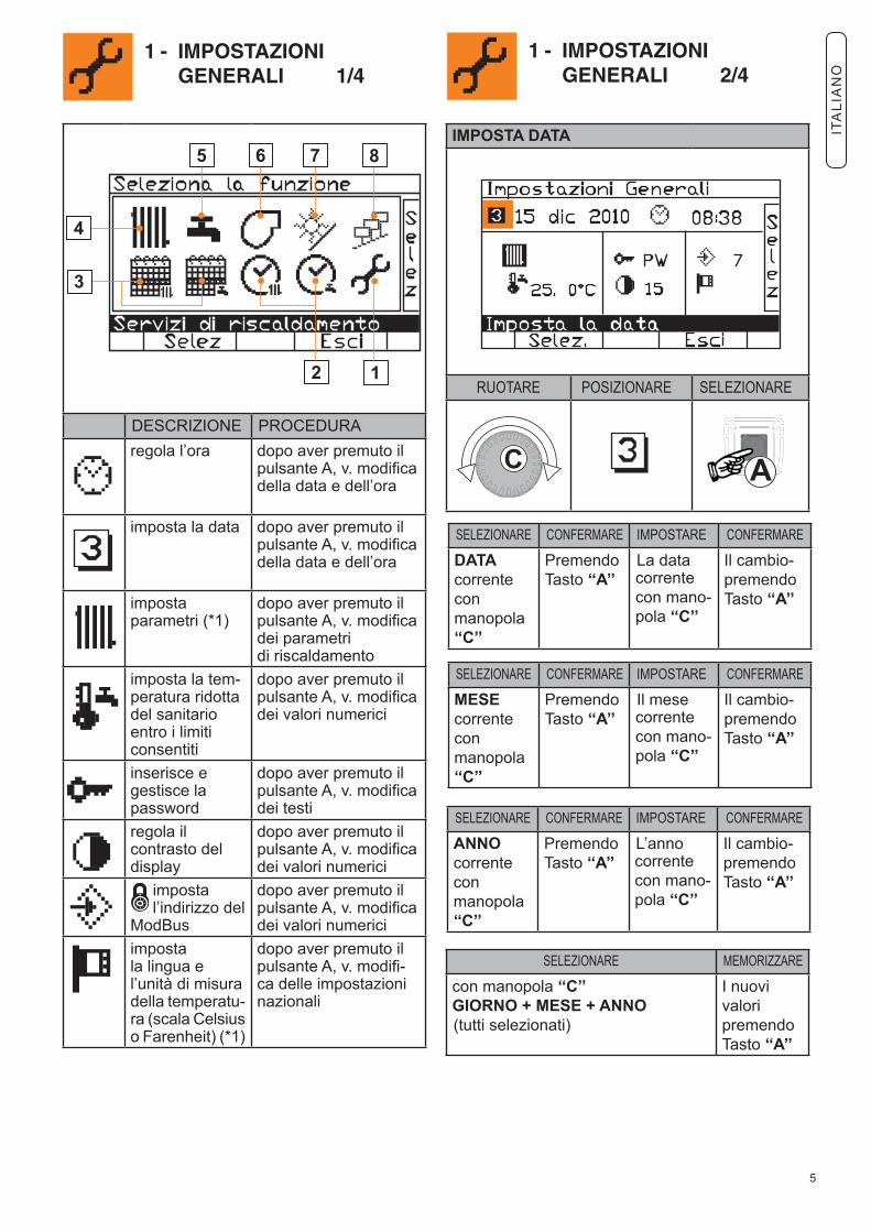
IMPOSTA DATA
RUOTARE POSIZIONARE SELEZIONARE
SELEZIONARE CONFERMARE IMPOSTARE CONFERMARE
MESE correntecon manopola‘‘C’’
PremendoTasto ‘‘A’’
Il mese corrente con mano-pola ‘‘C’’
Il cambio-premendoTasto ‘‘A’’
SELEZIONARE MEMORIZZARE
con manopola ‘‘C’’GIORNO + MESE + ANNO (tutti selezionati)
I nuovi valori premendoTasto ‘‘A’’
SELEZIONARE CONFERMARE IMPOSTARE CONFERMARE
ANNOcorrenteconmanopola‘‘C’’
PremendoTasto ‘‘A’’
L’anno corrente con mano-pola ‘‘C’’
Il cambio-premendoTasto ‘‘A’’
SELEZIONARE CONFERMARE IMPOSTARE CONFERMARE
DATA correntecon manopola‘‘C’’
PremendoTasto ‘‘A’’
La data corrente con mano-pola ‘‘C’’
Il cambio-premendoTasto ‘‘A’’
DESCRIZIONE PROCEDURAregola l’ora dopo aver premuto il
pulsante A, v. modifica della data e dell’ora
imposta la data dopo aver premuto il pulsante A, v. modifica della data e dell’ora
imposta parametri (*1)
dopo aver premuto il pulsante A, v. modifica dei parametri di riscaldamento
imposta la tem-peratura ridotta del sanitario entro i limiti consentiti
dopo aver premuto il pulsante A, v. modifica dei valori numerici
inserisce e gestisce la password
dopo aver premuto il pulsante A, v. modifica dei testi
regola il contrasto del display
dopo aver premuto il pulsante A, v. modifica dei valori numerici
imposta l’indirizzo del ModBus
dopo aver premuto il pulsante A, v. modifica dei valori numerici
impostala lingua el’unità di misuradella temperatu-ra (scala Celsius o Farenheit) (*1)
dopo aver premuto il pulsante A, v. modifi-ca delle impostazioni nazionali
ITA
LIA
NO
6
1 - IMPOSTAZIONI GENERALI 3/4
1 - IMPOSTAZIONI GENERALI 4/4
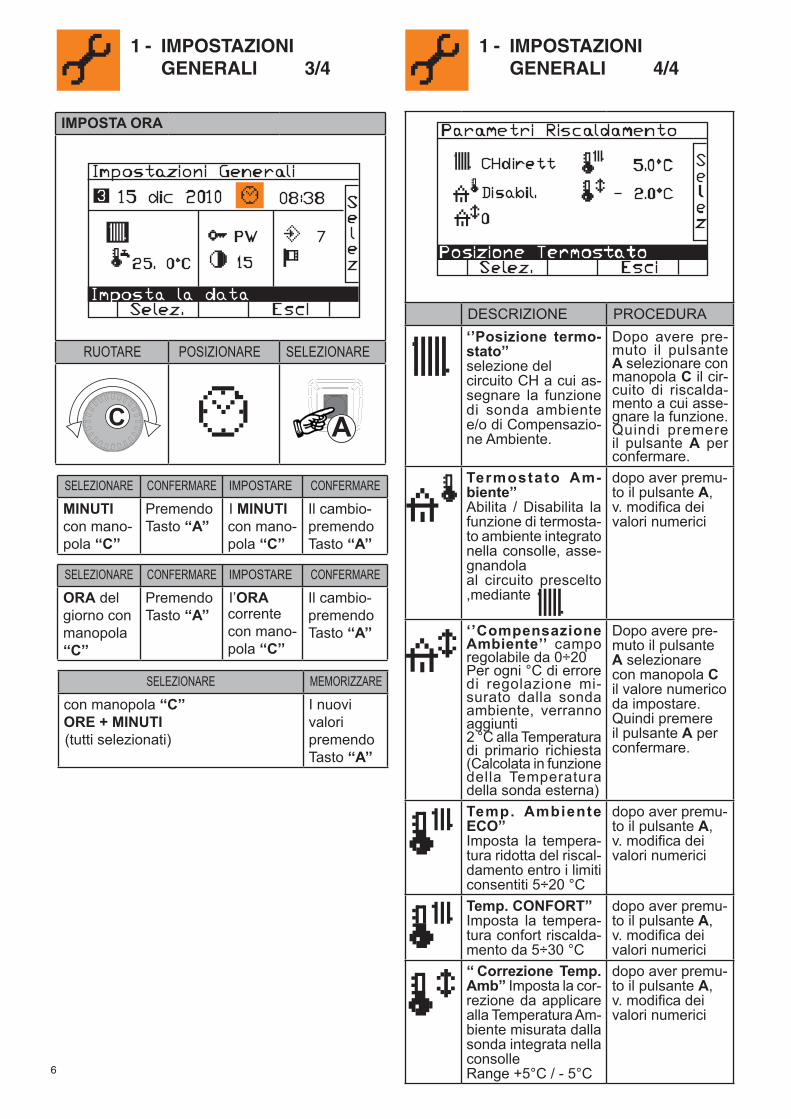
IMPOSTA ORA
RUOTARE POSIZIONARE SELEZIONARE
SELEZIONARE CONFERMARE IMPOSTARE CONFERMARE
ORA del giorno conmanopola‘‘C’’
PremendoTasto ‘‘A’’
I’ORA corrente con mano-pola ‘‘C’’
Il cambio-premendoTasto ‘‘A’’
SELEZIONARE MEMORIZZARE
con manopola ‘‘C’’ORE + MINUTI (tutti selezionati)
I nuovi valori premendoTasto ‘‘A’’
SELEZIONARE CONFERMARE IMPOSTARE CONFERMARE
MINUTIcon mano-pola ‘‘C’’
PremendoTasto ‘‘A’’
I MINUTI con mano-pola ‘‘C’’
Il cambio-premendoTasto ‘‘A’’
DESCRIZIONE PROCEDURA‘’Posizione termo-stato’’ selezione delcircuito CH a cui as-segnare la funzione di sonda ambiente e/o di Compensazio-ne Ambiente.
Dopo avere pre-muto il pulsante A selezionare con manopola C il cir-cuito di riscalda-mento a cui asse-gnare la funzione. Quindi premere il pulsante A per confermare.
Termostato Am-biente’’Abilita / Disabilita la funzione di termosta-to ambiente integrato nella consolle, asse-gnandolaal circuito prescelto ,mediante
dopo aver premu-to il pulsante A, v. modifica dei valori numerici
‘’Compensazione Ambiente’’ campo regolabile da 0÷20Per ogni °C di errore di regolazione mi-surato dalla sonda ambiente, verranno aggiunti2 °C alla Temperatura di primario richiesta (Calcolata in funzione della Temperatura della sonda esterna)
Dopo avere pre-muto il pulsante A selezionare con manopola C il valore numerico da impostare. Quindi premere il pulsante A per confermare.
Temp. Ambiente ECO’’Imposta la tempera-tura ridotta del riscal-damento entro i limiti consentiti 5÷20 °C
dopo aver premu-to il pulsante A, v. modifica dei valori numerici
Temp. CONFORT’’Imposta la tempera-tura confort riscalda-mento da 5÷30 °C
dopo aver premu-to il pulsante A, v. modifica dei valori numerici
‘‘ Correzione Temp. Amb’’ Imposta la cor-rezione da applicare alla Temperatura Am-biente misurata dalla sonda integrata nella consolleRange +5°C / - 5°C
dopo aver premu-to il pulsante A, v. modifica dei valori numerici
7
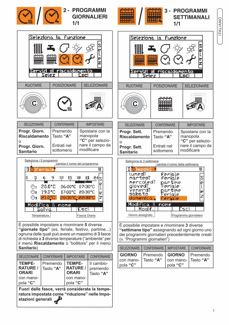
2 - PROGRAMMI GIORNALIERI 1/1
RUOTARE POSIZIONARE SELEZIONARE
È possibile impostare e rinominare 5 diverse “giornate tipo” (es. feriale, festivo, partime...) ognuna delle quali può avere un massimo di 3 fasce di richiesta a 3 diverse temperature (“ambiente” per il menù Riscaldamento o “bollitore” per il menù Sanitario)
SELEZIONARE CONFERMARE IMPOSTARE CONFERMARE
TEMPE-RATURE /ORARI con mano-pola ‘‘C’’
PremendoTasto ‘‘A’’
TEMPE-RATURE /ORARI con mano-pola ‘‘C’’
Il cambio-premendoTasto ‘‘A’’
Fuori dalle fasce, verrà considerata la tempe-ratura impostata come “riduzione” nelle Impo-stazioni generali
SELEZIONARE CONFERMARE IMPOSTARE
Progr. Giorn.RiscaldamentooProgr. Giorn.Sanitario
PremendoTasto ‘‘A’’
Entrati nel sottomenù
Spostarsi con la manopola‘‘C’’ per selezio-nare il campo da modificare
3 - PROGRAMMI SETTIMANALI 1/1
RUOTARE POSIZIONARE SELEZIONARE
È possibile impostare e rinominare 3 diverse “settimane tipo” assegnando ad ogni giorno uno dei programmi giornalieri precedentemente creati (v. “Programmi giornalieri”)
SELEZIONARE CONFERMARE IMPOSTARE CONFERMARE
GIORNO con mano-pola ‘‘C’’
PremendoTasto ‘‘A’’
GIORNO con mano-pola ‘‘C’’
PremendoTasto ‘‘A’’
SELEZIONARE CONFERMARE IMPOSTARE
Progr. Sett.RiscaldamentooProgr. Sett.Sanitario
PremendoTasto ‘‘A’’
Entrati nel sottomenù
Spostarsi con la manopola‘‘C’’ per selezio-nare il campo da modificare
ITA
LIA
NO
8
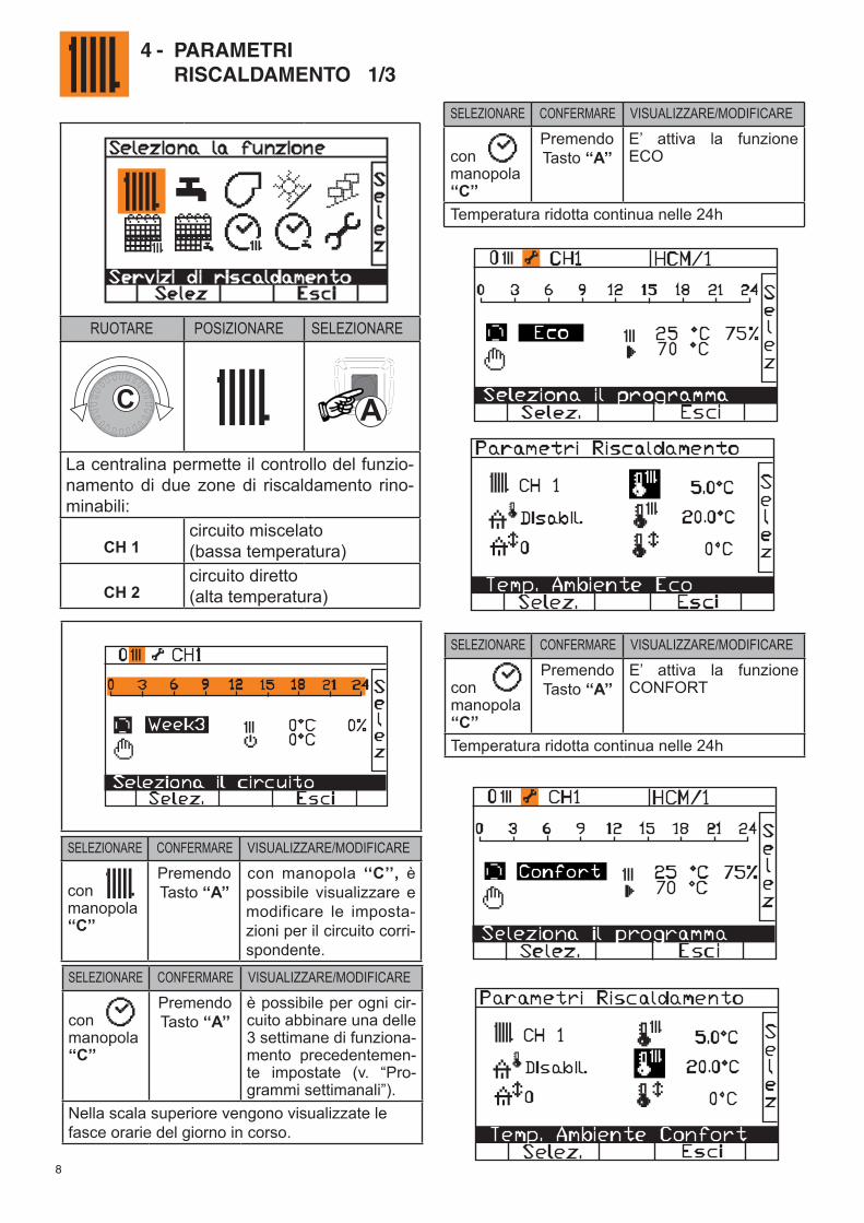
4 - PARAMETRI RISCALDAMENTO 1/3
RUOTARE POSIZIONARE SELEZIONARE
La centralina permette il controllo del funzio-namento di due zone di riscaldamento rino-minabili:
CH 1circuito miscelato (bassa temperatura)
CH 2circuito diretto(alta temperatura)
SELEZIONARE CONFERMARE VISUALIZZARE/MODIFICARE
conmanopola‘‘C’’
PremendoTasto ‘‘A’’
con manopola ‘‘C’’, è possibile visualizzare e modificare le imposta-zioni per il circuito corri-spondente.
SELEZIONARE CONFERMARE VISUALIZZARE/MODIFICARE
conmanopola‘‘C’’
PremendoTasto ‘‘A’’
è possibile per ogni cir-cuito abbinare una delle 3 settimane di funziona-mento precedentemen-te impostate (v. “Pro-grammi settimanali”).
Nella scala superiore vengono visualizzate le fasce orarie del giorno in corso.
SELEZIONARE CONFERMARE VISUALIZZARE/MODIFICARE
conmanopola‘‘C’’
PremendoTasto ‘‘A’’
E’ attiva la funzione ECO
Temperatura ridotta continua nelle 24h
SELEZIONARE CONFERMARE VISUALIZZARE/MODIFICARE
conmanopola‘‘C’’
PremendoTasto ‘‘A’’
E’ attiva la funzione CONFORT
Temperatura ridotta continua nelle 24h
9
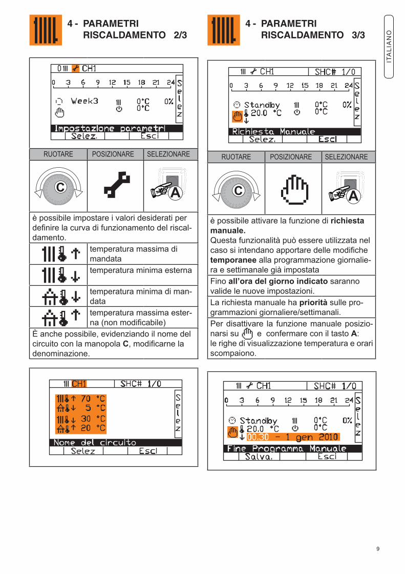
4 - PARAMETRI RISCALDAMENTO 2/3
4 - PARAMETRI RISCALDAMENTO 3/3
RUOTARE POSIZIONARE SELEZIONARE
è possibile impostare i valori desiderati per definire la curva di funzionamento del riscal-damento.
temperatura massima di mandata
temperatura minima esterna
temperatura minima di man-datatemperatura massima ester-na (non modificabile)
È anche possibile, evidenziando il nome del circuito con la manopola C, modificarne la denominazione.
RUOTARE POSIZIONARE SELEZIONARE
è possibile attivare la funzione di richiesta manuale.Questa funzionalità può essere utilizzata nel caso si intendano apportare delle modifiche temporanee alla programmazione giornalie-ra e settimanale già impostataFino all’ora del giorno indicato saranno valide le nuove impostazioni.La richiesta manuale ha priorità sulle pro-grammazioni giornaliere/settimanali.Per disattivare la funzione manuale posizio-narsi su e confermare con il tasto A: le righe di visualizzazione temperatura e orari scompaiono.
ITA
LIA
NO
10
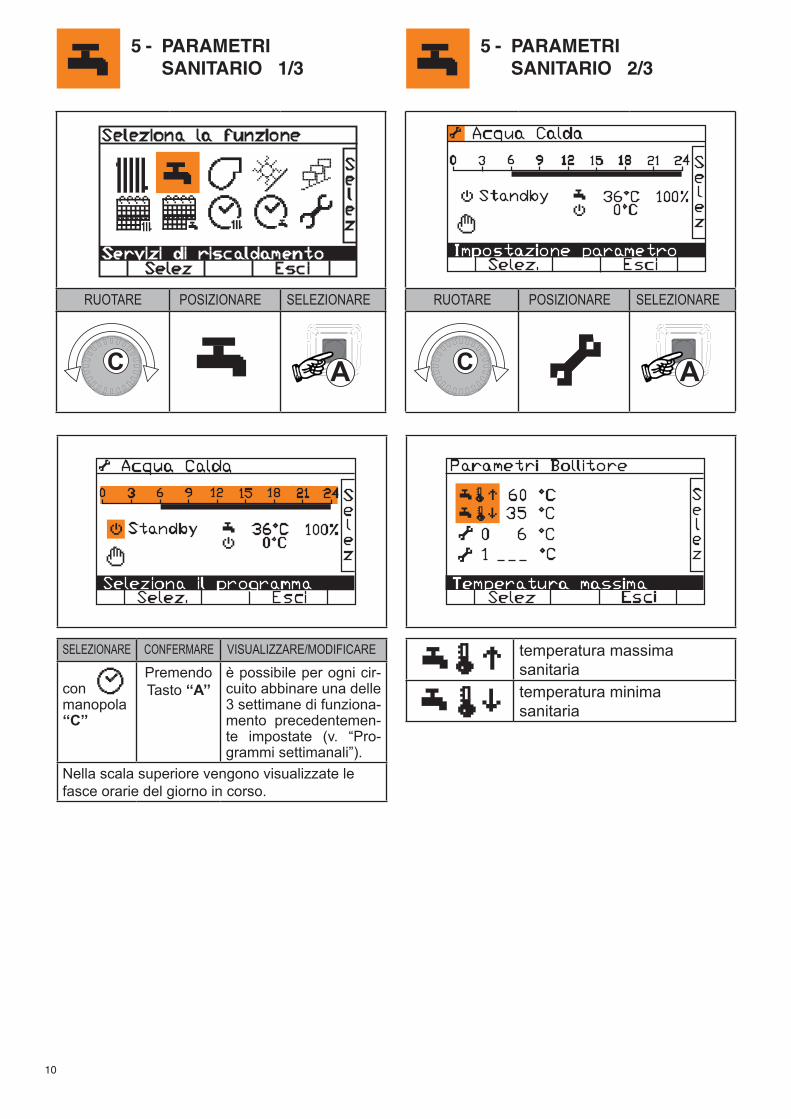
5 - PARAMETRI SANITARIO 1/3
5 - PARAMETRI SANITARIO 2/3
SELEZIONARE CONFERMARE VISUALIZZARE/MODIFICARE
conmanopola‘‘C’’
PremendoTasto ‘‘A’’
è possibile per ogni cir-cuito abbinare una delle 3 settimane di funziona-mento precedentemen-te impostate (v. “Pro-grammi settimanali”).
Nella scala superiore vengono visualizzate le fasce orarie del giorno in corso.
temperatura massima sanitariatemperatura minimasanitaria
RUOTARE POSIZIONARE SELEZIONARE
RUOTARE POSIZIONARE SELEZIONARE
11
5 - PARAMETRI SANITARIO 3/3
RUOTARE POSIZIONARE SELEZIONARE
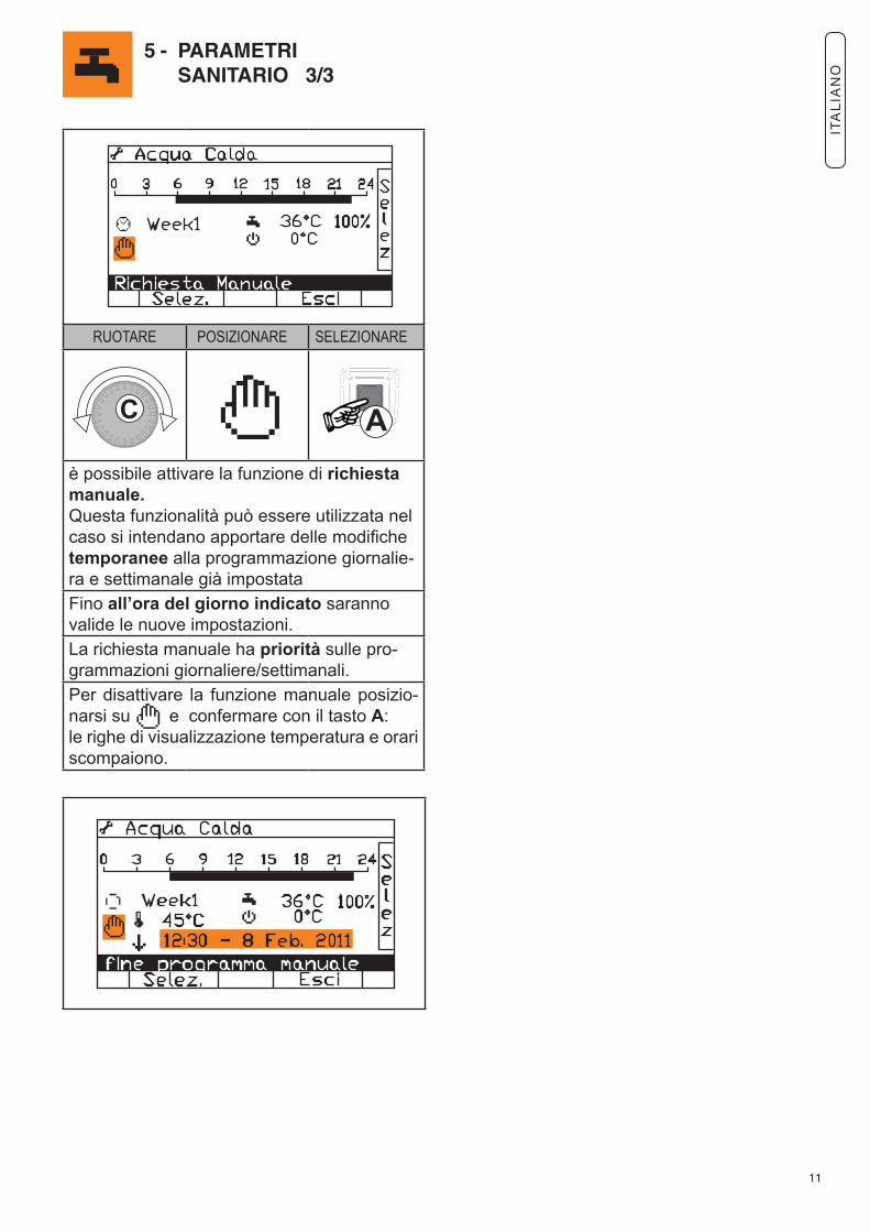
è possibile attivare la funzione di richiesta manuale.Questa funzionalità può essere utilizzata nel caso si intendano apportare delle modifiche temporanee alla programmazione giornalie-ra e settimanale già impostataFino all’ora del giorno indicato saranno valide le nuove impostazioni.La richiesta manuale ha priorità sulle pro-grammazioni giornaliere/settimanali.Per disattivare la funzione manuale posizio-narsi su e confermare con il tasto A: le righe di visualizzazione temperatura e orari scompaiono.
ITA
LIA
NO
12
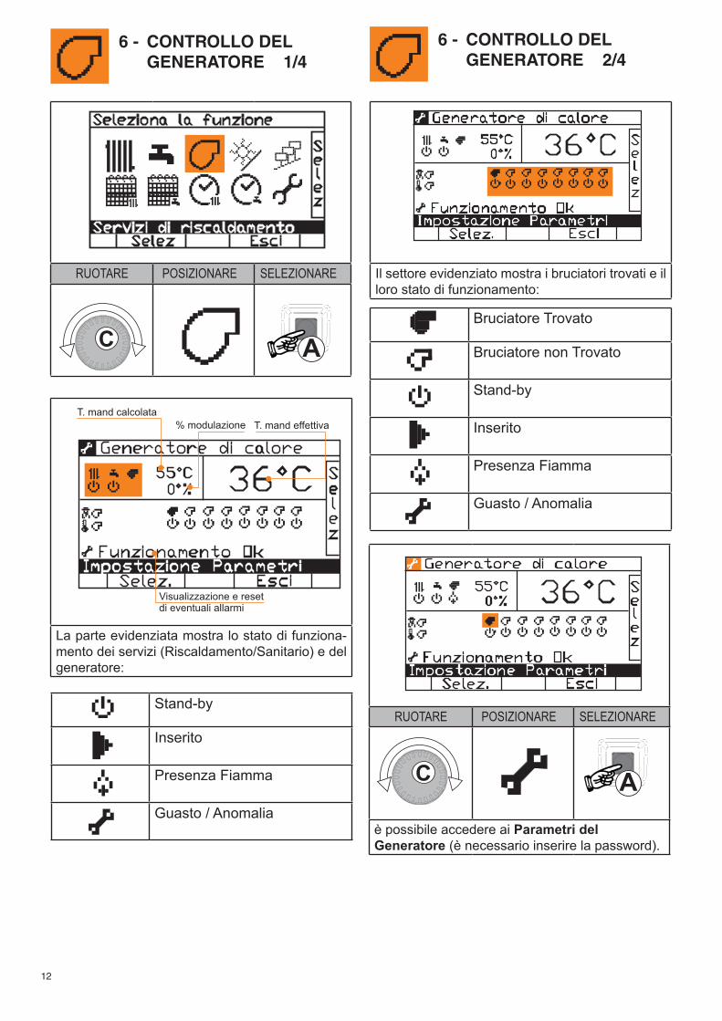
La parte evidenziata mostra lo stato di funziona-mento dei servizi (Riscaldamento/Sanitario) e del generatore:
Il settore evidenziato mostra i bruciatori trovati e il loro stato di funzionamento:
Stand-by
Inserito
Presenza Fiamma
Guasto / Anomalia
Bruciatore Trovato
Bruciatore non Trovato
Stand-by
Inserito
Presenza Fiamma
Guasto / Anomalia
RUOTARE POSIZIONARE SELEZIONARE
è possibile accedere ai Parametri delGeneratore (è necessario inserire la password).
6 - CONTROLLO DEL GENERATORE 1/4
6 - CONTROLLO DEL GENERATORE 2/4
RUOTARE POSIZIONARE SELEZIONARE
13
6 - CONTROLLO DEL GENERATORE 3/4
6 - CONTROLLO DEL GENERATORE 4/4
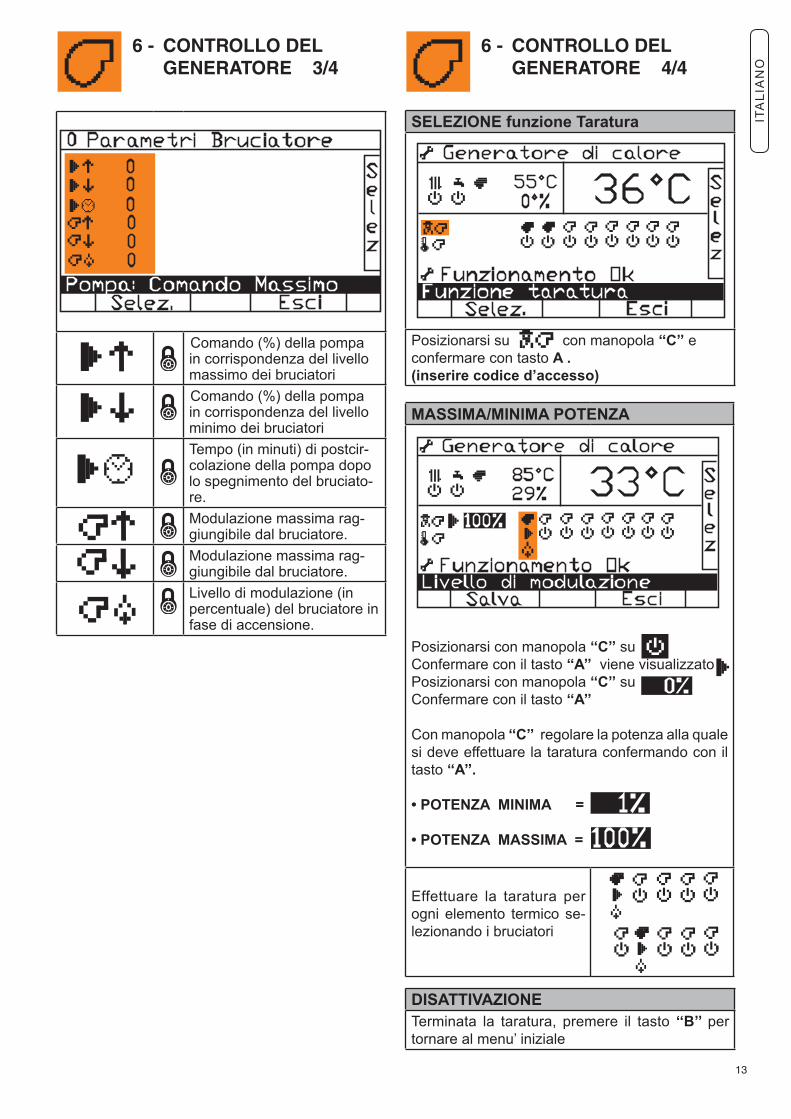
Comando (%) della pompa in corrispondenza del livello massimo dei bruciatori
Comando (%) della pompa in corrispondenza del livello minimo dei bruciatori
Tempo (in minuti) di postcir-colazione della pompa dopo lo spegnimento del bruciato-re.
Modulazione massima rag-giungibile dal bruciatore.
Modulazione massima rag-giungibile dal bruciatore.
Livello di modulazione (in percentuale) del bruciatore in fase di accensione.
SELEZIONE funzione Taratura
Posizionarsi su con manopola ‘‘C’’ e confermare con tasto A .(inserire codice d’accesso)
MASSIMA/MINIMA POTENZA
Posizionarsi con manopola ‘‘C’’ su Confermare con il tasto ‘‘A’’ viene visualizzatoPosizionarsi con manopola ‘‘C’’ su Confermare con il tasto ‘‘A’’
Con manopola ‘‘C’’ regolare la potenza alla quale si deve effettuare la taratura confermando con il tasto ‘‘A’’.
• POTENZA MINIMA =
• POTENZA MASSIMA =
Effettuare la taratura per ogni elemento termico se-lezionando i bruciatori
DISATTIVAZIONETerminata la taratura, premere il tasto ‘‘B’’ per tornare al menu’ iniziale
ITA
LIA
NO
14
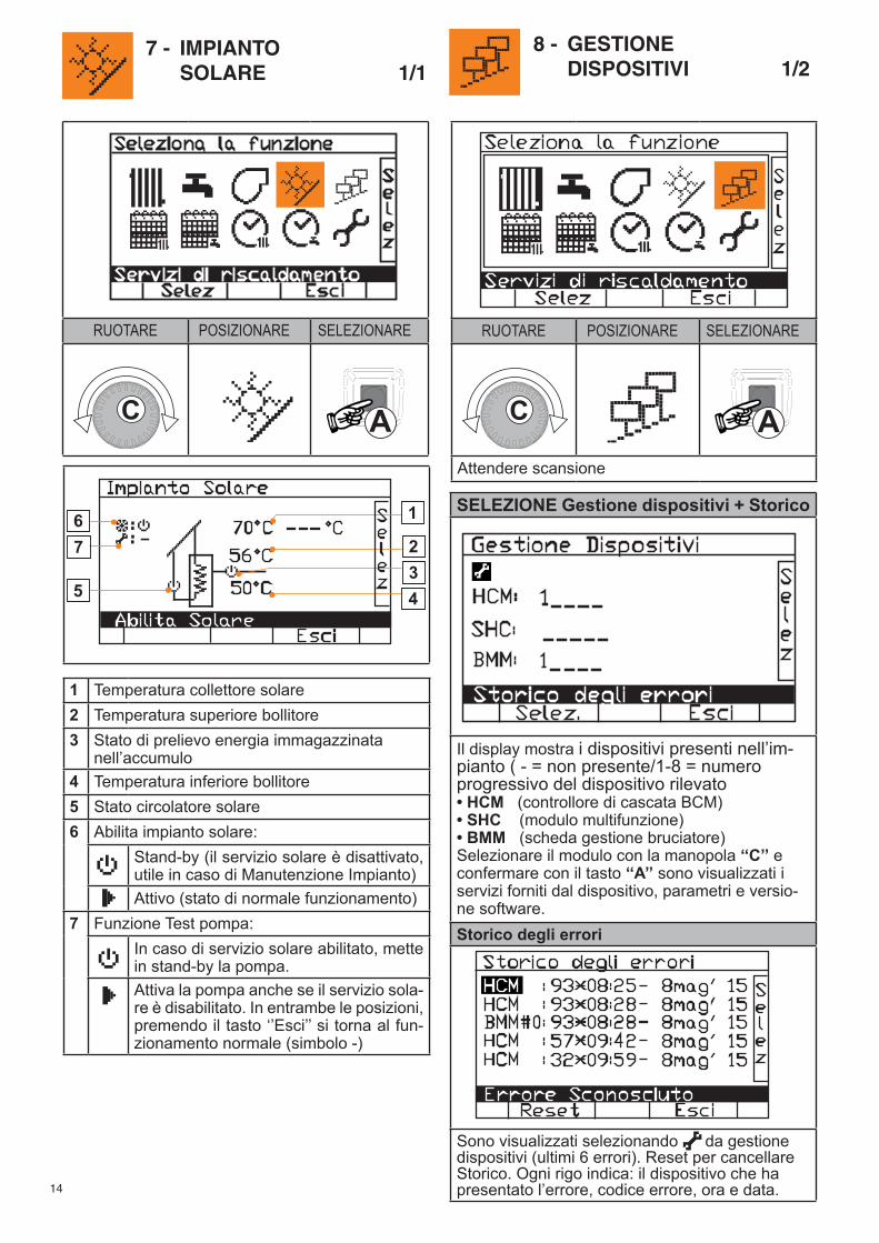
1 Temperatura collettore solare2 Temperatura superiore bollitore3 Stato di prelievo energia immagazzinata
nell’accumulo4 Temperatura inferiore bollitore 5 Stato circolatore solare6
Abilita impianto solare:Stand-by (il servizio solare è disattivato, utile in caso di Manutenzione Impianto)Attivo (stato di normale funzionamento)
7 Funzione Test pompa:In caso di servizio solare abilitato, mette in stand-by la pompa.Attiva la pompa anche se il servizio sola-re è disabilitato. In entrambe le posizioni, premendo il tasto ‘’Esci’’ si torna al fun-zionamento normale (simbolo -)
7 - IMPIANTO SOLARE 1/1
8 - GESTIONE DISPOSITIVI 1/2
RUOTARE POSIZIONARE SELEZIONARE
RUOTARE POSIZIONARE SELEZIONARE
Attendere scansione
SELEZIONE Gestione dispositivi + Storico
Il display mostra i dispositivi presenti nell’im-pianto ( - = non presente/1-8 = numero progressivo del dispositivo rilevato• HCM (controllore di cascata BCM) • SHC (modulo multifunzione)• BMM (scheda gestione bruciatore)Selezionare il modulo con la manopola ‘‘C’’ e confermare con il tasto ‘‘A’’ sono visualizzati i servizi forniti dal dispositivo, parametri e versio-ne software.Storico degli errori
Sono visualizzati selezionando da gestione dispositivi (ultimi 6 errori). Reset per cancellare Storico. Ogni rigo indica: il dispositivo che ha presentato l’errore, codice errore, ora e data.
15
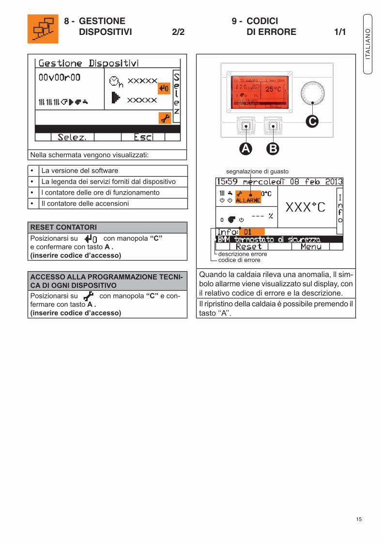
Nella schermata vengono visualizzati:
Quando la caldaia rileva una anomalia, ll sim-bolo allarme viene visualizzato sul display, con il relativo codice di errore e la descrizione.Il ripristino della caldaia è possibile premendo iltasto ‘‘A’’.
8 - GESTIONE DISPOSITIVI 2/2
9 - CODICI DI ERRORE 1/1
• La versione del software• La legenda dei servizi forniti dal dispositivo• l contatore delle ore di funzionamento• Il contatore delle accensioni
RESET CONTATORIPosizionarsi su con manopola ‘‘C’’ e confermare con tasto A .(inserire codice d’accesso)
ACCESSO ALLA PROGRAMMAZIONE TECNI-CA DI OGNI DISPOSITIVOPosizionarsi su con manopola ‘‘C’’ e con-fermare con tasto A .(inserire codice d’accesso)
ITA
LIA
NO
2
6 - OPERATING INSTRUCTION6.1 - CONTROL PANEL
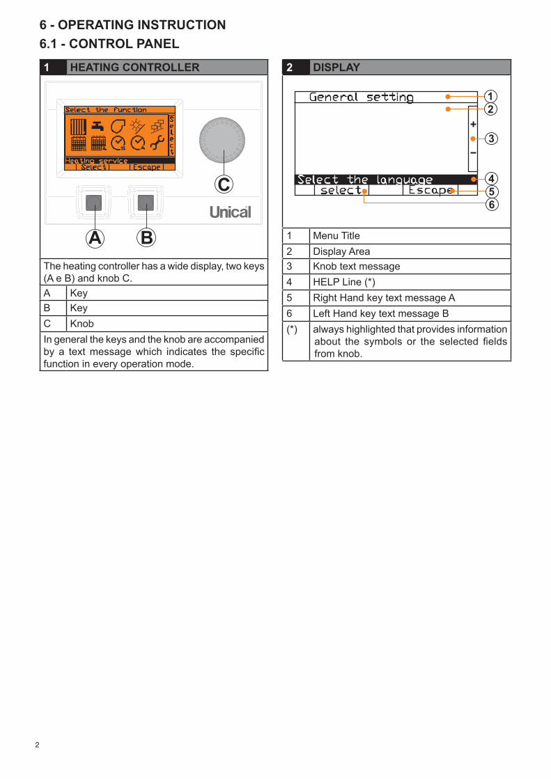
2 DISPLAY
1 Menu Title2 Display Area3 Knob text message4 HELP Line (*) 5 Right Hand key text message A6 Left Hand key text message B(*) always highlighted that provides information
about the symbols or the selected fields from knob.
1 HEATING CONTROLLER
The heating controller has a wide display, two keys (A e B) and knob C.A Key B Key C KnobIn general the keys and the knob are accompanied by a text message which indicates the specific function in every operation mode.
3
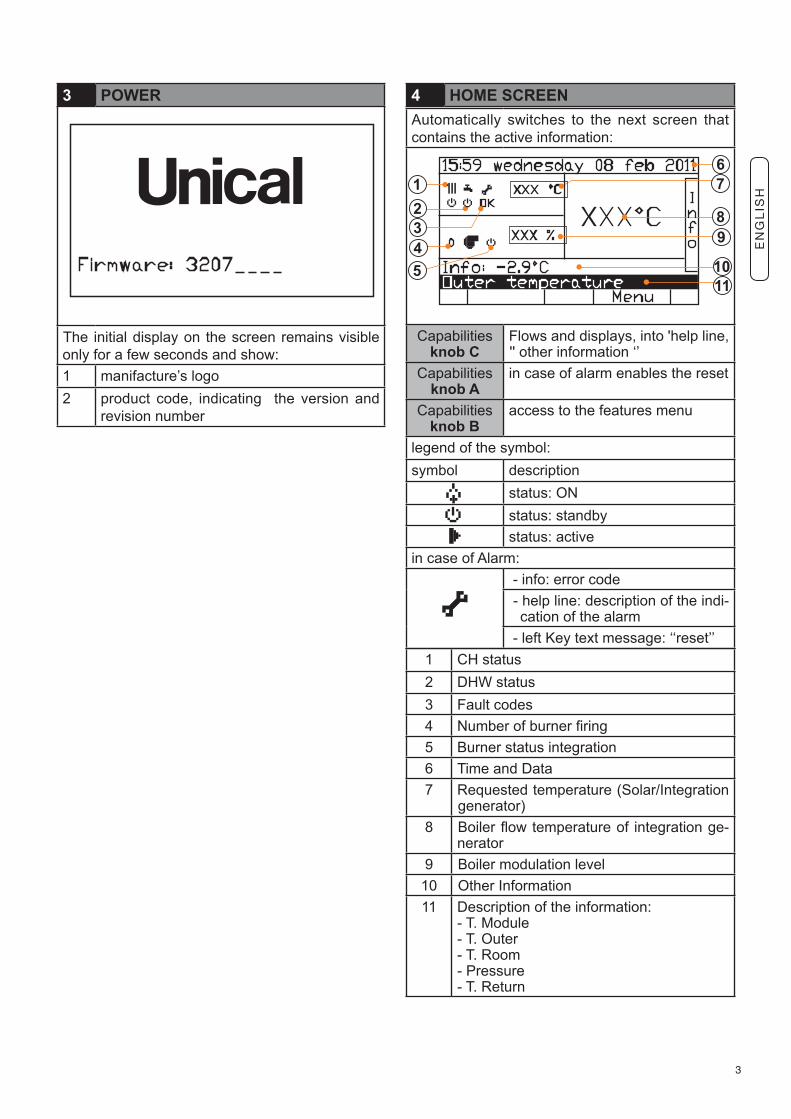
3 POWER
The initial display on the screen remains visible only for a few seconds and show: 1 manifacture’s logo2 product code, indicating the version and
revision number
4 HOME SCREENAutomatically switches to the next screen that contains the active information:
Capabilitiesknob C
Flows and displays, into 'help line, '' other information ‘’
Capabilitiesknob A
in case of alarm enables the reset
Capabilitiesknob B
access to the features menu
legend of the symbol:symbol description status: ON status: standby
status: activein case of Alarm:
- info: error code - help line: description of the indi-
cation of the alarm - left Key text message: ‘‘reset’’
1 CH status2 DHW status3 Fault codes4 Number of burner firing5 Burner status integration 6 Time and Data 7 Requested temperature (Solar/Integration
generator) 8 Boiler flow temperature of integration ge-
nerator9 Boiler modulation level
10 Other Information11 Description of the information:
- T. Module- T. Outer - T. Room- Pressure- T. Return
EN
GL
ISH
4
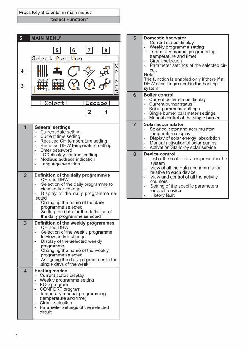
5 MAIN MENU’
1 General settings- Current date setting- Current time setting- Reduced CH temperature setting- Reduced DHW temperature setting- Enter password - LCD display contrast setting- ModBus address indication - Language selection
2 Definition of the daily programmes- CH and DHW- Selection of the daily programme to view and/or change- Display of the daily programme se-lected- Changing the name of the daily programme selected - Setting the data for the definition of the daily programme selected
3 Definition of the weekly programmes- CH and DHW- Selection of the weekly programme to view and/or change- Display of the selected weekly programme- Changing the name of the weekly programme selected - Assigning the daily programmes to the single days of the week
4 Heating modes- Current status display- Weekly programme setting- ECO program- CONFORT program - Temporary manual programming (temperature and time)- Circuit selection- Parameter settings of the selected circuit
Press Key B to enter in main menu: ‘‘Select Function’’
5 Domestic hot water- Current status display- Weekly programme setting- Temporary manual programming (temperature and time)- Circuit selection- Parameter settings of the selected cir-
cuitNote: The function is enabled only if there if a DHW circuit is present in the heating system
6 Boiler control- Current boiler status display- Current burner status- Boiler parameter settings- Single burner parameter settings- Manual control of the single burner
7 Solar accumulator- Solar collector and accumulator temperature display- Display of solar energy absorbtion- Manual activation of solar pumps- Activation/Stand-by solar service
8 Device control- List of the control devices present in the system- View of all the data and information relative to each device- View and control of all the activity counters- Setting of the specific parameters for each device- History fault
5
1 - GENERAL SETTING 1/4
1 - GENERAL SETTING 2/4
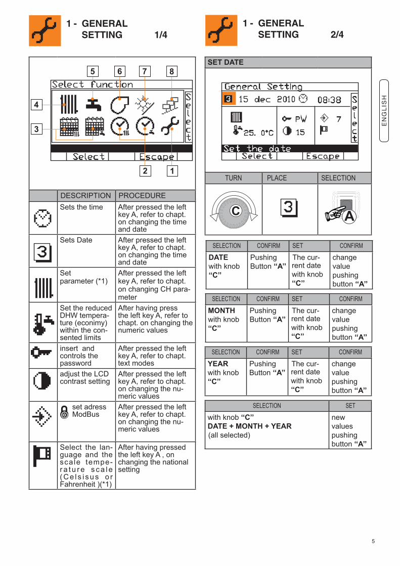
SET DATE
TURN PLACE SELECTION
SELECTION CONFIRM SET CONFIRM
MONTH with knob‘‘C’’
PushingButton ‘‘A’’
The cur-rent date with knob ‘‘C’’
change value pushing button ‘‘A’’
SELECTION SET
with knob ‘‘C’’DATE + MONTH + YEAR (all selected)
newvalues pushing button ‘‘A’’
SELECTION CONFIRM SET CONFIRM
YEARwith knob‘‘C’’
PushingButton ‘‘A’’
The cur-rent date with knob ‘‘C’’
change value pushing button ‘‘A’’
SELECTION CONFIRM SET CONFIRM
DATEwith knob‘‘C’’
PushingButton ‘‘A’’
The cur-rent date with knob ‘‘C’’
change value pushing button ‘‘A’’
DESCRIPTION PROCEDURESets the time After pressed the left
key A, refer to chapt. on changing the time and date
Sets Date After pressed the left key A, refer to chapt. on changing the time and date
Set parameter (*1)
After pressed the left key A, refer to chapt. on changing CH para-meter
Set the reduced DHW tempera-ture (econimy)within the con-sented limits
After having press the left key A, refer to chapt. on changing the numeric values
insert and controls the password
After pressed the left key A, refer to chapt. text modes
adjust the LCDcontrast setting
After pressed the left key A, refer to chapt. on changing the nu-meric values
set adress ModBus
After pressed the left key A, refer to chapt. on changing the nu-meric values
Select the lan-guage and the scale tempe-r a t u r e s c a l e ( C e l s i s u s o r Fahrenheit )(*1)
After having pressed the left key A , on changing the national setting
EN
GL
ISH
6
1 - GENERAL SETTING 3/4
1 - GENERAL SETTING 4/4
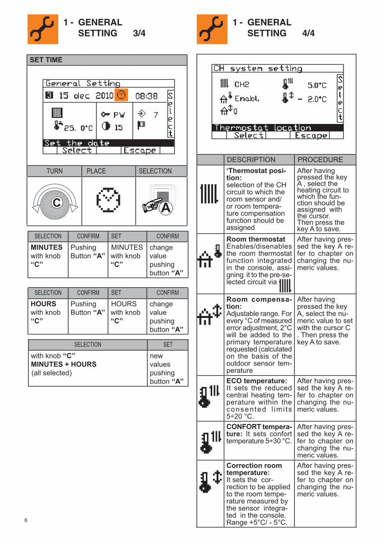
SET TIME
TURN PLACE SELECTION
SELECTION CONFIRM SET CONFIRM
HOURSwith knob‘‘C’’
PushingButton ‘‘A’’
HOURS with knob ‘‘C’’
change value pushing button ‘‘A’’
SELECTION SET
with knob ‘‘C’’MINUTES + HOURS (all selected)
newvalues pushing button ‘‘A’’
SELECTION CONFIRM SET CONFIRM
MINUTESwith knob‘‘C’’
PushingButton ‘‘A’’
MINUTES with knob ‘‘C’’
change value pushing button ‘‘A’’
DESCRIPTION PROCEDURE‘Thermostat posi-tion: selection of the CH circuit to which the room sensor and/or room tempera-ture compensation function should be assigned
After having pressed the key A , select the heating circuit to which the fun-ction should be assigned with the cursor.Then press the key A to save.
Room thermostat Enables/disenables the room thermostat function integrated in the console, assi-gning it to the pre-se-lected circuit via
After having pres-sed the key A re-fer to chapter on changing the nu-meric values.
Room compensa-tion:Adjustable range. For every °C of measured error adjustment, 2°C will be added to the primary temperature requested (calculated on the basis of the outdoor sensor tem-perature
After having pressed the key A, select the nu-meric value to set with the cursor C . Then press the key A to save.
ECO temperature:It sets the reduced central heating tem-perature within the consented l im i ts 5÷20 °C.
After having pres-sed the key A re-fer to chapter on changing the nu-meric values.
CONFORT tempera-ture: It sets confort temperature 5÷30 °C.
After having pres-sed the key A re-fer to chapter on changing the nu-meric values.
Correction room temperature:It sets the cor-rection to be applied to the room tempe-rature measured by the sensor integra-ted in the console. Range +5°C/ - 5°C.
After having pres-sed the key A re-fer to chapter on changing the nu-meric values.
7
2 - DAILY PROGRAM 1/1
TURN PLACE SELECTION
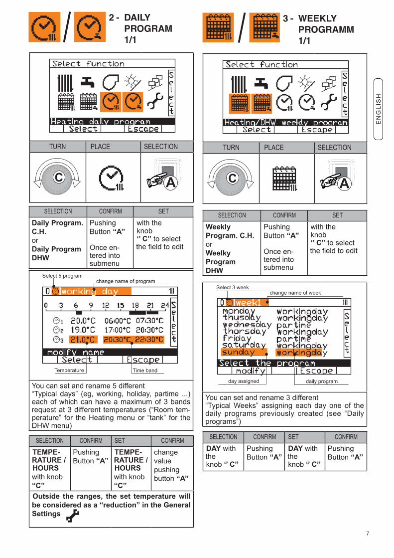
You can set and rename 5 different“Typical days” (eg, working, holiday, partime ...) each of which can have a maximum of 3 bands request at 3 different temperatures (“Room tem-perature” for the Heating menu or “tank” for the DHW menu)
SELECTION CONFIRM SET CONFIRM
TEMPE-RATURE /HOURS with knob ‘‘C’’
PushingButton ‘‘A’’
TEMPE-RATURE /HOURS with knob ‘‘C’’
change value pushing button ‘‘A’’
Outside the ranges, the set temperature will be considered as a “reduction” in the General Settings
SELECTION CONFIRM SET
Daily Program.C.H.orDaily ProgramDHW
PushingButton ‘‘A’’
Once en-tered into submenu
with theknob‘’ C’’ to select the field to edit
SELECTION CONFIRM SET
WeeklyProgram. C.H.orWeelkyProgramDHW
PushingButton ‘‘A’’
Once en-tered into submenu
with theknob‘’ C’’ to select the field to edit
3 - WEEKLY PROGRAMM 1/1
TURN PLACE SELECTION
You can set and rename 3 different“Typical Weeks” assigning each day one of the daily programs previously created (see “Daily programs”)
SELECTION CONFIRM SET CONFIRM
DAY with theknob ‘’ C’’
PushingButton ‘‘A’’
DAY with theknob ‘’ C’’
PushingButton ‘‘A’’
EN
GL
ISH
8
4 - CENTRAL HEATING FUNCTION 1/3
TURN PLACE SELECTION
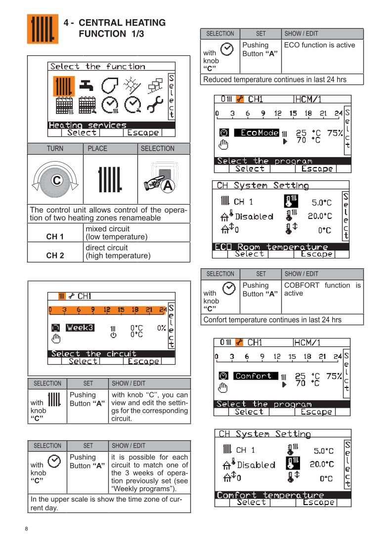
The control unit allows control of the opera-tion of two heating zones renameable
CH 1mixed circuit(low temperature)
CH 2direct circuit(high temperature)
SELECTION SET SHOW / EDIT
withknob‘‘C’’
PushingButton ‘‘A’’
with knob ‘‘C’’, you can view and edit the settin-gs for the corresponding circuit.
SELECTION SET SHOW / EDIT
withknob‘‘C’’
PushingButton ‘‘A’’
it is possible for each circuit to match one of the 3 weeks of opera-tion previously set (see “Weekly programs”).
In the upper scale is show the time zone of cur-rent day.
SELECTION SET SHOW / EDIT
withknob‘‘C’’
PushingButton ‘‘A’’
ECO function is active
Reduced temperature continues in last 24 hrs
SELECTION SET SHOW / EDIT
withknob‘‘C’’
PushingButton ‘‘A’’
COBFORT function is active
Confort temperature continues in last 24 hrs
9
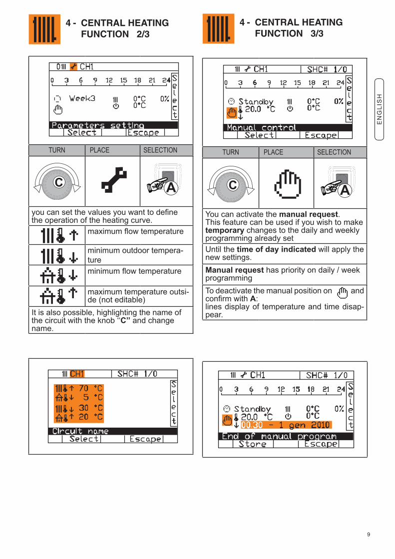
4 - CENTRAL HEATING FUNCTION 2/3
4 - CENTRAL HEATING FUNCTION 3/3
TURN PLACE SELECTION
you can set the values you want to define the operation of the heating curve.
maximum flow temperature
minimum outdoor tempera-tureminimum flow temperature
maximum temperature outsi-de (not editable)
It is also possible, highlighting the name of the circuit with the knob ‘‘C’’ and change name.
TURN PLACE SELECTION
You can activate the manual request.This feature can be used if you wish to make temporary changes to the daily and weekly programming already setUntil the time of day indicated will apply the new settings.Manual request has priority on daily / week programmingTo deactivate the manual position on and confirm with A:lines display of temperature and time disap-pear.
EN
GL
ISH
10
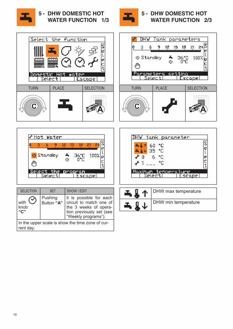
5 - DHW DOMESTIC HOT WATER FUNCTION 1/3
5 - DHW DOMESTIC HOT WATER FUNCTION 2/3
SELECTION SET SHOW / EDIT
withknob‘‘C’’
PushingButton ‘‘A’’
it is possible for each circuit to match one of the 3 weeks of opera-tion previously set (see “Weekly programs”).
In the upper scale is show the time zone of cur-rent day.
DHW max temperature
DHW min temperature
TURN PLACE SELECTION
TURN PLACE SELECTION
11
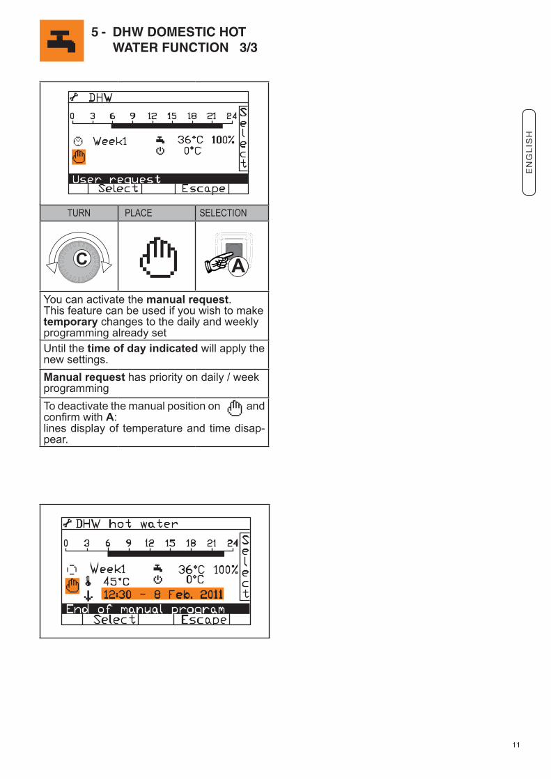
5 - DHW DOMESTIC HOT WATER FUNCTION 3/3
TURN PLACE SELECTION
You can activate the manual request.This feature can be used if you wish to make temporary changes to the daily and weekly programming already setUntil the time of day indicated will apply the new settings.Manual request has priority on daily / week programmingTo deactivate the manual position on and confirm with A:lines display of temperature and time disap-pear.
EN
GL
ISH
12
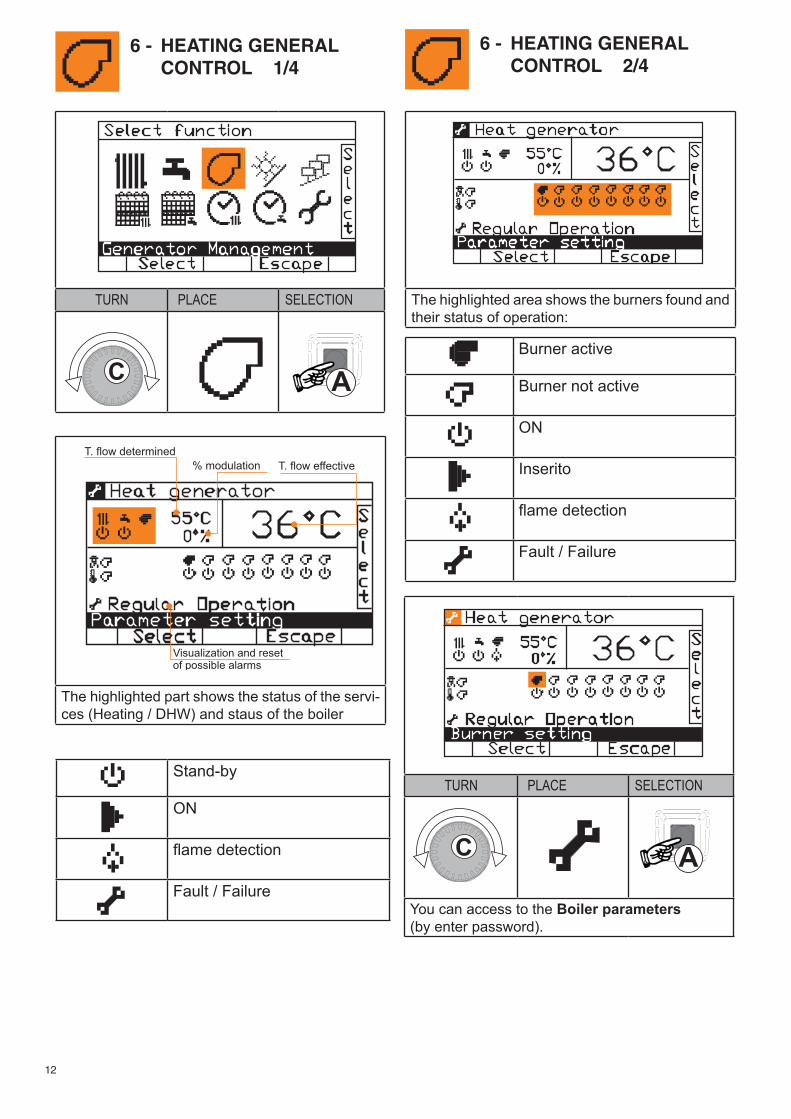
The highlighted part shows the status of the servi-ces (Heating / DHW) and staus of the boiler
The highlighted area shows the burners found and their status of operation:
Stand-by
ON
flame detection
Fault / Failure
Burner active
Burner not active
ON
Inserito
flame detection
Fault / Failure
TURN PLACE SELECTION
You can access to the Boiler parameters(by enter password).
6 - HEATING GENERAL CONTROL 1/4
6 - HEATING GENERAL CONTROL 2/4
TURN PLACE SELECTION
13
6 - HEATING GENERAL CONTROL 3/4
6 - HEATING GENERAL CONTROL 4/4
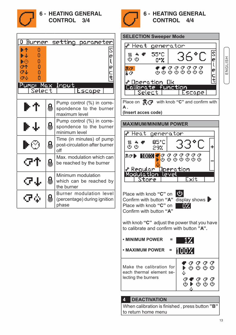
Pump control (%) in corre-spondence to the burner maximum level
Pump control (%) in corre-spondence to the burner minimum level
Time (in minutes) of pump post-circulation after burner off
Max. modulation which can be reached by the burner
Minimum modulation which can be reached by the burner
Burner modulation level (percentage) during ignition phase
SELECTION Sweeper Mode
Place on with knob ‘‘C’’ and confirm with A .(Insert acces code)
MAXIMUM/MINIMUM POWER
Place with knob ‘‘C’’ on Confirm with button ‘‘A’’ display showsPlace with knob ‘‘C’’ on Confirm with button ‘‘A’’
with knob ‘‘C’’ adjust the power that you have to calibrate and confirm with button ’’A’’.
• MINIMUM POWER =
• MAXIMUM POWER =
Make the calibration for each thermal element se-lecting the burners
4 DEACTIVATIONWhen calibration is finished , press button ’’B’’ to return home menu
EN
GL
ISH
14
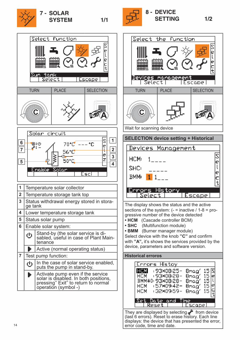
1 Temperature solar collector2 Temperature storage tank top3 Status withdrawal energy stored in stora-
ge tank4 Lower temperature storage tank5 Status solar pump6
Enable solar system:Stand-by (the solar service is di-sabled, useful in case of Plant Main-tenanceActive (normal operating status)
7 Test pump function:In the case of solar service enabled, puts the pump in stand-by.Activate pump even if the service solar is disabled. In both positions, pressing’’ Exit’’ to return to normal operation (symbol -)
7 - SOLAR SYSTEM 1/1
8 - DEVICE SETTING 1/2
TURN PLACE SELECTION
TURN PLACE SELECTION
Wait for scanning device
SELECTION device setting + Historical
The display shows the status and the active sections of the system: (- = inactive / 1-8 = pro-gressive number of the device detected• HCM (Cascade controller BCM) • SHC (Multifunction module)• BMM (Burner manager module)Select device with the knob ’’C’’ and confirm with ’’A’’, it’s shows the services provided by the device, parameters and software version.
Historical erroros
They are displayed by selecting from device (last 6 errors). Reset to erase history. Each line displays: the device that has presented the error, error code, time and date.
15
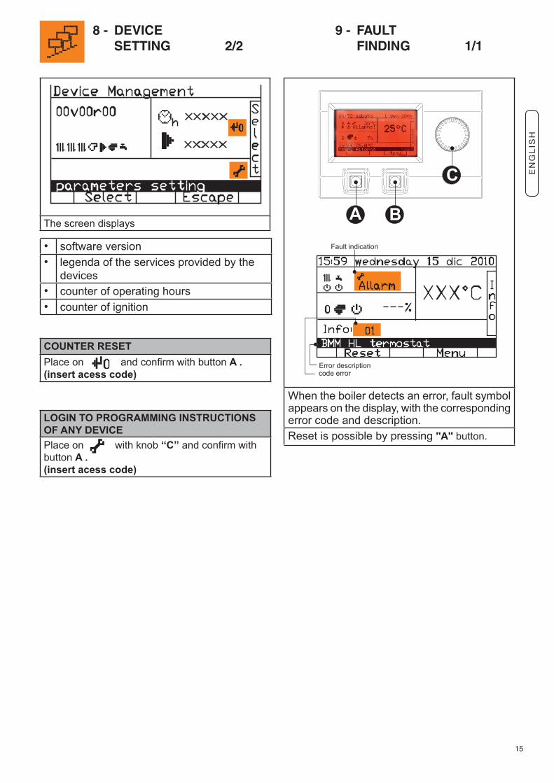
The screen displays
When the boiler detects an error, fault symbol appears on the display, with the corresponding error code and description.Reset is possible by pressing ''A'' button.
8 - DEVICE SETTING 2/2
9 - FAULT FINDING 1/1
• software version• legenda of the services provided by the
devices• counter of operating hours• counter of ignition
COUNTER RESET Place on and confirm with button A .(insert acess code)
LOGIN TO PROGRAMMING INSTRUCTIONS OF ANY DEVICEPlace on with knob ‘‘C’’ and confirm with button A .(insert acess code)
EN
GL
ISH


Unical declina ogni responsabilità per le possibili inesattezze se dovute ad errori di trascrizione o di stampa. Si riserva altresì il diritto di apportare ai propri prodotti quelle modifiche che riterrà necessarie o utili, senza pregiudicarne le caratteristiche essenziali.
0033
3843
-
2a ed
izio
ne 0
5/15
/ 2st
edi
tion
05/1
5
46033 casteldario - mantova - italia - tel. +39 0376 57001 - fax +39 0376 660556 [email protected] - [email protected] - www.unical.eu
AG S.p.A.
Unical declines every responsibility for the possible inaccuracies if owed to errors of transcript or press. Also reserves the right to bring those changes that it will hold necessary to it own products or profits, without jeopardizing its essential characteristics.
www.unical.eu