Embed Size (px)
Citation preview
DPF2013-221November 10, 2021
Design and Testing of a Wireless Demonstrator for LargeInstrumentation Systems
H. Sahoo1, P. De Lurgio, Z. Djurcic, G. Drake, A. Kreps and M.Oberling
High Energy Physics DivisionArgonne National Laboratory, Argonne, IL-60439, USA
R. Hashemian and T. Pearson
Electrical Engineering DepartmentNorthern Illinois University, Dekalb, IL-60115, USA
In this proceeding, we report the development of a wireless demon-strator intended to readout instrumentation systems having thousandsof channels. A data acquisition system was designed and tested basedon compliant implementation of 802.11n based hardware and protocols.This project is for large detectors containing photomultiplier tubes. Bothfree-space optical and radio frequency techniques were tested for wirelesspower transfer. The front-end circuitry, including a high-voltage powersupply was powered wirelessly, thus creating an all-wireless detector read-out. The system was successfully tested as a single detector module, whichwas powered wirelessly and transmitted data wirelessly. The performanceof the prototype system and how a large scale implementation of the sys-tem might be realized are described in this proceeding.
PRESENTED AT
DPF 2013The Meeting of the American Physical Society
Division of Particles and FieldsSanta Cruz, California, August 13–17, 2013
1 Presented by Himansu Sahoo at the DPF 2013 Meeting of the American Physical SocietyDivision of Particles and Fields, Santa Cruz, California, August 13-17, 2013.
arX
iv:1
310.
1819
v1 [
phys
ics.
ins-
det]
7 O
ct 2
013

1 Motivation for Wireless DAQ
In several areas of scientific research, the size and complexity of detectors have becomeexceedingly large. For example, detectors used in Nuclear and Elementary ParticlePhysics can have dimensions of the order of 10-100 meters and contain thousandsto millions of readout channels. This create a significant challenge to power theelectronics as well as to transfer data. Traditional approach of using electrical cableshave become complicated and expensive at a larger scale. Specially, cabling is notpractical for detectors in remote location or in hostile environment. To overcome theseproblems, we developed an alternative approach that uses wireless techniques to powerand transmit data. A stand-alone photomultiplier tube (PMT) base detector wasdesigned and tested in free space, that operates from wireless power and then transfersdata wirelessly. We carried out this case study for large detectors containing PMTs,which are commonly used in high energy physics research. The primary purpose isto ascertain the feasibility and practicality of such devices as single detector modulesthat can be configured as arrays in a large detector. This approach has potential toeliminate the need of expensive and massive cable plants, to simplify the process ofinstallation and repair, and to reduce the detector dead mass.
2 Design Considerations
We have explored different technologies, such as free-space optical and radio fre-quency (RF) to wirelessly transmit data and power. But, we selected the technologythat is inexpensive and off-the-self that can be easily implemented while meeting theperformance goals of our R&D project.
For wireless data transmission, optical links support higher data rates (1 Gbit/s [1])than those use RF. However, RF transmission does not require line-of-sight, and anindividual receiver (i.e. access point) can communicate with many front-ends. Sinceboth of these advantages provide significant simplification and cost reduction, RFdata transmission was chosen for this project. We focused on wireless local area net-work (WLAN) technologies with 802.11n variant, because it offers the highest datathroughput and has sufficient range for data transmission. For instance, a singlesteam 802.11n link has a total data rate of approximately 65 Mbit/s [2]. While thisis sufficient for our single prototype front-end, it provides greater challenge for largedetectors in transferring data from thousands of readout channels over a limited andcommon frequency spectrum. We addressed this problem by filling the available fre-quency space with many access points, as described in Ref. [3]. One of the frequencyrange in 802.11n is centered around 5.5 GHz with an overall bandwidth of approx-imately 1.2 GHz (4.9−6.1 GHz). Single stream 802.11n access points can have anindividual operating bandwidth of 20 MHz. This enabled us to populate up to 48
1

access points with the usable 1.2 GHz frequency spectrum, each communicating tonearly 64 PMT wireless read-outs or front-ends (a total of 3072 front-ends). Thisdesign provided an overall data throughput of 1.68 Gbit/s.
For wireless power transmission, we tested both optical and RF power transfermethods. The optical power demonstrator utilizes a high power light-emitting diode(LED) that is collimated into an 8 inch diameter beam and is received by a photo-voltaic (PV) panel, as shown in Fig. 1. The LED is an OSRAM SFH 4751 with 3.5W optical output, operated at a maximum DC current of 1 A. The LED wavelengthis 940 nm which matches the peak efficiency of the Delsolar 156 × 156 mm2 photo-voltaic cell used in our 312 × 280 mm2 PV panel array. This test system met ourrequirements of receiving 250 mW of power at 5 meters.
Distance (m)
2 3 4 5 6 7
Po
we
r re
ce
ive
d (
mW
)
200
250
300
350
400
450
500
550
600
Figure 1: Apparatus for optical power transmission. Left figure shows the tubecontaining LED and lens, and the photovoltaic receiver at the far end. Right figureshows the power received (mW) by the photovoltaic panel as a function of distance(m) from the optical source.
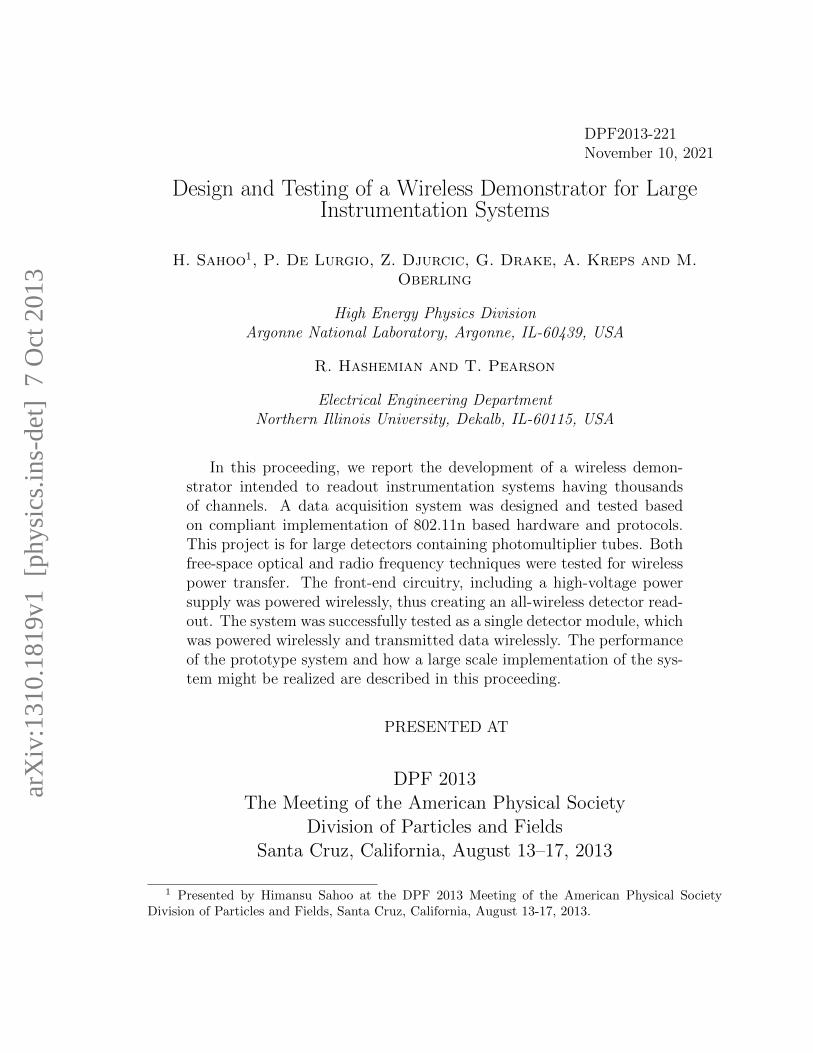
The RF power demonstrator uses high-gain directional microwave antennas. Thesetup consisted of a function generator driving a 14 dBi gain Yagi antenna at 915 MHzwith an output power of 10 dBm, which was received by a 11 dBi gain patch antenna,as shown in Fig. 2. The power received was measured in free space to minimizescattering from surrounding objects. As the transmission distance increased, thepower received fell rapidly; the power loss being 20 dBm at 5 meters. Thus, a 25 Wsource will be required to receive our targeted 250 mW power.
For this feasibility study, we chose the optical method to implement in our proto-type. It provided a DC source at the receiver end, which is relatively easy to utilize.In order to transmit RF power, it has to be converted into a DC supply at the re-ceiver end, which is commercially available for only a 100 mW power [4]. However,RF power could be a better choice for a large detector because one source can power
2
Distance (m)1 2 3 4 5 6 7 8
Po
wer
loss (
dB
)
30
25
20
15
10
5
0
Figure 2: Apparatus for RF power transmission. Left figure shows the RF transmit-ter (14 dBi gain Yagi antenna) in the foreground, with the RF receiver (11 dBi gainpatch antenna) at the far end. Right figure shows the power loss (dB) as a functionof distance (m) from the source.
many front-ends, thereby reducing the complexity and cost of the system.
3 Wireless Data Acquisition System
The wireless prototype system is comprised of four boards: a power board, whichreceives wireless power and generates different voltages needed by the system; a digitalboard, which processes the data and does wireless data transmission; a front-endboard, which does shaping and digitization of the PMT signal; and a high voltageboard, which generates high voltage for the PMT. The high voltage board uses astandard Cockroft-Walton (CW) switching circuit to boost the 24 V input voltageup to 2000 V, which is needed for the 10-stage tube PMT. We chose a large 10 inchdiameter PMT, a Hamamatsu R7081HQE [5], which has dark noise rate of ∼10 kHz.All the boards are physically arranged inside a tube as shown in Fig. 3. One end ofthe tube was fitted into the base of the PMT and the other end was connected to aphotovoltaic panel. Details of the wireless demonstrator are described in Ref. [3].
The prototype readout system consisted of a Scientific Linux computer and a CiscoE3000 [6] running DD-WRT firmware as an access point. The front-end transmitteddata wirelessly once per second as a single UDP packet using 802.11n in the 5 GHzband. A readout program running on the server received and stored the incomingUDP packets. For each asynchronous PMT trigger, we stored the pulse height (2bytes) and time stamp (4 bytes) information. We have collected data with the proto-type system operated from wireless power (using the optical source and received bythe photovoltaic panel) and with wireless data readout. The performance achieved
3

Figure 3: The printed circuit boards used in the wireless prototype system (left) andconfiguration of the prototype readout system (right).
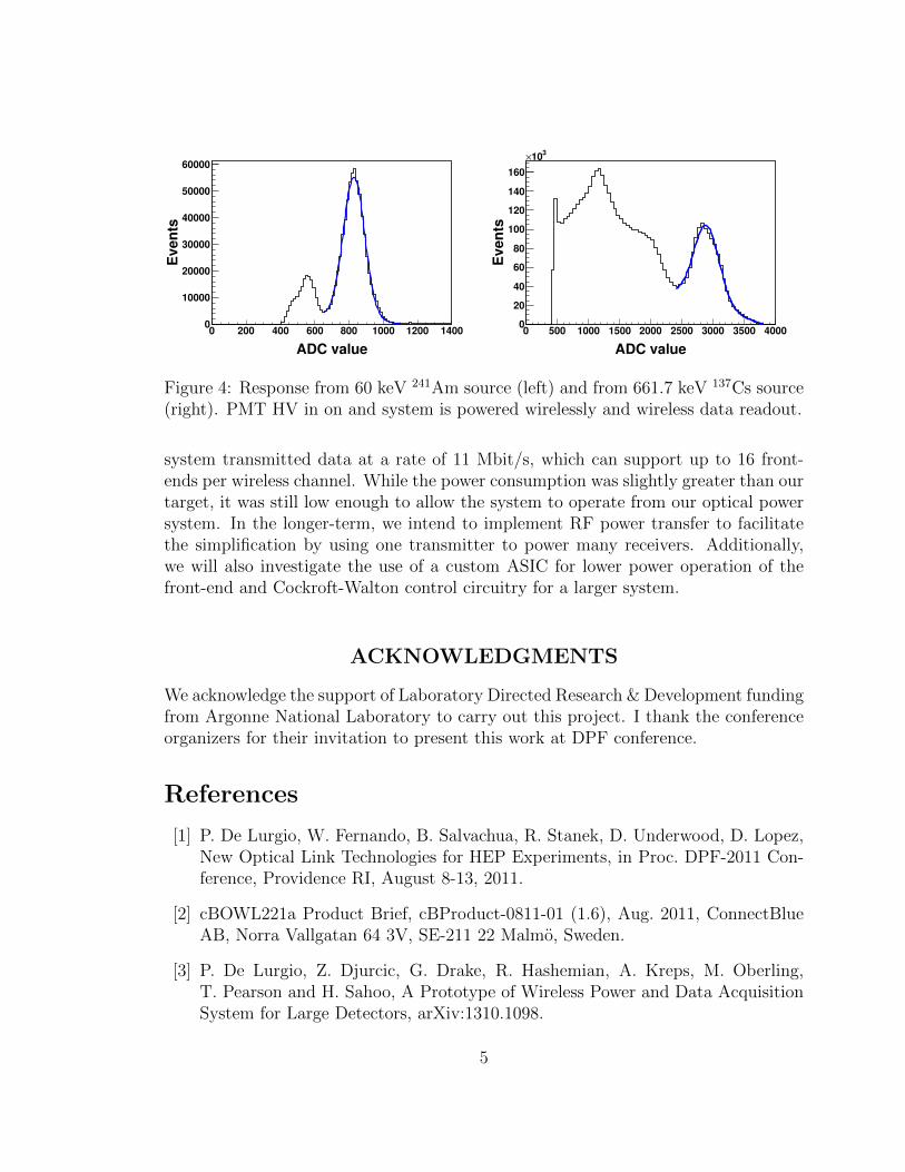
along with target specifications are summarized in Table 1. The system is capable ofsending greater than 10k events/s. To test the data acquisition capability, a sodiumiodide crystal was attached to the PMT and tested with 241Am and 137Cs sources.The 137Cs data yields a 17% energy resolution with sodium iodide. The response fromthe sources are shown in Fig. 4.
Table 1: Summary of the initial goals and achieved performance for the wireless dataacquisition system.
Specification Target PerformanceTotal power consumption (@ 10 kHz) 250 mW 386 mW
Digital 120 mW 216 mWFront-end 30 mW 39 mW
HV 80 mW 131 mWMaximum event rate 10 kHz 80 kHz
Data transfer rate 35 Mb/s 11 Mb/sBit Error Rate < 1×10⁻¹² Dropped Packets
4 Summary
We successfully built and tested a wireless demonstrator, which was implemented ina photomultiplier tube base and received power and transmitted data wirelessly. The
4
ADC value
0 200 400 600 800 1000 1200 1400
Ev
en
ts
0
10000
20000
30000
40000
50000
60000
ADC value
0 500 1000 1500 2000 2500 3000 3500 4000
Ev
en
ts
0
20
40
60
80
100
120
140
160
310×
Figure 4: Response from 60 keV 241Am source (left) and from 661.7 keV 137Cs source(right). PMT HV in on and system is powered wirelessly and wireless data readout.
system transmitted data at a rate of 11 Mbit/s, which can support up to 16 front-ends per wireless channel. While the power consumption was slightly greater than ourtarget, it was still low enough to allow the system to operate from our optical powersystem. In the longer-term, we intend to implement RF power transfer to facilitatethe simplification by using one transmitter to power many receivers. Additionally,we will also investigate the use of a custom ASIC for lower power operation of thefront-end and Cockroft-Walton control circuitry for a larger system.
ACKNOWLEDGMENTS
We acknowledge the support of Laboratory Directed Research & Development fundingfrom Argonne National Laboratory to carry out this project. I thank the conferenceorganizers for their invitation to present this work at DPF conference.
References
[1] P. De Lurgio, W. Fernando, B. Salvachua, R. Stanek, D. Underwood, D. Lopez,New Optical Link Technologies for HEP Experiments, in Proc. DPF-2011 Con-ference, Providence RI, August 8-13, 2011.
[2] cBOWL221a Product Brief, cBProduct-0811-01 (1.6), Aug. 2011, ConnectBlueAB, Norra Vallgatan 64 3V, SE-211 22 Malmo, Sweden.
[3] P. De Lurgio, Z. Djurcic, G. Drake, R. Hashemian, A. Kreps, M. Oberling,T. Pearson and H. Sahoo, A Prototype of Wireless Power and Data AcquisitionSystem for Large Detectors, arXiv:1310.1098.
5

[4] P1110 915 MHz RF PowerharvesterTM Receiver Datasheet, Rev A, Apr. 2010,Powercast Corporation, 566 Alpha Drive, Pitsburgh, PA 15238, United States.
[5] R7081HQE Datasheet, Nov. 12. 2003, Hamamatsu Photonics K.K., 325-6,Sunayama-cho, Naka-ku, Hamamatsu City, Shizuoka Pref., 430-8587, Japan.
[6] E3000 Datasheet, 10031010NC-JL, Oct. 2010, Cisco Systems, Inc., 170 WestTasman Dr., San Jose, CA 95134, United States.
6