Embed Size (px)
DESCRIPTION
H2O Single Coil Indirect IOM Rev. B 812
Citation preview
7/21/2019 H2O Single Coil Indirect IOM Rev. B 812
http://slidepdf.com/reader/full/h2o-single-coil-indirect-iom-rev-b-812 1/24
H2O
INDIRECT-FIRED
WATER HEATERS
FOR SINGLE WATER HEATER
INSTALLATIONS
INSTALLATION, OPERATION &
MAINTENANCE MANUAL
P/N# 615000054, Rev. B [08/20
MODELS
H2OI30
H2OI40
H2OI40L
H2OI50H
2OI60
H2OI60L
H2OI80
H2OI80C
H2OI80HO
H2OI80HOC
H2OI115H
2OI115C
H2OI115HO
H2OI115HOC
An ISO 9001-2008 Certified Company
2201 Dwyer Avenue, Utica NY 13501
web site: www.ecrinternational.com
Information and specifications outlined in this manual in effect at the time ofprinting of this manual. ECR International reserves the right to discontinue, chan
specifications or system design at any time without notice and without incurringany obligation, whatsoever.
Conforms to UL STD 174
Certi fi ed to CAN/CSA STD C22.2 No. 110-94
30, 40, 50, 60, 80, 115 Gallon
L = Low Boy Profile
C = Commercial Pipe Connections
HO = High Output
7/21/2019 H2O Single Coil Indirect IOM Rev. B 812
http://slidepdf.com/reader/full/h2o-single-coil-indirect-iom-rev-b-812 2/24
2
I. General Information
IMPORTANT INFORMATION – READ CAREFULLY
NOTE: Equipment shall be installed in accordance with those installation regulations required in the area where theinstallation is to be made. These regulations shall be carefully followed in all cases. Authorities having jurisdiction shallbe consulted before installations are made. All wiring on water heaters shall be in accordance with the National Electrica
Code and/or local regulations.
Improper installation, adjustment, alteration, service or maintenance can cause property damage, personal injury, or losof life. Read and understand the entire manual before attempting installation, start-up, operation, or service. Installationand service must be performed only by an experienced, skilled installer or service agency.
This water heater contains very hot water under high pressure. Do not unscrew any pipe ttings or attempt to disconnecany components of this water heater without positively assuring that the water is cool and has no pressure. Always wearprotective clothing and equipment when installing, starting up or servicing this water heater to prevent scalding injuries.Do not rely on the pressure and temperature gauges to determine the temperature and pressure of the water heater.
This water heater contains components that become very hot when the boiler is operating. Do not touch any componentunless they are cool.
Failure to follow all instructions in the proper order can cause personal injury or death. Read all instructions, including althose contained in component manufacturers’ manuals before installing, starting up, operating, maintaining, or servicingthe water heater.
To reduce the risk of excessive pressures and temperatures in this water heater, install temperature and pressureprotective equipment required by local codes but no less than a combination temperature relief valve certied by anationally recognized testing laboratory that maintains periodic inspection of production of listed equipment or materialsas meeting the requirements for Relief Valves and Automatic Shutoff Devices for Hot Water Supply Systems, ANSI Z21.2
latest edition. This valve must be marked with a maximum set pressure not to exceed the marked working pressure ofthe water heater. Install the valve into an opening provide and marked for this purpose in the water heater, and orient itor provide tubing so that any discharge from the valve will exit only within 6 inches above, or at any distance below, thestructural oor, and cannot contact any live electrical part. The discharge opening must not be blocked or reduced in sizeunder any circumstances.
Heat transfer medium must be water or other non-toxic uid having a toxicity rating or class of 1, as listed in clinicalToxicology of Commercial Products, latest edition. The pressure of the heat transfer medium must be limited to amaximum of 60 psig by a listed safety or relief valve.
I. General Information & Safety Instructions ................................................................................ 2
II. Pre-installation Considerations ................................................................................................ 4
III. Piping .................................................................................................................................. 9
IV. Electrical .............................................................................................................................13
V. Operation ............................................................................................................................13
VI. Maintenance ........................................................................................................................16
VII. Troubleshooting ...................................................................................................................16
Table of Contents
7/21/2019 H2O Single Coil Indirect IOM Rev. B 812
http://slidepdf.com/reader/full/h2o-single-coil-indirect-iom-rev-b-812 3/24
7/21/2019 H2O Single Coil Indirect IOM Rev. B 812
http://slidepdf.com/reader/full/h2o-single-coil-indirect-iom-rev-b-812 4/24
4
II. Pre-installation Considerations
Inspect shipment carefully for signs of damage. All equipment is carefully inspected and packed. ECR’s responsibilityceases upon delivery of the water heater to the carrier in good condition. Any claims for damage or shortage, mustbe led immediately against the carrier by the consignee. No claims for variances or shortages will be allowed by theManufacturer, unless they are presented within sixty days after receipt of the equipment.
Installation must conform to the requirements of the authority having jurisdiction. In the absence of such requirements,installation must conform to the National Plumbing Code and the National Electrical Code ANSI/NFPA No. 70, currentedition.
IMPORTANT CONSIDERATIONS BEFORE INSTALLATION
1. Water Heater Sizing.
Choose the water heater model based on the expected water usage for the given site. The average residence with oneshower or more will require a Model 40 or larger. The Model 30 should only be considered for residences with minimalwater demand, or for commercial applications without showers. See tables on pages 17 and 18.
Consult ASHRAE sizing guides and other references.
Factors that increase water demand dramatically include high ow shower heads, hot tubs, and the use of more than onshower at a time. Increase the tank size if these factors are present. Consult ASHRAE sizing guides or other references.
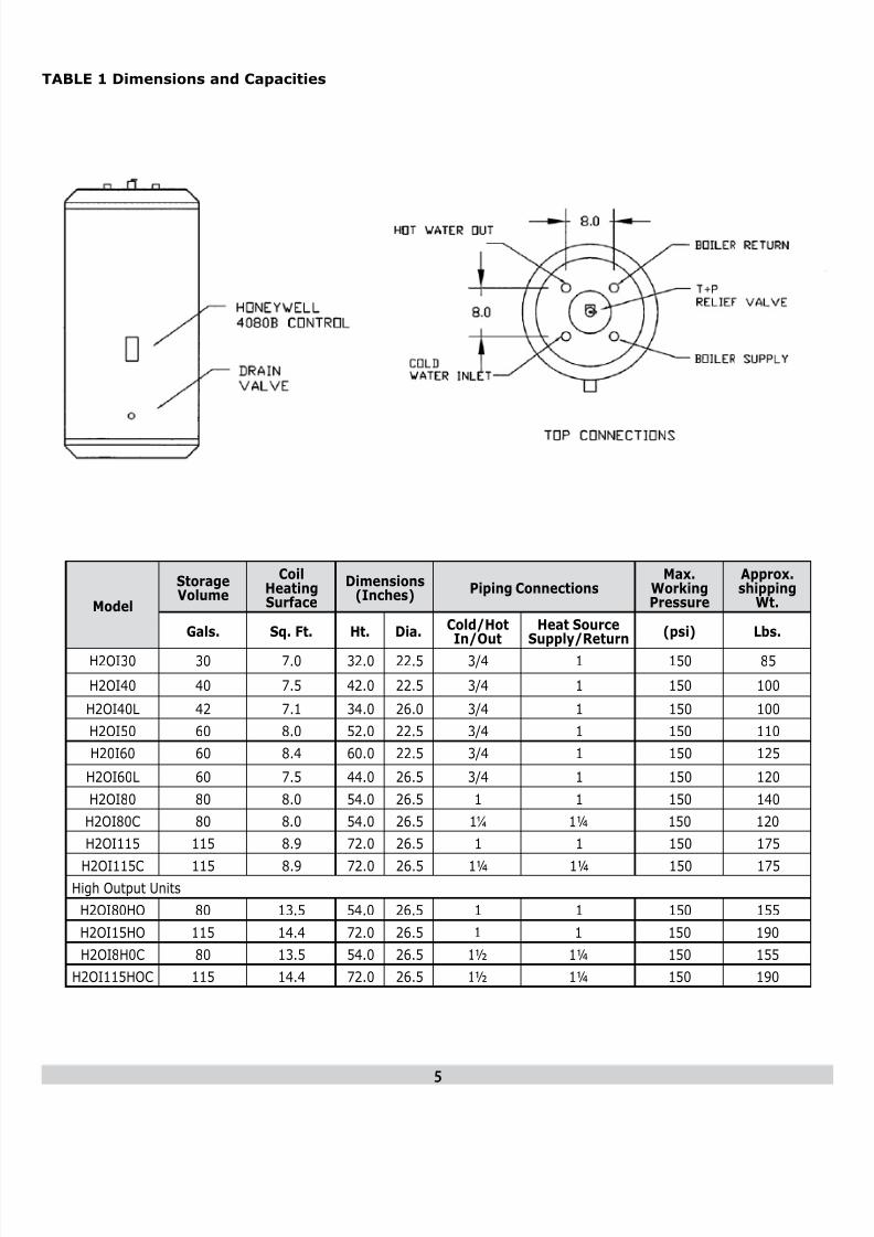
Dimensions, weights, ratings, and capacities are outlined in Tables 1 and 2.
2. Boiler Sizing.
The water heater will provide the rated performance only if it is used with a boiler with a heating capacity of at leastas much as the capacity ratings in Table 2. If the boiler has less capacity, the water heating output will be reduced. To
determine performance with other boiler outputs, refer to the expanded capacity tables in the Appendix.
7/21/2019 H2O Single Coil Indirect IOM Rev. B 812
http://slidepdf.com/reader/full/h2o-single-coil-indirect-iom-rev-b-812 5/24
5
Model
StorageVolume
CoilHeatingSurface
Dimensions(Inches)
Piping ConnectionsMax.
WorkingPressure
Approx.shipping
Wt.
Gals. Sq. Ft. Ht. Dia.Cold/HotIn/Out
Heat SourceSupply/Return
(psi) Lbs.
H2OI30 30 7.0 32.0 22.5 3/4 1 150 85
H2OI40 40 7.5 42.0 22.5 3/4 1 150 100
H2OI40L 42 7.1 34.0 26.0 3/4 1 150 100
H2OI50 60 8.0 52.0 22.5 3/4 1 150 110
H20I60 60 8.4 60.0 22.5 3/4 1 150 125
H2OI60L 60 7.5 44.0 26.5 3/4 1 150 120
H2OI80 80 8.0 54.0 26.5 1 1 150 140
H2OI80C 80 8.0 54.0 26.5 1¼ 1¼ 150 120
H2OI115 115 8.9 72.0 26.5 1 1 150 175
H2OI115C 115 8.9 72.0 26.5 1¼ 1¼ 150 175High Output Units
H2OI80HO 80 13.5 54.0 26.5 1 1 150 155
H2OI15HO 115 14.4 72.0 26.5 1 1 150 190
H2OI8H0C 80 13.5 54.0 26.5 1½ 1¼ 150 155
H2OI115HOC 115 14.4 72.0 26.5 1½ 1¼ 150 190
TABLE 1 Dimensions and Capacities
7/21/2019 H2O Single Coil Indirect IOM Rev. B 812
http://slidepdf.com/reader/full/h2o-single-coil-indirect-iom-rev-b-812 6/24
6
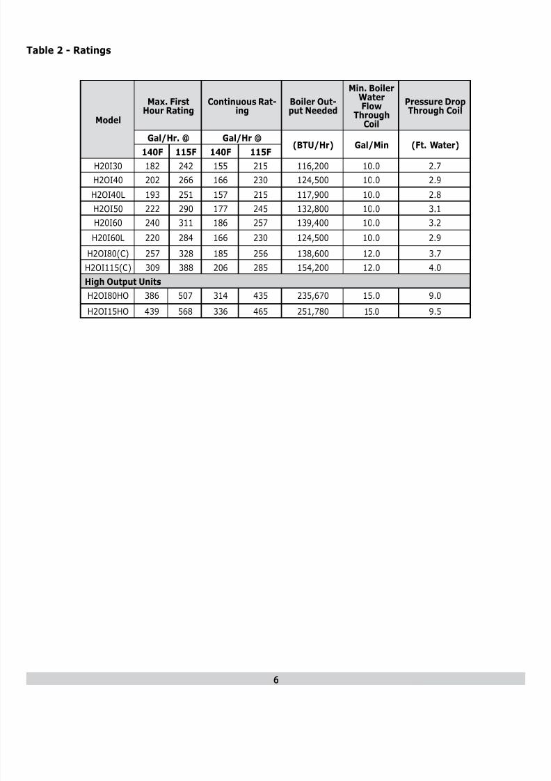
Model
Max. FirstHour Rating
Continuous Rat-ing
Boiler Out-put Needed
Min. BoilerWaterFlow
ThroughCoil
Pressure DropThrough Coil
Gal/Hr. @ Gal/Hr @(BTU/Hr) Gal/Min (Ft. Water)
140F 115F 140F 115F
H20I30 182 242 155 215 116,200 10.0 2.7
H2OI40 202 266 166 230 124,500 10.0 2.9
H2OI40L 193 251 157 215 117,900 10.0 2.8
H2OI50 222 290 177 245 132,800 10.0 3.1
H20I60 240 311 186 257 139,400 10.0 3.2
H20I60L 220 284 166 230 124,500 10.0 2.9
H2OI80(C) 257 328 185 256 138,600 12.0 3.7
H2OI115(C) 309 388 206 285 154,200 12.0 4.0
High Output Units
H2OI80HO 386 507 314 435 235,670 15.0 9.0
H2OI15HO 439 568 336 465 251,780 15.0 9.5
Table 2 - Ratings
7/21/2019 H2O Single Coil Indirect IOM Rev. B 812
http://slidepdf.com/reader/full/h2o-single-coil-indirect-iom-rev-b-812 7/24
7
3. Circulator Sizing.
Refer to Table 2 for the minimum ow through the water heater coil and the pressure drop at minimum ow. Calculate tpressure drop across all piping and ttings connected to the water heater zone. Be sure to include all zone valves, checkvalves, and shut-off valves. It is recommended that the water heater zone be piped with 1” pipe around the entire loop otypical residential sites.
A. System Zone Control
The water heater must be installed as a separate zone from the space heating system. The water heating zone’s pipingand circulator must be sized for the minimum ow rate with all the zones in use and a maximum ow with only the wateheater in use. Zone control with circulators normally gives the best performance.
The three most common systems are:
1. Zone Circulators - Space heating zones use a circulator for each zone. The water heater is controlled with anadditional circulator.
2. Hybrid System - Space heating zones use zone valves for each zone. The water heater is controlled with anadditional circulator.
3. Zone Valves - Space heating zones use zone valves for each zone. The water heater is controlled with anadditional zone valve. Select a valve with a low pressure drop, and assure minimum ow with adequate pipesizing.
B. Priority or Non-Priority for Hot Water
1. Option 1 – Priority. The demand for space heating is interrupted until the hot water demand is satised. Thisoption provides the maximum delivery of hot water.
Priority is recommended when:
A. The boiler output is less than 100,000 Btu per hour, or
B. The boiler output required to satisfy the hot water demand is more than 50% of the boiler output needed tosatisfy the space heating demand, or
C. When an interruption in space heating can be tolerated during long domestic hot water draws.
In most cases the delay in space heating will not be noticed because of the rapid recovery of the waterheater. It must be recognized however that certain water heater malfunctions, such as a failed thermostat ocirculator, could delay space heating indenitely.
2. Option 2 – Non-Priority. Boiler output is divided between space heating and water heating. Heating ofdomestic hot water can be reduced during simultaneous space and water heating demands. The amount ofreduction depends on boiler output, number of space heating zones calling, and the amount of boiler water ow
split between space heating and water heater zones.
7/21/2019 H2O Single Coil Indirect IOM Rev. B 812
http://slidepdf.com/reader/full/h2o-single-coil-indirect-iom-rev-b-812 8/24
8
C. Locating the water heater.
Water heater should be located in an area where water leakage from the tank or connections will not result in damage toareas adjacent to the water heater or to lower oors of the structure. When such a location can not be avoided, a suitabdrain pan must be installed under the water heater, and the drain pan must be connected to a drain.
Water heater should be installed as close to the boiler as is practical for easy access for service. Unit is designed for inst
lation on combustible ooring and in alcoves, closets, etc.
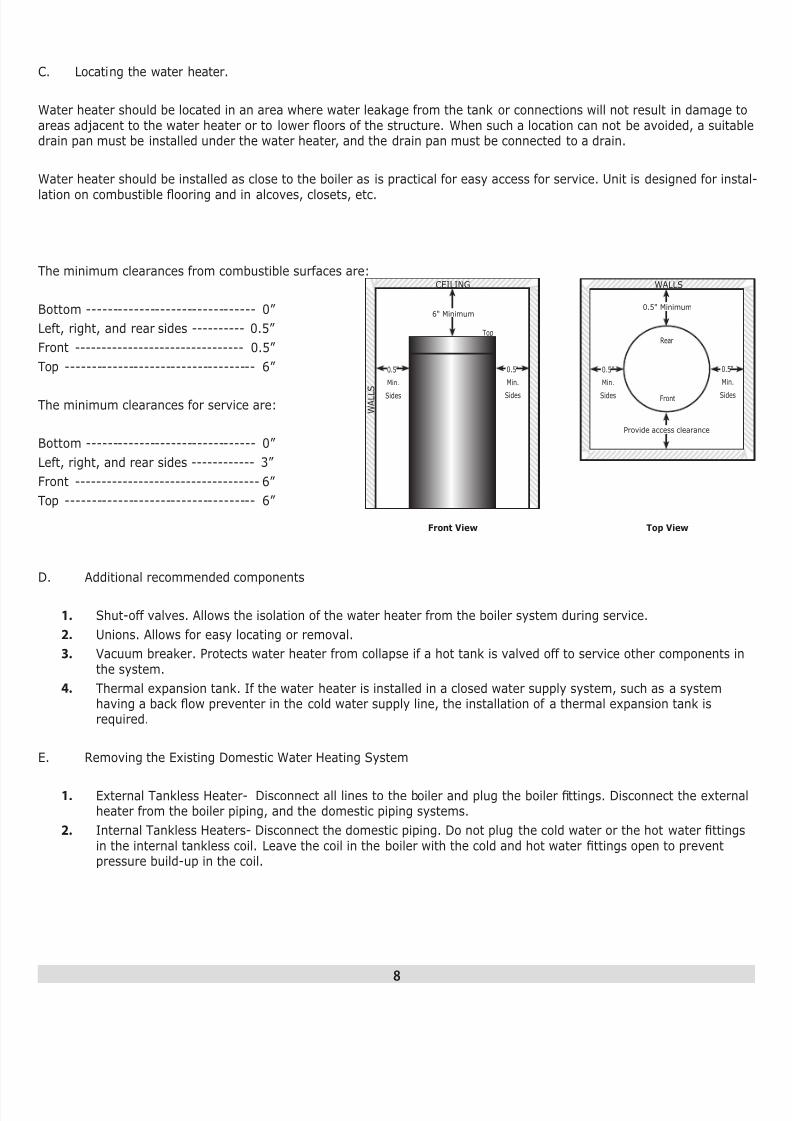
The minimum clearances from combustible surfaces are:
Bottom -------------------------------- 0”
Left, right, and rear sides ---------- 0.5”
Front -------------------------------- 0.5”
Top ------------------------------------ 6”
The minimum clearances for service are:
Bottom -------------------------------- 0”
Left, right, and rear sides ------------ 3”
Front ----------------------------------- 6”
Top ------------------------------------ 6”
D. Additional recommended components
1. Shut-off valves. Allows the isolation of the water heater from the boiler system during service.
2. Unions. Allows for easy locating or removal.
3. Vacuum breaker. Protects water heater from collapse if a hot tank is valved off to service other components inthe system.
4. Thermal expansion tank. If the water heater is installed in a closed water supply system, such as a systemhaving a back ow preventer in the cold water supply line, the installation of a thermal expansion tank isrequired.
E. Removing the Existing Domestic Water Heating System
1. External Tankless Heater- Disconnect all lines to the boiler and plug the boiler ttings. Disconnect the externaheater from the boiler piping, and the domestic piping systems.
2. Internal Tankless Heaters- Disconnect the domestic piping. Do not plug the cold water or the hot water ttingsin the internal tankless coil. Leave the coil in the boiler with the cold and hot water ttings open to preventpressure build-up in the coil.
WALLS
W A L L S
CEILING
6" Minimum0.5" Minimum
0.5"
Min.
Sides
0.5"
Min.
Sides
0.5"
Min.
Sides
0.5"
Min.
Sides
TopRear
Front
Provide access clearance
Front View Top View
7/21/2019 H2O Single Coil Indirect IOM Rev. B 812
http://slidepdf.com/reader/full/h2o-single-coil-indirect-iom-rev-b-812 9/24
9
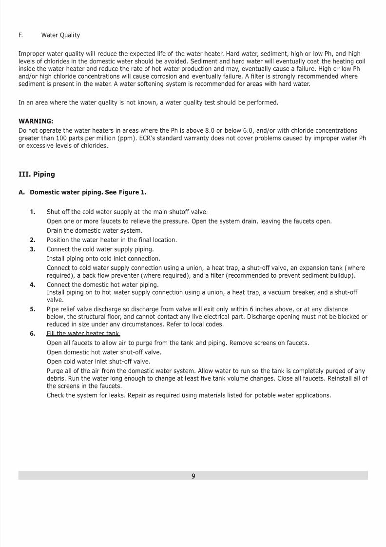
F. Water Quality
Improper water quality will reduce the expected life of the water heater. Hard water, sediment, high or low Ph, and highlevels of chlorides in the domestic water should be avoided. Sediment and hard water will eventually coat the heating coinside the water heater and reduce the rate of hot water production and may, eventually cause a failure. High or low Phand/or high chloride concentrations will cause corrosion and eventually failure. A lter is strongly recommended wheresediment is present in the water. A water softening system is recommended for areas with hard water.
In an area where the water quality is not known, a water quality test should be performed.
WARNING:
Do not operate the water heaters in areas where the Ph is above 8.0 or below 6.0, and/or with chloride concentrationsgreater than 100 parts per million (ppm). ECR’s standard warranty does not cover problems caused by improper water Por excessive levels of chlorides.
III. Piping
A. Domestic water piping. See Figure 1.
1. Shut off the cold water supply at the main shutoff valve.
Open one or more faucets to relieve the pressure. Open the system drain, leaving the faucets open.
Drain the domestic water system.
2. Position the water heater in the nal location.
3. Connect the cold water supply piping.
Install piping onto cold inlet connection.
Connect to cold water supply connection using a union, a heat trap, a shut-off valve, an expansion tank (whererequired), a back ow preventer (where required), and a lter (recommended to prevent sediment buildup).
4.Connect the domestic hot water piping. Install piping on to hot water supply connection using a union, a heat trap, a vacuum breaker, and a shut-offvalve.
5. Pipe relief valve discharge so discharge from valve will exit only within 6 inches above, or at any distancebelow, the structural oor, and cannot contact any live electrical part. Discharge opening must not be blocked oreduced in size under any circumstances. Refer to local codes.
6. Fill the water heater tank.
Open all faucets to allow air to purge from the tank and piping. Remove screens on faucets.
Open domestic hot water shut-off valve.
Open cold water inlet shut-off valve.
Purge all of the air from the domestic water system. Allow water to run so the tank is completely purged of andebris. Run the water long enough to change at least ve tank volume changes. Close all faucets. Reinstall all
the screens in the faucets.
Check the system for leaks. Repair as required using materials listed for potable water applications.
7/21/2019 H2O Single Coil Indirect IOM Rev. B 812
http://slidepdf.com/reader/full/h2o-single-coil-indirect-iom-rev-b-812 10/24
10
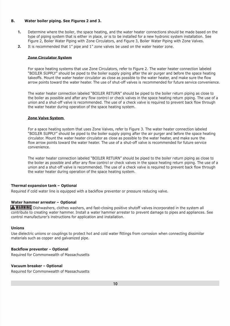
B. Water boiler piping. See Figures 2 and 3.
1. Determine where the boiler, the space heating, and the water heater connections should be made based on thtype of piping system that is either in place, or is to be installed for a new hydronic system installation. SeeFigure 2, Boiler Water Piping with Zone Circulators, and Figure 3, Boiler Water Piping with Zone Valves.
2. It is recommended that 1” pipe and 1” zone valves be used on the water heater zone.
Zone Circulator System
For space heating systems that use Zone Circulators, refer to Figure 2. The water heater connection labeled “BOILER SUPPLY” should be piped to the boiler supply piping after the air purger and before the space heatingtakeoffs. Mount the water heater circulator as close as possible to the water heater, and make sure the owarrow points toward the water heater. The use of shut-off valves is recommended for future service convenienc
The water heater connection labeled “BOILER RETURN” should be piped to the boiler return piping as close tothe boiler as possible and after any ow control or check valves in the space heating return piping. The use of union and a shut-off valve is recommended. The use of a check valve is required to prevent back ow throughthe water heater during operation of the space heating system.
Zone Valve System
For a space heating system that uses Zone Valves, refer to Figure 3. The water heater connection labeled “BOILER SUPPLY” should be piped to the boiler supply piping after the air purger and before the space heatingcirculator. Mount the water heater circulator as close as possible to the water heater, and make sure theow arrow points toward the water heater. The use of a shut-off valve is recommended for future serviceconvenience.
The water heater connection labeled “BOILER RETURN” should be piped to the boiler return piping as close tothe boiler as possible and after any ow control or check valves in the space heating return piping. The use of union and a shut-off valve is recommended. The use of a check valve is required to prevent back ow through
the water heater during operation of the space heating system.
Thermal expansion tank – Optional
Required if cold water line is equipped with a backow preventer or pressure reducing valve.
Water hammer arrester – Optional
Dishwashers, clothes washers, and fast-closing positive shutoff valves incorporated in the system allcontribute to creating water hammer. Install a water hammer arrester to prevent damage to pipes and appliances. Seecontrol manufacturer's instructions for application and installation.
UnionsUse dielectric unions or couplings to protect hot and cold water ttings from corrosion when connecting dissimilarmaterials such as copper and galvanized pipe.
Backow preventer – Optional
Required for Commonwealth of Massachusetts
Vacuum breaker – Optional
Required for Commonwealth of Massachusetts
7/21/2019 H2O Single Coil Indirect IOM Rev. B 812
http://slidepdf.com/reader/full/h2o-single-coil-indirect-iom-rev-b-812 11/24
11
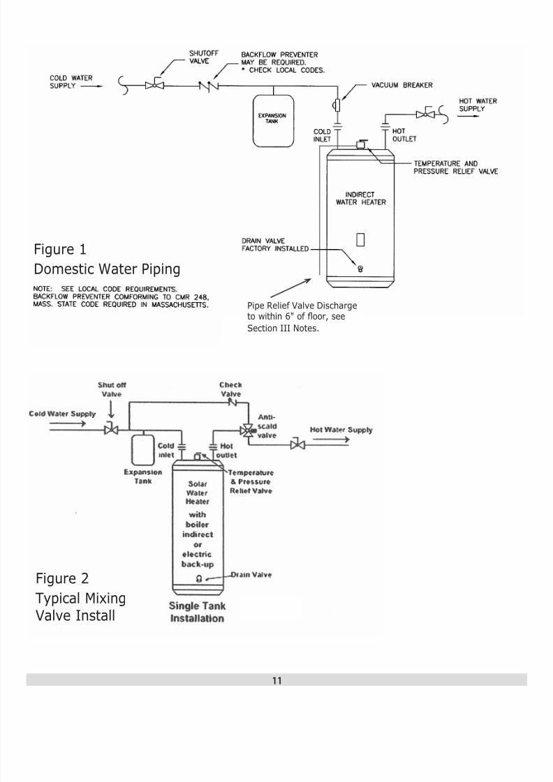
Figure 2
Typical MixingValve Install
Figure 1
Domestic Water Piping
Pipe Relief Valve Dischargeto within 6" of oor, see
Section III Notes.
7/21/2019 H2O Single Coil Indirect IOM Rev. B 812
http://slidepdf.com/reader/full/h2o-single-coil-indirect-iom-rev-b-812 12/24
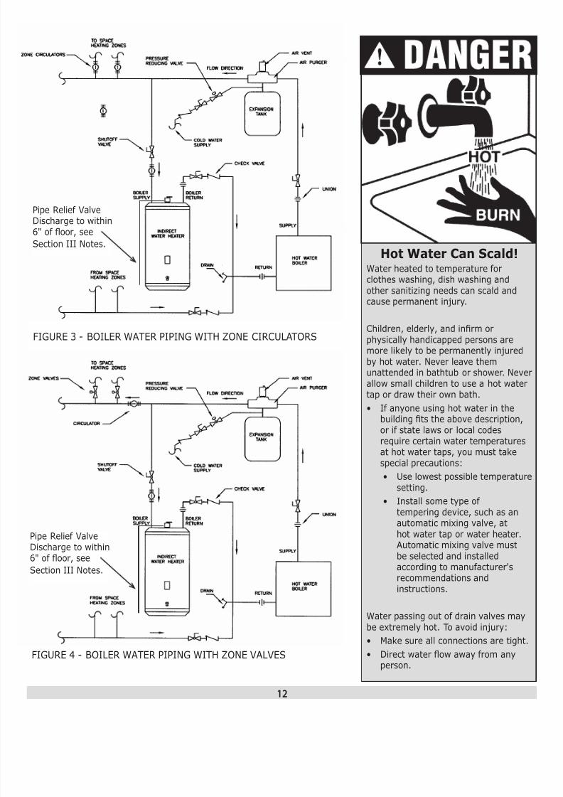
12
Hot Water Can Scald!Water heated to temperature for
clothes washing, dish washing andother sanitizing needs can scald andcause permanent injury.
Children, elderly, and inrm orphysically handicapped persons aremore likely to be permanently injuredby hot water. Never leave themunattended in bathtub or shower. Neveallow small children to use a hot watertap or draw their own bath.
• If anyone using hot water in the
building ts the above description,or if state laws or local codesrequire certain water temperaturesat hot water taps, you must takespecial precautions:
• Use lowest possible temperatursetting.
• Install some type oftempering device, such as anautomatic mixing valve, athot water tap or water heater.Automatic mixing valve must
be selected and installedaccording to manufacturer'srecommendations andinstructions.
Water passing out of drain valves maybe extremely hot. To avoid injury:
• Make sure all connections are tight.
• Direct water ow away from anyperson.
Pipe Relief ValveDischarge to within6" of oor, see
Section III Notes.
Pipe Relief ValveDischarge to within
6" of oor, seeSection III Notes.
FIGURE 4 - BOILER WATER PIPING WITH ZONE VALVES
FIGURE 3 - BOILER WATER PIPING WITH ZONE CIRCULATORS
7/21/2019 H2O Single Coil Indirect IOM Rev. B 812
http://slidepdf.com/reader/full/h2o-single-coil-indirect-iom-rev-b-812 13/24
13
IV. Electrical
1. Install electric wiring and grounding in accordance with the National Electrical code and local regulations.
2. All water heaters are supplied with a thermostat.
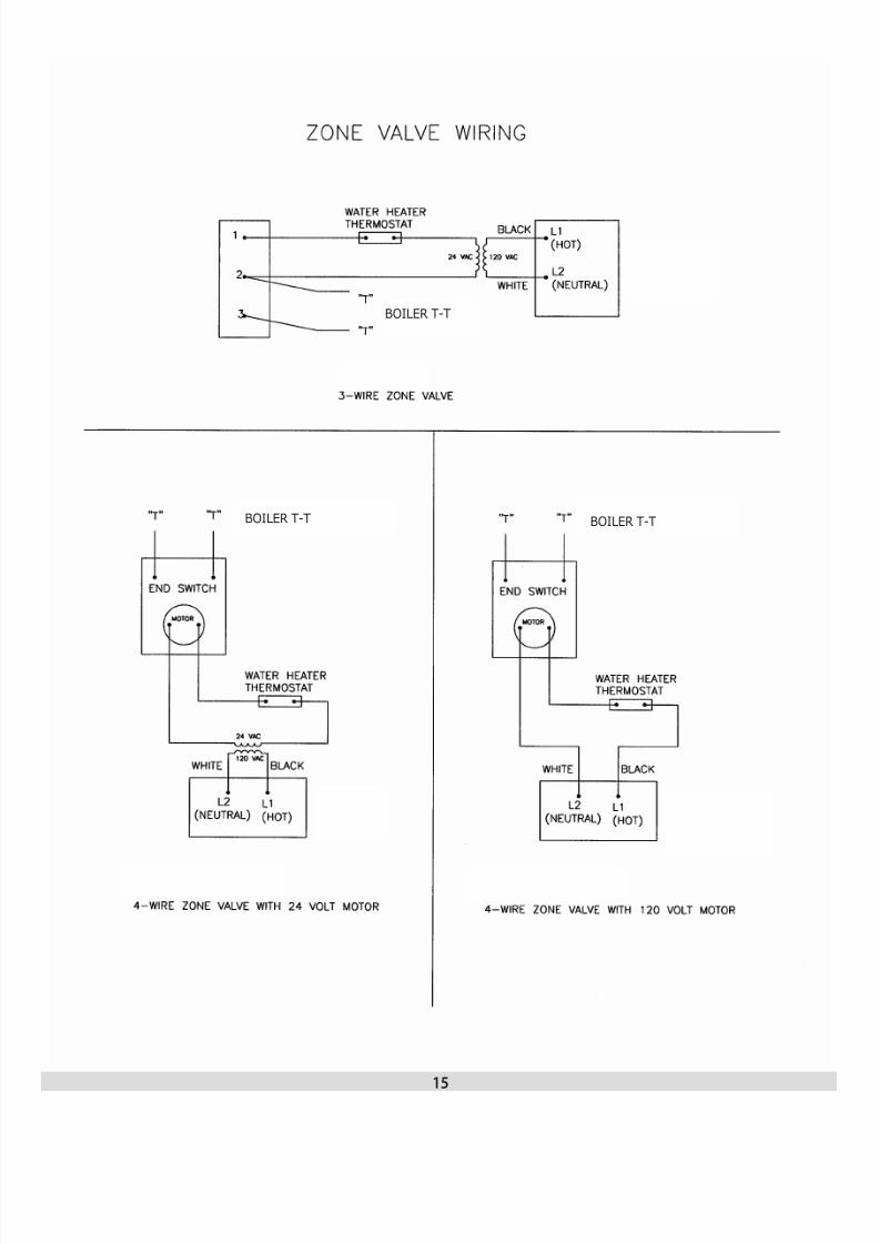
3. Refer to wiring schematics for separate circulator wiring.
Refer to wiring schematics for zone valve wiring.
Reference should be made to the Installation Manual for the boiler as well.
V. Operation
Startup
After the water heater has been plumbed and wired, and the boiler water piping is purged of air, the water heater is readto be started.
1. Follow boiler installation instructions to place boiler in operation.
2. The tank thermostat is factory pre-set to 125 degrees F and will call for heat if the water in the tank is lower
than 125.3. On a call for heat, the tank thermostat contacts close to start the water heater zone circulator and the boiler.
4. After the tank has reached the temperature setting, the tank thermostat opens and de-energizes the circulatorand the boiler. If there is a call for space heating, the boiler will continue to run until the room thermostats aresatised.
Temperature Adjustment
The tank thermostat controls the maximum water temperature in the water heater. If it is set too high, the resulting hotwater can cause painful scalding with possible serious and permanent injury. The temperature at which this occurs varieswith a person’s age, and the length of time in contact with the hot water. The slower response time of infants, older, or
handicapped people increases the hazard for them.It is recommended that the thermostat be set for the lowest possible temperature that satises your needs. This will alsoprovide you with the lowest energy consumption and cost.
Check the water temperature at a hot water faucet soon after the tank thermostat has satised, and the circulator and tboiler have turned off. Adjust as needed.
Lowering the thermostat setting will not have an immediate effect on the water temperature because the stored waterwill have to be used and the thermostat must go through the cycle of heating cold water and satisfying at the new, lowetemperature. Additional temperature checks should follow the completion of a heating cycle. Further adjustments may brequired after you have used the water heater.
Studies have indicated that dangerousbacteria including legionella pneumophila
can form in potable water distribution system if certain minimumwater temperatures are not maintained. Contact your local healthdepartment for more information.
7/21/2019 H2O Single Coil Indirect IOM Rev. B 812
http://slidepdf.com/reader/full/h2o-single-coil-indirect-iom-rev-b-812 14/24
14
Class 2
Terminals
Primary
Terminals
RE L A Y
RE L A Y
RE L A Y
RE L A Y
RE L A Y
RE L A Y
TO BOILER T-T
TERMINALS
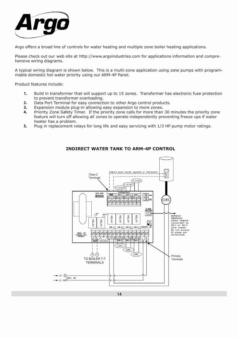
Argo offers a broad line of controls for water heating and multiple zone boiler heating applications.
Please check out our web site at http://www.argoindustries.com for applications information and compre-hensive wiring diagrams.
A typical wiring diagram is shown below. This is a multi-zone application using zone pumps with program-mable domestic hot water priority using our ARM-4P Panel.
Product features include:
Build in transformer that will support up to 15 zones. Transformer has electronic fuse protection1.
to prevent transformer overloading.Data Port Terminal for easy connection to other Argo control products.2.
Expansion module plug-in allowing easy expansion to more zones.3.
Priority Zone Safety Timer. If the priority zone calls for more than 30 minutes the priority zone4.
feature will turn off allowing all zones to operate independently preventing freeze ups if waterheater has a problem.Plug in replacement relays for long life and easy servicing with 1/3 HP pump motor ratings.5.
INDIRECT WATER TANK TO ARM-4P CONTROL
7/21/2019 H2O Single Coil Indirect IOM Rev. B 812
http://slidepdf.com/reader/full/h2o-single-coil-indirect-iom-rev-b-812 15/24
15
BOILER T-T
BOILER T-T BOILER T-T
7/21/2019 H2O Single Coil Indirect IOM Rev. B 812
http://slidepdf.com/reader/full/h2o-single-coil-indirect-iom-rev-b-812 16/24
16
VI. Maintenance
The water heater is intended to provide many years of reliable service. Components, such as thermostats and reliefvalves, may be subject to failures that require service. Depending on the quality of the water supply, sediment and/orscale may coat the heating coil in the tank and reduce hot water recovery rate. Failure to use the correct procedures orparts can result in unsafe operation.
The owner should arrange to have the following inspections and simple maintenance procedures done at the suggestedfrequencies.
1. Boiler and Domestic Water Piping (Annual)
Check all piping for signs of leakage at the joints, unions and shut-off valves. Repair as required.
2. Temperature and Pressure Relief Valve (Annual)
3. Sediment (Annual except where harsh water quality may require more frequent service)
Depending on water conditions, a varying amount of sediment may collect in the tank. Levels requiring serviceare indicated by a small temperature difference between the boiler supply and return lines, and a reducedrecovery rate. Repeated ushing usually clears such material. As a preventive measure, water should be drawnfrom the drain valve until it runs clear and the installation of a water lter should be considered.
4. Scale (Annual)
Hard water may cause scale buildup on the outside of the heating coil inside the tank. A water softener willprevent this problem. Symptoms are identical to sediment buildup. If repeated ushing does not resolve the
problem, chemical cleaning may be required. Contact a qualied contractor.
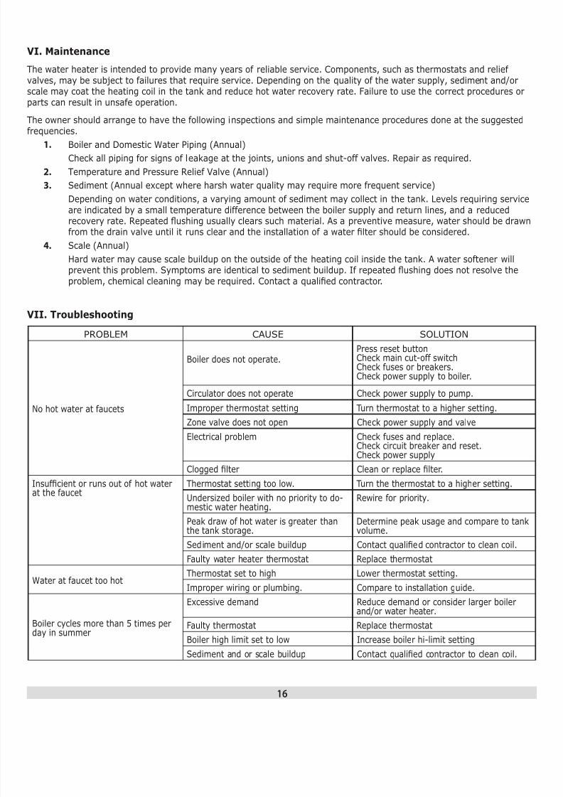
VII. Troubleshooting
PROBLEM CAUSE SOLUTION
No hot water at faucets
Boiler does not operate.Press reset buttonCheck main cut-off switchCheck fuses or breakers.Check power supply to boiler.
Circulator does not operate Check power supply to pump.
Improper thermostat setting Turn thermostat to a higher setting.
Zone valve does not open Check power supply and valve
Electrical problem Check fuses and replace.Check circuit breaker and reset.Check power supply
Clogged lter Clean or replace lter.
Insufcient or runs out of hot waterat the faucet
Thermostat setting too low. Turn the thermostat to a higher setting.
Undersized boiler with no priority to do-mestic water heating.
Rewire for priority.
Peak draw of hot water is greater thanthe tank storage.
Determine peak usage and compare to tankvolume.
Sediment and/or scale buildup Contact qualied contractor to clean coil.
Faulty water heater thermostat Replace thermostat
Water at faucet too hotThermostat set to high Lower thermostat setting.
Improper wiring or plumbing. Compare to installation guide.
Boiler cycles more than 5 times perday in summer
Excessive demand Reduce demand or consider larger boilerand/or water heater.
Faulty thermostat Replace thermostat
Boiler high limit set to low Increase boiler hi-limit setting
Sediment and or scale buildup Contact qualied contractor to clean coil.
7/21/2019 H2O Single Coil Indirect IOM Rev. B 812
http://slidepdf.com/reader/full/h2o-single-coil-indirect-iom-rev-b-812 17/24
17
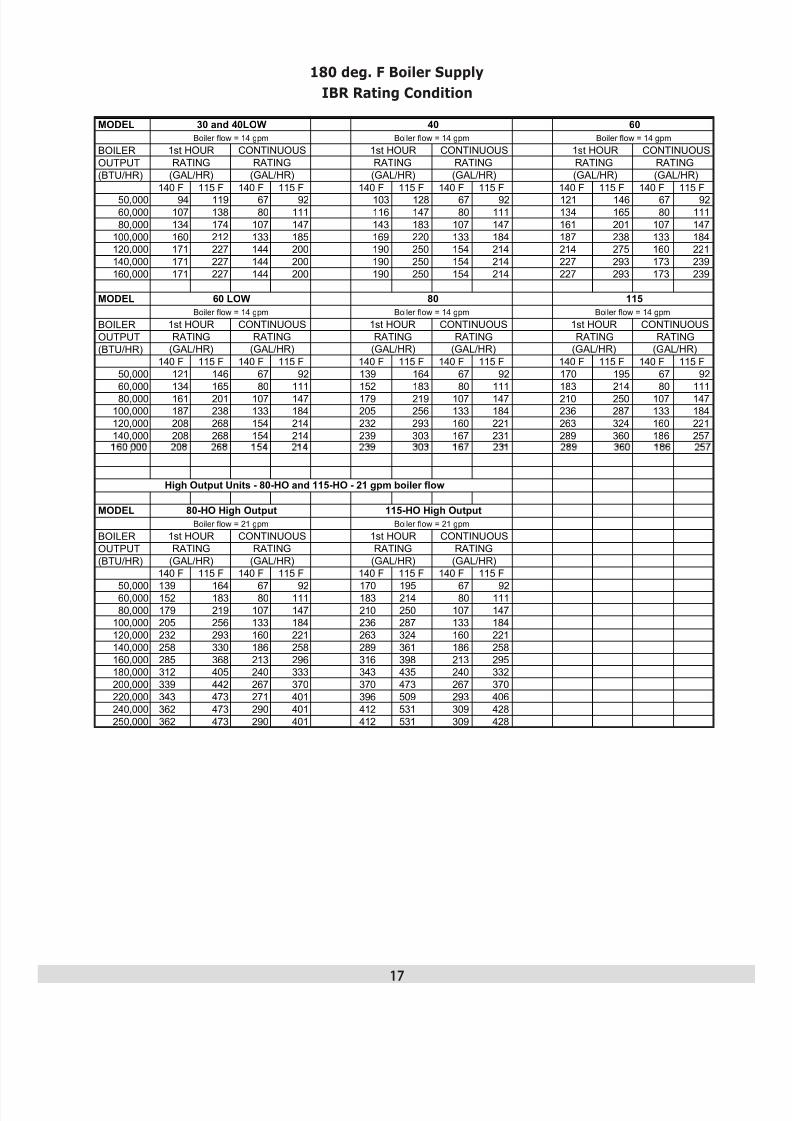
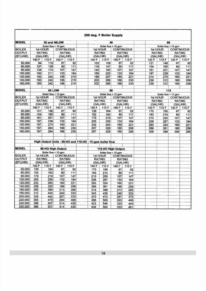
MODEL
BOILER
OUTPUT
(BTU/HR)
140 F 115 F 140 F 115 F 140 F 115 F 140 F 115 F 140 F 115 F 140 F 115 F
50,000 94 119 67 92 103 128 67 92 121 146 67 92
60,000 107 138 80 111 116 147 80 111 134 165 80 111
80,000 134 174 107 147 143 183 107 147 161 201 107 147
100,000 160 212 133 185 169 220 133 184 187 238 133 184
120,000 171 227 144 200 190 250 154 214 214 275 160 221
140,000 171 227 144 200 190 250 154 214 227 293 173 239
160,000 171 227 144 200 190 250 154 214 227 293 173 239
MODEL
BOILER
OUTPUT
(BTU/HR)
140 F 115 F 140 F 115 F 140 F 115 F 140 F 115 F 140 F 115 F 140 F 115 F
50,000 121 146 67 92 139 164 67 92 170 195 67 92
60,000 134 165 80 111 152 183 80 111 183 214 80 111
80,000 161 201 107 147 179 219 107 147 210 250 107 147
100,000 187 238 133 184 205 256 133 184 236 287 133 184
120,000 208 268 154 214 232 293 160 221 263 324 160 221
140,000 208 268 154 214 239 303 167 231 289 360 186 257
(GAL/HR)
1st HOUR CONTINUOUS
(GAL/HR) (GAL/HR)(GAL/HR) (GAL/HR) (GAL/HR)
RATING RATING RATING RATING RATING RATING
115
Boiler flow = 14 gpm Boiler flow = 14 gpm Boiler flow = 14 gpm
1st HOUR CONTINUOUS
60 LOW 80
1st HOUR CONTINUOUS
(GAL/HR) (GAL/HR) (GAL/HR) (GAL/HR) (GAL/HR) (GAL/HR)
RATING RATING
Boiler flow = 14 gpm Boiler flow = 14 gpm
RATING RATINGRATING RATING
1st HOUR CONTINUOUS 1st HOUR CONTINUOUS 1st HOUR CONTINUOUS
30 and 40LOW 40 60
Boiler flow = 14 gpm
,
MODEL
BOILER
OUTPUT
(BTU/HR)
140 F 115 F 140 F 115 F 140 F 115 F 140 F 115 F
50,000 139 164 67 92 170 195 67 9260,000 152 183 80 111 183 214 80 111
80,000 179 219 107 147 210 250 107 147
100,000 205 256 133 184 236 287 133 184
120,000 232 293 160 221 263 324 160 221
140,000 258 330 186 258 289 361 186 258
160,000 285 368 213 296 316 398 213 295
180,000 312 405 240 333 343 435 240 332
200,000 339 442 267 370 370 473 267 370
220,000 343 473 271 401 396 509 293 406
240,000 362 473 290 401 412 531 309 428
250,000 362 473 290 401 412 531 309 428
RATING RATING RATING RATING
(GAL/HR) (GAL/HR) (GAL/HR) (GAL/HR)
Boiler flow = 21 gpm Boiler flow = 21 gpm
1st HOUR CONTINUOUS 1st HOUR CONTINUOUS
High Output Units - 80-HO and 115-HO - 21 gpm boiler flow
80-HO High Output 115-HO High Output
180 deg. F Boiler Supply
IBR Rating Condition
7/21/2019 H2O Single Coil Indirect IOM Rev. B 812
http://slidepdf.com/reader/full/h2o-single-coil-indirect-iom-rev-b-812 18/24
18
7/21/2019 H2O Single Coil Indirect IOM Rev. B 812
http://slidepdf.com/reader/full/h2o-single-coil-indirect-iom-rev-b-812 19/24
19
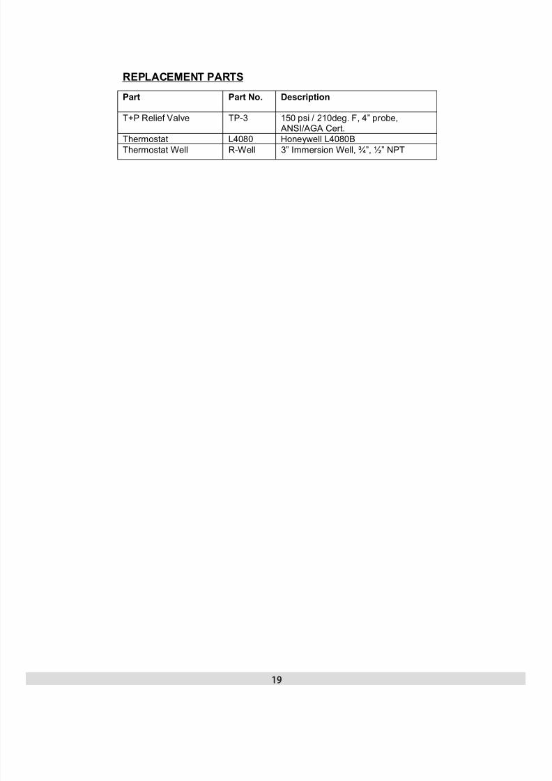
REPLACEMENT PARTS
Part Part No. Description List Price
T+P Relief Valve TP-3 150 psi / 210deg. F, 4” probe, ANSI/AGA Cert.
Thermostat L4080 Honeywell L4080B 59.63Thermostat Well R-Well 3” Immersion Well, ¾”, ½” NPT 40.94
7/21/2019 H2O Single Coil Indirect IOM Rev. B 812
http://slidepdf.com/reader/full/h2o-single-coil-indirect-iom-rev-b-812 20/24
20
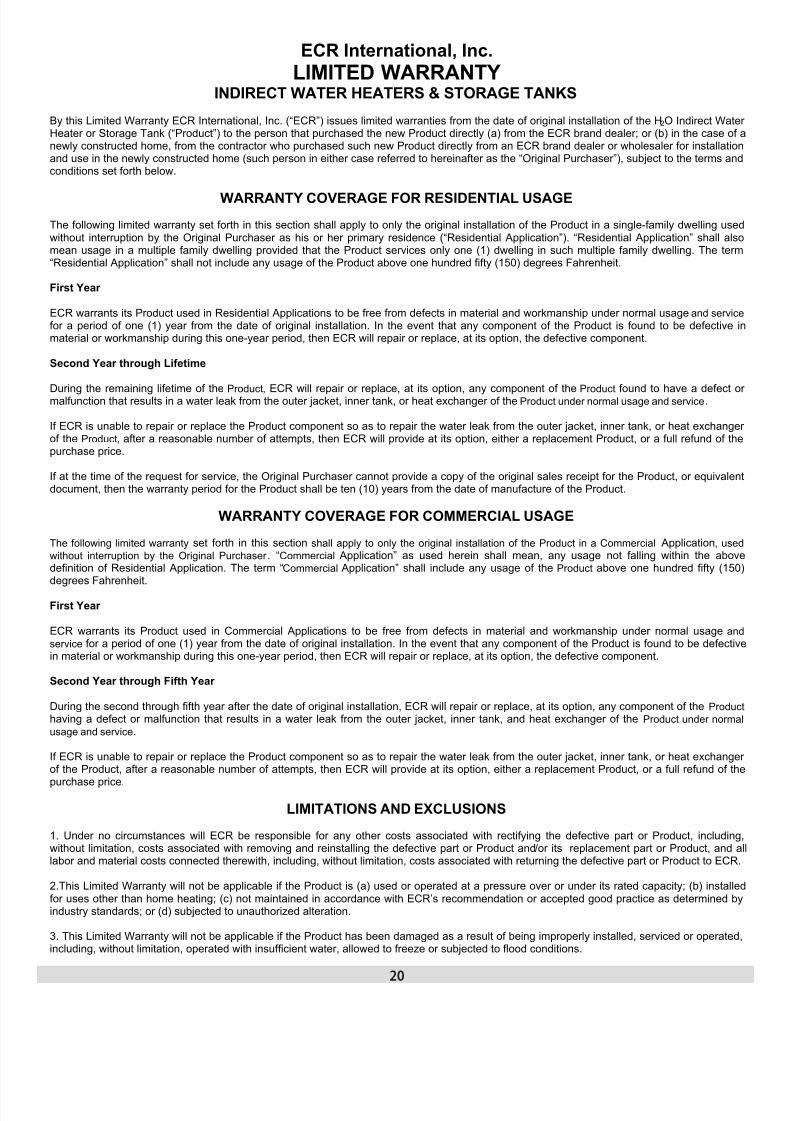
ECR International, Inc.
LIMITED WARRANTYINDIRECT WATER HEATERS & STORAGE TANKS
By this Limited Warranty ECR International, Inc. (“ECR”) issues limited warranties from the date of original installation of the H2O Indirect WateHeater or Storage Tank (“Product”) to the person that purchased the new Product directly (a) from the ECR brand dealer; or (b) in the case of anewly constructed home, from the contractor who purchased such new Product directly from an ECR brand dealer or wholesaler for installationand use in the newly constructed home (such person in either case referred to hereinafter as the “Original Purchaser”), subject to the terms andconditions set forth below.
WARRANTY COVERAGE FOR RESIDENTIAL USAGE
The following limited warranty set forth in this section shall apply to only the original installation of the Product in a single-family dwelling usedwithout interruption by the Original Purchaser as his or her primary residence (“Residential Application”). “Residential Application” shall alsomean usage in a multiple family dwelling provided that the Product services only one (1) dwelling in such multiple family dwelling. The term“Residential Application” shall not include any usage of the Product above one hundred fifty (150) degrees Fahrenheit.
First Year
ECR warrants its Product used in Residential Applications to be free from defects in material and workmanship under normal usage and service
for a period of one (1) year from the date of original installation. In the event that any component of the Product is found to be defective inmaterial or workmanship during this one-year period, then ECR will repair or replace, at its option, the defective component.
Second Year through Lifetime
During the remaining lifetime of the Product, ECR will repair or replace, at its option, any component of the Product found to have a defect omalfunction that results in a water leak from the outer jacket, inner tank, or heat exchanger of the Product under normal usage and service.
If ECR is unable to repair or replace the Product component so as to repair the water leak from the outer jacket, inner tank, or heat exchangerof the Product, after a reasonable number of attempts, then ECR will provide at its option, either a replacement Product, or a full refund of thepurchase price.
If at the time of the request for service, the Original Purchaser cannot provide a copy of the original sales receipt for the Product, or equivalentdocument, then the warranty period for the Product shall be ten (10) years from the date of manufacture of the Product.
WARRANTY COVERAGE FOR COMMERCIAL USAGE
The following limited warranty set forth in this section shall apply to only the original installation of the Product in a Commercial Application, used
without interruption by the Original Purchaser . “Commercial Application” as used herein shall mean, any usage not falling within the abovedefinition of Residential Application. The term “Commercial Application” shall include any usage of the Product above one hundred fifty (150degrees Fahrenheit.
First Year
ECR warrants its Product used in Commercial Applications to be free from defects in material and workmanship under normal usage and
service for a period of one (1) year from the date of original installation. In the event that any component of the Product is found to be defectivein material or workmanship during this one-year period, then ECR will repair or replace, at its option, the defective component.
Second Year through Fifth Year
During the second through fifth year after the date of original installation, ECR will repair or replace, at its option, any component of the Produc
having a defect or malfunction that results in a water leak from the outer jacket, inner tank, and heat exchanger of the Product under norma
usage and service.
If ECR is unable to repair or replace the Product component so as to repair the water leak from the outer jacket, inner tank, or heat exchangerof the Product, after a reasonable number of attempts, then ECR will provide at its option, either a replacement Product, or a full refund of the
purchase price.
LIMITATIONS AND EXCLUSIONS
1. Under no circumstances will ECR be responsible for any other costs associated with rectifying the defective part or Product, including,without limitation, costs associated with removing and reinstalling the defective part or Product and/or its replacement part or Product, and alabor and material costs connected therewith, including, without limitation, costs associated with returning the defective part or Product to ECR.
2.This Limited Warranty will not be applicable if the Product is (a) used or operated at a pressure over or under its rated capacity; (b) installedfor uses other than home heating; (c) not maintained in accordance with ECR’s recommendation or accepted good practice as determined byindustry standards; or (d) subjected to unauthorized alteration.
3. This Limited Warranty will not be applicable if the Product has been damaged as a result of being improperly installed, serviced or operated,including, without limitation, operated with insufficient water, allowed to freeze or subjected to flood conditions.
7/21/2019 H2O Single Coil Indirect IOM Rev. B 812
http://slidepdf.com/reader/full/h2o-single-coil-indirect-iom-rev-b-812 21/24
21
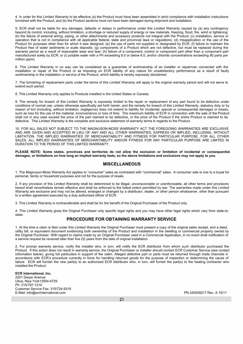
4. In order for this Limited Warranty to be effective (a) the Product must have been assembled in strict compliance with installation instructionsfurnished with the Product; and (b) the Product sections must not have been damaged during shipment and installation.
5. ECR shall not be liable for any damages, defaults or delays in performance under this Limited Warranty caused by (a) any contingencybeyond its control, including, without limitation, a shortage or reduced supply of energy or raw materials, freezing, flood, fire, wind or lightening;(b) the failure of external wiring, piping, or other attachments and accessory products not integral with the Product; (c) installation, service oroperation that is not in compliance with all applicable federal, state and provincial laws or regulations; (d) misapplication or the use of theProduct for purposes other than for which it was designed; (e) the use of parts not supplied or designated by ECR; (f) failure to maintain theProduct free of water sediments or scale deposits; (g) components of a Product which are not defective, but must be replaced during thewarranty period as a result of reasonable wear and tear; (h) failure of a component, control or component part other than a component partmanufactured solely by ECR; or (i) potable water with a Ph exceeding 8.0 or below 6.0, and/or chloride concentrations exceeding 80 parts per
million (ppm).
6. This Limited Warranty in no way can be considered as a guarantee of workmanship of an installer or repairman connected with theinstallation or repair of the Product or as imposing on ECR liability of any nature for unsatisfactory performance as a result of faultyworkmanship in the installation or service of the Product, which liability is hereby expressly disclaimed.
7. The furnishing of replacement parts under the terms of this Limited Warranty will apply to the original warranty period and will not serve toextend such period.
8. This Limited Warranty only applies to Products installed in the United States or Canada.
9. The remedy for breach of this Limited Warranty is expressly limited to the repair or replacement of any part found to be defective undeconditions of normal use, unless otherwise specifically set forth herein, and the remedy for breach of this Limited Warranty, statutory duty or byreason of tort (including, without limitation, negligence) does not extend to liability for incidental, special or consequential damages or lossessuch as loss for the use of the material, inconvenience or loss of time. The maximum liability of ECR in connection with the sale of the Producshall not in any case exceed the price of the part claimed to be defective, or the price of the Product if the entire Product is claimed to be
defective. This Limited Warranty is the complete and exclusive statement of warranty terms in regards to the Product.
10. FOR ALL SALES NOT SUBJECT TO THE MAGNUSON-MOSS WARRANTY ACT THE FOREGOING WARRANTIES ARE EXCLUSIVE AND ARE GIVEN AND ACCEPTED IN LIEU OF ANY AND ALL OTHER WARRANTIES, EXPRESS OR IMPLIED, INCLUDING, WITHOUTLIMITATION, THE IMPLIED WARRANTIES OF MERCHANTABILITY AND FITNESS FOR PARTICULAR PURPOSE. FOR ALL OTHERSALES, ALL IMPLIED WARRANTIES OF MERCHANTABILITY AND/OR FITNESS FOR ANY PARTICULAR PURPOSE ARE LIMITED INDURATION TO THE PERIOD OF THIS LIMITED WARRANTY.
PLEASE NOTE: Some states, provinces and territories do not allow the exclusion or limitation of incidental or consequentidamages, or limitations on how long an implied warranty lasts, so the above limitations and exclusions may not apply to you.
MISCELLANEOUS
1. The Magnuson-Moss Warranty Act applies to “consumer” sales as contrasted with “commercial” sales. A consumer sale is one to a buyer fopersonal, family or household purposes and not for the purpose of resale.
2. If any provision of this Limited Warranty shall be determined to be illegal, unconscionable or unenforceable, all other terms and provisionshereof shall nevertheless remain effective and shall be enforced to the fullest extent permitted by law. The warranties made under this LimitedWarranty are exclusive and may not be altered, enlarged or changed by a distributor, dealer, or other person whatsoever, other than pursuanto a written agreement executed by a duly authorized officer of ECR.
3. This Limited Warranty is nontransferable and shall be for the benefit of the Original Purchaser of the Product only.
4. This Limited Warranty gives the Original Purchaser only specific legal rights and you may have other legal rights which vary from state-tostate.
PROCEDURE FOR OBTAINING WARRANTY SERVICE
1. At the time a claim is filed under this Limited Warranty the Original Purchaser must present a copy of the original sales receipt, and a deed,utility bill, or equivalent document evidencing both ownership of the Product and installation in the dwelling or commercial property owned bythe Original Purchaser. With regard to claims made by an Original Purchaser used in a Commercial Application, in no event shall notification ofa service request be received later than five (5) years from the date of original installation.
2. For prompt warranty service, notify the installer who, in turn, will notify the ECR distributor from whom such distributor purchased theProduct. If this action does not result in warranty service, the Original Purchaser or installer should contact ECR Customer Service (see contacinformation below), giving full particulars in support of the claim. Alleged defective part or parts must be returned through trade channels inaccordance with ECR’s procedure currently in force for handling returned goods for the purpose of inspection or determining the cause offailure. ECR will furnish the new part(s) to an authorized ECR distributor who, in turn, will furnish the part(s) to the heating contractor whoinstalled the Product.
ECR International, Inc.2201 Dwyer AvenueUtica, New York13504-4729Ph: 315/797-1310Customer Service Fax: 315/724-9319E-Mail: [email protected] PN 240009217 Rev. A 10/11

7/21/2019 H2O Single Coil Indirect IOM Rev. B 812
http://slidepdf.com/reader/full/h2o-single-coil-indirect-iom-rev-b-812 22/24
22
NOTES

7/21/2019 H2O Single Coil Indirect IOM Rev. B 812
http://slidepdf.com/reader/full/h2o-single-coil-indirect-iom-rev-b-812 23/24
23
NOTES

7/21/2019 H2O Single Coil Indirect IOM Rev. B 812
http://slidepdf.com/reader/full/h2o-single-coil-indirect-iom-rev-b-812 24/24
ECR International, Inc2201 Dwyer Avenue, Utica NY 13504-4729
web site: www.ecrinternational.com
H2O


![Central Metabolism Cofactor Biosynthesis · ppp9 pi h h2o ppi h h2o h2o dad-5 h[p] atp adp h pi h2o succoa lipoate atp glx 2p4c2me xu5p-D h2o cbl1 ppi h[e] h2o h dad-5 gthrd asp-L](https://img.pdfslide.net/doc/110x75/5f47678d7025ea6bb340bf3d/central-metabolism-cofactor-biosynthesis-ppp9-pi-h-h2o-ppi-h-h2o-h2o-dad-5-hp.jpg)