Embed Size (px)
Citation preview

15-601046 Issue 17e - (Wednesday November 14 2012)
H323 Telephone Installation
IP Office
H323 Telephone Installation Page 215-601046 Issue 17e (Wednesday November 14 2012)IP Office
copy 2012 AVAYA All Rights Reserved
NoticesWhile reasonable efforts have been made to ensure that the information inthis document is complete and accurate at the time of printing Avaya assumesno liability for any errors Avaya reserves the right to make changes andcorrections to the information in this document without the obligation to notifyany person or organization of such changes
Documentation disclaimerAvaya shall not be responsible for any modifications additions or deletions tothe original published version of this documentation unless such modificationsadditions or deletions were performed by Avaya
End User agree to indemnify and hold harmless Avaya Avayas agentsservants and employees against all claims lawsuits demands and judgmentsarising out of or in connection with subsequent modifications additions ordeletions to this documentation to the extent made by End User
Link disclaimerAvaya is not responsible for the contents or reliability of any linked Web sitesreferenced within this site or documentation(s) provided by Avaya Avaya isnot responsible for the accuracy of any information statement or contentprovided on these sites and does not necessarily endorse the productsservices or information described or offered within them Avaya does notguarantee that these links will work all the time and has no control over theavailability of the linked pages
WarrantyAvaya provides a limited warranty on this product Refer to your salesagreement to establish the terms of the limited warranty In addition Avayarsquosstandard warranty language as well as information regarding support for thisproduct while under warranty is available to Avaya customers and otherparties through the Avaya Support Web site httpwwwavayacomsupportPlease note that if you acquired the product from an authorized Avaya reselleroutside of the United States and Canada the warranty is provided to you bysaid Avaya reseller and not by Avaya
LicensesTHE SOFTWARE LICENSE TERMS AVAILABLE ON THE AVAYA WEBSITEHTTPSUPPORTAVAYACOMLICENSEINFO ARE APPLICABLE TO ANYONEWHO DOWNLOADS USES ANDOR INSTALLS AVAYA SOFTWARE PURCHASEDFROM AVAYA INC ANY AVAYA AFFILIATE OR AN AUTHORIZED AVAYARESELLER (AS APPLICABLE) UNDER A COMMERCIAL AGREEMENT WITHAVAYA OR AN AUTHORIZED AVAYA RESELLER UNLESS OTHERWISE AGREEDTO BY AVAYA IN WRITING AVAYA DOES NOT EXTEND THIS LICENSE IF THESOFTWARE WAS OBTAINED FROM ANYONE OTHER THAN AVAYA AN AVAYAAFFILIATE OR AN AVAYA AUTHORIZED RESELLER AND AVAYA RESERVESTHE RIGHT TO TAKE LEGAL ACTION AGAINST YOU AND ANYONE ELSE USINGOR SELLING THE SOFTWARE WITHOUT A LICENSE BY INSTALLINGDOWNLOADING OR USING THE SOFTWARE OR AUTHORIZING OTHERS TODO SO YOU ON BEHALF OF YOURSELF AND THE ENTITY FOR WHOM YOUARE INSTALLING DOWNLOADING OR USING THE SOFTWARE (HEREINAFTERREFERRED TO INTERCHANGEABLY AS ldquoYOUrdquo AND ldquoEND USERrdquo) AGREE TOTHESE TERMS AND CONDITIONS AND CREATE A BINDING CONTRACTBETWEEN YOU AND AVAYA INC OR THE APPLICABLE AVAYA AFFILIATE(ldquoAVAYArdquo)
Avaya grants End User a license within the scope of the license types describedbelow The applicable number of licenses and units of capacity for which thelicense is granted will be one (1) unless a different number of licenses or unitsof capacity is specified in the Documentation or other materials available toEnd User Designated Processor means a single stand-alone computingdevice Server means a Designated Processor that hosts a softwareapplication to be accessed by multiple users Software means the computerprograms in object code originally licensed by Avaya and ultimately utilized byEnd User whether as stand-alone products or pre-installed on HardwareHardware means the standard hardware originally sold by Avaya andultimately utilized by End User
License typesDesignated System(s) License (DS) End User may install and use each copy ofthe Software on only one Designated Processor unless a different number ofDesignated Processors is indicated in the Documentation or other materialsavailable to End User Avaya may require the Designated Processor(s) to beidentified by type serial number feature key location or other specificdesignation or to be provided by End User to Avaya through electronic meansestablished by Avaya specifically for this purpose
CopyrightExcept where expressly stated otherwise no use should be made of materialson this site the Documentation(s) and Product(s) provided by Avaya Allcontent on this site the documentation(s) and the product(s) provided byAvaya including the selection arrangement and design of the content is ownedeither by Avaya or its licensors and is protected by copyright and otherintellectual property laws including the sui generis rights relating to theprotection of databases You may not modify copy reproduce republishupload post transmit or distribute in any way any content in whole or in partincluding any code and software Unauthorized reproduction transmissiondissemination storage and or use without the express written consent ofAvaya can be a criminal as well as a civil offense under the applicable law
Third Party Components Certain software programs or portions thereof included in the Product maycontain software distributed under third party agreements (Third PartyComponents) which may contain terms that expand or limit rights to usecertain portions of the Product (Third Party Terms) Information regardingdistributed Linux OS source code (for those Products that have distributed theLinux OS source code) and identifying the copyright holders of the Third PartyComponents and the Third Party Terms that apply to them is available on theAvaya Support Web site httpsupportavayacomCopyright
Preventing toll fraudToll fraud is the unauthorized use of your telecommunications system by anunauthorized party (for example a person who is not a corporate employeeagent subcontractor or is not working on your companys behalf) Be awarethat there can be a risk of toll fraud associated with your system and that iftoll fraud occurs it can result in substantial additional charges for yourtelecommunications services
Avaya fraud interventionIf you suspect that you are being victimized by toll fraud and you needtechnical assistance or support call Technical Service Center Toll FraudIntervention Hotline at +1-800-643-2353 for the United States and CanadaFor additional support telephone numbers see the Avaya Support Web sitehttpsupportavayacomSuspected security vulnerabilities with Avaya products should be reported toAvaya by sending mail to securityalertsavayacom
TrademarksAvaya and Aura are trademarks of Avaya IncThe trademarks logos and service marks (ldquoMarksrdquo) displayed in this site thedocumentation(s) and product(s) provided by Avaya are the registered orunregistered Marks of Avaya its affiliates or other third parties Users are notpermitted to use such Marks without prior written consent from Avaya or suchthird party which may own the Mark Nothing contained in this site thedocumentation(s) and product(s) should be construed as granting byimplication estoppel or otherwise any license or right in and to the Markswithout the express written permission of Avaya or the applicable third partyAvaya is a registered trademark of Avaya Inc All non-Avaya trademarks arethe property of their respective owners
Downloading documentsFor the most current versions of documentation see the Avaya Support Website httpwwwavayacomsupport
Contact Avaya SupportAvaya provides a telephone number for you to use to report problems or toask questions about your product The support telephone number is1-800-242-2121 in the United States For additional support telephonenumbers see the Avaya Web site httpwwwavayacomsupport
H323 Telephone Installation Page 315-601046 Issue 17e (Wednesday November 14 2012)IP Office
Contents
ContentsIP Office H323 IP Phones1
811 Supported Phones
912 System Capacity
1013 Phone Firmware
1114 Simple Installation
1215 Installation Requirements
1316 Licenses
1417 Network Assessment
1518 Voice Compression Channels
1719 QoS
17110 Potential VoIP Problems
18111 User PC Connection
19112 Power Supply Options
21113 File Server Options
22114 File Auto-Generation
22115 Control Unit Memory Card
Installation2 2521 Licensing
25211 Checking the Serial Number
26212 Adding Licenses
26213 Reserving Licenses
2722 System H323 Support
27221 Enabling the H323 Gatekeeper
28222 Setting the RTP Port Range
29223 Enabling RTCP Quality Monitoring
31224 Adjusting DiffServ QoS
32225 System Default Codecs
3323 DHCP Settings
35231 System DHCP Support
36232 System Site Specific Option Numbers
3724 File Server Settings
38241 System File Server Settings
39242 CreatingEditing the Settings File
41243 Loading Software Files onto the System
44244 Loading Files onto a 3rd Party Server
4525 User and Extension Creation
45251 Auto-Creation
46252 Manually Creating User
46253 Manually Creating Extensions
4826 Phone Connection
4927 Static Address Installation
5128 Phone Registration
5229 BackupRestore Settings
53291 Example File
54292 IIS Server Configuration
54293 Apache Server Configuration
55210 Listing Registered Phones
55211 Other Installation Options
552111 VPN Remote Phones
592112 VLAN and IP Phones
Static Administration Options3
6731 Secondary Ethernet (Hub)IR InterfaceEnableDisable
6832 View Details
7033 Self-Test Procedure
7134 Resetting a Phone
7135 Clearing a Phone
7136 Site Specific Option Number
Restart Scenarios4 7741 Boot File Needs Upgrading
7742 No Application File or Application File NeedsUpgrading
7743 Correct Boot File and Application File AlreadyLoaded
Infrared Dialing5 8151 Enabling the IR Port
8152 Dialing Phone Numbers
8253 Beaming Files During a Call
Alternate DHCP Server Setup6 8561 Alternate Options
8662 Checking for DHCP Server Support
8663 Creating a Scope
8664 Adding a 242 Option
8765 Adding a 176 Option
8966 Activating the Scope
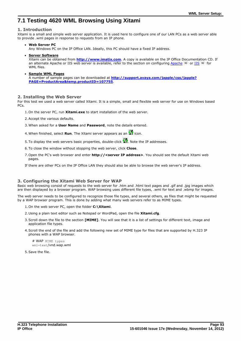
WML Server Setup7 9371 Testing 4620 WML Browsing Using Xitami
9572 Setting the Home Page
9673 Apache Web Server WML Configuration
9674 Microsoft IIS Web Server WML Configuration
9775 Open URL Entry
99Index
H323 Telephone Installation Page 515-601046 Issue 17e (Wednesday November 14 2012)IP Office
IP Office H323 IP Phones
Chapter 1
H323 Telephone Installation Page 715-601046 Issue 17e (Wednesday November 14 2012)IP Office
IP Office H323 IP Phones
1 IP Office H323 IP PhonesThis documentation provides notes for the installation of supported Avaya IP phones onto an IP Office system Itshould be used in conjunction with the existing installation documentation for those series of phones especially thefollowing
middot 9600 Series IP Telephones Administrator Guide (16-300698)
middot 96x1 Series IP Telephones Administrator Guide (16-300699)
middot 1600 Series IP Telephones Administrators Guide (16-601443)
middot 4600 Series IP Telephone LAN Administrator Guide (555-233-507)
middot DHCP versus Static IP InstallationThough static IP installation of H323 IP phones is possible installation using DHCP is strongly recommended Theuse of DHCP eases both the installation process and future maintenance and administration For static installationsfollowing a boot file upgrade all static address settings are lost and must be re-entered
middot Network AssessmentHigh quality voice transmission across an IP network requires careful assessment of many factors Therefore
middot We strongly recommend that IP phone installation is only done by installers with VoIP experience
middot The whole customer network must be assessed for its suitability for VoIP before installation Avaya mayrefuse to support any installation where the results of a network assessment cannot be supplied See NetworkAssessment for further details
8
14
H323 Telephone Installation Page 815-601046 Issue 17e (Wednesday November 14 2012)IP Office
11 Supported PhonesThis documentation provides installation notes for the following Avaya IP phones supported by IP Office Other supportedAvaya H323 IP phones for example DECT R4 3700 Series phones are covered by separate installation documentation
H323 IPPhones
SupportedModels
8023af PoEClass
PC Port IP OfficeCoreSoftware
Class Idle
1600Series
1603 2 44W ndash 42 Q4 2008+
1603SW 2 44W
1608 2 37W
1616 2 27W
4600Series
4601 2 35W ndash 30+
4602 1 ndash ndash 21+
4602SW 2 35W
4606 0 41W Up to 32
4610SW[1] 2 40W 30+
4612 0 41W Up to 32
4620 3 40W ndash 20+
4620SW 2 ndash
4621SW[1] 2 575W 30+
4624 0 41W Up to 32
4625 3 645W 32+
5600Series
5601 2 35W ndash 30+
5602 1 ndash ndash
5602SW 2 41W
5610SW[1] 2 31W
5620 3 36W
5621SW[1] 2 ndash 32+
9600Series
9620L 1 20W 60+
9620C 2 39W
9630G 2 46W
9640 2 39W
9640G 2 39W
9650 2 47W
9650C 2 37W
9608 1 208W 80+
9611G 1 28W
9621G 2 349W
9641G 2 344W
1VPNremote Support These phones can also be used with VPNremote firmware
216031603SW These phones require a PoE Splitter unit in order to use PoE
H323 Telephone Installation Page 915-601046 Issue 17e (Wednesday November 14 2012)IP Office
IP Office H323 IP Phones Supported Phones
12 System CapacitySystem capacity encompasses the number of configurable phone extensions and the number of simultaneous IP phonecalls
Extension CapacityThe maximum number of H323 IP phones supported by an IP Office system is based on that systems maximumcapacity for extensions of any type as listed in the table below To find the capacity for IP phones subtract the number ofphysical non-IP extensions installed on the system ie extension ports on the IP Office control unit and any externalexpansion modules
IP Office Unit MaximumExtensions
Maximum VCM Channels
IP500 384 128
IP500 V2 384 148
Call CapacityThere are a number of situations where the IP Office system needs to provide a voice compression channel in order foran IP phone to make calls These channels are provided by Voice Compression Modules (VCMs) installed in the IP Officesystem The number of VCM channels required and how long the channel is required will depend on a number of factorsFor further details see Voice Compression
A simple summary is
middot A VCM channel is required during call setup
middot The VCM channel is released if the call is tofrom another IP device using the same compression codec (thesupported VCM codecs are G711 G729 and G722)
middot The VCM channel is used for the duration of the call when the call is tofromvia a non-IP device (extension ortrunk line)
middot It should be remembered that VCM channels are also used for calls from non-IP devices to IP lines if those areconfigured in the IP Office system (IP SIP and SES lines)
middot Calls from IP phones to the IP Office voicemail server use a VCM channel
middot Note that on Small Office Edition systems with Embedded Voicemail an additional channel is used for everycall to voicemail
15
H323 Telephone Installation Page 1015-601046 Issue 17e (Wednesday November 14 2012)IP Office
13 Phone FirmwareThe firmware used by Avaya IP phones is upgradeable and different releases of firmware are made available via theAvaya support website However H323 IP phones used on a IP Office system must only use the firmware supplied pre-installed with the IP Office system or with its IP Office Manager application Other versions of IP Phone firmware may nothave been tested specifically with IP Office systems and so should not be used unless IP Office support is specificallymentioned in the firmwares accompanying documentation
The firmware consists of a number of different types of files
middot xxupgrade Files The first file that a phone requests when starting up is the xxupgrade file This file contains a list of the phone bin files that are available as part of the firmware set and the version numbers of those files If the version of afile differs from that which the phone already has loaded the phone will request the new file During this processthe phone may reboot after loading each file and then request the xxupgradetxt file again until it has updated allits firmware if necessary Separate files are provided for the different phone series
middot 16xxupgradetxt This file lists the firmware files that 1600 Series phones should load
middot 46xxupgradescr This file lists the firmware files that 4600 Series and 5600 Series phones should load
middot 96xxupgradetxt This file lists the firmware files that 9600 Series phones should load
middot 96x1Hupgradetxt This file list the firmware files that 9608 9611 9621 and 9641 phones should load
middot bin Files Following the instructions in the xxupgradetxt file the phone will load any bin files it requires if their versionsdiffer from that which the phone already has loaded
middot tar Files Instead of the bin file used by other phones the 9600 Series phones use tar archive files to download multiplefiles in a single step and then unpack the tar files to load their contents
middot 46xxsettingstxt File The last line of the xxupgradetxt file instructs the phone to load a 46xxsettingstxt file This is an editable file
which can be used to adjust the operation of the phones
middot lng Files The firmware may include language files for use by 1600 Series and 9600 Series phones Which of these languagefiles are loaded is set in the 46xxsettingstxt file
File Auto-GenerationWhen the IP Office system is acting as the file server for the phones it is able to auto-generate the 46xxsettingstxtand lng files used by the phones It will do this if the requested file is not physically present in the location where thesystem is storing the firmware files
Firmware Source SetsThe phone firmware files are installed as part of the IP Office Manager application and are found in the applicationsinstallation directory By default the directory is found at cProgram FilesAvayaIP OfficeManager
The same firmware files can also be obtained directly from the software package used to install IP Office Manager withouthaving to perform the installation The files are located in the program filesAvayaIP OfficeManager sub-folder ofthe installation directory
Note that these sets of files include bin files that are also used for other devices including the IP Office system itself
39
H323 Telephone Installation Page 1115-601046 Issue 17e (Wednesday November 14 2012)IP Office
IP Office H323 IP Phones Phone Firmware
14 Simple InstallationThe diagram below shows the simplest installation scenario This has the IP Office system acting as the DHCP and fileservers for all the IP phones registered with it
This type of installation uses the following equipment
middot IP Office Server The IP Office system performs a number of roles for the phones
middot DHCP Server The IP Office system is acting as the DHCP server for the phones The DHCP response to the phones includesboth IP address settings details of the file server to use as configured in the IP Office configuration and thesystems on address as the H323 gatekeeper for the phones The IP Office DHCP function can be configuredto provide DHCP addresses only in response to requests from Avaya IP phones This allows an alternate DHCPserver to be used for other devices that use DHCP
middot H323 GatekeeperIP phones require an H323 gatekeeper to which they register The gatekeeper then controls the connection ofcalls to and from the phone In this and all scenarios the IP Office systems as the H323 Gatekeeper
middot File ServerDuring installation the IP phones need to download firmware files for a file server This is done using eitherHTTPS HTTP or TFTP in that order (1600 and 9600 Series phones do not support TFTP) If the IP Officecontrol unit is fitted with a memory card (mandatory on IP500 v2 control units) that card can be used as thefile source
middot The IP Office system can use its own memory card to act as the file server for up to 50 phones For largernumbers a separate 3rd-party HTTP server should be used
middot The IP Office system is currently not supported as a file server for 9608 9611 9621 and 9641 phonesThis also applies to using the IP Office Manager application acting as the file server These phones areonly supported when using a 3rd-party file server
middot BackupRestore Server 1600 Series and 9600 Series phones can be configured to backup and restore user and phone settings to aserver The address of this server is set separately from that of the file server used for phone firmwarethough the same server may be useable The recommended method is to us the IP Office system as theserver for this function
middot Switches The IP Office has a limited number of LAN connection ports intended only to connect itself to the existing datanetwork The addition of IP phones will require the network to include additional port capacity
middot Power Supplies Each H323 IP phone requires a power supply The IP Office system does not provide any power to IP phones Thephones can be
middot Power over Ethernet SupplyMost Avaya IP phones can be powered from an 8023af Power over Ethernet (PoE) power supply This can bedone using PoE switches to support multiple phones or using individual PoE injector devices for each phone
middot Individual Power Supply UnitsAn individual power supply unit can be used with each phone This will require a power supply socket at eachphone location Note that for phones using a button module add-on for example a EU24 or BM32 anindividual power supply unit is often a requirement The type of power supply will depend on the type ofphone
10
52
19
H323 Telephone Installation Page 1215-601046 Issue 17e (Wednesday November 14 2012)IP Office
15 Installation RequirementsTo install an IP phone on IP Office the following items are required
middot Network Assessment A network assessment must be completed Avaya will not support VoIP on a network where a satisfactory networkassessment has not been obtained
middot Extension Number and User Details A full listing of the planned extension number and user name details is required The planned extension numbermust be unused and is requested by the phone during installation
middot Power Supplies Each phone requires a power supply Avaya IP phones do not draw power from the IP Office A number of optionsexist for how power is supplied to the phones and all the Avaya IP deskphones support Power over Ethernet (PoE)See Power Supply Options
middot LAN Socket An RJ45 Ethernet LAN connection point is required for each phone
middot Category 5 Cabling All LAN cables and LAN cable infrastructure used with H323 IP phones should use CAT5 cabling
middot LAN Cables Check that an RJ45 LAN cable has been supplied with the IP phone for connection to the power supply unit Youmay also need an additional RJ45 LAN cable for connection from the power unit to the customer LAN This willdepend on the type of power supply being used
middot A further RJ45 LAN cable can be used to connect the users PC to the LAN via the IP phone (not supported on4601 4602 5601 and 5602 H323 IP phones)
middot Voice Compression Channels The IP Office Unit must have voice compression channels installed Channels are required during the connection ifcalls involving IP phones and may also be required during the call See Voice Compression Channels for fulldetails For IP500 and IP500 V2 control units channels are installed using a IP500 VCM base card and licenses orusing IP400 VCM modules on an IP500 Legacy Card
middot DHCP Server The IP Office Unit can perform this role for all the phones If another DHCP server is used for the network thismay be able to do DHCP for the H323 IP phones see Alternate DHCP Servers Also the IP Office system canbe configured to only provide DHCP support to Avaya IP phones
middot Static IP addressing can also be used for IP phone installation if required However that method ofinstallation is not recommended
middot HTTP File Server A PC running the ltMANAGERgt application can perform this role for up to five (5) H323 IP phones An IP Officecontrol unit with a memory card can use that memory card as the source for up to 50 phones For larger numbersa separate 3rd-party HTTP server should be used
middot The IP Office system is currently not supported as a file server for 9608 9611 9621 and 9641 phonesThis also applies to using the IP Office Manager application acting as the file server These phones areonly supported when using a 3rd-party file server
middot H323 Gatekeeper The IP Office system performs this role
middot IP Office Manager A Windows PC running IP Office Manager is required for IP Office configuration changes The PC should also haveSystem Status Application and IP Office System Monitor installed
middot IP Telephone Software The software for IP phone installation is installed into the IP Office Manager applications program folder as duringthe applications installation It is also included as part of the IP Office for Linux applications installation of the IPOffice application on the server
middot Licence Keys Each Avaya IP phones registered with the system requires an Avaya Avaya IP Endpoint licenses to operateRefer to Licenses
middot BackupRestore ServerThe phones backup and restore various phone and user settings whenever the user logs on or logs out This usesfiles stored on a file server This is not necessarily the same server as used for the phone firmware files The IPOffice systems own file storage can be used for this function and is the recommended option
14
19
15
84
49
13
52
H323 Telephone Installation Page 1315-601046 Issue 17e (Wednesday November 14 2012)IP Office
IP Office H323 IP Phones Installation Requirements
16 LicensesThe following licensing rules apply to the support of Avaya H323 IP phones on a IP Office system Note that B5800Branch Gateway uses a different licensing system and different licensing rules A B5800 Native Station license is requiredfor each H323 phone on B5800 Please refer to the B5800 Branch Gateway Implementation Guide for more information
middot An Avaya IP Endpoint license is required for each Avaya H323 IP phones This includes all 1600 4600 56009600 IP DECT DECT R4 T3 IP and Spectralink
middot The system will automatically license 12 Avaya IP phones for each IP500 VCM 32 or VCM 64 card installed inthe system without requiring additional licenses to be added to the configuration
middot Additional Avaya IP phones are licensed either by the addition of Avaya IP Endpoints licenses above or theconversion of legacy IP500 VCM Channels licenses to Channel Migration licenses (see below)
middot By default licenses are consumed by each Avaya IP phone that registers with the IP Office in the order thatthey register The license is released if the phone unregisters However it is possible to reserve a license forparticular phones in order to ensure that they phones always obtain a license This is done through the Reserve Avaya IP Endpoint Licence setting of each IP extension
middot Avaya IP phones without a license will still be able to register but will be limited to making emergency callsonly (Dial Emergency short code calls) The associated user will be treated as if logged off and the phone willdisplay No license available If a license becomes available it will be assigned to any unlicensed DECThandsets first and then to any other unlicensed Avaya IP phone in the order that the phones registered
middot For existing IP500 systems being upgraded to IP Office Release 6 the existing VCM channels and IP500 VCMChannels license are treated as follows
middot For each IP400 VCM card installed in the system each VCM channel supported by the card allows support for3 Avaya IP phones
middot For each IP500 VCM32 and IP500 VCM64 card installed in the system the 4 unlicensed VCM channelspreviously provided by each card are converted to allow unlicensed support of 12 Avaya IP phones
middot For each legacy IP500 VCM Channels license the license are converted Channel Migration licensessupporting 3 Avaya IP phones See the Channel Migration license below
middot The IP500 VCM 32 and IP500 VCM 64 cards will provide their full capacity of VCM channels ie providing up to32 or 64 channels depending on the card type and the codecs being used
Licenses are issued against a unique feature keydongle serial number For IP500v2 control units that number is uniqueto the System SD card fitted to the system For IP500 control units that number is unique to the smart media cardinserted in the back of the control unit To be valid any licenses entered into the system configuration must be licensesissued against that serial number B5800 Branch Gateway licenses are issued against a unique PLDS Host ID
H323 Telephone Installation Page 1415-601046 Issue 17e (Wednesday November 14 2012)IP Office
17 Network AssessmentThe IP Office system is a pure Voice over IP (VoIP) system All trunks and telephone extensions connect to the systemvia the customers data network It is therefore absolutely imperative that the customer network is assessed andreconfigured if necessary to meet the needs of VoIP traffic
middot WARNING A Network Assessment is Mandatory When installing IP phones on a IP Office system it is assumed by Avaya that a network assessment has beenperformed If a support issue is escalated to Avaya Avaya may request to see the results of a recent networkassessment and may refuse to provide support if a network assessment with satisfactory results has not beenperformed
Current technology allows optimally configured networks to deliver VoIP services with voice quality that matches that ofthe public phone network However few networks are optimally configured and so care should be taken to assess theVoIP quality achievable within a customer network
Not every network is able to carry voice transmissions Some data networks have insufficient capacity for voice traffic orhave data peaks that will occasionally impact voice traffic In addition the usual history of growing and developing anetwork by integrating products from many vendors makes it necessary to test all the network components forcompatibility with VoIP traffic
A network assessment should include a determination of the following
middot A network audit to review existing equipment and evaluate its capabilities including its ability to meet both currentand planned voice and data needs
middot A determination of network objectives including the dominant traffic type choice of technologies and setting voicequality objectives
middot The assessment should leave you confident that the network will have the capacity for the foreseen data and voicetraffic
Network Assessment TargetsThe network assessment targets are
middot Latency Less than 180ms for good quality Less than 80ms for toll quality This is the measurement of packet transfer time in one direction The range 80ms to 180ms is generallyacceptable Note that the different audio codecs used each impose a fixed delay caused by the codec conversionas follows
middot G711 20ms
middot G722 40ms
middot G729 40ms
middot Packet Loss Less than 3 for good quality Less than 1 for toll qualityExcessive packet loss will be audible as clipped words and may also cause call setup delays
middot Jitter Less than 20ms Jitter is a measure of the variance in the time for different packets in the same call to reach their destinationExcessive jitter will become audible as echo
middot Duration Monitor statistics once every minute for a full weekThe network assessment must include normal hours of business operation
H323 Telephone Installation Page 1515-601046 Issue 17e (Wednesday November 14 2012)IP Office
IP Office H323 IP Phones Network Assessment
18 Voice Compression ChannelsCalls to and from IP devices can require conversion to the audio codec format being used by the IP device For IP Officesystems this conversion is done by voice compression channels These support the common IP audio codecs G711G722 and G729a
For IP400 control units channels can be added by fitting IP400 Voice Compression Modules (VCMs) For the IP500 controlunits channels can be added using IP500 VCM cards IP500 Combination Cards and or IP400 Voice CompressionModules
The voice compression channels are used as follows
Call Type Voice Compression Channel Usage
IP Device to Non-IPDevice
These calls require a voice compression channel for the duration of the call If no channel isavailable busy indication is returned to the caller
IP Device to IP Device Call progress tones (for example dial tone secondary dial tone etc) do not require voicecompression channels with the following exceptions
middot Short code confirmation ARS camp on and account code entry tones require a voicecompression channel
When a call is connected
middot If the IP devices use the same audio codec no voice compression channel is used
middot If the devices use differing audio codecs a voice compression channel is required foreach
Non-IP Device to Non-IP Device
No voice compression channels are required
Music on Hold This is provided from the IP Offices TDM bus and therefore requires a voice compressionchannel when played to an IP device
Conference Resourcesand IP Devices
Conferencing resources are managed by the conference chip which is on the IP Offices TDMbus Therefore a voice compression channel is required for each IP device involved in aconference This includes services that use conference resources such as call listenintrusion call recording and silent monitoring
Page Calls to IP Device IP Office 40 and higher only uses G729a for page calls therefore only requiring onechannel but also only supporting pages to G729a capable devices
Voicemail Services andIP Devices
Calls to the IP Office voicemail servers are treated as data calls from the TDM bus Thereforecalls from an IP device to voicemail require a voice compression channel
Fax Calls These are voice calls but with a slightly wider frequency range than spoken voice calls IPOffice only supports fax across IP between IP Office systems with the Fax Transport optionselected It does not currently support T38
T38 Fax Calls IP Office 50+ supports T38 fax on SIP trunks and SIP extensions Each T38 fax call uses aVCM channel
Within a Small Community Network a T38 fax call can be converted to a call across anH323 SCN lines using the IP Office Fax Transport Support protocol This conversion uses 2VCM channels
In order use T38 Fax connection the Equipment Classification of an analog extensionconnected to a fax machine can be set Fax Machine Additionally a new short codefeature Dial Fax is available
Note T3 IP devices must be configured to 20ms packet size for the above conditions to apply If left configured for10ms packet size a voice compression channel is needed for all tones and for non-direct media calls
H323 Telephone Installation Page 1615-601046 Issue 17e (Wednesday November 14 2012)IP Office
Measuring Channel UsageThe IP Office system Status Application can be used to display voice compression channel usage Within the Resourcessection it displays the number of channel in use It also displays how often there have been insufficient channels availableand the last time such an event occurred
The IP500 VCM cards the level of channel usage is also indicated by the LEDs (1 to 8) on the front of the IP500 VCMcard
Installing VCM CardsRefer to the IP Office Installation manual
H323 Telephone Installation Page 1715-601046 Issue 17e (Wednesday November 14 2012)IP Office
IP Office H323 IP Phones Voice Compression Channels
19 QoSWhen transporting voice over low speed links it is possible for normal data packets (1500 byte packets) to prevent ordelay voice packets (typically 67 or 31 bytes) from getting across the link This can cause unacceptable speech quality
Therefore it is vital that all traffic routers and switches in the network have some form of Quality of Service (QoS)mechanism QoS routers are essential to ensure low speech latency and to maintain sufficient audio quality
IP Office supports the DiffServ (RFC2474) QoS mechanism This is based upon using a Type of Service (ToS) field in theIP packet header On its WAN interfaces IP Office uses this to prioritize voice and voice signalling packets It alsofragments large data packets and where supported provides VoIP header compression to minimize the WAN overhead
110 Potential VoIP ProblemsIt is likely that any fault on a network regardless of its cause will initially show up as a degradation in the quality of VoIPoperation This is regardless of whether the fault is with the VoIP telephony equipment Therefore by installing a VoIPsolution you must be aware that you will become the first point of call for diagnosing and assessing all potentialcustomer network issues
Potential Problems
middot End-to-End Matching StandardsVoIP depends upon the support and selection of the same voice compression header compression and QoSstandards throughout all stages of the calls routing The start and end points must be using the same compressionmethods All intermediate points must support DiffServ QoS
middot Avoid HubsHubs introduce echo and congestion points If the customer network requires LAN connections beyond the capacityof the IP Office Unit itself Ethernet switches should be used Even if this is not the case Ethernet switches arerecommended as they allow traffic prioritization to be implemented for VoIP devices
middot Power Supply Conditioning Protection and BackupTraditional phone systems provide power to all their attached phone devices from a single source In a VoIPinstallation the same care and concern that goes into providing power conditioning protection and backup to thecentral phone system must now be applied to all devices on the IP network
middot MulticastingIn a data only network it is possible for an incorrectly installed printer or hub card to multicast traffic without thatfault being immediately identified On a VoIP network incorrect multicasting will quickly affect VoIP calls andfeatures
middot Duplicate IP AddressingDuplicate addresses is a frequent issue
middot Excessive UtilizationA workstation that constantly transmits high traffic levels can flood a network causing VoIP service to disappear
middot Network AccessAn IP network is much more open to users connecting a new device or installing software on existing devices thatthen impacts on VoIP
middot Cabling ConnectionsTechnically VoIP can (bandwidth allowing) be run across any IP network connection In practice Cat5 cabling isessential
H323 Telephone Installation Page 1815-601046 Issue 17e (Wednesday November 14 2012)IP Office
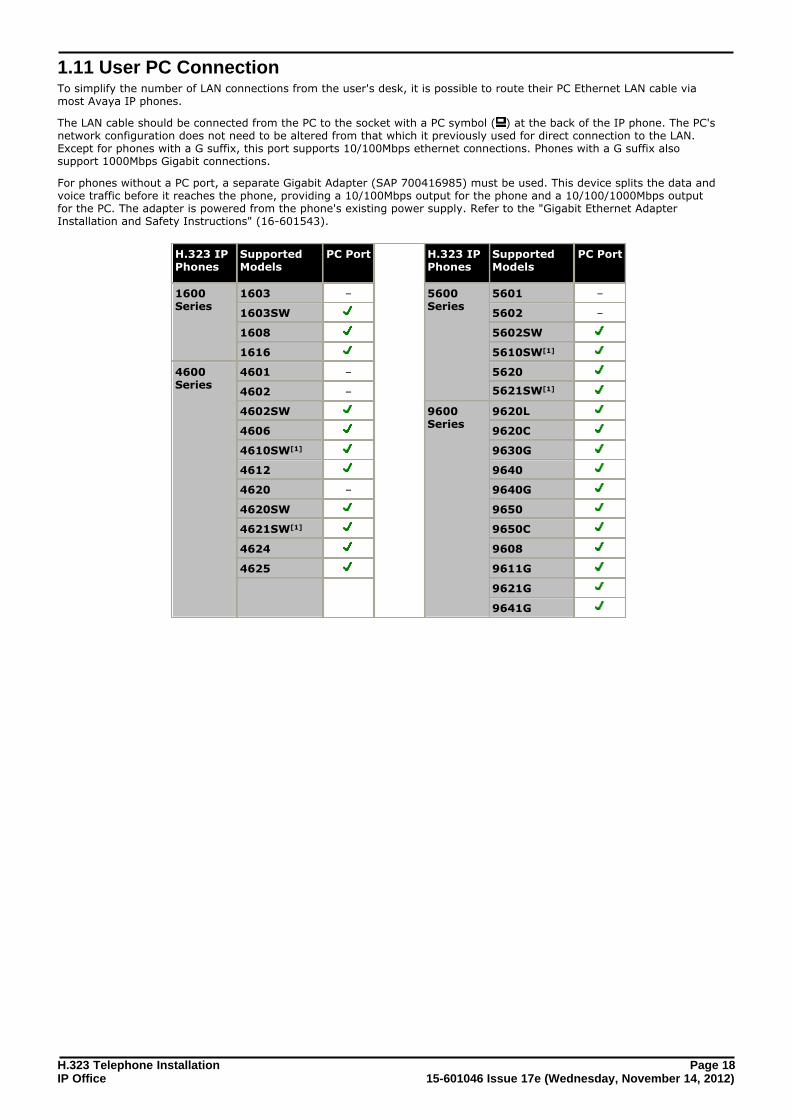
111 User PC ConnectionTo simplify the number of LAN connections from the users desk it is possible to route their PC Ethernet LAN cable viamost Avaya IP phones
The LAN cable should be connected from the PC to the socket with a PC symbol ( ) at the back of the IP phone The PCsnetwork configuration does not need to be altered from that which it previously used for direct connection to the LANExcept for phones with a G suffix this port supports 10100Mbps ethernet connections Phones with a G suffix alsosupport 1000Mbps Gigabit connections
For phones without a PC port a separate Gigabit Adapter (SAP 700416985) must be used This device splits the data andvoice traffic before it reaches the phone providing a 10100Mbps output for the phone and a 101001000Mbps outputfor the PC The adapter is powered from the phones existing power supply Refer to the Gigabit Ethernet AdapterInstallation and Safety Instructions (16-601543)
H323 IPPhones
SupportedModels
PC Port H323 IPPhones
SupportedModels
PC Port
1600Series
1603 ndash 5600Series
5601 ndash
1603SW 5602 ndash
1608 5602SW
1616 5610SW[1]
4600Series
4601 ndash 5620
4602 ndash 5621SW[1]
4602SW 9600Series
9620L
4606 9620C
4610SW[1] 9630G
4612 9640
4620 ndash 9640G
4620SW 9650
4621SW[1] 9650C
4624 9608
4625 9611G
9621G
9641G
H323 Telephone Installation Page 1915-601046 Issue 17e (Wednesday November 14 2012)IP Office
IP Office H323 IP Phones User PC Connection
112 Power Supply OptionsEach H323 IP phone requires a power supply They do not draw power from the phone system Listed below are thepower supply options that can be used
Power over Ethernet (PoE) OptionsIEEE 8023af is a standard commonly known as Power over Ethernet (PoE) It allows network devices to receive powervia the network cable using the same wires as the data signals All the Avaya H323 IP phones supported on IP Officealso support this standard
Where a large number of phones is being installed the use of PoE switches is recommended For other scenariosindividual PoE injector devices can be used to add PoE power support to the phones LAN connection from a non-PoEswitch
H323 IPPhones
SupportedModels
8023af PoEClass
H323 IPPhones
SupportedModels
8023af PoE Class
Class Idle Class Idle
1600Series
1603 2 44W 5600Series
5601 2 35W
1603SW 2 44W 5602 1 ndash
1608 2 37W 5602SW 2 41W
1616 2 27W 5610SW 2 31W
4600Series
4601 2 35W 5620 3 36W
4602 1 ndash 5621SW 2 ndash
4602SW 2 35W 9600Series
9620L 1 20W
4606 0 41W 9620C 2 39W
4610SW[1] 2 40W 9630G 2 46W
4612 0 41W 9640 2 39W
4620 3 40W 9640G 2 39W
4620SW 2 ndash 9650 2 47W
4621SW[1] 2 575W 9650C 2 37W
4624 0 41W 9608 1 208W
4625 3 645W 9611G 1 28W
9621G 2 349W
9641G 2 344W
These 1603 and 1603SW phones require a separate PoE Splitter unit in order to use PoE
middot Exceeding the Class limit of a PoE port or the total Class support of a PoE switch may cause incorrect operation
middot Note that for phones being used with an add-on button module unit an individual power supply must be usedrather than connection to a PoE switch
1600 Series PhonesThese phones can use either PoE as above or can be powered from using 1600 Series plug-top power supply units(PSUs) Different models of PSU exist for the various type of mains power outlets in different countries The PSU connectsto the phone using a barrel connector under the phone
46005600 Series Spare Wire Power OptionsThe following power supplies use the normally unused pin 7 amp 8 connections in the CAT3 or CAT5 network cable This isreferred to as spare wire or mid-span power supply units They can be used with 4600 Series and 5600 Series IPphones
H323 Telephone Installation Page 2015-601046 Issue 17e (Wednesday November 14 2012)IP Office
middot Avaya 1151D1 Power Supply Unit (PSU)A power supply unit for a single IP phone Has a LINE port for the LAN cable from the IP Office and a PHONE portfor the LAN cable to the IP phone Power into the PSU requires a 90 to 264V AC 47 to 63HZ mains supply Agreen LED indicates when power is available
middot Avaya 1151D2 Power Supply UnitSame as the 1151C1 above but with integral battery backup When AC mains supply is removed the battery willpower the IP phone for between 8 hours at light load (2 Watts) and 15 minutes at full load (20 Watts) A greenLED indicates when power is available A yellow LED indicates when the backup is charging The green LED flasheswhen the phone is running from the backup battery
9600 These phones only support the use of Power over Ethernet (PoE) If not being supplied by a PoE switch an Avaya SinglePort PoE injector (SPPOE-1A) can be used for each phone
H323 Telephone Installation Page 2115-601046 Issue 17e (Wednesday November 14 2012)IP Office
IP Office H323 IP Phones Power Supply Options
113 File Server OptionsDuring installation and maintenance the phones download various firmware files In order to do this a phonerequests files for an HTTPS server first If it gets no response it then tries to obtain the files from an HTTP server 4600and 5600 Series phones will then try TFTP The address of the server to use is provided as part of the DHCP responsethat the phone received from the DHCP server If the IP Office system is being used as the DHCP server the file serveraddress is set as part of the IP Office configuration For phones installed using static addressing the file server address isone of the addresses entered during installation
middot Each phone will attempt to request files from the file server every time it is restarted However if the phone doesnot receive any response it will continue restarting using the existing files that it has in its own memoryTherefore there is no requirement for the file server to be permanently available after initial installation
middot The IP Office system is currently not supported as a file server for 9608 9611 9621 and 9641 phonesThis also applies to using the IP Office Manager application acting as the file server These phones areonly supported when using a 3rd-party file server
middot The phones also use a server for the backup and restoration of user settings during phone operation Theaddress for this server is defined by a separate address set found in the 46xxsettingstxt file It is notnecessarily the same server that is used for the phone firmware However for IP Office operation the address ofthe IP Office server is recommended for use as the backuprestore file server
The following options are available for the file server for IP phones being installed on an IP Office system
File Server Description Up to XPhones
TFTP HTTP HTTPS
IP Office Manager When running IP Office Manager can act as aHTTPTFTP server for file requests from IPphones
5 ndash
IP Office UnitMemory Card
For IP Office control units fitted with anadditional memory card that card can beused to provided the software files For IP500V2 control units the System SD card is amandatory item and is pre-loaded with thephone firmware files during card creation andupgrades Various other files can beauto-generated by the IP Office if notpresent on the memory card
50
3rd PartySoftware
3rd Party HTTPTFTP file server software isavailable from many sources including Avaya
ndash
Control Unit Memory CardThe memory card used with IP500 and IP500 V2 systems can be used to store files including those used by Avaya IPPhones
middot Non-Avaya supplied Compact Flash memory cards can be used for this type of file storage However they will notsupport embedded voicemail
middot If an Avaya supplied memory card is used any files stored in this way will reduce the message storage capacity ofthe Compact Flash memory card
middot The IP500 V2 control unit requires a System SD card at all times During creation of this card a full set of IPOffice firmware files including those used by Avaya IP phones is placed onto the card
10
52
22
H323 Telephone Installation Page 2215-601046 Issue 17e (Wednesday November 14 2012)IP Office
114 File Auto-GenerationFor IP Office systems configured to use the systems own memory as the file server for the phones the system willauto-generate the necessary firmware files in response to a request from a phone if the actual file is not present inthe memory This feature is used for most of the file types except the bin firmware files
middot xxupgrade Files The first file that a phone requests when starting up is the xxupgrade file This file contains a list of the phone bin files that are available as part of the firmware set and the version numbers of those files If the version of afile differs from that which the phone already has loaded the phone will request the new file During this processthe phone may reboot after loading each file and then request the xxupgradetxt file again until it has updated allits firmware if necessary Separate files are provided for the different phone series
middot 16xxupgradetxt This file lists the firmware files that 1600 Series phones should load
middot 46xxupgradescr This file lists the firmware files that 4600 Series and 5600 Series phones should load
middot 96xxupgradetxt This file lists the firmware files that 9600 Series phones should load
middot 96x1Hupgradetxt This file list the firmware files that 9608 9611 9621 and 9641 phones should load
middot 46xxsettingstxt This file will match the file supplied with the IP Office Manager except
middot The BRURI value will be set to indicate the IP Office memory as the file server location for backup andrestore actions by the phones
middot The LANG1FILE to LANG4FILE values for 1600 Series and 9600 Series phones for non-English languagefiles is determined from the best match to the system locale and the most common user locales in the IPOffice system configuration Languages currently supported are Dutch French French (Canadian) GermanItalian Latin Spanish Portuguese Russian Spanish
middot Language files If the 46xxsettingstxt file is auto-generated the matching 1600 Series and 9600 Series phone language filesspecified in that file are also auto-generated
middot ltextgt_16xxdatatxt If the 46xxsettingstxt file is auto-generated it will specify the IP Office system as the location for phones tobackup and restore user settings If no file exists for a user a file will be auto-generated This feature is usedfor 1600 Series and 9600 Series phones
In all the cases above if a matching file is uploaded to the systems memory the auto-generation of that particular file isoverridden
115 Control Unit Memory CardThe memory card used with IP500 and IP500 V2 systems can be used to store files including those used by Avaya IPPhones
middot Non-Avaya supplied Compact Flash memory cards can be used for this type of file storage However they will notsupport embedded voicemail
middot If an Avaya supplied memory card is used any files stored in this way will reduce the message storage capacity ofthe Compact Flash memory card
middot The IP500 V2 control unit requires a System SD card at all times During creation of this card a full set of IPOffice firmware files including those used by Avaya IP phones is placed onto the card
21
10
52
52
H323 Telephone Installation Page 2315-601046 Issue 17e (Wednesday November 14 2012)IP Office
Installation
Chapter 2
H323 Telephone Installation Page 2415-601046 Issue 17e (Wednesday November 14 2012)IP Office
2 InstallationThe following is a summary of the major steps in the installation process The recommended installation method is to useDHCP where possible to use the IP Office system as the file server and to enable automatic user and extension creation
1IP Office Manager PC Check that IP Office Manager System Status Application and System Monitor are installed and can be used toconnect to the IP Office system Verify that you can receive the configuration from the system and send it back
2Voice Compression Channels The IP Office Unit must be fitted with voice compression channels Use either SSA or System Monitorapplication to verify that the voice compression channels are available SSA list the VCM channels on the Resources screen The initial lines of Monitor output include the item VCOMP= which will state the number ofchannels installed in the control unit
3Avaya IP Endpoint Licenses Each phone requires an Avaya IP Endpoint license Phones can register without a license but will not operateThe licenses are added to the IP Office configuration using IP Office Manager
4H323 Gatekeeper Settings The IP Office system has support for H323 phones enabled by default However the setting should be checked
5DHCP Server Setting DHCP is the recommended method for installation of IP phones on a IP Office system This requires a DHCP serverconfigured to support IP phones The IP Office system can be used for this If the customer want to use their ownDHCP server it will require additional configuration
6Phone File Server Setting If the IP Office system is being used for DHCP it also needs to be configured with the address of the file serverWhichever installation method and file server is selected the phone firmware files need to be added to the filesavailable on the server
7Extension and User Settings The IP Office system can be configured to automatically create user and extension entries in its configuration foreach IP phone that is installed It automatic creation is not used entries must be manually created for eachextension and user before the phones are installed
8Phone Connections Once the steps above have been completed the phones can be connected to the network If using DHCP thephones will automatically obtain IP address information and other settings and then start loading files If not usingDHCP the phones will have to be taken through a manual process of entering the IP address information andsettings
9Phone Registration Once the phones have downloaded all the files they require from the file server they will attempt to register withthe IP Office system The phones will prompt for entry of the extension number that they should use
10Testing Operation of the phones should be tested by making a number of calls including external calls
11Post InstallationIf Auto-creation was used for the extension and or user entries those settings should be disabled after installationof all the phones is completed This manual only details the minimum user configuration necessary for installationThe new users can now be fully configured to meet the customer requirements for those users
15
13
84
H323 Telephone Installation Page 2515-601046 Issue 17e (Wednesday November 14 2012)IP Office
Installation
21 LicensingRefer to the Licenses section for information on licensing rules
211 Checking the Serial NumberLicenses are issued against a unique feature keydongle serial number For IP500v2 control units that number is uniqueto the System SD card fitted to the system For IP500 control units that number is unique to the smart media cardinserted in the back of the control unit For any licenses entered into the system configuration to be valid they must belicenses issued against that serial number B5800 Branch Gateway licenses are issued against a unique PLDS Host ID
1Using IP Office Manager retrieve the configuration from the system
2Select System
3Select the System tab
4The feature key serial number is shown by the Dongle Serial Number field For B5800 Branch Gateway systemsthe PLDS Host ID is indicated by the PLDS HOST ID field
5This is the number that must be used to obtain licenses for the system It should also be used to check anylicenses received
13
H323 Telephone Installation Page 2615-601046 Issue 17e (Wednesday November 14 2012)IP Office
212 Adding LicensesUse the following procedure to add licenses to the telephone system configuration You can add multiple (cumulative)licenses
You must ensure that the licenses match the Dongle Serial Number shown in the system configuration This shouldbe shown in the file used to supply the licenses For B5800 Branch Gateway systems you must ensure that the licensesmatch the PLDS Host ID
It is recommended that you cut and paste the license keys from a supplied file rather than typing them in manually
1Using IP Office Manager receive the configuration from the telephone system
2Select License The current licenses in the system configuration are displayed For B5800 Branch Gateways select PLDSLicense
3To add a license click on and select License For B5800 Branch Gateway systems select PLDSLicense and select Send PLDS license file to Avaya BranchGateway
4Enter the license that you have been supplied into the field and click OK
5The type of the license should be displayed but with its License Status set to Unknown If the License Typewas not recognized check that it has been entered correctly
6Save the configuration back to the system and then receive the configuration from the system again
7The License Status should now be Valid
213 Reserving LicensesThis particular process cannot normally be done until the extension entry has been created If using automatic extensioncreation (the default) this means that license reservation cannot be done until after initial installation of the phoneHowever consideration should be given to using this setting with any existing phones already installed in order to ensurethat they retain their licenses if possible following the addition of other phones
Licenses are normally automatically assigned to extensions in order of registration However existing extensions canreserve a license in order to ensure they do not become unlicensed when new extensions added to the system manage toregister first following a system reboot
1Using IP Office Manager receive the configuration from the telephone system
2Select Extension and then select the H323 extension
3Select the VoIP tab
4The Reserve Avaya IP endpoint license setting is used to reserve an existing license for the extension
5Repeat the process for any other extensions for which you want to reserve the license
6Save the configuration back to the telephone system
25
H323 Telephone Installation Page 2715-601046 Issue 17e (Wednesday November 14 2012)IP Office
Installation Licensing
22 System H323 SupportThe IP Office system has H323 support enabled by default The following sections offer more information on configuringH323 support
middot Enabling the H323 Gatekeeper
middot Setting the RTP Port Range
middot Enabling RTCP Quality Monitoring
middot Adjusting DIffServ QoS
221 Enabling the H323 GatekeeperSupport for H323 telephones and lines is enabled by default However the settings should be checked
Enabling the H323 Gatekeeper1Using IP Office Manager retrieve the configuration from the system
2Select System
3Select the LAN1 or LAN2 tab depending on which of the systems LAN interfaces you want to use to supportH323 extensions
4Select the VoIP sub-tab
5Check that the H323 Gatekeeper Enable setting is selected
6If this setting needs to be changed save the configuration back to the system
27
28
29
31
H323 Telephone Installation Page 2815-601046 Issue 17e (Wednesday November 14 2012)IP Office
222 Setting the RTP Port RangeThe ports used for H323 VoIP calls vary for each call The range for the ports used can be adjusted in order to avoidconflict with other services If the customer has any internal firewalls or similar equipment that applies port filtering oronly forwards traffic based on the port used the range set here must be allowed by those devices
For each VoIP call receive ports are selected from the range defined below Even numbers in the range are used for thecalls incoming Real-Time Transport Protocol (RTP) traffic The same calls Real-Time Transport Control Protocol (RTCP)traffic uses the RTP port number plus 1 that is the odd numbers
It is recommended that only port numbers greater than or equal to 49152 but strictly less than 65535 are used thatbeing the range defined by the Internet Assigned Numbers Authority (IANA) for dynamic usage
Checking the Port Range1Using IP Office Manager retrieve the configuration from the system
2Select System
3Select the LAN1 or LAN2 tab depending on which of the systems LAN interfaces you want to use to supportH323 extensions
4Select the VoIP sub-tab
5Check the RTP Port Number Range shown Remember that the matching RTCP traffic uses the same range plus1
middot Port Range (Minimum) Default = 49152 Range = 1024 to 65280 This sets the lower limit for the RTP port numbers used by the system Choosing a minimum range of lessthan 1024 should only be done after careful analysis of the overall configuration
middot Port Range (Maximum) Default = 53246 Range = 1278 to 65534 This sets the upper limit for the RTP port numbers used by the system The gap between the minimum andthe maximum must be at least 254 Choosing a minimum range of less than 1024 should only be done aftercareful analysis of the overall configuration
6If these settings need to be changed do so and then save the configuration back to the system
H323 Telephone Installation Page 2915-601046 Issue 17e (Wednesday November 14 2012)IP Office
Installation System H323 Support
223 Enabling RTCP Quality MonitoringAvaya IP phones support call quality monitoring This is done using port 5005 both on the system and the phonesEnabling the option below instructs the phones to provide call quality information to the IP Office system on that port
Enabling RTCP monitoring provides the system with measures of packet delay packet loss and jitter That informationcan be accessed using the System Status Application and IP Office System Monitor applications The system can also beconfigured to output alarms when the call quality values exceed set levels
Enabling the RTCP Quality Monitoring1Using IP Office Manager retrieve the configuration from the system
2Select System
3Select the LAN1 or LAN2 tab depending on which of the systems LAN interfaces you want to use to supportH323 extensions
4Select the VoIP sub-tab
5Check that the H323 Gatekeeper Enable setting is selected
6If this setting needs to be changed save the configuration back to the system
H323 Telephone Installation Page 3015-601046 Issue 17e (Wednesday November 14 2012)IP Office
Setting the Quality of Service Alarm LevelsThe system can send alarms to the System Status Application It can also send the same alarms to SNMP emails orSyslog destinations For details of how to configure these refer to the IP Office Manager documentation The settingsbelow are used to set the levels which if exceeded will cause an alarm to be sent at the end of a call
1Using IP Office Manager retrieve the configuration from the system
2Select System
3Select the System Events tab and then the Configuration sub-tab
4The QoS Parameters are used by the system to trigger alarms The default settings match the limits usuallyacceptable for good call quality
5If the settings are adjusted save the configuration back to the IP Office system
H323 Telephone Installation Page 3115-601046 Issue 17e (Wednesday November 14 2012)IP Office
Installation System H323 Support
224 Adjusting DiffServ QoSDiffServ is used to apply different quality of service tags to the voice (RTP) and control signal (RTCP) elements of a VoIPcall The IP Office system itself does not apply any different priority to data packets its receives or sends based on theirtags However when being used in a network where QoS is being used for prioritization by other devices the IP Officessettings should be set to match those expected for voice calls and their associated control signalling
Enabling the DiffServ QoS Settings1Using IP Office Manager retrieve the configuration from the system
2Select System
3Select the LAN1 or LAN2 tab depending on which of the systems LAN interfaces you want to use to supportH323 extensions
4Select the VoIP sub-tab
5Check the DiffServ Settings that are being used by the system Note that the 2 rows are linked the upper rowshows the DiffServ values in Hex numbers the lower row shows the values in decimal The hex values are equal tothe decimal multiplied by 4 Either row can be used to set the required values
6If these settings need to be changed do so and then save the configuration back to the system
H323 Telephone Installation Page 3215-601046 Issue 17e (Wednesday November 14 2012)IP Office
225 System Default CodecsBy default all VoIP devices added to the IP Office configuration use the systems default codec preferences This is shownby the Codec Selection setting on an IP trunk or extension being set to System Default
In addition to changing the default codec preference order for all VoIP trunks and extension the codec preferences usedby a particular trunk or extension can be adjusted However the use of the common system settings ensures codecconsistency between trunks and extensions
Changing the Default Codec Preferences1Using IP Office Manager retrieve the configuration from the system
2Select System
3Select the Codecs sub-tab
4The Available Codecs list shows which codecs the system supports The codecs in this list which enabled arethose that can be used in other configuration forms including the adjacent default selection
middot WARNING Deselecting a codec in this list will automatically remove it from any line system or extension
codec lists where it was being used
5The Default Selection section is used to set the default codec preference order This is used by all IP (H323 andSIP) extensions and lines on the system that have their Codec Selection setting set to System Default This isthe default for all new added IP extension and lines
6If these settings need to be changed do so and then save the configuration back to the system
H323 Telephone Installation Page 3315-601046 Issue 17e (Wednesday November 14 2012)IP Office
Installation System H323 Support
23 DHCP SettingsThe recommendation for H323 phone installation is to use DHCP especially if a large number of phones are beinginstalled Using DHCP simplifies both the installation and maintenance
There are a number of options around which server is used for the DHCP support for the H323 phones
middot If the IP Office system is to be used as a DHCP server for the network use the processes below to check andconfigure the systems DHCP settings
middot If a separate DHCP server is used by the customers network that DHCP server may need to be configured tosupport DHCP requests from IP phones see Alternate DHCP Server Setup
middot The IP Office can be configured to only provide DHCP support for Avaya phones That option can be used to allowit to be used in conjunction with a separate customer DHCP server This removes the need to configure thecustomers DHCP server for IP phone support
middot WARNING
Enabling an additional DHCP server in a network can cause connection issues for all devices on the networkEnsure that you the user and the users network administrator all agree upon the correct choice of DHCP serveroption
84
H323 Telephone Installation Page 3415-601046 Issue 17e (Wednesday November 14 2012)IP Office
Enabling IP Office DHCP Support
The following are the main steps for enabling the IP Office system to support DHCP operation for IP phones
1Enable DHCP and Set the Number of Addresses
2Check the Site Specific Option Numbers The IP Office defaults match the defaults used by Avaya IP phones However it is important to check these valuesand to be aware of their potential usage
3Set the File Server Settings If the IP Office system is set to provide DHCP for IP phones that role includes telling the phones the location ofthe file server they should use for phone firmware even if that file server is not the IP Office system
35
36
37
H323 Telephone Installation Page 3515-601046 Issue 17e (Wednesday November 14 2012)IP Office
Installation DHCP Settings
231 System DHCP Support1Using IP Office Manager retrieve the configuration from the system
2Select System
3Select the LAN1 or LAN2 tab depending on which of the systems LAN interfaces you want to use to supportH323 extensions
4Select the LAN Settings tab
5If the DHCP Mode is set to Server the Number of DHCP IP Addresses value set how many IP addresses thesystem can issue Those addresses are use the IP Address of the system as the starting point
6Click the Advanced button or select the DHCP Pools tab if already visible
7The settings on this tab allow adjustment of the DHCP setting including adding multiple ranges of DHCP numbersthat the IP Office system can support Note that address ranges outside those of the IP Office systems own subnetmay also require the creation of appropriate IP routes to ensure traffic routing between the subnets
8If the Apply to Avaya IP Phone Only option is selected the IP Office will act as a DHCP server for Avaya phonesonly This option cannot be used if also supporting 1100 Series and 1200 Series phones
9If the settings have been changed save the configuration back to the system
H323 Telephone Installation Page 3615-601046 Issue 17e (Wednesday November 14 2012)IP Office
232 System Site Specific Option NumbersWhen requesting address settings from a DHCP server each phone also requests additional information that the DHCPserver may have It does this by sending a Site Specific Option Number (SSON) If the DHCP server has informationmatching the SSON that information is included in the DHCP response
4600 and 5600 Series phones use 176 as their default SSON 1600 and 9600 Series phones use 242 as their defaultSSON However through the phones own menus the SSON it uses can be altered For those phones using the IPOffice system for DHCP the SSON numbers that the IP Office supports are set in the IP Office systems configurationThe values used by the phones and supported by the IP Office system must match
Changing the Systems SSON Settings1Using IP Office Manager retrieve the configuration from the system
2Select System
3Select the LAN1 or LAN2 tab depending on which of the systems LAN interfaces you want to use to supportH323 extensions
4Select the VoIP sub-tab
5Check that the Site Specific Option Number settings match those required for the phone being supported Thedefault for 4600 and 5600 Series phones is 176 The default for 1600 and 9600 Series phones is 242
6If this setting needs to be changed save the configuration back to the system
71
H323 Telephone Installation Page 3715-601046 Issue 17e (Wednesday November 14 2012)IP Office
Installation DHCP Settings
24 File Server SettingsAs part of the installation process the phone will request files from a file server If being installed using DHCP theyobtain the address of the file server as part of the DHCP response from the DHCP server If being statically installed thefile server address is entered into the phone as part of the static addressing process
The file server options are
middot The IP Office systems own memory card can be used as the source for the files used by the 11001200 Seriesphones This is the recommended option and can be used for up to 50 phones
middot The IP Office Manager application can also act as a file server for up to five (5) phones
middot If either of the options above are not acceptable a 3rd party HTTP file server is required The necessary phonefirmware files then need to be loaded onto that server
H323 Telephone Installation Page 3815-601046 Issue 17e (Wednesday November 14 2012)IP Office
241 System File Server SettingsIf the IP Office system is being used for DHCP support for the IP phones various settings in the IP Office systemsconfiguration are used to set the file server addresses sent to the phones in the DHCP responses
1Using IP Office Manager retrieve the configuration from the system
2Select System
3Select the System tab
4 Check the Phone File Server Type setting
middot Memory Card Use the systems own memory card by providing its own IP address as the TFTP and HTTP file server values inthe DHCP response This is the default settingManager Use the IP Office Manager application as the TFTP and HTTP file server This option is only supported for amaximum of 5 IP phones This option uses the separate Manager PC IP Address set in the configurationThe default of 0000 is used by the system to broadcast for any available IP Office Manager application onthe network
middot Custom This option uses the separate TFTP Server IP Address and HTTP Server IP Address values set in theconfiguration as the files server addresses in the DHCP response given to phones
middot The TFTP Server IP Address default of 0000 is a broadcast on the network for a TFTP server
middot The HTTP Server IP Address default of 0000 is no HTTP request
5The Avaya HTTP Clients Only option can be used to restrict the system to responding to file requests fromAvaya phones and applications only This option should not be used if the system is also supporting 1100 and or1200 Series phones
6If any changes have been made save the configuration back to the system
33
H323 Telephone Installation Page 3915-601046 Issue 17e (Wednesday November 14 2012)IP Office
Installation File Server Settings
242 CreatingEditing the Settings FileDuring installation the phones request files first downloading an xxupgrade file from the file server They then followthe instructions within that file to request further files if necessary Various different xxupgrade files exist for the differentphone series These are provided as part of the phone firmware The xxupgrade files should not be edited or changedin any way
The last line of all the xxupgrade files instructs the phones to request the 46xxsettingstxt file This file can be used toset site specific settings for all the Avaya H323 IP phones being supported on a particular site
When using the IP Office system as the file server the IP Office system will auto-create a suitable 46xxsettingstxtfile based on various IP Office system configuration settings It will only do this if there is no actual 46xxsettingstxt fileavailable on the server
Manually Editing the File1Locate the 46xxsettingstxt file on the file server
2Using Windows Notepad or any other plain text editing tool open the 46xxsettingstxt file
3Edit the file as required The file contains numerous comments and notes Further details of the various settingsare contained in the appropriate LAN Administrator Manual This manual only contains a limited number ofexamples of the settings available Note also that the files contain a wide range of settings used on other Avayatelephone systems that may not work with IP Office systems
middot 9600 Series IP Telephones Administrator Guide (16-300698)
middot 96x1 Series IP Telephones Administrator Guide (16-300699)
middot 1600 Series IP Telephones Administrators Guide (16-601443)
middot 4600 Series IP Telephone LAN Administrator Guide (555-233-507)
4A character at the start of a line comments out the command on that line Note however that for some optionsthe phones will assume a default value if the option in the 46xxsettingstxt file is commented out For exampleif SET PHNOL is commented out the phones will assume the addition of a dial 9 prefix to numbers
Dialing PrefixFor IP Office systems the addition or removal of dialing prefixes is normally done by the IP Office system rather thanindividual phones or applications For IP Office operation the following changes are recommended in the ENHANCED LOCAL
DIALING RULES section of the 46xxsettingstxt file
middot Change SET ENHDIALSTAT 0 to ENDIALSTAT 0
middot Change SET PHNOL 9 to SET PHNOL
8021Q TaggingUnless specifically required for the customer network for IP Office operation it is recommended that SET L2Q 0 is
changed to SET L2Q 2
WML Web Server SetupIf a WML web site has been setup for viewing by phone users see WML Server Setup the site address is set throughthe 46xxsettingstxt file Change WMLHOME http to WMLHOME followed by the required address
10
22
92
H323 Telephone Installation Page 4015-601046 Issue 17e (Wednesday November 14 2012)IP Office
16009600 Series Phone LanguagesIn addition to English the 1600 and 9600 phones can support up to four (4) other languages This is done by thephones which download the language files specified in the 46xxsettingstxt file Currently nine (9) non-Englishlanguage files are provided as part of the IP Office Manager installation
Language 1600 File 9600 File
Dutch mlf_dutchtxt mlf_9600_dutchtxt
French Canadian mlf_french_cantxt mlf_9600_french_cantxt
French mlf_french_paristxt mlf_9600_french_paristxt
German mlf_germantxt mlf_9600_germantxt
Italian mlf_italiantxt mlf_9600_italiantxt
Portuguese mlf_portuguesetxt mlf_9600_portuguesetxt
Russian mlf_russiantxt mlf_9600_russiantxt
Spanish mlf_spanishtxt mlf_9600_spanishtxt
Spanish (Latin American) mlf_spanish_latintxt mlf_9600_spanish_latintxt
The files to download to the phones are defined in the SETTINGS1603 SETTINGS1608 and SETTINGS1616 sections
of the 46xxsettingstxt file To have the phone download a language file remove the in front of one of the SET
options and change the file name to match the required language If using the IP Office system as the file server theappropriate language files based on the IP Office system configuration can be provided using file auto-generation
BackupRestorePhones can use an HTTP server as a location to which the users phone settings are backed up and restore when they logon or off the phone See BackupRestore Settings for full details
22
52
H323 Telephone Installation Page 4115-601046 Issue 17e (Wednesday November 14 2012)IP Office
Installation File Server Settings
243 Loading Software Files onto the SystemThe phone firmware suitable for IP Office system operation is supplied as part of the IP Office Manager software and iscopied onto the PC when IP Office Manager is installed No other firmware should be used with IP Office unlessspecifically documented
There are a number of methods by which the firmware installed with IP Office Manager can be copied onto the telephonesystems memory card The method used depends mainly on the type of control unit
middot WARNING
A memory card should never be removed from a running system without either the card or the system first beingshutdown IP Office Manager should be used to shutdown the memory card before it is removed from the system
middot For IP Office operation only the phone bin files need to be present on the memory card Other files required bythe phones are automatically generated by the system in response to requests from the phones
IP500 V2 Control UnitThe systems System SD card is used to store the files This is a mandatory card that is present in all IP500 V2 systemsThe firmware files are loaded onto the card in a number of ways
middot If the system was upgraded using the Recreate SD Card option in IP Office Manager the firmware isautomatically copied onto the card as part of that process
middot If the system was upgraded using IP Office Managers Upgrade Wizard if the Upload System Files option wasselected the firmware is copied onto the card as part of that process The Upload System Files option is enabledby default
IP500 Control Unit
The compact flash memory card is used to store the files This is an option card that may only be present if the system isusing embedded voicemail The files need to be copied manually onto the memory card This can be done in a number ofways
middot Files can be copied remotely onto the card in a running system using IP Office Managers embedded filemanagement
middot The card can be shutdown and removed from the system Files can then be copied onto the card using a PC with asuitable memory card slot
If you think the correct files are not present you can use the embedded file manager part of IP Office Manager to checkthe files on the card and to copy the files onto the card if necessary
Using Embedded File Manager to CheckUpload Files
Embedded file manager allows you to remote see the files on the memory card used by the telephone system It alsoallows you to upload new files
1In IP Office Manager select File | Advanced | Embedded File Management
2The Select IP Office menu is displayed
3Select the telephone system and click OK
4Enter the name and password for the system These are the same as used for configuring the system
H323 Telephone Installation Page 4215-601046 Issue 17e (Wednesday November 14 2012)IP Office
5The contents of the memory card are displayed
6For an IP500 memory card all the firmware files are held in the top level folder For an IP500 V2 system use thefolder tree to navigate to System SD | SYSTEM | PRIMARY
7Individual files can be copied onto the card by using drag and drop or by selecting File | Upload File (IP500) orFile | Upload System Files (IP500 V2)The whole set of phone firmware files that IP Office Manager hasavailable can be copied by selecting File | Upload Phone Files
middot The source files can be found on the IP Office Manager PC in CProgram FilesAvayaIPOfficeManagermemory CardsCommonsystemprimary
H323 Telephone Installation Page 4315-601046 Issue 17e (Wednesday November 14 2012)IP Office
Installation File Server Settings
Manually Copying FilesFiles can be copied onto the memory card by placing it into a PC with a suitable memory card slot
middot WARNING
A memory card should never be removed from a running system without first being shutdownIP Office Managershould be used to shutdown the memory card before it is removed from the system
1Using IP Office Manager select File | Advanced | Memory Card Command | Shutdown
2The Select IP Office menu is displayed
3Select the telephone system and click OK
4Enter the name and password for the system These are the same as used for configuring the system
5You may be prompted for which card you want to shutdown Select System and click OK
6On the back of the control unit check that the LED for the memory card slot is off before removing the memorycard
7Place the card into the PCs memory card slot and examine the contents
8For an IP500 memory card all the firmware files are held in the top level folder For an IP500 V2 system use thefolder tree to navigate to System SD | SYSTEM | PRIMARY The source files can be found on the IP OfficeManager PC in CProgram FilesAvayaIP OfficeManagermemory CardsCommonsystemprimary
9When the card is reinserted into the system card usage is automatically restarted
H323 Telephone Installation Page 4415-601046 Issue 17e (Wednesday November 14 2012)IP Office
244 Loading Files onto a 3rd Party ServerThe phone firmware files are installed as part of the IP Office Manager application and are found in the applicationsinstallation directory By default the directory is found at cProgram FilesAvayaIP OfficeManager
The same firmware files can also be obtained directly from the software package used to install IP Office Manager withouthaving to perform the installation The files are located in the program filesAvayaIP OfficeManager sub-folder ofthe installation directory
Note that these sets of files include bin files that are also used for other devices including the IP Office system itself
H323 Telephone Installation Page 4515-601046 Issue 17e (Wednesday November 14 2012)IP Office
Installation File Server Settings
25 User and Extension CreationWhen a new H323 telephone registers with the system the IP Office can automatically create a new extension entry forthe telephone in its configuration It can also automatically create a new user entry for the telephone Alternatively if thephone registers using an extension number for which entries already exist those entries are used so long as no otherphone is already using them
For new installations the use of Auto-creation is recommended for ease of installation The auto-create options can bedisabled after installation If Auto-creation is not used extension and user entries need to be manually added to theconfiguration before attempting to install the phones
Note Auto-creation is not supported on B5800 Branch Gateway systems
251 Auto-CreationWe recommend that you use Auto-creation to create extensions and user entries The settings can be disabled afterinstallation
Note Auto-creation is not supported on B5800 Branch Gateway systems
Switching Auto-Create OnOff
1Using IP Office Manager receive the configuration from the system Select System
2Select the LAN1 or LAN2 tab depending on which of the systems LAN interfaces you want to use to supportH323 extensions
3Select the VoIP sub-tab
4The H323 Auto-create Extn and H323 Auto-create User settings are used for H323 phone installation Setthese as required for the installation If either option is not enabled it will be necessary to manually create theextension entries and or manually create the user entries before installing the phones
5If the settings have been changed save the configuration back to the system
46 46
H323 Telephone Installation Page 4615-601046 Issue 17e (Wednesday November 14 2012)IP Office
252 Manually Creating UserIf the Auto-create User option is not enabled you must manually create a user entry for each phone being installedUse the procedure below to manually create an entry It will also prompt whether a matching extension entry should alsobe created
Manually Creating User Entries1Using IP Office Manager receive the systems configuration
2To display the list of existing users click User in the left-hand panel Right-click on the right-hand panel andselect New
a In the User tab set the following
middot Name Enter a name for the extension user The name must be unique If voicemail is in use this name will beused as the basis for a new mailbox with matching name
middot Extension This must match the extension number
bClick on the Button Programming tab For the first three buttons you must click on the Action field andselect Appearance | Appearance
c Click on OK
d IP Office Manager will prompt whether it should also create a matching extension If the Auto-create Extnoption is not enabled select H323 Extension and click OK Otherwise select None and click OK
3Save the configuration changes back to the system
253 Manually Creating ExtensionsIf the Auto-create Extn option is not enabled you must manually create an extension entry for each phone beinginstalled This can be done either as part of the process of manually creating users or it must be done separatelyusing the process below
Manually Creating Extension Entries1Using IP Office Manager retrieve the systems configuration
2To display the list of existing extensions click Extension in the left-hand panel Right-click on the right-handpanel and select New
a In the Extn tab set the following
middot Extension ID For a VoIP extension enter any number so long as it is unique ie not already used by anotherextension
middot Base Extension Enter the extension number to assign to the phone Again this must be unique This value is used toassociate the extension with the user who has the same extension number
bTo add the new extension click OK
3Save the configuration changes back to the system
Codec SelectionIf the Codec Selection is left set to System Default the extension will use the system codec preferences In mostcases this is preferred and any changes required should be made at the system level to ensure consistency for all IPtrunks and extensions
However if required the Codec Selection of each individual trunk and extension can be adjusted to differ from thesystem defaults
1Using IP Office Manager retrieve the systems configuration
2To display the extensions settings click Extension in the left-hand panel
3Select the VoIP tab
4Change the Codec Selection to Custom
45
45
46
32
H323 Telephone Installation Page 4715-601046 Issue 17e (Wednesday November 14 2012)IP Office
Installation User and Extension Creation
5The Unused and Selected lists can be used to select which codecs the device uses and their order of preference
6Save the configuration changes back to the system
H323 Telephone Installation Page 4815-601046 Issue 17e (Wednesday November 14 2012)IP Office
26 Phone ConnectionIn this process the phone is connected to its power source and to the ethernet LAN As soon as the phone is powered upit will start to request information
1Do not start this process until all the preceding steps in the Installation Summary have been completed
2Connect the network LAN cable to the data-in socket of the power supply being used for the phone
3Connect the LAN cable supplied with the IP phone from the power supplies data and power out socket to thesocket with a LAN port symbol ( ) at the back of the IP phone
4The phones message indicator should glow red for a few seconds The phone will then begin its software loadingprocess After a short delay the phone displays Initializing and then Loadinghellip The loading phase may take afew minutes
middot If the phone has an existing software boot file (ie it has been previously installed) it will load that file andthen display Starting
middot If the phone displays No Ethernet check the connection to the LAN
5The phone displays DHCP and a timer as it attempts to request an IP address and other information from a DHCPserver
middot To switch to static address installationPress whilst DHCP is shown See Static Address Installation
6After a few seconds DHCP negotiation should be completed If the timer reaches more than 60 seconds it couldindicate an error in either the network or DHCP server configuration
7Once DHCP has completed successfully the phone will request files from the file server indicated in the DHCPresponse The first file requested details the other files that the phone should also load The phone will first makeits file request using HTTPS If this fails it will make the same request using HTTP If that fails it will make a finalrequest using TFTP If all requests for a file fail the phone will fallback to using the current version of the file it hasin its own memory
8The phone will go through a cycle of requesting files loading files and then transferring the files into its flashmemory
9Following file loading the phone displays Ext = See Phone Registration
24
49
51
H323 Telephone Installation Page 4915-601046 Issue 17e (Wednesday November 14 2012)IP Office
Installation Phone Connection
27 Static Address InstallationStatic addressing is only necessary when a DHCP server is unavailable or not desired For ease of maintenance andinstallation it is strongly recommended that a DHCP server used and that static addressing is avoided Following anyboot file upgrade of the phones firmware static address information may require reinstallation
The use of static address installation is not supported with 4601 and 5601 phones
1600 4600 and 5600 Series Phones1Follow the steps in Phone Connection until DHCP is shown on the phone display Press at this point to switch
the phone to static address installation Existing 4600 and 5600 Series phones can be made to start static addressinstallation while idle by pressing MUTE 2 3 3 7 (MUTE A D D R )
2The phone will display a sequence of settings and the existing value for each of those settings To accept thecurrent value press or enter a value and then press
3While entering data in the following actions it may sometimes be necessary to backspace The method for doingthis varies according to the phone type
middot 4602 5602 Speaker key
middot 4606 Conference key
middot 4612 amp 4624 Previous key
middot 4610 4620 4625 5610 5620 Left-most key
4The settings shown for static address installation are
middot Phone = This is the phones IP address To accept the current value press or enter a value and then press Ifentering a new value press the key to enter a character between digits
middot CallSv = This is the address of the H323 gatekeeper For IP Office systems this is the IP address of the IP Office LAN
middot CallSvPort = This is the Gatekeeper transport layer port number For Avaya IP phones the value used should be 1719 Toaccept the current value press or enter a value and then press
middot Router = This is the address of the phones default IP gateway For IP Office this is typically the IP address of the IPOffice LAN To accept the current value press or enter a value and then press
middot Mask = This is the phones IP Mask (also called the subnet mask) The mask is used with the IP address to indicatethe phones subnet This should match the IP mask set for the IP Office Unit
middot FileSv = This is the address of the file server from which the phone should request software and settings files Enterthe address of the TFTP or HTTP configured with the Avaya IP phone software file set
middot 8021Q = To change the setting press Press to accept the value
middot VLAN ID = For details of VLAN configuration see VLAN and IP Phones
5If you go through without changing anything the phone displays No new values Press If the phone displaysEnter command power off and on again
6Once all the values have been entered or the existing values accepted the phone will display Save new valuesTo save the values press The phone will save the values and then restart using those values
7The phone registration menu is displayed
48
59
51
H323 Telephone Installation Page 5015-601046 Issue 17e (Wednesday November 14 2012)IP Office
9600 Series Phones1When the option to program is displayed press the key
2When Enter code is displayed enter the administrative procedures passcode and press The default passcodeis CRAFT (2 7 2 3 8)
3Scroll the menu to ADDR and select this option to start the address procedure
4The list of required addresses is shown If the phone had any existing values they are shown Otherwise if thephone is new or has been cleared all the addresses are set to 0000
5Set each address in turn by highlighting it and selecting Change Enter the new address value and then selectSave To enter a in IP addresses press The values that need to be set are
middot Phone = This is the phones IP address To accept the current value press or enter a value and then press Ifentering a new value press the key to enter a character between digits
middot Call Server = This is the address of the H323 gatekeeper For IP Office systems this is the IP address of the IP Office LAN
middot Router = This is the address of the phones default IP gateway For IP Office this is typically the IP address of the IPOffice LAN To accept the current value press or enter a value and then press
middot Mask = This is the phones IP Mask (also called the subnet mask) The mask is used with the IP address to indicatethe phones subnet This should match the IP mask set for the IP Office Unit
middot HTTP File Server = This is the address of the HTTP file server from which the phone should request software and settings files
middot HTTPS File Server = This is the address of the HTTPS file server from which the phone should request software and settings filesThe phone will attempt to use this address if set before using HTTP
middot 8021Q = To change the setting press Press to accept the value
middot VLAN ID = For details of VLAN configuration see VLAN and IP Phones
middot VLAN Test = When using VLAN this is the time in seconds the phone will wait from a response from the DHCP server in theVLAN before falling back to normal non-VLAN operation
6When all the values are set as required press Back
7Press Exit The phone will restart using the new values
8The phone registration menu is displayed
71
59
51
H323 Telephone Installation Page 5115-601046 Issue 17e (Wednesday November 14 2012)IP Office
Installation Static Address Installation
28 Phone RegistrationFor new phones and phones that have been reset the phone will request an extension number If auto-create isenabled the extension number used if free will create new extension and user entries in the IP Office configuration Ifauto-create is not enabled the extension number used must match a VoIP extension entry within the IP Officeconfiguration see Manually Creating Extensions
1Following file loading the phone will request extension information
middot Ext = Enter the extension number the phone should use and press Wrong Set Type is displayed if you try touse the extension number of an existing non-IP extension
middot Password = The password used is as follows
middot If using auto-create for a new user and extension just enter any number and press Any digits enteredare not validated or stored
middot If not using auto-create enter the users Login Code as set in the IP Office configuration
2Test that you can make and receive calls at the extension
71 45
45
H323 Telephone Installation Page 5215-601046 Issue 17e (Wednesday November 14 2012)IP Office
29 BackupRestore Settings1600 and 9600 Series H323 IP Telephones support using an HTTP server as the location to which they can backup andrestore user-specific data The address for this backup server is set separately from that of the file server used for phonefirmware
These options are used if the location of the HTTP server for backuprestore has been specified in the phone 46xxsettingstxt file
middot The address of the HTTP server for backuprestore operation is separate from the address of the HTTP server usedfor phone firmware files downloads
middot The HTTP server being used for backuprestore will require configuration changes to allow the phones to send filesto it
middot If the IP Office system is being used as the file server for phone installation it can also be used for the phonebackup and restore functions That includes file auto-generation When using auto-generation some settingswithin the restore file are based on the users IP Office settings This is therefore the recommended solution wherepossible
Backup is used when the phone user logs out of the phone During the log out process the phone creates a filecontaining the user specific data and sends that to the BRURI location The file is named with the users extensionnumber as a prefix to _16xxdatatxt for example 299_16xxdatatxt
Restore is used when a user logs in at the phone The phone sends a file request for the appropriate file based on theusers extension number If the file is successfully retrieved the phone will import the settings and after a Retrieval OKmessage continue as normal If the file cannot be retrieved a Retrieval failed message is displayed and the phone willcontinue with its existing settings
Specifying the BRURI ValueIf you are using the IP Office system as the file server it is recommended that you also use it as the backup and restoreserver This option requires no additional configuration If there is no 46xxsettingstxt file on the IP Office system itwill auto-generate the file when it is requested by a phone and will include its own IP address as the backuprestoreserver address If there is 46xxsettingstxt file on the IP Office system you can edit the backuprestore server addressmanually using the process below to set it to match the systems IP address
If you want to use another server edit the BRURI value in the 46xxsettingstxt file You will also need to ensure thatthe server being used is configured to allow the uploading of files to the specified folder on the server
1Open the 46xxsettingstxt file
2Locate the line containing the SET BRURI value
3If the line is prefixed with characters remove those and any spaces
4After SET BRURI enter a space and then the address of the HTTP backup server for example SET BRURIhttp192168028 If necessary specify the path to a specific server directory andor include a specific portnumber for example SET BRURI http192168028backups8080
HTTP AuthenticationHTTP Authentication can be supported If set it will be used for both the backup and the restore operations Theauthentication credentials and realm are stored in the phones programmable non-volatile memory which is notoverwritten when new firmware is downloaded
Both the authentication credentials and realm have a default value of null If the HTTP server requires authentication theuser is prompted to enter new credentials using the phone If the authentication is successful the values used are storedand used for subsequent backup and restore operations
Manual BackupRestore ControlUsers can request a backup or restore using the Advanced Options BackupRestore feature as detailed in the user guidefor the specific telephone model
22
H323 Telephone Installation Page 5315-601046 Issue 17e (Wednesday November 14 2012)IP Office
Installation BackupRestore Settings
291 Example FileThe following is an example of a backuprestore file for a 1600 Series phone user Note that values are not written unlessthe setting has been changed from its default
If the backup and restore is being done using file auto-generation those items indicated by are controlled byvalues stored and supplied by the users IP Office settings
File Fields Description
ABKNAME001=Extn201ABKNUMBER001=201ABKNAME002=Extn201adABKNUMBER002=201ABKNAME003=Extn203ABKNUMBER003=203Redial=0Call Timer=0Visual Alerting=1Call Log Active=1Log Bridged Calls=1Log Line Calls=1Log Calls Answered by Others=0Audio Path=2Personalized Ring=7Handset AGC=1Headset AGC=1Speaker AGC=1Error Tone=1Button Clicks=0Display Language=English
ABKNAMEmmmABKNUMBERmmm
These paired entries are used for personalcontacts entered into the phone The mmmvalue in each pair in replace by a 3-digitnumber starting with 001 The first line of thepair stores the contact name the second linestores the phone number for the contact
LANGUSER Display language The language name isstored
LOGACTIVE Call log active on (1) or off (0)
LOGBRIDGED Log bridged calls on (1) or off (0)
LOGLINEAPPS Log line calls on (1) or off (0)
LOGOTHERANS Log calls answered by others on (1) or off(0)
OPTAGCHAND Handset Automatic Gain Control on (1) or off(0)
OPTAGCHEAD Headset Automatic Gain Control on (1) or off(0)
OPTAGCSPKR Speaker Automatic Gain Control on (1) or off(0)
OPTAUDIOPATH Audio Path
OPTCLICKS Button Clicks on (1) or off (0)
OPTERRORTONE Error Tone on (1) or off (0)
PERSONALRING Personalized Ring A numeric value (1 to 8)for the selected ring is stored
PHNREDIAL Redial
PHNSCRONCALL Go to call screen on calling on (1) or off (0)
PHNSCRONALERT Go to call screen on ringing on (1) or off (0)
PHNTIMERS Call Timer on (1) or off (0)
PHNVISUALALERT Visual alerting on (1) or off (0)
22
H323 Telephone Installation Page 5415-601046 Issue 17e (Wednesday November 14 2012)IP Office
292 IIS Server ConfigurationCreate a backup folder under the root directory of your web server All backup files will be stored in that directory Forexample if your backup folder is CInetpubwwwrootbackup the 46xxsettingstxt file should have a line similarto SET BRURI httpwwwwebsitecombackup
1Go to Start | Settings | Control Panel | Administrative Tools and select depending on the Windows versionInternet Information Services Manager or Internet Information Services
2Right-click on the folder created for backup Right-click on Default Web Site if there is no specific backupdirectory
3Select Properties
4In the Directory tab make sure the Write box is checked
5Additional step for IIS 60
1Go to Start | Settings | Control Panel | Administrative Tools
2Below Default Web Site select Web Services Extension
3Ensure that the WebDAV option is set to Allowed
293 Apache Server ConfigurationCreate a backup folder under the root directory of your Web server Make the folder writable by everyone All backupfiles will be stored in that directory For example if the backup folder is CProgram FilesApacheGroupApache2htdocsbackup the 46xxsettingstxt file should have a line similar to SET BRURIhttpwwwwebsitecombackup
1Edit your Web server configuration file httpdconf
2Uncomment the two LoadModule lines associated with DAV
LoadModule dav_module modulesmod_davsoLoadModule dav_fs_module modulesmod_dav_fsso
middot Note If these modules are not available on your system (typically the case on some UnixLinux Apacheservers) you have to recompile these two modules (mod_dav amp mod_dav_fs) into the server Other ways toload these modules might be available Check your Apache documentation at httphttpdapacheorgdocsfor more details
3Add the following lines in the httpdconf file
WebDAV configurationDavLockDB CProgram FilesApache GroupApache2varDAVLockltLocation gtDav On
ltLocationgt
4For UnixLinux Web servers the fourth line might look more like DavLockDBusrlocalapache2varDAVLock
5Create the var directory and make it writable by everyone Right-click Properties and select Security | Add |Everyone | Full Control
H323 Telephone Installation Page 5515-601046 Issue 17e (Wednesday November 14 2012)IP Office
Installation BackupRestore Settings
210 Listing Registered PhonesThe IP Office System Monitor application can be used to check which phones are registered with the system
1Start IP Office System Monitor and connect to the IP Office system
2Select Status | H323 Phone Status
IP Office System Monitor can also show how many phones have registered and how many are currently waiting toregister The System | Print trace filter option must be selected to see these messages The following appears as linesof the form
792ms PRN GRQ from c0a82c15 --- RAS reaches the maximum capacity of 10 Endpoints registered 41
211 Other Installation Options2111 VPN Remote PhonesAvaya IP phones at remote locations can be connected to the IP Office system via IPSec VPN tunnels This is supportedfor 4610SW 4621SW 5610SW and 5621SW phones It is also supported for 9600 Series phones except the 9608 96119621 and 9641
B5800 Branch Gateway systems do not support VPN remote phones
Additional components required for remote phones over VPN are
1IP Office VPNremote Phone FirmwareThis firmware is included with the IP phone firmware set
2VPN Security GatewayThe IP Office system does not support all the IPSec features needed for VPNremote phones using its own IPSectunnels Therefore the VPN tunnel from remote phones must end at a suitable alternate VPN gateway device Thedevice must support one of the following methods
middot Avaya GatewaysAvaya security gateway devices (SG and VSU) use an Avaya proprietary protocol called CCD
H323 Telephone Installation Page 5615-601046 Issue 17e (Wednesday November 14 2012)IP Office
Avaya SG Series (46 firmware or higher) Avaya VSU Series (32 firmware or higher)
middot Non-Avaya GatewaysNon-Avaya VPN gateways with IKE Extended Authentication (Xauth) with Pre-shared Key (PSK) Installationnotes exist for the items listed below This does not imply any recommendation of those devices by Avaya orpreclude other devicesNote Avaya cannot guarantee support for services through non-Avaya devices
Cisco VPN 300 Series Concentrators
Cisco PIX 500 Series Security Appliances
Juniper Networks NetScreen Series VPN Devices
Juniper Networks Secure Services Gateway 500 Series
Juniper Networks Integrated Security Gateway (ISG) Series
Kentrox Q2300 VPN Router
Sonicwall Tz170 VPN Router
Netgear FVS338 VPN Router
Netgear FVX538 VPN Router
Adtran Netvanta 3305 VPN Router
H323 Telephone Installation Page 5715-601046 Issue 17e (Wednesday November 14 2012)IP Office
Installation Other Installation Options
Installation DocumentationThis document only covers notes and differences specific to installation of VPNremote phones with IP Office Theinstallation and configuration of Avaya VPNremote phones is covered in a number of existing documents available fromthe Avaya support website (httpsupportavayacom)
ProductSection
Title Doc Reference
VPNremotePhone
VPNremote for the 4600 Series IP Telephones Administrators Guide 19-600753
VPNremote for 4600 Series IP Telephone User Installation and Configuration QuickStart - Self Installer
19-602363
IP Office Technical Tip 184 - Configuring a VPNremote IP Phone with a Netgear FVS338 VPNRouter
322690
Technical Tip 185 - Configuring a VPNremote IP Phone with a Kentrox Q2300 VPNRouter
322702
Technical Tip 186 - Configuring a VPNremote IP Phone with an Adtran Netvanta3305 VPN Router
322714
Technical Tip 190 - Configuring a VPNremote IP Phone with a Sonicwall Tz170 VPNRouter
325830
Technical Tip 196 - Configuring a VPNremote IP Phone with a Netgear FVX538 VPNRouter
327056
Supported VPNremote Phone FirmwareUnless otherwise advised only the firmware provided on the IP Office Administrator Applications DVD should be used forVPNremote phones connected to an IP Office That firmware is tested with the IP Office release represented by the DVDfor correct operation The firmware is located in a zip file in the folder binVPN Phone
Whilst other VPNremote firmware releases may be made available by Avaya for download those firmware release maynot have been specifically tested with IP Office
H323 Telephone Installation Page 5815-601046 Issue 17e (Wednesday November 14 2012)IP Office
Configuring the IP Phone for VPNremoteIn addition a VPN Phone Allowed checkbox option is present on the Extension | VoIP settings tab of IP extensionsThis checkbox is used to indicate to the IP Office the extensions that are VPNremote and therefore require use of alicense
1Using IP Office Manager retrieve the current configuration from the IP Office system
2Click on Extension and select the entry for the IP extension
3Select the VoIP tab
4Enable VPN Phone Allowed
5Click OK
6Repeat this for any other existing IP extensions that are going to be converted to VPN connection
7Save the configuration back to the IP Office system
Configuring 4600 Series VPNremote Phones for IP Office LicensingBy default 5600 Series phones running VPNremote firmware use licenses available from the IP Office to which theyconnect However 4600 Series phones running VPNremote can be licensed in a number of ways and so need to beinstructed to use the IP Office for licensing
In order to inform 4600 Series VPNremote phones to use IP Office licensing the following line must be added to the 46vpnsettingstxt file
middot SET SMBLIC 1
H323 Telephone Installation Page 5915-601046 Issue 17e (Wednesday November 14 2012)IP Office
Installation Other Installation Options
2112 VLAN and IP PhonesThe use of VLAN allows separate collision domains to be created on Ethernet switches In the case of IP Office and IPPhones the advantages are
1It allows PCs to continue in the same IP subnet while IP Phones can use a new and separate IP addressingscheme
2Broadcast traffic is not propagated between the PC data network and the IP Phones voice network This helpsperformance as otherwise broadcast traffic must be evaluated by all receivers
3VLAN networking and traffic prioritization at layer 2 are closely bound together in the same 8022 standard It istherefore easier to maintain L2 QoS when using a VLAN
The table below shows the three ways in which VLAN can be deployed with an Ethernet Switch The first two methodsrequire only elementary configuration and since this document assumes both PC and IP Phones share the same Ethernetport the focus will be the third method (overlapping)
Type Description Advantages Disadvantages
No VLAN Both Voice and Data occupy thesame collision domain
Simple configuration PC broadcast traffic adverse effect onVoice traffic
Requires two (2) ports per user onefor IP Phone and one for PC)
Physical VLAN Separate VLAN for data and voice Simple configuration Requires two (2) ports on switch onefor IP phone and one for PC
OverlappingVLAN
A single port on the switchcarrying both the IP Phones aswell as the PC traffic
Requires only a single portfor both PC and IP Phone
PC broadcast traffic cannotadversely effect Voicetraffic
Complex configuration
H323 Telephone Installation Page 6015-601046 Issue 17e (Wednesday November 14 2012)IP Office
VLAN and DHCPThe use of VLAN has implications on DHCP if DHCP is being used for support of IP phones and or PCs The table belowdetails the available options when using a single port for PC and IP Phones on a VLAN enabled network
DHCP Option Description
None (Static addressing) Manual configuration of each IP Phone
Separate DHCP Servers Two PCs one for each VLAN
Multihomed DHCP Server A single PC with two NIC Cards one for each VLAN
DHCP Relay The option must be supported by the Ethernet switch
If using DHCP when the IP phone starts it first makes a DHCP request without a VLAN tag
middot If the DHCP reply contains a new VLAN setting as part of the SSON scope the phones will release all itsexisting IP address and makes a new DHCP request using the newly supplied VLAN ID
middot If the IP Phone does not get a new VLAN ID it will continue with the settings provided in the original DHCPreply
A VLAN ID can also be passed to a phone through the 46xxsettingstxt file that it loads Again the IP phone will releaseall its existing IP parameters and then make a new DHCP request using the newly supplied VLAN ID
In the example below the when the IP phones receives a DHCP response from the DHCP server on the data VLAN thatresponse contains the VLAN ID of the voice VLAN The phone then releases the original data VLAN settings it obtainedand sends a new DHCP request to the voice VLAN
Option Data VLAN DHCP Settings Voice VLAN DHCP Settings
IP Address 19216843x 192168202x
Mask 2552552550 2552552550
Router 192168431 1921682021
SSONScope
L2Q=1 L2QVLAN=202VLANTEST=0
MCIPADD=1921682021 MCPORT=1719 HTTPSRVR=192168202XVLANTEST=0
The VLANTEST parameter is the length of time the IP Phone should make DHCP requests in a VLAN (0 means unlimitedtime)
H323 Telephone Installation Page 6115-601046 Issue 17e (Wednesday November 14 2012)IP Office
Installation Other Installation Options
Example setup - OverviewThe network is devised to allow the user PC to connect to the switch port of the IP Phone A single cable then connectsPC and IP Phone to the Ethernet Switch For the purpose of this example VLAN 209 is used for voice traffic and VLAN210 is used for data traffic The LAN1 interface of the IP Office control unit resides on the voice VLAN while the LAN2interface resides in the data VLAN Communication between the voice and data VLANs is facilitated by the IP Officecontrol units router function
HP-Switch - ConfigurationShown below are the web and CLI configuration output from the HP Procurve Switch These were obtained using theconfiguration guidelines found below
H323 Telephone Installation Page 6215-601046 Issue 17e (Wednesday November 14 2012)IP Office
HP Procurve CLI output
J8164A Configuration Editor Created on release H0860
hostname AvayaLabssnmp-server community public Unrestrictedvlan 1name Nativeuntagged 1-247-26ip address 192168202201 2552552550no untagged 35-6exitvlan 209name Red [Voice]untagged 5tagged 3exitvlan 210name Blue [Data]untagged 36exitgvrpspanning-tree
The table below summaries the HP configuration for ports and VLANs
Port VLAN 209Voice
VLAN 210Data
Description
3 Tagged Untagged This port was added to both VLAN 209 and VLAN 210
Note When adding port 3 to VLAN 209 the Mode option must be tagged but itmust be untagged when adding to VLAN 210
5 Untagged ndash This port is included only in VLAN 209 and not included in VLAN 210
The Mode option must be set to Untagged for port 5 in this VLAN
6 ndash Untagged Port 6 is included only in VLAN 210 and not included in VLAN 209
The Mode option MUST be set to Untagged in this VLAN
The operation of this network is dependant on the functionality defined in HP documentation Specifically HP refers tothis type of VLAN operation as Overlapping VLAN The configuration relies also on that fact that Avaya 4600 IP Phonessupport VLAN operation
H323 Telephone Installation Page 6315-601046 Issue 17e (Wednesday November 14 2012)IP Office
Installation Other Installation Options
Example System Overview
IP Office ConfigurationThe table below details the configuration for IP Office Additionalconfiguration is not required by IP Office in support of 8021tagging
Option Value
IP Address LAN1 1921682021
IP Mask LAN1 2552552550
IP Address LAN2 192168431
IP Mask LAN2 2552552550
Router 1921682021
Call Server 1921682021
IP Phone- ConfigurationIn the example below the IP phone was configuredwith fixed IP addressing
Option Value
IP Address 19216820250
IP Mask 2552552550
Router 1921682021
Call Server 1921682021
VLANID 209
VLAN Switch ConfigurationThe table below summaries the HP configuration for ports andVLANs
Port VLAN 209 Voice VLAN 210 Data
3 Tagged Untagged
5 Untagged ndash
6 ndash Untagged
The PC ndashConfigurationShown below is the IP configuration of the PC1 nooption in support of 8021p or 8021q is enabled onthe PC
Option Value
IP Address 1921684322
IP Mask 2552552550
Router 192168431
SummaryFrom the port on which the PC and IP phone reside you can receive two types of Ethernet frame (ie sent from Phone orPC)
1Tagged packets are sent by IP Phone
2Untagged packets are sent by PC
When an untagged packet is sent by the PC attached to the IP Phone port it will be propagated only to VLAN 210 Thisis because when we added the port 3 to VLAN 210 the Mode option was specified as untagged While for the other VLAN(210) the option Tagged was selected for port 3 in VLAN 209 Tagged packets will thereby go to VLAN 209 while theuntagged will go to 210
When a packet originates from an IP Phone it is tagged Since the option untagged is selected for port 5 in VLAN 209the 8021 tag is removed before the switch forwards the packet to this port Similarly when an untagged packet isoriginated and sent by IPO the switch will tag the packet before forwarding LAN port 3
H323 Telephone Installation Page 6515-601046 Issue 17e (Wednesday November 14 2012)IP Office
Static Administration Options
Chapter 3
H323 Telephone Installation Page 6615-601046 Issue 17e (Wednesday November 14 2012)IP Office
3 Static Administration OptionsA number of settings can be altered through the phone after installation These procedures should only be used if you areusing static address installation Do not use these procedures if you are using DHCP except if you are attempting toreassign a phone that has been previously statically installed
middot To set parameters for all H323 IP phones on a system you can edit the 46xxsettingstxt script file Howevervalues assigned through static administration override any set through the 46xxsettingstxt file They remainactive for the IP phone until a new boot file is downloaded
middot This section of documentation only includes a subset of the administration options For a full list refer to theappropriate LAN administrators manual
middot 9600 Series IP Telephones Administrator Guide (16-300698)
middot 96x1 Series IP Telephones Administrator Guide (16-300699)
middot 1600 Series IP Telephones Administrators Guide (16-601443)
middot 4600 Series IP Telephone LAN Administrator Guide (555-233-507)
Using Static Administration OptionsThe method used to access static administration depends on the type of phone Many of the static administration featuresare accessed using key sequences that begin by pressing either MUTE or HOLD In recent firmware releases preferencehas been given to using MUTE and some phones for example the 1600 Series will only support MUTE
1600 4600 and 5600 Series PhonesThis section describes how to enter data for the administrative options
1All local procedures are started with the phone idle Then dialling MUTE and then a sequence of up to seven (7)numbers followed by
2After the MUTE button is pressed a six (6) second timeout is in effect between button presses If a valid button isnot pressed within six (6) seconds of the previous button the collected digits are discarded and no administrativeoptions are started
3Attempts to enter invalid data are rejected and the phone emits an error beep
4If a numeric digit is entered for a value or for a field of an IP address or subnet mask after only a zero has beenentered the new digit will replace the zero
5To go to the next step press
6To backspace within a field depends upon the phone type
middot 4601 4602 5601 5602 Speaker key
middot 4606 Conference key
middot 4612 amp 4624 Previous key
middot 4610 4620 4625 5610 5620 Left-most key
9600 Series PhonesAdministrative procedures for 9600 Series phones can only be accessed by restarting the phone
1While the phone is on-hook and idle press the following sequence MUTE 2 7 2 3 8 (MUTE C R A F T )
2Scroll the menu to the action required and select it
3When the selected procedure is finished the phone will return to the procedures menu
4When all the required procedures have been completed press Exit The phone will restart using the new settings
H323 Telephone Installation Page 6715-601046 Issue 17e (Wednesday November 14 2012)IP Office
Static Administration Options
31 Secondary Ethernet (Hub)IR Interface EnableDisableUse the following procedure to enable or disable the hub interface found on many Avaya IP phones which can be usedfor user PC connection The hub interface is set to enabled by default
For 4600 Series and 5600 Series phones the procedure below can also be used to enable or disable the IR port found onsome H323 IP phones see Infrared Dialling
For 9600 Series phones the procedure below also allows you to adjust the port speed and duplex setting of the PC portand the phones LAN port
1600 4600 and 5600 Series Phones1While the phone is on-hook and idle press the following sequence MUTE 4 6 8 (MUTE I N T ) The phones
port settings are shown in sequence The options vary between different models of phone
middot PHY2= This is the PC connection LAN socket marked as on the phone Press 1 or 0 to enable or disable the hubinterface respectively To continue press
middot IR= This is the infrared (IR) port located on the front of some H323 IP phones Press 1 or 0 to enable or disablethe hub interface respectively To continue press
2If you changed the setting Save new values is displayed To end the procedure or save the new values press If you press New values being saved is displayed and then the set returns to normal operation
9600 Series Phones1While the phone is on-hook and idle press the following sequence MUTE 2 7 2 3 8 (MUTE C R A F T )
2Scroll the menu to INT
3Select the port that you want to adjust The options are Ethernet and PC Ethernet
4Use the lt and gt buttons to scroll through the ports possible settings The additional option Disabled is availablefor the PC Ethernet port
5Press Save
6Select another procedure or press Exit to restart the phone
18
80
H323 Telephone Installation Page 6815-601046 Issue 17e (Wednesday November 14 2012)IP Office
32 View DetailsYou can use the following procedure to view a number of phone details These are in addition to the other static addressand local administration options which can also be used to review settings
1600 4600 and 5600 Series Phones1While the phone is on-hook and idle press the following sequence MUTE 8 4 3 9 (MUTE V I E W )
middot To display the details press at any time during viewing
middot To end the procedure and restore the user interface to its previous state press
2A sequence of values are displayed The values available vary between phone models and the level of IP phonesoftware installed on the phone To display the next value press To exit the information display press
middot Model - Shows the phones model number for example 4624D02A
middot Market - Shows 1 for export or 0 for domestic (US) Not displayed on all phone types
middot Phone SN - Shows the phones Serial Number
middot PWB SN - Shows the phones Printed Wiring Board Serial Number
middot PWB comcode - Shows the PWBs comcode
middot MAC address - Shows the phones MAC address as paired hexadecimal numbers
middot L2 tagging - Indicates whether L2 tagging is on off or set to auto
middot VLAN ID - The VLAN ID used for the phone The default is 0
middot IP address - The IP address assigned to the phone
middot Subnet mask - The subnet mask assigned to the phone
middot Router - The router address assigned to the phone
middot File server - The address of the file server assigned to the phone
middot Call server - The address of the phones H323 Gatekeeper
middot 8021X - The current setting for 8021X operation if being used
middot Group - This displays the group value set on the phone Group values can be used to control which options(both firmware and settings) a phone downloads Refer to the 4600 Series Phone LAN Administrator Guide
middot Protocol - Display Default
middot filename1 - Shows the name of the phone application file in the phones memory These are values fromwithin the boot file loaded and not the actual file name
middot 10MBps Ethernet or 100Mbps Ethernet - Shows the speed of the detected LAN connection
middot filename2 - Shows the boot file name and level These are values from within the boot file loaded and notthe actual file name
H323 Telephone Installation Page 6915-601046 Issue 17e (Wednesday November 14 2012)IP Office
Static Administration Options View Details
9600 Series Phones1While the phone is on-hook and idle press the following sequence MUTE 2 7 2 3 8 (MUTE C R A F T )
2Scroll the menu to VIEW and start the procedure
middot Model - Shows the phones model number for example 4624D02A
middot Phone SN - Shows the phones Serial Number
middot PWB SN - Shows the phones Printed Wiring Board Serial Number
middot PWB comcode - Shows the PWBs comcode
middot MAC - Shows the phones MAC address as paired hexadecimal numbers
middot Group - This displays the group value set on the phone Group values can be used to control which options(both firmware and settings) a phone downloads Refer to the 4600 Series Phone LAN Administrator Guide
middot Protocol - Display Default
middot Application File - Shows the name of the phone application file in the phones memory These are valuesfrom within the boot file loaded and not the actual file name
middot Ethernet - Shows the speed of the detected LAN connection
middot Boot File - Shows the boot file name and level These are values from within the boot file loaded and not theactual file name
middot Proxy Server - Shows the details of the selected proxy server
middot Voice Language File - The name of the language file the phone is using This is blank when using thephones default language (English)
3Press Back
4Select another procedure or press Exit to restart the phone
H323 Telephone Installation Page 7015-601046 Issue 17e (Wednesday November 14 2012)IP Office
33 Self-Test Procedure
1600 4600 and 5600 Series Phones1To start the IP phone self-test procedure press the following sequence MUTE 8 3 7 8 (MUTE T E S T ) The
phone does the following
middot Each column of programmable button LEDs is lit for half a second from left to right across the phone in arepeating cycle The SpeakerMute LED and the message waiting LED are also lit in sequence
middot Buttons (other than ) generate a click if pressed
middot Phones with displays show Self test =end for one (1) second after self-test is started Then a blockcharacter (all pixels on) is displayed in all display character locations for five (5) seconds Display of the blockcharacter is used to find bad display pixels
2One of the following is finally displayed
middot If self-test passes
Self test passed=end
middot If self-test fails
Self test failed=end
3To end the self-test press The phone returns to normal operation
9600 Series Phones1While the phone is on-hook and idle press the following sequence MUTE 2 7 2 3 8 (MUTE C R A F T )
2Scroll the menu to Test
3Press Test again to confirm the action
H323 Telephone Installation Page 7115-601046 Issue 17e (Wednesday November 14 2012)IP Office
Static Administration Options Self-Test Procedure
34 Resetting a PhoneResetting a phone resets all the system values and most of the system initialization values The procedure does not affectuser-specified data and settings (eg Contact data Options settings login extension or password etc) To remove allsuch data refer to Clearing a Phone
1600 4600 and 5600 Series Phones1While the phone is on-hook and idle press the following sequence MUTE 7 3 7 3 8 (MUTE R E S E T )
Reset values is displayed
2To cancel this procedure press To continue press
middot WARNINGAs soon as you press all static information will be erased without any possibility of recovering the data
3Whilst the system values are reset to their defaults Resetting values is displayed
4Once the system values are reset Restart phone is displayed
middot To end the procedure without restarting the phone press
middot To restart the phone press The remainder of the procedure then depends on the status of the boot andapplication files See Restart Scenarios
9600 Series Phones1While the phone is on-hook and idle press the following sequence MUTE 2 7 2 3 8 (MUTE C R A F T )
2Scroll the menu and select Reset Values
3Press Reset to confirm the action The phone user settings are reset as the phone restarts
35 Clearing a PhoneClearing all system initialization values back to their default settings and deleting all user-specific data is intendedprimarily for repair and for use when the phone is given to a new user This returns the phone near to its original out-of-box state The phone will yet retain the firmware files it has already downloaded
Note Some parameters such as button clicks error tones and personalized ringing may be set for a specific user via
the MENU These user settings will be restored when you register the user to the phone because those parametersare configured in IP Office All other settings (eg Contact data Options settings etc) will be cleared from the phone
1600 4600 and 5600 Series Phones1While the phone is on-hook and idle press the following sequence MUTE 2 5 3 2 7 (MUTE C L E A R )
Clear all values is displayed
2To cancel this procedure press To continue press
middot WARNINGAs soon as you press all static information will be erased without any possibility of recovering the data
3Whilst the system values are reset to their defaults Clearing values is displayed
4Once all values are cleared the phone will restart as if it is a new phone
9600 Series Phones1While the phone is on-hook and idle press the following sequence MUTE 2 7 2 3 8 (MUTE C R A F T )
2Scroll the menu and select Clear
3Press Clear again to confirm the action The phone settings are cleared and the phone restarts
36 Site Specific Option NumberThe Site Specific Option Number (SSON) is used by IP phones to request information from a DHCP server that is specificto the phones and not to other IP devices being supported by the DHCP server The number must match a similarly-numbered option set on the DHCP server that defines the various settings required by the phone
71
76
H323 Telephone Installation Page 7215-601046 Issue 17e (Wednesday November 14 2012)IP Office
The default SSON used by Avaya 4600 and 5600 Series phones is 176 The default SSON used by Avaya 1600 Seriesand 9600 Series phones is 242 For phones being supported by IP Office DHCP the SSON used by the phone mustmatch one of the site specific option numbers set in the IP Office configuration
middot WARNING
Do not perform this if using static addressing Only perform this procedure if using DHCP addressing and the DHCPoption number has been changed from the normal default
1600 4600 and 5600 Series Phones1While the phone is on-hook and idle press the following sequence Mute 7 7 6 6 (Mute S S O N ) SSON= is
displayed followed by the current value
2Enter the new setting This must be a number between 128 and 255
3To cancel this procedure press or press to save the new value
9600 Series Phones1While the phone is on-hook and idle press the following sequence MUTE 2 7 2 3 8 (MUTE C R A F T )
2Scroll the menu to SSON and start the procedure
3Enter the new SSON number that the phone should use when it next restarts
4Press Save
5Select another procedure or press Exit to restart the phone
36
H323 Telephone Installation Page 7315-601046 Issue 17e (Wednesday November 14 2012)IP Office
Static Administration Options Site Specific Option Number
H323 Telephone Installation Page 7515-601046 Issue 17e (Wednesday November 14 2012)IP Office
Restart Scenarios
Chapter 4
H323 Telephone Installation Page 7615-601046 Issue 17e (Wednesday November 14 2012)IP Office
4 Restart ScenariosThe sequence of the restart process depends on the version of the phone boot file already downloaded to the phone aswell as those on the file server This appendix explains the different scenarios possible
All of the following start-up procedures involve the same initial steps as the phone negotiates with the DHCP server andthe file server
1After power is applied the phone displays Restartinghellip followed by Initializing
2When either the application file (if there is one) or the boot code is uncompressed into RAM Loading is displayedSince this takes a while asterisks then periods then asterisks are displayed on the second line to indicate thatsomething is happening
3When control is passed to the code in RAM Starting is displayed
4The phone detects and displays the speed of the Ethernet interface in Mbps (that is 10 or 100) The message NoEthernet means the LAN interface speed cannot be determined The Ethernet speed indicated is the LAN interfacespeed for both the phone and any attached PC
5DHCP is displayed whilst the phone obtains an IP address and other information from the LANs DHCP server Thenumber of elapsed seconds is incremented until DHCP successfully completes
middot If the phone has been setup using static addressing (by pressing when DHCP is shown) it will skip DHCPand use the static address settings it was given
middot Note that uploading a new boot file at any time erases all static address information
6Once DHCP has completed successfully the phone will request files from the file server indicated in the DHCPresponse The first file requested details the other files that the phone should also load The phone will first makeits file request using HTTPS If this fails it will make the same request using HTTP If that fails it will make a finalrequest using TFTP If all requests for a file fail the phone will fallback to using the current version of the file it hasin its own memory
7After the upgrade script is loaded the sequence depends on the status of the files currently held in the phonesmemory compared to those listed in the upgrade script file
middot Boot File Needs Upgrading
middot No Application File or Application File Needs Upgrading
middot Correct Boot File and Application File Already Loaded
77
77
77
H323 Telephone Installation Page 7715-601046 Issue 17e (Wednesday November 14 2012)IP Office
Restart Scenarios
41 Boot File Needs UpgradingHaving processed the upgrade script file the software determines that the name of the boot code file in the phone doesnot match that in the upgrade script The script specifies the name of the new file to load
1The phone displays the file name and the number of kilobytes loaded
2The phone displays Saving to flash while the new boot file is stored in its flash memory The percentage of thefile stored and the number of seconds that have elapsed are shown This will usually take longer than it took todownload the file
3The phone displays Restarting as it prepares to reboot using the new boot file
4The phone displays Initializing
5While the new boot file is uncompressed into RAM the phone displays Loading Since this takes a while asterisksthen periods then asterisks are displayed on the second line to indicate that something is happening
6When control is passed to the software that has just loaded the phone displays Starting
7The phone displays Clearing whilst the flash memory is erased in preparation for rewriting the code Thepercentage of memory erased and number of elapsed seconds are also shown
8Updating is displayed whilst the boot code is rewritten The phone also displays the percentage of boot coderewritten and the number of elapsed seconds
9When the new boot code has been successfully written into the flash memory the phone resets so that the statusof the phone application files can be checked
Continue with the next procedure No Application File or Application File Needs Upgrading
42 No Application File or Application File Needs UpgradingThis happens with normal application file upgrades Having processed the upgrade script file the software determinesthat the name of the boot file in the phone is the correct version It next determines that the name of the application filedoes not match that stored in the phone
1The phone displays the required file name as it downloads the file from the TFTP server It also displays thenumber of kilobytes downloaded
2Saving to flash is displayed The phone also displays the percentage of file stored and the number of secondsthat have elapsed This will usually take longer than it took to download the file
3The phone is reset so that the new system-specific application file can be executed
Continue with the next procedure Correct Boot File and Application File Already Loaded
43 Correct Boot File and Application File Already LoadedThis happens with most normal restarts Having processed the upgrade script file the software determines that the nameof the boot file in the phone and the phone application file match those specified in the upgrade script
1System-specific registration with the switch is started The phone requests the extension number it should use andthe password
middot By default the phone displays the last extension number it used To accept press
middot Whilst a password request is shown password verification is not performed except if the user changes theextension number
middot The password is checked against is the users Login Code stored in IP Office Manager
2Upon completion of registration a dial-tone is available on the phone if it has also been able to obtain an AvayaIP Endpoint license
77
77
H323 Telephone Installation Page 7915-601046 Issue 17e (Wednesday November 14 2012)IP Office
Infrared Dialing
Chapter 5
H323 Telephone Installation Page 8015-601046 Issue 17e (Wednesday November 14 2012)IP Office
5 Infrared DialingSome H323 IP phones include an infrared (IR) port at the front of the phone This includes the 4606 4612 4624 and4620 phone The port appears as a dark plastic window on the front edge of the phone just below the normal diallingkeys
You can use the IR port in the following ways
middot Dial a Number to Start a CallThis can be done by beaming the contact information held in a personal organizer address book
middot Swap Text Files During a CallIf calling another IP phone extension that has an IR port text files can be beamed between extensions
When using infrared beaming the following must be remembered
middot The device beaming or receiving must be IrDA-compatible This is the case for most computer and personalorganizer IR ports
middot The range of transmission is typically a maximum of five (5) feet (or 15 meters) with a 5deg degree spread (this isunlike IR devices used for remote controls which typically beam over a longer range and have a wider anglespread)
middot For details of enabling and using IR beaming from your personal organizer or PC refer to the manufacturersinformation
Notes
middot Some personal organizers can be set to beam to modems and mobile phones which use different transmissionformats The personal organizer may need to be set to beaming to another PCpersonal organizer for dialling towork
middot These features have been tested with several devices as indicated However this is not a commitment tocontinually test or support those devices against future levels of software
H323 Telephone Installation Page 8115-601046 Issue 17e (Wednesday November 14 2012)IP Office
Infrared Dialing
51 Enabling the IR PortBy default where fitted the IR port on H323 IP phones is enabled If necessary it can be disabled
1With the phone on-hook and idle press MUTE 4 6 8 (MUTE I N T ) PHY2= and the current status isdisplayed This is the setting for the phones pass-through Ethernet port
2To continue press IR= The current status is displayed
3Change the status if required by following the displayed prompts and then press The phone will restart
52 Dialing Phone NumbersYou can use the IR port to receive phone numbers beamed from an IR-enabled PC or pocket organizer device Any devicethat can beam contacts in the VCard format (vcf) can be used
If you are unsure of the file format used by your IR device you can try beaming a contact anyway The display on the IPphone will show the name of the file it received If that ends in vcf then the phone should dial the number in the VCardfile
You will need to remember the following
middot The phone will only dial the first phone number in the VCard file
middot If your IP Office system has been setup to need a prefix for external dialling that prefix must be in the VCardphone number
In addition to dialling the phone number digits the following additional characters can be included in the phone number
middot m = Mute
middot c = Conference
middot h = Hold
middot t = Transfer
middot (comma) = 2-second pause
The following sections contains examples of dialling contacts by beaming from various different devices
Palm OrganizerThe following was tested using a Palm Vx and M505 The connection setting (Prefs | Connection) must be Ir to PCHandheld
1To enter the address book click on the phone button or icon
2Locate the person or organization that you want to dial
3To go to Address View click on the entry
4On the letters area of the graffiti pad make a sweep from the bottom-left to the top-right A set of icons shouldappear Click on the beam icon Alternatively click on the menu icon and select Beam Address
Windows Pocket PCThe following was tested using a Compaq iPAQ Pocket PC
1In Contacts select the entry you want to dial
2Click Tools and then select Beam Contact The Pocket PC will search for and then display the IR-enabled devicesfound The IP phone should appear on the list
3Select the IP phone and the contact information will be beamed to it
H323 Telephone Installation Page 8215-601046 Issue 17e (Wednesday November 14 2012)IP Office
53 Beaming Files During a CallDuring a call between two IR-enabled extensions on the same system you can also beam files between IR devices ateach end
The types of file sendable and receivable will depend on those supported by the devices sending and receiving as if theywere face-to-face
VCard files can be exchanged without being interpreted as a number to dial
Palm OrganizerThe following was tested using a Palm Vx and M505
1Inform the caller that you want to beam them a file and to have their Palm positioned in front of their extensionsIR port ready to receive
2Locate the file that you want to send
3On the letters area of the graffiti pad make a sweep from the bottom-left to the top-right A set of icons shouldappear Click on the beam icon Alternatively click on the Menu icon and select the displayed Beam option Thephones should display the first eight characters and the file extension of the file being transferred
H323 Telephone Installation Page 8315-601046 Issue 17e (Wednesday November 14 2012)IP Office
Alternate DHCP Server Setup
Chapter 6
H323 Telephone Installation Page 8415-601046 Issue 17e (Wednesday November 14 2012)IP Office
6 Alternate DHCP Server SetupThe recommended installation method for H323 IP phones uses a DHCP server This section outlines by example thebasic steps for using a Windows server as the DHCP server for IP phone installation The principles of defining a scopeare applicable to most DHCP servers
You will need the following information from the customers network manager
middot The IP address range and subnet mask the H323 IP phones should use
middot The IP Gateway address
middot The DNS domain name DNS server address and the WINS server address
middot The DHCP lease time
middot The IP address of the IP Office unit
middot The IP address of the PC running Manager (this PC acts as a file server for the H323 IP phones during installation)
H323 Telephone Installation Page 8515-601046 Issue 17e (Wednesday November 14 2012)IP Office
Alternate DHCP Server Setup
61 Alternate OptionsIn this document all IP phone information is issued through the Scope and the Option 176 settings Depending on theDHCP server other options may have to be used within the scope
middot Option 1 - Subnet mask
middot Option 3 - Gateway IP Address If using more than one address the total list can contain up to 255 total ASCII characters You must separate IPaddresses with commas with no intervening spaces
middot Option 6 - DNS server(s) Address If using more than one address the total list can contain up to 127 total ASCII characters You must separate IPaddresses with commas with no intervening spaces At least one address in Option 6 must be a valid non-zerodotted decimal address
middot Option 15 - DNS Domain Name This string contains the domain name to be used when DNS names in system parameters are resolved into IPaddresses This domain name is appended to the DNS name before the IP telephone attempts to resolve the DNSaddress Option 15 is necessary if you want to use a DNS name for the HTTP server
middot Option 51 - DHCP Lease Time If this option is not received the DHCP offer is not accepted Avaya recommends a lease time of six (6) weeks orgreater If this option has a value of FFFFFFFF hex the IP address lease is assumed to be infinite as per RFC 2131Section 33 so that renewal and rebinding procedures are not necessary even if Options 58 and 59 are receivedExpired leases cause Avaya IP Telephones to reboot
middot Avaya recommends providing enough leases so that an IP address for an IP telephone does not change if it isbriefly taken offline
middot DHCP standard states that when a DHCP lease expires the device should immediately cease using its assignedIP address If the network has problems and the only DHCP server is centralized the server is not accessibleto the given telephone In this case the telephone is not usable until the server can be reached
middot Avaya recommends once assigned an IP address the telephone continues using that address after the DHCPlease expires until a conflict with another device is detected The 1600 Series IP Telephone customizableparameter DHCPSTD allows an administrator to specify that the telephone either
middot comply with the DHCP standard by setting DHCPSTD to 1or
middot continue to use its IP address after the DHCP lease expires by setting DHCPSTD to 0 This is the defaultIf used after the DHCP lease expires the telephone sends an ARP Request for its own IP address everyfive (5) seconds The request continues either forever or until the telephone receives an ARP Reply Afterreceiving an ARP Reply the telephone displays an error message sets its IP address to 0000 andattempts to contact the DHCP server again
middot Option 52 - Overload Option If this option is received in a message the telephone interprets the name and file fields in accordance with IETFRFC 2132 Section 93 listed in Appendix B Related Documentation
middot Option 53 - DHCP Message Type Value is 1 (DHCPDISCOVER) or 3 (DHCPREQUEST)
middot Option 55 - Parameter Request List Acceptable values are 1 (subnet mask) 3 (router IP address[es]) 6 (domain name server IP address[es]) 15(domain name) NVSSON (site-specific option number)
middot Option 57 - Maximum DHCP Message Size
middot Option 58 - DHCP Lease Renew Time If not received or if this value is greater than that for Option 51 the default value of T1 (renewal timer) is used asper IETF RFC 2131 Section 45
middot Option 59 - DHCP Lease Rebind Time If not received or if this value is greater than that for Option 51 the default value of T2 (rebinding timer) is usedas per IETF RFC 2131 Section 45
Note On H323 IP phones any Option 66 settings will be overridden by any TFTP entry in Option 176 Using Option66 as part of the Scope is useful if alternate Gatekeeper addresses are required in the Option 176 settings whilstkeeping within the 127 character limit
H323 Telephone Installation Page 8615-601046 Issue 17e (Wednesday November 14 2012)IP Office
62 Checking for DHCP Server Support1On the server select Start | Program | Administrative Tools | Computer Management
2Under Services and Applications in the Computer Management Tree locate DHCP
3If DHCP is not present then you need to install the DHCP components Refer to the Microsoft documentation
If the DHCP server role is supported the first stage is to create a scope of addresses for use by IP phones
63 Creating a ScopeA DHCP scope defines the IP addresses that the DHCP server can issue in response to DHCP requests Different scopesmay be defined for different types of devices
1Select Start | Programs | Administrative Tools | DHCP
2Right-click on the server and select New | Scope
3The scope creation wizard will be started click Next
4Enter a name and comment for the scope and click Next
5Enter the address range to use for example from 2002002001 to 20020020015 (remember the host partcannot be 0)
6Enter the subnet mask as either the number of bits used or the actual mask for example 24 is the same as2552552550 and click Next
7You can specify addresses to be excluded You can do this either by entering a range (eg 2002002005 to2002002007) and clicking Add or by entering a single address and clicking AddNote You should exclude the IP Office from this range as the DHCP Options in the IP Office should be disabledThis is only a recommendation You can also accomplish this by leaving available addresses outside of the scopesrange
8Click Next
9You can now set the lease time for addresses If set too large addresses used by devices no longer attached willnot expire and be available for reuse in a reasonable time This reduces the number of addresses available for newdevices If set too short it will generate unnecessary traffic for address renewals The default is 8 days Click Next
10The wizard gives the option to configure the most common DHCP options Select Yes and then click Next
11Enter the address of the gateway and click Add You can enter several addresses When all are entered clickNext
12Enter the DNS domain (eg examplecom) and the DNS server addresses Click Next
13Enter the WINS server addresses and click Add and then click Next
14You will then be asked if you wish to activate the scope Select No and then click Next
15Click Finish The new scope will now be listed and the status is set to Inactive
Having created the scope that will be used by the IP phones a set of options need to be added matching the SiteSpecific Options Number (SSON) that the phones will use The SSON used by 1600 and 9600 Series phones by default is242
64 Adding a 242 OptionIn addition to issuing IP address information DHCP servers can issue other information in response to requests fordifferent specific DHCP option numbers The settings for each option are attached to the scope 1600 and 9600 SeriesH323 IP phones use SSON 242 to request additional information from a DHCP server The option should include definingthe address of the phones H323 gatekeeper (the IP Office) and the address of the HTTP file server
1Right-click on the DHCP server
2From the pop-up menu select Predefined options
3Select Add
4Enter the following information
middot Name 16xxOptions
middot Data type String
middot Code 242
middot Description IP Phone settings
86
86
H323 Telephone Installation Page 8715-601046 Issue 17e (Wednesday November 14 2012)IP Office
Alternate DHCP Server Setup Adding a 242 Option
5Click OK
6In the string value field enter the following
MCIPADD=xxxxxxxxxxxxMCPORT=1719HTTPSRVR=yyyyyyyyyyyyHTTPDIR=z VLANTEST=0
where
middot MCIPADD= the H323 Gatekeeper (Callserver) address Normally this is the IP Office Units LAN1 addressYou can enter several IP addresses separating each by a comma with no space This allows specification of afallback H323 gatekeeper Note The phones will wait three (3) minutes before switching to the fallback and will not switch back whenthe first server recovers until the phone is rebooted
middot MCPORT= the RAS port address for initiating phone registration The default is 1719
middot HTTPSRVR= the HTTP file server IP address
middot HTTPDIR= the HTTP file directory where the IP phone files are located This entry is not required if thosefiles are in the servers root directory
middot The maximum string length is 127 characters To reduce the length the TFTP Server address can be specifiedthrough attaching an Option 66 entry to the Scope See Alternate Options
7Click OK
8Expand the server by clicking on the [+] next to it
9Click on the scope you just created for the 1600 and 9600 phones
10In the right-hand panel right-click on the scope and select Scope Options
11In the general tab make sure 242 is checked
12Verify the String value is correct and click OK
Having created a 242 option and associated with the scope we want used by the IP phones we now need to activatethe scope
65 Adding a 176 Option4600 and 5600 Series H323 IP phones use SSON 176 to request additional information from a DHCP server The option176 scope can be set up to use the same HTTP file server as shown for 1600 Series phones in the previous example However some older 4600 Series H323 IP phones only support TFTP so the options for a TFTP scope are shown below
1Right-click on the DHCP server
2From the pop-up menu select Predefined options
3Select Add
4Enter the following information
middot Name 46xxOptions
middot Data type String
middot Code 176
middot Description IP Phone settings
5Click OK
6In the string value field enter the following
MCIPADD=xxxxxxxxxxxxMCPORT=1719TFTPSRVR=yyyyyyyyyyyyTFTPDIR=z VLANTEST=0
where
middot MCIPADD= the H323 Gatekeeper (Callserver) address Normally this is the IP Office Units LAN1 addressYou can enter several IP addresses separating each by a comma with no space This allows specification of afallback H323 gatekeeperNote The phones will wait three (3) minutes before switching to the fallback and will not switch back whenthe first server recovers until the phone is rebooted
middot MCPORT= is the RAS port address for initiating phone registration
middot TFTPSRVR= is the TFTP Server IP Address Normally this is the IP address of the PC running Manager
middot TFTPDIR= is the TFTP Server directory where the IP phone files are located This entry is not required ifthose files are in the TFTP servers default directory
85
89
86
H323 Telephone Installation Page 8815-601046 Issue 17e (Wednesday November 14 2012)IP Office
7The maximum string length is 127 characters To reduce the length the TFTP Server address can be specifiedthrough attaching an Option 66 entry to the Scope See Alternate Options
8Click OK
9Expand the server by clicking on the [+] next to it
10Click on the scope you just created for the 4600 phones
11In the right-hand panel right-click on the scope and select Scope Options
12In the general tab make sure 176 is checked
13Verify the String value is correct and click OK
85
H323 Telephone Installation Page 8915-601046 Issue 17e (Wednesday November 14 2012)IP Office
Alternate DHCP Server Setup Adding a 176 Option
66 Activating the Scope
The scope can be manually activated by right-clicking on the scope select All Tasks and select Activate The activationis immediate
You should now be able to start installing H323 IP phones using DHCP If Manager is being used as the HTTP or TFTPserver ensure that it is running on the specified PC
H323 Telephone Installation Page 9115-601046 Issue 17e (Wednesday November 14 2012)IP Office
WML Server Setup
Chapter 7
H323 Telephone Installation Page 9215-601046 Issue 17e (Wednesday November 14 2012)IP Office
7 WML Server SetupThe 4610SW 4620 4620SW 5610SW 5620 and 5620 phones can act as WAP (Wireless Access Protocol) browsers Thisallows them to view WML (Wireless Markup Language) pages WML is a page coding language similar to HTML butintended for phone devices with small screens and no full keyboard
To do WAP browsing the phones need to be configured to access a home page That home page can contain links andinformation appropriate to the customer installation
This section looks at the setting up and configuration of a simple test system The aim is to introduce the basic principlesof WAP browsing operation
middot For testing and demonstration purposes Avaya hosts a set of WML files at httpsupportavayacomelmodocsavayaip4620homewml
middot Most PC web browsers cannot display wml files However Opera is able to display WML pages which makes it auseful tool with which to test WML access and operation
What WML is SupportedThe phones are WML 12-compliant WAP browsers However they do not support all WML 12 tags
For details of the supported WML 12 tags refer to the 4600 Series IP Telephone LAN Administrators Guide
WTAI (Wireless Telephony Application Interface) links are supported to allow numbers embedded in WML pages to bedialed from phones
H323 Telephone Installation Page 9315-601046 Issue 17e (Wednesday November 14 2012)IP Office
WML Server Setup
71 Testing 4620 WML Browsing Using Xitami
1 IntroductionXitami is a small and simple web server application It is used here to configure one of our LAN PCs as a web server ableto provide wml pages in response to requests from an IP phone
middot Web Server PCAny Windows PC on the IP Office LAN Ideally this PC should have a fixed IP address
middot Server SoftwareXitami can be obtained from httpwwwimatixcom A copy is available on the IP Office Documentation CD Ifan alternate Apache or IIS web server is available refer to the section on configuring Apache or IIS forWML files
middot Sample WML PagesA number of sample pages can be downloaded at httpsupportavayacomjapplecssjapplePAGE=ProductAreaamptempproductID=107755
2 Installing the Web ServerFor this test we used a web server called Xitami It is a simple small and flexible web server for use on Windows basedPCs
1On the server PC run Xitamiexe to start installation of the web server
2Accept the various defaults
3When asked for a User Name and Password note the details entered
4When finished select Run The Xitami server appears as an icon
5To display the web servers basic properties double-click Note the IP addresses
6To close the window without stopping the web server click Close
7Open the PCs web browser and enter httpltserver IP addressgt You should see the default Xitami webpages
If there are other PCs on the IP Office LAN they should also be able to browse the web servers IP address
3 Configuring the Xitami Web Server for WAPBasic web browsing consist of requests to the web server for htm and html text pages and gif and jpg images whichare then displayed by a browser program WAP browsing uses different file types wml for text and wbmp for images
The web server needs to be configured to recognize those file types and several others as files that might be requestedby a WAP browser program This is done by adding what many web servers refer to as MIME types
1On the web server PC open the folder CXitami
2Using a plain text editor such as Notepad or WordPad open the file Xitamicfg
3Scroll down the file to the section [MIME] You will see that it is a list of settings for different text image andapplication file types
4Scroll the end of the file and add the following new set of MIME type for files that are supported by H323 IPphones with a WAP browser
WAP MIME types
wml=textvndwapwml
5Save the file
96 96
H323 Telephone Installation Page 9415-601046 Issue 17e (Wednesday November 14 2012)IP Office
4 Installing Sample WML PagesDownload the sample pages from Avaya (see the link above)
1On the web server PC open the folder cXitamiwebpages For Apache and IIS use the appropriate root folder
2Create a new sub-folder called 4620
3Copy the sample wml pages into this folder
4a Creating a Simple WML PageAs an alternative to using the sample pages provided you can create a simple wml page using an editor such asNotepad
1Start Notepad
2Add the following text
ltxml version=10gtltDOCTYPE wml PUBLIC -WAPFORUMDTD WML 11ENiquest httpwwwwapforumorgDTDwml_12xmlltwmlgtltcard id=card1 title=Hello WorldgtltpgtHello worldltpgtltcardgtltwmlgt
3Save the file as indexwml Notepad may save the file as indexwmltxt If this happens rename the file back toindexwml
4Copy the file into the folder cXitamiwebpages4620
4b Dialling from a WML PageWTAI (Wireless Telephony Application Interface) allows numbers contained in a WML page to be dialed
An example WTAI link is shown below
lta href=wtaiwpmc200 title=ReceptiongtCall Receptionltagt
This example link displays as Call Reception and has an adjacent phone icon Pressing the adjacent display key on thephone will dial the number contained in the link
H323 Telephone Installation Page 9515-601046 Issue 17e (Wednesday November 14 2012)IP Office
WML Server Setup Testing 4620 WML Browsing Using Xitami
72 Setting the Home PageWAP-capable H323 IP phones display a key option labeled Web when setup with a home page (press PHONEEXIT if inany other menu)
To access the home page press the adjacent display key The home page is set by editing the 46XXsettingscr filefound in the IP Office Manager applications program folder
middot For testing and demonstration purposes Avaya hosts a set of WML files at httpsupportavayacomelmodocsavayaip4620homewml
middot Most PC web browsers cannot display wml files However Opera is able to display WML pages which makes it auseful tool with which to test WML access and operation
1Locate the 46XXsettingstxt file that has been previously downloaded to the phones This will contain any customsettings for the Avaya IP phones being supported on the system
middot If only the file 46XXsettingsscr is present rename it to 46XXsettingstxt
2Double-click on 46XXsettingstxt The file will open in Notepad The section relating to WML browsing is towardsthe end of the file It will look similar to the following
SETTINGS FOR AVAYA 4620 IP PHONE 4620 Web Launch page in WML - Default Avaya hostedSET WMLHOME http192168422004620indexwml The Proxy server used for your LAN - IP address or human readable name (check your browser settings) SET WMLPROXY njproxyavayacom The http proxy server port (check your browser settings)SET WMLPORT 8000 Exceptions You must use an IP address not a DNS name Example SET WMLEXCEPT 111222333444 Text coding for the web pages defaulted to ASCIISET WMLCODING ASCII
END OF AVAYA 4620 IP PHONE
3Edit SET WMLHOME to be the address of the sample indexwml file on the web server In this examplehttp192168422004620indexwml
4If DNS is being used to access the web server by IP name the SET DOMAIN and SET DNSSRVR lines at thestart of the 46XXsettingsscr file should be edited to match the LAN settings The preceding s should beremoved from the lines to make them active
5Close and save the file
6Restart the phones Once the phone has restarted it should display Web as one of the screen option
H323 Telephone Installation Page 9615-601046 Issue 17e (Wednesday November 14 2012)IP Office
73 Apache Web Server WML ConfigurationApache is an open-source web server that is available on many platforms Basic familiarity with Unix is necessary toconfigure it The following is a step-by-step guide for configuring Apache Web Server
1To set MIME types in Apache a plain text file called httpdconf is used
2The location for this file varies depending on the individual setup but the most usual path is etchttpdconfhttpdconf If the operating system is Windows then look for a folder called conf under where Apache isinstalled
3Using a text editor open httpdconf
4Scroll down to the AddType section (usually at the bottom of the file) and add the following line
AddType textvndwapwml wml
5Save the file
74 Microsoft IIS Web Server WML ConfigurationMicrosoft Internet Information Server (IIS) is configured through the Internet Service Manager
The following step-by-step guide can be used to set up MIME types necessary for WML
1Select Start | Control Panel | Administrative Tools | Internet Services Manager
2Right-click on Server and select Properties
3In the Computer MIME Map section click Edit
4Click New Type and create a new file type using the parameters below
middot Associated extension wml
middot Content type textvndwapwml
5Click OK
6Stop and restart the web server so that the newly added MIME types are picked up
H323 Telephone Installation Page 9715-601046 Issue 17e (Wednesday November 14 2012)IP Office
WML Server Setup Microsoft IIS Web Server WML Configuration
75 Open URL EntryThis section provides sample WML coding on how to develop WML pages implementing a go-to URL function in the formof a text box This code allows a user to enter a URL into a text entry area and link to that site
Please note that these are examples not an exhaustive list All WML code is presented in italics
Case 1 Input Box Followed by an Anchor TagDescription The user enters a URL into the text entry box and clicks on the URL to retrieve it
ltinput name=url title=Name gtltanchor title=get itgtGo Get Itltgo method=get href=$(url)gtltgogtltanchorgt
Case 2 Input Box Followed by an A Tagltinput name=url title=Name gtlta href=$(url)gtGo Get Itltagt
Case 3 Input Box Followed by a Submit Buttonltinput name=url title=Name gtltdo type=submit name =submit label = Submitgtltgo method=get href=$(url)gtltgogtltdogt
Case 4 Input Box Followed by an Anchor Tag Where the Anchor Tag Already DisplaysHTTPThis method displays http so that the user only has to type in the URL at the end of http
ltinput name=url title=Name value=http gtltanchor title=GETgtGo Get itltgo method=get href=$(url)gtltgogtltanchorgt
H323 Telephone Installation Page 9915-601046 Issue 17e (Wednesday November 14 2012)IP Office
Index
Index110Mbps 121151C11151C2 48
1152A1 48
150ms 14
225ms 15264V AC 19
335W 19
30A Switch Upgrade Base 19
3rd-party HTTP 11
TFTP 21
44600 7 39 55 59 84 92
4602SW 7 18 194606 7 18 19
includes 80
4610SW 7 18 19 55 92
4620 7 19 39 80 92 93
relating 954620IP 18
4620SW 7 18 55 92
4621SW 7 55applies 19
4622
support 7
4624D 19
4624D01 194624D02A 68
4625SW 19 55
55602SW 7 18 19
5610SW 7 18 55 925620SW 7 18
5621SW 55
664ms 15
7792ms 55
AAC 19
access point 7
Active Directory using RADIUS 55address programming 49
AddType 96
administrative options 66 68
administrative tools 96
Adtran Netvanta 3305 VPN Router 55Alternate DHCP Servers 11 24
Avaya IP 84
Alternate Options 85Apache 96
Appendix 76
application file 68 76 77
Application Notes
Configuring 55Applications 14 21 55 68 71 76 77 93 95
ASCII
defaulted 95
ASDM 55
Auto-create Extn Enable 24
auto-negotiated 15Avaya 7 14 18 19 21 22 55 59 84 95
Avaya 1151C1 19
Avaya 1151C2 19Avaya 1152A1 Power Distribution Unit 19
Avaya 30A Switch Upgrade Base 18
Avaya 4622SW IP Telephone 55
Avaya Gateways 55
Avaya H323 IP 7Avaya P333T-PWR Switch 19
Avaya SG Series 55
Avaya Voice Priority Processor 7Avaya VSU Series 55
Avaya WebLM 55
Avays VSU Series 55
AVPP 7
BBackup 17 19
Beam Address 81
Beam Contact 81
Beaming
Files During 82binVPN Phone 55
Button Programming 45
Ccabling 12
Connections 17call answering 7
Call Reception 93
Call Server 59call signalling 15
CallSv 49
CAT3 12 19
CAT5 12 17 19
Catalyst 19CD 21 55 93
CDDVD 55
Cisco Configuring 55
Cisco Adaptive Security Device Manager 55
Cisco Catalyst 19
Cisco PIX 500 Series Security Appliances 55
Cisco PIX Security Appliance Configuring 55
Cisco VPN 300 Series Concentrators 55
CLI configuration 59cmd 55
codecs 15
Compact Flash 22
Compaq iPAQ Pocket PC 81
Computer MIME Map 96Concentrator 55
configuring 55
3rd-party 11Application Notes 55
Cisco 55
File Source 22
VPNremote 55
Connect 12 15 17 18 48 55 59Connections 12 18 19 48 55 67 68 81
Cabling 17
Contacts 80 81
H323 Telephone Installation Page 10015-601046 Issue 17e (Wednesday November 14 2012)IP Office
Control Panel 96
Control Unit Memory Card
Using 22Control Unit Settings 24
Correct Boot File 77
DData 14 15 17 18 19 48 49 59 71
Default 15 49 55 67 71 77 81 93 95Deployment Guide 55
DHCP 11 12 14 21 49 59 66 71 76 85
alternate 84connection 48
introduction 7
preparation 24
DHCP Address Installation 48 49
DHCP addressing 71DHCP Options 59 71
DHCP Relay 59
DHCP Settings 59DiffServ 17
DiffServ QoS 17
Direct Media 15
DNS 84 85 95
Documentation CD 93Duplicate IP Addressing 17
EEmbedded Voicemail Memory 21
Endpoints 55
End-to-End Matching Standards 17Enter TFTP 55
Ethernet 17 59 76 81
Power 19Ethernet LAN 19
Ethernet Switch 59
Excessive Utilization 17
Extension ID 45
extensions 7 12 15 24 45 51 55 80 82 95 96phone requests 77
user changes 77
FFile Source 22
File Writer 22FileSv 49
GG711 15
G722 15
G729a 15G729b 15
Gatekeeper 11 12 24 49 71 85
GEN 19
HH0860 59H232 18
H323 7 18 21
hostname 59HP 59
HP Procurve 59
HP Procurve CLI 59
HP Procurve Ethernet 2626 PWR Ethernet 59
HP Procurve Switch 59
IIEEE 8022pq 59
IEEE 8023af 18 19
IIS 96
IIS 50 96
IIS Admin Service 96IKE Extended Authentication 55
indexwml 93 95
Infrared Dialling 80Initializing 48 77
Input Box Followed 97
Internet 55 96
Internet Information Server 96
Internet Service Manager 96Introduction 7
IP Gateway 84
IP Mask 49 59IP Office Administration CD 24
IP Office Administrator 21 55
IP Office Embedded Voicemail 21
IP Office IP Endpoint 7
IP Office Licensing 55IP Office System 7 11 14 15 22 55 71 81
IP Office TDM 15
IP Office Unit configuration 12IP Office Unit Memory Card 21
IP Phone Inline Adaptor 19
IP Phone Software 7 21 24
IP Telephone 12 55 84 92
IP400 55IP403 7 15
IP406 7 15 21 22 24
IP406 V1 7 15IP406 V2 7 15 21 22 24
IP412 7 15
IPO 55 59
IPO LIC 55
IPSets Firmware 21IR 67 80 81 82
IrDA 80
ISG 55
JJ8164A Configuration Editor 59JRE 55
Juniper Networks
Integrated Security Gateway 55NetScreen 55
KKentrox Q2300 VPN Router 55
LL2 59
L2 QOS 59
L2Q 59L2QVLAN 59
LAN 12 17 18 19 48 55 59 67 68 76 84 92 93 95
LAN Cables 12 18 19 48 95LAN Socket 12 67
LED 19 70
Licence Keys 12
Listing
Registered 55Loading 76 77
MM505 81 82
MAC 55 68
MAC Address 55 68Maintenance Manual 7
H323 Telephone Installation Page 10115-601046 Issue 17e (Wednesday November 14 2012)IP Office
Index
Manager application 11 21 24 39 49 95
Manager Installation 7 12
Manager PC 22 24 95MCIPADD 59
MCPORT 59
MG 7Microsoft 55 85 96
Microsoft DHCP 85
Microsoft IIS Web Server 96
Microsoft Internet Information Server 96
Mid-Span Power Unit 19MIME 93 96
Minimum Assessment Target 14
Minimum Firmware 55MMC 96
Mode option 59
multicast 17
Multihomed 59
MultiVantage 84
NNetgear FVS338 VPN Router 55
Network Access 17
network assessment 7 14
NIC Cards 59No Ethernet 48 76
Non-Avaya 22 55
non-IP 7 15 51NT 40 96
OOpen URL Entry 97
Other H323 IP 7
Overlapping VLAN 59
PPacket Loss 14page coding 92
Palm 81 82
Password 51 77 93 95PC Ethernet LAN 18
PC Port 18
PC Softphone 7
PCHandheld
Ir 81PCpersonal 80
Phone Connection 48
phone displays 51 77 95Phone Manager 7
Phone Security 45
PHY2 67 81
Pocket PC 81
PoE 19Potential VoIP Problems 17
power 12 17 18 48 51 76
Ethernet 19IP 19
power conditioning 17
power supply
PSU 12 17 19 48
Pre-Deployment 55Preferences 24
preinstalled 24
preparation 24 77Preshared Key 55
Press Web 95
Print 55 68
Printed Wiring Board 68
Program 12 21 49 93 95
Protection 17Proxy 95
PSK 55
PWB comcode 68
QQoS 17Quality 7 14 17
RRAM 76 77
RAS 55
Reboot 22 45 71 77 95Registered 55
Listing 55
registration 51 77Reset System Values 71
Resetting 71
Restarting 76
RFA Name 55
RFC2474 17RJ45 12
matching 19
provides 19
SSample 95 97
Installing 93
SAP Code 55
Save 49 55 67 71 77 93 95 96Scope 59 84 85
script file 66 76 77
Secondary Ethernet 67
Self Installer 55
Self-Test Procedure 70Serial Number 68
Setup 45 59 71 76 81 95 96
SG 55Site Specific Settings 39
Small Installation 11
Small Office Edition 7 12 15 17 21 22 24
SMBLIC 55
Spare Wire 19SpeakerMute LED 70
SSON 71
Start Manager 95static address 7 21 24 48 49 66 68 76
Static Administration Options 66
Static IP 7 12 24
subnet mask 49 84
supportavayacom 55SV 7
SW 18
Sysmon 55System Overview 59
TTag 59 92 97
TFTP 21
Timed Out 76timeout 21
toolkit 93
Tools 21 39 55 81 96
ToS 17
H323 Telephone Installation Page 10215-601046 Issue 17e (Wednesday November 14 2012)IP Office
UUnix 96
Unrestricted 59Untagged 59
URL 97
VVCard 81 82
VCF 81VCM 15 24
installing 15
number 7
VCOMP 24
VLAN 49 59Voice 7 12 14 15 17 18 24 59
Voice Compression Module 12 24
voicemail 17 22 45VoIP 7 12 14 17 45 51 55
VPN 55
VPNremote 55
VSU 55
WWAN 17
WAP 92 95
Web Server 93
Watts 19
Web 39 55 59 93 95 96WebLM 55
Windows 22 55 80 84 85 95 96
Windows 2000Server 96Windows Notepad 39
Windows NT 93
Windows PC 93
Windows Pocket PC 81
Windows XP 96Wireless Access Protocol 92
Wireless Markup Language 92
Wireless Telephony Application Interface 92 93WML 39 92 93 95 96 97
Wordpad 55 93
WTAI 92 93
XXauth 55Xitami 93
xml 93
H323 Telephone Installation Page 10315-601046 Issue 17e (Wednesday November 14 2012)IP Office
H323 Telephone Installation Page 10415-601046 Issue 17e (Wednesday November 14 2012)IP Office
Performance figures and data quoted in this document are typical and must bespecifically confirmed in writing by Avaya before they become applicable to anyparticular order or contract The company reserves the right to make alterationsor amendments to the detailed specifications at its discretion The publication of
information in this document does not imply freedom from patent or otherprotective rights of Avaya or others
All trademarks identified by the reg or trade are registered trademarks or trademarksrespectively of Avaya Inc All other trademarks are the property of their
respective owners
This document contains proprietary information of Avaya and is not to bedisclosed or used except in accordance with applicable agreements
copy 2012 Avaya Inc All rights reserved

H323 Telephone Installation Page 215-601046 Issue 17e (Wednesday November 14 2012)IP Office
copy 2012 AVAYA All Rights Reserved
NoticesWhile reasonable efforts have been made to ensure that the information inthis document is complete and accurate at the time of printing Avaya assumesno liability for any errors Avaya reserves the right to make changes andcorrections to the information in this document without the obligation to notifyany person or organization of such changes
Documentation disclaimerAvaya shall not be responsible for any modifications additions or deletions tothe original published version of this documentation unless such modificationsadditions or deletions were performed by Avaya
End User agree to indemnify and hold harmless Avaya Avayas agentsservants and employees against all claims lawsuits demands and judgmentsarising out of or in connection with subsequent modifications additions ordeletions to this documentation to the extent made by End User
Link disclaimerAvaya is not responsible for the contents or reliability of any linked Web sitesreferenced within this site or documentation(s) provided by Avaya Avaya isnot responsible for the accuracy of any information statement or contentprovided on these sites and does not necessarily endorse the productsservices or information described or offered within them Avaya does notguarantee that these links will work all the time and has no control over theavailability of the linked pages
WarrantyAvaya provides a limited warranty on this product Refer to your salesagreement to establish the terms of the limited warranty In addition Avayarsquosstandard warranty language as well as information regarding support for thisproduct while under warranty is available to Avaya customers and otherparties through the Avaya Support Web site httpwwwavayacomsupportPlease note that if you acquired the product from an authorized Avaya reselleroutside of the United States and Canada the warranty is provided to you bysaid Avaya reseller and not by Avaya
LicensesTHE SOFTWARE LICENSE TERMS AVAILABLE ON THE AVAYA WEBSITEHTTPSUPPORTAVAYACOMLICENSEINFO ARE APPLICABLE TO ANYONEWHO DOWNLOADS USES ANDOR INSTALLS AVAYA SOFTWARE PURCHASEDFROM AVAYA INC ANY AVAYA AFFILIATE OR AN AUTHORIZED AVAYARESELLER (AS APPLICABLE) UNDER A COMMERCIAL AGREEMENT WITHAVAYA OR AN AUTHORIZED AVAYA RESELLER UNLESS OTHERWISE AGREEDTO BY AVAYA IN WRITING AVAYA DOES NOT EXTEND THIS LICENSE IF THESOFTWARE WAS OBTAINED FROM ANYONE OTHER THAN AVAYA AN AVAYAAFFILIATE OR AN AVAYA AUTHORIZED RESELLER AND AVAYA RESERVESTHE RIGHT TO TAKE LEGAL ACTION AGAINST YOU AND ANYONE ELSE USINGOR SELLING THE SOFTWARE WITHOUT A LICENSE BY INSTALLINGDOWNLOADING OR USING THE SOFTWARE OR AUTHORIZING OTHERS TODO SO YOU ON BEHALF OF YOURSELF AND THE ENTITY FOR WHOM YOUARE INSTALLING DOWNLOADING OR USING THE SOFTWARE (HEREINAFTERREFERRED TO INTERCHANGEABLY AS ldquoYOUrdquo AND ldquoEND USERrdquo) AGREE TOTHESE TERMS AND CONDITIONS AND CREATE A BINDING CONTRACTBETWEEN YOU AND AVAYA INC OR THE APPLICABLE AVAYA AFFILIATE(ldquoAVAYArdquo)
Avaya grants End User a license within the scope of the license types describedbelow The applicable number of licenses and units of capacity for which thelicense is granted will be one (1) unless a different number of licenses or unitsof capacity is specified in the Documentation or other materials available toEnd User Designated Processor means a single stand-alone computingdevice Server means a Designated Processor that hosts a softwareapplication to be accessed by multiple users Software means the computerprograms in object code originally licensed by Avaya and ultimately utilized byEnd User whether as stand-alone products or pre-installed on HardwareHardware means the standard hardware originally sold by Avaya andultimately utilized by End User
License typesDesignated System(s) License (DS) End User may install and use each copy ofthe Software on only one Designated Processor unless a different number ofDesignated Processors is indicated in the Documentation or other materialsavailable to End User Avaya may require the Designated Processor(s) to beidentified by type serial number feature key location or other specificdesignation or to be provided by End User to Avaya through electronic meansestablished by Avaya specifically for this purpose
CopyrightExcept where expressly stated otherwise no use should be made of materialson this site the Documentation(s) and Product(s) provided by Avaya Allcontent on this site the documentation(s) and the product(s) provided byAvaya including the selection arrangement and design of the content is ownedeither by Avaya or its licensors and is protected by copyright and otherintellectual property laws including the sui generis rights relating to theprotection of databases You may not modify copy reproduce republishupload post transmit or distribute in any way any content in whole or in partincluding any code and software Unauthorized reproduction transmissiondissemination storage and or use without the express written consent ofAvaya can be a criminal as well as a civil offense under the applicable law
Third Party Components Certain software programs or portions thereof included in the Product maycontain software distributed under third party agreements (Third PartyComponents) which may contain terms that expand or limit rights to usecertain portions of the Product (Third Party Terms) Information regardingdistributed Linux OS source code (for those Products that have distributed theLinux OS source code) and identifying the copyright holders of the Third PartyComponents and the Third Party Terms that apply to them is available on theAvaya Support Web site httpsupportavayacomCopyright
Preventing toll fraudToll fraud is the unauthorized use of your telecommunications system by anunauthorized party (for example a person who is not a corporate employeeagent subcontractor or is not working on your companys behalf) Be awarethat there can be a risk of toll fraud associated with your system and that iftoll fraud occurs it can result in substantial additional charges for yourtelecommunications services
Avaya fraud interventionIf you suspect that you are being victimized by toll fraud and you needtechnical assistance or support call Technical Service Center Toll FraudIntervention Hotline at +1-800-643-2353 for the United States and CanadaFor additional support telephone numbers see the Avaya Support Web sitehttpsupportavayacomSuspected security vulnerabilities with Avaya products should be reported toAvaya by sending mail to securityalertsavayacom
TrademarksAvaya and Aura are trademarks of Avaya IncThe trademarks logos and service marks (ldquoMarksrdquo) displayed in this site thedocumentation(s) and product(s) provided by Avaya are the registered orunregistered Marks of Avaya its affiliates or other third parties Users are notpermitted to use such Marks without prior written consent from Avaya or suchthird party which may own the Mark Nothing contained in this site thedocumentation(s) and product(s) should be construed as granting byimplication estoppel or otherwise any license or right in and to the Markswithout the express written permission of Avaya or the applicable third partyAvaya is a registered trademark of Avaya Inc All non-Avaya trademarks arethe property of their respective owners
Downloading documentsFor the most current versions of documentation see the Avaya Support Website httpwwwavayacomsupport
Contact Avaya SupportAvaya provides a telephone number for you to use to report problems or toask questions about your product The support telephone number is1-800-242-2121 in the United States For additional support telephonenumbers see the Avaya Web site httpwwwavayacomsupport
H323 Telephone Installation Page 315-601046 Issue 17e (Wednesday November 14 2012)IP Office
Contents
ContentsIP Office H323 IP Phones1
811 Supported Phones
912 System Capacity
1013 Phone Firmware
1114 Simple Installation
1215 Installation Requirements
1316 Licenses
1417 Network Assessment
1518 Voice Compression Channels
1719 QoS
17110 Potential VoIP Problems
18111 User PC Connection
19112 Power Supply Options
21113 File Server Options
22114 File Auto-Generation
22115 Control Unit Memory Card
Installation2 2521 Licensing
25211 Checking the Serial Number
26212 Adding Licenses
26213 Reserving Licenses
2722 System H323 Support
27221 Enabling the H323 Gatekeeper
28222 Setting the RTP Port Range
29223 Enabling RTCP Quality Monitoring
31224 Adjusting DiffServ QoS
32225 System Default Codecs
3323 DHCP Settings
35231 System DHCP Support
36232 System Site Specific Option Numbers
3724 File Server Settings
38241 System File Server Settings
39242 CreatingEditing the Settings File
41243 Loading Software Files onto the System
44244 Loading Files onto a 3rd Party Server
4525 User and Extension Creation
45251 Auto-Creation
46252 Manually Creating User
46253 Manually Creating Extensions
4826 Phone Connection
4927 Static Address Installation
5128 Phone Registration
5229 BackupRestore Settings
53291 Example File
54292 IIS Server Configuration
54293 Apache Server Configuration
55210 Listing Registered Phones
55211 Other Installation Options
552111 VPN Remote Phones
592112 VLAN and IP Phones
Static Administration Options3
6731 Secondary Ethernet (Hub)IR InterfaceEnableDisable
6832 View Details
7033 Self-Test Procedure
7134 Resetting a Phone
7135 Clearing a Phone
7136 Site Specific Option Number
Restart Scenarios4 7741 Boot File Needs Upgrading
7742 No Application File or Application File NeedsUpgrading
7743 Correct Boot File and Application File AlreadyLoaded
Infrared Dialing5 8151 Enabling the IR Port
8152 Dialing Phone Numbers
8253 Beaming Files During a Call
Alternate DHCP Server Setup6 8561 Alternate Options
8662 Checking for DHCP Server Support
8663 Creating a Scope
8664 Adding a 242 Option
8765 Adding a 176 Option
8966 Activating the Scope
WML Server Setup7 9371 Testing 4620 WML Browsing Using Xitami
9572 Setting the Home Page
9673 Apache Web Server WML Configuration
9674 Microsoft IIS Web Server WML Configuration
9775 Open URL Entry
99Index
H323 Telephone Installation Page 515-601046 Issue 17e (Wednesday November 14 2012)IP Office
IP Office H323 IP Phones
Chapter 1
H323 Telephone Installation Page 715-601046 Issue 17e (Wednesday November 14 2012)IP Office
IP Office H323 IP Phones
1 IP Office H323 IP PhonesThis documentation provides notes for the installation of supported Avaya IP phones onto an IP Office system Itshould be used in conjunction with the existing installation documentation for those series of phones especially thefollowing
middot 9600 Series IP Telephones Administrator Guide (16-300698)
middot 96x1 Series IP Telephones Administrator Guide (16-300699)
middot 1600 Series IP Telephones Administrators Guide (16-601443)
middot 4600 Series IP Telephone LAN Administrator Guide (555-233-507)
middot DHCP versus Static IP InstallationThough static IP installation of H323 IP phones is possible installation using DHCP is strongly recommended Theuse of DHCP eases both the installation process and future maintenance and administration For static installationsfollowing a boot file upgrade all static address settings are lost and must be re-entered
middot Network AssessmentHigh quality voice transmission across an IP network requires careful assessment of many factors Therefore
middot We strongly recommend that IP phone installation is only done by installers with VoIP experience
middot The whole customer network must be assessed for its suitability for VoIP before installation Avaya mayrefuse to support any installation where the results of a network assessment cannot be supplied See NetworkAssessment for further details
8
14
H323 Telephone Installation Page 815-601046 Issue 17e (Wednesday November 14 2012)IP Office
11 Supported PhonesThis documentation provides installation notes for the following Avaya IP phones supported by IP Office Other supportedAvaya H323 IP phones for example DECT R4 3700 Series phones are covered by separate installation documentation
H323 IPPhones
SupportedModels
8023af PoEClass
PC Port IP OfficeCoreSoftware
Class Idle
1600Series
1603 2 44W ndash 42 Q4 2008+
1603SW 2 44W
1608 2 37W
1616 2 27W
4600Series
4601 2 35W ndash 30+
4602 1 ndash ndash 21+
4602SW 2 35W
4606 0 41W Up to 32
4610SW[1] 2 40W 30+
4612 0 41W Up to 32
4620 3 40W ndash 20+
4620SW 2 ndash
4621SW[1] 2 575W 30+
4624 0 41W Up to 32
4625 3 645W 32+
5600Series
5601 2 35W ndash 30+
5602 1 ndash ndash
5602SW 2 41W
5610SW[1] 2 31W
5620 3 36W
5621SW[1] 2 ndash 32+
9600Series
9620L 1 20W 60+
9620C 2 39W
9630G 2 46W
9640 2 39W
9640G 2 39W
9650 2 47W
9650C 2 37W
9608 1 208W 80+
9611G 1 28W
9621G 2 349W
9641G 2 344W
1VPNremote Support These phones can also be used with VPNremote firmware
216031603SW These phones require a PoE Splitter unit in order to use PoE
H323 Telephone Installation Page 915-601046 Issue 17e (Wednesday November 14 2012)IP Office
IP Office H323 IP Phones Supported Phones
12 System CapacitySystem capacity encompasses the number of configurable phone extensions and the number of simultaneous IP phonecalls
Extension CapacityThe maximum number of H323 IP phones supported by an IP Office system is based on that systems maximumcapacity for extensions of any type as listed in the table below To find the capacity for IP phones subtract the number ofphysical non-IP extensions installed on the system ie extension ports on the IP Office control unit and any externalexpansion modules
IP Office Unit MaximumExtensions
Maximum VCM Channels
IP500 384 128
IP500 V2 384 148
Call CapacityThere are a number of situations where the IP Office system needs to provide a voice compression channel in order foran IP phone to make calls These channels are provided by Voice Compression Modules (VCMs) installed in the IP Officesystem The number of VCM channels required and how long the channel is required will depend on a number of factorsFor further details see Voice Compression
A simple summary is
middot A VCM channel is required during call setup
middot The VCM channel is released if the call is tofrom another IP device using the same compression codec (thesupported VCM codecs are G711 G729 and G722)
middot The VCM channel is used for the duration of the call when the call is tofromvia a non-IP device (extension ortrunk line)
middot It should be remembered that VCM channels are also used for calls from non-IP devices to IP lines if those areconfigured in the IP Office system (IP SIP and SES lines)
middot Calls from IP phones to the IP Office voicemail server use a VCM channel
middot Note that on Small Office Edition systems with Embedded Voicemail an additional channel is used for everycall to voicemail
15
H323 Telephone Installation Page 1015-601046 Issue 17e (Wednesday November 14 2012)IP Office
13 Phone FirmwareThe firmware used by Avaya IP phones is upgradeable and different releases of firmware are made available via theAvaya support website However H323 IP phones used on a IP Office system must only use the firmware supplied pre-installed with the IP Office system or with its IP Office Manager application Other versions of IP Phone firmware may nothave been tested specifically with IP Office systems and so should not be used unless IP Office support is specificallymentioned in the firmwares accompanying documentation
The firmware consists of a number of different types of files
middot xxupgrade Files The first file that a phone requests when starting up is the xxupgrade file This file contains a list of the phone bin files that are available as part of the firmware set and the version numbers of those files If the version of afile differs from that which the phone already has loaded the phone will request the new file During this processthe phone may reboot after loading each file and then request the xxupgradetxt file again until it has updated allits firmware if necessary Separate files are provided for the different phone series
middot 16xxupgradetxt This file lists the firmware files that 1600 Series phones should load
middot 46xxupgradescr This file lists the firmware files that 4600 Series and 5600 Series phones should load
middot 96xxupgradetxt This file lists the firmware files that 9600 Series phones should load
middot 96x1Hupgradetxt This file list the firmware files that 9608 9611 9621 and 9641 phones should load
middot bin Files Following the instructions in the xxupgradetxt file the phone will load any bin files it requires if their versionsdiffer from that which the phone already has loaded
middot tar Files Instead of the bin file used by other phones the 9600 Series phones use tar archive files to download multiplefiles in a single step and then unpack the tar files to load their contents
middot 46xxsettingstxt File The last line of the xxupgradetxt file instructs the phone to load a 46xxsettingstxt file This is an editable file
which can be used to adjust the operation of the phones
middot lng Files The firmware may include language files for use by 1600 Series and 9600 Series phones Which of these languagefiles are loaded is set in the 46xxsettingstxt file
File Auto-GenerationWhen the IP Office system is acting as the file server for the phones it is able to auto-generate the 46xxsettingstxtand lng files used by the phones It will do this if the requested file is not physically present in the location where thesystem is storing the firmware files
Firmware Source SetsThe phone firmware files are installed as part of the IP Office Manager application and are found in the applicationsinstallation directory By default the directory is found at cProgram FilesAvayaIP OfficeManager
The same firmware files can also be obtained directly from the software package used to install IP Office Manager withouthaving to perform the installation The files are located in the program filesAvayaIP OfficeManager sub-folder ofthe installation directory
Note that these sets of files include bin files that are also used for other devices including the IP Office system itself
39
H323 Telephone Installation Page 1115-601046 Issue 17e (Wednesday November 14 2012)IP Office
IP Office H323 IP Phones Phone Firmware
14 Simple InstallationThe diagram below shows the simplest installation scenario This has the IP Office system acting as the DHCP and fileservers for all the IP phones registered with it
This type of installation uses the following equipment
middot IP Office Server The IP Office system performs a number of roles for the phones
middot DHCP Server The IP Office system is acting as the DHCP server for the phones The DHCP response to the phones includesboth IP address settings details of the file server to use as configured in the IP Office configuration and thesystems on address as the H323 gatekeeper for the phones The IP Office DHCP function can be configuredto provide DHCP addresses only in response to requests from Avaya IP phones This allows an alternate DHCPserver to be used for other devices that use DHCP
middot H323 GatekeeperIP phones require an H323 gatekeeper to which they register The gatekeeper then controls the connection ofcalls to and from the phone In this and all scenarios the IP Office systems as the H323 Gatekeeper
middot File ServerDuring installation the IP phones need to download firmware files for a file server This is done using eitherHTTPS HTTP or TFTP in that order (1600 and 9600 Series phones do not support TFTP) If the IP Officecontrol unit is fitted with a memory card (mandatory on IP500 v2 control units) that card can be used as thefile source
middot The IP Office system can use its own memory card to act as the file server for up to 50 phones For largernumbers a separate 3rd-party HTTP server should be used
middot The IP Office system is currently not supported as a file server for 9608 9611 9621 and 9641 phonesThis also applies to using the IP Office Manager application acting as the file server These phones areonly supported when using a 3rd-party file server
middot BackupRestore Server 1600 Series and 9600 Series phones can be configured to backup and restore user and phone settings to aserver The address of this server is set separately from that of the file server used for phone firmwarethough the same server may be useable The recommended method is to us the IP Office system as theserver for this function
middot Switches The IP Office has a limited number of LAN connection ports intended only to connect itself to the existing datanetwork The addition of IP phones will require the network to include additional port capacity
middot Power Supplies Each H323 IP phone requires a power supply The IP Office system does not provide any power to IP phones Thephones can be
middot Power over Ethernet SupplyMost Avaya IP phones can be powered from an 8023af Power over Ethernet (PoE) power supply This can bedone using PoE switches to support multiple phones or using individual PoE injector devices for each phone
middot Individual Power Supply UnitsAn individual power supply unit can be used with each phone This will require a power supply socket at eachphone location Note that for phones using a button module add-on for example a EU24 or BM32 anindividual power supply unit is often a requirement The type of power supply will depend on the type ofphone
10
52
19
H323 Telephone Installation Page 1215-601046 Issue 17e (Wednesday November 14 2012)IP Office
15 Installation RequirementsTo install an IP phone on IP Office the following items are required
middot Network Assessment A network assessment must be completed Avaya will not support VoIP on a network where a satisfactory networkassessment has not been obtained
middot Extension Number and User Details A full listing of the planned extension number and user name details is required The planned extension numbermust be unused and is requested by the phone during installation
middot Power Supplies Each phone requires a power supply Avaya IP phones do not draw power from the IP Office A number of optionsexist for how power is supplied to the phones and all the Avaya IP deskphones support Power over Ethernet (PoE)See Power Supply Options
middot LAN Socket An RJ45 Ethernet LAN connection point is required for each phone
middot Category 5 Cabling All LAN cables and LAN cable infrastructure used with H323 IP phones should use CAT5 cabling
middot LAN Cables Check that an RJ45 LAN cable has been supplied with the IP phone for connection to the power supply unit Youmay also need an additional RJ45 LAN cable for connection from the power unit to the customer LAN This willdepend on the type of power supply being used
middot A further RJ45 LAN cable can be used to connect the users PC to the LAN via the IP phone (not supported on4601 4602 5601 and 5602 H323 IP phones)
middot Voice Compression Channels The IP Office Unit must have voice compression channels installed Channels are required during the connection ifcalls involving IP phones and may also be required during the call See Voice Compression Channels for fulldetails For IP500 and IP500 V2 control units channels are installed using a IP500 VCM base card and licenses orusing IP400 VCM modules on an IP500 Legacy Card
middot DHCP Server The IP Office Unit can perform this role for all the phones If another DHCP server is used for the network thismay be able to do DHCP for the H323 IP phones see Alternate DHCP Servers Also the IP Office system canbe configured to only provide DHCP support to Avaya IP phones
middot Static IP addressing can also be used for IP phone installation if required However that method ofinstallation is not recommended
middot HTTP File Server A PC running the ltMANAGERgt application can perform this role for up to five (5) H323 IP phones An IP Officecontrol unit with a memory card can use that memory card as the source for up to 50 phones For larger numbersa separate 3rd-party HTTP server should be used
middot The IP Office system is currently not supported as a file server for 9608 9611 9621 and 9641 phonesThis also applies to using the IP Office Manager application acting as the file server These phones areonly supported when using a 3rd-party file server
middot H323 Gatekeeper The IP Office system performs this role
middot IP Office Manager A Windows PC running IP Office Manager is required for IP Office configuration changes The PC should also haveSystem Status Application and IP Office System Monitor installed
middot IP Telephone Software The software for IP phone installation is installed into the IP Office Manager applications program folder as duringthe applications installation It is also included as part of the IP Office for Linux applications installation of the IPOffice application on the server
middot Licence Keys Each Avaya IP phones registered with the system requires an Avaya Avaya IP Endpoint licenses to operateRefer to Licenses
middot BackupRestore ServerThe phones backup and restore various phone and user settings whenever the user logs on or logs out This usesfiles stored on a file server This is not necessarily the same server as used for the phone firmware files The IPOffice systems own file storage can be used for this function and is the recommended option
14
19
15
84
49
13
52
H323 Telephone Installation Page 1315-601046 Issue 17e (Wednesday November 14 2012)IP Office
IP Office H323 IP Phones Installation Requirements
16 LicensesThe following licensing rules apply to the support of Avaya H323 IP phones on a IP Office system Note that B5800Branch Gateway uses a different licensing system and different licensing rules A B5800 Native Station license is requiredfor each H323 phone on B5800 Please refer to the B5800 Branch Gateway Implementation Guide for more information
middot An Avaya IP Endpoint license is required for each Avaya H323 IP phones This includes all 1600 4600 56009600 IP DECT DECT R4 T3 IP and Spectralink
middot The system will automatically license 12 Avaya IP phones for each IP500 VCM 32 or VCM 64 card installed inthe system without requiring additional licenses to be added to the configuration
middot Additional Avaya IP phones are licensed either by the addition of Avaya IP Endpoints licenses above or theconversion of legacy IP500 VCM Channels licenses to Channel Migration licenses (see below)
middot By default licenses are consumed by each Avaya IP phone that registers with the IP Office in the order thatthey register The license is released if the phone unregisters However it is possible to reserve a license forparticular phones in order to ensure that they phones always obtain a license This is done through the Reserve Avaya IP Endpoint Licence setting of each IP extension
middot Avaya IP phones without a license will still be able to register but will be limited to making emergency callsonly (Dial Emergency short code calls) The associated user will be treated as if logged off and the phone willdisplay No license available If a license becomes available it will be assigned to any unlicensed DECThandsets first and then to any other unlicensed Avaya IP phone in the order that the phones registered
middot For existing IP500 systems being upgraded to IP Office Release 6 the existing VCM channels and IP500 VCMChannels license are treated as follows
middot For each IP400 VCM card installed in the system each VCM channel supported by the card allows support for3 Avaya IP phones
middot For each IP500 VCM32 and IP500 VCM64 card installed in the system the 4 unlicensed VCM channelspreviously provided by each card are converted to allow unlicensed support of 12 Avaya IP phones
middot For each legacy IP500 VCM Channels license the license are converted Channel Migration licensessupporting 3 Avaya IP phones See the Channel Migration license below
middot The IP500 VCM 32 and IP500 VCM 64 cards will provide their full capacity of VCM channels ie providing up to32 or 64 channels depending on the card type and the codecs being used
Licenses are issued against a unique feature keydongle serial number For IP500v2 control units that number is uniqueto the System SD card fitted to the system For IP500 control units that number is unique to the smart media cardinserted in the back of the control unit To be valid any licenses entered into the system configuration must be licensesissued against that serial number B5800 Branch Gateway licenses are issued against a unique PLDS Host ID
H323 Telephone Installation Page 1415-601046 Issue 17e (Wednesday November 14 2012)IP Office
17 Network AssessmentThe IP Office system is a pure Voice over IP (VoIP) system All trunks and telephone extensions connect to the systemvia the customers data network It is therefore absolutely imperative that the customer network is assessed andreconfigured if necessary to meet the needs of VoIP traffic
middot WARNING A Network Assessment is Mandatory When installing IP phones on a IP Office system it is assumed by Avaya that a network assessment has beenperformed If a support issue is escalated to Avaya Avaya may request to see the results of a recent networkassessment and may refuse to provide support if a network assessment with satisfactory results has not beenperformed
Current technology allows optimally configured networks to deliver VoIP services with voice quality that matches that ofthe public phone network However few networks are optimally configured and so care should be taken to assess theVoIP quality achievable within a customer network
Not every network is able to carry voice transmissions Some data networks have insufficient capacity for voice traffic orhave data peaks that will occasionally impact voice traffic In addition the usual history of growing and developing anetwork by integrating products from many vendors makes it necessary to test all the network components forcompatibility with VoIP traffic
A network assessment should include a determination of the following
middot A network audit to review existing equipment and evaluate its capabilities including its ability to meet both currentand planned voice and data needs
middot A determination of network objectives including the dominant traffic type choice of technologies and setting voicequality objectives
middot The assessment should leave you confident that the network will have the capacity for the foreseen data and voicetraffic
Network Assessment TargetsThe network assessment targets are
middot Latency Less than 180ms for good quality Less than 80ms for toll quality This is the measurement of packet transfer time in one direction The range 80ms to 180ms is generallyacceptable Note that the different audio codecs used each impose a fixed delay caused by the codec conversionas follows
middot G711 20ms
middot G722 40ms
middot G729 40ms
middot Packet Loss Less than 3 for good quality Less than 1 for toll qualityExcessive packet loss will be audible as clipped words and may also cause call setup delays
middot Jitter Less than 20ms Jitter is a measure of the variance in the time for different packets in the same call to reach their destinationExcessive jitter will become audible as echo
middot Duration Monitor statistics once every minute for a full weekThe network assessment must include normal hours of business operation
H323 Telephone Installation Page 1515-601046 Issue 17e (Wednesday November 14 2012)IP Office
IP Office H323 IP Phones Network Assessment
18 Voice Compression ChannelsCalls to and from IP devices can require conversion to the audio codec format being used by the IP device For IP Officesystems this conversion is done by voice compression channels These support the common IP audio codecs G711G722 and G729a
For IP400 control units channels can be added by fitting IP400 Voice Compression Modules (VCMs) For the IP500 controlunits channels can be added using IP500 VCM cards IP500 Combination Cards and or IP400 Voice CompressionModules
The voice compression channels are used as follows
Call Type Voice Compression Channel Usage
IP Device to Non-IPDevice
These calls require a voice compression channel for the duration of the call If no channel isavailable busy indication is returned to the caller
IP Device to IP Device Call progress tones (for example dial tone secondary dial tone etc) do not require voicecompression channels with the following exceptions
middot Short code confirmation ARS camp on and account code entry tones require a voicecompression channel
When a call is connected
middot If the IP devices use the same audio codec no voice compression channel is used
middot If the devices use differing audio codecs a voice compression channel is required foreach
Non-IP Device to Non-IP Device
No voice compression channels are required
Music on Hold This is provided from the IP Offices TDM bus and therefore requires a voice compressionchannel when played to an IP device
Conference Resourcesand IP Devices
Conferencing resources are managed by the conference chip which is on the IP Offices TDMbus Therefore a voice compression channel is required for each IP device involved in aconference This includes services that use conference resources such as call listenintrusion call recording and silent monitoring
Page Calls to IP Device IP Office 40 and higher only uses G729a for page calls therefore only requiring onechannel but also only supporting pages to G729a capable devices
Voicemail Services andIP Devices
Calls to the IP Office voicemail servers are treated as data calls from the TDM bus Thereforecalls from an IP device to voicemail require a voice compression channel
Fax Calls These are voice calls but with a slightly wider frequency range than spoken voice calls IPOffice only supports fax across IP between IP Office systems with the Fax Transport optionselected It does not currently support T38
T38 Fax Calls IP Office 50+ supports T38 fax on SIP trunks and SIP extensions Each T38 fax call uses aVCM channel
Within a Small Community Network a T38 fax call can be converted to a call across anH323 SCN lines using the IP Office Fax Transport Support protocol This conversion uses 2VCM channels
In order use T38 Fax connection the Equipment Classification of an analog extensionconnected to a fax machine can be set Fax Machine Additionally a new short codefeature Dial Fax is available
Note T3 IP devices must be configured to 20ms packet size for the above conditions to apply If left configured for10ms packet size a voice compression channel is needed for all tones and for non-direct media calls
H323 Telephone Installation Page 1615-601046 Issue 17e (Wednesday November 14 2012)IP Office
Measuring Channel UsageThe IP Office system Status Application can be used to display voice compression channel usage Within the Resourcessection it displays the number of channel in use It also displays how often there have been insufficient channels availableand the last time such an event occurred
The IP500 VCM cards the level of channel usage is also indicated by the LEDs (1 to 8) on the front of the IP500 VCMcard
Installing VCM CardsRefer to the IP Office Installation manual
H323 Telephone Installation Page 1715-601046 Issue 17e (Wednesday November 14 2012)IP Office
IP Office H323 IP Phones Voice Compression Channels
19 QoSWhen transporting voice over low speed links it is possible for normal data packets (1500 byte packets) to prevent ordelay voice packets (typically 67 or 31 bytes) from getting across the link This can cause unacceptable speech quality
Therefore it is vital that all traffic routers and switches in the network have some form of Quality of Service (QoS)mechanism QoS routers are essential to ensure low speech latency and to maintain sufficient audio quality
IP Office supports the DiffServ (RFC2474) QoS mechanism This is based upon using a Type of Service (ToS) field in theIP packet header On its WAN interfaces IP Office uses this to prioritize voice and voice signalling packets It alsofragments large data packets and where supported provides VoIP header compression to minimize the WAN overhead
110 Potential VoIP ProblemsIt is likely that any fault on a network regardless of its cause will initially show up as a degradation in the quality of VoIPoperation This is regardless of whether the fault is with the VoIP telephony equipment Therefore by installing a VoIPsolution you must be aware that you will become the first point of call for diagnosing and assessing all potentialcustomer network issues
Potential Problems
middot End-to-End Matching StandardsVoIP depends upon the support and selection of the same voice compression header compression and QoSstandards throughout all stages of the calls routing The start and end points must be using the same compressionmethods All intermediate points must support DiffServ QoS
middot Avoid HubsHubs introduce echo and congestion points If the customer network requires LAN connections beyond the capacityof the IP Office Unit itself Ethernet switches should be used Even if this is not the case Ethernet switches arerecommended as they allow traffic prioritization to be implemented for VoIP devices
middot Power Supply Conditioning Protection and BackupTraditional phone systems provide power to all their attached phone devices from a single source In a VoIPinstallation the same care and concern that goes into providing power conditioning protection and backup to thecentral phone system must now be applied to all devices on the IP network
middot MulticastingIn a data only network it is possible for an incorrectly installed printer or hub card to multicast traffic without thatfault being immediately identified On a VoIP network incorrect multicasting will quickly affect VoIP calls andfeatures
middot Duplicate IP AddressingDuplicate addresses is a frequent issue
middot Excessive UtilizationA workstation that constantly transmits high traffic levels can flood a network causing VoIP service to disappear
middot Network AccessAn IP network is much more open to users connecting a new device or installing software on existing devices thatthen impacts on VoIP
middot Cabling ConnectionsTechnically VoIP can (bandwidth allowing) be run across any IP network connection In practice Cat5 cabling isessential
H323 Telephone Installation Page 1815-601046 Issue 17e (Wednesday November 14 2012)IP Office
111 User PC ConnectionTo simplify the number of LAN connections from the users desk it is possible to route their PC Ethernet LAN cable viamost Avaya IP phones
The LAN cable should be connected from the PC to the socket with a PC symbol ( ) at the back of the IP phone The PCsnetwork configuration does not need to be altered from that which it previously used for direct connection to the LANExcept for phones with a G suffix this port supports 10100Mbps ethernet connections Phones with a G suffix alsosupport 1000Mbps Gigabit connections
For phones without a PC port a separate Gigabit Adapter (SAP 700416985) must be used This device splits the data andvoice traffic before it reaches the phone providing a 10100Mbps output for the phone and a 101001000Mbps outputfor the PC The adapter is powered from the phones existing power supply Refer to the Gigabit Ethernet AdapterInstallation and Safety Instructions (16-601543)
H323 IPPhones
SupportedModels
PC Port H323 IPPhones
SupportedModels
PC Port
1600Series
1603 ndash 5600Series
5601 ndash
1603SW 5602 ndash
1608 5602SW
1616 5610SW[1]
4600Series
4601 ndash 5620
4602 ndash 5621SW[1]
4602SW 9600Series
9620L
4606 9620C
4610SW[1] 9630G
4612 9640
4620 ndash 9640G
4620SW 9650
4621SW[1] 9650C
4624 9608
4625 9611G
9621G
9641G
H323 Telephone Installation Page 1915-601046 Issue 17e (Wednesday November 14 2012)IP Office
IP Office H323 IP Phones User PC Connection
112 Power Supply OptionsEach H323 IP phone requires a power supply They do not draw power from the phone system Listed below are thepower supply options that can be used
Power over Ethernet (PoE) OptionsIEEE 8023af is a standard commonly known as Power over Ethernet (PoE) It allows network devices to receive powervia the network cable using the same wires as the data signals All the Avaya H323 IP phones supported on IP Officealso support this standard
Where a large number of phones is being installed the use of PoE switches is recommended For other scenariosindividual PoE injector devices can be used to add PoE power support to the phones LAN connection from a non-PoEswitch
H323 IPPhones
SupportedModels
8023af PoEClass
H323 IPPhones
SupportedModels
8023af PoE Class
Class Idle Class Idle
1600Series
1603 2 44W 5600Series
5601 2 35W
1603SW 2 44W 5602 1 ndash
1608 2 37W 5602SW 2 41W
1616 2 27W 5610SW 2 31W
4600Series
4601 2 35W 5620 3 36W
4602 1 ndash 5621SW 2 ndash
4602SW 2 35W 9600Series
9620L 1 20W
4606 0 41W 9620C 2 39W
4610SW[1] 2 40W 9630G 2 46W
4612 0 41W 9640 2 39W
4620 3 40W 9640G 2 39W
4620SW 2 ndash 9650 2 47W
4621SW[1] 2 575W 9650C 2 37W
4624 0 41W 9608 1 208W
4625 3 645W 9611G 1 28W
9621G 2 349W
9641G 2 344W
These 1603 and 1603SW phones require a separate PoE Splitter unit in order to use PoE
middot Exceeding the Class limit of a PoE port or the total Class support of a PoE switch may cause incorrect operation
middot Note that for phones being used with an add-on button module unit an individual power supply must be usedrather than connection to a PoE switch
1600 Series PhonesThese phones can use either PoE as above or can be powered from using 1600 Series plug-top power supply units(PSUs) Different models of PSU exist for the various type of mains power outlets in different countries The PSU connectsto the phone using a barrel connector under the phone
46005600 Series Spare Wire Power OptionsThe following power supplies use the normally unused pin 7 amp 8 connections in the CAT3 or CAT5 network cable This isreferred to as spare wire or mid-span power supply units They can be used with 4600 Series and 5600 Series IPphones
H323 Telephone Installation Page 2015-601046 Issue 17e (Wednesday November 14 2012)IP Office
middot Avaya 1151D1 Power Supply Unit (PSU)A power supply unit for a single IP phone Has a LINE port for the LAN cable from the IP Office and a PHONE portfor the LAN cable to the IP phone Power into the PSU requires a 90 to 264V AC 47 to 63HZ mains supply Agreen LED indicates when power is available
middot Avaya 1151D2 Power Supply UnitSame as the 1151C1 above but with integral battery backup When AC mains supply is removed the battery willpower the IP phone for between 8 hours at light load (2 Watts) and 15 minutes at full load (20 Watts) A greenLED indicates when power is available A yellow LED indicates when the backup is charging The green LED flasheswhen the phone is running from the backup battery
9600 These phones only support the use of Power over Ethernet (PoE) If not being supplied by a PoE switch an Avaya SinglePort PoE injector (SPPOE-1A) can be used for each phone
H323 Telephone Installation Page 2115-601046 Issue 17e (Wednesday November 14 2012)IP Office
IP Office H323 IP Phones Power Supply Options
113 File Server OptionsDuring installation and maintenance the phones download various firmware files In order to do this a phonerequests files for an HTTPS server first If it gets no response it then tries to obtain the files from an HTTP server 4600and 5600 Series phones will then try TFTP The address of the server to use is provided as part of the DHCP responsethat the phone received from the DHCP server If the IP Office system is being used as the DHCP server the file serveraddress is set as part of the IP Office configuration For phones installed using static addressing the file server address isone of the addresses entered during installation
middot Each phone will attempt to request files from the file server every time it is restarted However if the phone doesnot receive any response it will continue restarting using the existing files that it has in its own memoryTherefore there is no requirement for the file server to be permanently available after initial installation
middot The IP Office system is currently not supported as a file server for 9608 9611 9621 and 9641 phonesThis also applies to using the IP Office Manager application acting as the file server These phones areonly supported when using a 3rd-party file server
middot The phones also use a server for the backup and restoration of user settings during phone operation Theaddress for this server is defined by a separate address set found in the 46xxsettingstxt file It is notnecessarily the same server that is used for the phone firmware However for IP Office operation the address ofthe IP Office server is recommended for use as the backuprestore file server
The following options are available for the file server for IP phones being installed on an IP Office system
File Server Description Up to XPhones
TFTP HTTP HTTPS
IP Office Manager When running IP Office Manager can act as aHTTPTFTP server for file requests from IPphones
5 ndash
IP Office UnitMemory Card
For IP Office control units fitted with anadditional memory card that card can beused to provided the software files For IP500V2 control units the System SD card is amandatory item and is pre-loaded with thephone firmware files during card creation andupgrades Various other files can beauto-generated by the IP Office if notpresent on the memory card
50
3rd PartySoftware
3rd Party HTTPTFTP file server software isavailable from many sources including Avaya
ndash
Control Unit Memory CardThe memory card used with IP500 and IP500 V2 systems can be used to store files including those used by Avaya IPPhones
middot Non-Avaya supplied Compact Flash memory cards can be used for this type of file storage However they will notsupport embedded voicemail
middot If an Avaya supplied memory card is used any files stored in this way will reduce the message storage capacity ofthe Compact Flash memory card
middot The IP500 V2 control unit requires a System SD card at all times During creation of this card a full set of IPOffice firmware files including those used by Avaya IP phones is placed onto the card
10
52
22
H323 Telephone Installation Page 2215-601046 Issue 17e (Wednesday November 14 2012)IP Office
114 File Auto-GenerationFor IP Office systems configured to use the systems own memory as the file server for the phones the system willauto-generate the necessary firmware files in response to a request from a phone if the actual file is not present inthe memory This feature is used for most of the file types except the bin firmware files
middot xxupgrade Files The first file that a phone requests when starting up is the xxupgrade file This file contains a list of the phone bin files that are available as part of the firmware set and the version numbers of those files If the version of afile differs from that which the phone already has loaded the phone will request the new file During this processthe phone may reboot after loading each file and then request the xxupgradetxt file again until it has updated allits firmware if necessary Separate files are provided for the different phone series
middot 16xxupgradetxt This file lists the firmware files that 1600 Series phones should load
middot 46xxupgradescr This file lists the firmware files that 4600 Series and 5600 Series phones should load
middot 96xxupgradetxt This file lists the firmware files that 9600 Series phones should load
middot 96x1Hupgradetxt This file list the firmware files that 9608 9611 9621 and 9641 phones should load
middot 46xxsettingstxt This file will match the file supplied with the IP Office Manager except
middot The BRURI value will be set to indicate the IP Office memory as the file server location for backup andrestore actions by the phones
middot The LANG1FILE to LANG4FILE values for 1600 Series and 9600 Series phones for non-English languagefiles is determined from the best match to the system locale and the most common user locales in the IPOffice system configuration Languages currently supported are Dutch French French (Canadian) GermanItalian Latin Spanish Portuguese Russian Spanish
middot Language files If the 46xxsettingstxt file is auto-generated the matching 1600 Series and 9600 Series phone language filesspecified in that file are also auto-generated
middot ltextgt_16xxdatatxt If the 46xxsettingstxt file is auto-generated it will specify the IP Office system as the location for phones tobackup and restore user settings If no file exists for a user a file will be auto-generated This feature is usedfor 1600 Series and 9600 Series phones
In all the cases above if a matching file is uploaded to the systems memory the auto-generation of that particular file isoverridden
115 Control Unit Memory CardThe memory card used with IP500 and IP500 V2 systems can be used to store files including those used by Avaya IPPhones
middot Non-Avaya supplied Compact Flash memory cards can be used for this type of file storage However they will notsupport embedded voicemail
middot If an Avaya supplied memory card is used any files stored in this way will reduce the message storage capacity ofthe Compact Flash memory card
middot The IP500 V2 control unit requires a System SD card at all times During creation of this card a full set of IPOffice firmware files including those used by Avaya IP phones is placed onto the card
21
10
52
52
H323 Telephone Installation Page 2315-601046 Issue 17e (Wednesday November 14 2012)IP Office
Installation
Chapter 2
H323 Telephone Installation Page 2415-601046 Issue 17e (Wednesday November 14 2012)IP Office
2 InstallationThe following is a summary of the major steps in the installation process The recommended installation method is to useDHCP where possible to use the IP Office system as the file server and to enable automatic user and extension creation
1IP Office Manager PC Check that IP Office Manager System Status Application and System Monitor are installed and can be used toconnect to the IP Office system Verify that you can receive the configuration from the system and send it back
2Voice Compression Channels The IP Office Unit must be fitted with voice compression channels Use either SSA or System Monitorapplication to verify that the voice compression channels are available SSA list the VCM channels on the Resources screen The initial lines of Monitor output include the item VCOMP= which will state the number ofchannels installed in the control unit
3Avaya IP Endpoint Licenses Each phone requires an Avaya IP Endpoint license Phones can register without a license but will not operateThe licenses are added to the IP Office configuration using IP Office Manager
4H323 Gatekeeper Settings The IP Office system has support for H323 phones enabled by default However the setting should be checked
5DHCP Server Setting DHCP is the recommended method for installation of IP phones on a IP Office system This requires a DHCP serverconfigured to support IP phones The IP Office system can be used for this If the customer want to use their ownDHCP server it will require additional configuration
6Phone File Server Setting If the IP Office system is being used for DHCP it also needs to be configured with the address of the file serverWhichever installation method and file server is selected the phone firmware files need to be added to the filesavailable on the server
7Extension and User Settings The IP Office system can be configured to automatically create user and extension entries in its configuration foreach IP phone that is installed It automatic creation is not used entries must be manually created for eachextension and user before the phones are installed
8Phone Connections Once the steps above have been completed the phones can be connected to the network If using DHCP thephones will automatically obtain IP address information and other settings and then start loading files If not usingDHCP the phones will have to be taken through a manual process of entering the IP address information andsettings
9Phone Registration Once the phones have downloaded all the files they require from the file server they will attempt to register withthe IP Office system The phones will prompt for entry of the extension number that they should use
10Testing Operation of the phones should be tested by making a number of calls including external calls
11Post InstallationIf Auto-creation was used for the extension and or user entries those settings should be disabled after installationof all the phones is completed This manual only details the minimum user configuration necessary for installationThe new users can now be fully configured to meet the customer requirements for those users
15
13
84
H323 Telephone Installation Page 2515-601046 Issue 17e (Wednesday November 14 2012)IP Office
Installation
21 LicensingRefer to the Licenses section for information on licensing rules
211 Checking the Serial NumberLicenses are issued against a unique feature keydongle serial number For IP500v2 control units that number is uniqueto the System SD card fitted to the system For IP500 control units that number is unique to the smart media cardinserted in the back of the control unit For any licenses entered into the system configuration to be valid they must belicenses issued against that serial number B5800 Branch Gateway licenses are issued against a unique PLDS Host ID
1Using IP Office Manager retrieve the configuration from the system
2Select System
3Select the System tab
4The feature key serial number is shown by the Dongle Serial Number field For B5800 Branch Gateway systemsthe PLDS Host ID is indicated by the PLDS HOST ID field
5This is the number that must be used to obtain licenses for the system It should also be used to check anylicenses received
13
H323 Telephone Installation Page 2615-601046 Issue 17e (Wednesday November 14 2012)IP Office
212 Adding LicensesUse the following procedure to add licenses to the telephone system configuration You can add multiple (cumulative)licenses
You must ensure that the licenses match the Dongle Serial Number shown in the system configuration This shouldbe shown in the file used to supply the licenses For B5800 Branch Gateway systems you must ensure that the licensesmatch the PLDS Host ID
It is recommended that you cut and paste the license keys from a supplied file rather than typing them in manually
1Using IP Office Manager receive the configuration from the telephone system
2Select License The current licenses in the system configuration are displayed For B5800 Branch Gateways select PLDSLicense
3To add a license click on and select License For B5800 Branch Gateway systems select PLDSLicense and select Send PLDS license file to Avaya BranchGateway
4Enter the license that you have been supplied into the field and click OK
5The type of the license should be displayed but with its License Status set to Unknown If the License Typewas not recognized check that it has been entered correctly
6Save the configuration back to the system and then receive the configuration from the system again
7The License Status should now be Valid
213 Reserving LicensesThis particular process cannot normally be done until the extension entry has been created If using automatic extensioncreation (the default) this means that license reservation cannot be done until after initial installation of the phoneHowever consideration should be given to using this setting with any existing phones already installed in order to ensurethat they retain their licenses if possible following the addition of other phones
Licenses are normally automatically assigned to extensions in order of registration However existing extensions canreserve a license in order to ensure they do not become unlicensed when new extensions added to the system manage toregister first following a system reboot
1Using IP Office Manager receive the configuration from the telephone system
2Select Extension and then select the H323 extension
3Select the VoIP tab
4The Reserve Avaya IP endpoint license setting is used to reserve an existing license for the extension
5Repeat the process for any other extensions for which you want to reserve the license
6Save the configuration back to the telephone system
25
H323 Telephone Installation Page 2715-601046 Issue 17e (Wednesday November 14 2012)IP Office
Installation Licensing
22 System H323 SupportThe IP Office system has H323 support enabled by default The following sections offer more information on configuringH323 support
middot Enabling the H323 Gatekeeper
middot Setting the RTP Port Range
middot Enabling RTCP Quality Monitoring
middot Adjusting DIffServ QoS
221 Enabling the H323 GatekeeperSupport for H323 telephones and lines is enabled by default However the settings should be checked
Enabling the H323 Gatekeeper1Using IP Office Manager retrieve the configuration from the system
2Select System
3Select the LAN1 or LAN2 tab depending on which of the systems LAN interfaces you want to use to supportH323 extensions
4Select the VoIP sub-tab
5Check that the H323 Gatekeeper Enable setting is selected
6If this setting needs to be changed save the configuration back to the system
27
28
29
31
H323 Telephone Installation Page 2815-601046 Issue 17e (Wednesday November 14 2012)IP Office
222 Setting the RTP Port RangeThe ports used for H323 VoIP calls vary for each call The range for the ports used can be adjusted in order to avoidconflict with other services If the customer has any internal firewalls or similar equipment that applies port filtering oronly forwards traffic based on the port used the range set here must be allowed by those devices
For each VoIP call receive ports are selected from the range defined below Even numbers in the range are used for thecalls incoming Real-Time Transport Protocol (RTP) traffic The same calls Real-Time Transport Control Protocol (RTCP)traffic uses the RTP port number plus 1 that is the odd numbers
It is recommended that only port numbers greater than or equal to 49152 but strictly less than 65535 are used thatbeing the range defined by the Internet Assigned Numbers Authority (IANA) for dynamic usage
Checking the Port Range1Using IP Office Manager retrieve the configuration from the system
2Select System
3Select the LAN1 or LAN2 tab depending on which of the systems LAN interfaces you want to use to supportH323 extensions
4Select the VoIP sub-tab
5Check the RTP Port Number Range shown Remember that the matching RTCP traffic uses the same range plus1
middot Port Range (Minimum) Default = 49152 Range = 1024 to 65280 This sets the lower limit for the RTP port numbers used by the system Choosing a minimum range of lessthan 1024 should only be done after careful analysis of the overall configuration
middot Port Range (Maximum) Default = 53246 Range = 1278 to 65534 This sets the upper limit for the RTP port numbers used by the system The gap between the minimum andthe maximum must be at least 254 Choosing a minimum range of less than 1024 should only be done aftercareful analysis of the overall configuration
6If these settings need to be changed do so and then save the configuration back to the system
H323 Telephone Installation Page 2915-601046 Issue 17e (Wednesday November 14 2012)IP Office
Installation System H323 Support
223 Enabling RTCP Quality MonitoringAvaya IP phones support call quality monitoring This is done using port 5005 both on the system and the phonesEnabling the option below instructs the phones to provide call quality information to the IP Office system on that port
Enabling RTCP monitoring provides the system with measures of packet delay packet loss and jitter That informationcan be accessed using the System Status Application and IP Office System Monitor applications The system can also beconfigured to output alarms when the call quality values exceed set levels
Enabling the RTCP Quality Monitoring1Using IP Office Manager retrieve the configuration from the system
2Select System
3Select the LAN1 or LAN2 tab depending on which of the systems LAN interfaces you want to use to supportH323 extensions
4Select the VoIP sub-tab
5Check that the H323 Gatekeeper Enable setting is selected
6If this setting needs to be changed save the configuration back to the system
H323 Telephone Installation Page 3015-601046 Issue 17e (Wednesday November 14 2012)IP Office
Setting the Quality of Service Alarm LevelsThe system can send alarms to the System Status Application It can also send the same alarms to SNMP emails orSyslog destinations For details of how to configure these refer to the IP Office Manager documentation The settingsbelow are used to set the levels which if exceeded will cause an alarm to be sent at the end of a call
1Using IP Office Manager retrieve the configuration from the system
2Select System
3Select the System Events tab and then the Configuration sub-tab
4The QoS Parameters are used by the system to trigger alarms The default settings match the limits usuallyacceptable for good call quality
5If the settings are adjusted save the configuration back to the IP Office system
H323 Telephone Installation Page 3115-601046 Issue 17e (Wednesday November 14 2012)IP Office
Installation System H323 Support
224 Adjusting DiffServ QoSDiffServ is used to apply different quality of service tags to the voice (RTP) and control signal (RTCP) elements of a VoIPcall The IP Office system itself does not apply any different priority to data packets its receives or sends based on theirtags However when being used in a network where QoS is being used for prioritization by other devices the IP Officessettings should be set to match those expected for voice calls and their associated control signalling
Enabling the DiffServ QoS Settings1Using IP Office Manager retrieve the configuration from the system
2Select System
3Select the LAN1 or LAN2 tab depending on which of the systems LAN interfaces you want to use to supportH323 extensions
4Select the VoIP sub-tab
5Check the DiffServ Settings that are being used by the system Note that the 2 rows are linked the upper rowshows the DiffServ values in Hex numbers the lower row shows the values in decimal The hex values are equal tothe decimal multiplied by 4 Either row can be used to set the required values
6If these settings need to be changed do so and then save the configuration back to the system
H323 Telephone Installation Page 3215-601046 Issue 17e (Wednesday November 14 2012)IP Office
225 System Default CodecsBy default all VoIP devices added to the IP Office configuration use the systems default codec preferences This is shownby the Codec Selection setting on an IP trunk or extension being set to System Default
In addition to changing the default codec preference order for all VoIP trunks and extension the codec preferences usedby a particular trunk or extension can be adjusted However the use of the common system settings ensures codecconsistency between trunks and extensions
Changing the Default Codec Preferences1Using IP Office Manager retrieve the configuration from the system
2Select System
3Select the Codecs sub-tab
4The Available Codecs list shows which codecs the system supports The codecs in this list which enabled arethose that can be used in other configuration forms including the adjacent default selection
middot WARNING Deselecting a codec in this list will automatically remove it from any line system or extension
codec lists where it was being used
5The Default Selection section is used to set the default codec preference order This is used by all IP (H323 andSIP) extensions and lines on the system that have their Codec Selection setting set to System Default This isthe default for all new added IP extension and lines
6If these settings need to be changed do so and then save the configuration back to the system
H323 Telephone Installation Page 3315-601046 Issue 17e (Wednesday November 14 2012)IP Office
Installation System H323 Support
23 DHCP SettingsThe recommendation for H323 phone installation is to use DHCP especially if a large number of phones are beinginstalled Using DHCP simplifies both the installation and maintenance
There are a number of options around which server is used for the DHCP support for the H323 phones
middot If the IP Office system is to be used as a DHCP server for the network use the processes below to check andconfigure the systems DHCP settings
middot If a separate DHCP server is used by the customers network that DHCP server may need to be configured tosupport DHCP requests from IP phones see Alternate DHCP Server Setup
middot The IP Office can be configured to only provide DHCP support for Avaya phones That option can be used to allowit to be used in conjunction with a separate customer DHCP server This removes the need to configure thecustomers DHCP server for IP phone support
middot WARNING
Enabling an additional DHCP server in a network can cause connection issues for all devices on the networkEnsure that you the user and the users network administrator all agree upon the correct choice of DHCP serveroption
84
H323 Telephone Installation Page 3415-601046 Issue 17e (Wednesday November 14 2012)IP Office
Enabling IP Office DHCP Support
The following are the main steps for enabling the IP Office system to support DHCP operation for IP phones
1Enable DHCP and Set the Number of Addresses
2Check the Site Specific Option Numbers The IP Office defaults match the defaults used by Avaya IP phones However it is important to check these valuesand to be aware of their potential usage
3Set the File Server Settings If the IP Office system is set to provide DHCP for IP phones that role includes telling the phones the location ofthe file server they should use for phone firmware even if that file server is not the IP Office system
35
36
37
H323 Telephone Installation Page 3515-601046 Issue 17e (Wednesday November 14 2012)IP Office
Installation DHCP Settings
231 System DHCP Support1Using IP Office Manager retrieve the configuration from the system
2Select System
3Select the LAN1 or LAN2 tab depending on which of the systems LAN interfaces you want to use to supportH323 extensions
4Select the LAN Settings tab
5If the DHCP Mode is set to Server the Number of DHCP IP Addresses value set how many IP addresses thesystem can issue Those addresses are use the IP Address of the system as the starting point
6Click the Advanced button or select the DHCP Pools tab if already visible
7The settings on this tab allow adjustment of the DHCP setting including adding multiple ranges of DHCP numbersthat the IP Office system can support Note that address ranges outside those of the IP Office systems own subnetmay also require the creation of appropriate IP routes to ensure traffic routing between the subnets
8If the Apply to Avaya IP Phone Only option is selected the IP Office will act as a DHCP server for Avaya phonesonly This option cannot be used if also supporting 1100 Series and 1200 Series phones
9If the settings have been changed save the configuration back to the system
H323 Telephone Installation Page 3615-601046 Issue 17e (Wednesday November 14 2012)IP Office
232 System Site Specific Option NumbersWhen requesting address settings from a DHCP server each phone also requests additional information that the DHCPserver may have It does this by sending a Site Specific Option Number (SSON) If the DHCP server has informationmatching the SSON that information is included in the DHCP response
4600 and 5600 Series phones use 176 as their default SSON 1600 and 9600 Series phones use 242 as their defaultSSON However through the phones own menus the SSON it uses can be altered For those phones using the IPOffice system for DHCP the SSON numbers that the IP Office supports are set in the IP Office systems configurationThe values used by the phones and supported by the IP Office system must match
Changing the Systems SSON Settings1Using IP Office Manager retrieve the configuration from the system
2Select System
3Select the LAN1 or LAN2 tab depending on which of the systems LAN interfaces you want to use to supportH323 extensions
4Select the VoIP sub-tab
5Check that the Site Specific Option Number settings match those required for the phone being supported Thedefault for 4600 and 5600 Series phones is 176 The default for 1600 and 9600 Series phones is 242
6If this setting needs to be changed save the configuration back to the system
71
H323 Telephone Installation Page 3715-601046 Issue 17e (Wednesday November 14 2012)IP Office
Installation DHCP Settings
24 File Server SettingsAs part of the installation process the phone will request files from a file server If being installed using DHCP theyobtain the address of the file server as part of the DHCP response from the DHCP server If being statically installed thefile server address is entered into the phone as part of the static addressing process
The file server options are
middot The IP Office systems own memory card can be used as the source for the files used by the 11001200 Seriesphones This is the recommended option and can be used for up to 50 phones
middot The IP Office Manager application can also act as a file server for up to five (5) phones
middot If either of the options above are not acceptable a 3rd party HTTP file server is required The necessary phonefirmware files then need to be loaded onto that server
H323 Telephone Installation Page 3815-601046 Issue 17e (Wednesday November 14 2012)IP Office
241 System File Server SettingsIf the IP Office system is being used for DHCP support for the IP phones various settings in the IP Office systemsconfiguration are used to set the file server addresses sent to the phones in the DHCP responses
1Using IP Office Manager retrieve the configuration from the system
2Select System
3Select the System tab
4 Check the Phone File Server Type setting
middot Memory Card Use the systems own memory card by providing its own IP address as the TFTP and HTTP file server values inthe DHCP response This is the default settingManager Use the IP Office Manager application as the TFTP and HTTP file server This option is only supported for amaximum of 5 IP phones This option uses the separate Manager PC IP Address set in the configurationThe default of 0000 is used by the system to broadcast for any available IP Office Manager application onthe network
middot Custom This option uses the separate TFTP Server IP Address and HTTP Server IP Address values set in theconfiguration as the files server addresses in the DHCP response given to phones
middot The TFTP Server IP Address default of 0000 is a broadcast on the network for a TFTP server
middot The HTTP Server IP Address default of 0000 is no HTTP request
5The Avaya HTTP Clients Only option can be used to restrict the system to responding to file requests fromAvaya phones and applications only This option should not be used if the system is also supporting 1100 and or1200 Series phones
6If any changes have been made save the configuration back to the system
33
H323 Telephone Installation Page 3915-601046 Issue 17e (Wednesday November 14 2012)IP Office
Installation File Server Settings
242 CreatingEditing the Settings FileDuring installation the phones request files first downloading an xxupgrade file from the file server They then followthe instructions within that file to request further files if necessary Various different xxupgrade files exist for the differentphone series These are provided as part of the phone firmware The xxupgrade files should not be edited or changedin any way
The last line of all the xxupgrade files instructs the phones to request the 46xxsettingstxt file This file can be used toset site specific settings for all the Avaya H323 IP phones being supported on a particular site
When using the IP Office system as the file server the IP Office system will auto-create a suitable 46xxsettingstxtfile based on various IP Office system configuration settings It will only do this if there is no actual 46xxsettingstxt fileavailable on the server
Manually Editing the File1Locate the 46xxsettingstxt file on the file server
2Using Windows Notepad or any other plain text editing tool open the 46xxsettingstxt file
3Edit the file as required The file contains numerous comments and notes Further details of the various settingsare contained in the appropriate LAN Administrator Manual This manual only contains a limited number ofexamples of the settings available Note also that the files contain a wide range of settings used on other Avayatelephone systems that may not work with IP Office systems
middot 9600 Series IP Telephones Administrator Guide (16-300698)
middot 96x1 Series IP Telephones Administrator Guide (16-300699)
middot 1600 Series IP Telephones Administrators Guide (16-601443)
middot 4600 Series IP Telephone LAN Administrator Guide (555-233-507)
4A character at the start of a line comments out the command on that line Note however that for some optionsthe phones will assume a default value if the option in the 46xxsettingstxt file is commented out For exampleif SET PHNOL is commented out the phones will assume the addition of a dial 9 prefix to numbers
Dialing PrefixFor IP Office systems the addition or removal of dialing prefixes is normally done by the IP Office system rather thanindividual phones or applications For IP Office operation the following changes are recommended in the ENHANCED LOCAL
DIALING RULES section of the 46xxsettingstxt file
middot Change SET ENHDIALSTAT 0 to ENDIALSTAT 0
middot Change SET PHNOL 9 to SET PHNOL
8021Q TaggingUnless specifically required for the customer network for IP Office operation it is recommended that SET L2Q 0 is
changed to SET L2Q 2
WML Web Server SetupIf a WML web site has been setup for viewing by phone users see WML Server Setup the site address is set throughthe 46xxsettingstxt file Change WMLHOME http to WMLHOME followed by the required address
10
22
92
H323 Telephone Installation Page 4015-601046 Issue 17e (Wednesday November 14 2012)IP Office
16009600 Series Phone LanguagesIn addition to English the 1600 and 9600 phones can support up to four (4) other languages This is done by thephones which download the language files specified in the 46xxsettingstxt file Currently nine (9) non-Englishlanguage files are provided as part of the IP Office Manager installation
Language 1600 File 9600 File
Dutch mlf_dutchtxt mlf_9600_dutchtxt
French Canadian mlf_french_cantxt mlf_9600_french_cantxt
French mlf_french_paristxt mlf_9600_french_paristxt
German mlf_germantxt mlf_9600_germantxt
Italian mlf_italiantxt mlf_9600_italiantxt
Portuguese mlf_portuguesetxt mlf_9600_portuguesetxt
Russian mlf_russiantxt mlf_9600_russiantxt
Spanish mlf_spanishtxt mlf_9600_spanishtxt
Spanish (Latin American) mlf_spanish_latintxt mlf_9600_spanish_latintxt
The files to download to the phones are defined in the SETTINGS1603 SETTINGS1608 and SETTINGS1616 sections
of the 46xxsettingstxt file To have the phone download a language file remove the in front of one of the SET
options and change the file name to match the required language If using the IP Office system as the file server theappropriate language files based on the IP Office system configuration can be provided using file auto-generation
BackupRestorePhones can use an HTTP server as a location to which the users phone settings are backed up and restore when they logon or off the phone See BackupRestore Settings for full details
22
52
H323 Telephone Installation Page 4115-601046 Issue 17e (Wednesday November 14 2012)IP Office
Installation File Server Settings
243 Loading Software Files onto the SystemThe phone firmware suitable for IP Office system operation is supplied as part of the IP Office Manager software and iscopied onto the PC when IP Office Manager is installed No other firmware should be used with IP Office unlessspecifically documented
There are a number of methods by which the firmware installed with IP Office Manager can be copied onto the telephonesystems memory card The method used depends mainly on the type of control unit
middot WARNING
A memory card should never be removed from a running system without either the card or the system first beingshutdown IP Office Manager should be used to shutdown the memory card before it is removed from the system
middot For IP Office operation only the phone bin files need to be present on the memory card Other files required bythe phones are automatically generated by the system in response to requests from the phones
IP500 V2 Control UnitThe systems System SD card is used to store the files This is a mandatory card that is present in all IP500 V2 systemsThe firmware files are loaded onto the card in a number of ways
middot If the system was upgraded using the Recreate SD Card option in IP Office Manager the firmware isautomatically copied onto the card as part of that process
middot If the system was upgraded using IP Office Managers Upgrade Wizard if the Upload System Files option wasselected the firmware is copied onto the card as part of that process The Upload System Files option is enabledby default
IP500 Control Unit
The compact flash memory card is used to store the files This is an option card that may only be present if the system isusing embedded voicemail The files need to be copied manually onto the memory card This can be done in a number ofways
middot Files can be copied remotely onto the card in a running system using IP Office Managers embedded filemanagement
middot The card can be shutdown and removed from the system Files can then be copied onto the card using a PC with asuitable memory card slot
If you think the correct files are not present you can use the embedded file manager part of IP Office Manager to checkthe files on the card and to copy the files onto the card if necessary
Using Embedded File Manager to CheckUpload Files
Embedded file manager allows you to remote see the files on the memory card used by the telephone system It alsoallows you to upload new files
1In IP Office Manager select File | Advanced | Embedded File Management
2The Select IP Office menu is displayed
3Select the telephone system and click OK
4Enter the name and password for the system These are the same as used for configuring the system
H323 Telephone Installation Page 4215-601046 Issue 17e (Wednesday November 14 2012)IP Office
5The contents of the memory card are displayed
6For an IP500 memory card all the firmware files are held in the top level folder For an IP500 V2 system use thefolder tree to navigate to System SD | SYSTEM | PRIMARY
7Individual files can be copied onto the card by using drag and drop or by selecting File | Upload File (IP500) orFile | Upload System Files (IP500 V2)The whole set of phone firmware files that IP Office Manager hasavailable can be copied by selecting File | Upload Phone Files
middot The source files can be found on the IP Office Manager PC in CProgram FilesAvayaIPOfficeManagermemory CardsCommonsystemprimary
H323 Telephone Installation Page 4315-601046 Issue 17e (Wednesday November 14 2012)IP Office
Installation File Server Settings
Manually Copying FilesFiles can be copied onto the memory card by placing it into a PC with a suitable memory card slot
middot WARNING
A memory card should never be removed from a running system without first being shutdownIP Office Managershould be used to shutdown the memory card before it is removed from the system
1Using IP Office Manager select File | Advanced | Memory Card Command | Shutdown
2The Select IP Office menu is displayed
3Select the telephone system and click OK
4Enter the name and password for the system These are the same as used for configuring the system
5You may be prompted for which card you want to shutdown Select System and click OK
6On the back of the control unit check that the LED for the memory card slot is off before removing the memorycard
7Place the card into the PCs memory card slot and examine the contents
8For an IP500 memory card all the firmware files are held in the top level folder For an IP500 V2 system use thefolder tree to navigate to System SD | SYSTEM | PRIMARY The source files can be found on the IP OfficeManager PC in CProgram FilesAvayaIP OfficeManagermemory CardsCommonsystemprimary
9When the card is reinserted into the system card usage is automatically restarted
H323 Telephone Installation Page 4415-601046 Issue 17e (Wednesday November 14 2012)IP Office
244 Loading Files onto a 3rd Party ServerThe phone firmware files are installed as part of the IP Office Manager application and are found in the applicationsinstallation directory By default the directory is found at cProgram FilesAvayaIP OfficeManager
The same firmware files can also be obtained directly from the software package used to install IP Office Manager withouthaving to perform the installation The files are located in the program filesAvayaIP OfficeManager sub-folder ofthe installation directory
Note that these sets of files include bin files that are also used for other devices including the IP Office system itself
H323 Telephone Installation Page 4515-601046 Issue 17e (Wednesday November 14 2012)IP Office
Installation File Server Settings
25 User and Extension CreationWhen a new H323 telephone registers with the system the IP Office can automatically create a new extension entry forthe telephone in its configuration It can also automatically create a new user entry for the telephone Alternatively if thephone registers using an extension number for which entries already exist those entries are used so long as no otherphone is already using them
For new installations the use of Auto-creation is recommended for ease of installation The auto-create options can bedisabled after installation If Auto-creation is not used extension and user entries need to be manually added to theconfiguration before attempting to install the phones
Note Auto-creation is not supported on B5800 Branch Gateway systems
251 Auto-CreationWe recommend that you use Auto-creation to create extensions and user entries The settings can be disabled afterinstallation
Note Auto-creation is not supported on B5800 Branch Gateway systems
Switching Auto-Create OnOff
1Using IP Office Manager receive the configuration from the system Select System
2Select the LAN1 or LAN2 tab depending on which of the systems LAN interfaces you want to use to supportH323 extensions
3Select the VoIP sub-tab
4The H323 Auto-create Extn and H323 Auto-create User settings are used for H323 phone installation Setthese as required for the installation If either option is not enabled it will be necessary to manually create theextension entries and or manually create the user entries before installing the phones
5If the settings have been changed save the configuration back to the system
46 46
H323 Telephone Installation Page 4615-601046 Issue 17e (Wednesday November 14 2012)IP Office
252 Manually Creating UserIf the Auto-create User option is not enabled you must manually create a user entry for each phone being installedUse the procedure below to manually create an entry It will also prompt whether a matching extension entry should alsobe created
Manually Creating User Entries1Using IP Office Manager receive the systems configuration
2To display the list of existing users click User in the left-hand panel Right-click on the right-hand panel andselect New
a In the User tab set the following
middot Name Enter a name for the extension user The name must be unique If voicemail is in use this name will beused as the basis for a new mailbox with matching name
middot Extension This must match the extension number
bClick on the Button Programming tab For the first three buttons you must click on the Action field andselect Appearance | Appearance
c Click on OK
d IP Office Manager will prompt whether it should also create a matching extension If the Auto-create Extnoption is not enabled select H323 Extension and click OK Otherwise select None and click OK
3Save the configuration changes back to the system
253 Manually Creating ExtensionsIf the Auto-create Extn option is not enabled you must manually create an extension entry for each phone beinginstalled This can be done either as part of the process of manually creating users or it must be done separatelyusing the process below
Manually Creating Extension Entries1Using IP Office Manager retrieve the systems configuration
2To display the list of existing extensions click Extension in the left-hand panel Right-click on the right-handpanel and select New
a In the Extn tab set the following
middot Extension ID For a VoIP extension enter any number so long as it is unique ie not already used by anotherextension
middot Base Extension Enter the extension number to assign to the phone Again this must be unique This value is used toassociate the extension with the user who has the same extension number
bTo add the new extension click OK
3Save the configuration changes back to the system
Codec SelectionIf the Codec Selection is left set to System Default the extension will use the system codec preferences In mostcases this is preferred and any changes required should be made at the system level to ensure consistency for all IPtrunks and extensions
However if required the Codec Selection of each individual trunk and extension can be adjusted to differ from thesystem defaults
1Using IP Office Manager retrieve the systems configuration
2To display the extensions settings click Extension in the left-hand panel
3Select the VoIP tab
4Change the Codec Selection to Custom
45
45
46
32
H323 Telephone Installation Page 4715-601046 Issue 17e (Wednesday November 14 2012)IP Office
Installation User and Extension Creation
5The Unused and Selected lists can be used to select which codecs the device uses and their order of preference
6Save the configuration changes back to the system
H323 Telephone Installation Page 4815-601046 Issue 17e (Wednesday November 14 2012)IP Office
26 Phone ConnectionIn this process the phone is connected to its power source and to the ethernet LAN As soon as the phone is powered upit will start to request information
1Do not start this process until all the preceding steps in the Installation Summary have been completed
2Connect the network LAN cable to the data-in socket of the power supply being used for the phone
3Connect the LAN cable supplied with the IP phone from the power supplies data and power out socket to thesocket with a LAN port symbol ( ) at the back of the IP phone
4The phones message indicator should glow red for a few seconds The phone will then begin its software loadingprocess After a short delay the phone displays Initializing and then Loadinghellip The loading phase may take afew minutes
middot If the phone has an existing software boot file (ie it has been previously installed) it will load that file andthen display Starting
middot If the phone displays No Ethernet check the connection to the LAN
5The phone displays DHCP and a timer as it attempts to request an IP address and other information from a DHCPserver
middot To switch to static address installationPress whilst DHCP is shown See Static Address Installation
6After a few seconds DHCP negotiation should be completed If the timer reaches more than 60 seconds it couldindicate an error in either the network or DHCP server configuration
7Once DHCP has completed successfully the phone will request files from the file server indicated in the DHCPresponse The first file requested details the other files that the phone should also load The phone will first makeits file request using HTTPS If this fails it will make the same request using HTTP If that fails it will make a finalrequest using TFTP If all requests for a file fail the phone will fallback to using the current version of the file it hasin its own memory
8The phone will go through a cycle of requesting files loading files and then transferring the files into its flashmemory
9Following file loading the phone displays Ext = See Phone Registration
24
49
51
H323 Telephone Installation Page 4915-601046 Issue 17e (Wednesday November 14 2012)IP Office
Installation Phone Connection
27 Static Address InstallationStatic addressing is only necessary when a DHCP server is unavailable or not desired For ease of maintenance andinstallation it is strongly recommended that a DHCP server used and that static addressing is avoided Following anyboot file upgrade of the phones firmware static address information may require reinstallation
The use of static address installation is not supported with 4601 and 5601 phones
1600 4600 and 5600 Series Phones1Follow the steps in Phone Connection until DHCP is shown on the phone display Press at this point to switch
the phone to static address installation Existing 4600 and 5600 Series phones can be made to start static addressinstallation while idle by pressing MUTE 2 3 3 7 (MUTE A D D R )
2The phone will display a sequence of settings and the existing value for each of those settings To accept thecurrent value press or enter a value and then press
3While entering data in the following actions it may sometimes be necessary to backspace The method for doingthis varies according to the phone type
middot 4602 5602 Speaker key
middot 4606 Conference key
middot 4612 amp 4624 Previous key
middot 4610 4620 4625 5610 5620 Left-most key
4The settings shown for static address installation are
middot Phone = This is the phones IP address To accept the current value press or enter a value and then press Ifentering a new value press the key to enter a character between digits
middot CallSv = This is the address of the H323 gatekeeper For IP Office systems this is the IP address of the IP Office LAN
middot CallSvPort = This is the Gatekeeper transport layer port number For Avaya IP phones the value used should be 1719 Toaccept the current value press or enter a value and then press
middot Router = This is the address of the phones default IP gateway For IP Office this is typically the IP address of the IPOffice LAN To accept the current value press or enter a value and then press
middot Mask = This is the phones IP Mask (also called the subnet mask) The mask is used with the IP address to indicatethe phones subnet This should match the IP mask set for the IP Office Unit
middot FileSv = This is the address of the file server from which the phone should request software and settings files Enterthe address of the TFTP or HTTP configured with the Avaya IP phone software file set
middot 8021Q = To change the setting press Press to accept the value
middot VLAN ID = For details of VLAN configuration see VLAN and IP Phones
5If you go through without changing anything the phone displays No new values Press If the phone displaysEnter command power off and on again
6Once all the values have been entered or the existing values accepted the phone will display Save new valuesTo save the values press The phone will save the values and then restart using those values
7The phone registration menu is displayed
48
59
51
H323 Telephone Installation Page 5015-601046 Issue 17e (Wednesday November 14 2012)IP Office
9600 Series Phones1When the option to program is displayed press the key
2When Enter code is displayed enter the administrative procedures passcode and press The default passcodeis CRAFT (2 7 2 3 8)
3Scroll the menu to ADDR and select this option to start the address procedure
4The list of required addresses is shown If the phone had any existing values they are shown Otherwise if thephone is new or has been cleared all the addresses are set to 0000
5Set each address in turn by highlighting it and selecting Change Enter the new address value and then selectSave To enter a in IP addresses press The values that need to be set are
middot Phone = This is the phones IP address To accept the current value press or enter a value and then press Ifentering a new value press the key to enter a character between digits
middot Call Server = This is the address of the H323 gatekeeper For IP Office systems this is the IP address of the IP Office LAN
middot Router = This is the address of the phones default IP gateway For IP Office this is typically the IP address of the IPOffice LAN To accept the current value press or enter a value and then press
middot Mask = This is the phones IP Mask (also called the subnet mask) The mask is used with the IP address to indicatethe phones subnet This should match the IP mask set for the IP Office Unit
middot HTTP File Server = This is the address of the HTTP file server from which the phone should request software and settings files
middot HTTPS File Server = This is the address of the HTTPS file server from which the phone should request software and settings filesThe phone will attempt to use this address if set before using HTTP
middot 8021Q = To change the setting press Press to accept the value
middot VLAN ID = For details of VLAN configuration see VLAN and IP Phones
middot VLAN Test = When using VLAN this is the time in seconds the phone will wait from a response from the DHCP server in theVLAN before falling back to normal non-VLAN operation
6When all the values are set as required press Back
7Press Exit The phone will restart using the new values
8The phone registration menu is displayed
71
59
51
H323 Telephone Installation Page 5115-601046 Issue 17e (Wednesday November 14 2012)IP Office
Installation Static Address Installation
28 Phone RegistrationFor new phones and phones that have been reset the phone will request an extension number If auto-create isenabled the extension number used if free will create new extension and user entries in the IP Office configuration Ifauto-create is not enabled the extension number used must match a VoIP extension entry within the IP Officeconfiguration see Manually Creating Extensions
1Following file loading the phone will request extension information
middot Ext = Enter the extension number the phone should use and press Wrong Set Type is displayed if you try touse the extension number of an existing non-IP extension
middot Password = The password used is as follows
middot If using auto-create for a new user and extension just enter any number and press Any digits enteredare not validated or stored
middot If not using auto-create enter the users Login Code as set in the IP Office configuration
2Test that you can make and receive calls at the extension
71 45
45
H323 Telephone Installation Page 5215-601046 Issue 17e (Wednesday November 14 2012)IP Office
29 BackupRestore Settings1600 and 9600 Series H323 IP Telephones support using an HTTP server as the location to which they can backup andrestore user-specific data The address for this backup server is set separately from that of the file server used for phonefirmware
These options are used if the location of the HTTP server for backuprestore has been specified in the phone 46xxsettingstxt file
middot The address of the HTTP server for backuprestore operation is separate from the address of the HTTP server usedfor phone firmware files downloads
middot The HTTP server being used for backuprestore will require configuration changes to allow the phones to send filesto it
middot If the IP Office system is being used as the file server for phone installation it can also be used for the phonebackup and restore functions That includes file auto-generation When using auto-generation some settingswithin the restore file are based on the users IP Office settings This is therefore the recommended solution wherepossible
Backup is used when the phone user logs out of the phone During the log out process the phone creates a filecontaining the user specific data and sends that to the BRURI location The file is named with the users extensionnumber as a prefix to _16xxdatatxt for example 299_16xxdatatxt
Restore is used when a user logs in at the phone The phone sends a file request for the appropriate file based on theusers extension number If the file is successfully retrieved the phone will import the settings and after a Retrieval OKmessage continue as normal If the file cannot be retrieved a Retrieval failed message is displayed and the phone willcontinue with its existing settings
Specifying the BRURI ValueIf you are using the IP Office system as the file server it is recommended that you also use it as the backup and restoreserver This option requires no additional configuration If there is no 46xxsettingstxt file on the IP Office system itwill auto-generate the file when it is requested by a phone and will include its own IP address as the backuprestoreserver address If there is 46xxsettingstxt file on the IP Office system you can edit the backuprestore server addressmanually using the process below to set it to match the systems IP address
If you want to use another server edit the BRURI value in the 46xxsettingstxt file You will also need to ensure thatthe server being used is configured to allow the uploading of files to the specified folder on the server
1Open the 46xxsettingstxt file
2Locate the line containing the SET BRURI value
3If the line is prefixed with characters remove those and any spaces
4After SET BRURI enter a space and then the address of the HTTP backup server for example SET BRURIhttp192168028 If necessary specify the path to a specific server directory andor include a specific portnumber for example SET BRURI http192168028backups8080
HTTP AuthenticationHTTP Authentication can be supported If set it will be used for both the backup and the restore operations Theauthentication credentials and realm are stored in the phones programmable non-volatile memory which is notoverwritten when new firmware is downloaded
Both the authentication credentials and realm have a default value of null If the HTTP server requires authentication theuser is prompted to enter new credentials using the phone If the authentication is successful the values used are storedand used for subsequent backup and restore operations
Manual BackupRestore ControlUsers can request a backup or restore using the Advanced Options BackupRestore feature as detailed in the user guidefor the specific telephone model
22
H323 Telephone Installation Page 5315-601046 Issue 17e (Wednesday November 14 2012)IP Office
Installation BackupRestore Settings
291 Example FileThe following is an example of a backuprestore file for a 1600 Series phone user Note that values are not written unlessthe setting has been changed from its default
If the backup and restore is being done using file auto-generation those items indicated by are controlled byvalues stored and supplied by the users IP Office settings
File Fields Description
ABKNAME001=Extn201ABKNUMBER001=201ABKNAME002=Extn201adABKNUMBER002=201ABKNAME003=Extn203ABKNUMBER003=203Redial=0Call Timer=0Visual Alerting=1Call Log Active=1Log Bridged Calls=1Log Line Calls=1Log Calls Answered by Others=0Audio Path=2Personalized Ring=7Handset AGC=1Headset AGC=1Speaker AGC=1Error Tone=1Button Clicks=0Display Language=English
ABKNAMEmmmABKNUMBERmmm
These paired entries are used for personalcontacts entered into the phone The mmmvalue in each pair in replace by a 3-digitnumber starting with 001 The first line of thepair stores the contact name the second linestores the phone number for the contact
LANGUSER Display language The language name isstored
LOGACTIVE Call log active on (1) or off (0)
LOGBRIDGED Log bridged calls on (1) or off (0)
LOGLINEAPPS Log line calls on (1) or off (0)
LOGOTHERANS Log calls answered by others on (1) or off(0)
OPTAGCHAND Handset Automatic Gain Control on (1) or off(0)
OPTAGCHEAD Headset Automatic Gain Control on (1) or off(0)
OPTAGCSPKR Speaker Automatic Gain Control on (1) or off(0)
OPTAUDIOPATH Audio Path
OPTCLICKS Button Clicks on (1) or off (0)
OPTERRORTONE Error Tone on (1) or off (0)
PERSONALRING Personalized Ring A numeric value (1 to 8)for the selected ring is stored
PHNREDIAL Redial
PHNSCRONCALL Go to call screen on calling on (1) or off (0)
PHNSCRONALERT Go to call screen on ringing on (1) or off (0)
PHNTIMERS Call Timer on (1) or off (0)
PHNVISUALALERT Visual alerting on (1) or off (0)
22
H323 Telephone Installation Page 5415-601046 Issue 17e (Wednesday November 14 2012)IP Office
292 IIS Server ConfigurationCreate a backup folder under the root directory of your web server All backup files will be stored in that directory Forexample if your backup folder is CInetpubwwwrootbackup the 46xxsettingstxt file should have a line similarto SET BRURI httpwwwwebsitecombackup
1Go to Start | Settings | Control Panel | Administrative Tools and select depending on the Windows versionInternet Information Services Manager or Internet Information Services
2Right-click on the folder created for backup Right-click on Default Web Site if there is no specific backupdirectory
3Select Properties
4In the Directory tab make sure the Write box is checked
5Additional step for IIS 60
1Go to Start | Settings | Control Panel | Administrative Tools
2Below Default Web Site select Web Services Extension
3Ensure that the WebDAV option is set to Allowed
293 Apache Server ConfigurationCreate a backup folder under the root directory of your Web server Make the folder writable by everyone All backupfiles will be stored in that directory For example if the backup folder is CProgram FilesApacheGroupApache2htdocsbackup the 46xxsettingstxt file should have a line similar to SET BRURIhttpwwwwebsitecombackup
1Edit your Web server configuration file httpdconf
2Uncomment the two LoadModule lines associated with DAV
LoadModule dav_module modulesmod_davsoLoadModule dav_fs_module modulesmod_dav_fsso
middot Note If these modules are not available on your system (typically the case on some UnixLinux Apacheservers) you have to recompile these two modules (mod_dav amp mod_dav_fs) into the server Other ways toload these modules might be available Check your Apache documentation at httphttpdapacheorgdocsfor more details
3Add the following lines in the httpdconf file
WebDAV configurationDavLockDB CProgram FilesApache GroupApache2varDAVLockltLocation gtDav On
ltLocationgt
4For UnixLinux Web servers the fourth line might look more like DavLockDBusrlocalapache2varDAVLock
5Create the var directory and make it writable by everyone Right-click Properties and select Security | Add |Everyone | Full Control
H323 Telephone Installation Page 5515-601046 Issue 17e (Wednesday November 14 2012)IP Office
Installation BackupRestore Settings
210 Listing Registered PhonesThe IP Office System Monitor application can be used to check which phones are registered with the system
1Start IP Office System Monitor and connect to the IP Office system
2Select Status | H323 Phone Status
IP Office System Monitor can also show how many phones have registered and how many are currently waiting toregister The System | Print trace filter option must be selected to see these messages The following appears as linesof the form
792ms PRN GRQ from c0a82c15 --- RAS reaches the maximum capacity of 10 Endpoints registered 41
211 Other Installation Options2111 VPN Remote PhonesAvaya IP phones at remote locations can be connected to the IP Office system via IPSec VPN tunnels This is supportedfor 4610SW 4621SW 5610SW and 5621SW phones It is also supported for 9600 Series phones except the 9608 96119621 and 9641
B5800 Branch Gateway systems do not support VPN remote phones
Additional components required for remote phones over VPN are
1IP Office VPNremote Phone FirmwareThis firmware is included with the IP phone firmware set
2VPN Security GatewayThe IP Office system does not support all the IPSec features needed for VPNremote phones using its own IPSectunnels Therefore the VPN tunnel from remote phones must end at a suitable alternate VPN gateway device Thedevice must support one of the following methods
middot Avaya GatewaysAvaya security gateway devices (SG and VSU) use an Avaya proprietary protocol called CCD
H323 Telephone Installation Page 5615-601046 Issue 17e (Wednesday November 14 2012)IP Office
Avaya SG Series (46 firmware or higher) Avaya VSU Series (32 firmware or higher)
middot Non-Avaya GatewaysNon-Avaya VPN gateways with IKE Extended Authentication (Xauth) with Pre-shared Key (PSK) Installationnotes exist for the items listed below This does not imply any recommendation of those devices by Avaya orpreclude other devicesNote Avaya cannot guarantee support for services through non-Avaya devices
Cisco VPN 300 Series Concentrators
Cisco PIX 500 Series Security Appliances
Juniper Networks NetScreen Series VPN Devices
Juniper Networks Secure Services Gateway 500 Series
Juniper Networks Integrated Security Gateway (ISG) Series
Kentrox Q2300 VPN Router
Sonicwall Tz170 VPN Router
Netgear FVS338 VPN Router
Netgear FVX538 VPN Router
Adtran Netvanta 3305 VPN Router
H323 Telephone Installation Page 5715-601046 Issue 17e (Wednesday November 14 2012)IP Office
Installation Other Installation Options
Installation DocumentationThis document only covers notes and differences specific to installation of VPNremote phones with IP Office Theinstallation and configuration of Avaya VPNremote phones is covered in a number of existing documents available fromthe Avaya support website (httpsupportavayacom)
ProductSection
Title Doc Reference
VPNremotePhone
VPNremote for the 4600 Series IP Telephones Administrators Guide 19-600753
VPNremote for 4600 Series IP Telephone User Installation and Configuration QuickStart - Self Installer
19-602363
IP Office Technical Tip 184 - Configuring a VPNremote IP Phone with a Netgear FVS338 VPNRouter
322690
Technical Tip 185 - Configuring a VPNremote IP Phone with a Kentrox Q2300 VPNRouter
322702
Technical Tip 186 - Configuring a VPNremote IP Phone with an Adtran Netvanta3305 VPN Router
322714
Technical Tip 190 - Configuring a VPNremote IP Phone with a Sonicwall Tz170 VPNRouter
325830
Technical Tip 196 - Configuring a VPNremote IP Phone with a Netgear FVX538 VPNRouter
327056
Supported VPNremote Phone FirmwareUnless otherwise advised only the firmware provided on the IP Office Administrator Applications DVD should be used forVPNremote phones connected to an IP Office That firmware is tested with the IP Office release represented by the DVDfor correct operation The firmware is located in a zip file in the folder binVPN Phone
Whilst other VPNremote firmware releases may be made available by Avaya for download those firmware release maynot have been specifically tested with IP Office
H323 Telephone Installation Page 5815-601046 Issue 17e (Wednesday November 14 2012)IP Office
Configuring the IP Phone for VPNremoteIn addition a VPN Phone Allowed checkbox option is present on the Extension | VoIP settings tab of IP extensionsThis checkbox is used to indicate to the IP Office the extensions that are VPNremote and therefore require use of alicense
1Using IP Office Manager retrieve the current configuration from the IP Office system
2Click on Extension and select the entry for the IP extension
3Select the VoIP tab
4Enable VPN Phone Allowed
5Click OK
6Repeat this for any other existing IP extensions that are going to be converted to VPN connection
7Save the configuration back to the IP Office system
Configuring 4600 Series VPNremote Phones for IP Office LicensingBy default 5600 Series phones running VPNremote firmware use licenses available from the IP Office to which theyconnect However 4600 Series phones running VPNremote can be licensed in a number of ways and so need to beinstructed to use the IP Office for licensing
In order to inform 4600 Series VPNremote phones to use IP Office licensing the following line must be added to the 46vpnsettingstxt file
middot SET SMBLIC 1
H323 Telephone Installation Page 5915-601046 Issue 17e (Wednesday November 14 2012)IP Office
Installation Other Installation Options
2112 VLAN and IP PhonesThe use of VLAN allows separate collision domains to be created on Ethernet switches In the case of IP Office and IPPhones the advantages are
1It allows PCs to continue in the same IP subnet while IP Phones can use a new and separate IP addressingscheme
2Broadcast traffic is not propagated between the PC data network and the IP Phones voice network This helpsperformance as otherwise broadcast traffic must be evaluated by all receivers
3VLAN networking and traffic prioritization at layer 2 are closely bound together in the same 8022 standard It istherefore easier to maintain L2 QoS when using a VLAN
The table below shows the three ways in which VLAN can be deployed with an Ethernet Switch The first two methodsrequire only elementary configuration and since this document assumes both PC and IP Phones share the same Ethernetport the focus will be the third method (overlapping)
Type Description Advantages Disadvantages
No VLAN Both Voice and Data occupy thesame collision domain
Simple configuration PC broadcast traffic adverse effect onVoice traffic
Requires two (2) ports per user onefor IP Phone and one for PC)
Physical VLAN Separate VLAN for data and voice Simple configuration Requires two (2) ports on switch onefor IP phone and one for PC
OverlappingVLAN
A single port on the switchcarrying both the IP Phones aswell as the PC traffic
Requires only a single portfor both PC and IP Phone
PC broadcast traffic cannotadversely effect Voicetraffic
Complex configuration
H323 Telephone Installation Page 6015-601046 Issue 17e (Wednesday November 14 2012)IP Office
VLAN and DHCPThe use of VLAN has implications on DHCP if DHCP is being used for support of IP phones and or PCs The table belowdetails the available options when using a single port for PC and IP Phones on a VLAN enabled network
DHCP Option Description
None (Static addressing) Manual configuration of each IP Phone
Separate DHCP Servers Two PCs one for each VLAN
Multihomed DHCP Server A single PC with two NIC Cards one for each VLAN
DHCP Relay The option must be supported by the Ethernet switch
If using DHCP when the IP phone starts it first makes a DHCP request without a VLAN tag
middot If the DHCP reply contains a new VLAN setting as part of the SSON scope the phones will release all itsexisting IP address and makes a new DHCP request using the newly supplied VLAN ID
middot If the IP Phone does not get a new VLAN ID it will continue with the settings provided in the original DHCPreply
A VLAN ID can also be passed to a phone through the 46xxsettingstxt file that it loads Again the IP phone will releaseall its existing IP parameters and then make a new DHCP request using the newly supplied VLAN ID
In the example below the when the IP phones receives a DHCP response from the DHCP server on the data VLAN thatresponse contains the VLAN ID of the voice VLAN The phone then releases the original data VLAN settings it obtainedand sends a new DHCP request to the voice VLAN
Option Data VLAN DHCP Settings Voice VLAN DHCP Settings
IP Address 19216843x 192168202x
Mask 2552552550 2552552550
Router 192168431 1921682021
SSONScope
L2Q=1 L2QVLAN=202VLANTEST=0
MCIPADD=1921682021 MCPORT=1719 HTTPSRVR=192168202XVLANTEST=0
The VLANTEST parameter is the length of time the IP Phone should make DHCP requests in a VLAN (0 means unlimitedtime)
H323 Telephone Installation Page 6115-601046 Issue 17e (Wednesday November 14 2012)IP Office
Installation Other Installation Options
Example setup - OverviewThe network is devised to allow the user PC to connect to the switch port of the IP Phone A single cable then connectsPC and IP Phone to the Ethernet Switch For the purpose of this example VLAN 209 is used for voice traffic and VLAN210 is used for data traffic The LAN1 interface of the IP Office control unit resides on the voice VLAN while the LAN2interface resides in the data VLAN Communication between the voice and data VLANs is facilitated by the IP Officecontrol units router function
HP-Switch - ConfigurationShown below are the web and CLI configuration output from the HP Procurve Switch These were obtained using theconfiguration guidelines found below
H323 Telephone Installation Page 6215-601046 Issue 17e (Wednesday November 14 2012)IP Office
HP Procurve CLI output
J8164A Configuration Editor Created on release H0860
hostname AvayaLabssnmp-server community public Unrestrictedvlan 1name Nativeuntagged 1-247-26ip address 192168202201 2552552550no untagged 35-6exitvlan 209name Red [Voice]untagged 5tagged 3exitvlan 210name Blue [Data]untagged 36exitgvrpspanning-tree
The table below summaries the HP configuration for ports and VLANs
Port VLAN 209Voice
VLAN 210Data
Description
3 Tagged Untagged This port was added to both VLAN 209 and VLAN 210
Note When adding port 3 to VLAN 209 the Mode option must be tagged but itmust be untagged when adding to VLAN 210
5 Untagged ndash This port is included only in VLAN 209 and not included in VLAN 210
The Mode option must be set to Untagged for port 5 in this VLAN
6 ndash Untagged Port 6 is included only in VLAN 210 and not included in VLAN 209
The Mode option MUST be set to Untagged in this VLAN
The operation of this network is dependant on the functionality defined in HP documentation Specifically HP refers tothis type of VLAN operation as Overlapping VLAN The configuration relies also on that fact that Avaya 4600 IP Phonessupport VLAN operation
H323 Telephone Installation Page 6315-601046 Issue 17e (Wednesday November 14 2012)IP Office
Installation Other Installation Options
Example System Overview
IP Office ConfigurationThe table below details the configuration for IP Office Additionalconfiguration is not required by IP Office in support of 8021tagging
Option Value
IP Address LAN1 1921682021
IP Mask LAN1 2552552550
IP Address LAN2 192168431
IP Mask LAN2 2552552550
Router 1921682021
Call Server 1921682021
IP Phone- ConfigurationIn the example below the IP phone was configuredwith fixed IP addressing
Option Value
IP Address 19216820250
IP Mask 2552552550
Router 1921682021
Call Server 1921682021
VLANID 209
VLAN Switch ConfigurationThe table below summaries the HP configuration for ports andVLANs
Port VLAN 209 Voice VLAN 210 Data
3 Tagged Untagged
5 Untagged ndash
6 ndash Untagged
The PC ndashConfigurationShown below is the IP configuration of the PC1 nooption in support of 8021p or 8021q is enabled onthe PC
Option Value
IP Address 1921684322
IP Mask 2552552550
Router 192168431
SummaryFrom the port on which the PC and IP phone reside you can receive two types of Ethernet frame (ie sent from Phone orPC)
1Tagged packets are sent by IP Phone
2Untagged packets are sent by PC
When an untagged packet is sent by the PC attached to the IP Phone port it will be propagated only to VLAN 210 Thisis because when we added the port 3 to VLAN 210 the Mode option was specified as untagged While for the other VLAN(210) the option Tagged was selected for port 3 in VLAN 209 Tagged packets will thereby go to VLAN 209 while theuntagged will go to 210
When a packet originates from an IP Phone it is tagged Since the option untagged is selected for port 5 in VLAN 209the 8021 tag is removed before the switch forwards the packet to this port Similarly when an untagged packet isoriginated and sent by IPO the switch will tag the packet before forwarding LAN port 3
H323 Telephone Installation Page 6515-601046 Issue 17e (Wednesday November 14 2012)IP Office
Static Administration Options
Chapter 3
H323 Telephone Installation Page 6615-601046 Issue 17e (Wednesday November 14 2012)IP Office
3 Static Administration OptionsA number of settings can be altered through the phone after installation These procedures should only be used if you areusing static address installation Do not use these procedures if you are using DHCP except if you are attempting toreassign a phone that has been previously statically installed
middot To set parameters for all H323 IP phones on a system you can edit the 46xxsettingstxt script file Howevervalues assigned through static administration override any set through the 46xxsettingstxt file They remainactive for the IP phone until a new boot file is downloaded
middot This section of documentation only includes a subset of the administration options For a full list refer to theappropriate LAN administrators manual
middot 9600 Series IP Telephones Administrator Guide (16-300698)
middot 96x1 Series IP Telephones Administrator Guide (16-300699)
middot 1600 Series IP Telephones Administrators Guide (16-601443)
middot 4600 Series IP Telephone LAN Administrator Guide (555-233-507)
Using Static Administration OptionsThe method used to access static administration depends on the type of phone Many of the static administration featuresare accessed using key sequences that begin by pressing either MUTE or HOLD In recent firmware releases preferencehas been given to using MUTE and some phones for example the 1600 Series will only support MUTE
1600 4600 and 5600 Series PhonesThis section describes how to enter data for the administrative options
1All local procedures are started with the phone idle Then dialling MUTE and then a sequence of up to seven (7)numbers followed by
2After the MUTE button is pressed a six (6) second timeout is in effect between button presses If a valid button isnot pressed within six (6) seconds of the previous button the collected digits are discarded and no administrativeoptions are started
3Attempts to enter invalid data are rejected and the phone emits an error beep
4If a numeric digit is entered for a value or for a field of an IP address or subnet mask after only a zero has beenentered the new digit will replace the zero
5To go to the next step press
6To backspace within a field depends upon the phone type
middot 4601 4602 5601 5602 Speaker key
middot 4606 Conference key
middot 4612 amp 4624 Previous key
middot 4610 4620 4625 5610 5620 Left-most key
9600 Series PhonesAdministrative procedures for 9600 Series phones can only be accessed by restarting the phone
1While the phone is on-hook and idle press the following sequence MUTE 2 7 2 3 8 (MUTE C R A F T )
2Scroll the menu to the action required and select it
3When the selected procedure is finished the phone will return to the procedures menu
4When all the required procedures have been completed press Exit The phone will restart using the new settings
H323 Telephone Installation Page 6715-601046 Issue 17e (Wednesday November 14 2012)IP Office
Static Administration Options
31 Secondary Ethernet (Hub)IR Interface EnableDisableUse the following procedure to enable or disable the hub interface found on many Avaya IP phones which can be usedfor user PC connection The hub interface is set to enabled by default
For 4600 Series and 5600 Series phones the procedure below can also be used to enable or disable the IR port found onsome H323 IP phones see Infrared Dialling
For 9600 Series phones the procedure below also allows you to adjust the port speed and duplex setting of the PC portand the phones LAN port
1600 4600 and 5600 Series Phones1While the phone is on-hook and idle press the following sequence MUTE 4 6 8 (MUTE I N T ) The phones
port settings are shown in sequence The options vary between different models of phone
middot PHY2= This is the PC connection LAN socket marked as on the phone Press 1 or 0 to enable or disable the hubinterface respectively To continue press
middot IR= This is the infrared (IR) port located on the front of some H323 IP phones Press 1 or 0 to enable or disablethe hub interface respectively To continue press
2If you changed the setting Save new values is displayed To end the procedure or save the new values press If you press New values being saved is displayed and then the set returns to normal operation
9600 Series Phones1While the phone is on-hook and idle press the following sequence MUTE 2 7 2 3 8 (MUTE C R A F T )
2Scroll the menu to INT
3Select the port that you want to adjust The options are Ethernet and PC Ethernet
4Use the lt and gt buttons to scroll through the ports possible settings The additional option Disabled is availablefor the PC Ethernet port
5Press Save
6Select another procedure or press Exit to restart the phone
18
80
H323 Telephone Installation Page 6815-601046 Issue 17e (Wednesday November 14 2012)IP Office
32 View DetailsYou can use the following procedure to view a number of phone details These are in addition to the other static addressand local administration options which can also be used to review settings
1600 4600 and 5600 Series Phones1While the phone is on-hook and idle press the following sequence MUTE 8 4 3 9 (MUTE V I E W )
middot To display the details press at any time during viewing
middot To end the procedure and restore the user interface to its previous state press
2A sequence of values are displayed The values available vary between phone models and the level of IP phonesoftware installed on the phone To display the next value press To exit the information display press
middot Model - Shows the phones model number for example 4624D02A
middot Market - Shows 1 for export or 0 for domestic (US) Not displayed on all phone types
middot Phone SN - Shows the phones Serial Number
middot PWB SN - Shows the phones Printed Wiring Board Serial Number
middot PWB comcode - Shows the PWBs comcode
middot MAC address - Shows the phones MAC address as paired hexadecimal numbers
middot L2 tagging - Indicates whether L2 tagging is on off or set to auto
middot VLAN ID - The VLAN ID used for the phone The default is 0
middot IP address - The IP address assigned to the phone
middot Subnet mask - The subnet mask assigned to the phone
middot Router - The router address assigned to the phone
middot File server - The address of the file server assigned to the phone
middot Call server - The address of the phones H323 Gatekeeper
middot 8021X - The current setting for 8021X operation if being used
middot Group - This displays the group value set on the phone Group values can be used to control which options(both firmware and settings) a phone downloads Refer to the 4600 Series Phone LAN Administrator Guide
middot Protocol - Display Default
middot filename1 - Shows the name of the phone application file in the phones memory These are values fromwithin the boot file loaded and not the actual file name
middot 10MBps Ethernet or 100Mbps Ethernet - Shows the speed of the detected LAN connection
middot filename2 - Shows the boot file name and level These are values from within the boot file loaded and notthe actual file name
H323 Telephone Installation Page 6915-601046 Issue 17e (Wednesday November 14 2012)IP Office
Static Administration Options View Details
9600 Series Phones1While the phone is on-hook and idle press the following sequence MUTE 2 7 2 3 8 (MUTE C R A F T )
2Scroll the menu to VIEW and start the procedure
middot Model - Shows the phones model number for example 4624D02A
middot Phone SN - Shows the phones Serial Number
middot PWB SN - Shows the phones Printed Wiring Board Serial Number
middot PWB comcode - Shows the PWBs comcode
middot MAC - Shows the phones MAC address as paired hexadecimal numbers
middot Group - This displays the group value set on the phone Group values can be used to control which options(both firmware and settings) a phone downloads Refer to the 4600 Series Phone LAN Administrator Guide
middot Protocol - Display Default
middot Application File - Shows the name of the phone application file in the phones memory These are valuesfrom within the boot file loaded and not the actual file name
middot Ethernet - Shows the speed of the detected LAN connection
middot Boot File - Shows the boot file name and level These are values from within the boot file loaded and not theactual file name
middot Proxy Server - Shows the details of the selected proxy server
middot Voice Language File - The name of the language file the phone is using This is blank when using thephones default language (English)
3Press Back
4Select another procedure or press Exit to restart the phone
H323 Telephone Installation Page 7015-601046 Issue 17e (Wednesday November 14 2012)IP Office
33 Self-Test Procedure
1600 4600 and 5600 Series Phones1To start the IP phone self-test procedure press the following sequence MUTE 8 3 7 8 (MUTE T E S T ) The
phone does the following
middot Each column of programmable button LEDs is lit for half a second from left to right across the phone in arepeating cycle The SpeakerMute LED and the message waiting LED are also lit in sequence
middot Buttons (other than ) generate a click if pressed
middot Phones with displays show Self test =end for one (1) second after self-test is started Then a blockcharacter (all pixels on) is displayed in all display character locations for five (5) seconds Display of the blockcharacter is used to find bad display pixels
2One of the following is finally displayed
middot If self-test passes
Self test passed=end
middot If self-test fails
Self test failed=end
3To end the self-test press The phone returns to normal operation
9600 Series Phones1While the phone is on-hook and idle press the following sequence MUTE 2 7 2 3 8 (MUTE C R A F T )
2Scroll the menu to Test
3Press Test again to confirm the action
H323 Telephone Installation Page 7115-601046 Issue 17e (Wednesday November 14 2012)IP Office
Static Administration Options Self-Test Procedure
34 Resetting a PhoneResetting a phone resets all the system values and most of the system initialization values The procedure does not affectuser-specified data and settings (eg Contact data Options settings login extension or password etc) To remove allsuch data refer to Clearing a Phone
1600 4600 and 5600 Series Phones1While the phone is on-hook and idle press the following sequence MUTE 7 3 7 3 8 (MUTE R E S E T )
Reset values is displayed
2To cancel this procedure press To continue press
middot WARNINGAs soon as you press all static information will be erased without any possibility of recovering the data
3Whilst the system values are reset to their defaults Resetting values is displayed
4Once the system values are reset Restart phone is displayed
middot To end the procedure without restarting the phone press
middot To restart the phone press The remainder of the procedure then depends on the status of the boot andapplication files See Restart Scenarios
9600 Series Phones1While the phone is on-hook and idle press the following sequence MUTE 2 7 2 3 8 (MUTE C R A F T )
2Scroll the menu and select Reset Values
3Press Reset to confirm the action The phone user settings are reset as the phone restarts
35 Clearing a PhoneClearing all system initialization values back to their default settings and deleting all user-specific data is intendedprimarily for repair and for use when the phone is given to a new user This returns the phone near to its original out-of-box state The phone will yet retain the firmware files it has already downloaded
Note Some parameters such as button clicks error tones and personalized ringing may be set for a specific user via
the MENU These user settings will be restored when you register the user to the phone because those parametersare configured in IP Office All other settings (eg Contact data Options settings etc) will be cleared from the phone
1600 4600 and 5600 Series Phones1While the phone is on-hook and idle press the following sequence MUTE 2 5 3 2 7 (MUTE C L E A R )
Clear all values is displayed
2To cancel this procedure press To continue press
middot WARNINGAs soon as you press all static information will be erased without any possibility of recovering the data
3Whilst the system values are reset to their defaults Clearing values is displayed
4Once all values are cleared the phone will restart as if it is a new phone
9600 Series Phones1While the phone is on-hook and idle press the following sequence MUTE 2 7 2 3 8 (MUTE C R A F T )
2Scroll the menu and select Clear
3Press Clear again to confirm the action The phone settings are cleared and the phone restarts
36 Site Specific Option NumberThe Site Specific Option Number (SSON) is used by IP phones to request information from a DHCP server that is specificto the phones and not to other IP devices being supported by the DHCP server The number must match a similarly-numbered option set on the DHCP server that defines the various settings required by the phone
71
76
H323 Telephone Installation Page 7215-601046 Issue 17e (Wednesday November 14 2012)IP Office
The default SSON used by Avaya 4600 and 5600 Series phones is 176 The default SSON used by Avaya 1600 Seriesand 9600 Series phones is 242 For phones being supported by IP Office DHCP the SSON used by the phone mustmatch one of the site specific option numbers set in the IP Office configuration
middot WARNING
Do not perform this if using static addressing Only perform this procedure if using DHCP addressing and the DHCPoption number has been changed from the normal default
1600 4600 and 5600 Series Phones1While the phone is on-hook and idle press the following sequence Mute 7 7 6 6 (Mute S S O N ) SSON= is
displayed followed by the current value
2Enter the new setting This must be a number between 128 and 255
3To cancel this procedure press or press to save the new value
9600 Series Phones1While the phone is on-hook and idle press the following sequence MUTE 2 7 2 3 8 (MUTE C R A F T )
2Scroll the menu to SSON and start the procedure
3Enter the new SSON number that the phone should use when it next restarts
4Press Save
5Select another procedure or press Exit to restart the phone
36
H323 Telephone Installation Page 7315-601046 Issue 17e (Wednesday November 14 2012)IP Office
Static Administration Options Site Specific Option Number
H323 Telephone Installation Page 7515-601046 Issue 17e (Wednesday November 14 2012)IP Office
Restart Scenarios
Chapter 4
H323 Telephone Installation Page 7615-601046 Issue 17e (Wednesday November 14 2012)IP Office
4 Restart ScenariosThe sequence of the restart process depends on the version of the phone boot file already downloaded to the phone aswell as those on the file server This appendix explains the different scenarios possible
All of the following start-up procedures involve the same initial steps as the phone negotiates with the DHCP server andthe file server
1After power is applied the phone displays Restartinghellip followed by Initializing
2When either the application file (if there is one) or the boot code is uncompressed into RAM Loading is displayedSince this takes a while asterisks then periods then asterisks are displayed on the second line to indicate thatsomething is happening
3When control is passed to the code in RAM Starting is displayed
4The phone detects and displays the speed of the Ethernet interface in Mbps (that is 10 or 100) The message NoEthernet means the LAN interface speed cannot be determined The Ethernet speed indicated is the LAN interfacespeed for both the phone and any attached PC
5DHCP is displayed whilst the phone obtains an IP address and other information from the LANs DHCP server Thenumber of elapsed seconds is incremented until DHCP successfully completes
middot If the phone has been setup using static addressing (by pressing when DHCP is shown) it will skip DHCPand use the static address settings it was given
middot Note that uploading a new boot file at any time erases all static address information
6Once DHCP has completed successfully the phone will request files from the file server indicated in the DHCPresponse The first file requested details the other files that the phone should also load The phone will first makeits file request using HTTPS If this fails it will make the same request using HTTP If that fails it will make a finalrequest using TFTP If all requests for a file fail the phone will fallback to using the current version of the file it hasin its own memory
7After the upgrade script is loaded the sequence depends on the status of the files currently held in the phonesmemory compared to those listed in the upgrade script file
middot Boot File Needs Upgrading
middot No Application File or Application File Needs Upgrading
middot Correct Boot File and Application File Already Loaded
77
77
77
H323 Telephone Installation Page 7715-601046 Issue 17e (Wednesday November 14 2012)IP Office
Restart Scenarios
41 Boot File Needs UpgradingHaving processed the upgrade script file the software determines that the name of the boot code file in the phone doesnot match that in the upgrade script The script specifies the name of the new file to load
1The phone displays the file name and the number of kilobytes loaded
2The phone displays Saving to flash while the new boot file is stored in its flash memory The percentage of thefile stored and the number of seconds that have elapsed are shown This will usually take longer than it took todownload the file
3The phone displays Restarting as it prepares to reboot using the new boot file
4The phone displays Initializing
5While the new boot file is uncompressed into RAM the phone displays Loading Since this takes a while asterisksthen periods then asterisks are displayed on the second line to indicate that something is happening
6When control is passed to the software that has just loaded the phone displays Starting
7The phone displays Clearing whilst the flash memory is erased in preparation for rewriting the code Thepercentage of memory erased and number of elapsed seconds are also shown
8Updating is displayed whilst the boot code is rewritten The phone also displays the percentage of boot coderewritten and the number of elapsed seconds
9When the new boot code has been successfully written into the flash memory the phone resets so that the statusof the phone application files can be checked
Continue with the next procedure No Application File or Application File Needs Upgrading
42 No Application File or Application File Needs UpgradingThis happens with normal application file upgrades Having processed the upgrade script file the software determinesthat the name of the boot file in the phone is the correct version It next determines that the name of the application filedoes not match that stored in the phone
1The phone displays the required file name as it downloads the file from the TFTP server It also displays thenumber of kilobytes downloaded
2Saving to flash is displayed The phone also displays the percentage of file stored and the number of secondsthat have elapsed This will usually take longer than it took to download the file
3The phone is reset so that the new system-specific application file can be executed
Continue with the next procedure Correct Boot File and Application File Already Loaded
43 Correct Boot File and Application File Already LoadedThis happens with most normal restarts Having processed the upgrade script file the software determines that the nameof the boot file in the phone and the phone application file match those specified in the upgrade script
1System-specific registration with the switch is started The phone requests the extension number it should use andthe password
middot By default the phone displays the last extension number it used To accept press
middot Whilst a password request is shown password verification is not performed except if the user changes theextension number
middot The password is checked against is the users Login Code stored in IP Office Manager
2Upon completion of registration a dial-tone is available on the phone if it has also been able to obtain an AvayaIP Endpoint license
77
77
H323 Telephone Installation Page 7915-601046 Issue 17e (Wednesday November 14 2012)IP Office
Infrared Dialing
Chapter 5
H323 Telephone Installation Page 8015-601046 Issue 17e (Wednesday November 14 2012)IP Office
5 Infrared DialingSome H323 IP phones include an infrared (IR) port at the front of the phone This includes the 4606 4612 4624 and4620 phone The port appears as a dark plastic window on the front edge of the phone just below the normal diallingkeys
You can use the IR port in the following ways
middot Dial a Number to Start a CallThis can be done by beaming the contact information held in a personal organizer address book
middot Swap Text Files During a CallIf calling another IP phone extension that has an IR port text files can be beamed between extensions
When using infrared beaming the following must be remembered
middot The device beaming or receiving must be IrDA-compatible This is the case for most computer and personalorganizer IR ports
middot The range of transmission is typically a maximum of five (5) feet (or 15 meters) with a 5deg degree spread (this isunlike IR devices used for remote controls which typically beam over a longer range and have a wider anglespread)
middot For details of enabling and using IR beaming from your personal organizer or PC refer to the manufacturersinformation
Notes
middot Some personal organizers can be set to beam to modems and mobile phones which use different transmissionformats The personal organizer may need to be set to beaming to another PCpersonal organizer for dialling towork
middot These features have been tested with several devices as indicated However this is not a commitment tocontinually test or support those devices against future levels of software
H323 Telephone Installation Page 8115-601046 Issue 17e (Wednesday November 14 2012)IP Office
Infrared Dialing
51 Enabling the IR PortBy default where fitted the IR port on H323 IP phones is enabled If necessary it can be disabled
1With the phone on-hook and idle press MUTE 4 6 8 (MUTE I N T ) PHY2= and the current status isdisplayed This is the setting for the phones pass-through Ethernet port
2To continue press IR= The current status is displayed
3Change the status if required by following the displayed prompts and then press The phone will restart
52 Dialing Phone NumbersYou can use the IR port to receive phone numbers beamed from an IR-enabled PC or pocket organizer device Any devicethat can beam contacts in the VCard format (vcf) can be used
If you are unsure of the file format used by your IR device you can try beaming a contact anyway The display on the IPphone will show the name of the file it received If that ends in vcf then the phone should dial the number in the VCardfile
You will need to remember the following
middot The phone will only dial the first phone number in the VCard file
middot If your IP Office system has been setup to need a prefix for external dialling that prefix must be in the VCardphone number
In addition to dialling the phone number digits the following additional characters can be included in the phone number
middot m = Mute
middot c = Conference
middot h = Hold
middot t = Transfer
middot (comma) = 2-second pause
The following sections contains examples of dialling contacts by beaming from various different devices
Palm OrganizerThe following was tested using a Palm Vx and M505 The connection setting (Prefs | Connection) must be Ir to PCHandheld
1To enter the address book click on the phone button or icon
2Locate the person or organization that you want to dial
3To go to Address View click on the entry
4On the letters area of the graffiti pad make a sweep from the bottom-left to the top-right A set of icons shouldappear Click on the beam icon Alternatively click on the menu icon and select Beam Address
Windows Pocket PCThe following was tested using a Compaq iPAQ Pocket PC
1In Contacts select the entry you want to dial
2Click Tools and then select Beam Contact The Pocket PC will search for and then display the IR-enabled devicesfound The IP phone should appear on the list
3Select the IP phone and the contact information will be beamed to it
H323 Telephone Installation Page 8215-601046 Issue 17e (Wednesday November 14 2012)IP Office
53 Beaming Files During a CallDuring a call between two IR-enabled extensions on the same system you can also beam files between IR devices ateach end
The types of file sendable and receivable will depend on those supported by the devices sending and receiving as if theywere face-to-face
VCard files can be exchanged without being interpreted as a number to dial
Palm OrganizerThe following was tested using a Palm Vx and M505
1Inform the caller that you want to beam them a file and to have their Palm positioned in front of their extensionsIR port ready to receive
2Locate the file that you want to send
3On the letters area of the graffiti pad make a sweep from the bottom-left to the top-right A set of icons shouldappear Click on the beam icon Alternatively click on the Menu icon and select the displayed Beam option Thephones should display the first eight characters and the file extension of the file being transferred
H323 Telephone Installation Page 8315-601046 Issue 17e (Wednesday November 14 2012)IP Office
Alternate DHCP Server Setup
Chapter 6
H323 Telephone Installation Page 8415-601046 Issue 17e (Wednesday November 14 2012)IP Office
6 Alternate DHCP Server SetupThe recommended installation method for H323 IP phones uses a DHCP server This section outlines by example thebasic steps for using a Windows server as the DHCP server for IP phone installation The principles of defining a scopeare applicable to most DHCP servers
You will need the following information from the customers network manager
middot The IP address range and subnet mask the H323 IP phones should use
middot The IP Gateway address
middot The DNS domain name DNS server address and the WINS server address
middot The DHCP lease time
middot The IP address of the IP Office unit
middot The IP address of the PC running Manager (this PC acts as a file server for the H323 IP phones during installation)
H323 Telephone Installation Page 8515-601046 Issue 17e (Wednesday November 14 2012)IP Office
Alternate DHCP Server Setup
61 Alternate OptionsIn this document all IP phone information is issued through the Scope and the Option 176 settings Depending on theDHCP server other options may have to be used within the scope
middot Option 1 - Subnet mask
middot Option 3 - Gateway IP Address If using more than one address the total list can contain up to 255 total ASCII characters You must separate IPaddresses with commas with no intervening spaces
middot Option 6 - DNS server(s) Address If using more than one address the total list can contain up to 127 total ASCII characters You must separate IPaddresses with commas with no intervening spaces At least one address in Option 6 must be a valid non-zerodotted decimal address
middot Option 15 - DNS Domain Name This string contains the domain name to be used when DNS names in system parameters are resolved into IPaddresses This domain name is appended to the DNS name before the IP telephone attempts to resolve the DNSaddress Option 15 is necessary if you want to use a DNS name for the HTTP server
middot Option 51 - DHCP Lease Time If this option is not received the DHCP offer is not accepted Avaya recommends a lease time of six (6) weeks orgreater If this option has a value of FFFFFFFF hex the IP address lease is assumed to be infinite as per RFC 2131Section 33 so that renewal and rebinding procedures are not necessary even if Options 58 and 59 are receivedExpired leases cause Avaya IP Telephones to reboot
middot Avaya recommends providing enough leases so that an IP address for an IP telephone does not change if it isbriefly taken offline
middot DHCP standard states that when a DHCP lease expires the device should immediately cease using its assignedIP address If the network has problems and the only DHCP server is centralized the server is not accessibleto the given telephone In this case the telephone is not usable until the server can be reached
middot Avaya recommends once assigned an IP address the telephone continues using that address after the DHCPlease expires until a conflict with another device is detected The 1600 Series IP Telephone customizableparameter DHCPSTD allows an administrator to specify that the telephone either
middot comply with the DHCP standard by setting DHCPSTD to 1or
middot continue to use its IP address after the DHCP lease expires by setting DHCPSTD to 0 This is the defaultIf used after the DHCP lease expires the telephone sends an ARP Request for its own IP address everyfive (5) seconds The request continues either forever or until the telephone receives an ARP Reply Afterreceiving an ARP Reply the telephone displays an error message sets its IP address to 0000 andattempts to contact the DHCP server again
middot Option 52 - Overload Option If this option is received in a message the telephone interprets the name and file fields in accordance with IETFRFC 2132 Section 93 listed in Appendix B Related Documentation
middot Option 53 - DHCP Message Type Value is 1 (DHCPDISCOVER) or 3 (DHCPREQUEST)
middot Option 55 - Parameter Request List Acceptable values are 1 (subnet mask) 3 (router IP address[es]) 6 (domain name server IP address[es]) 15(domain name) NVSSON (site-specific option number)
middot Option 57 - Maximum DHCP Message Size
middot Option 58 - DHCP Lease Renew Time If not received or if this value is greater than that for Option 51 the default value of T1 (renewal timer) is used asper IETF RFC 2131 Section 45
middot Option 59 - DHCP Lease Rebind Time If not received or if this value is greater than that for Option 51 the default value of T2 (rebinding timer) is usedas per IETF RFC 2131 Section 45
Note On H323 IP phones any Option 66 settings will be overridden by any TFTP entry in Option 176 Using Option66 as part of the Scope is useful if alternate Gatekeeper addresses are required in the Option 176 settings whilstkeeping within the 127 character limit
H323 Telephone Installation Page 8615-601046 Issue 17e (Wednesday November 14 2012)IP Office
62 Checking for DHCP Server Support1On the server select Start | Program | Administrative Tools | Computer Management
2Under Services and Applications in the Computer Management Tree locate DHCP
3If DHCP is not present then you need to install the DHCP components Refer to the Microsoft documentation
If the DHCP server role is supported the first stage is to create a scope of addresses for use by IP phones
63 Creating a ScopeA DHCP scope defines the IP addresses that the DHCP server can issue in response to DHCP requests Different scopesmay be defined for different types of devices
1Select Start | Programs | Administrative Tools | DHCP
2Right-click on the server and select New | Scope
3The scope creation wizard will be started click Next
4Enter a name and comment for the scope and click Next
5Enter the address range to use for example from 2002002001 to 20020020015 (remember the host partcannot be 0)
6Enter the subnet mask as either the number of bits used or the actual mask for example 24 is the same as2552552550 and click Next
7You can specify addresses to be excluded You can do this either by entering a range (eg 2002002005 to2002002007) and clicking Add or by entering a single address and clicking AddNote You should exclude the IP Office from this range as the DHCP Options in the IP Office should be disabledThis is only a recommendation You can also accomplish this by leaving available addresses outside of the scopesrange
8Click Next
9You can now set the lease time for addresses If set too large addresses used by devices no longer attached willnot expire and be available for reuse in a reasonable time This reduces the number of addresses available for newdevices If set too short it will generate unnecessary traffic for address renewals The default is 8 days Click Next
10The wizard gives the option to configure the most common DHCP options Select Yes and then click Next
11Enter the address of the gateway and click Add You can enter several addresses When all are entered clickNext
12Enter the DNS domain (eg examplecom) and the DNS server addresses Click Next
13Enter the WINS server addresses and click Add and then click Next
14You will then be asked if you wish to activate the scope Select No and then click Next
15Click Finish The new scope will now be listed and the status is set to Inactive
Having created the scope that will be used by the IP phones a set of options need to be added matching the SiteSpecific Options Number (SSON) that the phones will use The SSON used by 1600 and 9600 Series phones by default is242
64 Adding a 242 OptionIn addition to issuing IP address information DHCP servers can issue other information in response to requests fordifferent specific DHCP option numbers The settings for each option are attached to the scope 1600 and 9600 SeriesH323 IP phones use SSON 242 to request additional information from a DHCP server The option should include definingthe address of the phones H323 gatekeeper (the IP Office) and the address of the HTTP file server
1Right-click on the DHCP server
2From the pop-up menu select Predefined options
3Select Add
4Enter the following information
middot Name 16xxOptions
middot Data type String
middot Code 242
middot Description IP Phone settings
86
86
H323 Telephone Installation Page 8715-601046 Issue 17e (Wednesday November 14 2012)IP Office
Alternate DHCP Server Setup Adding a 242 Option
5Click OK
6In the string value field enter the following
MCIPADD=xxxxxxxxxxxxMCPORT=1719HTTPSRVR=yyyyyyyyyyyyHTTPDIR=z VLANTEST=0
where
middot MCIPADD= the H323 Gatekeeper (Callserver) address Normally this is the IP Office Units LAN1 addressYou can enter several IP addresses separating each by a comma with no space This allows specification of afallback H323 gatekeeper Note The phones will wait three (3) minutes before switching to the fallback and will not switch back whenthe first server recovers until the phone is rebooted
middot MCPORT= the RAS port address for initiating phone registration The default is 1719
middot HTTPSRVR= the HTTP file server IP address
middot HTTPDIR= the HTTP file directory where the IP phone files are located This entry is not required if thosefiles are in the servers root directory
middot The maximum string length is 127 characters To reduce the length the TFTP Server address can be specifiedthrough attaching an Option 66 entry to the Scope See Alternate Options
7Click OK
8Expand the server by clicking on the [+] next to it
9Click on the scope you just created for the 1600 and 9600 phones
10In the right-hand panel right-click on the scope and select Scope Options
11In the general tab make sure 242 is checked
12Verify the String value is correct and click OK
Having created a 242 option and associated with the scope we want used by the IP phones we now need to activatethe scope
65 Adding a 176 Option4600 and 5600 Series H323 IP phones use SSON 176 to request additional information from a DHCP server The option176 scope can be set up to use the same HTTP file server as shown for 1600 Series phones in the previous example However some older 4600 Series H323 IP phones only support TFTP so the options for a TFTP scope are shown below
1Right-click on the DHCP server
2From the pop-up menu select Predefined options
3Select Add
4Enter the following information
middot Name 46xxOptions
middot Data type String
middot Code 176
middot Description IP Phone settings
5Click OK
6In the string value field enter the following
MCIPADD=xxxxxxxxxxxxMCPORT=1719TFTPSRVR=yyyyyyyyyyyyTFTPDIR=z VLANTEST=0
where
middot MCIPADD= the H323 Gatekeeper (Callserver) address Normally this is the IP Office Units LAN1 addressYou can enter several IP addresses separating each by a comma with no space This allows specification of afallback H323 gatekeeperNote The phones will wait three (3) minutes before switching to the fallback and will not switch back whenthe first server recovers until the phone is rebooted
middot MCPORT= is the RAS port address for initiating phone registration
middot TFTPSRVR= is the TFTP Server IP Address Normally this is the IP address of the PC running Manager
middot TFTPDIR= is the TFTP Server directory where the IP phone files are located This entry is not required ifthose files are in the TFTP servers default directory
85
89
86
H323 Telephone Installation Page 8815-601046 Issue 17e (Wednesday November 14 2012)IP Office
7The maximum string length is 127 characters To reduce the length the TFTP Server address can be specifiedthrough attaching an Option 66 entry to the Scope See Alternate Options
8Click OK
9Expand the server by clicking on the [+] next to it
10Click on the scope you just created for the 4600 phones
11In the right-hand panel right-click on the scope and select Scope Options
12In the general tab make sure 176 is checked
13Verify the String value is correct and click OK
85
H323 Telephone Installation Page 8915-601046 Issue 17e (Wednesday November 14 2012)IP Office
Alternate DHCP Server Setup Adding a 176 Option
66 Activating the Scope
The scope can be manually activated by right-clicking on the scope select All Tasks and select Activate The activationis immediate
You should now be able to start installing H323 IP phones using DHCP If Manager is being used as the HTTP or TFTPserver ensure that it is running on the specified PC
H323 Telephone Installation Page 9115-601046 Issue 17e (Wednesday November 14 2012)IP Office
WML Server Setup
Chapter 7
H323 Telephone Installation Page 9215-601046 Issue 17e (Wednesday November 14 2012)IP Office
7 WML Server SetupThe 4610SW 4620 4620SW 5610SW 5620 and 5620 phones can act as WAP (Wireless Access Protocol) browsers Thisallows them to view WML (Wireless Markup Language) pages WML is a page coding language similar to HTML butintended for phone devices with small screens and no full keyboard
To do WAP browsing the phones need to be configured to access a home page That home page can contain links andinformation appropriate to the customer installation
This section looks at the setting up and configuration of a simple test system The aim is to introduce the basic principlesof WAP browsing operation
middot For testing and demonstration purposes Avaya hosts a set of WML files at httpsupportavayacomelmodocsavayaip4620homewml
middot Most PC web browsers cannot display wml files However Opera is able to display WML pages which makes it auseful tool with which to test WML access and operation
What WML is SupportedThe phones are WML 12-compliant WAP browsers However they do not support all WML 12 tags
For details of the supported WML 12 tags refer to the 4600 Series IP Telephone LAN Administrators Guide
WTAI (Wireless Telephony Application Interface) links are supported to allow numbers embedded in WML pages to bedialed from phones
H323 Telephone Installation Page 9315-601046 Issue 17e (Wednesday November 14 2012)IP Office
WML Server Setup
71 Testing 4620 WML Browsing Using Xitami
1 IntroductionXitami is a small and simple web server application It is used here to configure one of our LAN PCs as a web server ableto provide wml pages in response to requests from an IP phone
middot Web Server PCAny Windows PC on the IP Office LAN Ideally this PC should have a fixed IP address
middot Server SoftwareXitami can be obtained from httpwwwimatixcom A copy is available on the IP Office Documentation CD Ifan alternate Apache or IIS web server is available refer to the section on configuring Apache or IIS forWML files
middot Sample WML PagesA number of sample pages can be downloaded at httpsupportavayacomjapplecssjapplePAGE=ProductAreaamptempproductID=107755
2 Installing the Web ServerFor this test we used a web server called Xitami It is a simple small and flexible web server for use on Windows basedPCs
1On the server PC run Xitamiexe to start installation of the web server
2Accept the various defaults
3When asked for a User Name and Password note the details entered
4When finished select Run The Xitami server appears as an icon
5To display the web servers basic properties double-click Note the IP addresses
6To close the window without stopping the web server click Close
7Open the PCs web browser and enter httpltserver IP addressgt You should see the default Xitami webpages
If there are other PCs on the IP Office LAN they should also be able to browse the web servers IP address
3 Configuring the Xitami Web Server for WAPBasic web browsing consist of requests to the web server for htm and html text pages and gif and jpg images whichare then displayed by a browser program WAP browsing uses different file types wml for text and wbmp for images
The web server needs to be configured to recognize those file types and several others as files that might be requestedby a WAP browser program This is done by adding what many web servers refer to as MIME types
1On the web server PC open the folder CXitami
2Using a plain text editor such as Notepad or WordPad open the file Xitamicfg
3Scroll down the file to the section [MIME] You will see that it is a list of settings for different text image andapplication file types
4Scroll the end of the file and add the following new set of MIME type for files that are supported by H323 IPphones with a WAP browser
WAP MIME types
wml=textvndwapwml
5Save the file
96 96
H323 Telephone Installation Page 9415-601046 Issue 17e (Wednesday November 14 2012)IP Office
4 Installing Sample WML PagesDownload the sample pages from Avaya (see the link above)
1On the web server PC open the folder cXitamiwebpages For Apache and IIS use the appropriate root folder
2Create a new sub-folder called 4620
3Copy the sample wml pages into this folder
4a Creating a Simple WML PageAs an alternative to using the sample pages provided you can create a simple wml page using an editor such asNotepad
1Start Notepad
2Add the following text
ltxml version=10gtltDOCTYPE wml PUBLIC -WAPFORUMDTD WML 11ENiquest httpwwwwapforumorgDTDwml_12xmlltwmlgtltcard id=card1 title=Hello WorldgtltpgtHello worldltpgtltcardgtltwmlgt
3Save the file as indexwml Notepad may save the file as indexwmltxt If this happens rename the file back toindexwml
4Copy the file into the folder cXitamiwebpages4620
4b Dialling from a WML PageWTAI (Wireless Telephony Application Interface) allows numbers contained in a WML page to be dialed
An example WTAI link is shown below
lta href=wtaiwpmc200 title=ReceptiongtCall Receptionltagt
This example link displays as Call Reception and has an adjacent phone icon Pressing the adjacent display key on thephone will dial the number contained in the link
H323 Telephone Installation Page 9515-601046 Issue 17e (Wednesday November 14 2012)IP Office
WML Server Setup Testing 4620 WML Browsing Using Xitami
72 Setting the Home PageWAP-capable H323 IP phones display a key option labeled Web when setup with a home page (press PHONEEXIT if inany other menu)
To access the home page press the adjacent display key The home page is set by editing the 46XXsettingscr filefound in the IP Office Manager applications program folder
middot For testing and demonstration purposes Avaya hosts a set of WML files at httpsupportavayacomelmodocsavayaip4620homewml
middot Most PC web browsers cannot display wml files However Opera is able to display WML pages which makes it auseful tool with which to test WML access and operation
1Locate the 46XXsettingstxt file that has been previously downloaded to the phones This will contain any customsettings for the Avaya IP phones being supported on the system
middot If only the file 46XXsettingsscr is present rename it to 46XXsettingstxt
2Double-click on 46XXsettingstxt The file will open in Notepad The section relating to WML browsing is towardsthe end of the file It will look similar to the following
SETTINGS FOR AVAYA 4620 IP PHONE 4620 Web Launch page in WML - Default Avaya hostedSET WMLHOME http192168422004620indexwml The Proxy server used for your LAN - IP address or human readable name (check your browser settings) SET WMLPROXY njproxyavayacom The http proxy server port (check your browser settings)SET WMLPORT 8000 Exceptions You must use an IP address not a DNS name Example SET WMLEXCEPT 111222333444 Text coding for the web pages defaulted to ASCIISET WMLCODING ASCII
END OF AVAYA 4620 IP PHONE
3Edit SET WMLHOME to be the address of the sample indexwml file on the web server In this examplehttp192168422004620indexwml
4If DNS is being used to access the web server by IP name the SET DOMAIN and SET DNSSRVR lines at thestart of the 46XXsettingsscr file should be edited to match the LAN settings The preceding s should beremoved from the lines to make them active
5Close and save the file
6Restart the phones Once the phone has restarted it should display Web as one of the screen option
H323 Telephone Installation Page 9615-601046 Issue 17e (Wednesday November 14 2012)IP Office
73 Apache Web Server WML ConfigurationApache is an open-source web server that is available on many platforms Basic familiarity with Unix is necessary toconfigure it The following is a step-by-step guide for configuring Apache Web Server
1To set MIME types in Apache a plain text file called httpdconf is used
2The location for this file varies depending on the individual setup but the most usual path is etchttpdconfhttpdconf If the operating system is Windows then look for a folder called conf under where Apache isinstalled
3Using a text editor open httpdconf
4Scroll down to the AddType section (usually at the bottom of the file) and add the following line
AddType textvndwapwml wml
5Save the file
74 Microsoft IIS Web Server WML ConfigurationMicrosoft Internet Information Server (IIS) is configured through the Internet Service Manager
The following step-by-step guide can be used to set up MIME types necessary for WML
1Select Start | Control Panel | Administrative Tools | Internet Services Manager
2Right-click on Server and select Properties
3In the Computer MIME Map section click Edit
4Click New Type and create a new file type using the parameters below
middot Associated extension wml
middot Content type textvndwapwml
5Click OK
6Stop and restart the web server so that the newly added MIME types are picked up
H323 Telephone Installation Page 9715-601046 Issue 17e (Wednesday November 14 2012)IP Office
WML Server Setup Microsoft IIS Web Server WML Configuration
75 Open URL EntryThis section provides sample WML coding on how to develop WML pages implementing a go-to URL function in the formof a text box This code allows a user to enter a URL into a text entry area and link to that site
Please note that these are examples not an exhaustive list All WML code is presented in italics
Case 1 Input Box Followed by an Anchor TagDescription The user enters a URL into the text entry box and clicks on the URL to retrieve it
ltinput name=url title=Name gtltanchor title=get itgtGo Get Itltgo method=get href=$(url)gtltgogtltanchorgt
Case 2 Input Box Followed by an A Tagltinput name=url title=Name gtlta href=$(url)gtGo Get Itltagt
Case 3 Input Box Followed by a Submit Buttonltinput name=url title=Name gtltdo type=submit name =submit label = Submitgtltgo method=get href=$(url)gtltgogtltdogt
Case 4 Input Box Followed by an Anchor Tag Where the Anchor Tag Already DisplaysHTTPThis method displays http so that the user only has to type in the URL at the end of http
ltinput name=url title=Name value=http gtltanchor title=GETgtGo Get itltgo method=get href=$(url)gtltgogtltanchorgt
H323 Telephone Installation Page 9915-601046 Issue 17e (Wednesday November 14 2012)IP Office
Index
Index110Mbps 121151C11151C2 48
1152A1 48
150ms 14
225ms 15264V AC 19
335W 19
30A Switch Upgrade Base 19
3rd-party HTTP 11
TFTP 21
44600 7 39 55 59 84 92
4602SW 7 18 194606 7 18 19
includes 80
4610SW 7 18 19 55 92
4620 7 19 39 80 92 93
relating 954620IP 18
4620SW 7 18 55 92
4621SW 7 55applies 19
4622
support 7
4624D 19
4624D01 194624D02A 68
4625SW 19 55
55602SW 7 18 19
5610SW 7 18 55 925620SW 7 18
5621SW 55
664ms 15
7792ms 55
AAC 19
access point 7
Active Directory using RADIUS 55address programming 49
AddType 96
administrative options 66 68
administrative tools 96
Adtran Netvanta 3305 VPN Router 55Alternate DHCP Servers 11 24
Avaya IP 84
Alternate Options 85Apache 96
Appendix 76
application file 68 76 77
Application Notes
Configuring 55Applications 14 21 55 68 71 76 77 93 95
ASCII
defaulted 95
ASDM 55
Auto-create Extn Enable 24
auto-negotiated 15Avaya 7 14 18 19 21 22 55 59 84 95
Avaya 1151C1 19
Avaya 1151C2 19Avaya 1152A1 Power Distribution Unit 19
Avaya 30A Switch Upgrade Base 18
Avaya 4622SW IP Telephone 55
Avaya Gateways 55
Avaya H323 IP 7Avaya P333T-PWR Switch 19
Avaya SG Series 55
Avaya Voice Priority Processor 7Avaya VSU Series 55
Avaya WebLM 55
Avays VSU Series 55
AVPP 7
BBackup 17 19
Beam Address 81
Beam Contact 81
Beaming
Files During 82binVPN Phone 55
Button Programming 45
Ccabling 12
Connections 17call answering 7
Call Reception 93
Call Server 59call signalling 15
CallSv 49
CAT3 12 19
CAT5 12 17 19
Catalyst 19CD 21 55 93
CDDVD 55
Cisco Configuring 55
Cisco Adaptive Security Device Manager 55
Cisco Catalyst 19
Cisco PIX 500 Series Security Appliances 55
Cisco PIX Security Appliance Configuring 55
Cisco VPN 300 Series Concentrators 55
CLI configuration 59cmd 55
codecs 15
Compact Flash 22
Compaq iPAQ Pocket PC 81
Computer MIME Map 96Concentrator 55
configuring 55
3rd-party 11Application Notes 55
Cisco 55
File Source 22
VPNremote 55
Connect 12 15 17 18 48 55 59Connections 12 18 19 48 55 67 68 81
Cabling 17
Contacts 80 81
H323 Telephone Installation Page 10015-601046 Issue 17e (Wednesday November 14 2012)IP Office
Control Panel 96
Control Unit Memory Card
Using 22Control Unit Settings 24
Correct Boot File 77
DData 14 15 17 18 19 48 49 59 71
Default 15 49 55 67 71 77 81 93 95Deployment Guide 55
DHCP 11 12 14 21 49 59 66 71 76 85
alternate 84connection 48
introduction 7
preparation 24
DHCP Address Installation 48 49
DHCP addressing 71DHCP Options 59 71
DHCP Relay 59
DHCP Settings 59DiffServ 17
DiffServ QoS 17
Direct Media 15
DNS 84 85 95
Documentation CD 93Duplicate IP Addressing 17
EEmbedded Voicemail Memory 21
Endpoints 55
End-to-End Matching Standards 17Enter TFTP 55
Ethernet 17 59 76 81
Power 19Ethernet LAN 19
Ethernet Switch 59
Excessive Utilization 17
Extension ID 45
extensions 7 12 15 24 45 51 55 80 82 95 96phone requests 77
user changes 77
FFile Source 22
File Writer 22FileSv 49
GG711 15
G722 15
G729a 15G729b 15
Gatekeeper 11 12 24 49 71 85
GEN 19
HH0860 59H232 18
H323 7 18 21
hostname 59HP 59
HP Procurve 59
HP Procurve CLI 59
HP Procurve Ethernet 2626 PWR Ethernet 59
HP Procurve Switch 59
IIEEE 8022pq 59
IEEE 8023af 18 19
IIS 96
IIS 50 96
IIS Admin Service 96IKE Extended Authentication 55
indexwml 93 95
Infrared Dialling 80Initializing 48 77
Input Box Followed 97
Internet 55 96
Internet Information Server 96
Internet Service Manager 96Introduction 7
IP Gateway 84
IP Mask 49 59IP Office Administration CD 24
IP Office Administrator 21 55
IP Office Embedded Voicemail 21
IP Office IP Endpoint 7
IP Office Licensing 55IP Office System 7 11 14 15 22 55 71 81
IP Office TDM 15
IP Office Unit configuration 12IP Office Unit Memory Card 21
IP Phone Inline Adaptor 19
IP Phone Software 7 21 24
IP Telephone 12 55 84 92
IP400 55IP403 7 15
IP406 7 15 21 22 24
IP406 V1 7 15IP406 V2 7 15 21 22 24
IP412 7 15
IPO 55 59
IPO LIC 55
IPSets Firmware 21IR 67 80 81 82
IrDA 80
ISG 55
JJ8164A Configuration Editor 59JRE 55
Juniper Networks
Integrated Security Gateway 55NetScreen 55
KKentrox Q2300 VPN Router 55
LL2 59
L2 QOS 59
L2Q 59L2QVLAN 59
LAN 12 17 18 19 48 55 59 67 68 76 84 92 93 95
LAN Cables 12 18 19 48 95LAN Socket 12 67
LED 19 70
Licence Keys 12
Listing
Registered 55Loading 76 77
MM505 81 82
MAC 55 68
MAC Address 55 68Maintenance Manual 7
H323 Telephone Installation Page 10115-601046 Issue 17e (Wednesday November 14 2012)IP Office
Index
Manager application 11 21 24 39 49 95
Manager Installation 7 12
Manager PC 22 24 95MCIPADD 59
MCPORT 59
MG 7Microsoft 55 85 96
Microsoft DHCP 85
Microsoft IIS Web Server 96
Microsoft Internet Information Server 96
Mid-Span Power Unit 19MIME 93 96
Minimum Assessment Target 14
Minimum Firmware 55MMC 96
Mode option 59
multicast 17
Multihomed 59
MultiVantage 84
NNetgear FVS338 VPN Router 55
Network Access 17
network assessment 7 14
NIC Cards 59No Ethernet 48 76
Non-Avaya 22 55
non-IP 7 15 51NT 40 96
OOpen URL Entry 97
Other H323 IP 7
Overlapping VLAN 59
PPacket Loss 14page coding 92
Palm 81 82
Password 51 77 93 95PC Ethernet LAN 18
PC Port 18
PC Softphone 7
PCHandheld
Ir 81PCpersonal 80
Phone Connection 48
phone displays 51 77 95Phone Manager 7
Phone Security 45
PHY2 67 81
Pocket PC 81
PoE 19Potential VoIP Problems 17
power 12 17 18 48 51 76
Ethernet 19IP 19
power conditioning 17
power supply
PSU 12 17 19 48
Pre-Deployment 55Preferences 24
preinstalled 24
preparation 24 77Preshared Key 55
Press Web 95
Print 55 68
Printed Wiring Board 68
Program 12 21 49 93 95
Protection 17Proxy 95
PSK 55
PWB comcode 68
QQoS 17Quality 7 14 17
RRAM 76 77
RAS 55
Reboot 22 45 71 77 95Registered 55
Listing 55
registration 51 77Reset System Values 71
Resetting 71
Restarting 76
RFA Name 55
RFC2474 17RJ45 12
matching 19
provides 19
SSample 95 97
Installing 93
SAP Code 55
Save 49 55 67 71 77 93 95 96Scope 59 84 85
script file 66 76 77
Secondary Ethernet 67
Self Installer 55
Self-Test Procedure 70Serial Number 68
Setup 45 59 71 76 81 95 96
SG 55Site Specific Settings 39
Small Installation 11
Small Office Edition 7 12 15 17 21 22 24
SMBLIC 55
Spare Wire 19SpeakerMute LED 70
SSON 71
Start Manager 95static address 7 21 24 48 49 66 68 76
Static Administration Options 66
Static IP 7 12 24
subnet mask 49 84
supportavayacom 55SV 7
SW 18
Sysmon 55System Overview 59
TTag 59 92 97
TFTP 21
Timed Out 76timeout 21
toolkit 93
Tools 21 39 55 81 96
ToS 17
H323 Telephone Installation Page 10215-601046 Issue 17e (Wednesday November 14 2012)IP Office
UUnix 96
Unrestricted 59Untagged 59
URL 97
VVCard 81 82
VCF 81VCM 15 24
installing 15
number 7
VCOMP 24
VLAN 49 59Voice 7 12 14 15 17 18 24 59
Voice Compression Module 12 24
voicemail 17 22 45VoIP 7 12 14 17 45 51 55
VPN 55
VPNremote 55
VSU 55
WWAN 17
WAP 92 95
Web Server 93
Watts 19
Web 39 55 59 93 95 96WebLM 55
Windows 22 55 80 84 85 95 96
Windows 2000Server 96Windows Notepad 39
Windows NT 93
Windows PC 93
Windows Pocket PC 81
Windows XP 96Wireless Access Protocol 92
Wireless Markup Language 92
Wireless Telephony Application Interface 92 93WML 39 92 93 95 96 97
Wordpad 55 93
WTAI 92 93
XXauth 55Xitami 93
xml 93
H323 Telephone Installation Page 10315-601046 Issue 17e (Wednesday November 14 2012)IP Office
H323 Telephone Installation Page 10415-601046 Issue 17e (Wednesday November 14 2012)IP Office
Performance figures and data quoted in this document are typical and must bespecifically confirmed in writing by Avaya before they become applicable to anyparticular order or contract The company reserves the right to make alterationsor amendments to the detailed specifications at its discretion The publication of
information in this document does not imply freedom from patent or otherprotective rights of Avaya or others
All trademarks identified by the reg or trade are registered trademarks or trademarksrespectively of Avaya Inc All other trademarks are the property of their
respective owners
This document contains proprietary information of Avaya and is not to bedisclosed or used except in accordance with applicable agreements
copy 2012 Avaya Inc All rights reserved
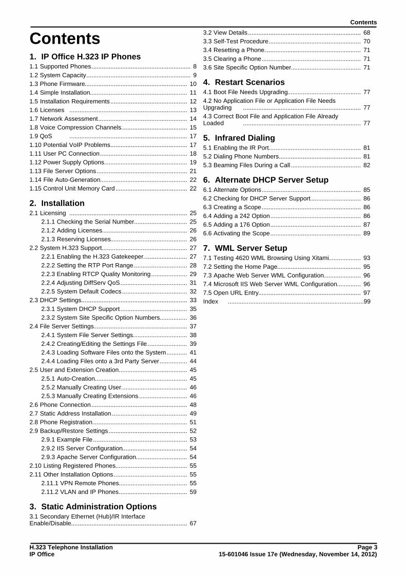
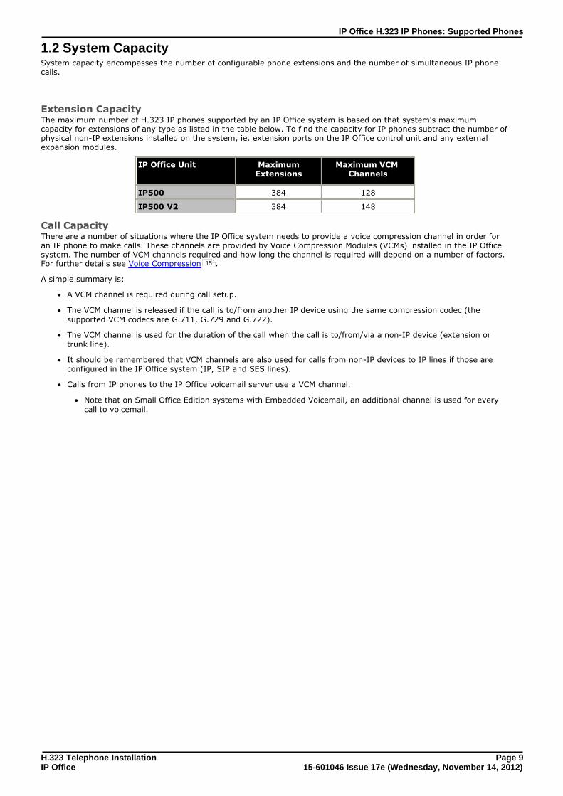
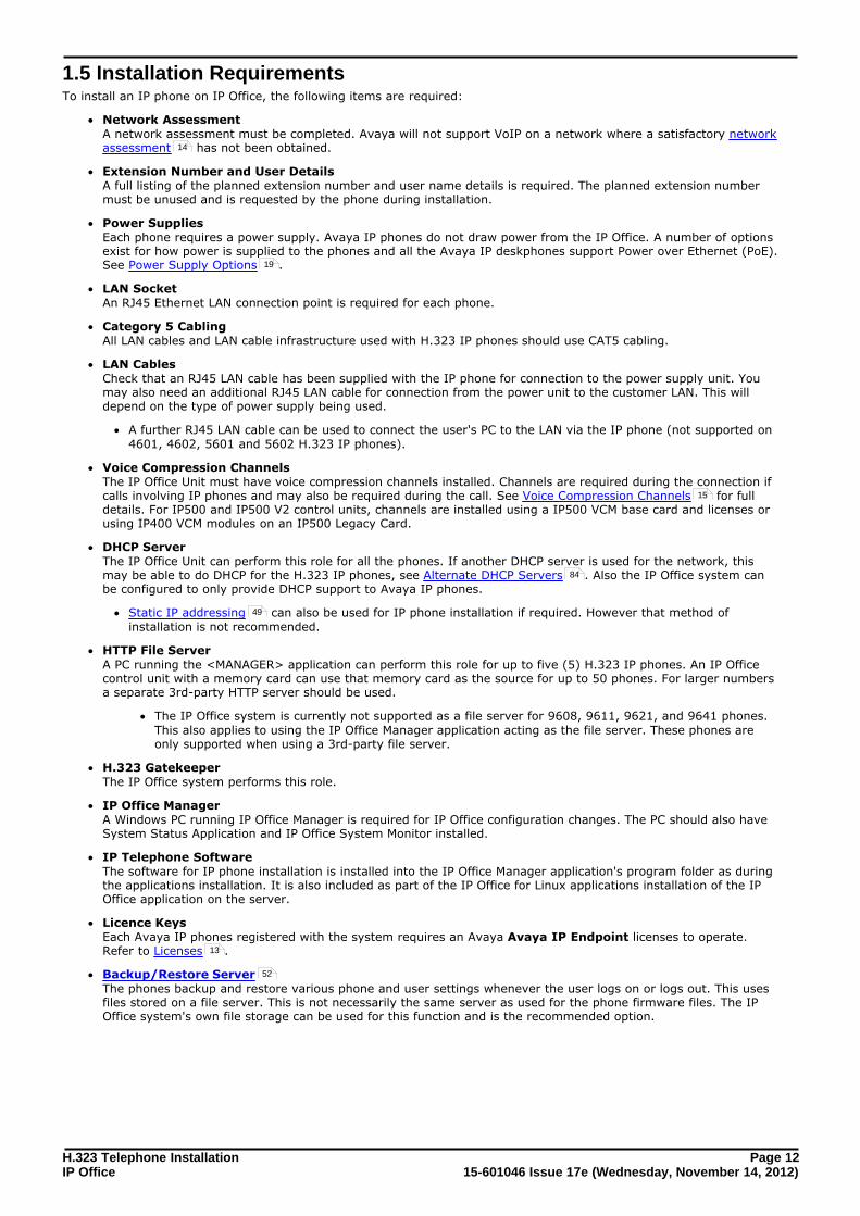