Embed Size (px)
Citation preview
INSTRUCTION MANUAL
H5SDIGITAL TIME SWITCH
Safety PrecautionsP.1
Table of ContentsP.5
OperationP.9
InstallationP.60
Thank you for purchasing this OMRON product. Please read this instruct ion MANUAL and thoroughly familiarize yourself with the functions and characteristics of the product before use. Please retain this MANUAL for future reference.
9966572-0B
MODEL
© All Rights Reserved.
OMRON Corporation
Safety Precautions
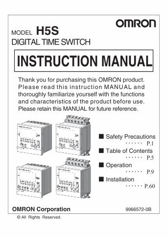
Suitabil i ty for Use
Key to Warning Symbols
CAUTIONIndicates information that, if not followed, could result in relatively serious or minor injury, property damage, or faulty operation.
OMRON shall not be responsible for conformity with any standards, codes, or regulations that apply to the combination of the products in the customer's application or use of the product. Take all necessary steps to determine the suitability of the product for the systems, machines, and equipment with which it will be used. Know and observe all prohibitions of use applicable to this product.NEVER USE THE PRODUCTS FOR AN APPLICATION INVOLVING SERIOUS RISK TO LIFE OR PROPERTY WITHOUT ENSURING THAT THE SYSTEM AS A WHOLE HAS BEEN DESIGNED TO ADDRESS THE RISKS, AND THAT THE OMRON PRODUCT IS PROPERLY RATED AND INSTALLED FOR THE INTENDED USE WITHIN THE OVERALL EQUIPMENT OR SYSTEM.See also Product catalog for Warranty and Limitation of Liability.
- 1 -

Precautionary Information
CAUTIONMinor injury by electrocution may occasionally occur. Do not touch any of the terminals while power is being supplied. Be sure to mount the terminal cover after wiring.When mounting a surface-mounting model on exposure, always install the Y92A-72H terminal cover (separately purchased).
Minor injury due to explosion may occasionally occur. Do not use product where subject to flammable or explosive gas.
Minor electric shock, fire or malfunction may occasionally occur. Never attempt to disassemble, modify, or repair the product or touch any of the internal parts.
Fire may occasionally occur. Tighten the terminal screws to the rated torque (from 0.98 to 1.17N·m).
Unexpected operation may occasionally occur.Before changing times or other settings while power is being supplied, either turn OFF the power on the load side or set the output ON/OFF switch to OFF and confirm the safety of the system.
Minor electric shock, fire, or malfunction may occasionally occur. Do not allow metal fragments or lead wire scraps to fall inside the Time Switch.
If the output relay is used beyond its life expectancy, its contacts may become fused or there may be a risk of fire. Use the output relay within its rated load and electrical life expectancy. The life expectancy of the output relay varies considerably according to its usage.
Serious injury may occasionally occur due to fire or explosion of a battery, or leakage from a battery. Never attempt to short the positive and negative terminals, recharge, disassemble, deform by applying excessive pressure, or expose the battery to fire.
- 2 -
Graphic symbol
Warning against ruptureNotification of possible rupture under certain conditions.
General warningNotification of general, unspecified actions that users must perform.
Prohibition against disassemblyNotification of disassembly of products, when doing so can cause possible electric shock.
General warningNotification of general, unspecified prohibition items.
Warning against electric shockNotification of possible electric shock under certain conditions.
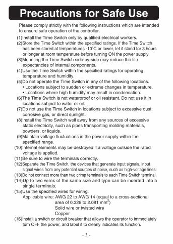
Please comply strictly with the following instructions which are intended to ensure safe operation of the controller.
Precautions for Safe Use
(1)Install the Time Switch only by qualified electrical workers. (2)Store the Time Switch within the specified ratings. If the Time Switch
has been stored at temperatures -10˚C or lower, let it stand for 3 hours or longer at room temperature before turning ON the power supply.
(3)Mounting the Time Switch side-by-side may reduce the life expectancies of internal components.
(4)Use the Time Switch within the specified ratings for operating temperature and humidity.
(5)Do not operate the Time Switch in any of the following locations.• Locations subject to sudden or extreme changes in temperature.• Locations where high humidity may result in condensation.
(6)The Time Switch is not waterproof or oil resistant. Do not use it in locations subject to water or oil.
(7)Do not use the Time Switch in locations subject to excessive dust, corrosive gas, or direct sunlight.
(8)Install the Time Switch well away from any sources of excessive static electricity, such as pipes transporting molding materials, powders, or liquids.
(9)Maintain voltage fluctuations in the power supply within the specified range.
(10)Internal elements may be destroyed if a voltage outside the rated voltage is applied.
(11)Be sure to wire the terminals correctly.(12)Separate the Time Switch, the devices that generate input signals, input
signal wires from any potential sources of noise, such as high-voltage lines.(13)Do not connect more than two crimp terminals to each Time Switch terminal.(14)Up to two wires of the same size and type can be inserted into a
single terminals.(15)Use the specified wires for wiring.
Applicable wire: AWG 22 to AWG 14 (equal to a cross-sectional area of 0.326 to 2.081 mm2)Solid wire or twisted wire
Copper(16)Install a switch or circuit breaker that allows the operator to immediately
turn OFF the power, and label it to clearly indicates its function.
- 3 -
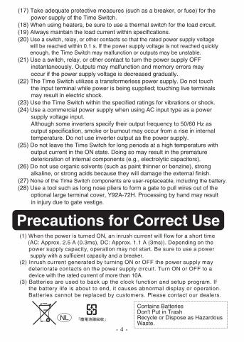
Precautions for Correct Use
(17) Take adequate protective measures (such as a breaker, or fuse) for the power supply of the Time Switch. (18) When using heaters, be sure to use a thermal switch for the load circuit. (19) Always maintain the load current within specifications. (20) Use a switch, relay, or other contacts so that the rated power supply voltage will be reached within 0.1 s. If the power supply voltage is not reached quickly enough, the Time Switch may malfunction or outputs may be unstable. (21) Use a switch, relay, or other contact to turn the power supply OFF instantaneously. Outputs may malfunction and memory errors may occur if the power supply voltage is decreased gradually. (22) The Time Switch utilizes a transformerless power supply. Do not touch the input terminal while power is being supplied; touching live terminals may result in electric shock. (23) Use the Time Switch within the specified ratings for vibrations or shock.(24) Use a commercial power supply when using AC input type as a power supply voltage input. Although some inverters specify their output frequency to 50/60 Hz as output specification, smoke or burnout may occur from a rise in internal temperature. Do not use inverter output as the power supply. (25) Do not leave the Time Switch for long periods at a high temperature with output current in the ON state. Doing so may result in the premature deterioration of internal components (e.g., electrolytic capacitors). (26) Do not use organic solvents (such as paint thinner or benzine), strong alkaline, or strong acids because they will damage the external finish.(27) None of the Time Switch components are user-replaceable, including the battery.(28) Use a tool such as long nose pliers to form a gate to pull wires out of the optional large terminal cover, Y92A-72H. Processing by hand may result in injury due to gate vestige.
(1) When the power is turned ON, an inrush current will flow for a short time (AC: Approx. 2.5 A (0.3ms), DC: Approx. 1.1 A (3ms)). Depending on the power supply capacity, operation may not start. Be sure to use a power supply with a sufficient capacity and a breaker. (2) Inrush current generated by turning ON or OFF the power supply may deteriorate contacts on the power supply circuit. Turn ON or OFF to a device with the rated current of more than 10A. (3) Batteries are used to back up the clock function and setup program. If the battery life is about to end, it causes abnormal display or operation. Batteries cannot be replaced by customers. Please contact our dealers.
- 4 -
NL
Contains BatteriesDon't Put in TrashRecycle or Dispose as Hazardous Waste.
Operation
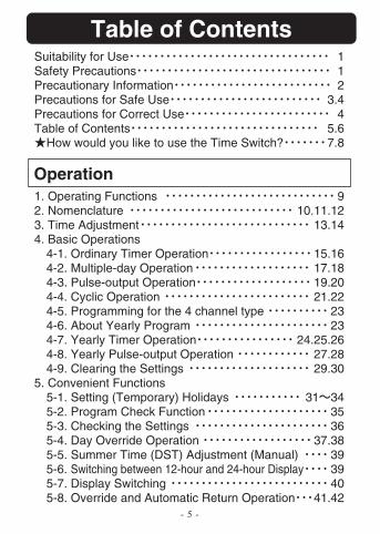
Table of ContentsSuitability for Use 1Safety Precautions 1Precautionary Information 2Precautions for Safe Use 3.4Precautions for Correct Use 4Table of Contents 5.6
How would you like to use the Time Switch? 7.8
1. Operating Functions 92. Nomenclature 10.11.123. Time Adjustment 13.144. Basic Operations
4-1. Ordinary Timer Operation 15.164-2. Multiple-day Operation 17.184-3. Pulse-output Operation 19.204-4. Cyclic Operation 21.224-5. Programming for the 4 channel type 234-6. About Yearly Program 234-7. Yearly Timer Operation 24.25.264-8. Yearly Pulse-output Operation 27.284-9. Clearing the Settings 29.30
5. Convenient Functions5-1. Setting (Temporary) Holidays 31 345-2. Program Check Function 355-3. Checking the Settings 365-4. Day Override Operation 37.385-5. Summer Time (DST) Adjustment (Manual) 395-6. Switching between 12-hour and 24-hour Display 395-7. Display Switching 405-8. Override and Automatic Return Operation 41.42
- 5 -
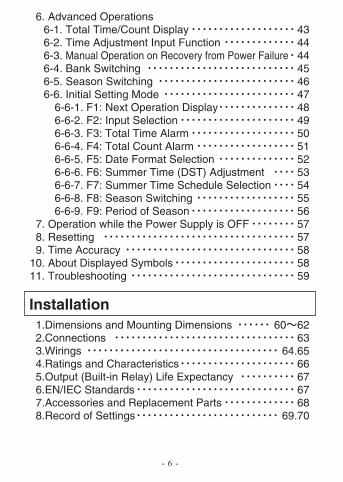
6. Advanced Operations 6-1. Total Time/Count Display 43 6-2. Time Adjustment Input Function 44 6-3. Manual Operation on Recovery from Power Failure 44 6-4. Bank Switching 45 6-5. Season Switching 46 6-6. Initial Setting Mode 47 6-6-1. F1: Next Operation Display 48 6-6-2. F2: Input Selection 49 6-6-3. F3: Total Time Alarm 50 6-6-4. F4: Total Count Alarm 51 6-6-5. F5: Date Format Selection 52 6-6-6. F6: Summer Time (DST) Adjustment 53 6-6-7. F7: Summer Time Schedule Selection 54 6-6-8. F8: Season Switching 55 6-6-9. F9: Period of Season 56 7. Operation while the Power Supply is OFF 57 8. Resetting 57 9. Time Accuracy 5810. About Displayed Symbols 5811. Troubleshooting 59
Installation 1.Dimensions and Mounting Dimensions 60 62 2.Connections 63 3.Wirings 64.65 4.Ratings and Characteristics 66 5.Output (Built-in Relay) Life Expectancy 67 6.EN/IEC Standards 67 7.Accessories and Replacement Parts 68 8.Record of Settings 69.70
- 6 -
How would you like to use the Time Switch?
- 7 -
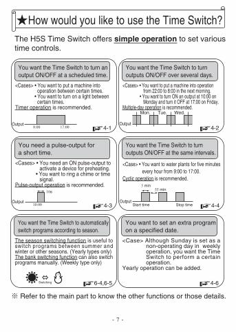
The H5S Time Switch offers simple operation to set various time controls.
You want the Time Switch to turn an output ON/OFF at a scheduled time.
<Cases> • You want to put a machine into operation between certain times.
• You want to turn on a light between certain times.
Timer operation is recommended.
You want the Time Switch to turn outputs ON/OFF over several days.
<Cases> • You want to put a machine into operation from 22:00 to 8:00 in the next morning.
• You want to turn ON an output at 10:00 on Monday and turn it OFF at 17:00 on Friday.
Multiple-day operation is recommended.
You want the Time Switch to turn outputs ON/OFF at the same intervals.
<Case> • You want to water plants for five minutes every hour from 9:00 to 17:00.
Cyclic operation is recommended.
You want to set an extra programon a specified date.
<Case> Although Sunday is set as a non-operating day in weekly operation, you want the Time Switch to perform a certain operation.
Yearly operation can be added.
Refer to the main part to know the other functions or those details.
8:00
Start time Stop time
17:00 4-1 4-2
4-4
4-6
Output Output
You need a pulse-output for a short time.
<Cases> • You need an ON pulse-output to activate a device for preheating.
• You want to ring a chime or time signal.
Pulse-output operation is recommended.
10:00
10s
4-3Output
5 min55 min
Mon. Tue. Wed.
Output
You want the Time Switch to automatically switch programs according to season.
The season switching function is useful to switch programs between summer and winter or other seasons. (Yearly types only)The bank switching function can also switch programs manually. (Weekly type only)
6-4,6-5Switching
- 8 -
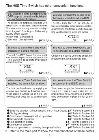
The H5S Time Switch has other convenient functions.
The scheduled outputs are turned OFF temporarily, for example, only on the next Wednesday or during summer holidays from August 13 to August 15 by using holiday setting function.Weekly type : Day specifiedYearly type : Date specified
You want to monitor the periods for or the times at which load is turned ON.
T h e H 5 S T i m e S w i t c h f e a t u r e s t o t a l time/count display with alarm (except for 4 channel type). This feature is useful to ensure long load life including lamps and moters.
The set ON/OFF times for one week can be displayed in the sequence the Time Switch is to operate by program check function.
You want to check the programs set for Wednesday in a simple manner.
Checking mode is useful to check the programs set for a particular day.
When several Time Switches are installed, the time is fast or slow.
The time can be adjusted by applying an external input (except for 4 channel type).When group-mounting two or more Time Switches, their times can be synchronized.
You want to use the Time Switch in summer time (DST) zone.
You can change the time to summer t i m e ( 1 h o u r a h e a d ) s i m p l y b y pressing a Key. Automatic summer time adjustment is possible for yearly type.
Refer to the main part to know the other functions or those details.
Switching between 12-hour (am/pm) and 24-hour Display Refer to Section 5-67-5 noitceS ot refeRgnihctiws yalpsiD
Override and automatic return operation Refer to Section 5-84-5 noitceS ot refeRnoitarepo edirrevo yaD1-6-6 noitceS ot refeRyalpsid noitarepo txeN5-6-6 noitceS ot refeRnoitceles tamrof etaD
Manual operation on recovery from power failure Refer to Section 6-3
5-1 6-1
5-2 5-3
6-2 6-6-6
SUN MON TUE WED THU FRI SAT SUN MON TUE WED THU FRI SAT
You want the Time Switch to turn OFF outputs on national holidays or unscheduled holidays.
You want to check the set one-week programs in a simple manner.
Operation1. Operating Functions
- 9 -
Weekly2 chnls
Yearly2 chnls
Yearly4 chnls
Weekly2 chnls
Yearly2 chnls
Yearly4 chnls
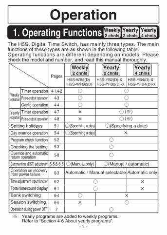
The H5S, Digital Time Switch, has mainly three types. The main functions of these types are as shown in the following table.Operating functions are different depending on models. Please check the model and number, and read this manual thoroughly.
Setting holidays
Day override operation
Program check function
Checking the settingOverride and automatic return operation
Summer time (DST) adjustmentOperation on recovery from power failure
Time adjustment input function
Total time/count display
Bank switching
Season switching
Operation during power OFF
Automatic / Manual selectable Automatic only
(Specifying a day)
(Specifying a day)
(Manual only)
4-1,4-2
4-3
4-4
4-7
4-8
5-1
5-4
5-2
5-3
5-8
5-5,6-6-6
6-3
6-2
6-1
6-4
6-5
7
(Specifying a date)
(Manual / automatic)
Timer operation
Pulse-output operation
Cyclic operation
Timer operation
Pulse-output operation
Weekly operation
PagesH5S-WB2(D)H5S-WFB2(D)
H5S-YB2(D)-XH5S-YFB2(D)-X
H5S-YB4(D)-XH5S-YFB4(D)-X
Yearly operation
Yearly programs are added to weekly programs.Refer to “Section 4-6 About yearly programs”.
- 10 -
2. Nomenclature Weekly2 chnls
Yearly2 chnls
Yearly4 chnls
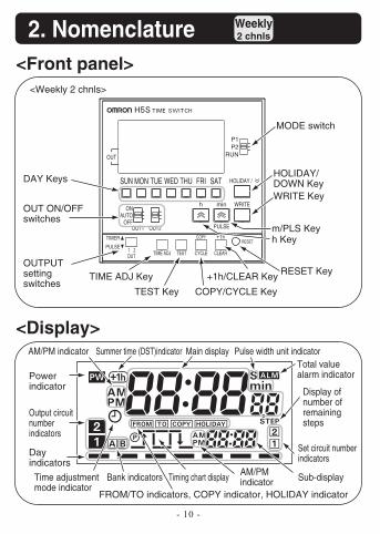
<Front panel>
<Display>
<Weekly 2 chnls>
RESET
TEST
COPY
CYCLE CLEARTIME ADJOUT
PULSE
TIMER
HOLIDAY /
ONAUTO
OFF
OUT
SATFRITHUWEDTUEMONSUN
P2P1
RUN
PULSE
h min WRITE
OUT1 OUT2
RESET Key
DAY Keys
Power indicator
Day indicators
Output circuit number indicators
FROM/TO indicators, COPY indicator, HOLIDAY indicator
AM/PM indicator Summer time (DST)indicator Main display Pulse width unit indicatorTotal value alarm indicator
Sub-displayAM/PM indicatorTiming chart displayBank indicatorsTime adjustment
mode indicator
Display of number of remaining steps
Set circuit number indicators
TIME ADJ Key
OUT ON/OFF switches
MODE switch
HOLIDAY/DOWN KeyWRITE Key
m/PLS Keyh Key
+1h/CLEAR Key
COPY/CYCLE KeyTEST Key
OUTPUT setting switches
- 11 -
2. Nomenclature Weekly2 chnls
Yearly2 chnls
Yearly4 chnls
<Front panel>
<Display>
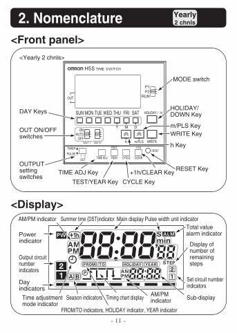
<Yearly 2 chnls>
ONAUTO
OFF
OUT
OUT1 OUT2TEST
YEAR
RESET
CYCLE CLEARTIME ADJOUT
PULSE
TIMER
DMY
WRITEm/PLSh
P2P1
RUN
HOLiDAY /SATFRITHUWEDTUEMONSUNDAY Keys
FROM/TO indicators, HOLIDAY indicator, YEAR indicator
Pulse width unit indicatorTotal value alarm indicator
Season indicators
TIME ADJ Key
OUT ON/OFF switches
MODE switch
HOLIDAY/DOWN Key
WRITE Key
h Key
+1h/CLEAR Key
CYCLE KeyTEST/YEAR Key
OUTPUT setting switches
RESET Key
m/PLS Key
Display of number of remaining steps
Power indicator
Day indicators
Output circuit number indicators
Sub-displayAM/PM indicatorTiming chart displayTime adjustment
mode indicator
Set circuit number indicators
AM/PM indicator Summer time (DST)indicator Main display
- 12 -
2. Nomenclature Weekly2 chnls
Yearly2 chnls
Yearly4 chnls
<Front panel>
<Display>
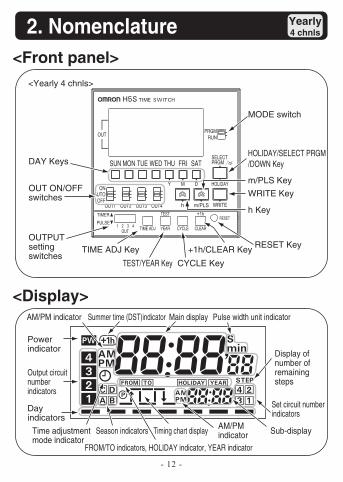
<Yearly 4 chnls>
OUT
SELECTPRGM
ONAUTO
OFF
DMY
WRITEm/PLSh
HOLIDAY
OUT2OUT1 OUT4OUT3
SATFRITHUWEDTUEMONSUN
TEST
CYCLE CLEAR
RESET
YEARTIME ADJOUT
PULSE
TIMER
RUNPRGM
DAY Keys
FROM/TO indicators, HOLIDAY indicator, YEAR indicator
Power indicator
Day indicators
Output circuit number indicators
AM/PM indicator Summer time (DST)indicator Main display Pulse width unit indicator
Sub-displayTime adjustment mode indicator
Display of number of remaining steps
Set circuit number indicators
Season indicators
OUT ON/OFF switches
MODE switch
HOLIDAY/SELECT PRGM/DOWN Key
WRITE Key
m/PLS Key
h Key
CYCLE KeyTEST/YEAR Key
OUTPUT setting switches
RESET KeyTIME ADJ Key +1h/CLEAR Key
AM/PM indicatorTiming chart display
3. Time Adjustment
- 13 -
Weekly2 chnls
Yearly2 chnls
Yearly4 chnls
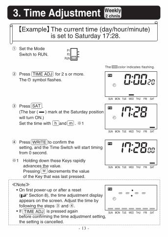
Example The current time (day/hour/minute) is set to Saturday 17:28.
SUN MON TUE WED THU FRI SAT
SUN MON TUE WED THU FRI SAT
SUN MON TUE WED THU FRI SAT
SUN MON TUE WED THU FRI SAT
The color indicates flashing.
Set the Mode Switch to RUN.
1 Holding down these Keys rapidly advances the value.Pressing decrements the value of the Key that was last pressed.
Note • On first power-up or after a reset
( Section 8), the time adjustment display appears on the screen. Adjust the time by following the steps and .
• If is pressed again before confirming the time adjustment setting, the setting is cancelled.
P1P2
RUN
Press for 2 s or more.The symbol flashes.
TIME ADJ
TIME ADJ
Press . (The bar ( ) mark at the Saturday position will turn ON.) Set the time with and . 1 h
SAT
m
Press to confirm the setting, and the Time Switch will start timing from 0 second.
WRITE
3. Time Adjustment
- 14 -
Weekly2 chnls
Yearly2 chnls
Yearly4 chnls
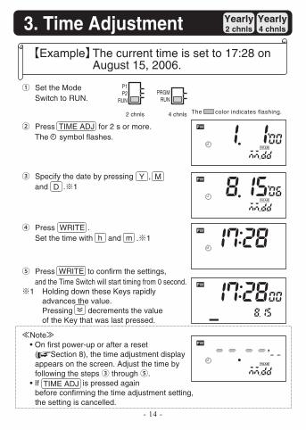
Example The current time is set to 17:28 on August 15, 2006.
Set the Mode Switch to RUN.
Specify the date by pressing , and . 1
Press .Set the time with and . 1
Press to confirm the settings, and the Time Switch will start timing from 0 second.
2 chnls
P1P2
RUN
4 chnls
PRGMRUN
Y M D
WRITE
WRITE
The color indicates flashing.
Press for 2 s or more.The symbol flashes.
TIME ADJ
h m
1 Holding down these Keys rapidly advances the value.Pressing decrements the value of the Key that was last pressed.
Note • On first power-up or after a reset
( Section 8), the time adjustment display appears on the screen. Adjust the time by following the steps through .
• If is pressed again before confirming the time adjustment setting, the setting is cancelled.
TIME ADJ
4. Basic Operations
- 15 -
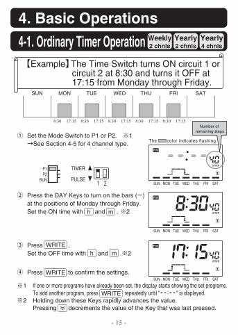
4-1. Ordinary Timer Operation Weekly2 chnls
Yearly2 chnls
Yearly4 chnls
Example The Time Switch turns ON circuit 1 or circuit 2 at 8:30 and turns it OFF at 17:15 from Monday through Friday.
Set the Mode Switch to P1 or P2. 1 See Section 4-5 for 4 channel type.
Press the DAY Keys to turn on the bars ( ) at the positions of Monday through Friday.Set the ON time with and . 2
Press to confirm the settings.
P1P2
RUN
SUN MON TUE WED THU FRI SAT
8:30 17:15 8:30 17:15 8:30 17:15 8:30 17:15 8:30 17:15Number of
remaining steps
The color indicates flashing.
SUN MON TUE WED THU FRI SAT
SUN MON TUE WED THU FRI SAT
SUN MON TUE WED THU FRI SAT
PULSE
TIMER
h m
Press .Set the OFF time with and . 2
WRITE
WRITE
h m
1 If one or more programs have already been set, the display starts showing the set programs.To add another program, press repeatedly until "--:--" is displayed.
2 Holding down these Keys rapidly advances the value.Pressing decrements the value of the Key that was last pressed.
WRITE
- 16 -
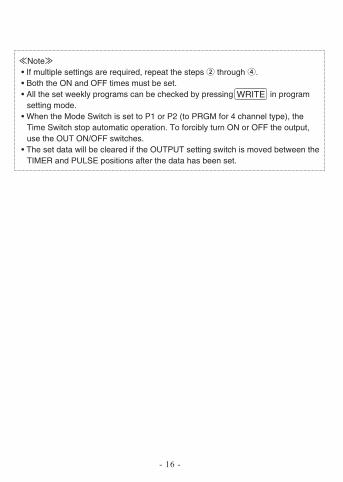
Note • If multiple settings are required, repeat the steps through . • Both the ON and OFF times must be set. • All the set weekly programs can be checked by pressing in program
setting mode. • When the Mode Switch is set to P1 or P2 (to PRGM for 4 channel type), the
Time Switch stop automatic operation. To forcibly turn ON or OFF the output, use the OUT ON/OFF switches.
• The set data will be cleared if the OUTPUT setting switch is moved between the TIMER and PULSE positions after the data has been set.
WRITE
- 17 -
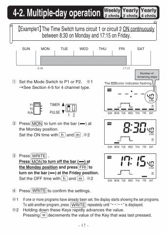
4-2. Multiple-day operation Weekly2 chnls
Yearly2 chnls
Yearly4 chnls
Press to turn on the bar ( ) at the Monday position.Set the ON time with and . 2
Press to confirm the settings.
51:7103:8Number of
remaining steps
Example1 The Time Switch turns circuit 1 or circuit 2 ON continuously between 8:30 on Monday and 17:15 on Friday.
Press . Press to turn off the bar ( ) at the Monday position and press to turn on the bar ( ) at the Friday position.Set the OFF time with and . 2
MON
MONFRI
SUN MON TUE WED THU FRI SAT
The color indicates flashing.Set the Mode Switch to P1 or P2. 1 See Section 4-5 for 4 channel type.
P1P2
RUN PULSE
TIMER
h m
h m
WRITE
WRITE
1 If one or more programs have already been set, the display starts showing the set programs.To add another program, press repeatedy until "--:--" is displayed.
2 Holding down these Keys rapidly advances the value.Pressing decrements the value of the Key that was last pressed.
SUN MON TUE WED THU FRI SAT
SUN MON TUE WED THU FRI SAT
SUN MON TUE WED THU FRI SAT
WRITE
- 18 -
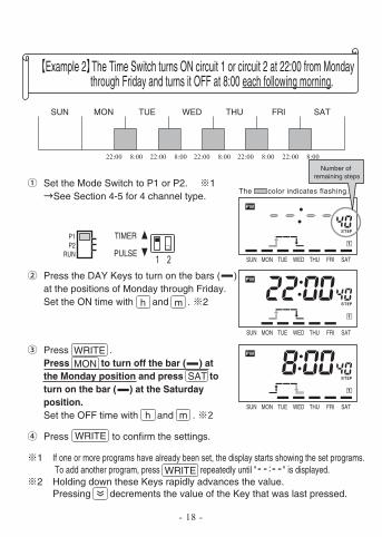
Set the Mode Switch to P1 or P2. 1See Section 4-5 for 4 channel type.
Press the DAY Keys to turn on the bars ( ) at the positions of Monday through Friday.Set the ON time with and . 2
22:00 8:00 22:00 8:00 22:00 8:00 22:00 8:00 22:00 8:00Number of
remaining steps
Example 2 The Time Switch turns ON circuit 1 or circuit 2 at 22:00 from Monday through Friday and turns it OFF at 8:00 each following morning.
SUN MON TUE WED THU FRI SAT
P1P2
RUN PULSE
TIMER
The color indicates flashing.
SUN MON TUE WED THU FRI SAT
SUN MON TUE WED THU FRI SAT
SUN MON TUE WED THU FRI SAT
h m
Press . Press to turn off the bar ( ) at the Monday position and press to turn on the bar ( ) at the Saturday position.Set the OFF time with and .
MONSAT
h m
WRITE
Press to confirm the settings.WRITE
1 If one or more programs have already been set, the display starts showing the set programs. To add another program, press repeatedly until "--:--" is displayed.
2 Holding down these Keys rapidly advances the value.Pressing decrements the value of the Key that was last pressed.
WRITE
- 19 -
AM8:25
30s
Number of remaining steps
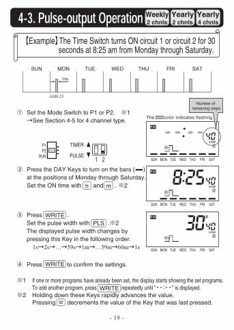
Example The Time Switch turns ON circuit 1 or circuit 2 for 30 seconds at 8:25 am from Monday through Saturday.
Press .Set the pulse width with . 2The displayed pulse width changes by pressing this Key in the following order.
1s 2s … 59s 1m …59m 60m 1s
Weekly2 chnls
Yearly2 chnls
Yearly4 chnls
SUN MON TUE WED THU FRI SAT
The color indicates flashing.
SUN MON TUE WED THU FRI SAT
SUN MON TUE WED THU FRI SAT
SUN MON TUE WED THU FRI SAT
Set the Mode Switch to P1 or P2. 1 See Section 4-5 for 4 channel type.
P1P2
RUN PULSE
TIMER
Press the DAY Keys to turn on the bars ( ) at the positions of Monday through Saturday.Set the ON time with and . 2 h m
WRITEPLS
Press to confirm the settings.WRITE
1 If one or more programs have already been set, the display starts showing the set programs.To add another program, press repeatedly until "--:--" is displayed.
2 Holding down these Keys rapidly advances the value.Pressing decrements the value of the Key that was last pressed.
WRITE
- 20 -
Note • If multiple settings are required, repeat the steps through . • Both the ON time and pulse width must be set. • All the set weekly programs can be checked by pressing in program
setting mode. • When the Mode Switch is set to P1 or P2 (to PRGM for 4 channel type), the
Time Switch stops automatic operation. To forcibly turn ON or OFF the output, use the OUT ON/OFF switches.
• The set data will be cleared if the OUTPUT setting switch is moved between the TIMER and PULSE positions after the data has been set.
WRITE
- 21 -
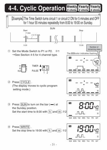
Set the Mode Switch to P1 or P2. 1 See Section 4-5 for 4 channel type.
Press .(The display moves to cyclic program setting mode.)
Press .Set the stop time to 19:00 with and . 2
SUN
8:00
Start
1 h 55 min5 min
Number of remaining steps
Example The Time Switch turns circuit 1 or circuit 2 ON for 5 minutes and OFF for 1 hour 55 minutes repeatedly from 8:00 to 19:00 on Sunday.
Press to turn on the bar ( ) at the Sunday position.Set the start time to 8:00 with and . 2
4-4. Cyclic Operation Weekly2 chnls
Yearly2 chnls
Yearly4 chnls
19:00
Stop
CYCLE
SUN
P1P2
RUN PULSE
TIMER
The color indicates flashing.
SUN MON TUE WED THU FRI SAT
SUN MON TUE WED THU FRI SAT
SUN MON TUE WED THU FRI SAT
SUN MON TUE WED THU FRI SAT
h
h
m
mWRITE
- 22 -
Note • If multiple settings are required, repeat the steps through . • • All the set weekly programs can be checked by pressing in program
setting mode. • When the Mode Switch is set to P1 or P2 (to PRGM for 4 channel type), the
Time Switch stops automatic operation. To forcibly turn ON or OFF the output, use the OUT ON/OFF switches.
• Set Cyclic operation so as not to overlap other operations in individual circuits. • The set data will be cleared if the OUTPUT setting switch is moved between the
TIMER and PULSE positions after the data has been set.
SUN MON TUE WED THU FRI SAT
SUN MON TUE WED THU FRI SAT
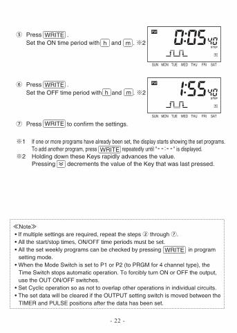
Press .Set the ON time period with and . 2 h m
WRITE
Press .Set the OFF time period with and . 2 h m
WRITE
Press to confirm the settings.WRITE
WRITE
1 If one or more programs have already been set, the display starts showing the set programs.To add another program, press repeatedly until "--:--" is displayed.
2 Holding down these Keys rapidly advances the value.Pressing decrements the value of the Key that was last pressed.
WRITE
- 23 -
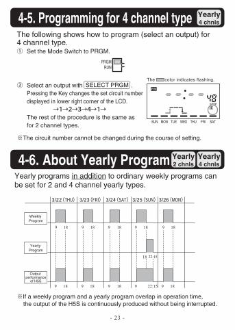
Set the Mode Switch to PRGM.
The circuit number cannot be changed during the course of setting.
The following shows how to program (select an output) for 4 channel type.
Select an output with .Pressing the Key changes the set circuit number displayed in lower right corner of the LCD.
The rest of the procedure is the same as for 2 channel types.
Weekly2 chnls
Yearly2 chnls
Yearly4 chnls
PRGMRUN
4-5. Programming for 4 channel type
SELECT PRGM
Yearly programs in addition to ordinary weekly programs can be set for 2 and 4 channel yearly types.
Weekly2 chnls
Yearly2 chnls
Yearly4 chnls4-6. About Yearly Program
The color indicates flashing.
SUN MON TUE WED THU FRI SAT
If a weekly program and a yearly program overlap in operation time, the output of the H5S is continuously produced without being interrupted.
818181
18
18
22:15
Output performance
of H5S
9 9 189 9 9
8151:2281819 9 189 9 9
- 24 -
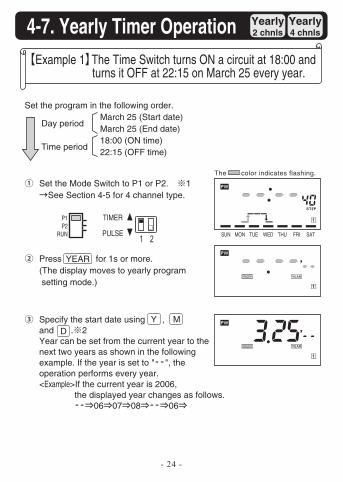
Set the Mode Switch to P1 or P2. 1 See Section 4-5 for 4 channel type.
Set the program in the following order.March 25 (Start date)March 25 (End date)18:00 (ON time)22:15 (OFF time)
Press for 1s or more.(The display moves to yearly program setting mode.)
Example 1 The Time Switch turns ON a circuit at 18:00 and turns it OFF at 22:15 on March 25 every year.
Specify the start date using , and . 2Year can be set from the current year to the next two years as shown in the following example. If the year is set to "--", the operation performs every year.<Example>If the current year is 2006,
the displayed year changes as follows.-- 06 07 08 -- 06
Weekly2 chnls
Yearly2 chnls
Yearly4 chnls
Day period
Time period
YEAR
4-7. Yearly Timer Operation
The color indicates flashing.
SUN MON TUE WED THU FRI SAT
P1P2
RUN PULSE
TIMER
Y M D
- 25 -
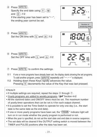
Press .Set the ON time with and . 2
Press to confirm the settings.
Press .Specify the end date using , and . 2If the starting year has been set to "--", the ending year cannot be set.
Number of remaining steps
Note • If multiple settings are required, repeat the steps through . • •
• It is possible to set the Time Switch to operate for only one day (i.e., the start date is the same date as the end date).
• If one or more yearly programs have been set, the " " indicator light will turn on in run mode whether the yearly program is performed or not.
• • The set data will be cleared if the OUTPUT setting switch is moved between the
TIMER and PULSE positions after the data has been set.
Y M
h m
D
WRITE
WRITE
Press .Set the OFF time with and . 2 h m
WRITE
WRITE
1 If one or more programs have already been set, the display starts showing the set programs.To add another program, press repeatedly until "--.--" is displayed.
2 Holding down these Keys rapidly advances the value.Pressing decrements the value of the Key that was last pressed.
WRITE
- 26 -
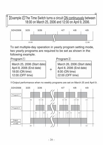
To set multiple-day operation in yearly program setting mode, two yearly programs are required to be set as shown in the following example.
3/24/2006 3/25 3/26 4/7 4/8 4/9
00:2100:81
Example 2 The Time Switch turns a circuit ON continuously between 18:00 on March 25, 2006 and 12:00 on April 9, 2006.
March 25, 2006 (Start date)April 8, 2006 (End date)18:00 (ON time)12:00 (OFF time)
March 26, 2006 (Start date)April 8, 2006 (End date)8:00 (ON time)22:00 (OFF time)
Program Program
3/24/2006 3/25 3/26 4/7 4/8 4/9
18 12 18 12 18 12 18 12
Program
8 22 8 22 8 22
Program
2181
Output performance when no weekly programs are set on March 25 and April 9.
Output performance
of H5S
- 27 -
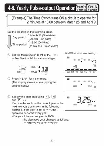
Example The Time Switch turns ON a circuit to operate for 2 minutes at 18:00 between March 25 and April 9.
Weekly2 chnls
Yearly2 chnls
Yearly4 chnls4-8. Yearly Pulse-output Operation
The color indicates flashing.
SUN MON TUE WED THU FRI SAT
Set the program in the following order.March 25 (Start date)April 9 (End date)18:00 (ON time)2 minutes (Pulse width)
Day period
Time period
Set the Mode Switch to P1 or P2. 1 See Section 4-5 for 4 channel type.
P1P2
RUN PULSE
TIMER
Press for 1 s or more.(The display moves to yearly program setting mode.)
YEAR
Specify the start date using , and . 2Year can be set from the current year to the next two years as shown in the following example. If the year is set to "--", the operation performs every year.<Example> If the current year is 2006,
the displayed year changes as follows.-- 06 07 08 -- 06
Y M D
- 28 -
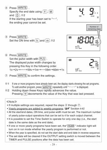
The displayed pulse width changes by pressing this Key in the following order.
Note • If multiple settings are required, repeat the steps through . • Yearly programs are added to weekly programs. 4-6 • All the start/end dates, ON time, and pulse width must be set. The maximum number
of yearly pulse-output operations that can be set is 4 for each output channel. • It is possible to set the Time Switch to operate for only one day (i.e., the start
date is the same date as the end date). • If one or more yearly programs have been set, the" " indicator light will
turn on in run mode whether the yearly program is performed or not. • When the year is specified, do not set the start date and end date in reverse sequence. • The set data will be cleared if the OUTPUT setting switch is moved between the
TIMER and PULSE positions after the data has been set.
Number of remaining steps
Press .Specify the end date using , and . 2If the starting year has been set to "--", the ending year cannot be set.
Y MD
WRITE
Press .Set the ON time with and . 2 h m
WRITE
WRITE
Press to confirm the settings.WRITE
1 If one or more programs have already been set, the display starts showing the set programs.To add another program, press repeatedly until "--.--" is displayed.
2 Holding down these Keys rapidly advances the value.Pressing decrements the value of the Key that was last pressed.
WRITE
- 29 -
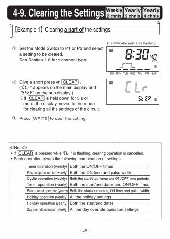
Set the Mode Switch to P1 or P2 and select a setting to be cleared.See Section 4-5 for 4 channel type.
Example 1 Clearing a part of the settings.
Give a short press on .("clr" appears on the main display and "step" on the sub-display.)
If is held down for 3 s or more, the display moves to the mode for clearing all the settings of the circuit.
Press to clear the setting.
Weekly2 chnls
Yearly2 chnls
Yearly4 chnls
Note • If is pressed while "clr" is flashing, clearing operation is cancelled. • Each operation clears the following combination of settings.
Timer operation (weekly) Both the ON/OFF times
Pulse-output operation (weekly) Both the ON time and pulse width
Cyclic operation (weekly) Both the start/stop times and ON/OFF time periods
Timer operation (yearly) Both the start/end dates and ON/OFF times
Pulse-output operation (yearly) Both the start/end dates, ON time and pulse width
Holiday operation (weekly) All the holiday settings
Holiday operation (yearly) Both the start/end dates
Day override operation (weekly) All the day override operation settings
CLEAR
CLEAR
CLEAR
4-9. Clearing the Settings
The color indicates flashing.
SUN MON TUE WED THU FRI SAT
WRITE
- 30 -
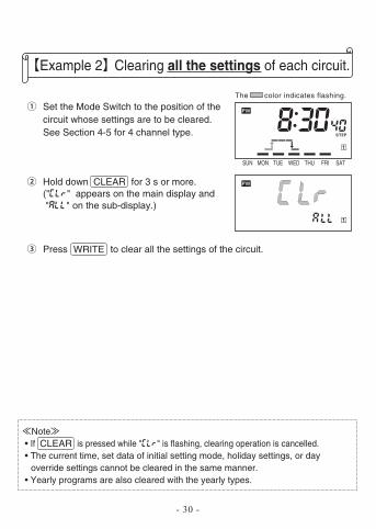
Example 2 Clearing all the settings of each circuit.
Press to clear all the settings of the circuit.
Note • If is pressed while "clr" is flashing, clearing operation is cancelled. • The current time, set data of initial setting mode, holiday settings, or day
override settings cannot be cleared in the same manner. • Yearly programs are also cleared with the yearly types.
The color indicates flashing.
SUN MON TUE WED THU FRI SAT
Set the Mode Switch to the position of the circuit whose settings are to be cleared.See Section 4-5 for 4 channel type.
Hold down for 3 s or more.("clr" appears on the main display and "all" on the sub-display.)
CLEAR
WRITE
CLEAR
5. Convenient Functions
- 31 -
Weekly2 chnls
Yearly2 chnls
Yearly4 chnls
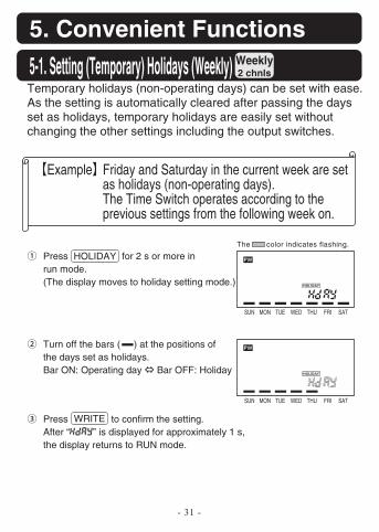
Example Friday and Saturday in the current week are set as holidays (non-operating days). The Time Switch operates according to the previous settings from the following week on.
Press for 2 s or more in run mode.(The display moves to holiday setting mode.)
Temporary holidays (non-operating days) can be set with ease.As the setting is automatically cleared after passing the days set as holidays, temporary holidays are easily set without changing the other settings including the output switches.
Turn off the bars ( ) at the positions of the days set as holidays.Bar ON: Operating day Bar OFF: Holiday
Press to confirm the setting.After “hday” is displayed for approximately 1 s, the display returns to RUN mode.
HOLIDAY
WRITE
5-1. Setting (Temporary) Holidays (Weekly)
The color indicates flashing.
SUN MON TUE WED THU FRI SAT
SUN MON TUE WED THU FRI SAT
- 32 -
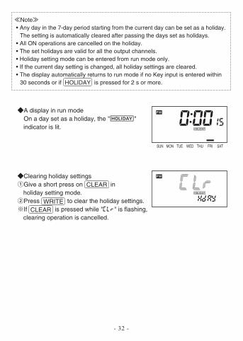
Clearing holiday settingsGive a short press on in holiday setting mode.Press to clear the holiday settings.If is pressed while "clr" is flashing, clearing operation is cancelled.
A display in run modeOn a day set as a holiday, the " " indicator is lit.
Note • Any day in the 7-day period starting from the current day can be set as a holiday.
The setting is automatically cleared after passing the days set as holidays. • All ON operations are cancelled on the holiday. • The set holidays are valid for all the output channels. • Holiday setting mode can be entered from run mode only. • If the current day setting is changed, all holiday settings are cleared. • The display automatically returns to run mode if no Key input is entered within
30 seconds or if is pressed for 2 s or more.HOLIDAY
SUN MON TUE WED THU FRI SAT
CLEAR
CLEARWRITE
- 33 -
Weekly2 chnls
Yearly2 chnls
Yearly4 chnls
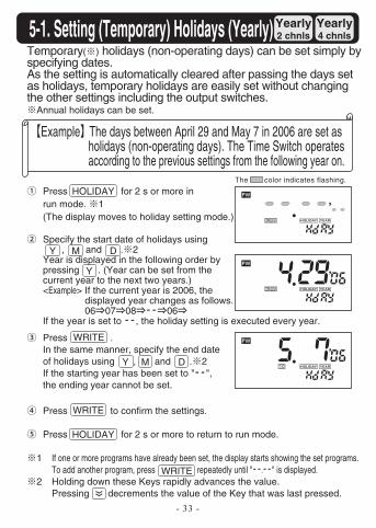
Example The days between April 29 and May 7 in 2006 are set as holidays (non-operating days). The Time Switch operates according to the previous settings from the following year on.
Temporary( ) holidays (non-operating days) can be set simply by specifying dates.As the setting is automatically cleared after passing the days set as holidays, temporary holidays are easily set without changing the other settings including the output switches.
Annual holidays can be set.
Specify the start date of holidays using , and . 2Year is displayed in the following order by pressing . (Year can be set from the current year to the next two years.)<Example> If the current year is 2006, the
displayed year changes as follows.06 07 08 -- 06
If the year is set to --, the holiday setting is executed every year.
Press .In the same manner, specify the end date of holidays using , and . 2If the starting year has been set to "--", the ending year cannot be set.
Press to confirm the settings.
Press for 2 s or more to return to run mode.
1 If one or more programs have already been set, the display starts showing the set programs.To add another program, press repeatedly until "--.--" is displayed.
2 Holding down these Keys rapidly advances the value.Pressing decrements the value of the Key that was last pressed.
5-1. Setting (Temporary) Holidays (Yearly)
Y
Y
Y
M
M
D
D
The color indicates flashing.
Press for 2 s or more in run mode. 1(The display moves to holiday setting mode.)
HOLIDAY
HOLIDAY
WRITE
WRITE
WRITE
- 34 -
Clearing the holiday settings<Clearing a part of holiday settings>
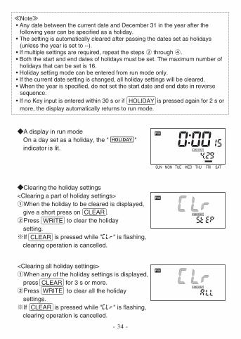
When the holiday to be cleared is displayed, give a short press on .Press to clear the holiday setting.If is pressed while "clr" is flashing, clearing operation is cancelled.
<Clearing all holiday settings>When any of the holiday settings is displayed, press for 3 s or more.Press to clear all the holiday settings.If is pressed while "clr" is flashing, clearing operation is cancelled.
A display in run modeOn a day set as a holiday, the " " indicator is lit.
Note • Any date between the current date and December 31 in the year after the
following year can be specified as a holiday. • The setting is automatically cleared after passing the dates set as holidays
(unless the year is set to --). • If multiple settings are required, repeat the steps through . • Both the start and end dates of holidays must be set. The maximum number of
holidays that can be set is 16. • Holiday setting mode can be entered from run mode only. • If the current date setting is changed, all holiday settings will be cleared. •
• If no Key input is entered within 30 s or if is pressed again for 2 s or more, the display automatically returns to run mode.
HOLIDAY
SUN MON TUE WED THU FRI SAT
CLEAR
CLEAR
CLEAR
CLEAR
WRITE
WRITE
- 35 -
Weekly2 chnls
Yearly2 chnls
Yearly4 chnls
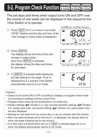
Press for 2 s or more in run mode.(“test” flashes and the day and time of the next change in output state is displayed.)
The set days and times when output turns ON and OFF over the course of one week can be displayed in the sequence the Time Switch is to operate.
Press .The display shows the time of the next change in output state.Each time is pressed, the display shows the days and timesfor one week.
If is pressed while displaying the last setting for the week, “end” is displayed for 2 s and the Time Switch automatically returns to run mode.
Note • Output is not turned ON or OFF according to displays in program check mode
but according to settings and the current time. • Program check mode can be entered from run mode only. • Holiday settings ( 5-1), day override operation settings (
5-4 weekly type only), and yearly settings ( 4-6 yearly types only) are also displayed.
• Settings for one week from the current day on can be checked with this function. • After one-week schedule set for the circuit 1 is displayed, the display starts to
show one-week schedule set for the circuit 2. • If no Key input is entered within 30 s or if is pressed again for 2 s or
more, the display automatically returns to run mode.
TEST
5-2. Program Check Function
The color indicates flashing.
SUN MON TUE WED THU FRI SAT
SUN MON TUE WED THU FRI SAT
WRITE
WRITE
WRITE
TEST
- 36 -
Weekly2 chnls
Yearly2 chnls
Yearly4 chnls
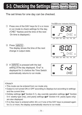
Press one of the DAY keys for 2 s or more in run mode to check settings for the day.(“chec” flashes and the time of the next On time is displayed.)
The set times for one day can be checked.
Press .The display shows the time of the next change in output state.
If is pressed with the last setting of the day displayed, “end” is displayed for 2 s before the Time Switch automatically returns to run mode.
Note • This mode can be entered from run mode only. • Output is not turned ON or OFF according to displays but according to settings
and the current time. • Holiday settings ( 5-1), day override operation settings (
5-4 weekly type only), and yearly settings ( 4-6 yearly types only) are also displayed.
• If no Key input is entered within 30 s or if one of the DAY keys is pressed again for 2 s or more, the display automatically returns to run mode.
5-3. Checking the Settings
The color indicates flashing.
SUN MON TUE WED THU FRI SAT
SUN MON TUE WED THU FRI SAT
WRITE
WRITE
- 37 -
Weekly2 chnls
Yearly2 chnls
Yearly4 chnls
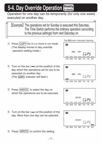
Example The operations set for Sunday is executed this Saturday. The Time Switch performs the ordinary operation (according to the previous settings) from next Saturday on.
Press for 2 s or more in run mode.(The display moves to day override operation setting mode.)
Operation for one day can be temporarily (for only one week) executed on another day.
Press to confirm the setting.
Turn on the bar ( ) at the position of the day which the operations set for are to be executed on another day.(The indicator will flash.)
Press to select the day on which the operations are to be executed.
COPY
Turn on the bar ( ) at the position of the day. More than one day can be selected.
5-4. Day Override Operation
The color indicates flashing.
SUN MON TUE WED THU FRI SAT
SUN MON TUE WED THU FRI SAT
SUN MON TUE WED THU FRI SAT
SUN MON TUE WED THU FRI SAT
WRITE
WRITE
- 38 -
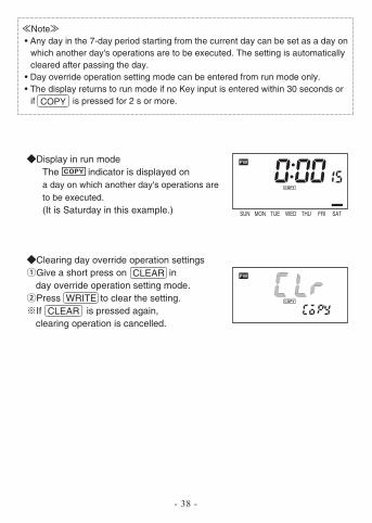
Clearing day override operation settingsGive a short press on in day override operation setting mode.Press to clear the setting.If is pressed again, clearing operation is cancelled.
Display in run modeThe indicator is displayed on a day on which another day's operations are to be executed.(It is Saturday in this example.)
Note • Any day in the 7-day period starting from the current day can be set as a day on
which another day's operations are to be executed. The setting is automatically cleared after passing the day.
• Day override operation setting mode can be entered from run mode only. • The display returns to run mode if no Key input is entered within 30 seconds or
if is pressed for 2 s or more.
CLEAR
CLEAR
COPY
SUN MON TUE WED THU FRI SAT
WRITE
- 39 -
Weekly2 chnls
Yearly2 chnls
Yearly4 chnls
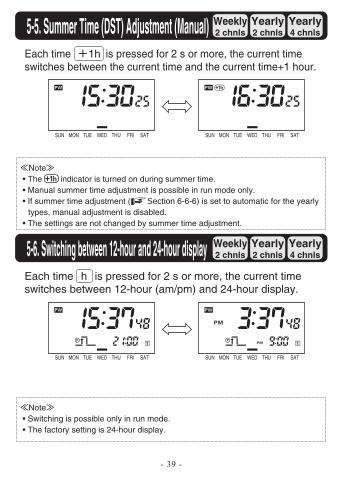
Each time is pressed for 2 s or more, the current time switches between the current time and the current time+1 hour.
Note • Switching is possible only in run mode. • The factory setting is 24-hour display.
Note • The indicator is turned on during summer time. • Manual summer time adjustment is possible in run mode only. • If summer time adjustment ( 6-6-6) is set to automatic for the yearly
types, manual adjustment is disabled. • The settings are not changed by summer time adjustment.
5-5. Summer Time (DST) Adjustment (Manual)
Weekly2 chnls
Yearly2 chnls
Yearly4 chnls
Each time is pressed for 2 s or more, the current time switches between 12-hour (am/pm) and 24-hour display.
5-6. Switching between 12-hour and 24-hour display
1h
h
TASIRFUHTDEWEUTNOMNUSTASIRFUHTDEWEUTNOMNUS
TASIRFUHTDEWEUTNOMNUSTASIRFUHTDEWEUTNOMNUS
- 40 -
Weekly2 chnls
Yearly2 chnls
Yearly4 chnls
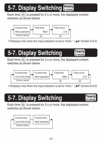
Each time is pressed for 2 s or more, the displayed content switches as shown below.
5-7. Display Switching
Current time
Next operation
(Factory setting)
Total time
hour
Displays only when the input selection is set to “totl”. ( 6-6-2)
Total count
cnt
Weekly2 chnls
Yearly2 chnls
Yearly4 chnls5-7. Display Switching
Current time
Current month and day
(Factory setting)
Current time
Next operation
Total time
hour
Total count
cnt
Weekly2 chnls
Yearly2 chnls
Yearly4 chnls5-7. Display Switching
Current time
Current month and day
(Factory setting)
Current time
Next operation
m
Each time is pressed for 2 s or more, the displayed content switches as shown below.
m
Each time is pressed for 2 s or more, the displayed content switches as shown below.
m
Displays only when the input selection is set to “totl”. ( 6-6-2)
- 41 -
Weekly2 chnls
Yearly2 chnls
Yearly4 chnls
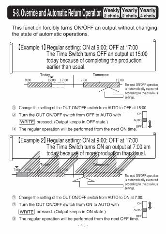
Example 1 Regular setting: ON at 9:00; OFF at 17:00The Time Switch turns OFF an output at 15:00 today because of completing the production earlier than usual.
Change the setting of the OUT ON/OFF switch from AUTO to OFF at 15:00.
Turn the OUT ON/OFF switch from OFF to AUTO with
pressed. (Output keeps in OFF state.)
The regular operation will be performed from the next ON time.
This function forcibly turns ON/OFF an output without changing the state of automatic operations.
9:00 15:00 17:00Today
9:00 17:00Tomorrow
The next ON/OFF operation is automatically executed according to the previous settings.
ON
AUTO
OFF
Example 2 Regular setting: ON at 9:00; OFF at 17:00The Time Switch turns ON an output at 7:00 am today because of more production than usual.
Change the setting of the OUT ON/OFF switch from AUTO to ON at 7:00.
Turn the OUT ON/OFF switch from ON to AUTO with
pressed. (Output keeps in ON state.)
The regular operation will be performed from the next OFF time.
9:00 00:7100:7Today
9:00 17:00Tomorrow
The next ON/OFF operation is automatically executed according to the previous settings.
ON
AUTO
OFF
5-8. Override and Automatic Return Operation
WRITE
WRITE
- 42 -
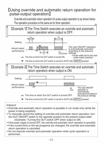
Example The Time Switch executes an override and automatic return operation when output is OFF.
Override and automatic return operation for pulse-output operation is as shown below.The operation procedure is the same as for timer operation.
Using override and automatic return operation for pulse-output operation
Setting
The time at which the OUT switch is turned ON.
The time at which the OUT switch is turned to AUTO with pressed.
Actual output performance
The next ON/OFF operation is automatically executed according to the previous settings.
Ta Tb
Tb
Example The Time Switch executes an override and automatic return operation when output is ON.
Setting
The time at which the OUT switch is turned OFF.
Actual output performance The next ON/OFF
operation is automatically executed according to the previous settings.
Note • Override and automatic return operation is possible in run mode only (while the
power is being supplied). • To manually cancel the setting of override and automatic return operation, turn
the OUT ON/OFF switch to the opposite position to the present output state.<Example> Turning the OUT switch OFF when output is ON.
• If the power supply is turned OFF, the override and automatic return operation is cancelled. • If the current time or the set programs are changed, the override and automatic
return operation is cancelled. • Do not execute override and automatic operation while cyclic operation is
performed.
WRITE
The time at which the OUT switch is turned to AUTO with pressed.WRITE
Pulse width set for the next pulse-output operation
6. Advanced Operations
- 43 -
6-1. Total Time/Count Display Weekly2 chnls
Yearly2 chnls
Yearly4 chnls
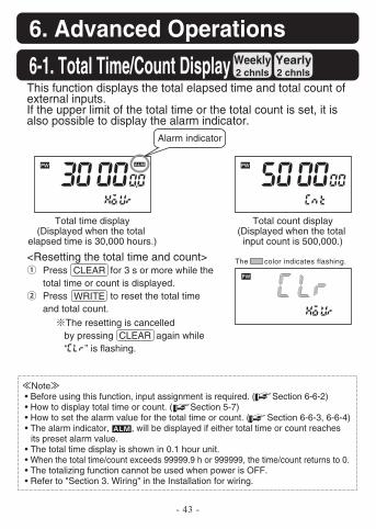
<Resetting the total time and count>Press for 3 s or more while the total time or count is displayed.Press to reset the total time and total count.
WRITE
This function displays the total elapsed time and total count of external inputs.If the upper limit of the total time or the total count is set, it is also possible to display the alarm indicator.
The resetting is cancelled by pressing again while “clr” is flashing.
Alarm indicator
Total time display(Displayed when the total
elapsed time is 30,000 hours.)
Note • Before using this function, input assignment is required. ( Section 6-6-2) • How to display total time or count. ( Section 5-7) • How to set the alarm value for the total time or count. ( Section 6-6-3, 6-6-4) • The alarm indicator, , will be displayed if either total time or count reaches
its preset alarm value. • The total time display is shown in 0.1 hour unit. • When the total time/count exceeds 99999.9 h or 999999, the time/count returns to 0. • The totalizing function cannot be used when power is OFF. • Refer to "Section 3. Wiring" in the Installation for wiring.
Total count display(Displayed when the total input count is 500,000.)
CLEAR
CLEAR
The color indicates flashing.
- 44 -
Weekly2 chnls
Yearly2 chnls
Yearly4 chnls
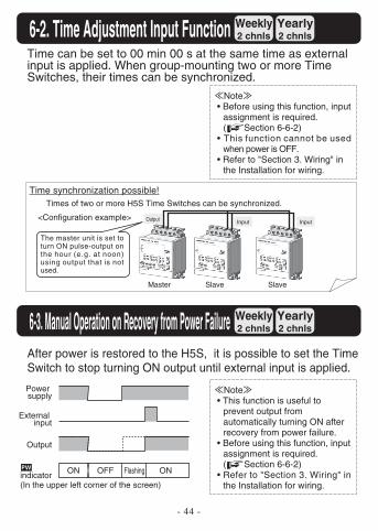
Time can be set to 00 min 00 s at the same time as external input is applied. When group-mounting two or more Time Switches, their times can be synchronized.
Note • Before using this function, input
assignment is required. ( Section 6-6-2)
• This function cannot be used when power is OFF.
• Refer to "Section 3. Wiring" in the Installation for wiring.
6-3. Manual Operation on Recovery from Power Failure Weekly2 chnls
Yearly2 chnls
Yearly4 chnls
After power is restored to the H5S, it is possible to set the Time Switch to stop turning ON output until external input is applied.
Note • This function is useful to
prevent output from automatically turning ON after recovery from power failure.
• Before using this function, input assignment is required. ( Section 6-6-2)
• Refer to "Section 3. Wiring" in the Installation for wiring.
Power supply
ON OFF Flashing ON
6-2. Time Adjustment Input Function
(In the upper left corner of the screen)
Times of two or more H5S Time Switches can be synchronized.
Time synchronization possible!
Master Slave Slave
<Configuration example>Input InputOutput
The master unit is set to turn ON pulse-output on the hour (e.g. at noon) using output that is not used.
indicator
External input
Output
- 45 -
Weekly2 chnls
Yearly2 chnls
Yearly4 chnls
Note • Before using this function, input assignment is required. ( Section 6-6-2) • Refer to "Section 3. Wiring" in the Installation for wiring.
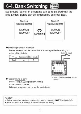
Programming a bankPress in program setting mode to switch banks.Different programs can be set for each bank.
Switching banks in run modeBanks are switched as shown in the following table depending on external input state.
Open-circuited
ABank
Short-circuited
B
Two groups (banks) of programs can be registered with the Time Switch. Banks can be switched by external input.
Bank A
Switching
Weekly programs
13:00 ON16:00 OFF
Bank BWeekly programs
8:00 ON10:00 OFF
TIME ADJ
6-4. Bank Switching
External input
- 46 -
Weekly2 chnls
Yearly2 chnls
Yearly4 chnls
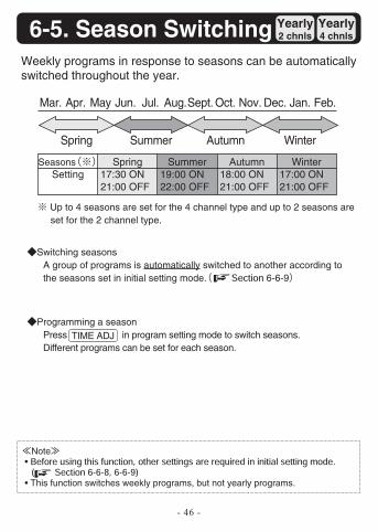
Programming a seasonPress in program setting mode to switch seasons.Different programs can be set for each season.
Weekly programs in response to seasons can be automatically switched throughout the year.
TIME ADJ
Switching seasonsA group of programs is automatically switched to another according to the seasons set in initial setting mode. 6-6-9
Up to 4 seasons are set for the 4 channel type and up to 2 seasons are set for the 2 channel type.
Note •
• This function switches weekly programs, but not yearly programs.
Mar. Apr. May Jun. Jul. Aug.Sept. Oct. Nov. Dec. Jan. Feb.
Spring Summer Autumn Winter
SeasonsSetting
Spring17:30 ON21:00 OFF
Summer19:00 ON22:00 OFF
Autumn18:00 ON21:00 OFF
Winter17:00 ON21:00 OFF
6-5. Season Switching
- 47 -
Weekly2 chnls
Yearly2 chnls
Yearly4 chnls
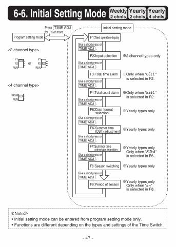
Note• Initial setting mode can be entered from program setting mode only.
• Functions are different depending on the types and settings of the Time Switch.
Program setting mode
Initial setting modePress for 3 s or more.
F1 Next operation display
Give a short press on .
F2 Input selection 2 channel types only
F3 Total time alarm Only when "totl" is selected in F2.
F4 Total count alarm Only when "totl" is selected in F2.
F5 Date format selection Yearly types only
F6 Summer time (DST) adjustment Yearly types only
F7 Summer time schedule selection Yearly types only
Only when "auto" is selected in F6.
F8 Season switching Yearly types only
F9 Period of seasonYearly types onlyOnly when "on" is selected in F8.
6-6. Initial Setting ModeTIME ADJ
TIME ADJ
Give a short press on .TIME ADJ
Give a short press on .TIME ADJ
Give a short press on .TIME ADJ
Give a short press on .TIME ADJ
Give a short press on .TIME ADJ
Give a short press on .TIME ADJ
Give a short press on .TIME ADJ
<2 channel type>
P1P2
RUN
P1P2
RUN
<4 channel type>
PRGMRUN
or
- 48 -
Weekly2 chnls
Yearly2 chnls
Yearly4 chnls
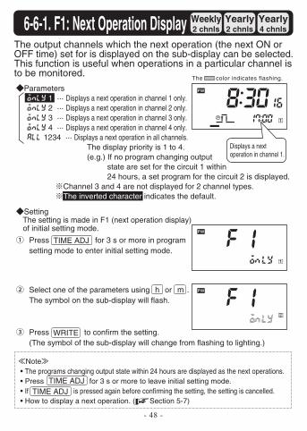
The output channels which the next operation (the next ON or OFF time) set for is displayed on the sub-display can be selected. This function is useful when operations in a particular channel is to be monitored.
SettingThe setting is made in F1 (next operation display) of initial setting mode.
Press for 3 s or more in program setting mode to enter initial setting mode.
Select one of the parameters using or . The symbol on the sub-display will flash.
Press to confirm the setting.(The symbol of the sub-display will change from flashing to lighting.)
Note• The programs changing output state within 24 hours are displayed as the next operations.• Press for 3 s or more to leave initial setting mode. • If is pressed again before confirming the setting, the setting is cancelled. • How to display a next operation. ( Section 5-7)
6-6-1. F1: Next Operation Display
Parametersonly 1 ··· Displays a next operation in channel 1 only.only 2 ··· Displays a next operation in channel 2 only.only 3 ··· Displays a next operation in channel 3 only.only 4 ··· Displays a next operation in channel 4 only.all 1234 ··· Displays a next operation in all channels.
The display priority is 1 to 4.(e.g.) If no program changing output
state are set for the circuit 1 within 24 hours, a set program for the circuit 2 is displayed.
Channel 3 and 4 are not displayed for 2 channel types.The inverted character indicates the default.
Displays a next operation in channel 1.
TIME ADJ
TIME ADJTIME ADJ
h m
The color indicates flashing.
WRITE
- 49 -
Weekly2 chnls
Yearly2 chnls
Yearly4 chnls
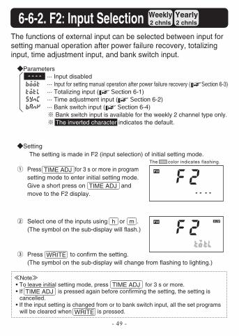
The functions of external input can be selected between input for setting manual operation after power failure recovery, totalizing input, time adjustment input, and bank switch input.
SettingThe setting is made in F2 (input selection) of initial setting mode.
Press for 3 s or more in program setting mode to enter initial setting mode. Give a short press on and move to the F2 display.
Select one of the inputs using or . (The symbol on the sub-display will flash.)
Press to confirm the setting. (The symbol on the sub-display will change from flashing to lighting.)
Note • To leave initial setting mode, press for 3 s or more. • If is pressed again before confirming the setting, the setting is
cancelled. • If the input setting is changed from or to bank switch input, all the set programs
will be cleared when is pressed.
6-6-2. F2 Input Selection
Parameters ---- ··· Input disabledboot ··· Input for setting manual operation after power failure recovery ( 6-3)totl ··· Totalizing input ( 6-1)sync ··· Time adjustment input ( 6-2)bank ··· Bank switch input ( 6-4)
Bank switch input is available for the weekly 2 channel type only. The inverted character indicates the default.
WRITE
WRITE
TIME ADJ
TIME ADJTIME ADJ
TIME ADJ
h m
The color indicates flashing.
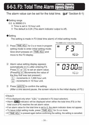
Note • F3 is displayed only when " totl" is selected in F2 (input selection). • Alarm ( indicator) will be displayed when either the total time (F3) or the
total count (F4) reaches the set alarm value. • If an alarm value for the total time is set to 0, the alarm indicator does not appear. • To leave initial setting mode, press for 3 s or more. • If is pressed again before confirming the setting, the setting is cancelled.
- 50 -
Weekly2 chnls
Yearly2 chnls
Yearly4 chnls
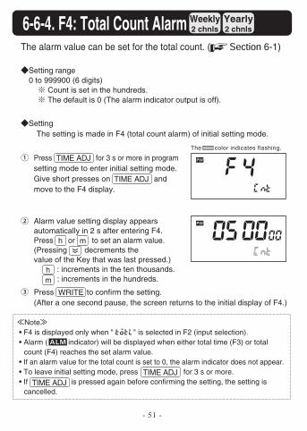
The alarm value can be set for the total time. ( 6-1)
SettingThe setting is made in F3 (total time alarm) of initial setting mode.
The color indicates flashing.
Press for 3 s or more in program setting mode to enter initial setting mode. Give short presses on and move to the F3 display.
Alarm value setting display appears automatically in 2 s after entering F3. Press or to set an alarm value. (Pressing decrements the value of the Key that was last pressed.)
: increments in 1,000 hour unit. : increments in 10 hour unit.
Press to confirm the setting.(After a one second pause, the screen returns to the initial display of F3.)
6-6-3. F3: Total Time Alarm
Setting range0.0 to 99990.0 h
Time is set in 10 hour unit. The default is 0.0h (The alarm indicator output is off).
m
h
h
m
TIME ADJ
TIME ADJTIME ADJ
TIME ADJ
WRITE
Note • F4 is displayed only when " totl" is selected in F2 (input selection). • Alarm ( indicator) will be displayed when either total time (F3) or total
count (F4) reaches the set alarm value. • If an alarm value for the total count is set to 0, the alarm indicator does not appear. • To leave initial setting mode, press for 3 s or more. • If is pressed again before confirming the setting, the setting is
cancelled.
- 51 -
Weekly2 chnls
Yearly2 chnls
Yearly4 chnls
The alarm value can be set for the total count. ( 6-1)
SettingThe setting is made in F4 (total count alarm) of initial setting mode.
Press for 3 s or more in program setting mode to enter initial setting mode. Give short presses on and move to the F4 display.
Alarm value setting display appears automatically in 2 s after entering F4. Press or to set an alarm value. (Pressing decrements the value of the Key that was last pressed.)
: increments in the ten thousands. : increments in the hundreds.
Press to confirm the setting.(After a one second pause, the screen returns to the initial display of F4.)
WRITE
6-6-4. F4: Total Count Alarm
Setting range0 to 999900 (6 digits)
Count is set in the hundreds. The default is 0 (The alarm indicator output is off).
m
m
h
h
The color indicates flashing.
TIME ADJ
TIME ADJ
TIME ADJTIME ADJ
- 52 -
Weekly2 chnls
Yearly2 chnls
Yearly4 chnls
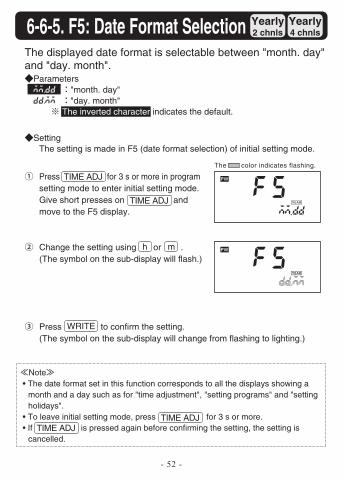
The displayed date format is selectable between "month. day" and "day. month".
SettingThe setting is made in F5 (date format selection) of initial setting mode.
Press for 3 s or more in program setting mode to enter initial setting mode. Give short presses on and move to the F5 display.
Change the setting using or . (The symbol on the sub-display will flash.)
Press to confirm the setting.(The symbol on the sub-display will change from flashing to lighting.)
Note • The date format set in this function corresponds to all the displays showing a
month and a day such as for "time adjustment", "setting programs" and "setting holidays".
• To leave initial setting mode, press for 3 s or more. • If is pressed again before confirming the setting, the setting is
cancelled.
6-6-5. F5: Date Format Selection
Parametersmm.dd "month. day"dd.mm "day. month"
The inverted character indicates the default.
h m
The color indicates flashing.
TIME ADJ
TIME ADJTIME ADJ
TIME ADJ
WRITE
- 53 -
Weekly2 chnls
Yearly2 chnls
Yearly4 chnls
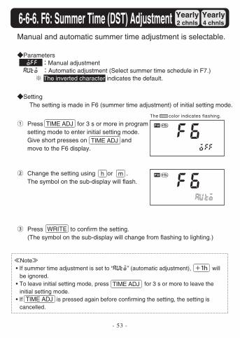
Manual and automatic summer time adjustment is selectable.
SettingThe setting is made in F6 (summer time adjustment) of initial setting mode.
Press for 3 s or more in program setting mode to enter initial setting mode. Give short presses on and move to the F6 display.
Change the setting using or . The symbol on the sub-display will flash.
Press to confirm the setting. (The symbol on the sub-display will change from flashing to lighting.)
Note• If summer time adjustment is set to “auto” (automatic adjustment), will
be ignored. • To leave initial setting mode, press for 3 s or more to leave the
initial setting mode. • If is pressed again before confirming the setting, the setting is
cancelled.
6-6-6. F6: Summer Time (DST) Adjustment
Parameters off Manual adjustmentauto Automatic adjustment (Select summer time schedule in F7.)
The inverted character indicates the default.
h m
The color indicates flashing.
TIME ADJ
TIME ADJ
TIME ADJ
TIME ADJ
WRITE
- 54 -
Weekly2 chnls
Yearly2 chnls
Yearly4 chnls
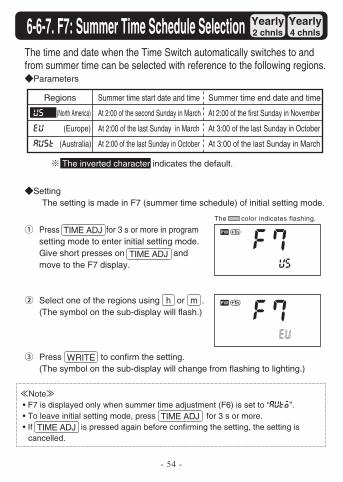
The time and date when the Time Switch automatically switches to and from summer time can be selected with reference to the following regions.
SettingThe setting is made in F7 (summer time schedule) of initial setting mode.
Press for 3 s or more in program setting mode to enter initial setting mode. Give short presses on and move to the F7 display.
Select one of the regions using or . (The symbol on the sub-display will flash.)
Press to confirm the setting. (The symbol on the sub-display will change from flashing to lighting.)
Note• F7 is displayed only when summer time adjustment (F6) is set to “auto”.
• To leave initial setting mode, press for 3 s or more. • If is pressed again before confirming the setting, the setting is
cancelled.
6-6-7. F7: Summer Time Schedule Selection
Parameters
The inverted character indicates the default.
Regions
us (North America)
eu (Europe)
aust (Australia)
Summer time start date and time
At 2:00 of the second Sunday in March
At 2:00 of the last Sunday in March
At 2:00 of the last Sunday in October
Summer time end date and time
At 2:00 of the first Sunday in November
At 3:00 of the last Sunday in October
At 3:00 of the last Sunday in March
h m
The color indicates flashing.
TIME ADJ
TIME ADJ
TIME ADJTIME ADJ
WRITE
- 55 -
Weekly2 chnls
Yearly2 chnls
Yearly4 chnls
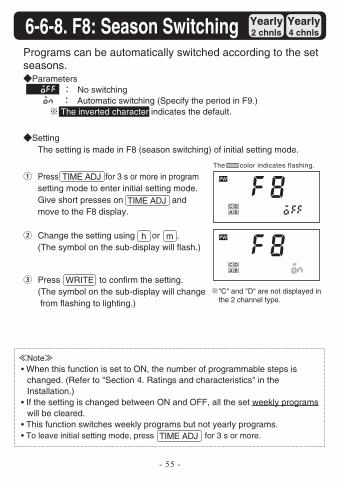
"C" and "D" are not displayed in the 2 channel type.
Programs can be automatically switched according to the set seasons.
SettingThe setting is made in F8 (season switching) of initial setting mode.
Press for 3 s or more in program setting mode to enter initial setting mode. Give short presses on and move to the F8 display.
Change the setting using or . (The symbol on the sub-display will flash.)
Press to confirm the setting. (The symbol on the sub-display will change from flashing to lighting.)
6-6-8. F8: Season Switching
Parametersoff No switching on Automatic switching (Specify the period in F9.)
The inverted character indicates the default.
Note • When this function is set to ON, the number of programmable steps is
changed. (Refer to "Section 4. Ratings and characteristics" in the Installation.)
• If the setting is changed between ON and OFF, all the set weekly programs will be cleared.
• This function switches weekly programs but not yearly programs. • To leave initial setting mode, press for 3 s or more.
The color indicates flashing.
TIME ADJ
TIME ADJ
TIME ADJ
h m
WRITE
- 56 -
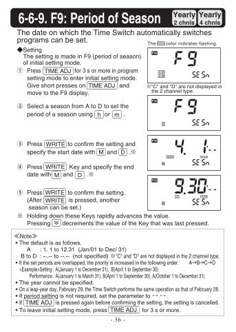
Press to confirm the setting.(After is pressed, another season can be set.)Holding down these Keys rapidly advances the value.Pressing decrements the value of the Key that was last pressed.
Select a season from A to D to set the period of a season using or .
Note• The default is as follows.
A : 1. 1 to 12.31 (Jan/01 to Dec/ 31)B to D : --.-- to --.-- (not specified) "C" and "D" are not displayed in the 2 channel type.
• If the set periods are overlapped, the priority is increased in the following order. A B C D<Example>Setting : A(January 1 to December 31), B(April 1 to September 30)
Performance : A(January 1 to March 31), B(April 1 to September 30), A(October 1 to December 31) • The year cannot be specified. • On a leap-year day, February 29, the Time Switch performs the same operation as that of February 28. • If period setting is not required, set the parameter to --.--. • If is pressed again before confirming the setting, the setting is cancelled. • To leave initial setting mode, press for 3 s or more.
Press Key and specify the end date with and .
Press to confirm the setting and specify the start date with and .
Press for 3 s or more in program setting mode to enter initial setting mode. Give short presses on and move to the F9 display.
"C" and "D" are not displayed in the 2 channel type.
Weekly2 chnls
Yearly2 chnls
Yearly4 chnls
The date on which the Time Switch automatically switches programs can be set.
6-6-9. F9: Period of Season
SettingThe setting is made in F9 (period of season) of initial setting mode.
M
M
D
D
The color indicates flashing.
TIME ADJ
TIME ADJ
TIME ADJTIME ADJ
h m
WRITE
WRITE
WRITEWRITE
- 57 -
Weekly2 chnls
Yearly2 chnls
Yearly4 chnls
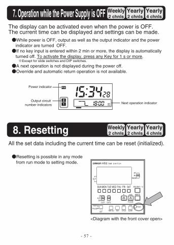
The display can be activated even when the power is OFF. The current time can be displayed and settings can be made.
7. Operation while the Power Supply is OFF
While power is OFF, output as well as the output indicator and the power indicator are turned OFF.If no key input is entered within 2 min or more, the display is automatically turned off. To activate the display, press any Key for 1 s or more.
Except for slide switches and DIP switches.
A next operation is not displayed during the power off.Override and automatic return operation is not available.
Weekly2 chnls
Yearly2 chnls
Yearly4 chnls
All the set data including the current time can be reset (initialized).
8. Resetting
Resetting is possible in any mode from run mode to setting mode.
<Diagram with the front cover open>
Power indicator
Output circuit number indicators Next operation indicator
RESET
TEST
COPY
CYCLE CLEARTIME ADJOUT
PULSE
TIMER
HOLIDAY /
ONAUTO
OFF
OUT
SATFRITHUWEDTUEMONSUN
P2P1
RUN
PULSE
h min WRITE
OUT1 OUT2
- 58 -
Weekly2 chnls
Yearly2 chnls
Yearly4 chnls9. Time Accuracy
Weekly2 chnls
Yearly2 chnls
Yearly4 chnls
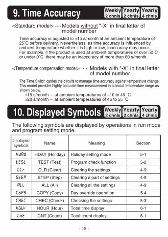
The following symbols are displayed by operations in run mode and program setting mode.
10. Displayed Symbols
<Standard model> ···· Models without "-X" in final letter of model number
Time accuracy is adjusted to ±15 s/month at an ambient temperature of 25˚C before delivery. Nevertheless, as time accuracy is influenced by ambient temperature whether it is high or low, inaccuracy may occur. For example, if the product is used at ambient temperatures of over 50˚C or under 0˚C, there may be an inaccuracy of more than 60 s/month.
<Temperature compensation model> ···· Models with "-X" in final letter of model number .
The Time Switch carries the circuits to manage time accuracy against temperature change. This model provides highly accurate time measurement in a broad temperature range as shown below.
±15 s/month ··· at ambient temperatures of –10 to 45 ˚C±20 s/month ··· at ambient temperatures of 45 to 55 ˚C
Displayed symbols
hday
test
clr
step
all
copy
chec
hour
cnt
Name
HDAY (Holiday)
TEST (Test)
CLR (Clear)
STEP (Step)
ALL (All)
COPY (Copy)
CHEC (Check)
HOUR (Hour)
CNT (Count)
Section
5-1
5-2
4-9
4-9
4-9
5-4
5-3
6-1
6-1
Meaning
Holiday setting mode
Program check function
Clearing the settings
Clearing a part of settings
Clearing all the settings
Day override operation
Checking the settings
Total time display
Total count display
- 59 -
Weekly2 chnls
Yearly2 chnls
Yearly4 chnls11. Troubleshooting
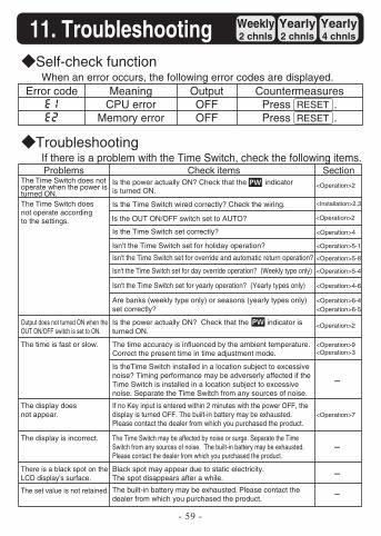
Self-check functionWhen an error occurs, the following error codes are displayed.
Error codee1
e2
MeaningCPU error
Memory error
OutputOFFOFF
CountermeasuresPress .Press .
TroubleshootingIf there is a problem with the Time Switch, check the following items.Problems
Output does not turned ON when theOUT ON/OFF switch is set to ON.
The time is fast or slow.
The display does not appear.
The display is incorrect.
There is a black spot on the LCD display's surface.
Check itemsIs the power actually ON? Check that the indicator is turned ON.
Is the Time Switch wired correctly? Check the wiring.
Is the OUT ON/OFF switch set to AUTO?
Is the Time Switch set correctly?
Isn't the Time Switch set for holiday operation?
Isn't the Time Switch set for override and automatic return operation?
Isn't the Time Switch set for day override operation? (Weekly type only)
Isn't the Time Switch set for yearly operation? (Yearly types only)
Are banks (weekly type only) or seasons (yearly types only) set correctly?
Is the power actually ON? Check that the indicator is turned ON.
The time accuracy is influenced by the ambient temperature. Correct the present time in time adjustment mode.
Is theTime Switch installed in a location subject to excessive noise? Timing performance may be adverserly affected if the Time Switch is installed in a location subject to excessive noise. Separate the Time Switch from any sources of noise.
If no Key input is entered within 2 minutes with the power OFF, the display is turned OFF. The built-in battery may be exhausted. Please contact the dealer from which you purchased the product.
The Time Switch may be affected by noise or surge. Separate the Time Switch from any sources of noise. The built-in battery may be exhausted. Please contact the dealer from which you purchased the product.
Black spot may appear due to static electricity. The spot disappears after a while.
Section
<Operation>2
<Installation>2,3
<Operation>2
<Operation>4
<Operation>5-1
<Operation>5-8
<Operation>5-4
<Operation>4-6
<Operation>6-4<Operation>6-5
<Operation>2
<Operation>9<Operation>3
<Operation>7
RESETRESET
The Time Switch does not operate when the power is turned ON.The Time Switch doesnot operate according to the settings.
The set value is not retained. The built-in battery may be exhausted. Please contact the dealer from which you purchased the product.
Installation
- 60 -
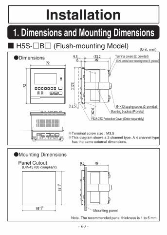
H5S- B (Flush-mounting Model)(Unit: mm)
Mounting panel
Mounting brackets (Provided)
Terminal covers (2; provided)
M4 12 tapping screws (2; provided)
Y92A-72C Protective Cover (Order separately)
68+0
.8 0
68+0.80
Dimensions
Terminal screw size : M3.5This diagram shows a 2 channel type. A 4 channel type has the same external dimensions.
Mounting Dimensions
Panel Cutout
Note The recommended panel thickness is 1 to 5 mm.
(DIN43700 compliant)
1. Dimensions and Mounting Dimensions
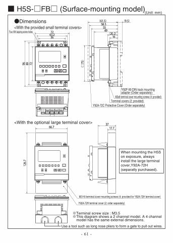
H5S- FB (Surface-mounting model)(Unit: mm)
Dimensions<With the provided small terminal covers>
<With the optional large terminal cover>
Terminal screw size : M3.5This diagram shows a 2 channel model. A 4 channel model has the same external dimensions.
Use a tool such as long nose pliers to form a gate to pull out wires.
Y92A-72C Protective Cover (Order separately)
Y92F-90 DIN track mounting adapter (Order separately)
M3x8 terminal cover mounting screws (4; provided)Terminal covers (2; provided)
Four M4 tapping screw holes
M3 8 terminal cover mounting screws (4; provided for Y92A-72H terminal cover)
Y92A-72H terminal cover (2; order separately)
- 61 -
When mounting the H5S on exposure, always install the large terminal cover,Y92A-72H (separatly purchased).
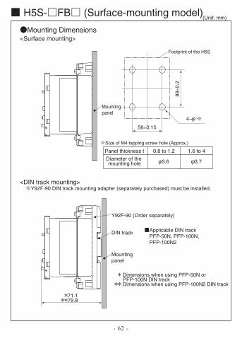
H5S- FB (Surface-mounting model)(Unit: mm)
Mounting Dimensions<Surface mounting>
<DIN track mounting>
- 62 -
89±0
.2
56±0.15
4–
Y92F-90 (Order separately)
DIN track
Mounting panel
DIN track mounting adapter (separately purchased) must be installed.
Applicable DIN trackPFP-50N, PFP-100N,PFP-100N2
Panel thickness t
Diameter of the mounting hole
0.8 to 1.2
3.6
1.6 to 4
3.7
Mounting panel
Footprint of the H5S
71.179.8
Dimensions when using PFP-50N or PFP-100N DIN track
Dimensions when using PFP-100N2 DIN track
Size of M4 tapping screw hole (Approx.)
- 63 -
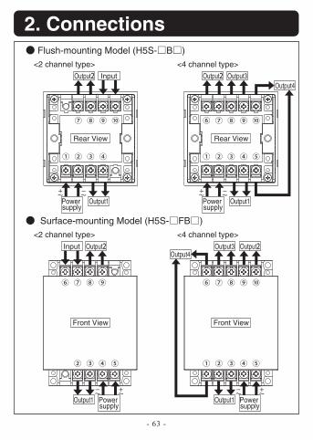
2. Connections Flush-mounting Model (H5S- B )
>epyt lennahc 4<>epyt lennahc 2<Output Output Output3
Output4
Output1Power supply
Rear View Rear View
Front View Front View
Input
Output1Power supply
Surface-mounting Model (H5S- FB )>epyt lennahc 4<>epyt lennahc 2<
Output OutputOutput3Output4
Input
Output1 Power supply
Output1 Power supply
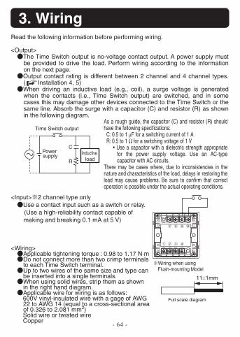
- 64 -
3. WiringRead the following information before performing wiring.
<Output>The Time Switch output is no-voltage contact output. A power supply must be provided to drive the load. Perform wiring according to the information on the next page.Output contact rating is different between 2 channel and 4 channel types. ( Installation 4, 5)When driving an inductive load (e.g., coil), a surge voltage is generated when the contacts (i.e., Time Switch output) are switched, and in some cases this may damage other devices connected to the Time Switch or the same line. Absorb the surge with a capacitor (C) and resistor (R) as shown in the following diagram.
<Input> 2 channel type onlyUse a contact input such as a switch or relay.(Use a high-reliability contact capable of making and breaking 0.1 mA at 5 V)
As a rough guide, the capacitor (C) and resistor (R) should have the following specifications: C: 0.5 to 1 μF for a switching current of 1 A R: 0.5 to 1 Ω for a switching voltage of 1 V
• Use a capacitor with a dielectric strength appropriate for the power supply voltage. Use an AC-type capacitor with AC circuits.
There may be cases where, due to inconsistencies in the nature and characteristics of the load, delays in restoring the load may cause problems. Be sure to confirm that correct operation is possible under the actual operating conditions.
<Wiring>Applicable tightening torque : 0.98 to 1.17 N·mDo not connect more than two crimp terminals to each Time Switch terminal.Up to two wires of the same size and type can be inserted into a single terminals.When using solid wires, strip them as shown in the right hand diagram.Applicable wire for wiring is as follows:600V vinyl-insulated wire with a gage of AWG 22 to AWG 14 (equal to a cross-sectional area of 0.326 to 2.081 mm2)Solid wire or twisted wire
Copper
C
R
Inductive load
Power supply
Time Switch output
Wiring when using Flush-mounting Model
11±1mm
Full scale diagram
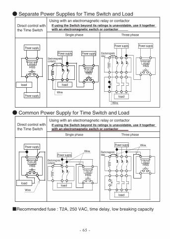
Separate Power Supplies for Time Switch and Load
Common Power Supply for Time Switch and Load
Direct control with the Time Switch
Using with an electromagnetic relay or contactorIf using the Switch beyond its ratings is unavoidable, use it together with an electromagnetic switch or contactor
esahp eerhTesahp elgniS
esahp eerhTesahp elgniS
Recommended fuse : T2A, 250 VAC, time delay, low breaking capacity
Power supply
internal circuit
internal circuit
internal circuit
internal circuit
internal circuit
internal circuit
load load
Power supply Power supply
Power supplyPower supply
load
H5S
Power supply
loadload
Power supplyPower supply
load
H5S
H5S
H5S
H5S
Power supply
Electromagnetic contactor
Electromagnetic relay
Electromagnetic contactor
Electromagnetic relay
Wire
H5S
Wire
Wire
Wire
Wire
Using with an electromagnetic relay or contactorIf using the Switch beyond its ratings is unavoidable, use it together with an electromagnetic switch or contactor
Direct control with the Time Switch
- 65 -
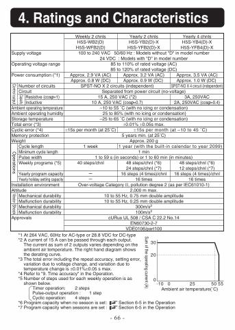
- 66 -
4. Ratings and Characteristics
Supply voltage
Operating voltage range
Power consumption (*1)
Number of circuitsCircuit
Resistive (cos =1)Inductive
Ambient operating temperatureAmbient operating humidityStorage temperatureTotal error (*3)Cyclic error (*4)Memory protectionWeight
Cycle lengthMinimum cycle lengthPulse widthWeekly programs (*5)
Yearly program capacityYearly holiday setting capacity
Installation environmentAltitude
Mechanical durabilityMalfunction durabilityMechanical durabilityMalfunction durability
Approvals
Weekly 2 chnlsH5S-WB2(D)
H5S-WFB2(D)
Approx. 2.9 VA (AC)Approx. 0.8 W (DC)
±15s per month (at 25˚C)
1 week
40 steps/chnl
SPST-NO X 2 circuits (independent)
15 A, 250 VAC (*2)10 A, 250 VAC (cos =0.7)
±15s per month (at –10 to 45 ˚C)
1 year (with the built-in calendar to year 2099)
Yearly 4 chnlsH5S-YB4(D)-X
H5S-YFB4(D)-X
Approx. 3.5 VA (AC)Approx. 1.0 W (DC)
SPST-NO X 4 circuit (independent)
3A, 250VAC2A, 250VAC (cos =0.4)
48 steps/chnl (*6)12 steps/chnl (*7)
16 steps (4 times)/chnl16 times
Yearly 2 chnlsH5S-YB2(D)-X
H5S-YFB2(D)-X100 to 240 VAC 50/60 Hz : Models without "D" in model number
24 VDC : Models with "D" in model number85 to 110% of rated voltage (AC)85 to 120% of rated voltage (DC)
Approx. 3.2 VA (AC)Approx. 0.9 W (DC)
Separated from power circuit (no-voltage)
–10 to 55 ˚C (with no icing or condensation) 25 to 85% (with no icing or condensation)
–25 to 65 ˚C (with no icing or condensation)±0.01% ±0.05s max.
5 years min. (at 25˚C)Approx. 200 g
1 min1 to 59 s (in seconds) or 1 to 60 min (in minutes)
48 steps/chnl (*6)24 steps/chnl (*7)
16 steps (4 times)/chnl16 times
Over-voltage Category II, pollution degree 2 (as per IEC61010-1)2,000 m max.
10 to 55 Hz, 0.75 mm double amplitude10 to 55 Hz, 0.25 mm double amplitude
300m/s2
100m/s2
cURus UL 508 / CSA C 22.2 No.14EN60730-2-7
VDE0106/part100
Control output
Capacity
Operations
VibrationShock
*1 At 264 VAC, 60Hz for AC-type or 28.8 VDC for DC-type*2 A current of 15 A can be passed through each output.
The current as sum of 2 outputs varies depending on the ambient air temperature. The right hand diagram shows the derating curve.
*3 The total error including the repeat accuracy, setting error, variation due to voltage change, and variation due to temperature change is ±0.01%±0.05 s max.
*4 Refer to "9. Time accuracy" in the Operation.*5 Number of steps used for each weekly operation is as
shown below.Timer operation: 2 stepsPulse-output operation : 1 stepCyclic operation: 4 steps
*6 Program capacity when no season is set : Section 6-5 in the Operation*7 Program capacity when seasons are set : Section 6-5 in the Operation
0-10 0 25 50 55
20
30
Ambient air temperature(˚C)
Sum of the operating current (A)
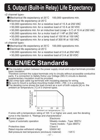
- 67 -
6. EN/IEC Standards
5. Output (Built-in Relay) Life Expectancy
The insulation system between the power supply circuit and output terminals provides basic insulation.Therefore connect the output terminals only to circuits without accessible conductive parts. If a connection to Safety Extra Low-Voltage (SELV) circuits is desired, supplementary insulation must be provided.Use crimp type cable lug terminals with insulating sleeves for wiring.Be sure to mount a surface-mounting model (H5S- FB ) in a enclosure.The derating curve shows the load current as a sum of both outputs [A] vs. the ambient air temperature [˚C] of 2 channel types.
If wires with a temperature rating of 105 ˚C or higher are used, see the derating curve in the Section 4, "Ratings and characteristics".Control system ElectronicTypes of automatic operation Weekly models - Type 1BSTU
Yearly models - Type 2BSTUProtective class Class 0Rated impulse withstand voltage 2500V ACBall-pressure test temparature (enclosure material) 125˚C
0-10 0 4025 55
20
30
Ambient air temperature (˚C)
Load current as sum
of 2 outputs (A)
<2 channel type>Mechanical life expectancy at 20˚C 100,000 operations min.Electrical life expectancy at 20˚C• 50,000 operations min. for a resistive load of 15 A at 250 VAC• 50,000 operations min. for a resistive load of 10 A at 30 VDC• 50,000 operations min. for an inductive load (cos = 0.7) of 10 A at 250 VAC• 50,000 operations min. for a motor load of 1 HP at 250 VAC• 50,000 operations min. for a lamp load of 100 W at 100 VAC• 10,000 operations min. for a lamp load of 300 W at 100 VAC
<4 channel type>Mechanical life expectancy at 20˚C 100,000 operations min.Electrical life expectancy at 20˚C• 50,000 operations min. for a resistive load of 3 A at 250 VAC• 50,000 operations min. for a resistive load of 3 A at 30 VDC
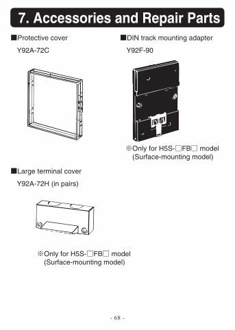
- 68 -
7. Accessories and Repair PartsProtective cover
Y92A-72C
Large terminal cover
Y92A-72H (in pairs)
DIN track mounting adapter
Only for H5S- FB model (Surface-mounting model)
Only for H5S- FB model (Surface-mounting model)
Y92F-90
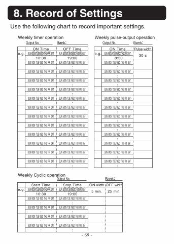
- 69 -
8. Record of SettingsUse the following chart to record important settings.
Weekly timer operationOutput No. Bank
ON TimeSUN MON TUE WED THU FRI SAT
10:30SUN MON TUE WED THU FRI SAT
:SUN MON TUE WED THU FRI SAT
:SUN MON TUE WED THU FRI SAT
:SUN MON TUE WED THU FRI SAT
:SUN MON TUE WED THU FRI SAT
:SUN MON TUE WED THU FRI SAT
:SUN MON TUE WED THU FRI SAT
:SUN MON TUE WED THU FRI SAT
:SUN MON TUE WED THU FRI SAT
:SUN MON TUE WED THU FRI SAT
:SUN MON TUE WED THU FRI SAT
:SUN MON TUE WED THU FRI SAT
:
e.g.OFF Time
SUN MON TUE WED THU FRI SAT19:00
SUN MON TUE WED THU FRI SAT:
SUN MON TUE WED THU FRI SAT:
SUN MON TUE WED THU FRI SAT:
SUN MON TUE WED THU FRI SAT:
SUN MON TUE WED THU FRI SAT:
SUN MON TUE WED THU FRI SAT:
SUN MON TUE WED THU FRI SAT:
SUN MON TUE WED THU FRI SAT:
SUN MON TUE WED THU FRI SAT:
SUN MON TUE WED THU FRI SAT:
SUN MON TUE WED THU FRI SAT:
SUN MON TUE WED THU FRI SAT:
Weekly Cyclic operationOutput No. Bank
Start TimeSUN MON TUE WED THU FRI SAT
10:30SUN MON TUE WED THU FRI SAT
:SUN MON TUE WED THU FRI SAT
:SUN MON TUE WED THU FRI SAT
:SUN MON TUE WED THU FRI SAT
:
e.g.Stop Time
SUN MON TUE WED THU FRI SAT19:00
SUN MON TUE WED THU FRI SAT:
SUN MON TUE WED THU FRI SAT:
SUN MON TUE WED THU FRI SAT:
SUN MON TUE WED THU FRI SAT:
ON width
5 min.
OFF width
25 min.
Weekly pulse-output operationOutput No. Bank
ON TimeSUN MON TUE WED THU FRI SAT
8:30SUN MON TUE WED THU FRI SAT
:SUN MON TUE WED THU FRI SAT
:SUN MON TUE WED THU FRI SAT
:SUN MON TUE WED THU FRI SAT
:SUN MON TUE WED THU FRI SAT
:SUN MON TUE WED THU FRI SAT
:SUN MON TUE WED THU FRI SAT
:SUN MON TUE WED THU FRI SAT
:SUN MON TUE WED THU FRI SAT
:SUN MON TUE WED THU FRI SAT
:SUN MON TUE WED THU FRI SAT
:SUN MON TUE WED THU FRI SAT
:
e.g.Pulse width
30 s
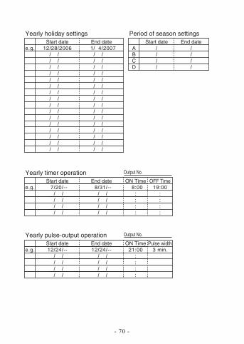
- 70 -
Yearly holiday settingsStart date
12 28 2006e.g.End date1 4 2007
Period of season settingsStart date
ABCD
End date
Yearly timer operation Output No.
Start date7 20 --e.g.
End date8 31 --
ON Time 8:00
::::
OFF Time19:00
::::
Yearly pulse-output operation Output No.
Start date12 24 --e.g.
End date12 24 --
ON Time21:00
::::
Pulse width3 min.
OMRON CANADA, INC. • HEAD OFFICEToronto, ON, Canada • 416.286.6465 • 866.986.6766 • www.omron247.com
OMRON ELECTRONICS DE MEXICO • HEAD OFFICEMéxico DF • 52.55.59.01.43.00 • 01-800-226-6766 • [email protected]
OMRON ELECTRONICS DE MEXICO • SALES OFFICEApodaca, N.L. • 52.81.11.56.99.20 • 01-800-226-6766 • [email protected]
OMRON ELETRÔNICA DO BRASIL LTDA • HEAD OFFICESão Paulo, SP, Brasil • 55.11.2101.6300 • www.omron.com.br
OMRON ARGENTINA • SALES OFFICECono Sur • 54.11.4783.5300
OMRON CHILE • SALES OFFICESantiago • 56.9.9917.3920
OTHER OMRON LATIN AMERICA SALES54.11.4783.5300
Authorized Distributor:
INST-9966572-0B 03/11 Note: Specifications are subject to change. © 2015 Omron Electronics LLC Printed in U.S.A.
Printed on recycled paper.
Automation Control Systems• Machine Automation Controllers (MAC) • Programmable Controllers (PLC) • Operator interfaces (HMI) • Distributed I/O • Software
Drives & Motion Controls • Servo & AC Drives • Motion Controllers & Encoders
Temperature & Process Controllers • Single and Multi-loop Controllers
Sensors & Vision• Proximity Sensors • Photoelectric Sensors • Fiber-Optic Sensors• Amplified Photomicrosensors • Measurement Sensors• Ultrasonic Sensors • Vision Sensors
Industrial Components • RFID/Code Readers • Relays • Pushbuttons & Indicators• Limit and Basic Switches • Timers • Counters • Metering Devices • Power Supplies
Safety • Laser Scanners • Safety Mats • Edges and Bumpers • Programmable Safety Controllers • Light Curtains • Safety Relays • Safety Interlock Switches
OMRON AUTOMATION AND SAFETY • THE AMERICAS HEADQUARTERS • Chicago, IL USA • 847.843.7900 • 800.556.6766 • www.omron247.com
OMRON EUROPE B.V. • Wegalaan 67-69, NL-2132 JD, Hoofddorp, The Netherlands. • +31 (0) 23 568 13 00 • www.industrial.omron.eu