Embed Size (px)
Citation preview
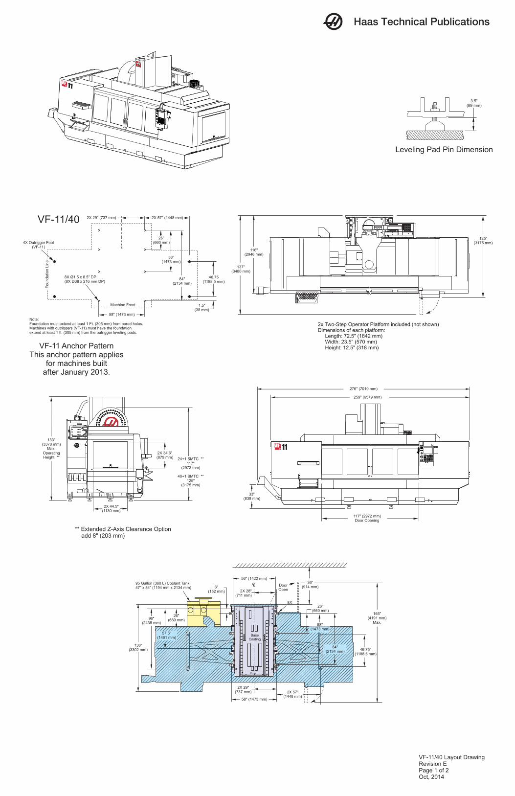
Leveling Pad Pin Dimension
3.5"(89 mm)
Haas Technical Publications
24+1 SMTC **117"
(2972 mm)
40+1 SMTC **125"
(3175 mm)
133"(3378 mm)
Max.OperatingHeight **
2X 34.6"(879 mm)
2X 44.5"(1130 mm)
259" (6579 mm)
276" (7010 mm)
117" (2972 mm)Door Opening
33"(838 mm)
VF-11 Anchor PatternThis anchor pattern applies
for machines builtafter January 2013.
Note:Foundation must extend at least 1 Ft. (305 mm) from bored holes.Machines with outriggers (VF-11) must have the foundationextend at least 1 ft. (305 mm) from the outrigger leveling pads.
VF-11/40
58" (1473 mm)
58"(1473 mm)
84"(2134 mm)
26"(660 mm)
Machine Front
2X 57" (1448 mm)
46.75(1188.5 mm)
1.5"(38 mm)
4X Outrigger Foot(VF-11)
Foundatio
n L
ine
8X Ø1.5 x 8.5" DP(8X Ø38 x 216 mm DP)
2X 29" (737 mm)
CL
DoorOpen
2X 57"(1448 mm)
46.75"(1188.5 mm)
36”(914 mm)
CL
96"(2438 mm)
57.5"(1461 mm)
26"(660 mm)
56" (1422 mm)
130"(3302 mm)
2X 28"(711 mm)
165"(4191 mm)
Max.
95 Gallon (360 L) Coolant Tank 47" x 84" (1194 mm x 2134 mm)
58" (1473 mm)
26"(660 mm)
84"(2134 mm)
8X
Front
BaseCasting
2X 29(737 mm)
"
6"(152 mm)
** Extended Z-Axis Clearance Option add 8" (203 mm)
137"(3480 mm)
125"(3175 mm)
116"(2946 mm)
2x Two-Step Operator Platform included (not shown)Dimensions of each platform: Length: 72.5" (1842 mm) Width: 23.5" (570 mm) Height: 12.5" (318 mm)
VF-11/40 Layout DrawingRevision EPage 1 of 2Oct, 2014
58"(1473 mm)
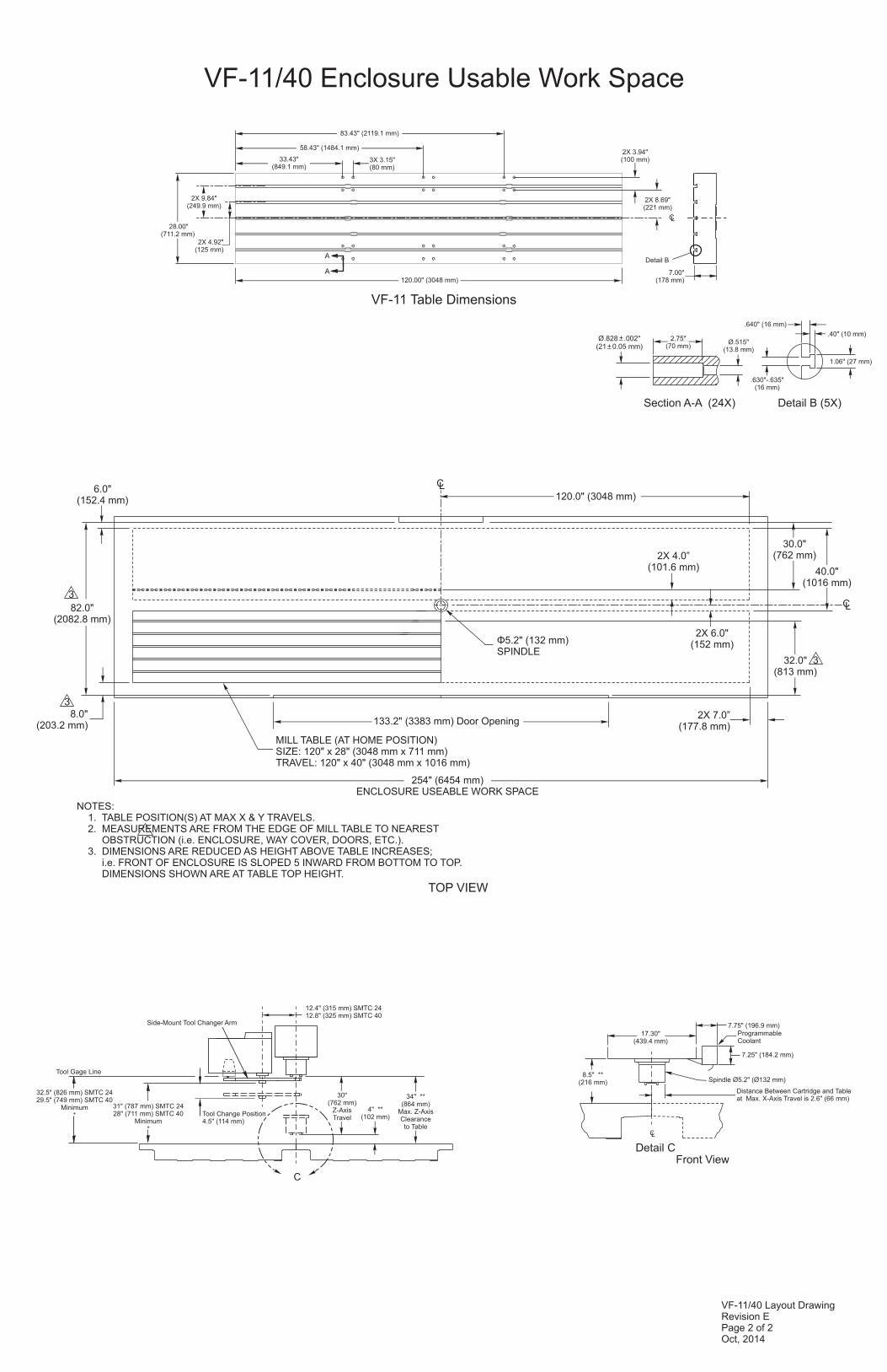
VF-11/40 Layout DrawingRevision EPage 2 of 2Oct, 2014
.640" (16 mm)
.40" (10 mm)
.630"-.635" (16 mm)
Detail B (5X)
1.06" (27 mm)
Section A-A (24X)
2.75" (70 mm)
Ø.515"(13.8 mm)
Ø.828 .002"(21 0.05 mm)
+_
+_
VF-11/40 Enclosure Usable Work Space
VF-11 Table Dimensions
7.00"(178 mm)
Detail B
2X 4.92"(125 mm)
2X 3.94"(100 mm)
2X 8.69"(221 mm)
33.43"(849.1 mm)
3X 3.15"(80 mm)
58.43" (1484.1 mm)
120.00" (3048 mm)
CL
2X 9.84"(249.9 mm)
28.00"(711.2 mm)
A
A
83.43" (2119.1 mm)
8.5" ** (216 mm)
Detail C
Distance Between Cartridge and Table at Max. X-Axis Travel is 2.6" (66 mm)
Spindle Ø5.2" (Ø132 mm)
17.30"(439.4 mm)
7.75" (196.9 mm)Programmable Coolant
7.25" (184.2 mm)
Front View
CL
4" **(102 mm)
30"(762 mm)
Z-AxisTravel
34" **(864 mm)
Max. Z-AxisClearanceto Table
C
Tool Change Position4.5" (114 mm)
Tool Gage Line
32.5" (826 mm) SMTC 2429.5" (749 mm) SMTC 40
Minimum*
31" (787 mm) SMTC 2428" (711 mm) SMTC 40
Minimum*
Side-Mount Tool Changer Arm
12.4" (315 mm) SMTC 2412.8" (325 mm) SMTC 40
NOTES: 1. TABLE POSITION(S) AT MAX X & Y TRAVELS. 2. MEASUREMENTS ARE FROM THE EDGE OF MILL TABLE TO NEAREST OBSTRUCTION (i.e. ENCLOSURE, WAY COVER, DOORS, ETC.). 3. DIMENSIONS ARE REDUCED AS HEIGHT ABOVE TABLE INCREASES; i.e. FRONT OF ENCLOSURE IS SLOPED 5 INWARD FROM BOTTOM TO TOP. DIMENSIONS SHOWN ARE AT TABLE TOP HEIGHT.
8.0" (203.2 mm)
3
133.2" (3383 mm) Door Opening
254" ENCLOSURE USEABLE WORK SPACE
(6454 mm)
MILL TABLE (AT HOME POSITION)SIZE: 120" x 28" (3048 mm x 711 mm)TRAVEL: 120" x 40" (3048 mm x 1016 mm)
Φ5.2" SPINDLE
(132 mm)
82.0"(2082.8 mm)
3
6.0"(152.4 mm) 120.0" (3048 mm)
332.0"(813 mm)
2X 6.0"(152 mm)
30.0"(762 mm)
40.0"(1016 mm)
TOP VIEW
CL
CL
2X 4.0”(101.6 mm)
2X 7.0”(177.8 mm)