Embed Size (px)
Citation preview
24/4/2015 Hacking into a Vehicle CAN bus (Toyothack and SocketCAN) | fabiobaltieri
http://fabiobaltieri.com/2013/07/23/hackingintoavehiclecanbustoyothackandsocketcan/ 1/31
fabiobaltieri
Fabio Firmware?
Hacking into a Vehicle CAN bus (Toyothackand SocketCAN)
2013/07/23 69 COMMENTS (HTTP://FABIOBALTIERI.COM/2013/07/23/HACKING‑INTO‑A‑VEHICLE‑CAN‑BUS‑TOYOTHACK‑AND‑SOCKETCAN/#COMMENTS)
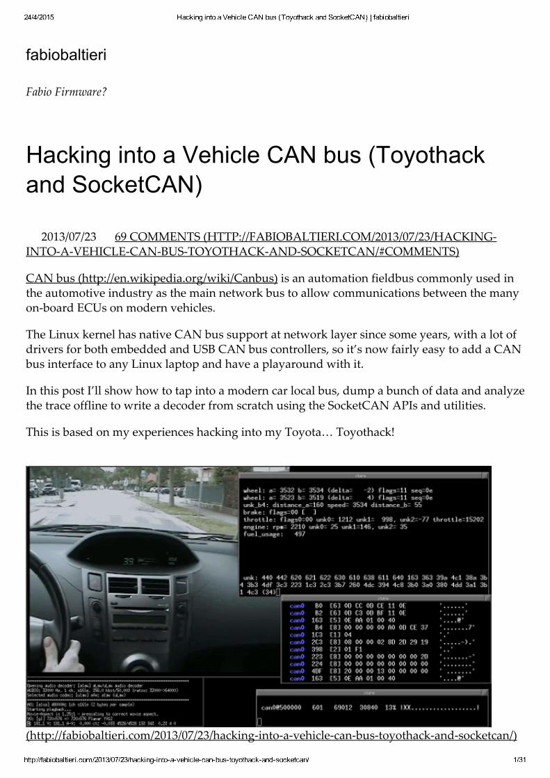
CAN bus (http://en.wikipedia.org/wiki/Canbus) is an automation fieldbus commonly used inthe automotive industry as the main network bus to allow communications between the manyon‑board ECUs on modern vehicles.
The Linux kernel has native CAN bus support at network layer since some years, with a lot ofdrivers for both embedded and USB CAN bus controllers, so it’s now fairly easy to add a CANbus interface to any Linux laptop and have a playaround with it.
In this post I’ll show how to tap into a modern car local bus, dump a bunch of data and analyzethe trace offline to write a decoder from scratch using the SocketCAN APIs and utilities.
This is based on my experiences hacking into my Toyota… Toyothack!
(http://fabiobaltieri.com/2013/07/23/hacking‑into‑a‑vehicle‑can‑bus‑toyothack‑and‑socketcan/)
24/4/2015 Hacking into a Vehicle CAN bus (Toyothack and SocketCAN) | fabiobaltieri
http://fabiobaltieri.com/2013/07/23/hackingintoavehiclecanbustoyothackandsocketcan/ 2/31
CAN bus Network Model
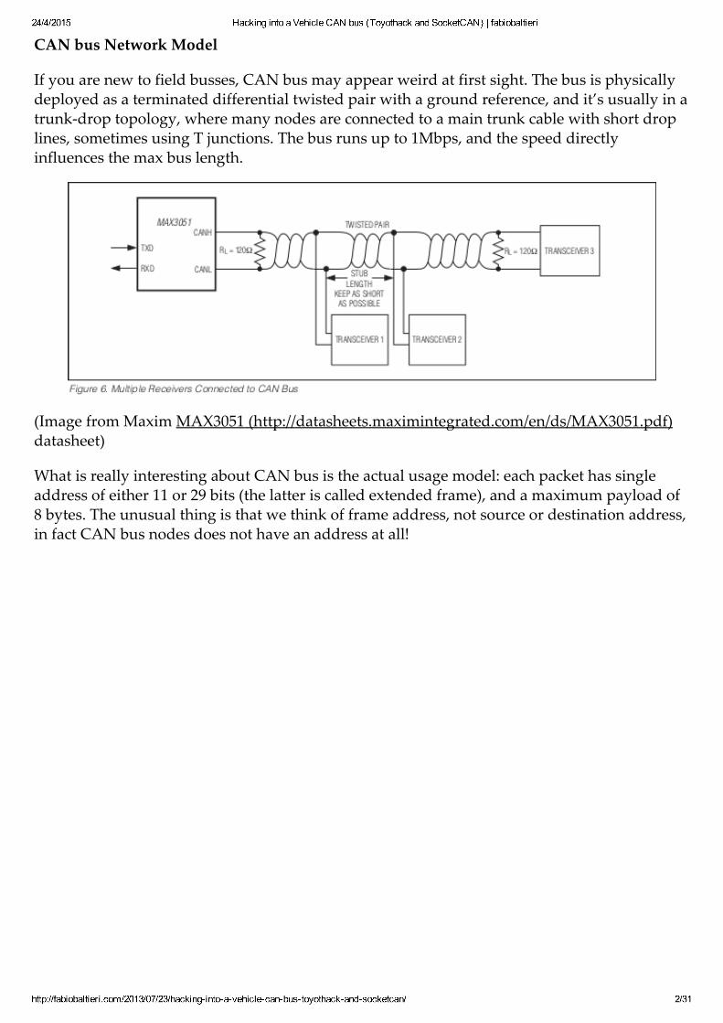
If you are new to field busses, CAN bus may appear weird at first sight. The bus is physicallydeployed as a terminated differential twisted pair with a ground reference, and it’s usually in atrunk‑drop topology, where many nodes are connected to a main trunk cable with short droplines, sometimes using T junctions. The bus runs up to 1Mbps, and the speed directlyinfluences the max bus length.
(Image from Maxim MAX3051 (http://datasheets.maximintegrated.com/en/ds/MAX3051.pdf)datasheet)
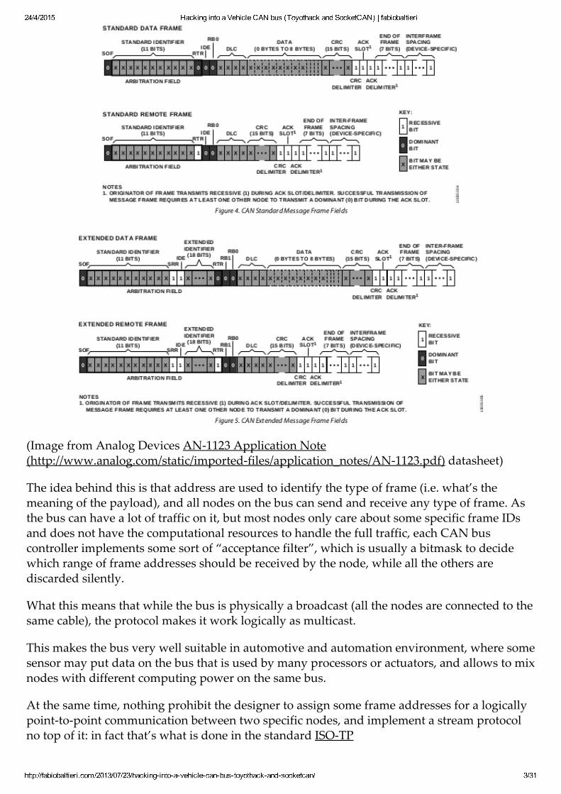
What is really interesting about CAN bus is the actual usage model: each packet has singleaddress of either 11 or 29 bits (the latter is called extended frame), and a maximum payload of8 bytes. The unusual thing is that we think of frame address, not source or destination address,in fact CAN bus nodes does not have an address at all!
24/4/2015 Hacking into a Vehicle CAN bus (Toyothack and SocketCAN) | fabiobaltieri
http://fabiobaltieri.com/2013/07/23/hackingintoavehiclecanbustoyothackandsocketcan/ 3/31
(Image from Analog Devices AN‑1123 Application Note(http://www.analog.com/static/imported‑files/application_notes/AN‑1123.pdf) datasheet)
The idea behind this is that address are used to identify the type of frame (i.e. what’s themeaning of the payload), and all nodes on the bus can send and receive any type of frame. Asthe bus can have a lot of traffic on it, but most nodes only care about some specific frame IDsand does not have the computational resources to handle the full traffic, each CAN buscontroller implements some sort of “acceptance filter”, which is usually a bitmask to decidewhich range of frame addresses should be received by the node, while all the others arediscarded silently.
What this means that while the bus is physically a broadcast (all the nodes are connected to thesame cable), the protocol makes it work logically as multicast.
This makes the bus very well suitable in automotive and automation environment, where somesensor may put data on the bus that is used by many processors or actuators, and allows to mixnodes with different computing power on the same bus.
At the same time, nothing prohibit the designer to assign some frame addresses for a logicallypoint‑to‑point communication between two specific nodes, and implement a stream protocolno top of it: in fact that’s what is done in the standard ISO‑TP

24/4/2015 Hacking into a Vehicle CAN bus (Toyothack and SocketCAN) | fabiobaltieri
http://fabiobaltieri.com/2013/07/23/hackingintoavehiclecanbustoyothackandsocketcan/ 4/31
(http://en.wikipedia.org/wiki/ISO_15765‑2) protocol, and there even is a SocketCAN exampleapplication to run a full Linux netdevice on top of it.
One additional feature is that the bus is designed so that lower frame addresses have an higherpriority when contending for the bus. This should be kept into account when designing thehigh level protocol, where often the address is segmented into fields, dedicating an higherportion as a “priority” indication.
CAN bus in Automotive
CAN bus was designed for the automotive environment, and that’s where it’s still widelydeployed. A modern car have many different ECUs and sensors, and the multicast nature ofCAN bus makes it ideal to distribute the data as needed.
Let’s take vehicle speed as an example, it is transmitted just once on the bus by some wheelsensor, and may be used at the same time by the dashboard, ABS, cruise control,radio/navigation and other devices.
Of course, some data and some nodes are more important than the others, and while CAN buscontroller implements some safety features such as error counters to self‑disconnect from thebus in case of errors, the bus itself can still suffer from a catastrophic failure, such as a cableshort or a cut in the middle.
For this reason, complex cars usually have more than one bus, often running at different speed.As an example that I found on a FIAT car, one bus is running at a relatively high speed(500kbps) and it’s wired only on the front of the car connecting critical systems, such as enginecontrol, ABS, power steering and so on. An additional bus runs at a much lower speed(50kbps), allowing for longer connection segments, and it’s only used by the non criticalequipments, such as dashboard, stereo, electric windows, lights, parking sensors etc. This oneis also wired into the CAN pair of the OBD diagnostic connector, making this easier to tap into.
All vehicle busses are usually connected to a common ECU at some point, which may be usedas a proxy to selectively transport some information between busses, while keeping thephysical isolation for safety reasons.
How the bus is laid out is specific to each car, so you may want to search for the servicemanual of a specific model, where you can usually found information on the physical bustopology. Some really complex installation may also spot additional LIN busses behind CANbus nodes… Do your own research!
On‑Board What??
OBD, or On‑board Diagnostics, is a set of standards to provide diagnosis and error reportingfrom the vehicle ECU.
The idea behind OBD is that as modern vehicles rely heavily on electronics and have a manyself test capability, a common protocol should allow a service center to read some standarderror code to help troubleshooting. Once an ECU detect some sensor value is out of a “safe”range, the system can store an error code and alert the driver by lighting up the well known

24/4/2015 Hacking into a Vehicle CAN bus (Toyothack and SocketCAN) | fabiobaltieri
http://fabiobaltieri.com/2013/07/23/hackingintoavehiclecanbustoyothackandsocketcan/ 5/31
“check engine” yellow light. At this point, a service center should be able to connect a genericscanner to the vehicle standard OBD port, and that should give a indication of what have failedin the vehicle history.
How’s that related to CAN bus? The OBD was originally implemented through some simplevendor‑specific protocol, at the point that when the standard OBD‑II connector was definedmany different busses, including CAN bus, were supported on the same cable, and a genericscanner needed to support all of those and guess which one is used on a specific vehicle (seeELM327 (http://elmelectronics.com/obdic.html#ELM327)).
Luckily enough, vehicle regulations become more specific over time, to the point that since2008, all car sold in the USA are required to implement OBD‑II in the CAN bus signalingvariant.
This means that in most (possibly all) modern cars, you can find a standard diagnosticconnector accessible somewhere near the dashboard, and on this connector you are sure to getaccess to one of the vehicle CAN bus.
So, what can you expect to find once you tap into that bus with your CAN bus interface? Youcan’t tell until you try, because apart from OBD data (which doesn’t send anything on it’s ownanyway), the bus can be used by the vendor for anything else: it may be the only bus of the car– in which case you get lots of data – or it may be dedicated for diagnosis, and in this case youget nothing at all.
If you are reading this just to have some fun and learn more about your car digital guts, you’llnot find OBD data that interesting, as that’s mostly diagnostic stuff. On the other side, if youmanage to attach and configure your interface correctly, turn on the ignition and see a flow ofdata, that means the bus you’re on is also shared with other vehicle ECUs, and that’s where thefun begins!
So, to sum up: most modern car have many digital busses, and at least one is a CAN bus andexposed on the standard diagnostics connector. You can attach a generic interface on it andsend access generic OBD data, but if the vendor decided to use that bus for something else,you’ll also find a stream of vendor‑specific frames, with real time sensor and controlinformation, waiting to be reverse engineered.
SocketCAN
On a CAN bus system you have a lot of self‑contained microcontroller/DSP based unitsconnected together, each one with its own acceptance filter and possibly injecting someinformation on the bus, but how does it step‑up to be used on a complex operating system?Enter SocketCAN.
SocketCAN (http://en.wikipedia.org/wiki/SocketCAN) is CAN bus stack for the Linux kernel,contributed by a team at Volkswagen Research (well done VW!), and it’s really ingenious inthat it implements CAN bus as a network device, exploiting many existing features of theLinux network stack.
What this means practically is that you are going to see your CAN bus controller as a networkdevice, controlled by the “ip” system command.
24/4/2015 Hacking into a Vehicle CAN bus (Toyothack and SocketCAN) | fabiobaltieri
http://fabiobaltieri.com/2013/07/23/hackingintoavehiclecanbustoyothackandsocketcan/ 6/31
That’s an example of how a CAN bus device appears on the system:
# ip link show dev can09: can0: <NOARP,UP,LOWER_UP> mtu 16 qdisc noqueue state UNKNOWN mode DEFAULT link/can
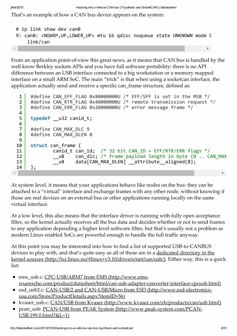
From an application point‑of‑view this great news, as it means that CAN bus is handled by thewell know Berkley sockets APIs and you have full software portability: there is no APIdifference between an USB interface connected to a big workstation or a memory mappedinterface on a small ARM SoC. The main “trick” is that when using a socketcan interface, theapplication actually send and receive a specific can_frame structure, defined as:
At system level, it means that your applications behave like nodes on the bus: they can beattached to a “virtual” interface and exchange frames with any other node, without knowing ifthose are real devices on an external bus or other applications running locally on the samevirtual interface.
At a low level, this also means that the interface driver is running with fully open acceptancefilter, so the kernel actually receives all the bus data and decides whether or not to send framesto any application depending a higher level software filter, but that’s usually not a problem asmodern Linux enabled SoCs are powerful enough to handle the full traffic anyway.
At this point you may be interested into how to find a list of supported USB‑to‑CANBUSdevices to play with, and that’s quite easy as all of those are in a dedicated directory in thekernel sources (http://lxr.linux.no/#linux+v3.10/drivers/net/can/usb/). Either way, this is a quicklist:
ems_usb.c: CPC‑USB/ARM7 from EMS (http://www.ems‑wuensche.com/product/datasheet/html/can‑usb‑adapter‑converter‑interface‑cpcusb.html)esd_usb2.c: CAN‑USB/2 and CAN‑USB/Micro from ESD (http://www.esd‑electronics‑usa.com/Store/ProductDetails.aspx?itemID=56)kvaser_usb.c: CAN/USB from Kvaser (http://www.kvaser.com/zh/products/can/usb.html)pcan_usb: PCAN‑USB from PEAK System (http://www.peak‑system.com/PCAN‑USB.199.0.html?&L=1)
1234567891011121314
#define CAN_EFF_FLAG 0x80000000U /* EFF/SFF is set in the MSB */#define CAN_RTR_FLAG 0x40000000U /* remote transmission request */#define CAN_ERR_FLAG 0x20000000U /* error message frame */ typedef __u32 canid_t; #define CAN_MAX_DLC 9#define CAN_MAX_DLEN 8 struct can_frame { canid_t can_id; /* 32 bit CAN_ID + EFF/RTR/ERR flags */ __u8 can_dlc; /* frame payload length in byte (0 .. CAN_MAX_DLEN) */ __u8 data[CAN_MAX_DLEN] __attribute__aligned(8);};
24/4/2015 Hacking into a Vehicle CAN bus (Toyothack and SocketCAN) | fabiobaltieri
http://fabiobaltieri.com/2013/07/23/hackingintoavehiclecanbustoyothackandsocketcan/ 7/31
usb_8dev.c: USB2CAN from 8 devices (http://8devices.com/usb2can)
Of all of this, I’ve only had experiences the EMS one, but that’s quite expensive and maybeharder to obtain, so the one I would buy right now is the USB2CAN from 8 devices: it’s cheap,you can get one from the webstore and they provide full schematics and firmware upgrades.There is also a repository with the actual device source code, but that’s hardly of any usewithout the correct programming environment.
As for my setup, I’m using my own open hardware USB AVR + MCP2515 interface. You canfind the repository for my design here (https://github.com/fabiobaltieri/open‑usb‑can), but theperformances are not that good above 250kbps, so I’m planning a complete redesign in thefuture.
What if I’m Stuck on Windows?
While I don’t usually consider this case, I’ve seen CANviaUSB (http://www.canviausb.com/)used in the development on a critical project and seems to be a great tool. So, if you really can’tavoid Windows, CANviaUSB is probably the free tool for you (the homepage contains a list ofsupported device).
Hacking Into the Bus
If you’ve read all the way through here I hope you’ve understood that you will have no idea ofwhat’s attached to the bus until you’ve analyzed it. This also means that you don’t know whatcan break once you start poking on it, so this may be a good time for a bit of a disclaimer:
You shouldn’t mess with your vehicle bus while it’s moving unless you are 100% sure ofwhat’s going on. The chance of breaking something critical is high and you can hurtsomeone (possibly yourself) if you mess up.
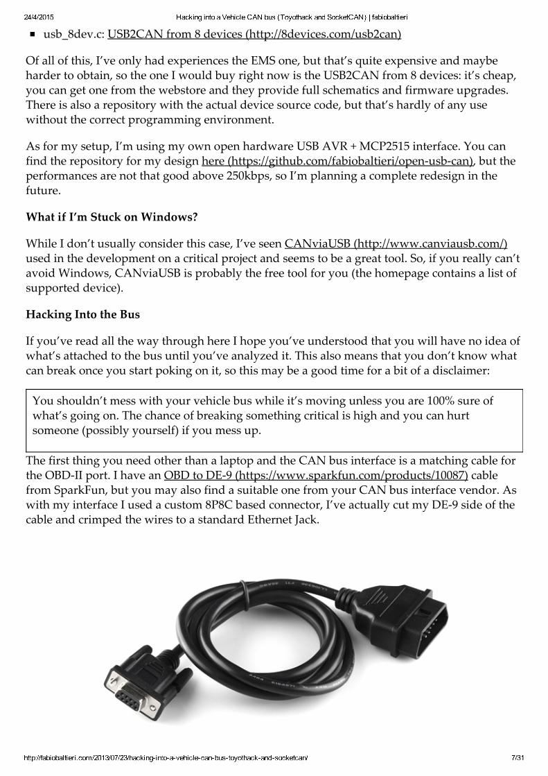
The first thing you need other than a laptop and the CAN bus interface is a matching cable forthe OBD‑II port. I have an OBD to DE‑9 (https://www.sparkfun.com/products/10087) cablefrom SparkFun, but you may also find a suitable one from your CAN bus interface vendor. Aswith my interface I used a custom 8P8C based connector, I’ve actually cut my DE‑9 side of thecable and crimped the wires to a standard Ethernet Jack.
24/4/2015 Hacking into a Vehicle CAN bus (Toyothack and SocketCAN) | fabiobaltieri
http://fabiobaltieri.com/2013/07/23/hackingintoavehiclecanbustoyothackandsocketcan/ 8/31
(Image from Sparkfun (https://www.sparkfun.com/products/10087))
You should check the cable and interface pinout twice before attaching to the vehicle, as thereare many signals on the connector, including a +12V and possibly some vendor specific ones.
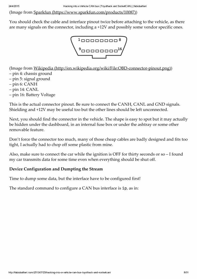
(Image from Wikipedia (http://en.wikipedia.org/wiki/File:OBD‑connector‑pinout.png))– pin 4: chassis ground– pin 5: signal ground– pin 6: CANH– pin 14: CANL– pin 16: Battery Voltage
This is the actual connector pinout. Be sure to connect the CANH, CANL and GND signals.Shielding and +12V may be useful too but the other lines should be left unconnected.
Next, you should find the connector in the vehicle. The shape is easy to spot but it may actuallybe hidden under the dashboard, in an internal fuse box or under the ashtray or some otherremovable feature.
Don’t force the connector too much, many of those cheap cables are badly designed and fits tootight, I actually had to chop off some plastic from mine.
Also, make sure to connect the car while the ignition is OFF for thirty seconds or so – I foundmy car transmits data for some time even when everything should be shut off.
Device Configuration and Dumpting the Stream
Time to dump some data, but the interface have to be configured first!
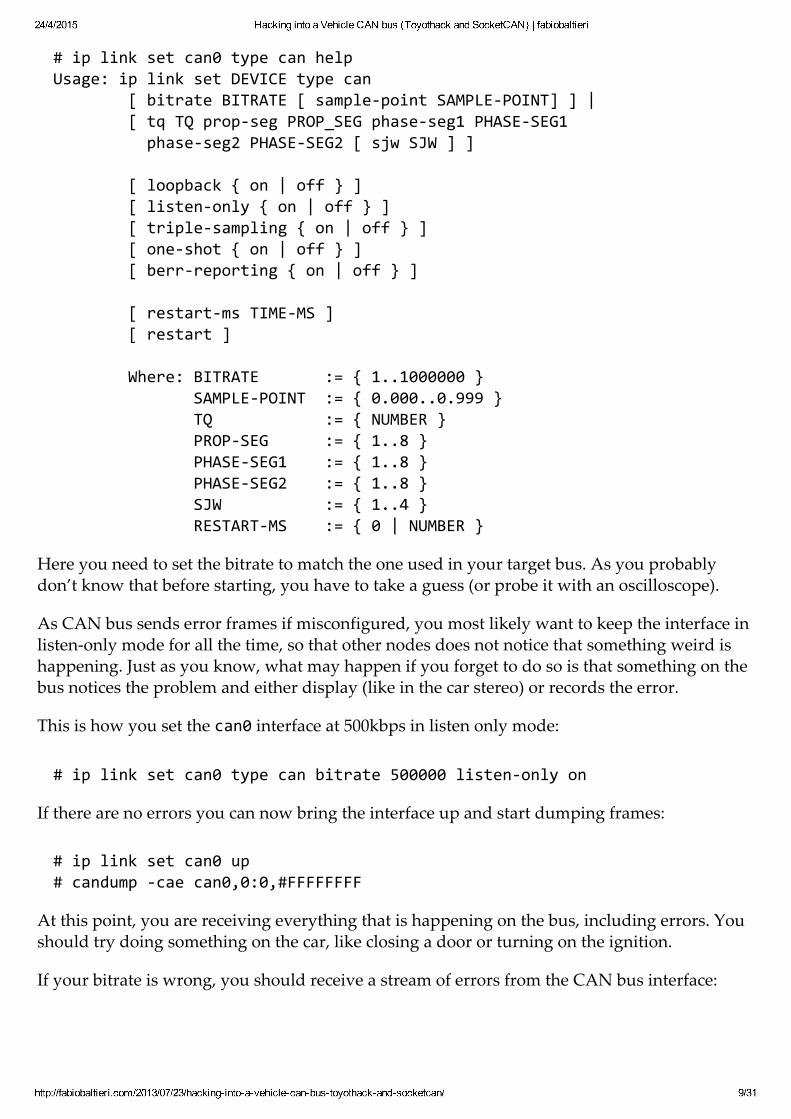
The standard command to configure a CAN bus interface is ip, as in:
24/4/2015 Hacking into a Vehicle CAN bus (Toyothack and SocketCAN) | fabiobaltieri
http://fabiobaltieri.com/2013/07/23/hackingintoavehiclecanbustoyothackandsocketcan/ 9/31
# ip link set can0 type can helpUsage: ip link set DEVICE type can [ bitrate BITRATE [ sample‐point SAMPLE‐POINT] ] | [ tq TQ prop‐seg PROP_SEG phase‐seg1 PHASE‐SEG1 phase‐seg2 PHASE‐SEG2 [ sjw SJW ] ]
[ loopback { on | off } ] [ listen‐only { on | off } ] [ triple‐sampling { on | off } ] [ one‐shot { on | off } ] [ berr‐reporting { on | off } ]
[ restart‐ms TIME‐MS ] [ restart ]
Where: BITRATE := { 1..1000000 } SAMPLE‐POINT := { 0.000..0.999 } TQ := { NUMBER } PROP‐SEG := { 1..8 } PHASE‐SEG1 := { 1..8 } PHASE‐SEG2 := { 1..8 } SJW := { 1..4 } RESTART‐MS := { 0 | NUMBER }
Here you need to set the bitrate to match the one used in your target bus. As you probablydon’t know that before starting, you have to take a guess (or probe it with an oscilloscope).
As CAN bus sends error frames if misconfigured, you most likely want to keep the interface inlisten‑only mode for all the time, so that other nodes does not notice that something weird ishappening. Just as you know, what may happen if you forget to do so is that something on thebus notices the problem and either display (like in the car stereo) or records the error.
This is how you set the can0 interface at 500kbps in listen only mode:
# ip link set can0 type can bitrate 500000 listen‐only on
If there are no errors you can now bring the interface up and start dumping frames:
# ip link set can0 up# candump ‐cae can0,0:0,#FFFFFFFF
At this point, you are receiving everything that is happening on the bus, including errors. Youshould try doing something on the car, like closing a door or turning on the ignition.
If your bitrate is wrong, you should receive a stream of errors from the CAN bus interface:
24/4/2015 Hacking into a Vehicle CAN bus (Toyothack and SocketCAN) | fabiobaltieri
http://fabiobaltieri.com/2013/07/23/hackingintoavehiclecanbustoyothackandsocketcan/ 10/31
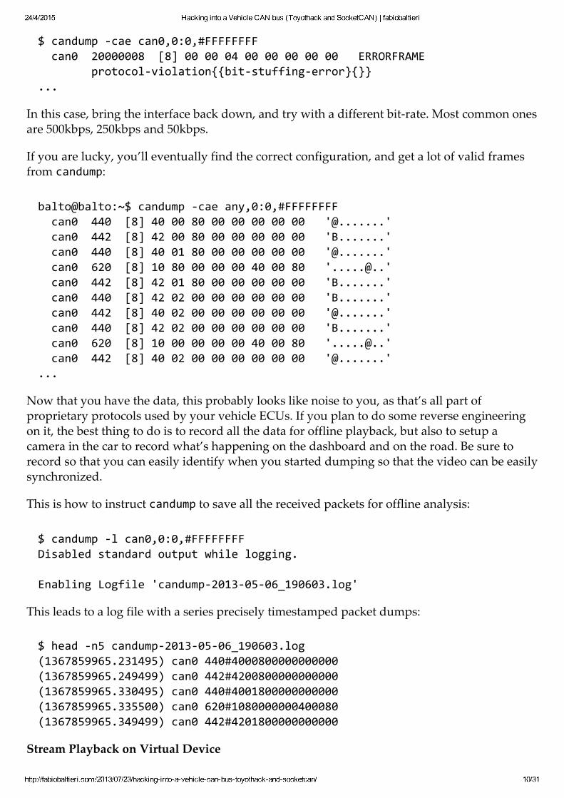
$ candump ‐cae can0,0:0,#FFFFFFFF can0 20000008 [8] 00 00 04 00 00 00 00 00 ERRORFRAME protocol‐violation{{bit‐stuffing‐error}{}}...
In this case, bring the interface back down, and try with a different bit‑rate. Most common onesare 500kbps, 250kbps and 50kbps.
If you are lucky, you’ll eventually find the correct configuration, and get a lot of valid framesfrom candump:
balto@balto:~$ candump ‐cae any,0:0,#FFFFFFFF can0 440 [8] 40 00 80 00 00 00 00 00 '@.......' can0 442 [8] 42 00 80 00 00 00 00 00 'B.......' can0 440 [8] 40 01 80 00 00 00 00 00 '@.......' can0 620 [8] 10 80 00 00 00 40 00 80 '.....@..' can0 442 [8] 42 01 80 00 00 00 00 00 'B.......' can0 440 [8] 42 02 00 00 00 00 00 00 'B.......' can0 442 [8] 40 02 00 00 00 00 00 00 '@.......' can0 440 [8] 42 02 00 00 00 00 00 00 'B.......' can0 620 [8] 10 00 00 00 00 40 00 80 '.....@..' can0 442 [8] 40 02 00 00 00 00 00 00 '@.......'...
Now that you have the data, this probably looks like noise to you, as that’s all part ofproprietary protocols used by your vehicle ECUs. If you plan to do some reverse engineeringon it, the best thing to do is to record all the data for offline playback, but also to setup acamera in the car to record what’s happening on the dashboard and on the road. Be sure torecord so that you can easily identify when you started dumping so that the video can be easilysynchronized.
This is how to instruct candump to save all the received packets for offline analysis:
$ candump ‐l can0,0:0,#FFFFFFFFDisabled standard output while logging.
Enabling Logfile 'candump‐2013‐05‐06_190603.log'
This leads to a log file with a series precisely timestamped packet dumps:
$ head ‐n5 candump‐2013‐05‐06_190603.log(1367859965.231495) can0 440#4000800000000000(1367859965.249499) can0 442#4200800000000000(1367859965.330495) can0 440#4001800000000000(1367859965.335500) can0 620#1080000000400080(1367859965.349499) can0 442#4201800000000000
Stream Playback on Virtual Device
24/4/2015 Hacking into a Vehicle CAN bus (Toyothack and SocketCAN) | fabiobaltieri
http://fabiobaltieri.com/2013/07/23/hackingintoavehiclecanbustoyothackandsocketcan/ 11/31
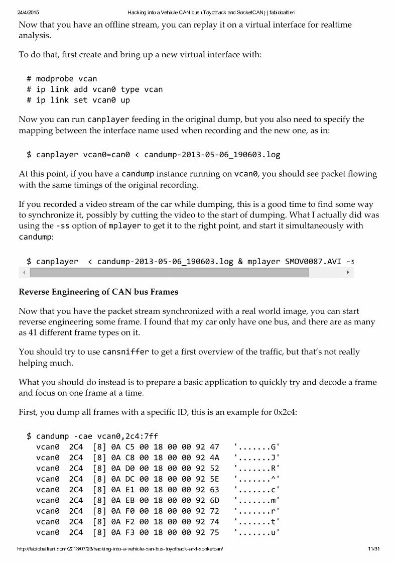
Now that you have an offline stream, you can replay it on a virtual interface for realtimeanalysis.
To do that, first create and bring up a new virtual interface with:
# modprobe vcan# ip link add vcan0 type vcan# ip link set vcan0 up
Now you can run canplayer feeding in the original dump, but you also need to specify themapping between the interface name used when recording and the new one, as in:
$ canplayer vcan0=can0 < candump‐2013‐05‐06_190603.log
At this point, if you have a candump instance running on vcan0, you should see packet flowingwith the same timings of the original recording.
If you recorded a video stream of the car while dumping, this is a good time to find some wayto synchronize it, possibly by cutting the video to the start of dumping. What I actually did wasusing the ‐ss option of mplayer to get it to the right point, and start it simultaneously withcandump:
$ canplayer < candump‐2013‐05‐06_190603.log & mplayer SMOV0087.AVI ‐ss 1:17
Reverse Engineering of CAN bus Frames
Now that you have the packet stream synchronized with a real world image, you can startreverse engineering some frame. I found that my car only have one bus, and there are as manyas 41 different frame types on it.
You should try to use cansniffer to get a first overview of the traffic, but that’s not reallyhelping much.
What you should do instead is to prepare a basic application to quickly try and decode a frameand focus on one frame at a time.
First, you dump all frames with a specific ID, this is an example for 0x2c4:
$ candump ‐cae vcan0,2c4:7ff vcan0 2C4 [8] 0A C5 00 18 00 00 92 47 '.......G' vcan0 2C4 [8] 0A C8 00 18 00 00 92 4A '.......J' vcan0 2C4 [8] 0A D0 00 18 00 00 92 52 '.......R' vcan0 2C4 [8] 0A DC 00 18 00 00 92 5E '.......^' vcan0 2C4 [8] 0A E1 00 18 00 00 92 63 '.......c' vcan0 2C4 [8] 0A EB 00 18 00 00 92 6D '.......m' vcan0 2C4 [8] 0A F0 00 18 00 00 92 72 '.......r' vcan0 2C4 [8] 0A F2 00 18 00 00 92 74 '.......t' vcan0 2C4 [8] 0A F3 00 18 00 00 92 75 '.......u'
24/4/2015 Hacking into a Vehicle CAN bus (Toyothack and SocketCAN) | fabiobaltieri
http://fabiobaltieri.com/2013/07/23/hackingintoavehiclecanbustoyothackandsocketcan/ 12/31
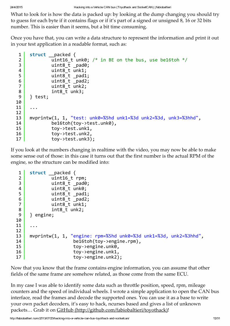
What to look for is how the data is packed up: by looking at the dump changing you should tryto guess for each byte if it contains flags or if it’s part of a signed or unsigned 8, 16 or 32 bitsnumber. This is easier than it seems, but a bit time consuming.
Once you have that, you can write a data structure to represent the information and print it outin your test application in a readable format, such as:
If you look at the numbers changing in realtime with the video, you may now be able to makesome sense out of those: in this case it turns out that the first number is the actual RPM of theengine, so the structure can be modified into:
Now that you know that the frame contains engine information, you can assume that otherfields of the same frame are somehow related, as those come from the same ECU.
In my case I was able to identify some data such as throttle position, speed, rpm, mileagecounters and the speed of individual wheels. I wrote a simple application to open the CAN businterface, read the frames and decode the supported ones. You can use it as a base to writeyour own packet decoders, it’s easy to hack, ncurses based and gives a list of unknownpackets… Grab it on GitHub (http://github.com/fabiobaltieri/toyothack)!
1234567891011121314151617
struct __packed { uint16_t unk0; /* in BE on the bus, use be16toh */ uint8_t _pad0; uint8_t unk1; uint8_t _pad1; uint8_t _pad2; uint8_t unk2; int8_t unk3;} test; ... mvprintw(1, 1, "test: unk0=%5hd unk1=%3d unk2=%3d, unk3=%3hhd", be16toh(toy‐>test.unk0), toy‐>test.unk1, toy‐>test.unk2, toy‐>test.unk3);
1234567891011121314151617
struct __packed { uint16_t rpm; uint8_t _pad0; uint8_t unk0; uint8_t _pad1; uint8_t _pad2; uint8_t unk1; int8_t unk2;} engine; ... mvprintw(1, 1, "engine: rpm=%5hd unk0=%3d unk1=%3d, unk2=%3hhd", be16toh(toy‐>engine.rpm), toy‐>engine.unk0, toy‐>engine.unk1, toy‐>engine.unk2);

24/4/2015 Hacking into a Vehicle CAN bus (Toyothack and SocketCAN) | fabiobaltieri
http://fabiobaltieri.com/2013/07/23/hackingintoavehiclecanbustoyothackandsocketcan/ 13/31
(http://github.com/fabiobaltieri/toyothack)
Finally, this is a video of what the final result looks like:
FILED UNDER HARDWARE, LINUX, NETWORKING TAGGED WITHAUTOMOTIVE, CANBUS, HACK, LINUX, OBD, SOCKETCAN, TOYOTA
About these ads (http://wordpress.com/abouttheseads/)
24/4/2015 Hacking into a Vehicle CAN bus (Toyothack and SocketCAN) | fabiobaltieri
http://fabiobaltieri.com/2013/07/23/hackingintoavehiclecanbustoyothackandsocketcan/ 14/31
69 Responses to Hacking into a Vehicle CAN bus (Toyothackand SocketCAN)
ildiopantofola says:2013/07/23 at 16:09Love it!!! *___*
ReplyDaniel says:2013/09/20 at 16:23Great job, I really admire all your projects, ideas and, of course, skills.
Replyfabiobaltieri says:2013/09/20 at 17:01Thanks Daniel!
Replymangodan2003 says:2013/11/08 at 13:42Hi there, great writeup! I am very interested in your open‑usb‑can project.
I have different hardware, an STM32f4 with 2 can controllers, I plan to eventually use bothby making my firmware present 2 USB interface descriptors .
For now I have been coding firmware in the hope that I can just use your kernel module, bymaking my hardware appear to be the same as yours from the host’s point of view.
I have got the device/interface/endpoint descriptors working, and can set the hw config,and start the interface. But I cannot figure out how you start the data flow. The urb’scallbacks in the kernel module do not seem to ever be called.
I can make data go out, for a short while using cangen, but never get anything back in.
I can see in the ep0.c control values that do not seem to ever be sent by the driver. Butwhich appear to be needed to start the data flow.
ATUSB_SPI_WRITE1/ATUSB_SPI_WRITE2andATUSB_SPI_READ1/ATUSB_SPI_READ2
The Write one seems to be the only place the ep in callback gets set.
Am I missing something?
Are these parts of the code actually used?
Thanks in advance, Dan
24/4/2015 Hacking into a Vehicle CAN bus (Toyothack and SocketCAN) | fabiobaltieri
http://fabiobaltieri.com/2013/07/23/hackingintoavehiclecanbustoyothackandsocketcan/ 15/31
Replyfabiobaltieri says:2013/11/08 at 20:18Hi Dan!
I was actually in the process of redesigning my open‑usb‑can with an STM32F103, as Iabandoned the AVR based design for performance reasons, but then I stalled the projectto work on other stuff…
Anyway, I’m happy that you’re using my kernel module as a base! That’s actually quitesimple because the firmware uses socketcan compatible data structures and you caneasily do the same. You may also be interested into a discussion on the linux‑can listabout USB‑CAN protocols (http://article.gmane.org/gmane.linux.can/2004) and maybeeven join the list!
The firmware code is actually based on the ATUSB Ben‑WPAN project (http://en.qi‑hardware.com/wiki/Ben_WPAN) so you may find some debugging/helper code stillthere and not used by the kernel module, and that’s the case for the ATUSB_SPI_* calls –the AVR to CAN controller SPI data is not exposed on the USB side for normaloperation.
As for the data flow, the stuff you find in ep0.c is only for the control endpoint(&eps[0]), and that’s used only for device configuration/start/stop. The actual bulktraffic is handled in buffer.c, where you can find references to usb_send(&eps[2], …) andusb_recv[&eps[1], …). Those two maps to the two kernel queues: usb_sndbulkpipe(dev‑>udev, 1) and usb_rcvbulkpipe(dev‑>udev, 2) and relative callbacks.
There may be a *ton* of reasons why your traffic doesn’t go trough, and you may wantto double check your descriptors and the hardware USB controller configuration on theSTM32, especially for the endpoint sizes.
In this situation I would search for an working example project to run on the STM32 thatuses bulk endpoint and adapt it to your configuration until you find what breaks. Onthe Linux side you can use the usbmon module to see the raw traffic. Also, one of myfavorite utilities for hacking on USB is the usbtool application from the v‑usb package,you can find it here https://github.com/obdev/v‑usb hidden into the examples/usbtooldirectory. It allows you send and receive arbitrary USB traffic, it uses libusb internally. Ifyou use that just keep in mind that it doesn’t flip between the DATA0/1 packet id, so itwill actually work only for the first packet… but that’s often enough! :‑)
Replymangodan2003 says:2013/11/09 at 11:19Thankyou for such an in depth reply.
I have managed to get data flowing to the host, it was something to do with the FIFObuffer settings, I do not fully understand how these are allocated and used at presentso need to investigate.I had based my CAN vender specific driver on the stm cdc example class, removing
24/4/2015 Hacking into a Vehicle CAN bus (Toyothack and SocketCAN) | fabiobaltieri
http://fabiobaltieri.com/2013/07/23/hackingintoavehiclecanbustoyothackandsocketcan/ 16/31
the command endpoint so I just have the control endpoint and two bulk end pointsas you do, but had over looked the FIFO settings.I have used lsusb with ‑v option to confirm the descriptors are all correct.
Although data flows to the host it is presently split in to tiny packets, I am onlysending 17 bytes and it seems to send this as 12 bytes followed by the remaining 5bytes.My wxPacket sizes for both the in and out Endpoint are set way higher thanthis, 64 and 32 bytes. So I have some work todo to find out why this is happening,but once resolved I am nearly there :).
I have been using usbmon module with wireshark, and also a libusb test programadapted from something else I found online. I will investigate the other things yousuggested.
Thanks again
Dan
ZeroAviation says:2014/02/03 at 18:07What kind of FIFO settings were you missing? I’m facing a similar problem.
ReplyArnold says:2013/11/12 at 17:16Hello.
Question: Can all cars engine be started by the OBD‑2 Conector using CAN bus protocol?
Replyfabiobaltieri says:2013/11/12 at 20:42Hi Arnold, I think quite the opposite: *maybe* some car can be started with some canpacket! Most cars probably still have a dedicated ignition circuit, and that’s evenwithout accounting for some key authentication, immobilizer etc… :)
ReplySam Crooks says:2013/11/23 at 21:52Fabio:
You might consider using a Beagle Bone Black with a CAN cape. You can then directly wireinto the CAN networks in the car permanently (all of them) and dump continuously,automate data collection, and also not block the OBD‑II port… Useful if you want to sniffout what dealer diagnostic tools are sending on the network, or ECU flash programmers.See my website for my project notes on taking this approach
http://the8thlayerof.net
Sam
24/4/2015 Hacking into a Vehicle CAN bus (Toyothack and SocketCAN) | fabiobaltieri
http://fabiobaltieri.com/2013/07/23/hackingintoavehiclecanbustoyothackandsocketcan/ 17/31
Replyfabiobaltieri says:2013/11/23 at 22:15Sure thing! The BBB is a great board for this kind of hacks and has a very capable CPUand a good design in general as you would expect from TI.
I actually worked in the past with the standard BB and with the AM335x CPU ingeneral, and I still think that it’s one of the best general purpose board/CPU available.
Thanks for the link! :‑)
ReplyChad Gibbons says:2013/12/30 at 00:29Great post and information. You inspired me to do something similar to my Jeep and theresults re here: http://chadgibbons.com/2013/12/29/hacking‑the‑jeep‑interior‑can‑bus/
Replyfabiobaltieri says:2013/12/30 at 00:47Thanks… and nice job on your Wrangler! :‑)
Replyjavad says:2014/02/02 at 10:57hi fabioI want send and recieve can data, but when this command ” ip link set can0 type can” is okbut when I run this command “ip set link can0 type can listen‑onl on” , operatiopn norsupporeted :‑(can you help me?
Replyfabiobaltieri says:2014/02/02 at 16:03Hi, looks like the device you are using does not support listen‑only mode. That’simplemented in the driver so you need an updated version or to do your ownimplementation.
ReplySarthak says:2014/02/21 at 11:47Hey Fabio,
How you doing? The work you have done is fantastic and exciting. Actually, I am trying toget access to the CAN packets transferred among different ECUs. I am not sure whathardware you are exactly using. From the blog, I guess that you are using an OBD to DB9cable, a laptop but what to connect the laptop and cable. Is it RJ45 port of the laptop you areusing ? Please help !!Thank you !!
24/4/2015 Hacking into a Vehicle CAN bus (Toyothack and SocketCAN) | fabiobaltieri
http://fabiobaltieri.com/2013/07/23/hackingintoavehiclecanbustoyothackandsocketcan/ 18/31
Replyfabiobaltieri says:2014/02/22 at 21:09Hi Sarthak, that’s explained in the post, my specific setup is a laptop, a custom usb‑to‑canbus interface and a modified OBD cable that fits my CAN interface (which happensto have an 8P8C connector but of course is not Ethernet). The software part is just thesocketcan and my test application.
You need to grab a CAN interface of some kind (USB are common nowadays) and anOBD cable, and modify the cable to fit the CAN interface pinout.
ReplySarthak says:2014/02/24 at 14:20Yes, I am using an OBD‑II UART board, FTDI Basic, Laptop and a standard OBD to DB9cable. But I am not able to figure out that when I will connect the USB port to the laptop,then how will I link the USB port i.e.COM1(for ex) with the the commands you mentionedin your blog to start the session. Please suggest.
Thank You !
Replyfabiobaltieri says:2014/02/24 at 23:10I think you have an ELM327 based board, that’s actualy designed to handle the OBDprotocol on‑chip and communicate with the host PC using AT commands. I think thatsome version is able to inject raw CAN frames, but AFAIK it does not work withSocketCAN, so it’s totally a different thing from what I cover in the post.
If you are looking into OBD you should search for some ELM327 specific tutorial, but ifyou are interested into raw CAN stuff and socketcan you should get a different CANinterface.
ReplyYousef says:2014/04/05 at 14:41Hi FabioI work with “PEAK‑SYSTEM‑ CAN card ” , I can connect two can interface, I generate CANdata in one can interface and dump can data in other inteface.but I want reverse engineering on PLD engine controller and dump can data in thiscontroller. you can find specific of this controller in this link(http://www.scribd.com/doc/57350358/PLD‑Manual‑MERCEDES‑INJECTORS‑FUEL‑SYSTEM)but I can not receive any data with my interface! however I can connect it with cardiagnostic and receive CAN data! I try to determine output signal with oscilloscope andsaw voltage level of this controller are 9 V & 12 V for CAN‑H and CAN‑L . but in myinterface output level are ‑1.5 and +1.5 V . if I can connect this controller with my interface ?how I should connect this controller physically? if I should run specific command forconnect and dump CAN data without “candump can0″? please help me :‑)thanks a lot.
24/4/2015 Hacking into a Vehicle CAN bus (Toyothack and SocketCAN) | fabiobaltieri
http://fabiobaltieri.com/2013/07/23/hackingintoavehiclecanbustoyothackandsocketcan/ 19/31
Replyfabiobaltieri says:2014/04/07 at 19:15Hi Yousef,
there are many things you should check to troubleshoot the problem: first make surethat you are able to display error messages from the CAN interface (candump has somespecific flags), then it may be possible that the bus you are using generates data onlywhen triggered (check for activity with the scope). It may be useful for you to build asplit cable to connect the diagnostic tool and your CAN interface at the same time, sothat you can check if you receive the same data from both.
For the voltage level, is actually quite high and may be saturating the transceiver. Youshould check which transceiver p/n is used in your CAN interface, and make sure itworks with common mode voltage as high as ~10V. Ideally you would also use anisolated interface (if you are on a laptop using it from the battery may be enough).
ReplyYousef says:2014/04/29 at 08:20Hi Fabiothanks a lot for you answers. I want connect to Mercedes Benz BUS and read CANdata from diagnostic connector. In your opinion are there difference between CANbus configuration of Buses and cars? can I receive CAN data similar way ?thanks a lot.Yousef
jon says:2014/04/09 at 23:49How could I control the climate in my Lexus Lx470? I am a beginner with Can‑bus and notsure where to begin.
Replyfabiobaltieri says:2014/04/10 at 00:06Well, that’s a long shot, I would not suggest you to wire up stuff to your car unless youknow what your are doing. :‑)
That said, it’s hard to say, if you can equip with the proper tools you would have to findthe correct bus, decode some control data and – if the protocol design allows – try toreinject it to control what you need.
Replymarius says:2014/05/29 at 06:57Firstly, what a great post. Thanks very much! I have quite a bit of experience with CAN,and always get the question how to read fuel consumption from many differentmanufacturer’s CAN bus. Yet, this signal is very difficult to reverse‑engineer, I find,
24/4/2015 Hacking into a Vehicle CAN bus (Toyothack and SocketCAN) | fabiobaltieri
http://fabiobaltieri.com/2013/07/23/hackingintoavehiclecanbustoyothackandsocketcan/ 20/31
because many other signals (engine torque for example) look very similar. I see you havefuel usage identified on the toyota. How could you be sure it is the right signal? Any tipswill be greatly appreciated! :‑) Again, thanks very much for an excellent article.
Replyfabiobaltieri says:2014/05/30 at 15:55Hello Marius!
Thanks for the comment, I agree that most of this is very hard to reverse engineer…Even after you isolated some counter, everything spins up as soon as you rev up theengine! :‑)
For the fuel consumption I’m afraid I found a hint on some other website for similarprojects on other Toyotas, and the value seems to change together with the instantconsumption on the dashboard. My first idea would be to try to see if the those twoupdates together but if that doesn’t work I guess you should compare with some othercar diagnostic tool.
Cheers!
ReplyPer says:2014/06/27 at 11:27Nice job on decoding the CAN‑frames.
Now that you have a CAN‑OBD‑interface it would be really simple to add functionality toalso log supported OBD‑PIDS for your vehicle
Have a look at http://en.wikipedia.org/wiki/OBD‑II_PIDs for a very nice guide. Basically,for the supported PIDS of your vehicle you just send a CAN‑message and wait forrespeonse. The list of supported PIDS is obtained by simpy asking, which is alwayssupported (for non‑electric vehicle).
Example:
Supported PIDs are obtained by sending a can message with [02,01,00,0,0,0,0,0], responecontains PIDS‑supported.
Lets say PID=0x0A (fuel pressure) is supported, just send [02,01,0A,0,0,0,0,0] and wait forresponse. Response should be something like: CAN‑Sender‑ID=0x7E8 (message from mainecu), [numBytes, 0x41, PID=0x0A, A, B, C ,D, E, …] and actual fuel pressure is A*3according to wikipedia.
Replyfabiobaltieri says:2014/06/27 at 20:09Hi Per!
You’re right, I was more interested into reversing some vehicle specific data but at this
24/4/2015 Hacking into a Vehicle CAN bus (Toyothack and SocketCAN) | fabiobaltieri
http://fabiobaltieri.com/2013/07/23/hackingintoavehiclecanbustoyothackandsocketcan/ 21/31
You’re right, I was more interested into reversing some vehicle specific data but at thispoint it would be cool to have a socket‑can based OBD scanner like you described…Only problem with that: in the meantime I moved to Ireland and I don’t have a caranymore! :)
Thanks for the followup though, feel free to drop a link if you have a chance of writingsomething for socketcan + OBD, I’m not aware of any free software to do that and itwould be great to start one!
Cheers,Fabio
ReplyMicheal Dada says:2014/09/12 at 20:29Great job! really like your project. I have a project i’m actually working on, it’s all aboutacquiring odometer protocols from canbus, was able to acquire protocols for some vehiclesbut still have problem getting from vehicles like toyota hilux, toyota hiace, mistibushi l200,mistibushi lancer, ford ranger and other ford series. Kindly help with tips on resolvingthese.
Replyfabiobaltieri says:2014/09/12 at 21:41Sweet! You are welcome! :‑)
ReplyBill K says:2014/09/16 at 20:34Thank you for this informative post. Although as a medical diagnostic imaging engineer Iam familiar with CAN bus, what I am working with is pretty much presented by themanufacturers in hardware and software, as is the case with OBD II and OBD II readers.Your presentation differs in that it probes down to the signal level, which then maydetermine if a component is actually bad or if the signal is just bad. Am I right?I wish you had described a step by step use of the “socket can” for us who are less familiarwith programming.Have you done any work into hacking the other CAN bus in cars, namely the Navigation‑Radio‑CD changer‑Telephone‑etc. can bus? From following the various automotive forumsthere seems to be an awful lot of problems in that area. I wonder why the power train CANis so reliable and the entertainment CAN is not. (Greater product liability?)
Replyfabiobaltieri says:2014/09/16 at 22:46Hi Bill! Yes you are just about right, I would not really say “signal” though as I did notreally put too much effort on electrical signals but rather at the lowest digital layer – theraw transmission and receiving of CAN frames, such as if they were IP packets.
The socketcan part is actually easy if you get familiar with normal “internet” sockets
24/4/2015 Hacking into a Vehicle CAN bus (Toyothack and SocketCAN) | fabiobaltieri
http://fabiobaltieri.com/2013/07/23/hackingintoavehiclecanbustoyothackandsocketcan/ 22/31
The socketcan part is actually easy if you get familiar with normal “internet” socketsbefore, and that is just the API used to interface applications with TCP and UDP (andmore!) streams. SocketCAN is just an extension of that to use CAN frames with the well‑known socket API, and it’s actually a huge step forward compared to previousimplementation of low level CAN APIs in Linux, which would not do too much otherthan exposing the controller to the application.
I did not really do much in cars other than what I described here, and I think CAN it’sused for infotrainment devices just because “it’s already there”… One problem is thatthere is still low interoperability between devices, since even if they share the bus theystill implement vendor specific protocols on top of it (think of after‑market stereo ordashboards).
If you hear about reliability problems it’s probably juts because those are just lessimportant busses and receive less attention to reliable design as a consequence… Maybethe cables and connectors are lower quality (gauge, twisting…), have longer trunks(worse signal integrity), moves through hinges and other stuff. I’m sure the drivetrainbus receive more attention and there’s much more than the protocol itself in designing areliable field bus system.
Cheers!
Replyxarxer says:2014/10/16 at 09:20Hi Fabio,
I just ordered an OBD‑II to DE‑9 cable to do some car hacking, but I’d like to get startedright away, so I was wondering if maybe you still have your recorded data? If so, I coulduse it to get the basics done of an application that utilizes it!
Thanks in advance!
Replyfabiobaltieri says:2014/10/16 at 20:17Hi Xarxer… I don’t have the dump anymore! :‑) Sorry!
Replymck1117 says:2014/12/10 at 07:40Could you grab another one? I’m also interested in a working dump. Surely you stillhave the car!
fabiobaltieri says:2014/12/10 at 20:06Nope, I moved shortly after writing this post and I don’t have a car anymore. :‑)
SpoderMan says:2015/01/03 at 07:30Hello Fabio,
24/4/2015 Hacking into a Vehicle CAN bus (Toyothack and SocketCAN) | fabiobaltieri
http://fabiobaltieri.com/2013/07/23/hackingintoavehiclecanbustoyothackandsocketcan/ 23/31
Very nice work! I am quite interested in this project, and very impressed by this write‑up. Iam wondering if you have messed with writing to the ECU to add any special “tunes” orperformance mods? I am wanting to take this approach to learn more about some newerdiesel trucks, and what signals/data are running on the CAN bus, perhaps write someperformance tunes in a C# program where they can then be uploaded via OBD.
Replyfabiobaltieri says:2015/01/03 at 19:24Hi! Not really, I’m afraid all the information on how to change stuff on the ECU ismodel specific and non standard, and I haven’t tried to write anything on the bus. Theidea should work, you can get some CAN interface with C# APIs and write stuff to thevarious ECUs, but you need to get or reverse the programming documentation first.
Replysarthak7386 says:2015/01/07 at 15:18Hey Fabio,
Hi! I am Sarthak Jain. I was currently analysing the CAN bus via ELM327. I captured somepackets for window up and down. But when I replay those packets using ELM327, then Ido not see any action other than flickering of ‘check engine light’. After asking some people,I came to know that the speed of ELM may be slow which is causing conflicts on the CANbus.I came across this module – http://www.8devices.com/usb2can. I need to know if I sendthose packets using this hardware, I would not get the same problem of speed as with ELM.Can you please comment upon this?There is one more module – ‘ECOM’ cable which is being used for hacking the CAN bus.Are you aware of this?
Thank you!
Replyfabiobaltieri says:2015/01/07 at 22:19Hi Sarthak! I have no experience with ELM327 but the speed explanation soundawkward (speed of what btw? the micro that the elm is based on? its CAN interface?). Ifyou are using the ELM correctly I think you could get the same result… but having asecond device to crosscheck would not hurt for sure. Never heard for this ECOM thing.
Replysarthak7386in says:2015/01/08 at 17:32Hey,
The speed is that of the CAN packets which I am sending via ‘pyserial’ package.Actually I am using OBD‑II UART board which provides a serial interface to send andreceive packets to the OBD‑II bus. I used ELM 327 AT commands to analyse the traffic,reverse‑engineered some of the packets, found the ones which change when, say window
24/4/2015 Hacking into a Vehicle CAN bus (Toyothack and SocketCAN) | fabiobaltieri
http://fabiobaltieri.com/2013/07/23/hackingintoavehiclecanbustoyothackandsocketcan/ 24/31
go up or down. But when I replay those packets using ‘pyserial’, all I get is ‘flickering ofcheck engine light’.By the way, USB2CAN device provides a serial interface or some other?
Replyfabiobaltieri says:2015/01/10 at 16:25Right, so if the OBD adapter is passing through a standard UART to communicate withthe host, it may be saturating that link. I think that’s a poor design in general, but it’sparticularly bad if it’s using a real UART and a converter, limited to a specific bit rate,rather than a “virtual serial” implemented directly on the USB controller. In the case ofthe ELM controller I guess that the design made sense since you are supposed to use itto communicate with the ELM chip using AT commands (let’s call it legacy), and thatlink should not require much bandwidth, but if you try to turn that into a CAN interfaceyou are surely going to get very poor performances. None of the devices I listed in thispost are implemented like that AFAIK, and all are using proper USB endpoints (andworks with socketcan).
That said, I doubt that’s the problem that leads to your “check engine flickering” thing,you are more likely sending wrong data or just sending something that gets quicklyoverridden by some other periodic frame on the bus.
Replysarthak7386 says:2015/01/17 at 20:24Hey, yeah you are right that my data is being overridden by some other frames.
I have one more question. The OBD‑II UART board is having MCP2551 CANtransreceiver and STN1110 as its controller. Clearly STN1110 is ELM based and is notCAN controller.But we can select CAN as one of its protocols and then we can talk to ecu and getsensors data. Right?It means it can talk to the CAN bus without any problem. But I guess the only issueis that of speed of the serial port which is causing trouble.I hope this trouble goes away by using USB2CAN device?
Thank you!
fabiobaltieri says:2015/01/17 at 23:00Well, the fact that you only have a CAN transceiver on the board means that theSTN1110 does have a hardware CAN interface (it’s probably some commercialmicrocontroller pre‑programmed and custom branded), and the controller can surelyoperate on a full‑speed bus (that’s 1Mbps), but that does not immediately translate inthe fact that you can use it as a generic CAN interface and transfer the whole datastream of the bus on the control interface (your serial). The serial port speed is surelythe first concern on that, but that’s far from being the only limitations. CAN basedmicros are designed with some kind of frame filter to be able to silently discard mostdata present on the bus, and only activate the CPU to process the essential frames. Ifyou use the micro as a bus sniffer, thus opening the filters to grab the whole data
24/4/2015 Hacking into a Vehicle CAN bus (Toyothack and SocketCAN) | fabiobaltieri
http://fabiobaltieri.com/2013/07/23/hackingintoavehiclecanbustoyothackandsocketcan/ 25/31
stream, the micro may not even have enough power to unqueue the frames fastenough to prevent overrun, and that may even happen if the bus is lightly loadedbut bursty.
Those ODB chips are nice in that they can implement the OBD protocols (on top ofCAN and other busses), but they are not designed to be used as a raw CAN snifferdevice (access the full bus data even in heavy load or bursty conditions – which as Iunderstand is what you are trying to achieve here). If that is what you want to doyou would surely have better results with something like the USB2CAN.
sarthak7386 says:2015/01/18 at 09:05Okay, I hope UsB2CAN solve the problem! By the way do you know what transreceiverand controller USB2CAN is using? I did not find any information on their website.
One more thing – If let say I replay the packets responsible for door lock , will I actually seethe doors unlocking themselves? If you have some literature on how ECUs communicate, Iwould be really thankful to you if share the same.
Thank you!
Replyfabiobaltieri says:2015/01/18 at 16:49They give complete schematics on the website: http://www.8devices.com/usb2can, thesetup is an MCP2551 + STR750FV2.
On the lock question, hard to say, it depends how the information on the frames isinterpreted… it may not be that easy, and you are still racing with the frames sent by theoriginal controller on the bus, and injecting/replying frames may or may not workdepending on how the protocol is designed. The very fact that your check engine lightblinks when you send stuff is telling you that something is detecting an erroneouscondition on the bus (checksum? sequencing?…) which then resolves with the normaltraffic.
I don’t have any literature for that, you may find something about the OBD stuff (whichAFAIK is a request‑response based protocol implemented on top of a pair of CAN IDs),but everything else is proprietary, vendor and model specific stuff… If you findsomething is either leaked or reverse engineered (well, this post is about reverseengineering it after all…).
ReplySarthak Jain says:2015/04/05 at 18:38Hey,
Some time back, we had a discussion about ELM327 speed issues. Now, I purchasedan USB2CAN converter from 8devices. After configuring the CAN interface, when Itried to use candump command, I got nothing from the car.
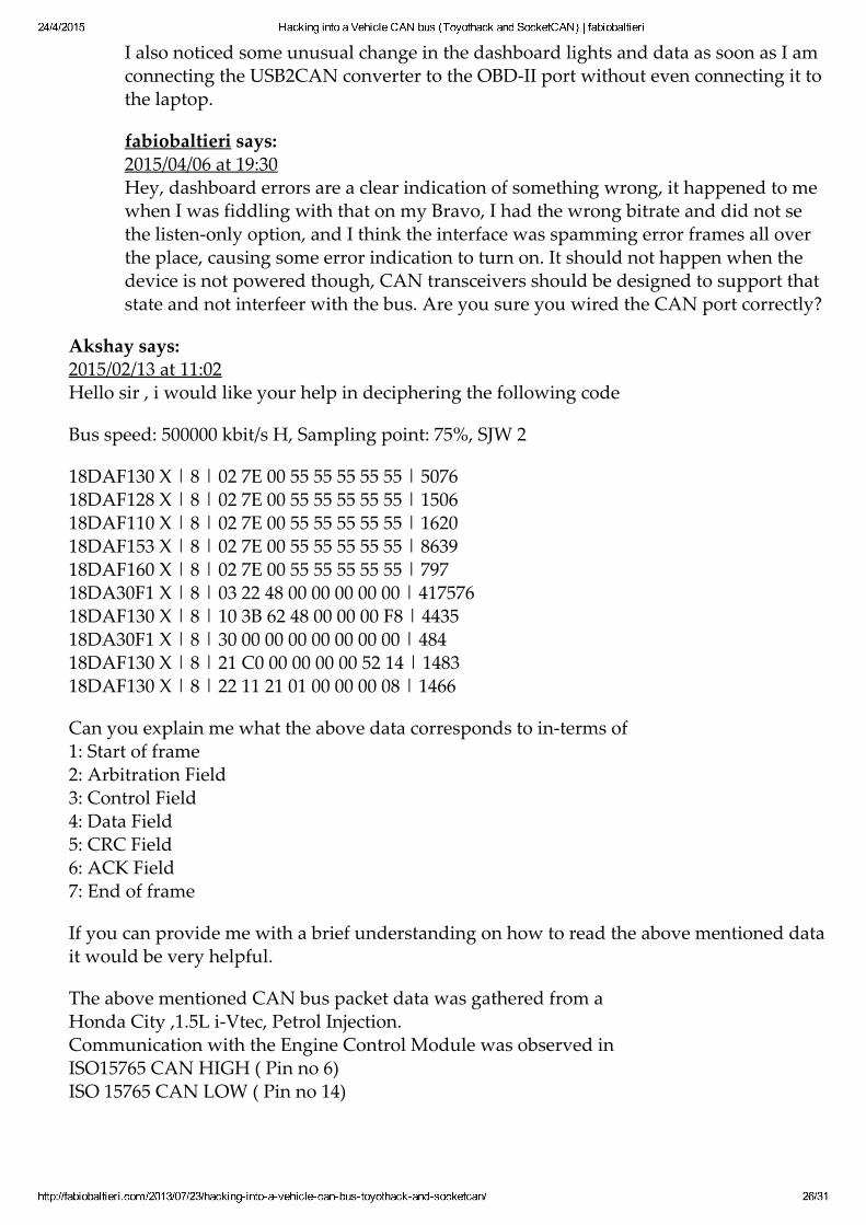
I also noticed some unusual change in the dashboard lights and data as soon as I am
24/4/2015 Hacking into a Vehicle CAN bus (Toyothack and SocketCAN) | fabiobaltieri
http://fabiobaltieri.com/2013/07/23/hackingintoavehiclecanbustoyothackandsocketcan/ 26/31
I also noticed some unusual change in the dashboard lights and data as soon as I amconnecting the USB2CAN converter to the OBD‑II port without even connecting it tothe laptop.
fabiobaltieri says:2015/04/06 at 19:30Hey, dashboard errors are a clear indication of something wrong, it happened to mewhen I was fiddling with that on my Bravo, I had the wrong bitrate and did not sethe listen‑only option, and I think the interface was spamming error frames all overthe place, causing some error indication to turn on. It should not happen when thedevice is not powered though, CAN transceivers should be designed to support thatstate and not interfeer with the bus. Are you sure you wired the CAN port correctly?
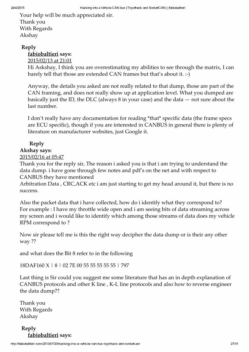
Akshay says:2015/02/13 at 11:02Hello sir , i would like your help in deciphering the following code
Bus speed: 500000 kbit/s H, Sampling point: 75%, SJW 2
18DAF130 X | 8 | 02 7E 00 55 55 55 55 55 | 507618DAF128 X | 8 | 02 7E 00 55 55 55 55 55 | 150618DAF110 X | 8 | 02 7E 00 55 55 55 55 55 | 162018DAF153 X | 8 | 02 7E 00 55 55 55 55 55 | 863918DAF160 X | 8 | 02 7E 00 55 55 55 55 55 | 79718DA30F1 X | 8 | 03 22 48 00 00 00 00 00 | 41757618DAF130 X | 8 | 10 3B 62 48 00 00 00 F8 | 443518DA30F1 X | 8 | 30 00 00 00 00 00 00 00 | 48418DAF130 X | 8 | 21 C0 00 00 00 00 52 14 | 148318DAF130 X | 8 | 22 11 21 01 00 00 00 08 | 1466
Can you explain me what the above data corresponds to in‑terms of1: Start of frame2: Arbitration Field3: Control Field4: Data Field5: CRC Field6: ACK Field7: End of frame
If you can provide me with a brief understanding on how to read the above mentioned datait would be very helpful.
The above mentioned CAN bus packet data was gathered from aHonda City ,1.5L i‑Vtec, Petrol Injection.Communication with the Engine Control Module was observed inISO15765 CAN HIGH ( Pin no 6)ISO 15765 CAN LOW ( Pin no 14)
Your help will be much appreciated sir.
24/4/2015 Hacking into a Vehicle CAN bus (Toyothack and SocketCAN) | fabiobaltieri
http://fabiobaltieri.com/2013/07/23/hackingintoavehiclecanbustoyothackandsocketcan/ 27/31
Your help will be much appreciated sir.Thank youWith RegardsAkshay
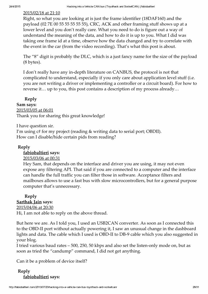
Replyfabiobaltieri says:2015/02/13 at 21:01Hi Askshay, I think you are overestimating my abilities to see through the matrix, I canbarely tell that those are extended CAN frames but that’s about it. :‑)
Anyway, the details you asked are not really related to that dump, those are part of theCAN framing, and does not really show up at application level. What you dumped arebasically just the ID, the DLC (always 8 in your case) and the data — not sure about thelast number.
I don’t really have any documentation for reading *that* specific data (the frame specsare ECU specific), though if you are interested in CANBUS in general there is plenty ofliterature on manufacturer websites, just Google it.
ReplyAkshay says:2015/02/16 at 05:47Thank you for the reply sir, The reason i asked you is that i am trying to understand thedata dump. i have gone through few notes and pdf’s on the net and with respect toCANBUS they have mentionedArbitration Data , CRC,ACK etc i am just starting to get my head around it, but there is nosuccess.
Also the packet data that i have collected, how do i identify what they correspond to?For example : I have my throttle wide open and i am seeing bits of data streaming acrossmy screen and i would like to identify which among those streams of data does my vehicleRPM correspond to ?
Now sir please tell me is this the right way decipher the data dump or is their any otherway ??
and what does the Bit 8 refer to in the following
18DAF160 X | 8 | 02 7E 00 55 55 55 55 55 | 797
Last thing is Sir could you suggest me some literature that has an in depth explanation ofCANBUS protocols and other K line , K‑L line protocols and also how to reverse engineerthe data dump??
Thank youWith RegardsAkshay
Replyfabiobaltieri says:
24/4/2015 Hacking into a Vehicle CAN bus (Toyothack and SocketCAN) | fabiobaltieri
http://fabiobaltieri.com/2013/07/23/hackingintoavehiclecanbustoyothackandsocketcan/ 28/31
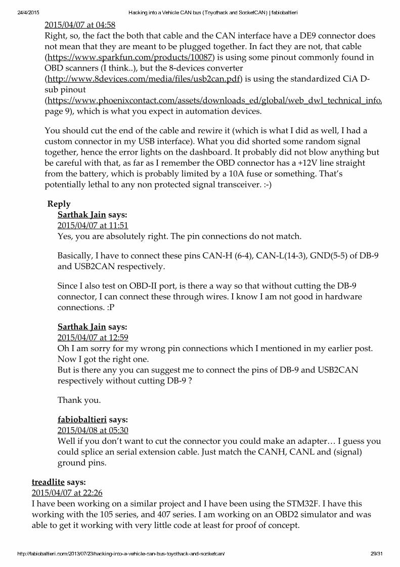
2015/02/18 at 21:10Right, so what you are looking at is just the frame identifier (18DAF160) and thepayload (02 7E 00 55 55 55 55 55), CRC, ACK and other framing stuff shows up at alower level and you don’t really care. What you need to do is figure out a way ofunderstand the meaning of the data, and how to do it is up to you. What I did wastaking one frame id at a time, observe how the data changed and try to correlate withthe event in the car (from the video recording). That’s what this post is about.
The “8” digit is probably the DLC, which is a just fancy name for the size of the payload(8 bytes).
I don’t really have any in‑depth literature on CANBUS, the protocol is not thatcomplicated to understand, especially if you only care about application level stuff (i.e.you are not writing a driver or implementing a controller or a circuit board). For how toreverse it… up to you, this post contains a description of my process already…
ReplySam says:2015/03/05 at 06:01Thank you for sharing this great knowledge!
I have question sir.I’m using c# for my project (reading & writing data to serial port; OBDII).How can I disable/hide certain pids from reading?
Replyfabiobaltieri says:2015/03/06 at 00:31Hey Sam, that depends on the interface and driver you are using, it may not evenexpose any filtering API. That said if you are connected to a computer and the interfacecan handle the full traffic you can filter those in software. Acceptance filters andmailboxes allows to use a fast bus with slow microcontrollers, but for a general purposecomputer that’s unnecessary.
ReplySarthak Jain says:2015/04/06 at 20:30Hi, I am not able to reply on the above thread.
But here we are. As I told you, I used an USB2CAN converter. As soon as I connected thisto the OBD‑II port without actually powering it, I saw an unusual change in the dashboardlights and data. The cable which I used is OBD‑II to DB‑9 cable which you also suggested inyour blog.I tried various baud rates – 500, 250, 50 kbps and also set the listen‑only mode on, but assoon as tried the “candump” command, I did not get anything.
Can it be a problem of device itself?
Replyfabiobaltieri says:
24/4/2015 Hacking into a Vehicle CAN bus (Toyothack and SocketCAN) | fabiobaltieri
http://fabiobaltieri.com/2013/07/23/hackingintoavehiclecanbustoyothackandsocketcan/ 29/31
2015/04/07 at 04:58Right, so, the fact the both that cable and the CAN interface have a DE9 connector doesnot mean that they are meant to be plugged together. In fact they are not, that cable(https://www.sparkfun.com/products/10087) is using some pinout commonly found inOBD scanners (I think..), but the 8‑devices converter(http://www.8devices.com/media/files/usb2can.pdf) is using the standardized CiA D‑sub pinout(https://www.phoenixcontact.com/assets/downloads_ed/global/web_dwl_technical_info/CANopen.pdfpage 9), which is what you expect in automation devices.
You should cut the end of the cable and rewire it (which is what I did as well, I had acustom connector in my USB interface). What you did shorted some random signaltogether, hence the error lights on the dashboard. It probably did not blow anything butbe careful with that, as far as I remember the OBD connector has a +12V line straightfrom the battery, which is probably limited by a 10A fuse or something. That’spotentially lethal to any non protected signal transceiver. :‑)
ReplySarthak Jain says:2015/04/07 at 11:51Yes, you are absolutely right. The pin connections do not match.
Basically, I have to connect these pins CAN‑H (6‑4), CAN‑L(14‑3), GND(5‑5) of DB‑9and USB2CAN respectively.
Since I also test on OBD‑II port, is there a way so that without cutting the DB‑9connector, I can connect these through wires. I know I am not good in hardwareconnections. :P
Sarthak Jain says:2015/04/07 at 12:59Oh I am sorry for my wrong pin connections which I mentioned in my earlier post.Now I got the right one.But is there any you can suggest me to connect the pins of DB‑9 and USB2CANrespectively without cutting DB‑9 ?
Thank you.
fabiobaltieri says:2015/04/08 at 05:30Well if you don’t want to cut the connector you could make an adapter… I guess youcould splice an serial extension cable. Just match the CANH, CANL and (signal)ground pins.
treadlite says:2015/04/07 at 22:26I have been working on a similar project and I have been using the STM32F. I have thisworking with the 105 series, and 407 series. I am working on an OBD2 simulator and wasable to get it working with very little code at least for proof of concept.
24/4/2015 Hacking into a Vehicle CAN bus (Toyothack and SocketCAN) | fabiobaltieri
http://fabiobaltieri.com/2013/07/23/hackingintoavehiclecanbustoyothackandsocketcan/ 30/31
My goal is to have a fully open source OBD2 simulator with all protocols. CAN was prettyeasy using the MCP2551 chips, but now I need to develop the others, specifically 9141 LINprotocol.
I am using the SN65HVDA195‑Q1 lin transiever, which I have also succsesfuly got workingon my own LIN network. Next goal is to get it working with the 5 baud init then switch tothe 10500, but I have run into a problem with time.
Would anyone be interested in working on the ISO 9141 OBD protocol?
BTW, I have been using the STM32F discovery boards. They use the STM32F407 and theyare only $15 from digikey.
Replyfabiobaltieri says:2015/04/08 at 05:38Is it an open source project? Link the code! :‑) Why do you care about ISO 9141? It’sbasically gone in new cars anyway…
Replytoyssan1 says:2015/04/08 at 17:58I will create a git repo and link it here in the next few days. It is very minimal codethough, but helping others with a jumping off point would be great…I myself amnot much of a developer.
Still a lot of cars on the road that are not CAN and will be for quite some time.
Mirsat Murutoglu says:2015/04/11 at 17:00Hi,
Thanks for your assistance to let us know more about CAN. I have used a phyton snifferand arduino can‑bus shiled to analyse the data. Im trying to figure out how aircon works. Ihave found all the related CAN‑BUS ids and datas for the aircon. When i send them back itdoesn’t care my data it keeps sending its own data. I used this way to lock unlock the doors,open the windows, move the seats, lights and so on. i used the aircon id and data for samebrand car but different model it worked. I wonder that it maybe LIN‑BUS or somethingelse? here is my id and sample data for fan level and temperature:CAN ID: 856, data: 0, 0, 0, 0, 21, 21, 153, 17CAN ID: 856, data: 0, 0, 0, 0, 21, 21, 153, 34CAN ID: 856, data: 0, 0, 0, 0, 21, 21, 153, 51
17,34 and 51 are for fan level and 21 is for temperatureThe car is 2015 Model.
Replyfabiobaltieri says:2015/04/12 at 23:18
Hi Mirsat, no idea how to help you, CAN connected ECU typically works by sending
24/4/2015 Hacking into a Vehicle CAN bus (Toyothack and SocketCAN) | fabiobaltieri
http://fabiobaltieri.com/2013/07/23/hackingintoavehiclecanbustoyothackandsocketcan/ 31/31
Hi Mirsat, no idea how to help you, CAN connected ECU typically works by sendingthe data on the bus periodically, so the one you are injecting is probably beingimmediately overwritten by the original one. It may work if the data is not periodic, so itmay be that the same frame is used in different way in different versions of the ECU(maybe in one version is periodic and some other is not).
ReplyMirsat Murutoglu says:2015/04/13 at 07:03Actually both cars send the same data and same id periodically but one is responding mydata other one is keep sending its own data and do its way. Even i send my data more thanthe original one.
Replyfabiobaltieri says:2015/04/14 at 20:12That’s awkward… no idea what’s going on there.
ReplyMirsat Murutoglu says:2015/04/15 at 09:14Yepp thats what i am trying to do ,I will let you know if i do it. Thanks
Sarthak Jain says:2015/04/21 at 05:28Hey,
I was able to get the data from the car via USB2CAN converter.
‘candump’ is working fine but when I use ‘cansend’ in a while loop, it is showing an error –“write:no buffer space”.
Can you comment on this?
Replyfabiobaltieri says:2015/04/23 at 18:26That happens if no devices on the bus are acknowledging a frame in the tx queue. Areyou transmitting on the car bus or on a loopback interface?
Reply
Blog at WordPress.com.
The Enterprise Theme.