Embed Size (px)
Citation preview

Petroleum & Petrochemical Engineering JournalISSN: 2578-4846
MEDWIN PUBLISHERSCommitted to Create Value for Researchers
The Impact of Offshore Environment on Drillship Positioning and Operations during Drilling the First Exploratory Well in Lebanon
Pet Petro Chem Eng J
The Impact of Offshore Environment on Drillship Positioning and Operations during Drilling the First Exploratory Well in Lebanon
Mhanna A1, Halafawi M2*, El Dilbani A3, Albulescu M2 and Avram L2
1GSP Offshore Company, Romania2Petroleum-Gas University of Ploiesti, Romania3GEOLOG Service Company, Romania *Corresponding author: Mohamed Halafawi, Petroleum-Gas University of Ploiești, B-dul Bucureşti, nr. 39, cod 100680, Ploieşti, Romania, Tel: 0040799641954, Email: [email protected]
Research ArticleVolume 5 Issue 3
Received Date: September 06, 2021
Published Date: September 30, 2021
DOI: 10.23880/ppej-16000276
Abstract
The offshore drilling activities in Lebanon have been started since 2020. All studies regarding the drilling operations and the environmental conditions become inevitable. Therefore, the objective of our paper is to study the marine environment in the region where a drillship called TUX was used to drill the first exploratory well in Lebanon. The effect of wind and wave on the drillship was studied using two predictive techniques: WW3 and ERA5. Furthermore, both techniques were used in order to predict the climate environmental conditions during the period where the TUX are positioned and performed drilling Well B4-1 in Block 4. The computed conditions of weather forecasting are wave and wind lengths, speeds, and heights. Spider plots were constructed in order to show the behavior of the sea waves during positioning and operating the TUX rig. Additionally, the impact loads produced from the wind was computed using several models and methods. A comparison between these methods was also done to show the accuracy of models. Lastly, the developed studies are very usefully so as to determine the safe conditions and periods for positioning the drillship to keep its stability.
Keywords: Drillship; Wind; Wave; ERA5; WW3; stability; Lebanon
Introduction
Drillship is simply a shipshape unit with a moonpool part or area used for drilling activities. The hollowed out part has various locations but the most common position is in the center of the drillship. The drillships power system is used to position this area, which is used for lowering and raising equipment into or from the water, and maintain it within pre-established limits. Although they are the most movable of all drilling units, their productivity is the least one. They are usually utilized for purposes of the remote offshore wildcat drilling operations, extremely deep-water drilling, or any other marine scientific exploration. They are being used widely to cover the gap between the jack-up rig
and the semisubmersible rig. However, they are drilling in the deepest water, over 1000 ft [1-4].
The main environmental loads on any mobile drilling units and other marine structures are the forces coming from wind, wave, and current. The action of natural movements make the offshore units to be forced off their location. A mooring system, which is consisted of up to 10 mooring lines and anchors, is used in order to offset these forces in any orientation. The placement and retrieval of this system is not easy and risky because it cannot be carried out safely more than 8 to 10 ft in waves. Therefore, the drilled water depth of the drillships is restricted merely by their mooring system. They are fixed on location either by the traditional mooring
Petroleum & Petrochemical Engineering Journal 2
Halafawi M. The Impact of Offshore Environment on Drillship Positioning and Operations during Drilling the First Exploratory Well in Lebanon. Pet Petro Chem Eng J 2021, 5(3): 000276.
Copyright© Halafawi M.
system or by dynamic positioning like the semisubmersible rigs. Nevertheless, the only additional system developed on them is called ‘turret’ system which is known as a bearing system. This permits the floating mobile vessel to rotate around a permanent geostatic part that is linked to the mooring system [1-4].
On the other hand, another technique of the drillships’ deployment is the dynamic positioning which needs a computer- monitoring system. This system will sense the vessel’s location relative to the well and orient the thrust of the propelling units to keep in the proper position. The required power to maintain position by dynamics means rapidly raise under excessive environmental loads. Thus, the dynamically suited vessels are not specially located for activities in areas of harshly water conditions [1-4].
The optimum water depth for doing activities and operation using the conventional mooring (lines and anchors) and dynamic mooring systems varies in the 1500 ft water depth domain. The conventional mooring system is the least expensive to be built on the drillships among the other floating units. The inclusion of dynamic system besides another conventional one increases basically establishment cost because there is no other alternative available nowadays for ultradeep water [2,4].
Regarding pros and cons of drillships, they have several advantages such as capability of transporting much bigger loadings of drilling supplies, proved their capability in deepwater, quickly travelling time to remote fields, self-propelled and then no need for tug. On the other way, the disadvantage of drillships is the only use in regions of small wave heights and low wind velocities. That means they are susceptibility to wave movement or action. With the language of number, they may heave 8 to 10 ft when the wave’s height is between 20 and 25 ft. Furthermore, when the heave reaches more than 5 to 7 ft; drilling operations are frequently stopped or suspended. Therefore, the drillship spend much more time as waiting on weather (WOW) in severe-water regions [1-4].
Marine Environment
In describing the offshore operation and activities in a marine environment, it is known that offshore operations are more complicated than those onshore. This complexity is produced due to harsh conditions of the marine environment. The offshore environment, which contains meteorological and oceanographic data other than tectonic movements and environmental conditions, influences on everything offshore. This effect starts from the marine platforms’ design, offshore pipelines and terminals for making planning, installation and repairs ways. Moreover, experts working in this fields
are usually contacted in order to determine the relevant conditions of meteorology and oceanography affecting a platform field [2,3]. Therefore, it is highly inevitable to study the marine conditions of the zone in which the drillships are going to start drilling or any activities before they go there and during operations. There are several researchers who have published since decades ago scientific researches, articles, and textbooks explaining the drillships design, installation, and maintenance procedures. They explained various loads, environmental conditions, positioning techniques, and stability of the drillships. Recently, Kukkanen presented the hydrodynamic wave loads and their prediction for marine structures in order to analyze the ultimate and fatigue strength. Furthermore, various methods were used so as to predict the wave loads and show their impact on offshore units [5]. Two year later, a Case Study from Lake Brownwood, Texas has been published so that the Impact of wind and wave action could be investigated on floating dock anchorage systems. The investigations of the structure forensic helped to detect the damage of 22 floating platform units resulting from blowing straight-line winds on May 8, 2009. Additionally, an evaluation of the anchorage systems has been done in order to test their effectiveness in resisting and withstanding different dynamic wave and wind situations in the large open water lakes [6]. In 2014, two researches appeared for studying different marine environmental conditions on the offshore structures and units. Firstly, Heij and Knapp [7] investigated the influences of wind strength and wave height coming from weather-related incidents and pollution incidents on six ship incident risk on different six regions all over the world. They found that their effect was changing with varying the type of the ship, period, season, and region [7]. On the other hand, the second study presented the influences of the marine wind farm on wave conditions and the shoreline development. A high energetic offshore environment of waves has been also studied. Furthermore, the effect of decreasing wind speed of its marine farm has been investigated in modeling the spectral wind-wave [8]. By 2015, a dynamics analysis method was used to study the stress and deformation of a drillship motion so that the stability of the marine heave compensator could be evaluated and diagnosed. This study helped to select the safety of the structure and simulate the structure stability [9]. After one year, a design stability of MODU with ship-shaped was studied which resulted from a heel moment graph of the wind. The stability considerations and requirements have been presented. Further, a building block method was used in order to determine wind forces and the heeling moment. Various considerations have also been discussed for each step of designing the drillships including wind tunnel tests [10].
On the last three years, scientific researches and simulation studies have become more complicated and
Petroleum & Petrochemical Engineering Journal 3
Halafawi M. The Impact of Offshore Environment on Drillship Positioning and Operations during Drilling the First Exploratory Well in Lebanon. Pet Petro Chem Eng J 2021, 5(3): 000276.
Copyright© Halafawi M.
advanced to keep pace with the developments of our era. Therefore, methods to determine the offshore environmental loads were introduced such as current, wind, and wave loads for A DP3 Drillship in 2019. A nonlinear restricted optimization problem was developed and solved by using the SQP method. Moreover, a comparative study between Static and Time-Domain Simulation Methods was done to analyze DP results of the drillship positioning, movement track, and the time of the force and direction signals of all thrusters [11]. Subramanian, et al. [12] presented a dynamic analysis study to investigate the behavior of a suction stabilized floating (SSF) platforms. Authors have modeled and simulated the dynamics of SSF platforms using numerical techniques in order to do their stability analysis. Furthermore, they could prevent catastrophic damages to marine units resulting from parametric resonance of ocean waves. Recently, Sutulo and Guedes [13] have analytically reviewed manoeuvrability criteria and standards of ships. Possible approaches to extend the current standards to embrace various situations sea and wind conditions were particularly presented including those related to the directional stability as possible solutions. They found that the introduction of new and additional standards are useful for developing a theoretical basis and obtaining analytical solutions set related to wind steady motions and data analysis of wind tunnel using conservative equations.
Therefore, this paper aims to study the impact of marine environment on the drillship during positioning and drilling operation in Lebanon. Different offshore environmental conditions are studied during drilling the first offshore well in Lebanon. These conditions include the effect of wind, current and wave on the drillship.
Techniques for Predicting Offshore Conditions
Marine environmental conditions are those situations when the weather is changing and hence the wind, current and wave are varying. This variation creates several impacts on any offshore unit or structure during installation and operations. Mathematics and governed equations describing these conditions have analytically been introduced and discussed in details [4,14]. Recently, an actual case study showed the impact of these conditions on a jackup rig was published by Halafawi, et al. [15]. They used the analytical equations in order to determine the marine environmental conditions: wave, wind, and current. However, our study will here show the same study but on drillship and with various techniques. The techniques are WW3 and ERA5.
WW3 Technique: The Wave Model
WW3 expresses an integrated spectral wave modeling. Recently, it contains the newest scientific developments
regarding wind-wave modeling and dynamics. Initially, its framework consists of a 3rd generation wave model established for predicting environmental conditions at the US National Centers (NOAA/NCEP) [16]. Currently, the present framework is developed from the initial packages of WW I&II model [17,18], and differs from first ones in several essential points such as model structure, governing equations, physical parameterizations, and numerical methods [14]. The governing equations is solved based on the 1st and the 3rd order precise numerical system. Although the WW3 is used for wave modelling, the physics of breaking waves are not modeled. Therefore, the model applicability of this method is outside on large scale and bigger surf zones [19]. However, there are some assumptions taken into consideration that can help to model those shallower-water areas [14]. The WW3 model gives predicted values of significant waves’ height on connected areas with the related wave directions and periods. Moreover, spectral data regarding the wave energy are available at the various wavelengths.
Governing equations The change rates of the wave phase parameters for
steady state can be determined based on the quasi-uniform (linear) wave theory [17,20,21].
( )2íó =gk tanh kd (1)
ù =ó+k.U (2)
The phase function of the wave component can define kv and ω from while the wave crests number is kept constant as follows [21,22]:
0ktν ω
∂+∇ =
∂ (3)
However, the situation is completely different for irregular wind waves. The random discrepancy of the sea surface is described utilizing the surface elevation of the change density spectrum F. During wave modeling, the term ‘’energy spectrum’’ is always used. Further, the spectrum F = f(k, σ, ω) that means it is a function of independent parameters. Moreover, F = f(k, σ, ω; x, t) that means it changes in space and time at larger scales [14]. The main spectrum in WW3 model is the wave number direction spectrum F(k, θ). This spectrum (F(k, θ)) was chosen due to its constant properties with respect to wave development physics and deterioration for variable water depths. The WW3 produces more conventional frequency-direction spectrum F(fr, θ) as modeling outputs. The various spectra can be determined from F(k, θ) by using straight-forward Jacobian conversions as follows [14]:
(4)
Petroleum & Petrochemical Engineering Journal 4
Halafawi M. The Impact of Offshore Environment on Drillship Positioning and Operations during Drilling the First Exploratory Well in Lebanon. Pet Petro Chem Eng J 2021, 5(3): 000276.
Copyright© Halafawi M.
(5)
Where cg is the group velocity and equals:
1,2 sinh2g
kdC n nk kd
σ σσ∂
= = = +∂
(6)
Details of WW3 modeling regarding model structure, solution of governing equations, physical parameterizations, and the required numerical methods are presented and fully explained in WW3 manual [14].
ERA5 Model: The Wind Model
ECMWF has produced several ways in order to analyze and monitor the climate change of a certain era or period. One of these techniques is ERA5 which has been produced so as to investigate and reanalyze the global climate since 1980. ERA5 means that it is the 5th generation of ECMWF. ERA5 re-analysis provides a numerical description of the latest climate by integrated models of traditional meteorological measurements as inputs with observations so that a better resolution can be obtained. Furthermore, ERA5 components can be provided annually, monthly, daily, and hourly. It also predicts several parameters as an output of the model such as 10m-wind direction, 10m-wind speed, wind gust, pressure, temperature, and another new parameters like 100-metre
wind speed and direction [23-26].
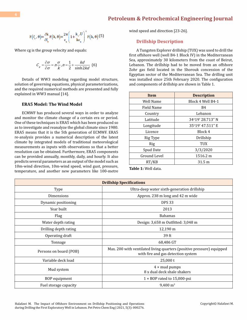
Drillship Description
A Tungsten Explorer drillship (TUX) was used to drill the first offshore well (well B4-1 Block IV) in the Mediterranean Sea, approximately 30 kilometers from the coast of Beirut, Lebanon. The drillship had to be moved from an offshore Zohr gas field located in the Shorouk concession of the Egyptian sector of the Mediterranean Sea. The drilling unit was installed since 25th February 2020. The configuration and components of drillship are shown in Table 1.
Item DescriptionWell Name Block 4 Well B4-1Field Name B4
Country LebanonLatitude 34o19’ 28.713” N
Longitude 35o19’ 47.511” ELicence Block 4
Rig Type DrillshipRig TUX
Spud Date 3/3/2020Ground Level 1516.2 m
RT/KB 31.5 mTable 1: Well data.
Drillship SpecificationsType Ultra-deep water sixth-generation drillship
Dimensions Approx. 238 m long and 42 m wideDynamic positioning DPS 33
Year built 2013Flag Bahamas
Water depth rating Design: 3,658 m Outfitted: 3,048 mDrilling depth rating 12,190 m
Operating draft 39 ftTonnage 68,486 GT
Persons on board (POB) Max. 200 with ventilated living quarters (positive pressure) equipped with fire and gas detection system
Variable deck load 25,000 t
Mud system 4 × mud pumps8 x dual deck shale shakers
BOP equipment 1 × BOP rated to 15,000-psiFuel storage capacity 9,400 m3
Petroleum & Petrochemical Engineering Journal 5
Halafawi M. The Impact of Offshore Environment on Drillship Positioning and Operations during Drilling the First Exploratory Well in Lebanon. Pet Petro Chem Eng J 2021, 5(3): 000276.
Copyright© Halafawi M.
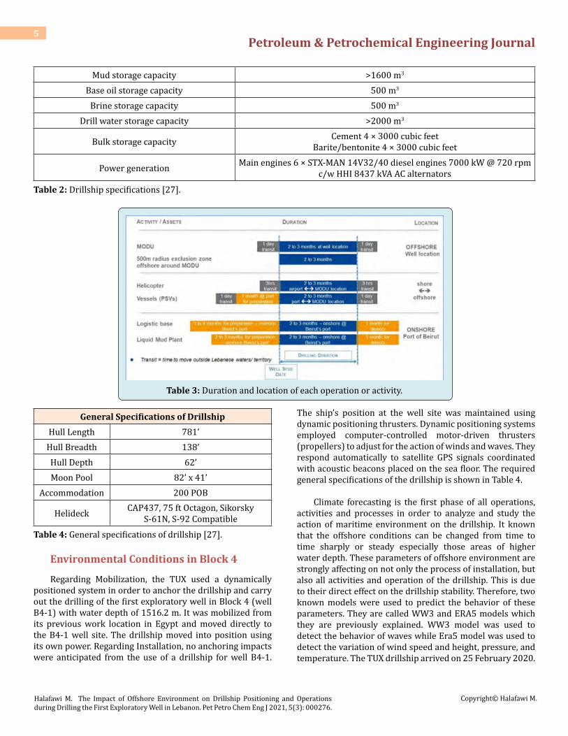
Mud storage capacity >1600 m3
Base oil storage capacity 500 m3
Brine storage capacity 500 m3
Drill water storage capacity >2000 m3
Bulk storage capacity Cement 4 × 3000 cubic feetBarite/bentonite 4 × 3000 cubic feet
Power generation Main engines 6 × STX-MAN 14V32/40 diesel engines 7000 kW @ 720 rpm c/w HHI 8437 kVA AC alternators
Table 2: Drillship specifications [27].
Table 3: Duration and location of each operation or activity.
General Specifications of DrillshipHull Length 781’
Hull Breadth 138’Hull Depth 62’Moon Pool 82’ x 41’
Accommodation 200 POB
Helideck CAP437, 75 ft Octagon, Sikorsky S-61N, S-92 Compatible
Table 4: General specifications of drillship [27].
Environmental Conditions in Block 4
Regarding Mobilization, the TUX used a dynamically positioned system in order to anchor the drillship and carry out the drilling of the first exploratory well in Block 4 (well B4-1) with water depth of 1516.2 m. It was mobilized from its previous work location in Egypt and moved directly to the B4-1 well site. The drillship moved into position using its own power. Regarding Installation, no anchoring impacts were anticipated from the use of a drillship for well B4-1.
The ship’s position at the well site was maintained using dynamic positioning thrusters. Dynamic positioning systems employed computer-controlled motor-driven thrusters (propellers) to adjust for the action of winds and waves. They respond automatically to satellite GPS signals coordinated with acoustic beacons placed on the sea floor. The required general specifications of the drillship is shown in Table 4.
Climate forecasting is the first phase of all operations, activities and processes in order to analyze and study the action of maritime environment on the drillship. It known that the offshore conditions can be changed from time to time sharply or steady especially those areas of higher water depth. These parameters of offshore environment are strongly affecting on not only the process of installation, but also all activities and operation of the drillship. This is due to their direct effect on the drillship stability. Therefore, two known models were used to predict the behavior of these parameters. They are called WW3 and ERA5 models which they are previously explained. WW3 model was used to detect the behavior of waves while Era5 model was used to detect the variation of wind speed and height, pressure, and temperature. The TUX drillship arrived on 25 February 2020.
Petroleum & Petrochemical Engineering Journal 6
Halafawi M. The Impact of Offshore Environment on Drillship Positioning and Operations during Drilling the First Exploratory Well in Lebanon. Pet Petro Chem Eng J 2021, 5(3): 000276.
Copyright© Halafawi M.
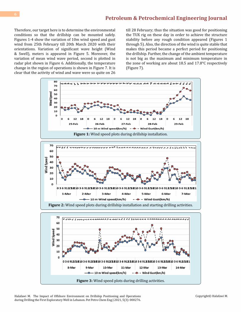
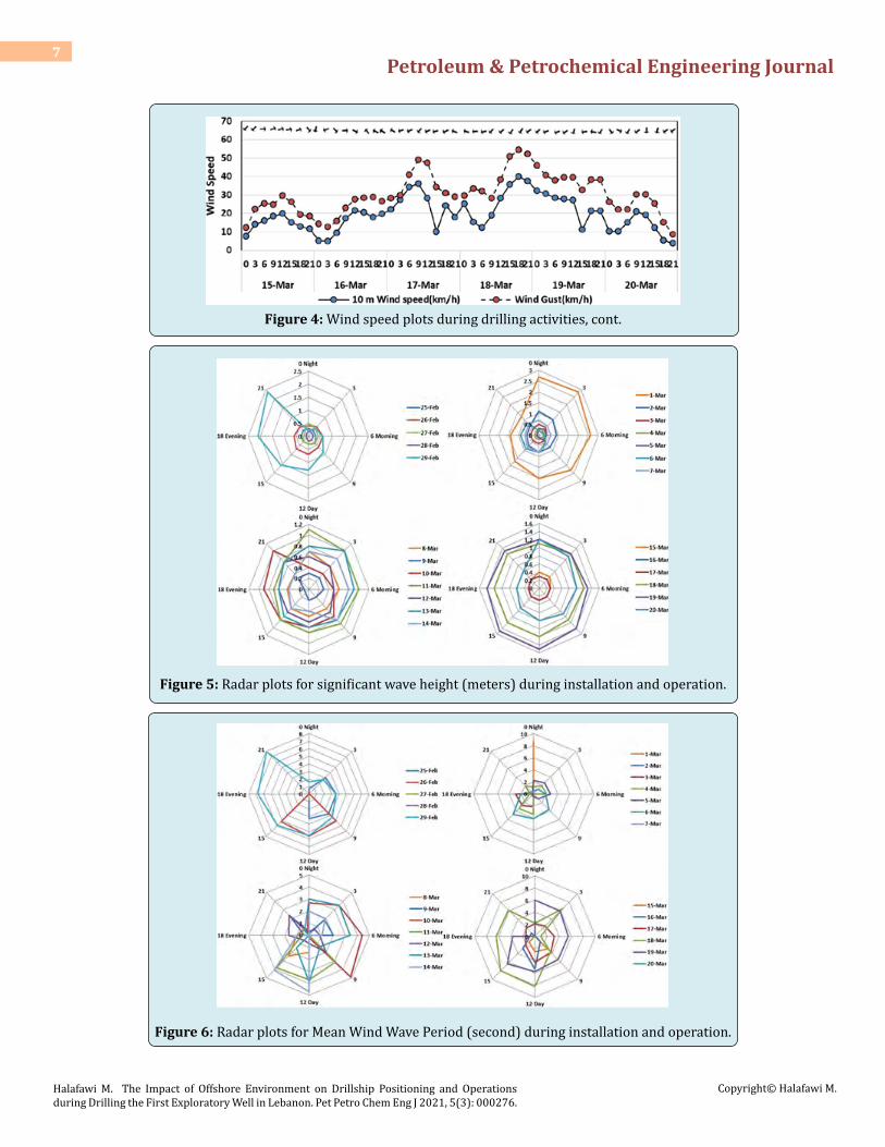
Therefore, our target here is to determine the environmental conditions so that the drillship can be mounted safely. Figures 1-4 show the variation of 10m wind speed and gust wind from 25th February till 20th March 2020 with their orientations. Variation of significant wave height (Wind & Swell), meters is appeared in Figure 5. Moreover, the variation of mean wind wave period, second is plotted in radar plot shown in Figure 6. Additionally, the temperature change in the region of operations is shown in Figure 7. It is clear that the activity of wind and wave were so quite on 26
till 28 February; thus the situation was good for positioning the TUX rig on these day in order to achieve the structure stability before any rough condition appeared (Figures 1 through 5). Also, the direction of the wind is quite stable that makes this period became a perfect period for positioning the drillship. Further, the change of the ambient temperature is not big as the maximum and minimum temperature in the zone of working are about 18.5 and 17.8°C respectively (Figure 7).
Figure 1: Wind speed plots during drillship installation.
Figure 2: Wind speed plots during drillship installation and starting drilling activities.
Figure 3: Wind speed plots during drilling activities.
Petroleum & Petrochemical Engineering Journal 7
Halafawi M. The Impact of Offshore Environment on Drillship Positioning and Operations during Drilling the First Exploratory Well in Lebanon. Pet Petro Chem Eng J 2021, 5(3): 000276.
Copyright© Halafawi M.
Figure 4: Wind speed plots during drilling activities, cont.
Figure 5: Radar plots for significant wave height (meters) during installation and operation.
Figure 6: Radar plots for Mean Wind Wave Period (second) during installation and operation.

Petroleum & Petrochemical Engineering Journal 8
Halafawi M. The Impact of Offshore Environment on Drillship Positioning and Operations during Drilling the First Exploratory Well in Lebanon. Pet Petro Chem Eng J 2021, 5(3): 000276.
Copyright© Halafawi M.
Figure 7: Temperature variation in the area of activities.
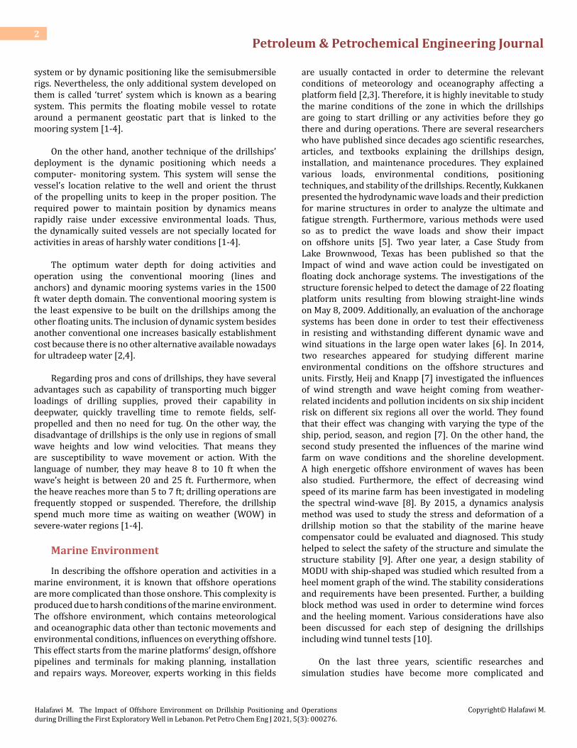
Impacted Loads on Drillship and Derrick
It known that the environmental climate conditions such as wind, wave and current have produced several forces affecting on the offshore structure. The produced forces have a great impact on the structure stability. Here, the structure is derrick installed on the TUX drillship. Therefore, the impacted forces on both the derrick and drillship are determined. Straightforwardly, Hossain and Al-Majed [28] presented a simple equation for computing loads resulting from wind on API derricks. The wind load can be determined as follows [28]:
Fw = 0.004Vw (7)
However, Avram [29] presented the three famous models for calculating the action of marine environment on any offshore structure. These models are function of the wind speed, the shape factor of the structure, and the longitudinal surface area of the structure. Firstly, forces resulting from the
wind energy can be computed according to API methods as follows [29,30]:
20.61 sF C Aν υ= (8)
Secondly, ABS presented a relation for determining the wind forces on any structure as follows [29,30]:
20.623 h sF C C Aν υ= (9)
Lastly, DNV recommended a relationship for calculating the wind forces as follows [29,30]:
( )2 Sin2
F CAν
ρυ α= (10)
Application of the preceded method to our TUX drillship resulted in loads affecting on the derrick and the drillship during the period of positioning and drilling operations as shown in Figures 8-10.
Figure 8: Impact loads on derrick due wind.
Petroleum & Petrochemical Engineering Journal 9
Halafawi M. The Impact of Offshore Environment on Drillship Positioning and Operations during Drilling the First Exploratory Well in Lebanon. Pet Petro Chem Eng J 2021, 5(3): 000276.
Copyright© Halafawi M.
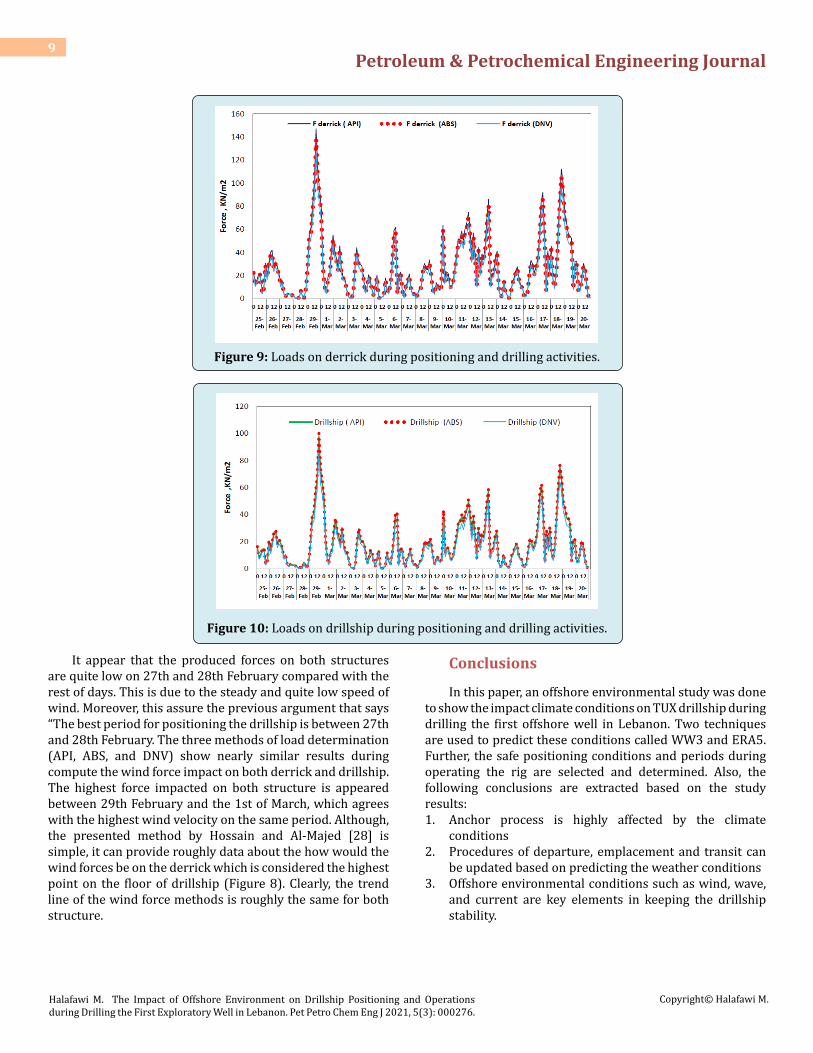
Figure 9: Loads on derrick during positioning and drilling activities.
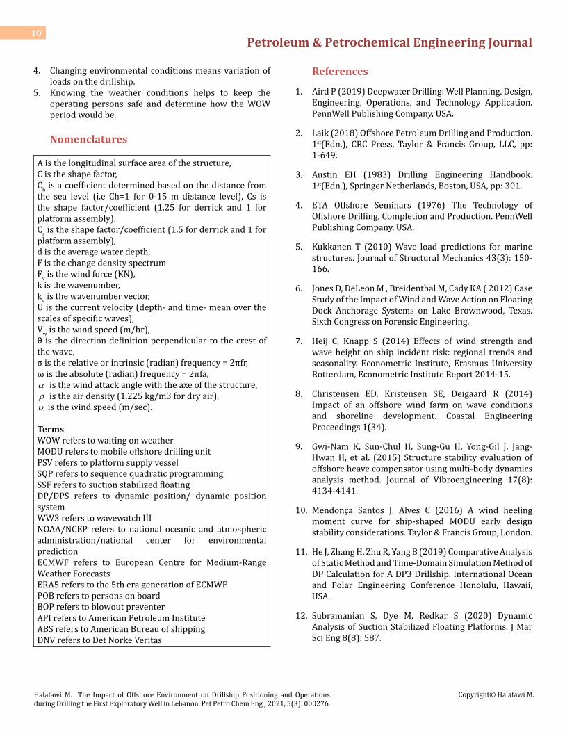
Figure 10: Loads on drillship during positioning and drilling activities.
It appear that the produced forces on both structures are quite low on 27th and 28th February compared with the rest of days. This is due to the steady and quite low speed of wind. Moreover, this assure the previous argument that says “The best period for positioning the drillship is between 27th and 28th February. The three methods of load determination (API, ABS, and DNV) show nearly similar results during compute the wind force impact on both derrick and drillship. The highest force impacted on both structure is appeared between 29th February and the 1st of March, which agrees with the highest wind velocity on the same period. Although, the presented method by Hossain and Al-Majed [28] is simple, it can provide roughly data about the how would the wind forces be on the derrick which is considered the highest point on the floor of drillship (Figure 8). Clearly, the trend line of the wind force methods is roughly the same for both structure.
Conclusions
In this paper, an offshore environmental study was done to show the impact climate conditions on TUX drillship during drilling the first offshore well in Lebanon. Two techniques are used to predict these conditions called WW3 and ERA5. Further, the safe positioning conditions and periods during operating the rig are selected and determined. Also, the following conclusions are extracted based on the study results:1. Anchor process is highly affected by the climate
conditions 2. Procedures of departure, emplacement and transit can
be updated based on predicting the weather conditions 3. Offshore environmental conditions such as wind, wave,
and current are key elements in keeping the drillship stability.
Petroleum & Petrochemical Engineering Journal 10
Halafawi M. The Impact of Offshore Environment on Drillship Positioning and Operations during Drilling the First Exploratory Well in Lebanon. Pet Petro Chem Eng J 2021, 5(3): 000276.
Copyright© Halafawi M.
4. Changing environmental conditions means variation of loads on the drillship.
5. Knowing the weather conditions helps to keep the operating persons safe and determine how the WOW period would be.
Nomenclatures
A is the longitudinal surface area of the structure, C is the shape factor, Ch is a coefficient determined based on the distance from the sea level (i.e Ch=1 for 0-15 m distance level), Cs is the shape factor/coefficient (1.25 for derrick and 1 for platform assembly), Cs is the shape factor/coefficient (1.5 for derrick and 1 for platform assembly), d is the average water depth, F is the change density spectrum Fv is the wind force (KN), k is the wavenumber, kv is the wavenumber vector, U is the current velocity (depth- and time- mean over the scales of specific waves), Vw is the wind speed (m/hr), θ is the direction definition perpendicular to the crest of the wave, σ is the relative or intrinsic (radian) frequency = 2πfr, ω is the absolute (radian) frequency = 2πfa, α is the wind attack angle with the axe of the structure, ρ is the air density (1.225 kg/m3 for dry air), υ is the wind speed (m/sec).
Terms WOW refers to waiting on weather MODU refers to mobile offshore drilling unit PSV refers to platform supply vessel SQP refers to sequence quadratic programming SSF refers to suction stabilized floating DP/DPS refers to dynamic position/ dynamic position system WW3 refers to wavewatch III NOAA/NCEP refers to national oceanic and atmospheric administration/national center for environmental prediction ECMWF refers to European Centre for Medium-Range Weather Forecasts ERA5 refers to the 5th era generation of ECMWF POB refers to persons on board BOP refers to blowout preventer API refers to American Petroleum Institute ABS refers to American Bureau of shipping DNV refers to Det Norke Veritas
References
1. Aird P (2019) Deepwater Drilling: Well Planning, Design, Engineering, Operations, and Technology Application. PennWell Publishing Company, USA.
2. Laik (2018) Offshore Petroleum Drilling and Production. 1st(Edn.), CRC Press, Taylor & Francis Group, LLC, pp: 1-649.
3. Austin EH (1983) Drilling Engineering Handbook. 1st(Edn.), Springer Netherlands, Boston, USA, pp: 301.
4. ETA Offshore Seminars (1976) The Technology of Offshore Drilling, Completion and Production. PennWell Publishing Company, USA.
5. Kukkanen T (2010) Wave load predictions for marine structures. Journal of Structural Mechanics 43(3): 150-166.
6. Jones D, DeLeon M , Breidenthal M, Cady KA ( 2012) Case Study of the Impact of Wind and Wave Action on Floating Dock Anchorage Systems on Lake Brownwood, Texas. Sixth Congress on Forensic Engineering.
7. Heij C, Knapp S (2014) Effects of wind strength and wave height on ship incident risk: regional trends and seasonality. Econometric Institute, Erasmus University Rotterdam, Econometric Institute Report 2014-15.
8. Christensen ED, Kristensen SE, Deigaard R (2014) Impact of an offshore wind farm on wave conditions and shoreline development. Coastal Engineering Proceedings 1(34).
9. Gwi-Nam K, Sun-Chul H, Sung-Gu H, Yong-Gil J, Jang-Hwan H, et al. (2015) Structure stability evaluation of offshore heave compensator using multi-body dynamics analysis method. Journal of Vibroengineering 17(8): 4134-4141.
10. Mendonça Santos J, Alves C (2016) A wind heeling moment curve for ship-shaped MODU early design stability considerations. Taylor & Francis Group, London.
11. He J, Zhang H, Zhu R, Yang B (2019) Comparative Analysis of Static Method and Time-Domain Simulation Method of DP Calculation for A DP3 Drillship. International Ocean and Polar Engineering Conference Honolulu, Hawaii, USA.
12. Subramanian S, Dye M, Redkar S (2020) Dynamic Analysis of Suction Stabilized Floating Platforms. J Mar Sci Eng 8(8): 587.

Petroleum & Petrochemical Engineering Journal 11
Halafawi M. The Impact of Offshore Environment on Drillship Positioning and Operations during Drilling the First Exploratory Well in Lebanon. Pet Petro Chem Eng J 2021, 5(3): 000276.
Copyright© Halafawi M.
13. Sutulo S, Guedes Soares C (2021) Review on Ship Manoeuvrability Criteria and Standards. J Mar Sci Eng 9(8): 904.
14. The WAVEWATCH III Development Group (WW3DG), (2019) User manual and system documentation of WAVEWATCH III R version 6.07. Tech. Note 333, NOAA/NWS/NCEP/MMAB, College Park, MD, USA, pp: 465.
15. Halafawi M, Mhanna A, Avram L (2019) The Impact of Marine Environment on Jackup Rig Stability. Pet Petro Chem Eng J 4(5): 1-16.
16. Komen GJ, Cavaleri L, Donelan M, Hasselmann K, Hasselmann S, et al. (1994) Dynamics and modelling of ocean waves. Cambridge University Press, UK, pp: 532.
17. Tolman HL (1990) The influence of unsteady depths and currents of tides on wind wave propagation in shelf seas. J Phys Oceanogr 20(1): 1166-1174.
18. Tolman HL (1991) A third-generation model for wind waves on slowly varying, unsteady and inhomogeneous depths and currents. J Phys Oceanogr 21(6): 782-797.
19. Benassai G, Ascione I (2016) Implementation of WWIII wave model for the study of risk inundation on the coastlines of Campania, Italy. WIT Transactions on Ecology and the Environment 88(11).
20. Christoffersen JB (1982) Current depth refraction of dissipative water waves. Series Paper 30, Institute of Hydrodynamics and Hydraulic Engineering, Technical University, Denmark.
21. Mei CC (1983) The applied dynamics of ocean surface
waves. Wiley, New York, pp: 740.
22. Phillips OM (1977) The dynamics of the upper ocean. 2nd (Edn.), Cambridge University Press, UK, pp: 336.
23. Copernicus Climate Change Service (C3S) ERA5: Fifth Generation of ECMWF Atmospheric Reanalyses of the Global Climate.
24. Hoffmann L, Günther G, Li D, Stein O, Wu X, et al. (2019) From ERA-Interim to ERA5: The considerable impact of ECMWF’s next-generation reanalysis on Lagrangian transport simulations. Atmos Chem Phys 19(5): 3097-3124.
25. Mateus P, Mendes VB, Plecha SM (2021) HGPT2: An ERA5-Based Global Model to Estimate Relative Humidity. Remote Sens 13(11): 2179.
26. Hersbach H, Bell B, Berrisford P, Hirahara S, Horányi A, et al. (2020) The ERA5 global reanalysis. Q J R Meteorol Soc 146(730): 1999-2049.
27. Tungsten Explorer Short Specification (2020) Tungsten Explorer 6th Generation Ultra Deepwater Drillship. Vantage Drilling International Co.
28. Hossain ME, Al-Majed AA (2015) Fundamentals of Sustainable Drilling Engineering. John Wiley & Sons, pp: 786.
29. Avram L (2005) Foraj marin. Editura Universităţii Petrol-Gaze din Ploieşti, pp: 211.
30. Iordache G, Avram L (1998) Foraje speciale şi foraj marin. Editura Tehnică, Bucureşti, pp: 236.