Embed Size (px)
Citation preview
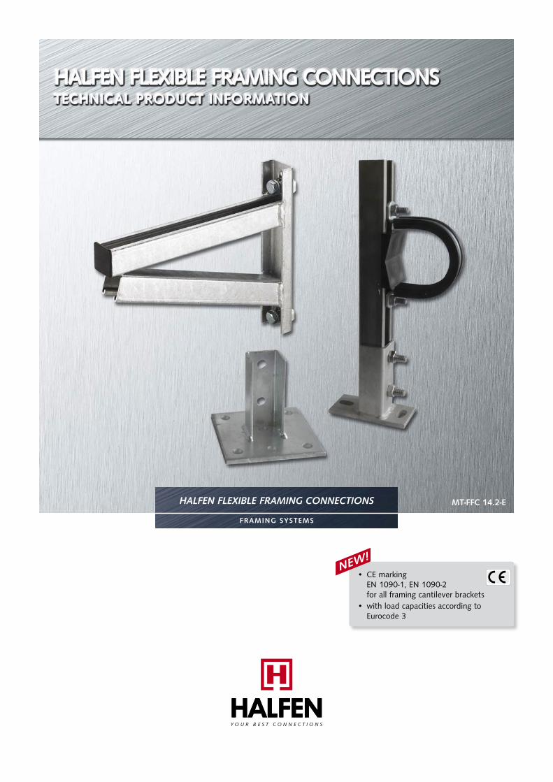
HALFEN FLEXIBLE FRAMING CONNECTIONS
FRAMING SYSTEMS
MT-FFC 14.2-E
• CE marking EN 1090-1, EN 1090-2
for all framing cantilever brackets • with load capacities according to Eurocode 3
NEW!
2 © 2017 HALFEN · MT-FFC 14.2-E · www.halfen.com
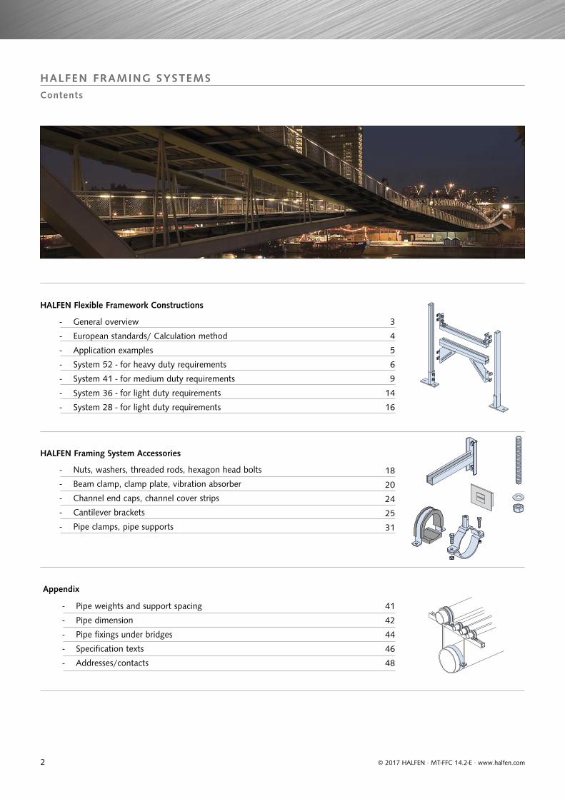
HALFEN FRAMING SYSTEMSContents
HALFEN Flexible Framework Constructions
3
4
5
6
9
14
16
HALFEN Framing System Accessories
- Nuts, washers, threaded rods, hexagon head bolts
- Beam clamp, clamp plate, vibration absorber
- Channel end caps, channel cover strips
- Cantilever brackets
- Pipe clamps, pipe supports
18
20
24
25
31
Appendix
- Pipe weights and support spacing
- Pipe dimension
- Pipe fixings under bridges
- Specification texts
- Addresses/contacts
41
42
44
46
48
- General overview
- European standards/ Calculation method
- Application examples
- System 52 - for heavy duty requirements
- System 41 - for medium duty requirements
- System 36 - for light duty requirements
- System 28 - for light duty requirements
3© 2017 HALFEN · MT-FFC 14.2-E · www.halfen.com
HALFEN FRAMING SYSTEMSGeneral Overview
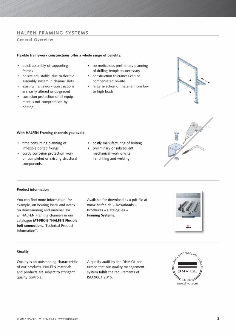
Flexible framework constructions offer a whole range of benefits:
With HALFEN Framing channels you avoid:
Quality is an outstanding characteristic of our products. HALFEN materials and products are subject to stringent quality controls.
Quality
Product information
A quality audit by the DNV GL con-firmed that our quality management system fulfils the requirements of ISO 9001:2015.
You can find more information, for example, on bearing loads and notes on dimensioning and material, for all HALFEN Framing channels in our catalogue MT-FBC-E “HALFEN Flexible bolt connections, Technical Product Information”.
• quick assembly of supportingframes
• on-site adjustable, due to flexible assembly system in channel slots
• existing framework constructions are easily altered or up-graded
• corrosion protection of all equip-ment is not compromised by bolting
• time consuming planning of inflexible bolted fixings
• costly corrosion protection work on completed or existing structural components
• costly manufacturing of bolting• preliminary or subsequent
mechanical work on-site i.e. drilling and welding
• no meticulous preliminary planning of drilling templates necessary
• construction tolerances can be compensated on-site
• large selection of material from low to high loads
Available for download as a pdf file at www.halfen.de – Downloads – Brochures – Catalogues – Framing Systems.
HALFEN FLEXIBLE BOLT CONNECTIONS
FRAMING SYSTEMS
MT-FBC 10.1-E
www.dnvgl.com
4
EN 1090-1, EN 1090-22499 – CPR-0113070-00-01
© 2017 HALFEN · MT-FFC 14.2-E · www.halfen.com
HALFEN FRAMING SYSTEMSGeneral Overview
European standards EN 1090 / EN 1993
The new EN 1090 series of standards replace the previous DIN 18800-7 Standard, regulating execution of steel structures and manufacturing qualifica-tions. European standard EN 1090-1 specifies requirements for conformity assessment (CE marking) of structural components which will be placed on the European market as construction products.The conformity assessment covers production characteristics and where appropriate, the structural design characteristics. The EN 1090-2 Standard regulates the requirements applicable to the execu-tion of steel structures. This standard applies to structures that are verified according to the appropriate section of EN 1993 (EC3).
The phase-out period for DIN 18800-7ended on the 30th of June 2014. Basis for the evaluation of conformity of steel construction products is the system of assessment of conformity 2+ according to Construction Products Regulation (CPR) EU No. 305/2011.
The European standard EN 1993 was created with the intention to establish uniform, Europe-wide calculation methods for steel structures. However, because these calculation methods have not yet been adopted in all industries we have decided to include two sets of values for cantilever load capacities in the following tables.
The traditional, deterministic safety concept however, is based on the method of using a global safety factor for material resistance and is known as the “allowable load method“ or “allowable tension method“. These methods are used in mechanical and apparatus engineering. In these cases the allowable values for load capacity are calculated. Verification is as follows:
The term “design value” is taken from the current applicable standards, for example EN 1993 (EC3), with new safety concept, and must be strictly differentiated from the term “allowable load”. The European standard which is based on the so called “partial safety factors” is applied to material resistanceas well as to the action (load). The following verification is required:
F = load on the structureallow. F = allowable load
The CE marking confirms conformity
with the declared performance of
HALFEN Products and with all relevant
European harmonized standards in the
European Union.
HALFEN Framing channels are also
subject to these regulations. To meet CE evaluation obligations the marked products are statically verified in accordance with EN 1993 and the principal performance characteristics are detailed in the respective Declara-tion of Performance, CONF-DOP_KON.CE marking is mandatory from the 1st
of July 2014 when distributing load bearing metallic construction products in the European market.HALFEN is certified by the notified Body ZDH-ZERT GmbH. Apart from production, the certification includes the method of calculation required by the HALFEN Engineers and their respective qualifications.
FEd ≤ FRd
F ≤ allow. F
Design method
• working loads will continue to be defined as “allow. F“ and
• design values of the resistance will be defined as „FRd“.
FEd = calculation value for actionFRd = design value for resistance
5© 2017 HALFEN · MT-FFC 14.2-E · www.halfen.com
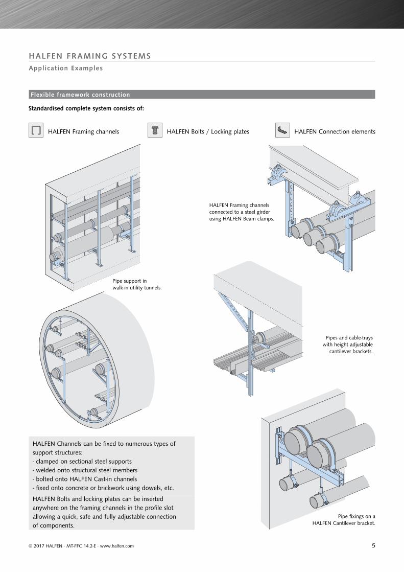
HALFEN FRAMING SYSTEMSApplication Examples
Standardised complete system consists of:
HALFEN Framing channels HALFEN Bolts / Locking plates
HALFEN Framing channels connected to a steel girder using HALFEN Beam clamps.
Pipe support in walk-in utility tunnels.
Pipes and cable-trays with height adjustable
cantilever brackets.
Pipe fixings on a HALFEN Cantilever bracket.
HALFEN Connection elements
HALFEN Channels can be fixed to numerous types of support structures:- clamped on sectional steel supports- welded onto structural steel members- bolted onto HALFEN Cast-in channels- fixed onto concrete or brickwork using dowels, etc.
HALFEN Bolts and locking plates can be inserted anywhere on the framing channels in the profile slot allowing a quick, safe and fully adjustable connection of components.
Flexible framework construction
6
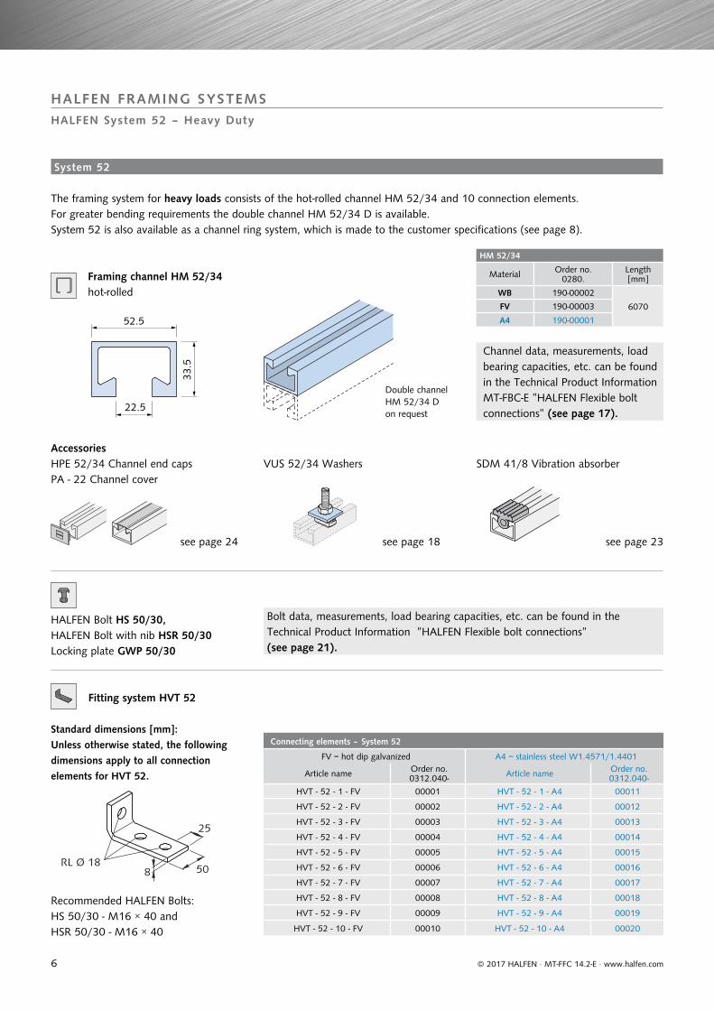
HM 52/34
Material Order no.0280.
Length[mm]
WB 190-00002
6070FV 190-00003
A4 190-00001
Connecting elements – System 52
FV = hot dip galvanized A4 = stainless steel W1.4571/1.4401
Article name Order no.0312.040- Article name Order no.
0312.040-
HVT - 52 - 1 - FV 00001 HVT - 52 - 1 - A4 00011
HVT - 52 - 2 - FV 00002 HVT - 52 - 2 - A4 00012
HVT - 52 - 3 - FV 00003 HVT - 52 - 3 - A4 00013
HVT - 52 - 4 - FV 00004 HVT - 52 - 4 - A4 00014
HVT - 52 - 5 - FV 00005 HVT - 52 - 5 - A4 00015
HVT - 52 - 6 - FV 00006 HVT - 52 - 6 - A4 00016
HVT - 52 - 7 - FV 00007 HVT - 52 - 7 - A4 00017
HVT - 52 - 8 - FV 00008 HVT - 52 - 8 - A4 00018
HVT - 52 - 9 - FV 00009 HVT - 52 - 9 - A4 00019
HVT - 52 - 10 - FV 00010 HVT - 52 - 10 - A4 00020
25
8 50RL Ø 18
© 2017 HALFEN · MT-FFC 14.2-E · www.halfen.com
HALFEN FRAMING SYSTEMSHALFEN System 52 – Heavy Duty
see page 24
HPE 52/34 Channel end caps PA - 22 Channel cover
Double channel HM 52/34 D on request
Channel data, measurements, load bearing capacities, etc. can be found in the Technical Product Information MT-FBC-E ”HALFEN Flexible bolt connections” (see page 17).
Bolt data, measurements, load bearing capacities, etc. can be found in the Technical Product Information ”HALFEN Flexible bolt connections” (see page 21).
AccessoriesVUS 52/34 Washers SDM 41/8 Vibration absorber
The framing system for heavy loads consists of the hot-rolled channel HM 52/34 and 10 connection elements. For greater bending requirements the double channel HM 52/34 D is available. System 52 is also available as a channel ring system, which is made to the customer specifications (see page 8).
see page 18 see page 23
Framing channel HM 52/34
HALFEN Bolt HS 50/30, HALFEN Bolt with nib HSR 50/30 Locking plate GWP 50/30
Fitting system HVT 52
Standard dimensions [mm]:Unless otherwise stated, the following dimensions apply to all connection elements for HVT 52.
Recommended HALFEN Bolts:HS 50/30 - M16 × 40 and HSR 50/30 - M16 × 40
hot-rolled
System 52
52.5
22.5
33.5
7
147
190
60
120
50
10060
1905
172
54
180180
5
135
25
60
125
75
5
75
180135
5
4
200
2005
230
60
805
HVT 52-8
© 2017 HALFEN · MT-FFC 14.2-E · www.halfen.com
HALFEN FRAMING SYSTEMSHALFEN System 52 – Heavy Duty
HVT 52-1
HVT 52-6
HVT 52-2
HVT 52-7
HVT 52-3
HVT 52-8
HVT 52-4 HVT 52-5
HVT 52-9 HVT 52-10
Assembly note for fitting system HVT 52-8
Two HVT 52/8 elements inone connection
Channel slot on one level
Because of their unique shape two HVT 52-8 elements can be installed directly adjacent to each other when used for channel-cross connections on the same level.
Example: Support foot
Application examples
Note: Each detail shows only one of many possible applications.
8
HM 52/34
HVT 52-2
HM 52/34D
HVT 52/8
HVT 52/7
HM 52/34
HVT 52-7
HVT 52-6
HM 52/34
HM 52/34
© 2017 HALFEN · MT-FFC 14.2-E · www.halfen.com
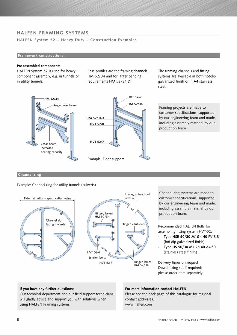
HALFEN FRAMING SYSTEMSHALFEN System 52 – Heavy Duty – Construction Examples
Pre-assembled components
Example: Channel ring for utility tunnels (culverts)
Delivery times on request. Dowel fixing set if required; please order item separately.
If you have any further questions: Our technical department and our field support technicians will gladly advise and support you with solutions when using HALFEN Framing systems.
Example: Floor support
HALFEN System 52 is used for heavy component assembly, e.g. in tunnels or in utility tunnels.
Base profiles are the framing channels HM 52/34 and for larger bending requirements HM 52/34 D.
The framing channels and fitting systems are available in both hot-dip galvanized finish or in A4 stainless steel.
Recommended HALFEN Bolts for assembling fitting system HVT-52: - Type HSR 50/30 M16 × 40 FV 8.8 (hot-dip galvanized finish)- Type HS 50/30 M16 × 40 A4-50 (stainless steel finish)
Framing projects are made to customer specifications, supported by our engineering team and made, including assembly material by our production team.
Channel ring systems are made to customer specifications, supported by our engineering team and made, including assembly material by our production team.
Angle cross beam
Cross beam, increased bearing capacity
Hinged cantilever
Hinged beam
Hexagon head bolt with nut
tension bolts
Channel ring
Channel slot facing inwards
External radius = specification value
Framework constructions
For more information contact HALFENPlease see the back page of this catalogue for regionalcontact addresses.www.halfen.com
Hinged brace
9
HM 41/41 and HL 41/41
Material Order no. Length [mm]
HM 41/41 0280.
6000
WB 080-00001
SV 080-00002
FV 080-00003
A4 080-00004
HL 41/41 0281.
WB 010-00001
SV 010-00003
FV 010-00002
A4 010-00004
HM 41/41 D 0280.
WB 150-00001
FV 150-00003
A4 150-00002
HZM 41/41 and HZL 41/41
Material Order no. Length [mm]
HZM 41/41 0284.
6000
WB 010-00001
FV 010-00002
A4 010-00003
HZL 41/41 0283.
WB 010-00001
FV 010-00002
A4 010-00003
HZM 41/41 D 0284.
WB 030-00001
FV 030-00002
A4 030-00003
HM 41/22 and HL 41/22
Material Order no. Length [mm]
HM 41/22 0280.
6000
WB 120-00001
SV 120-00002
FV 120-00003
A4 120-00004
HL 41/22 0281.
WB 020-00001
SV 020-00003
FV 020-00002
A4 020-00004
HM 41/22 D 0280.
WB 160-00001
FV 160-00002
A4 160-00003
HL 41/41
14
2850
41
41
22
41
41
22
41
21
22
14
28
50
HZL 41/22
HZL 41/41
14
28
50
© 2017 HALFEN · MT-FFC 14.2-E · www.halfen.com
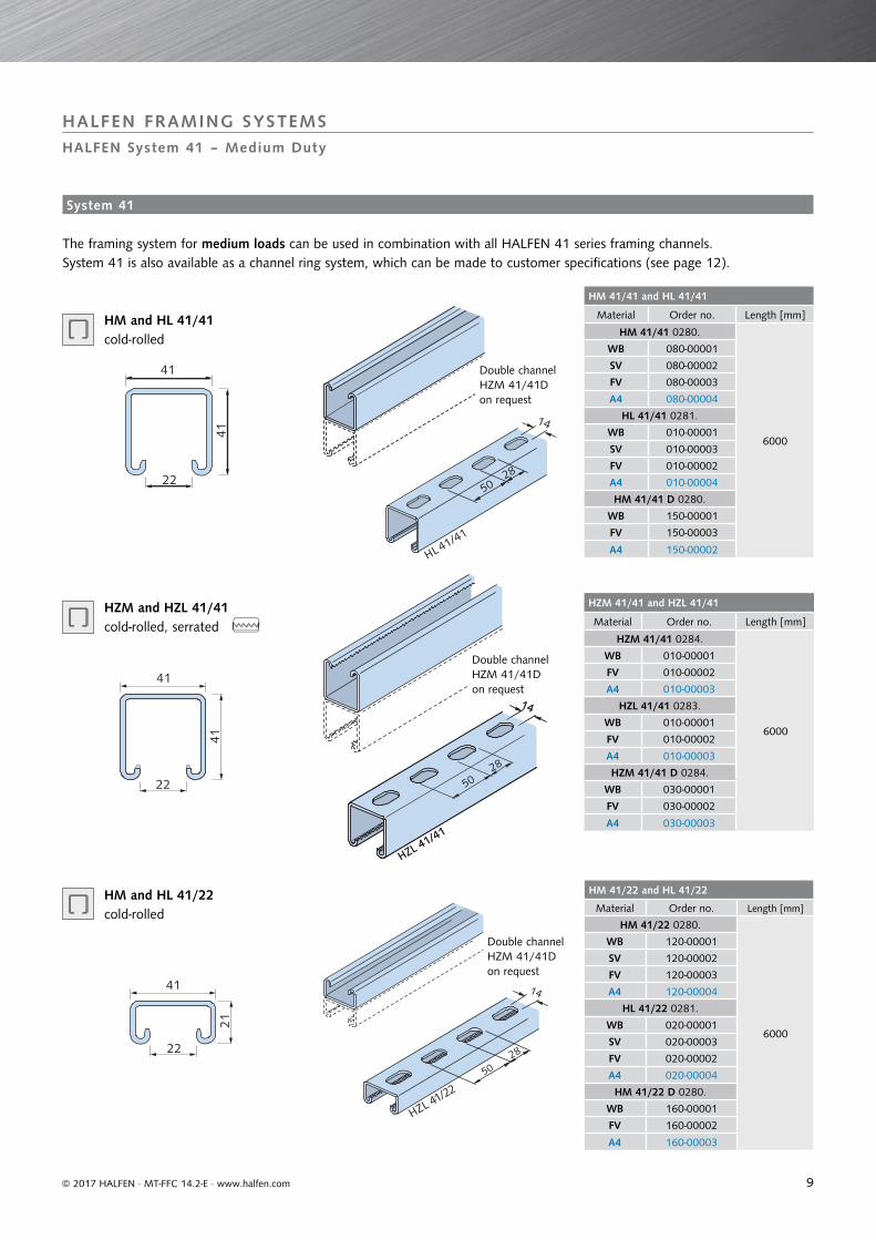
HALFEN FRAMING SYSTEMSHALFEN System 41 – Medium Duty
HM and HL 41/41 cold-rolled
Double channel HZM 41/41Don request
Double channel HZM 41/41Don request
Double channel HZM 41/41Don request
HZM and HZL 41/41 cold-rolled, serrated
The framing system for medium loads can be used in combination with all HALFEN 41 series framing channels.System 41 is also available as a channel ring system, which can be made to customer specifications (see page 12).
HM and HL 41/22 cold-rolled
HZL 41/41
14
28
50
System 41
10
HZM 41/22 and HZL 41/22
Material Order no. Length[mm]
HZM 41/22 0284.
6070WB 020-00001
FV 020-00002
A4 020-00003
HZL 41/22 0283.
6000WB 020-00001
FV 020-00002
A4 020-00003
HZM 41/22 D 0284.
6070WB 040-00001
FV 040-00002
A4 040-00003
41
21
22
14
28
50
HZL 41/22
4820
406RL Ø 14
© 2017 HALFEN · MT-FFC 14.2-E · www.halfen.com
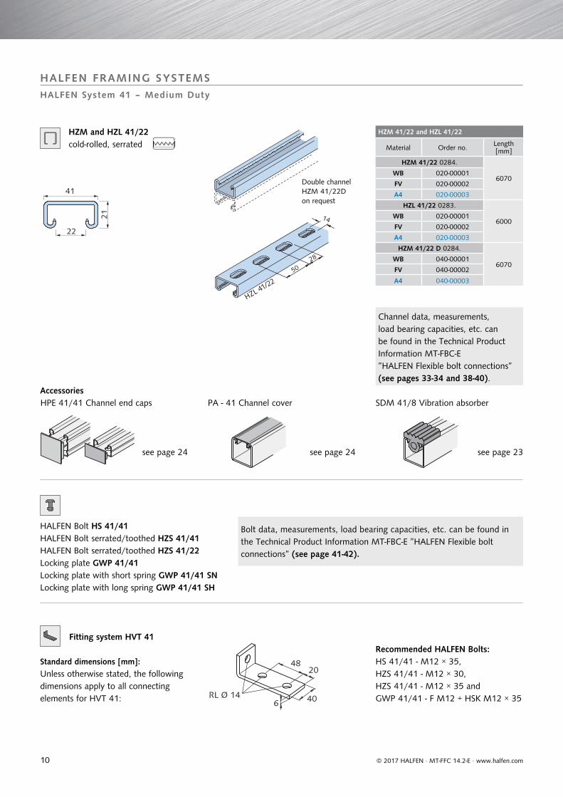
HALFEN FRAMING SYSTEMSHALFEN System 41 – Medium Duty
HZM and HZL 41/22 cold-rolled, serrated
see page 24 see page 24 see page 23
HPE 41/41 Channel end caps PA - 41 Channel cover SDM 41/8 Vibration absorber
HALFEN Bolt HS 41/41 HALFEN Bolt serrated/toothed HZS 41/41HALFEN Bolt serrated/toothed HZS 41/22Locking plate GWP 41/41Locking plate with short spring GWP 41/41 SNLocking plate with long spring GWP 41/41 SH
Accessories
Channel data, measurements, load bearing capacities, etc. can be found in the Technical Product Information MT-FBC-E ”HALFEN Flexible bolt connections” (see pages 33-34 and 38-40).
Bolt data, measurements, load bearing capacities, etc. can be found in the Technical Product Information MT-FBC-E ”HALFEN Flexible bolt connections” (see page 41-42).
Double channel HZM 41/22D on request
Fitting system HVT 41
Standard dimensions [mm]:Unless otherwise stated, the following dimensions apply to all connecting elements for HVT 41:
Recommended HALFEN Bolts:HS 41/41 - M12 × 35, HZS 41/41 - M12 × 30,HZS 41/41 - M12 × 35 andGWP 41/41 - F M12 + HSK M12 × 35
11
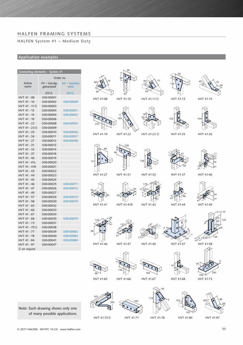
Connecting elements – System 41
Articlename
Order no.
FV = hot-dip galvanized
0312.
A4 = stainless steel
0312.HVT 41 - 08 030-00001 HVT 41 - 10 030-00002 030-00049HVT 41 - 11 030-00003 HVT 41 - 13 030-00004 030-00051HVT 41 - 15 030-00005 030-00052HVT 41 - 19 030-00006 HVT 41 - 22 030-00008 030-00054HVT 41 - 23 030-00009 HVT 41 - 25 030-00010 030-00056 HVT 41 - 26 030-00011 030-00057HVT 41 - 27 030-00012 030-00058HVT 41 - 31 030-00013 HVT 41 - 33 030-00014 HVT 41 - 37 030-00018 HVT 41 - 40 030-00019 HVT 41 - 41L 030-00020 HVT 41 - 41R 030-00021 HVT 41 - 43 030-00022 HVT 41 - 44 030-00023 HVT 41 - 45 030-00024 HVT 41 - 46 030-00025 030-00071HVT 41 - 47 030-00026 030-00072HVT 41 - 49 030-00027 HVT 41 - 57 030-00029 030-00074HVT 41 - 58 030-00030 030-00075HVT 41 - 65 030-00032 HVT 41 - 66 030-00033 HVT 41 - 67 030-00034 HVT 41 - 68 030-00035 030-00079HVT 41 - 73 030-00037 HVT 41 - 75 030-00038 HVT 41 - 77 030-00039 030-00082HVT 41 - 78 030-00040 030-00083HVT 41 - 84 030-00041 030-00084HVT 41 - 97 030-00047 on request
79 60°
64 42
90
90
77
64
45°136
90
58 76 45°
232
164 50 50
89
104
41
104
47 98
137
42
90
138
138
51 21
41 54
41
50
50 50
50
47
178
96 96
47
47 43
83
41
54
41
137 38
47
98
137
41
47 41
21 100
ø 14
100
4060
812
0
140
4
135
65
8
120 206040
2 x ø 14
LL 13x26
88 136
184 41
57 40
100
5
200
197
200 184
5
115
50
4
70
102
102
60°48
86
© 2017 HALFEN · MT-FFC 14.2-E · www.halfen.com
HALFEN FRAMING SYSTEMSHALFEN System 41 – Medium Duty
HVT 41-08
HVT 41-19
HVT 41-27 HVT 41-37
HVT 41-45
HVT 41-58
HVT 41-75
HVT 41-10
HVT 41-22
HVT 41-31 HVT 41-40
HVT 41-46
HVT 41-65
HVT 41-77
HVT 41-11
HVT 41-23
HVT 41-33
HVT 41-41
HVT 41-47
HVT 41-66
HVT 41-78
HVT 41-13
HVT 41-25
HVT 41-41R
HVT 41-49
HVT 41-67
HVT 41-84
HVT 41-15
HVT 41-26
HVT 41-43
HVT 41-57
HVT 41-68
HVT 41-97
HVT 41-73
HVT 41-44
Note: Each drawing shows only one of many possible applications.
Application examples
12
Article name and order no.
Material: FV = hot-dip galvanized Order no. 0304.
HCS - 41 - SRI - P - FV Radius Ra 010-00002
HCS - 41 - SRI - M - FV 020-00002
Material: A4 = stainless steel
HCS - 41 - SRI - P - A4 Radius Ra 010-00001
HCS - 41 - SRI - M - A4 020-00002
Always specify external radius Ra [mm] when ordering
R a
© 2017 HALFEN · MT-FFC 14.2-E · www.halfen.com
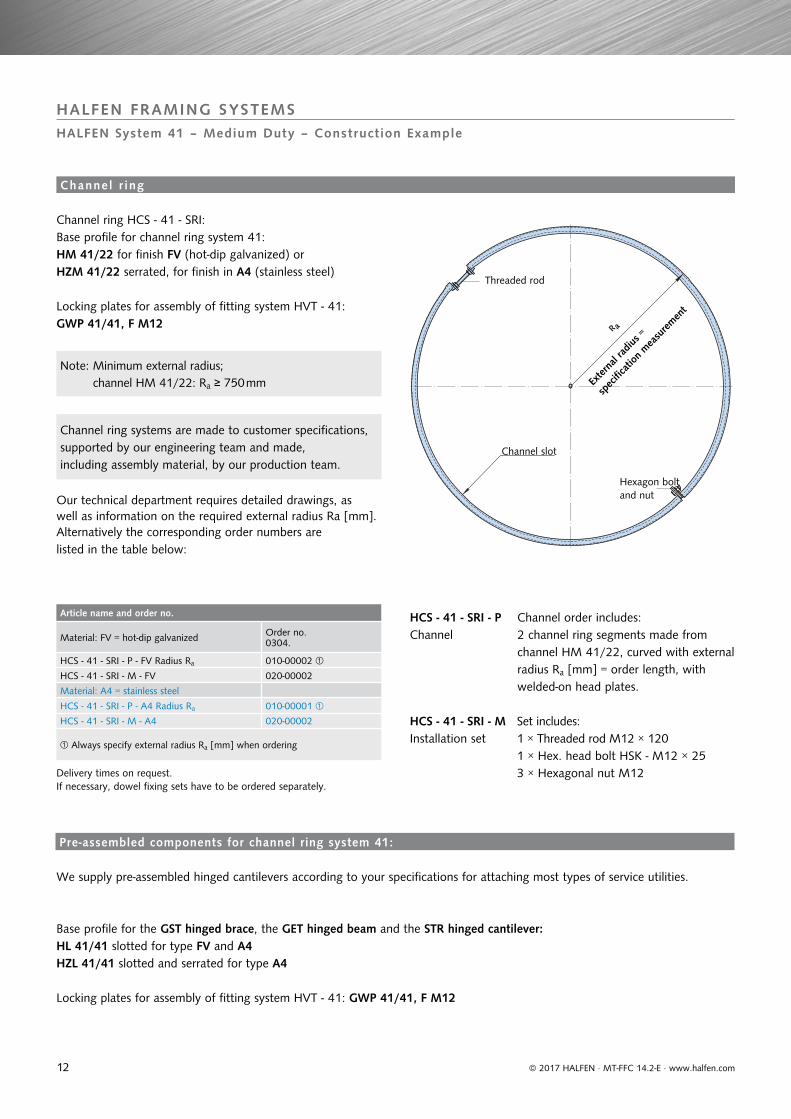
HALFEN FRAMING SYSTEMSHALFEN System 41 – Medium Duty – Construction Example
Channel order includes:2 channel ring segments made from channel HM 41/22, curved with external radius Ra [mm] = order length, with welded-on head plates.
HCS - 41 - SRI - PChannel
HCS - 41 - SRI - MInstallation set
Set includes:1 × Threaded rod M12 × 1201 × Hex. head bolt HSK - M12 × 253 × Hexagonal nut M12
Channel ring HCS - 41 - SRI:Base profile for channel ring system 41:HM 41/22 for finish FV (hot-dip galvanized) orHZM 41/22 serrated, for finish in A4 (stainless steel)
Locking plates for assembly of fitting system HVT - 41:GWP 41/41, F M12
Locking plates for assembly of fitting system HVT - 41: GWP 41/41, F M12
Channel r ing
HL 41/41 slotted for type FV and A4HZL 41/41 slotted and serrated for type A4
Channel ring systems are made to customer specifications, supported by our engineering team and made, including assembly material, by our production team.
Delivery times on request.If necessary, dowel fixing sets have to be ordered separately.
Base profile for the GST hinged brace, the GET hinged beam and the STR hinged cantilever:
We supply pre-assembled hinged cantilevers according to your specifications for attaching most types of service utilities.
Channel slot
Threaded rod
Hexagon bolt and nut
Exter
nal r
adius
=
spec
ificati
on m
easu
remen
t
Pre-assembled components for channel ring system 41:
Our technical department requires detailed drawings, as well as information on the required external radius Ra [mm].Alternatively the corresponding order numbers arelisted in the table below:
Note: Minimum external radius; channel HM 41/22: Ra ≥ 750 mm
13
Article name and order no.
Material: FV - hot-dip galvanized Order no.0304.
HCS - 41 - GST - P - FV Length LB 060-00002
HCS - 41 - GST - M - FV 070-00002
Material: A4 = stainless steel
HCS - 41 - GST - P - A4 Length LB 060-00001
HCS - 41 - GST - M - A4 070-00002
State length LB [mm] when ordering
Article name and order no.
Material: FV - hot-dip galvanized Order no.0304.
HCS - 41 - GET - P - FV Length LB 050-00002
HCS - 41 - GET - M - FV 040-00002
Material: A4 = stainless steel
HCS - 41 - GET - P - A4 Length LB 050-00001
HCS - 41 - GET - M - A4 040-00002
State length LB [mm] when ordering
Article name and order no.
Material: FV - hot-dip galvanized Order no.0304.
HCS - 41 - STR - P - FV Length LB 080-00002
HCS - 41 - STR - M - FV 090-00002
Material: A4 = stainless steel
HCS - 41 - STR - P - A4 Length LB 080-00001
HCS - 41 - STR - M - A4 090-00002
State length LB [mm] when ordering
- SRI
- STR
- GST
- GST
- GET
- GET
8
20
33
5050
20
20
50
5020
© 2017 HALFEN · MT-FFC 14.2-E · www.halfen.com
HALFEN FRAMING SYSTEMSHALFEN System 41 – Medium Duty – Construction Example
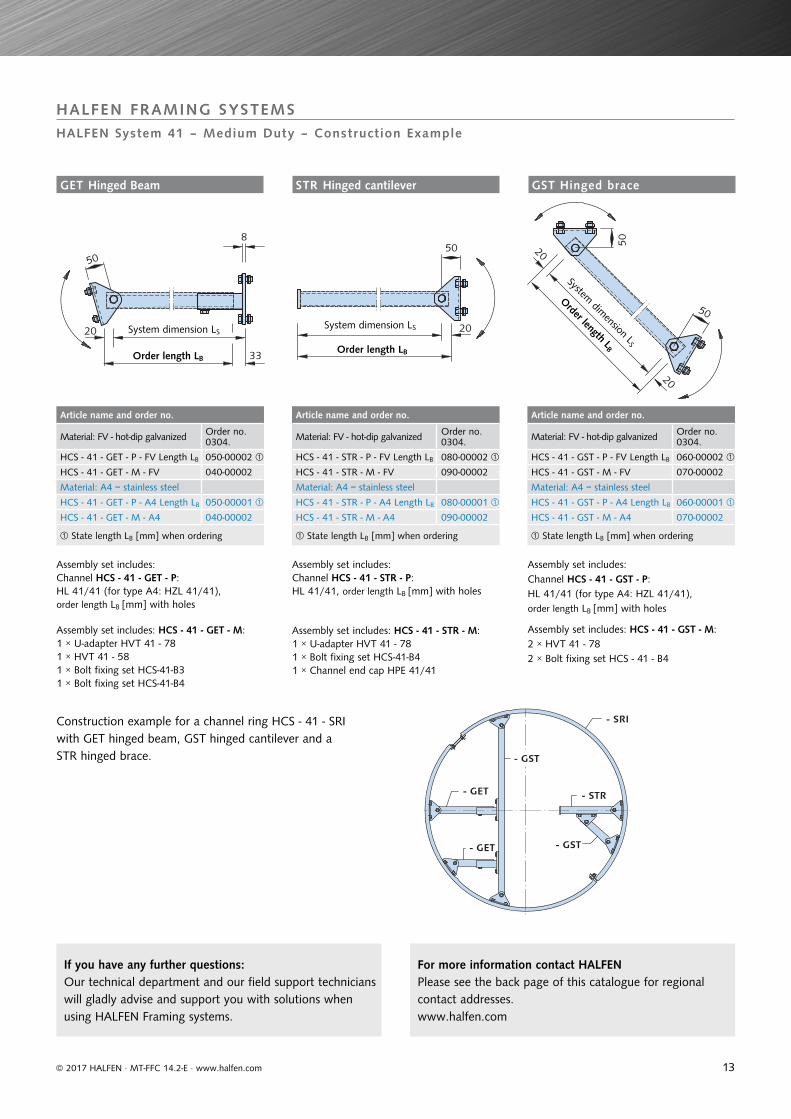
Assembly set includes: Channel HCS - 41 - GST - P: HL 41/41 (for type A4: HZL 41/41), order length LB [mm] with holes
Assembly set includes: Channel HCS - 41 - GET - P:HL 41/41 (for type A4: HZL 41/41), order length LB [mm] with holes
Assembly set includes: Channel HCS - 41 - STR - P: HL 41/41, order length LB [mm] with holes
Assembly set includes: HCS - 41 - GET - M:1 × U-adapter HVT 41 - 781 × HVT 41 - 581 × Bolt fixing set HCS-41-B31 × Bolt fixing set HCS-41-B4
Assembly set includes: HCS - 41 - STR - M:1 × U-adapter HVT 41 - 781 × Bolt fixing set HCS-41-B41 × Channel end cap HPE 41/41
Assembly set includes: HCS - 41 - GST - M:2 × HVT 41 - 782 × Bolt fixing set HCS - 41 - B4
Construction example for a channel ring HCS - 41 - SRI with GET hinged beam, GST hinged cantilever and a STR hinged brace.
System dimension LS
Order length LB
System dimension LS
Order length LB
System dimension LS
Order length LB
GET Hinged Beam STR Hinged cantilever GST Hinged brace
If you have any further questions: Our technical department and our field support technicians will gladly advise and support you with solutions when using HALFEN Framing systems.
For more information contact HALFENPlease see the back page of this catalogue for regionalcontact addresses.www.halfen.com
14
HM 36/36, HL 36/36, HM 38/17
Material Order no. Length [mm]
HM 36/36 0280.
6000
WB 070-00001
FV 070-00002
A4 070-00003
HL 36/36 0281.
WB 050-00001
FV 050-00002
A4 050-00003
HM 38/17 0280.
6070
WB 020-00001
FV 020-00002
A2 020-00003
A4 020-00004
36
36
18HM
36/3640
60
15
HL 36/36
38
17.5
18HM
38/17
© 2017 HALFEN · MT-FFC 14.2-E · www.halfen.com
HALFEN FRAMING SYSTEMS
HALFEN System 36 – Light Duty
SIC 38/17 Locking plate SDM 36/6 Vibration absorber
see page 23see page 18see page 24
HPE 36/36 Channel end cap PA - 18H Channel cover
HALFEN Bolt HS 38/17Locking plate GWP 38/17
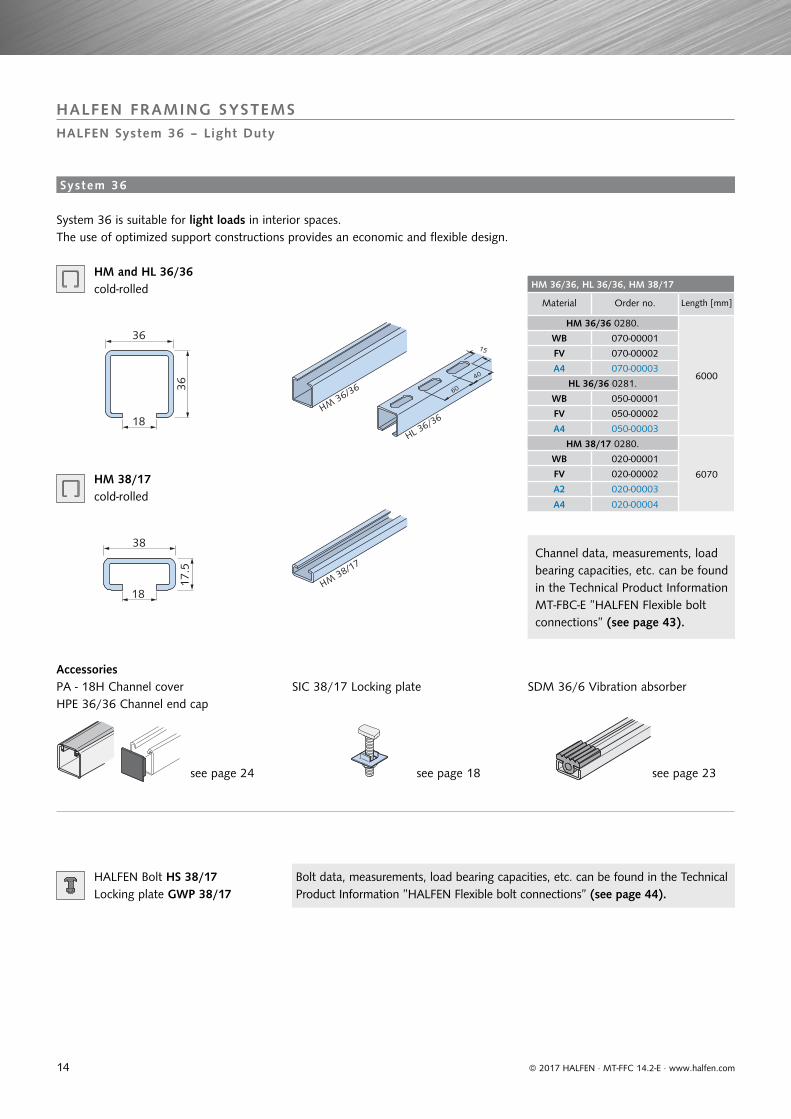
HM and HL 36/36 cold-rolled
HM 38/17 cold-rolled
System 36
System 36 is suitable for light loads in interior spaces. The use of optimized support constructions provides an economic and flexible design.
Accessories
Channel data, measurements, load bearing capacities, etc. can be found in the Technical Product Information MT-FBC-E ”HALFEN Flexible bolt connections” (see page 43).
Bolt data, measurements, load bearing capacities, etc. can be found in the Technical Product Information ”HALFEN Flexible bolt connections” (see page 44).
15
Connection elements – System 36
Article name
Order no.
FV - hot-dip galvanized
GV = zinc plated
0312.020-
A4 - stainless
steel
0312.020
HVT 36 - 1 - GV 00001
HVT 36 - 2 - GV 00002 00010
HVT 36 - 3 - GV 00003
HVT 36 - 4 - GV 00004
HVT 36 - 5 - GV 00005
HVT 36 - 6 - GV 00006
HVT 36 - 7 - FV 00007 00011
HVT 36 - 8 - GV 00008
HVT 36 - 9 - FV 00009
110
110
LL 11 x 30LL 11 x 25LL 11 x 50
LL 11 x 20
80
LL 11 x 25
36
LL 11 x 20
LL 11 x 2536
36
36
354
Ø 11
37103
130
Ø 1180
4
363545
Ø 11
1004025
LL 13 x 26
6
65
2 x LL 11 x 30
135
150
LL 13 x 2 6
Ø 13
150
4
Ø 1120
22060
20
6060
© 2017 HALFEN · MT-FFC 14.2-E · www.halfen.com
HALFEN FRAMING SYSTEMS
HALFEN System 36 – Light Duty
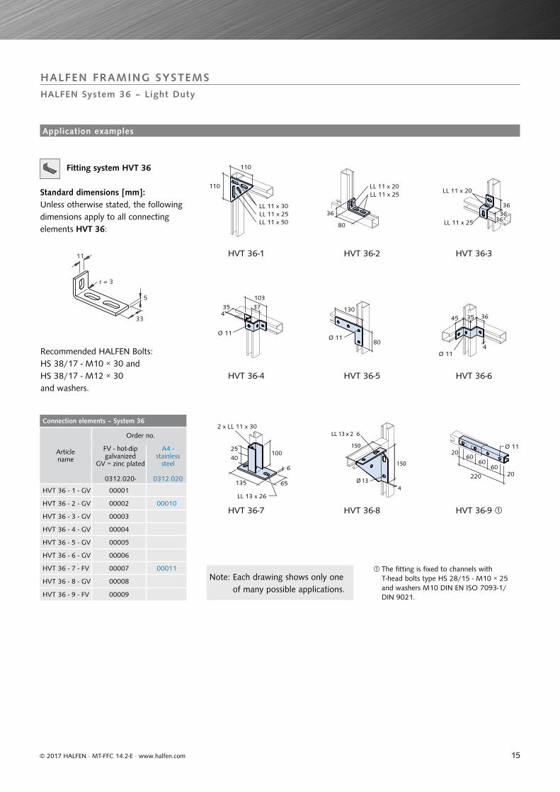
Fitting system HVT 36
Standard dimensions [mm]:Unless otherwise stated, the following dimensions apply to all connecting elements HVT 36:
Recommended HALFEN Bolts:HS 38/17 - M10 × 30 andHS 38/17 - M12 × 30and washers.
HVT 36-1
HVT 36-4
HVT 36-7
HVT 36-2
HVT 36-5
HVT 36-8
HVT 36-3
HVT 36-6
HVT 36-9
The fitting is fixed to channels with T-head bolts type HS 28/15 - M10 × 25 and washers M10 DIN EN ISO 7093-1/DIN 9021.
Note: Each drawing shows only one of many possible applications.
Application examples
5
11
33
r = 3
16
HM 28/28 and HL 28/28
Material Order no. Length [mm]
HM 28/28 0280.
6000
WB 050-00001SV 050-00003FV 050-00002A4 050-00004
HL 28/28 0281.WB 060-00001SV 060-00003FV 060-00002A4 060-00004
Fitting system HVT 28
FV = hot-dip galvanized GV = zinc plated
Order no.0312.010-
HVT 28 - 1 - GV 00001HVT 28 - 2 - GV 00002HVT 28 - 3 - GV 00003HVT 28 - 4 - GV 00004HVT 28 - 5 - GV 00005HVT 28 - 6 - GV 00006HVT 28 - 7 - FV 00007HVT 28 - 8 - GV 00008HVT 28 - 9 - FV 00009
28
12
27
HM28/28
12,5
25
40
HL 28/28
4
9
25
90
90
LL 9 x 26LL 9 x 30
LL 9 x 30
LL 9 x 26
70
LL 9 x 22LL 9 x 14
28
282835
LL 9 x 14
LL 9 x 26
3
Ø 9
27
80
29103
63Ø 9
3Ø 9
2728 33
LL 9 x 18
5
80
LL 9 x 18
100
2 x LL 9 x 26
LL 9 x 18
100
3Ø 9
100
Ø 9
20
HM 36/36
40160 20
4040
© 2017 HALFEN · MT-FFC 14.2-E · www.halfen.com
HALFEN FRAMING SYSTEMS
HALFEN System 28 – Light Duty
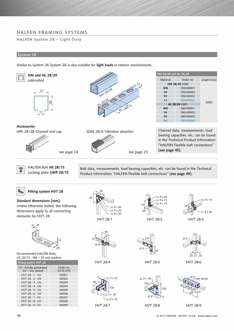
HM and HL 28/28 cold-rolled
Similar to System 36 System 28 is also suitable for light loads in interior environments.
SDM 28/6 Vibration absorberHPE 28/28 Channel end capAccessories
Channel data, measurements, load bearing capacities, etc. can be found in the Technical Product Information MT-FBC-E ”HALFEN Flexible bolt connections” (see page 45).
Channel data, measurements, load bearing capacities, etc. can be found in the Technical Product Information ”HALFEN Flexible bolt connections” (see page 45).see page 23 see page 24
HALFEN Bolt HS 28/15Locking plate GWP 28/15
Bolt data, measurements, load bearing capacities, etc. can be found in the Technical Product Information ”HALFEN Flexible bolt connections” (see page 49).
Fitting system HVT 28
Standard dimensions [mm]:Unless otherwise stated, the following dimensions apply to all connecting elements for HVT 28:
Recommended HALFEN Bolts:HS 28/15 - M8 × 20 and washers.
HVT 28-1
HVT 28-4
HVT 28-7
HVT 28-2
HVT 28-5
HVT 28-8
HVT 28-3
HVT 28-6
HVT 28-9
System 28
17
HL 36/36
HVT 36-2
HVT 36-7
HVT 36-7HL 36/36
HVT 28 - 7HL 28/28
HL 28/28
HVT 28 - 7
HL 28/28
HVT 28 - 2
© 2017 HALFEN · MT-FFC 14.2-E · www.halfen.com
HALFEN FRAMING SYSTEMS
HALFEN System 36 and System 28 – Light Duty – Construction Example
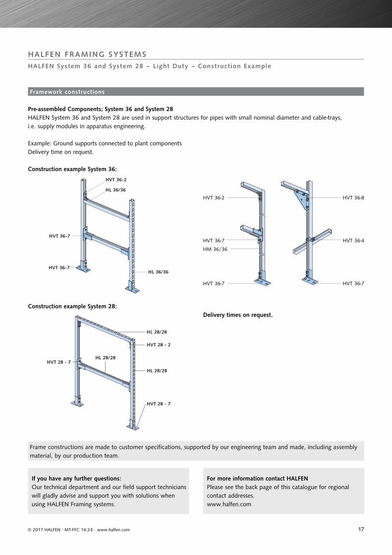
Pre-assembled Components; System 36 and System 28
Construction example System 36:
Construction example System 28:
Delivery time on request.
HVT 36-2 HVT 36-8
HVT 36-7
HVT 36-7 HVT 36-7
HVT 36-4
HM 36/36
Frame constructions are made to customer specifications, supported by our engineering team and made, including assembly material, by our production team.
HALFEN System 36 and System 28 are used in support structures for pipes with small nominal diameter and cable-trays, i.e. supply modules in apparatus engineering.
Example: Ground supports connected to plant components
Framework constructions
Delivery times on request.
If you have any further questions: Our technical department and our field support technicians will gladly advise and support you with solutions when using HALFEN Framing systems.
For more information contact HALFENPlease see the back page of this catalogue for regionalcontact addresses.www.halfen.com
18
GV A4 Suitable for HALFEN Bolts
galvanized stainless steel A4 type dimensions
SIC - 50/30 - GV SIC - 50/30 - A4 50/30 M16, M20
SIC - 40/22 - GV SIC - 40/22 - A4 38/1740/22 M16
SIC - 38/23 - GV 38/23 M16
SIC - 29/20 - GV 29/20 M12
SIC - 38/17 - GV SIC - 38/17 - A4 38/1740/22 M12, M10
SIC - 28/15 - GV SIC - 28/15 - A4 28/15 M8, M10
SIC - 20/12 - GV SIC - 20/12 - A4 20/12 M8
Ordering example: SIC - 38/17 - GV
GV A4 S/m S/m e
galvanized F.k.8
thread
stainless steel A4 DIN ISO
thread [mm] [mm] [mm]
M6 M6 10/5 10/6 11.5
M8 M8 13/6.5 13/7.5 15.0
M10 M10 17/8 16/ 9.5 19.6
M12 M12 19/10 18/12 21.9
M16 M16 24/13 24/15.5 27.7
M20 M20 30/16 30/19 34.6
M24 36/19 36/22 41.5
FV A2 S/m S/m ehot-dip
galvanized stainless steel A2 DIN EN
thread thread [mm] [mm] [mm]
M6, M8 M8 13/6.5 13/7.5 15.0
M10 M10 17/08 16/ 9.5 19.6
M12 M12 19/10 18/12 21.9
M16 M16 24/13 24/15.5 27.7
DIN
GV A4 D d s
galvanized stainless steel A4
[mm] [mm] [mm]for bolt for bolt
440 M6 22 6.6 2
9021 M8 M8 24 8.4 2
9021 M10 M10 30 10.5 2.5
440 M12 45 13.5 4
9021 M12 M12 37 13 3
9021 M16 M16 50 17 3
440 M20 72 22 6
Ordering example: US - M12 - GV -DIN 9021
GV A4 D d sgalvanized stainless
steel A4 for bolt [mm] [mm] [mm]for bolt
M6 M6 12 6.4 1.6
M8 M8 16 8.4 1.6
M10 M10 21 10.5 2
M12 M12 24 13 2.5
M16 M16 30 17 3
M20 M20 37 21 3
M24 44 25 4
50 28 4
56 31 4
FV A2 D d shot-dip
galvanized for bolt
stainless steel A2for bolt [mm] [mm] [mm]
M8 17 8.4 1.6M10 M10 21 10.5 2
M12 M12 24 13 2.5M16 M16 30 17 3
Ordering example: US - M12 - GV - DIN 125
FV A4 a × b × dhot-dip
galvanized for bolt
stainless steel A4 for bolts [mm]
VUS 40/25 for profile40/25;HZA 41/22
M10 M10 40 × 40 × 5
M12 M12 40 × 40 × 5
M16 M16 40 × 40 × 5
VUS 49/30 for profile 54/33,49/30
M10 M10 37 × 37 × 5
M12 M12 37 × 37 × 5
M16 M16 37 × 37 × 5
M20 M20 37 × 37 × 5
VUS 52/34 for profile52/34, 50/30
M16 M16 50 × 50 × 6
M20 M20 50 × 50 × 6
VUS 72/49 for profile72/48,72/49
M20 M20 54 × 54 × 6
M24 M24 54 × 54 × 6
M27 M27 54 × 54 × 6
M30 M30 54 × 54 × 6
VUS 41/41for all41 profiles
M6 M6 40 × 40 × 6
M10 M10 40 × 40 × 6
M12 M12 40 × 40 × 6
Ordering example: VUS 52/34 - FV - M20
© 2017 HALFEN · MT-FFC 14.2-E · www.halfen.com
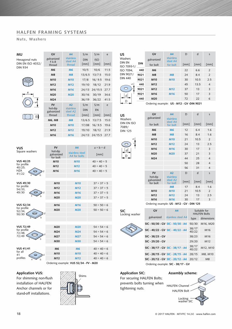
HALFEN FRAMING SYSTEMSNuts, Washers
SICLocking washer
Application SIC:For securing HALFEN Bolts; prevents bolts turning when tightening nuts.
MUHexagonal nutsDIN EN ISO 4032/DIN 934
USWashersDIN EN ISO 7093-1/ISO 7094,DIN 9021/ DIN 440
USWashersDIN EN ISO 7089/DIN 125
Application VUS:For shimming non-flush installation of HALFEN Anchor channels or for stand-off installations.
Shims
HALFEN Channel
Assembly scheme:
HALFEN Bolt
Locking washer SIC
VUSSquare washers
19
GV A4 D L FRd perm.F
galvanized
thread
stainless steel A4 thread [mm]
[mm]
[kN] [kN]
M6 M6 10/10 15 3.1 2.2
M8 M8 12/14 20 5.6 4.0
M10 M10 13/16 25 9.0 6.4
M12 M12 16/20 30 13.0 9.3
M16 M16 21/25 40 24.2 17.3
M20 M20 26/32 50 37.8 27.0
Ordering example: VBM - A4 - M16
FV A4 S L FRd perm.F
hot-dip galvanized
thread
stainless steel A4 thread [mm]
[mm]
[kN] [kN]
M10 M10 13 40 9.0 6.4
M12 M12 17 40 13.0 9.3
M16 M16 22 50 24.2 17.3
Ordering example: SKM - FV - M12
GV d FRd perm. F
C 15E, hot-dip galvanized thread
[mm]
[kN] [kN]
M8 20 2.0 1.4
M10 25 3.2 2.3
M12 30 4.8 3.4
M16 35 9.8 7.0
M20 40 16.8 12.0
Ordering example: RM - GV - M12
GV A4 Length FRd perm.F
galvanized FK 4.6thread
stainless steel A4 thread [mm]
[kN] [kN]
M6 M6 1000 3.1 2.2
M8 M8 1000 5.6 4.0
M10 M10 1000 9.0 6.4
M12 M12 1000 13.0 9.3
M16 M16 1000 24.2 17.3
M20 M20 1000 37.8 27.0
M24 1000 54.3 38.8
Ordering example: GWS - M12 × 1000 - GV
GV 8.8 A4 S S
galvanized F.K. 8.8
dimensions
stainless steel A4 DIN EN ISO
dimensions [mm] [mm]
M6 × 12 10
10 M6 × 25
M8 × 25 M8 × 2513 13
M8 × 40
M10 × 20
17 16
M10 × 30 M10 × 30
M10 × 45 M10 × 45
M10 × 60
M10 × 70
M12 × 22
19
18
M12 × 25 M12 × 25
M12 × 30 M12 × 30
M12 × 40 M12 × 40
M12 × 50
M12 × 60 M12 × 60
M12 × 80 M12 × 80
M12 × 90
M16 × 40 M16 × 40
24 24M16 × 60 M16 × 60
M16 × 90 M16 × 90
FV A4 t b d max FEd per.Fhot-dip
galvanized stainless
steel
type type [mm] [mm] [mm] [kN] [kN]
1 1 6 40 13 2.1 1.5
2 2 8 50 17 4.6 3.3
3 3 10 50 17 7.0 5
A4 A4 D D
stainless steel A4 thread M12
× length L [mm]
stainless steel A4thread M16
× length L [mm]
forM12[mm]
forM16[mm]
M12 × 60 M16 × 60 16 22
M12 × 75 M16 × 75 16 22
M12 × 95 M16 × 95 16 22
M12 × 115 M16 × 115 16 22
M12 × 135 M16 × 135 16 22
perm. F = 5 kN FRd = 7 kN
perm. F = 10 kN FRd = 14 kN
Ordering example: SPH - A4 - M12 × 75
© 2017 HALFEN · MT-FFC 14.2-E · www.halfen.com
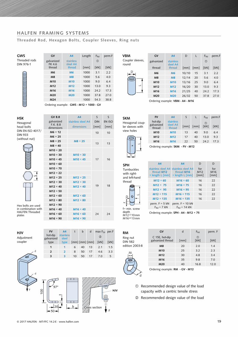
HALFEN FRAMING SYSTEMSThreaded Rod, Hexagon Bol ts , Coupler S leeves, R ing nuts
VBMCoupler sleeves, round
SKMHexagonal coup-ler sleeves with view holes
RMRing nutDIN 582 edition 2003-8
GWSThreaded rodsDIN 976-1
HSKHexagonal head boltsDIN EN ISO 4017/DIN 933(without nut)
Hex bolts are used in combination with HALFEN Threaded plates
HJVAdjustment coupler
SPHTurnbuckles with right- and left-hand thread
f= min. screw depthM12=10 mmM16=13 mm
Recommended design value of the loadcapacity with a centric tensile stress
Recommended design value of the load
Cross section
20
U-clamp-plate KUS
Type Order no.
KUS FV hot-dip galvanized 0314.000-00001
KUS A4 stainless steel 0314.000-00002
HVT 41 - 85
Type Order no.
HVT 41 - 85 - FV 0312.030-00042
HVT 41 - 85 - A4 0312.030-00085
FV = hot-dip galvanizedA4 = stainless steel
HVT 41 - 86
Type Order no.
HVT 41 - 86 - FV 0312.030-00044
HVT 41 - 86 - A4 0312.030-00086
FV = hot-dip galvanizedA4 = stainless steel
HVT 41 - 86
Type Order no.
HVT 41 - 89 - FV 0312.030-00046
HVT 41 - 89 - A4 on request
FV = hot-dip galvanizedA4 = stainless steel
Ø 13
40
15
50
4
6
22 75
86� 22
2275
127
6
22≤
1022
36
© 2017 HALFEN · MT-FFC 14.2-E · www.halfen.com
HALFEN FRAMING SYSTEMS
Adjustable Framework Construct ion – Accessor ies for System 41
Load cap. per clamp pair: 4.55 kN
HVT 41 - 85 HVT 41 - 86 HVT 41 - 89
Clamp thickness: max. 22 mm
Clamp thickness: max. 22 mm
Load cap. per clamp pair: 4.55 kN Load cap. per clamp pair: 3.0 kNLoad cap. per clamp pair for channel HLL 41/41: 2.5 kN
for channels 41/41, 41/22 and 41/22D for channels 41/41D, 41/62 and 41/83 for all channels in the 41 series
Clamp thickness: max. 22 mm
torque 12 Nm
Assembly diagram
KUS U-clamp-plates fit on all HALFEN 41 System channels
Threaded rod
e.g. channel 41/62
locking plate 41/41KUS
Beam clamps for 41 series; used in pairs
Beam clamps – 41 System
U-Clamp-Plate KUS – 41 System
21
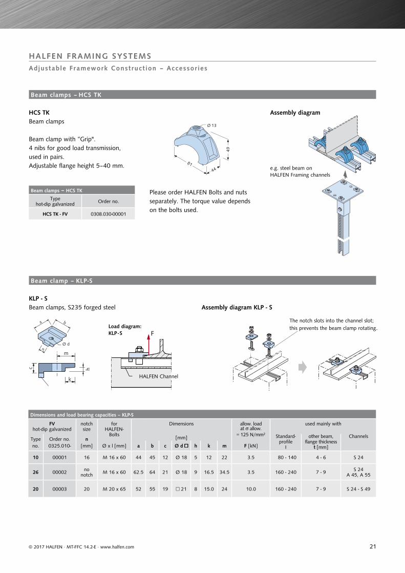
Beam clamps – HCS TK
Type hot-dip galvanized Order no.
HCS TK - FV 0308.030-00001
Dimensions and load bearing capacities – KLP-S
FV hot-dip galvanized
notch size
for HALFEN-
Bolts
Dimensions allow. loadat allow.
= 125 N/mm²
used mainly with
Type Order no. n [mm] Standard-profile
I
other beam,flange thickness
t [mm]
Channels
no. 0325.010- [mm] Ø x l [mm] a b c Ø d □□ h k m F [kN]
10 00001 16 M 16 x 60 44 45 12 Ø 18 5 12 22 3.5 80 - 140 4 - 6 S 24
26 00002 no notch M 16 x 60 62.5 64 21 Ø 18 9 16.5 34.5 3.5 160 - 240 7 - 9 S 24
A 45, A 55
20 00003 20 M 20 x 65 52 55 19 □ 21 8 15.0 24 10.0 160 - 240 7 - 9 S 24 - S 49
44
49
81
Ø 13
b
n
a
Ø d
F
© 2017 HALFEN · MT-FFC 14.2-E · www.halfen.com
HALFEN FRAMING SYSTEMS
Adjustable Framework Construct ion – Accessor ies
e.g. steel beam on HALFEN Framing channels
Please order HALFEN Bolts and nuts separately. The torque value depends on the bolts used.
HCS TK Beam clamps
Beam clamp with “Grip".4 nibs for good load transmission, used in pairs.Adjustable flange height 5–40 mm.
Assembly diagram
KLP - S Beam clamps, S235 forged steel
Beam clamps – HCS TK
Beam clamp – KLP-S
The notch slots into the channel slot; this prevents the beam clamp rotating.
Assembly diagram KLP - S
Load diagram: KLP - S
HALFEN Channel
22
Dimensions and load bearing capacities – KLP - 60
FV hot-dip galvanized
Clamping height h
allowable load used mainly with
Type Order no. Standard profiles
Standard profiles Railtracks-
0325.020- [mm] [kN] I HEB (IPB) crane-rails etc.
60/10 00001 10F1 = 7,0
HALFEN BoltsM 16 × 60, grade 4.6
120 - 160 100 A65, S 33, S 41
60/12 00002 12 220 - 240 140 A100, S 49, A75
60/14 00003 14 240 - 280 160 - 180 A120, S 54
60/16 00004 16F2 = 11,25
HALFEN BoltsM16 × 60, grade 8.8
300 - 340 200 - 220 S 64
60/18 00005 18 360 - 380 240 - 260 –
60/20 00006 20 400 - 450 280 - 300 –
T-head bolt M16 × 80 is required (bolt length depends on clamping height and channel type).Do not exceed HALFEN Framing channel bearing capacity! (The effect of the cantilever must be
considered when selecting HALFEN Channels and bolts). Check flange thickness of the channel.
LL 24 x 18
75
18
60
h
35
F1
F2
t g
© 2017 HALFEN · MT-FFC 14.2-E · www.halfen.com
HALFEN FRAMING SYSTEMS
Adjustable Framework Construct ion – Accessor ies
IPBHEB
KLP - 60 Beam clamps
Load diagramKLP - 60
Assembly diagramKLP - 60
Assembly example
e.g. HL 50/40
Beam clamps – KLP 60
HALFEN BoltHS 50/30
WasherUS DIN 125
HALFEN KLP Beam clamp
HALFEN Framing channelHL 50/40
HALFEN Locking plateGWP 50/40
Threaded rod with counter-nut and square washer VUS
Order example:
KLP - 60/10 - FV
Article nameDimensionsMaterial
23
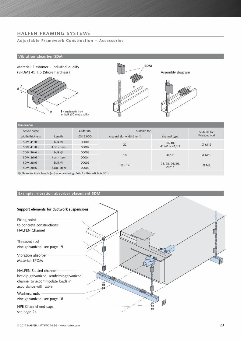
Dimensions
Article name Order no. Suitable for Suitable forthreaded rodwidth/thickness Length 0319.000- channel slot width [mm] channel type
SDM 41/8 - bulk 0000122 50/40,
41/41 – 41/83 Ø M12SDM 41/8 - 4 cm - item 00002
SDM 36/6 - bulk 0000318 36/36 Ø M10
SDM 36/6 - 4 cm - item 00004
SDM 28/6 - bulk 0000512 - 14 28/28, 26/26,
28/15 Ø M8SDM 28/6 - 4 cm - item 00006
Please indicate length [m] when ordering. Bulk for this article is 30 m.
Øb
d
SDM
© 2017 HALFEN · MT-FFC 14.2-E · www.halfen.com
HALFEN FRAMING SYSTEMS
Adjustable Framework Construct ion – Accessor ies
Material: Elastomer – Industrial quality (EPDM) 45 ± 5 (Shore hardness) Assembly diagram
Support elements for ductwork suspensions
Fixing pointto concrete constructions:HALFEN Channel
Threaded rodzinc galvanized, see page 19
Vibration absorberMaterial: EPDM
HALFEN Slotted channelhot-dip galvanized, sendzimir-galvanized channel to accommodate loads in accordance with table
Washers, nuts zinc galvanized, see page 18
HPE Channel end caps, see page 24
l = cut-length 4 cmor bulk (30 metre rolls)
Vibration absorber SDM
Example; vibration absorber placement SDM
24
Order no.
Type Length[mm]
Order no.0321.000-
PA - 41 - KS - 3000 00002
PA - 41 - SV - 3000 00001
PA - 22 - KS - 3000 00003
PA - 8H - KS - 3000 00004
Type overview
Type: PA 41 PA 22 PA 18 HSuitable for channel:50/40, 50/30, 486, for all 41 channels
Suitable for channel:52/34 Suitable for channel:
36/36, 38/17
#'
Material:Hard PVC
(KS)
41
21
9
22
15
5
white medium grey medium grey
Material:Steel
sendzimir-galvanized (SV)
41
21
9
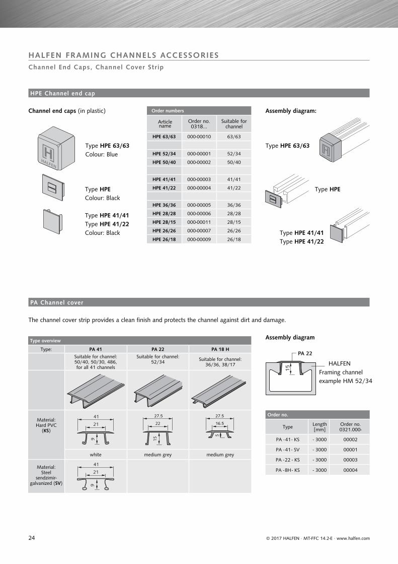
Order numbers
Articlename
Order no. 0318...
Suitable forchannel
HPE 63/63 000-00010 63/63
HPE 52/34 000-00001 52/34
HPE 50/40 000-00002 50/40
HPE 41/41 000-00003 41/41
HPE 41/22 000-00004 41/22
HPE 36/36 000-00005 36/36
HPE 28/28 000-00006 28/28
HPE 28/15 000-00011 28/15
HPE 26/26 000-00007 26/26
HPE 26/18 000-00009 26/18
27.5 27.5
16.5
HALFENHALFEN
PA 22
15
© 2017 HALFEN · MT-FFC 14.2-E · www.halfen.com
HALFEN FRAMING CHANNELS ACCESSORIESChannel End Caps, Channel Cover Strip
Assembly diagram:Channel end caps (in plastic)
Type HPE 63/63Colour: Blue
Type HPEColour: Black
Type HPE 41/41Type HPE 41/22Colour: Black
Type HPE 63/63
Type HPE
Type HPE 41/41Type HPE 41/22
HALFENFraming channel example HM 52/34
The channel cover strip provides a clean finish and protects the channel against dirt and damage.
Assembly diagram
HPE Channel end cap
PA Channel cover
25© 2017 HALFEN · MT-FFC 14.2-E · www.halfen.com
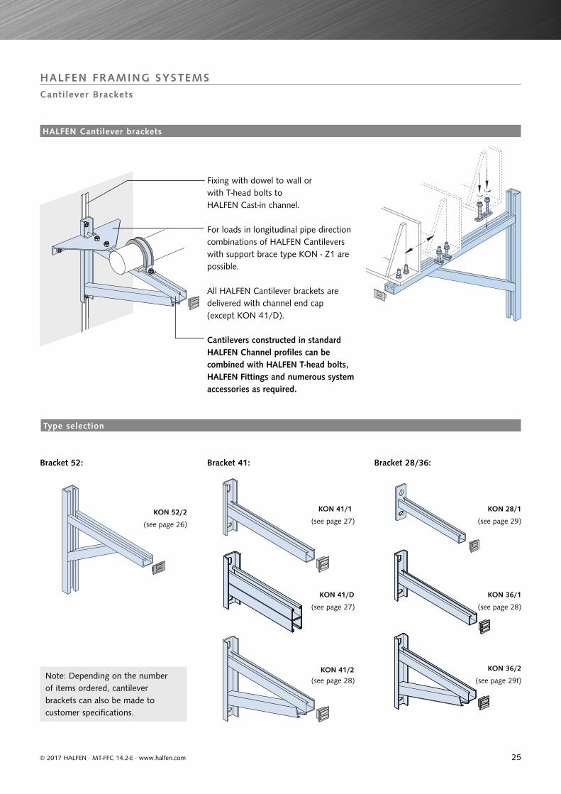
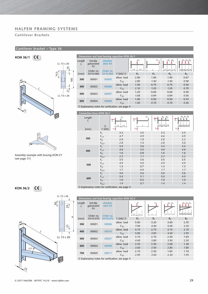
Fixing with dowel to wall or with T-head bolts to HALFEN Cast-in channel.
For loads in longitudinal pipe direction combinations of HALFEN Cantilevers with support brace type KON - Z1 are possible.
Cantilevers constructed in standard HALFEN Channel profiles can be combined with HALFEN T-head bolts, HALFEN Fittings and numerous system accessories as required.
All HALFEN Cantilever brackets are delivered with channel end cap (except KON 41/D).
KON 28/1
KON 36/1
KON 36/2
KON 41/1
KON 41/D
KON 41/2
KON 52/2
(see page 26) (see page 27) (see page 29)
(see page 28)(see page 27)
(see page 28) (see page 29f)
HALFEN FRAMING SYSTEMS
Cantilever Brackets
Type selection
HALFEN Cantilever brackets
Note: Depending on the number of items ordered, cantilever brackets can also be made to customer specifications.
Bracket 41:Bracket 52: Bracket 28/36:
26
Dimensions and load bearing capacities KON 52/2
Dimensions hot-dip galvanized
FV
stainless steel A4
LengthL
[mm]
HeightH
[mm]
LengthLS
[mm]Order no. 0310.080-
Order no. 0310.080- F [kN] F1 F1 F2
500 450 330 00001 00008allow. load 9.0 15.0 7.5
F Rd 12.6 21.0 10.5
600 475 380 00002 00009allow. load 8.0 15.0 7.5
F Rd 11.2 21.0 10.5
700 500 430 00003 00010allow. load 7.0 15.0 6.5
F Rd 9.8 21.0 9.1
800 550 480 00004 00011allow. load 6.0 15.0 6.0
F Rd 8.4 21.0 8.4
900 600 530 00005 00012allow. load 5.5 15.0 5.5
F Rd 7.7 21.0 7.7
1000 650 630 00006 00013allow. load 5.0 15.0 5.0
F Rd 7.0 21.0 7.0
1100 700 730 00007 00014allow. load 4.5 14.0 4.5
F Rd 6.3 19.6 6.3
on request Explanatory notes for verification, see page 4
Connection forces KON 52/2 Length
L
F [kN]
LengthL
F [kN] [mm][mm]
500
max. Fz 6.3 14.4 10.7
900
max. Fz 4.5 13.8 9.3max. Fz,d 8.8 20.0 14.8 max. Fz,d 6.3 19.1 12.9FQ 9.1 15.1 15.1 FQ 5.6 15.1 11.1FQ,d 12.7 21.1 21.1 FQ,d 7.9 21.2 15.6
600
max. Fz 6.0 14.1 11.4
1000
max. Fz 4.4 13.7 8.9max. Fz,d 8.3 19.5 15.8 max. Fz,d 6.1 18.9 12.3FQ 8.1 15.1 15.1 FQ 5.2 15.2 10.2FQ,d 11.3 21.1 21.1 FQ,d 7.2 21.2 14.2
700
max. Fz 5.5 14.0 10.3
1100
max. Fz 4.3 12.7 8.5max. Fz,d 7.5 19.3 14.3 max. Fz,d 5.9 17.5 11.8FQ 7.1 15.1 13.1 FQ 4.7 14.2 9.2FQ,d 10.0 21.2 18.4 FQ,d 6.5 19.8 12.8
800
max. Fz 4.8 13.9 9.8 Explanatory notes for verification, see page 4max. Fz,d 6.7 19.2 13.6FQ 6.1 15.1 12.1FQ,d 8.6 21.2 17.0
Dimensions KON 52/3 and KON 52/4 Length hot-dip galvanized
FV stainless steel
A4 suitable for bracket 52/2LSt
[mm] Order no. 0310. Order no. 0310.Length L
[mm]r
[mm]A
[mm]
KON 52/3
532 090-00001 090-00012 500 100 400602 090-00002 090-00013 600 150 450673 090-00003 090-00014 700 200 500744 090-00004 090-00015 800 250 550815 090-00005 090-00016 900 300 600961 090-00006 090-00017 1000 300 7001102 090-00007 090-00018 1100 300 800
KON 52/4 100-00002 100-00001 - - -
on requestused for additional bracing
30°
LS
L
34
H
50
H
135
100
LL 18 x 31
50
RL Ø 18
Lst
Ø 13
200
Ø 13
L/2L/2
1F
L/3L/3L/3
2F2F
L
1F
L/2L/2
FZ
FZ
FQ
1F
L/2L/2
FZ
FZ
FQ
1F
L/3L/3L/3
2F2FFZ
FZ
FQ
L/3L/3L/3
2F2FFZ
FZ
FQ
L
1FFZ
FZ
FQ
L
1FFZ
FZ
FQ
© 2017 HALFEN · MT-FFC 14.2-E · www.halfen.com
HALFEN FRAMING SYSTEMSCantilever Brackets
Fittings for bracket 52/2
KON 52/2
Bracing KON 52/3
Fixing bracket KON 52/4
KON 52/3
3 × VUS 52/34
KON 52/3 and KON 52/4for lateral bracing
Cant i lever brackets – Type 52
KON 52/4
27
Connection force KON 41/1
Length
F [kN]
L[mm]
175
Fz 3.5 3.5 3.5 3.5
Fz,d 4.9 4.9 4.9 4.8
FQ 5.4 2.7 5.4 5.3
FQ,d 7.5 3.8 7.5 7.4
325
Fz 3.3 3.2 3.2 3.1
Fz,d 4.6 4.5 4.5 4.4
FQ 2.7 1.4 2.7 2.6
FQ,d 3.8 1.9 3.7 3.6
475
Fz 3.2 3.1 3.1 3.0
Fz,d 4.4 4.3 4.3 4.2
FQ 1.8 0.9 1.8 1.7
FQ,d 2.5 1.3 2.4 2.4
Explanatory notes for verification, see page 4
Dimensions and load bearing capacities KON 41/1
Length hot-dip galvanized
FV
stainless steel A4
F [kN] L
[mm]Order no. 0310.010-
Order no. 0310.010- F1 F1 F2 F3
175 00001 00004allow. load 5.35 2.65 2.65 1.75
F Rd 7.49 3.71 3.71 2.45
325 00002 00005allow. load 2.65 1.30 1.30 0.85
F Rd 3.71 1.82 1.82 1.19
475 00003 00006allow. load 1.75 0.85 0.85 0.55
F Rd 2.45 1.19 1.19 0.77
Explanatory notes for verification, see page 4
51
L
25
ZF
FY
RL Ø13
r
M12 x 40HS 50/30
45°
200
L St
A
LL 13 x 26
180
2521
LL 13 x 26
70
L/2L/2
1F
L
1F
L/3L/3L/3
2F2F
L/4L/4 L/4 L/4
3F3F 3F
L/2L/2
F
1
Z
F
FQ
L
1FFZ
FQ
L/3L/3L/3
FZ
FQ
2F 2F
L/4L/4 L/4 L/4
FZ
FQ
3F 3F 3F
© 2017 HALFEN · MT-FFC 14.2-E · www.halfen.com
Note: The max. possible load of lateral braces depends on the allowable load (FZ) of the dowels.
Assembly example with bracing KON Z1 (see page 31)
Stainless steel brackets are fixed with locking plate GWP 50/30 - M12 and hexagonal bolt HSK - M12 × 60, DIN 933.
KON 52/4HS 50/30 - M12 × 60incl. nut
VUS 41/41(see page 19)
2x HS 50/30 - M12 × 40incl. nut (see page 6)
KON 52/3
KON 52/2
HALFEN FRAMING SYSTEMSCantilever Brackets
Dowel
Assembly diagram for lateral bracing
Cant i lever bracket – 52; continued
Cantilever bracket – Type 41
KON 41/1
28
Connection force KON 41/D
LengthL
F [kN] [mm]
325
Fz 6.9 6.9 6.9 6.8Fz,d 9.6 9.6 9.6 9.5FQ 5.7 2.9 5.7 5.6FQ,d 7.9 4.0 7.9 7.8
475
Fz 6.6 6.6 6.6 6.5Fz,d 3.8 9.3 9.3 9.0FQ 9.3 1.9 3.8 3.7FQ,d 5.3 2.7 5.3 5.1
625
Fz 6.7 6.7 6.7 6.4Fz,d 9.3 9.3 9.3 9.0FQ 2.9 1.5 2.9 2.8FQ,d 4.0 2.1 4.0 3.9
Explanatory notes for verification, see page 4
Dimensions and load bearing capacities KON 41/D
Length L
hot-dip galvanized
FV
stainless steel A4
F [kN] [mm]Order no. 0310.030-
Order no. 0310.030- F1 F1 F2 F3
325 00001 00004allow. load 5.60 2.80 2.80 1.85
F Rd 7.84 3.92 3.92 2.59
475 00002 00005allow. load 3.70 1.85 1.85 1.20
F Rd 5.18 2.59 2.59 1.68
625 00003 00006allow. load 2.80 1.40 1.40 0.90
F Rd 3.92 1.96 1.96 1.26Explanatory notes for verification, see page 4
Connection force KON 41/2
LengthL
F [kN] [mm]
325
Fz 5.5 6.8 7.0 7.5Fz,d 7.7 9.6 9.9 10.5FQ 7.6 4.9 9.7 10.3FQ,d 10.6 6.9 13.5 14.4
475
Fz 4.2 7.6 6.3 6.2Fz,d 6.0 10.8 8.8 8.8FQ 5.1 4.8 7.5 7.4FQ,d 7.1 6.7 10.5 10.4
625
Fz 3.4 6.3 5.2 5.3Fz,d 4.7 9.0 7.4 7.4FQ 3.6 3.6 5.6 5.6FQ,d 5.0 5.0 7.8 7.9
775
Fz 2.8 5.2 4.2 4.3Fz,d 3.9 7.3 6.0 6.1FQ 2.7 2.7 4.2 4.3FQ,d 3.8 3.8 5.9 6.0
Explanatory notes for verification, see page 4
Dimensions and load bearing capacities KON 41/2Size [mm] hot-dip
galvanized FV
stainless steel A4
F [kN] Order no. 0310.020-
Order no. 0310.020-
Length Height
L H F1 F1 F2 F3
325 270 00001 00005allow. load 7.50 4.90 4.80 3.40
F Rd 10.50 6.86 6.72 4.76
475 330 00002 00006allow. load 5.00 4.75 3.70 2.45
F Rd 7.00 6.65 5.18 3.43
625 380 00003 00007allow. load 3.50 3.50 2.75 1.85
F Rd 4.90 4.90 3.85 2.59775 430 00004 00008 allow. load 2.65 2.65 2.05 1.40
F Rd 3.71 3.71 2.87 1.96Explanatory notes for verification, see page 4
LL 13 x 26
LL 13 x 26
H
50
2521
25
L
H
L/2L/2
1F
L/2L/2
1F
FZ
FQ
L/3L/3L/3
2F2F
L/3L/3L/3
2F 2F
FZ
FQ
L
1F
L
1F
FZ
FQ
L/4L/4 L/4 L/4
3F3F 3F
L/4L/4 L/4 L/4
3F 3F 3F
FZ
FQ
L/2L/2
1F
FZ
FQ
L/2L/2
1F
L
1F
FZ
FQ
L
1F
L/3L/3L/3
2F2F
FZ
FQ
L/3L/3L/3
2F2F
L/4L/4 L/4 L/4
33 FF 3FFZ
FQ
L/4L/4 L/4 L/4
3F3F 3F
LL 13 x 26
180
2521
LL 13 x 2649
25
L
© 2017 HALFEN · MT-FFC 14.2-E · www.halfen.com
Assembly example with bracing KON Z1(see page 31)
Assembly example with bracing KON Z1(see page 31)
HALFEN FRAMING SYSTEMSCantilever Brackets
KON 42/2
KON 41/D
29
Connection force KON 36/1
LengthL
F [kN] [mm]
300
Fz 3.4 3.5 3.3 3.5Fz,d 4.7 4.9 4.6 4.9FQ 2.0 1.0 2.0 2.2FQ,d 2.8 1.4 2.8 3.0
400
Fz 3.4 3.6 3.4 3.4Fz,d 4.8 5.0 4.8 4.8FQ 1.6 0.8 1.6 1.6FQ,d 2.2 1.1 2.2 2.2
500
Fz 3.5 3.6 3.5 3.5Fz,d 4.9 5.0 4.9 4.9FQ 1.3 0.7 1.3 1.3FQ,d 1.7 0.9 1.7 1.7
600
Fz 3.6 3.6 3.6 3.6Fz,d 5.0 5.1 5.0 4.9FQ 1.0 0.5 1.0 1.0FQ,d 1.4 0.7 1.4 1.4
Explanatory notes for verification, see page 4
Dimensions and load bearing capacities KON 36/1
Length L
hot-dip galvanized
FV
stainless steel A4
[mm]Order no. 0310.060-
Order no. 0310.060- F [kN] F1 F1 F2 F3
300 00001 00005allow. load 2.00 1.00 1.00 0.67
F Rd 2.80 1.40 1.40 0.98
400 00002 00006allow. load 1.50 0.75 0.75 0.50
F Rd 2.10 1.05 1.05 0.70
500 00003 00007allow. load 1.20 0.60 0.60 0.40
F Rd 1.68 0.84 0.84 0.56
600 00004 00008allow. load 1.00 0.50 0.50 0.33
F Rd 1.40 0.70 0.70 0.46Explanatory notes for verification, see page 4
Dimensions and load bearing capacities KON 36/2
Length L
hot-dip galvanized
FV
stainless steel A4
F1
[mm]Order no. 0310.070-
Order no. 0310.070- F [kN] F1 F1 F2 F3
300 00001 00006allow. load 5.00 3.20 3.60 2.35
F Rd 7.00 4.40 5.00 3.30
400 00002 00010allow. load 4.15 2.75 3.15 2.10
F Rd 5.80 3.85 4.40 2.95
500 00003 00007allow. load 3.15 2.70 2.50 1.65
F Rd 4.40 3.80 3.50 2.30
600 00004 00009allow. load 2.55 2.50 2.00 1.30
F Rd 3.60 3.50 2.80 1.80
700 00005 00011allow. load 2.10 2.50 1.65 1.10
F Rd 2.95 3.50 2.30 1.55Explanatory notes for verification, see page 4
LL 13 x 26
H
25
21
LL 13 x 26
50
17°
46
25
L
L/2L/2
1F
L/3L/3L/3
2F2F
L
1F
L/4L/4 L/4 L/4
3F3F 3F
LL 13 x 26
LL 13 x 26
180
75, 5
2521
L/2L/2
1F
L/2L/2
1F
FZ
FQ
L
1F
L
1F
FZ
FQ
L/3L/3L/3
2F2F
L/3L/3L/3
FZ
FQ
2F 2F
L/4L/4 L/4 L/4
3F3F 3F
L/4L/4 L/4 L/4
FZ
FQ
3F 3F 3F
46
25
L
© 2017 HALFEN · MT-FFC 14.2-E · www.halfen.com
KON 36/2
HALFEN FRAMING SYSTEMS Cantilever Brackets
KON 36/1
Assembly example with bracing KON Z1(see page 31)
Cantilever bracket – Type 36
30
Connection force KON 36/2
Length
F [kN] L
[mm]
300
Fz 4.9 5.6 6.7 6.4Fz,d 6.9 7.9 9.4 8.9FQ 5.0 3.1 7.2 7.1FQ,d 7.0 4.4 10.1 9.9
400
Fz 5.2 6.2 7.3 7.1Fz,d 7.3 8.7 10.2 9.9FQ 4.2 2.8 6.3 6.3FQ,d 5.8 3.9 8.9 8.9
500
Fz 4.9 7.1 7.1 6.7Fz,d 6.8 9.9 9.9 9.4FQ 3.2 2.7 5.0 5.0FQ,d 4.5 3.8 7.0 7.0
600
Fz 4.6 7.3 6.6 6.1Fz,d 6.4 10.2 9.3 8.6FQ 2.6 2.5 4.0 3.9FQ,d 3.6 3.5 5.7 5.5
700
Fz 4.4 8.2 6.3 5.9Fz,d 6.1 11.5 8.8 8.3FQ 2.1 2.6 3.3 3.3FQ,d 3.0 3.6 4.7 4.7
Explanatory notes for verification, see page 4
Connection force KON 28/1
Length
F [kN] L
[mm]
100
Fz 1.9 1.9 1.9 1.9Fz,d 2.6 2.6 2.6 2.6FQ 2.7 1.4 2.7 2.7FQ,d 3.8 1.9 3.8 3.8
200
Fz 1.9 1.9 1.9 1.9Fz,d 2.6 2.6 2.6 2.6FQ 1.4 0.7 1.4 1.4FQ,d 1.9 1.0 2.0 1.9
300
Fz 1.9 1.9 1.9 1.9Fz,d 2.6 2.6 2.6 2.6FQ 1.0 0.5 1.0 1.0FQ,d 1.3 0.7 1.3 1.3
400
Fz 1.9 1.9 1.9 1.7Fz,d 2.7 2.7 2.7 2.3FQ 0.8 0.4 0.8 0.7FQ,d 1.0 0.5 1.0 0.9
Explanatory notes for verification, see page 4
Dimensions and load bearing capacities KON 28/1
Length hot-dip galvanized
FV
stainless steel A4
L [mm]
Order no. 0310.050-
Order no. 0310.050- F [kN] F1 F1 F2 F3
100 00001 00005allow. load 2.70 1.35 1.35 0.90
F Rd 3.78 1.89 1.89 1.26
200 00002 00006allow. load 1.35 0.68 0.68 0.45
F Rd 1.89 0.95 0.95 0.63
300 00003 00007allow. load 0.90 0.45 0.45 0.30
F Rd 1.26 0.63 0.63 0.42
400 00004 00008allow. load 0.70 0.35 0.35 0.20
F Rd 0.98 0.49 0.49 0.28Explanatory notes for verification, see page 4
L
1F
L/2L/2
1F
FZ
FQ
L/2L/2
1F
L
1F
FZ
FQ
L/3L/3L/3
2F2F
L/3L/3L/3
FZ
FQ
2F 2F
L/4L/4 L/4 L/4
3F3F 3F
L/4L/4 L/4 L/4
FZ
FQ
3F 3F 3F
LL 13 x 20
25
46
21
120
LL 13 x 20
6
40
L
L/3L/3L/3
2F 2F
FZ
FQ
L/4L/4 L/4 L/4
3F 3F 3F
FZ
FQ
L/2L/2
1F
FZ
FQ
L
1F
FZ
FQ
© 2017 HALFEN · MT-FFC 14.2-E · www.halfen.com
HALFEN FRAMING SYSTEMSCantilever Brackets
Assembly example with bracing KON Z1(see page 31)
KON 28/1
Cantilever bracket – Type 28
Assembly example with bracing KON Z1(see page 31)
31
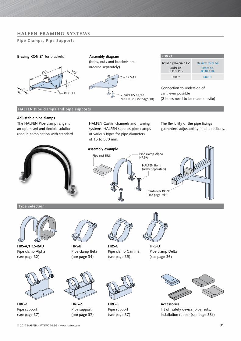
KON Z1
hot-dip galvanized FV stainless steel A4
Order no. 0310.110-
Order no. 0310.110-
00002 00001
45
55
165
5
350
RL Ø 13
© 2017 HALFEN · MT-FFC 14.2-E · www.halfen.com
Assembly diagram(bolts, nuts and brackets are ordered separately)
Connection to underside of cantilever possible (2 holes need to be made on-site)
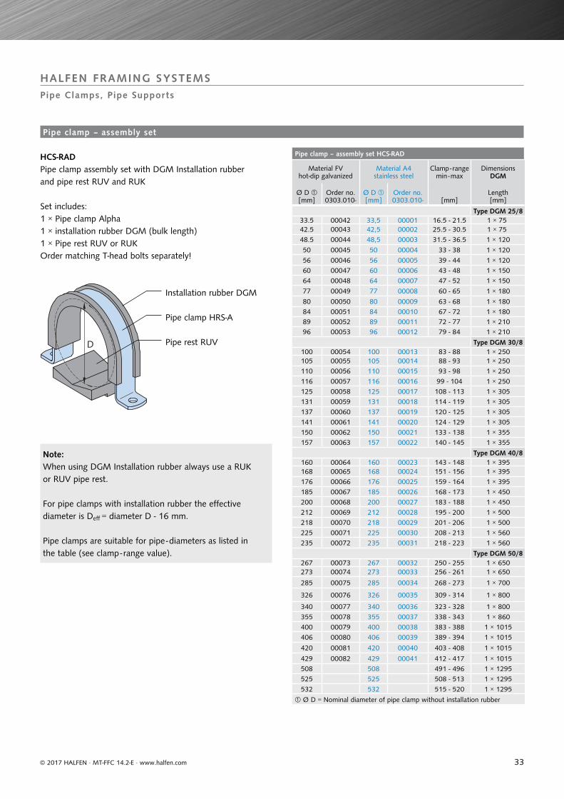
The HALFEN Pipe clamp range is an optimised and flexible solution used in combination with standard
HALFEN Cast-in channels and framing systems. HALFEN supplies pipe clamps of various types for pipe diameters of 15 to 530 mm.
The flexibility of the pipe fixings guarantees adjustability in all directions.
Assembly examplePipe clamp AlphaHRS-A
Pipe rest RUK
HALFEN Bolts (order separately)
Cantilever KON(see page 25 f)
HALFEN FRAMING SYSTEMSPipe Clamps, Pipe Supports
Adjustable pipe clamps
HRS-A/HCS-RADPipe clamp Alpha(see page 32)
HRG-1Pipe support(see page 37)
HRS-BPipe clamp Beta(see page 34)
HRG-2Pipe support(see page 37)
HRS-GPipe clamp Gamma(see page 35)
HRG-3Pipe support(see page 37)
Accessorieslift off safety device, pipe rests, installation rubber (see page 38 f)
HRS-DPipe clamp Delta(see page 36)
2 bolts HS 41/41M12 × 35 (see page 10)
2 nuts M12
HALFEN Pipe clamps and pipe supports
Type selection
Bracing KON Z1 for brackets
32
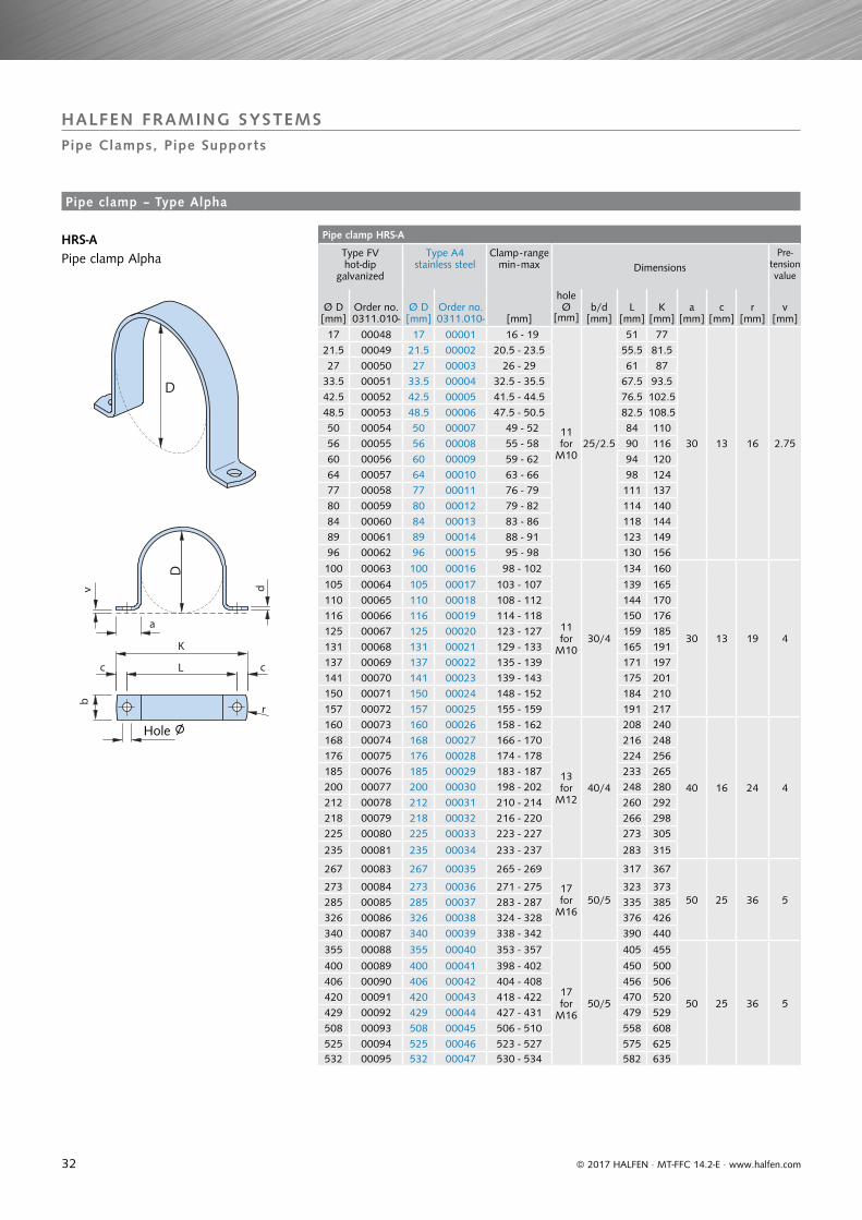
Pipe clamp HRS-A
Type FV hot-dip
galvanized
Type A4stainless steel
Clamp - rangemin - max Dimensions
Pre-tension value
Ø D [mm]
Order no.0311.010-
Ø D [mm]
Order no.0311.010- [mm]
hole Ø
[mm]b/d
[mm]L
[mm]K
[mm]a
[mm]c
[mm]r
[mm]v
[mm]
17 00048 17 00001 16 - 19
11 for
M1025/2.5
51 77
30 13 16 2.75
21.5 00049 21.5 00002 20.5 - 23.5 55.5 81.527 00050 27 00003 26 - 29 61 87
33.5 00051 33.5 00004 32.5 - 35.5 67.5 93.542.5 00052 42.5 00005 41.5 - 44.5 76.5 102.548.5 00053 48.5 00006 47.5 - 50.5 82.5 108.550 00054 50 00007 49 - 52 84 11056 00055 56 00008 55 - 58 90 11660 00056 60 00009 59 - 62 94 12064 00057 64 00010 63 - 66 98 12477 00058 77 00011 76 - 79 111 13780 00059 80 00012 79 - 82 114 14084 00060 84 00013 83 - 86 118 14489 00061 89 00014 88 - 91 123 14996 00062 96 00015 95 - 98 130 156
100 00063 100 00016 98 - 102
11for
M1030/4
134 160
30 13 19 4
105 00064 105 00017 103 - 107 139 165110 00065 110 00018 108 - 112 144 170116 00066 116 00019 114 - 118 150 176125 00067 125 00020 123 - 127 159 185131 00068 131 00021 129 - 133 165 191137 00069 137 00022 135 - 139 171 197141 00070 141 00023 139 - 143 175 201150 00071 150 00024 148 - 152 184 210157 00072 157 00025 155 - 159 191 217160 00073 160 00026 158 - 162
13for
M1240/4
208 240
40 16 24 4
168 00074 168 00027 166 - 170 216 248176 00075 176 00028 174 - 178 224 256185 00076 185 00029 183 - 187 233 265200 00077 200 00030 198 - 202 248 280212 00078 212 00031 210 - 214 260 292218 00079 218 00032 216 - 220 266 298225 00080 225 00033 223 - 227 273 305
235 00081 235 00034 233 - 237 283 315
267 00083 267 00035 265 - 269
17for
M1650/5
317 367
50 25 36 5273 00084 273 00036 271 - 275 323 373285 00085 285 00037 283 - 287 335 385326 00086 326 00038 324 - 328 376 426340 00087 340 00039 338 - 342 390 440
355 00088 355 00040 353 - 357
17for
M1650/5
405 455
50 25 36 5
400 00089 400 00041 398 - 402 450 500406 00090 406 00042 404 - 408 456 506420 00091 420 00043 418 - 422 470 520429 00092 429 00044 427 - 431 479 529508 00093 508 00045 506 - 510 558 608525 00094 525 00046 523 - 527 575 625532 00095 532 00047 530 - 534 582 635
D
v d
b
K
L cc
a
r
D
© 2017 HALFEN · MT-FFC 14.2-E · www.halfen.com
HRS-A Pipe clamp Alpha
HALFEN FRAMING SYSTEMSPipe Clamps, Pipe Supports
Hole ∅
Pipe clamp – Type Alpha
33
Pipe clamp – assembly set HCS-RAD
Material FV hot-dip galvanized
Material A4stainless steel
Clamp - range min - max
DimensionsDGM
Ø D [mm]
Order no.0303.010-
Ø D [mm]
Order no.0303.010- [mm]
Length[mm]
Type DGM 25/833.5 00042 33,5 00001 16.5 - 21.5 1 × 75 42.5 00043 42,5 00002 25.5 - 30.5 1 × 75 48.5 00044 48,5 00003 31.5 - 36.5 1 × 120
50 00045 50 00004 33 - 38 1 × 120
56 00046 56 00005 39 - 44 1 × 12060 00047 60 00006 43 - 48 1 × 15064 00048 64 00007 47 - 52 1 × 150
77 00049 77 00008 60 - 65 1 × 180
80 00050 80 00009 63 - 68 1 × 18084 00051 84 00010 67 - 72 1 × 18089 00052 89 00011 72 - 77 1 × 21096 00053 96 00012 79 - 84 1 × 210
Type DGM 30/8100 00054 100 00013 83 - 88 1 × 250105 00055 105 00014 88 - 93 1 × 250110 00056 110 00015 93 - 98 1 × 250116 00057 116 00016 99 - 104 1 × 250125 00058 125 00017 108 - 113 1 × 305131 00059 131 00018 114 - 119 1 × 305137 00060 137 00019 120 - 125 1 × 305141 00061 141 00020 124 - 129 1 × 305150 00062 150 00021 133 - 138 1 × 355157 00063 157 00022 140 - 145 1 × 355
Type DGM 40/8160 00064 160 00023 143 - 148 1 × 395168 00065 168 00024 151 - 156 1 × 395176 00066 176 00025 159 - 164 1 × 395185 00067 185 00026 168 - 173 1 × 450200 00068 200 00027 183 - 188 1 × 450212 00069 212 00028 195 - 200 1 × 500218 00070 218 00029 201 - 206 1 × 500225 00071 225 00030 208 - 213 1 × 560235 00072 235 00031 218 - 223 1 × 560
Type DGM 50/8267 00073 267 00032 250 - 255 1 × 650273 00074 273 00033 256 - 261 1 × 650
285 00075 285 00034 268 - 273 1 × 700
326 00076 326 00035 309 - 314 1 × 800
340 00077 340 00036 323 - 328 1 × 800355 00078 355 00037 338 - 343 1 × 860400 00079 400 00038 383 - 388 1 × 1015406 00080 406 00039 389 - 394 1 × 10¹⁵
420 00081 420 00040 403 - 408 1 × 10¹⁵
429 00082 429 00041 412 - 417 1 × 1015508 508 491 - 496 1 × 1295525 525 508 - 513 1 × 1295532 532 515 - 520 1 × 1295
Ø D = Nominal diameter of pipe clamp without installation rubber
D
© 2017 HALFEN · MT-FFC 14.2-E · www.halfen.com
HCS-RADPipe clamp assembly set with DGM Installation rubber and pipe rest RUV and RUK
Set includes:1 × Pipe clamp Alpha1 × installation rubber DGM (bulk length)1 × Pipe rest RUV or RUK
Installation rubber DGM
Order matching T-head bolts separately!
Pipe clamp HRS-A
Pipe rest RUV
Note:When using DGM Installation rubber always use a RUK or RUV pipe rest.
For pipe clamps with installation rubber the effective diameter is Deff = diameter D - 16 mm.
Pipe clamps are suitable for pipe - diameters as listed in the table (see clamp - range value).
HALFEN FRAMING SYSTEMSPipe Clamps, Pipe Supports
Pipe clamp – assembly set
34
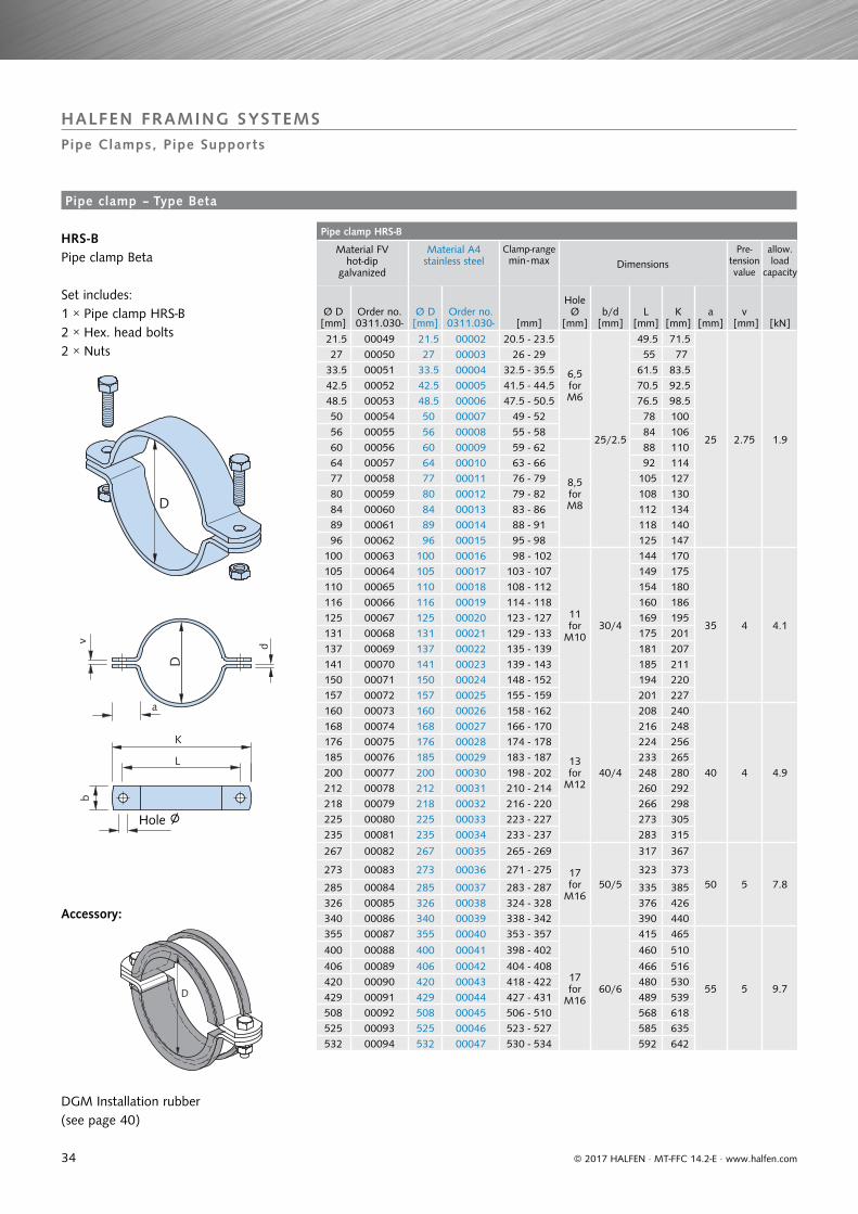
Pipe clamp HRS-B
Material FV hot-dip
galvanized
Material A4stainless steel
Clamp-range min - max Dimensions
Pre- tension value
allow.load
capacity
Ø D [mm]
Order no.0311.030-
Ø D [mm]
Order no.0311.030- [mm]
Hole Ø
[mm]b/d
[mm]L
[mm]K
[mm]a
[mm]v
[mm] [kN]
21.5 00049 21.5 00002 20.5 - 23.5
6,5 for M6
25/2.5
49.5 71.5
25 2.75 1.9
27 00050 27 00003 26 - 29 55 77 33.5 00051 33.5 00004 32.5 - 35.5 61.5 83.5 42.5 00052 42.5 00005 41.5 - 44.5 70.5 92.5 48.5 00053 48.5 00006 47.5 - 50.5 76.5 98.5 50 00054 50 00007 49 - 52 78 100 56 00055 56 00008 55 - 58 84 106 60 00056 60 00009 59 - 62
8,5 for M8
88 110 64 00057 64 00010 63 - 66 92 114 77 00058 77 00011 76 - 79 105 127 80 00059 80 00012 79 - 82 108 130 84 00060 84 00013 83 - 86 112 134 89 00061 89 00014 88 - 91 118 140 96 00062 96 00015 95 - 98 125 147100 00063 100 00016 98 - 102
11 for
M1030/4
144 170
35 4 4.1
105 00064 105 00017 103 - 107 149 175110 00065 110 00018 108 - 112 154 180116 00066 116 00019 114 - 118 160 186125 00067 125 00020 123 - 127 169 195131 00068 131 00021 129 - 133 175 201137 00069 137 00022 135 - 139 181 207141 00070 141 00023 139 - 143 185 211150 00071 150 00024 148 - 152 194 220157 00072 157 00025 155 - 159 201 227160 00073 160 00026 158 - 162
13 for
M1240/4
208 240
40 4 4.9
168 00074 168 00027 166 - 170 216 248176 00075 176 00028 174 - 178 224 256185 00076 185 00029 183 - 187 233 265200 00077 200 00030 198 - 202 248 280212 00078 212 00031 210 - 214 260 292218 00079 218 00032 216 - 220 266 298225 00080 225 00033 223 - 227 273 305235 00081 235 00034 233 - 237 283 315
267 00082 267 00035 265 - 269
17 for
M1650/5
317 367
50 5 7.8273 00083 273 00036 271 - 275 323 373
285 00084 285 00037 283 - 287 335 385326 00085 326 00038 324 - 328 376 426340 00086 340 00039 338 - 342 390 440355 00087 355 00040 353 - 357
17 for
M1660/6
415 465
55 5 9.7
400 00088 400 00041 398 - 402 460 510
406 00089 406 00042 404 - 408 466 516420 00090 420 00043 418 - 422 480 530429 00091 429 00044 427 - 431 489 539508 00092 508 00045 506 - 510 568 618525 00093 525 00046 523 - 527 585 635532 00094 532 00047 530 - 534 592 642
D
D
v d
a
b
K
L
D
© 2017 HALFEN · MT-FFC 14.2-E · www.halfen.com
HALFEN FRAMING SYSTEMSPipe Clamps, Pipe Supports
HRS-BPipe clamp Beta
Set includes:1 × Pipe clamp HRS-B2 × Hex. head bolts2 × Nuts
DGM Installation rubber(see page 40)
Accessory:
Hole ∅
Pipe clamp – Type Beta
35
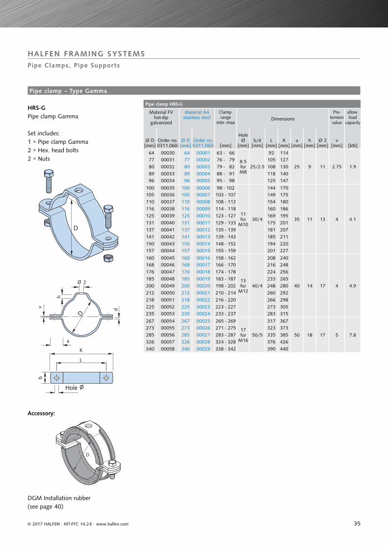
Pipe clamp HRS-G
Material FV hot-dip
galvanized
Material A4stainless steel
Clamp-range
min - maxDimensions
Pre-tension value
allow.load
capacity
Ø D [mm]
Order no.0311.060-
Ø D [mm]
Order no.0311.060- [mm]
Hole Ø
[mm]b/d
[mm]L
[mm]K
[mm]a
[mm]h
[mm]Ø 2
[mm]v
[mm] [kN]
64 00030 64 00001 63 - 66
8.5 for M8
25/2.5
92 114
25 9 11 2.75 1.9 77 00031 77 00002 76 - 79 105 127 80 00032 80 00003 79 - 82 108 130 89 00033 89 00004 88 - 91 118 140 96 00034 96 00005 95 - 98 125 147
100 00035 100 00006 98 - 102
11 for
M1030/4
144 170
35 11 13 4 4.1
105 00036 105 00007 103 - 107 149 175110 00037 110 00008 108 - 112 154 180116 00038 116 00009 114 - 118 160 186125 00039 125 00010 123 - 127 169 195131 00040 131 00011 129 - 133 175 201137 00041 137 00012 135 - 139 181 207141 00042 141 00013 139 - 143 185 211150 00043 150 00014 148 - 152 194 220157 00044 157 00015 155 - 159 201 227
160 00045 160 00016 158 - 162
13 for
M1240/4
208 240
40 14 17 4 4.9
168 00046 168 00017 166 - 170 216 248176 00047 176 00018 174 - 178 224 256185 00048 185 00019 183 - 187 233 265200 00049 200 00020 198 - 202 248 280212 00050 212 00021 210 - 214 260 292218 00051 218 00022 216 - 220 266 298225 00052 225 00023 223 - 227 273 305235 00053 235 00024 233 - 237 283 315
267 00054 267 00025 265 - 269
17 for
M1650/5
317 367
50 18 17 5 7.8
273 00055 273 00026 271 - 275 323 373285 00056 285 00027 283 - 287 335 385326 00057 326 00028 324 - 328 376 426340 00058 340 00029 338 - 342 390 440
D
b
K
L
h
Ø 2
D
v d
a
D
© 2017 HALFEN · MT-FFC 14.2-E · www.halfen.com
HALFEN FRAMING SYSTEMSPipe Clamps, Pipe Supports
DGM Installation rubber (see page 40)
HRS-GPipe clamp Gamma
Set includes:1 × Pipe clamp Gamma2 × Hex. head bolts2 × Nuts
Accessory:
Hole ∅
Pipe clamp – Type Gamma
36
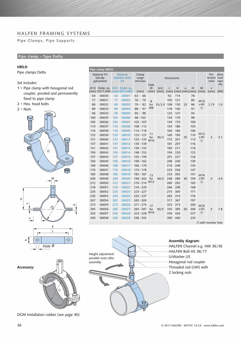
Pipe clamp HRS-D
Material FV hot-dip
galvanized
Materialstainless steel
A4
Clamp range
min-maxDimensions
Pre- tension value
allow.load capa-city
Ø D [mm]
Order no.0311.050-
Ø D [mm]
Order no.0311.050- [mm]
Hole Ø
[mm]b/d
[mm]L
[mm]K
[mm]a
[mm]H
[mm]M
[mm]v
[mm] [kN]
64 00030 64 00001 63 - 66
8 for M8
25/2.5
92 114
25
78
M10x 40
2.75 1.9
77 00031 77 00002 76 - 79 105 127 85 80 00032 80 00003 79 - 82 108 130 86 89 00033 89 00004 88 - 91 118 140 91
96 00034 96 00005 95 - 98 125 147 94
100 00035 100 00006 98 - 102
11 for
M1030/4
144 170
35
98
M12x 40
4 4.1
105 00036 105 00007 103 - 107 149 175 100110 00037 110 00008 108 - 112 154 180 103116 00038 116 00009 114 - 118 160 186 106125 00039 125 00010 123 - 127 169 195 110131 00040 131 00011 129 - 133 175 201 113137 00041 137 00012 135 - 139 181 207 116141 00042 141 00013 139 - 143 185 211 118150 00043 150 00014 148 - 152 194 220 123157 00044 157 00015 155 - 159 201 227 126160 00045 160 00016 158 - 162
13 for
M1240/4
208 240
40
139
M16x 50
4 4.9
168 00046 168 00017 166 - 170 216 248 143176 00047 176 00018 174 - 178 224 256 147185 00048 185 00019 183 - 187 233 265 151200 00049 200 00020 198 - 202 248 280 159212 00050 212 00021 210 - 214 260 292 165218 00051 218 00022 216 - 220 266 298 168225 00052 225 00023 223 - 227 273 305 171235 00053 235 00024 233 - 237 283 315 176267 00054 267 00025 265 - 269
17 for
M1650/5
317 367
50
197
M16x 50
5 7.8
273 00055 273 00026 271 - 275 323 373 200285 00056 285 00027 283 - 287 335 385 206326 00057 326 00028 324 - 328 376 426 227
340 00058 340 00029 338 - 342 390 440 234
with monitor hole
D
b
KL
H
M
D
v d
a
D
© 2017 HALFEN · MT-FFC 14.2-E · www.halfen.com
HRS-DPipe clamps Delta
Set includes: 1 × Pipe clamp with hexagonal rod
coupler, pivoted and permanently fixed to pipe clamp
2 × Hex. head bolts 2 × Nuts
Assembly diagram:HALFEN Channel e.g. HM 36/36HALFEN Bolt HS 38/17U-Washer US
Threaded rod GWS with 2 locking nuts
Hexagonal rod coupler
Height adjustment possible even after assembly
HALFEN FRAMING SYSTEMSPipe Clamps, Pipe Supports
DGM Installation rubber (see page 40)
Accessory:
Pipe clamp – Type Delta
Hole ∅
37
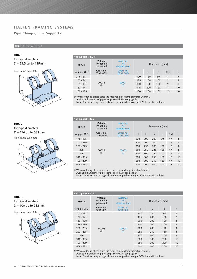
Pipe support HRG-1
HRG-1
Material: FV hot-dip galvanized
Material: A4
stainless steelDimensions [mm]
for pipe- Ø D Order no.0291.-009-
Order no.0291.009- H L b Ø d t
21,5 - 60
00004
00001
100 130 80 11 5
63 - 84 125 150 100 11 8
89 - 131 150 180 100 11 8
137 - 141 175 200 120 11 10
150 - 185 200 200 150 13 10
When ordering please state the required pipe clamp diameter-Ø [mm]. Available diameters of pipe clamps see HRS-B, see page 34. Note: Consider using a larger diameter clamp when using a DGM Installation rubber.
Pipe support HRG-2
HRG-2
Material: FV hot-dip galvanized
Material: A4
stainless steelDimensions [mm]
for pipe- Ø D Order no.0291.-009-
Order no.0291.009- H L b c Ø d t
176 - 185
00005
00002
200 200 200 80 17 8
200 - 235 200 200 200 100 17 8
267 - 273 250 250 200 100 17 8
285 250 250 225 125 17 8
326 250 300 250 150 17 10
340 - 355 300 300 250 150 17 10
400 - 429 350 300 250 150 17 10
508 - 532 400 400 300 200 22 15
When ordering please state the required pipe clamp diameter-Ø [mm]. Available diameters of pipe clamps see HRS-B, see page 34. Note: Consider using a larger diameter clamp when using a DGM Installation rubber.
Pipe support HRG-3
HRG-3
Material: FV hot-dip galvanized
Material: A4
stainless steelDimensions [mm]
for pipe- Ø D Order no.0291.-009-
Order no.0291.009- H L b t
100 - 131
00006
00003
150 180 80 5
137 - 141 175 200 100 5
150 - 168 200 200 100 5
176 - 185 200 200 100 8
200 - 235 200 200 120 8
267 - 285 250 250 150 8
326 250 300 150 8
340 - 355 300 300 200 10
400 - 429 350 300 200 10
508 - 532 400 400 250 10
When ordering please state the required pipe clamp diameter-Ø [mm].Available diameters of pipe clamps see HRS-B, see page 34.Note: Consider using a larger diameter clamp when using a DGM Installation rubber.
Ød
H
t
5b L
D
5
Ø dc
H
t
b
D
L
t
b
H
L
D
© 2017 HALFEN · MT-FFC 14.2-E · www.halfen.com
HALFEN FRAMING SYSTEMSPipe Clamps, Pipe Supports
HRG-1 for pipe diameters D = 21.5 up to 185 mm
HRG-2 for pipe diameters D = 176 up to 532 mm
Pipe clamp type Beta
Pipe clamp type Beta
Pipe clamp type Beta
HRG-3 for pipe diameters D = 100 up to 532 mm
HRG Pipe support
38
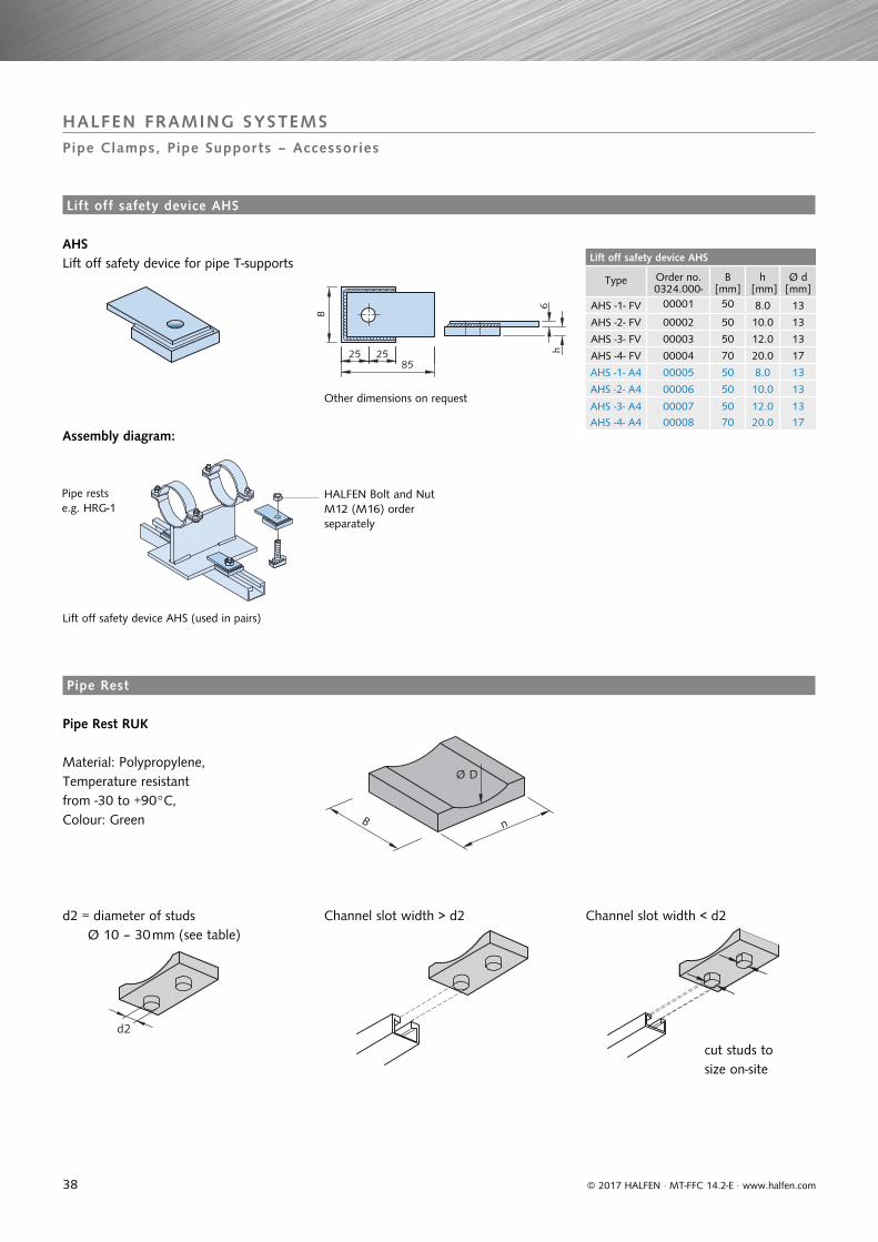
Lift off safety device AHS
Type Order no. 0324.000-
B[mm]
h [mm]
Ø d[mm]
AHS -1- FV 00001 50 8.0 13
AHS -2- FV 00002 50 10.0 13
AHS -3- FV 00003 50 12.0 13
AHS -4- FV 00004 70 20.0 17
AHS -1- A4 00005 50 8.0 13
AHS -2- A4 00006 50 10.0 13
AHS -3- A4 00007 50 12.0 13
AHS -4- A4 00008 70 20.0 17
25 25
B
85
6h
Ø D
B n
d2
© 2017 HALFEN · MT-FFC 14.2-E · www.halfen.com
HALFEN FRAMING SYSTEMSPipe Clamps, Pipe Supports – Accessories
AHS Lift off safety device for pipe T-supports
Other dimensions on request
Assembly diagram:
Lift off safety device AHS (used in pairs)
Pipe rests e.g. HRG-1
HALFEN Bolt and Nut M12 (M16) order separately
Material: Polypropylene, Temperature resistant from -30 to +90°C, Colour: Green
d2 = diameter of studs Ø 10 – 30 mm (see table)
Channel slot width > d2 Channel slot width < d2
cut studs to size on-site
Pipe Rest RUK
Lift off safety device AHS
Pipe Rest
39
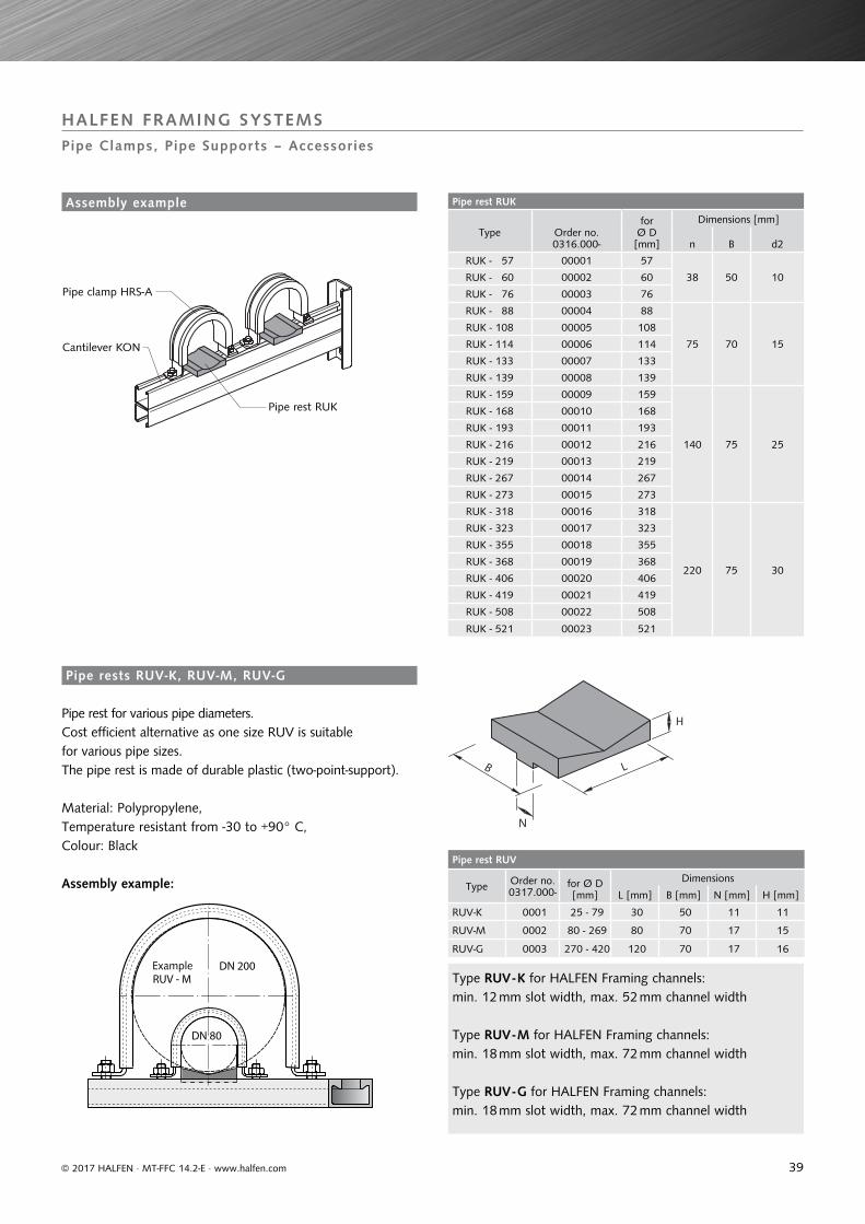
Pipe rest RUK
Type Order no. 0316.000-
for Ø D [mm]
Dimensions [mm]
n B d2
RUK - 57 00001 57
38 50 10RUK - 60 00002 60
RUK - 76 00003 76
RUK - 88 00004 88
75 70 15
RUK - 108 00005 108
RUK - 114 00006 114
RUK - 133 00007 133
RUK - 139 00008 139
RUK - 159 00009 159
140 75 25
RUK - 168 00010 168
RUK - 193 00011 193
RUK - 216 00012 216
RUK - 219 00013 219
RUK - 267 00014 267
RUK - 273 00015 273
RUK - 318 00016 318
220 75 30
RUK - 323 00017 323
RUK - 355 00018 355
RUK - 368 00019 368
RUK - 406 00020 406
RUK - 419 00021 419
RUK - 508 00022 508
RUK - 521 00023 521
Pipe rest RUV
Type Order no. 0317.000-
for Ø D [mm]
Dimensions
L [mm] B [mm] N [mm] H [mm]
RUV-K 0001 25 - 79 30 50 11 11
RUV-M 0002 80 - 269 80 70 17 15
RUV-G 0003 270 - 420 120 70 17 16
N
H
B L
RUV - M
DN 80
DN 200
© 2017 HALFEN · MT-FFC 14.2-E · www.halfen.com
HALFEN FRAMING SYSTEMSPipe Clamps, Pipe Supports – Accessories
Pipe rest RUK
Cantilever KON
Pipe clamp HRS-A
Pipe rest for various pipe diameters.Cost efficient alternative as one size RUV is suitable for various pipe sizes. The pipe rest is made of durable plastic (two-point-support).
Material: Polypropylene, Temperature resistant from -30 to +90° C, Colour: Black
Assembly example:
Type RUV - K for HALFEN Framing channels: min. 12 mm slot width, max. 52 mm channel width
Type RUV - M for HALFEN Framing channels: min. 18 mm slot width, max. 72 mm channel width
Type RUV - G for HALFEN Framing channels: min. 18 mm slot width, max. 72 mm channel width
Example
Assembly example
Pipe rests RUV-K, RUV-M, RUV-G
40
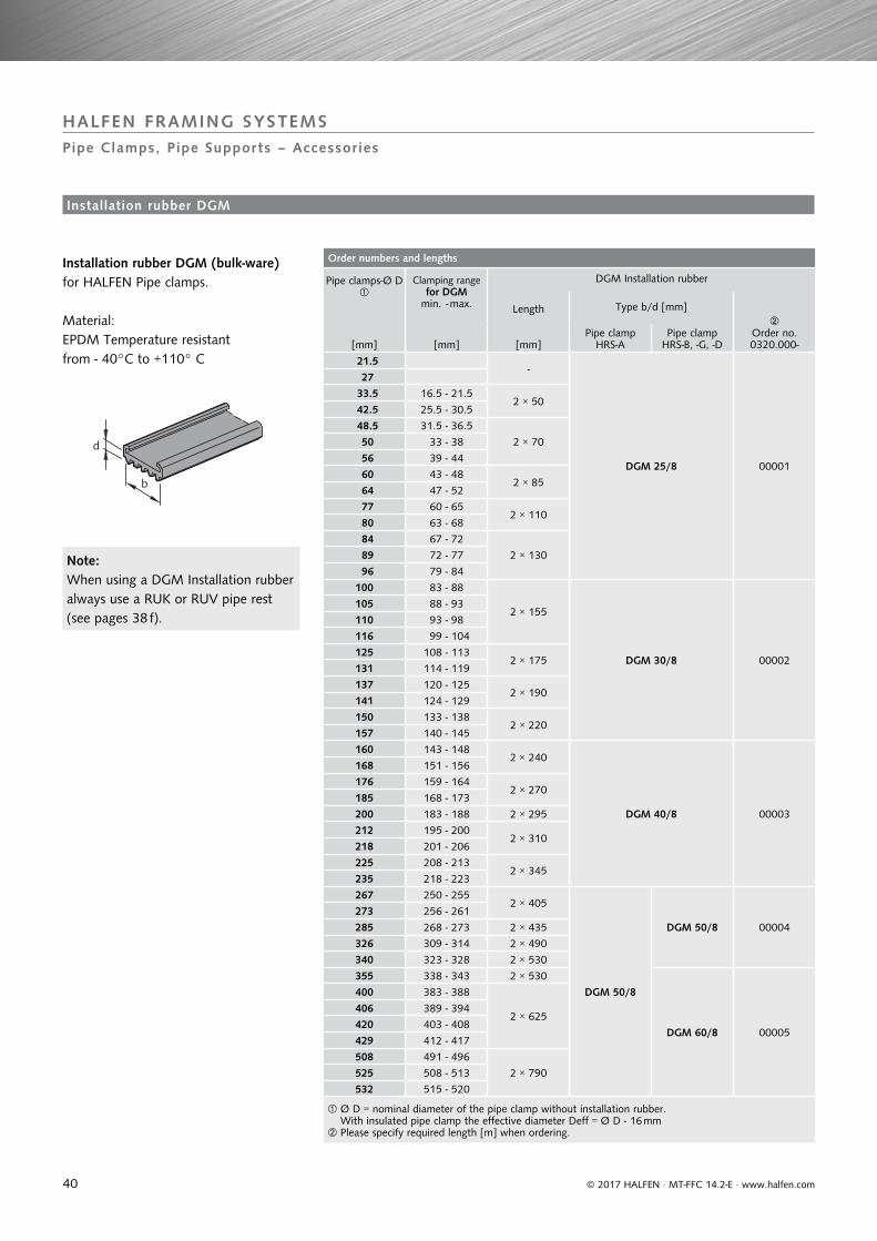
Order numbers and lengths
Pipe clamps-Ø D
Clamping range for DGM
min. - max.
DGM Installation rubber
Length Type b/d [mm]
Order no. 0320.000-[mm] [mm]
Pipe clamp HRS-A
Pipe clamp HRS-B, -G, -D[mm]
21.5 -
DGM 25/8 00001
27 33.5 16.5 - 21.5
2 × 50 42.5 25.5 - 30.5
48.5 31.5 - 36.5
2 × 70 50 33 - 38
56 39 - 44
60 43 - 482 × 85
64 47 - 52
77 60 - 652 × 110
80 63 - 68
84 67 - 72
2 × 130 89 72 - 77
96 79 - 84
100 83 - 88
2 × 155
DGM 30/8 00002
105 88 - 93
110 93 - 98
116 99 - 104
125 108 - 1132 × 175
131 114 - 119
137 120 - 1252 × 190
141 124 - 129
150 133 - 1382 × 220
157 140 - 145
160 143 - 1482 × 240
DGM 40/8 00003
168 151 - 156
176 159 - 1642 × 270
185 168 - 173
200 183 - 188 2 × 295
212 195 - 2002 × 310
218 201 - 206
225 208 - 2132 × 345
235 218 - 223
267 250 - 2552 × 405
DGM 50/8
DGM 50/8 00004
273 256 - 261
285 268 - 273 2 × 435
326 309 - 314 2 × 490
340 323 - 328 2 × 530
355 338 - 343 2 × 530
DGM 60/8 00005
400 383 - 388
2 × 625406 389 - 394
420 403 - 408
429 412 - 417
508 491 - 496
2 × 790525 508 - 513
532 515 - 520
Ø D = nominal diameter of the pipe clamp without installation rubber.With insulated pipe clamp the effective diameter Deff = Ø D - 16 mm
Please specify required length [m] when ordering.
d
b
© 2017 HALFEN · MT-FFC 14.2-E · www.halfen.com
HALFEN FRAMING SYSTEMSPipe Clamps, Pipe Supports – Accessories
Installation rubber DGM (bulk-ware)for HALFEN Pipe clamps.
Material:EPDM Temperature resistant from - 40°C to +110° C
Note:When using a DGM Installation rubber always use a RUK or RUV pipe rest (see pages 38 f).
Installation rubber DGM
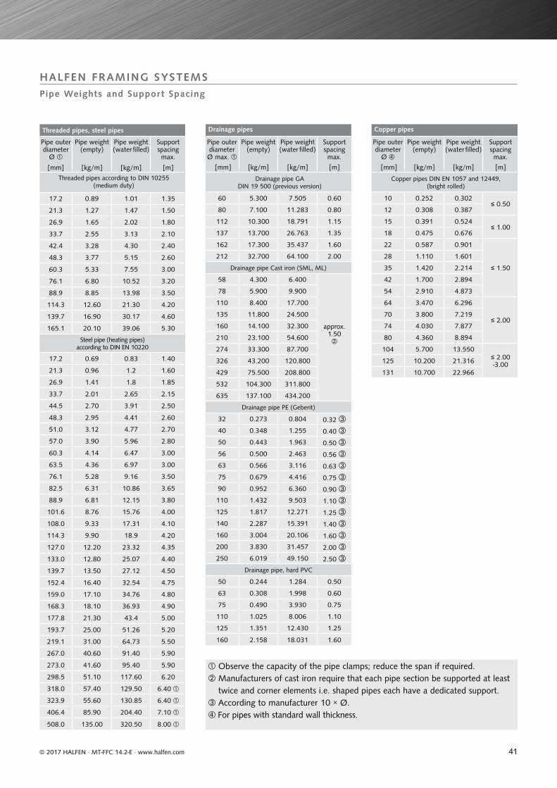
41
Threaded pipes, steel pipes
Pipe outer diameter
Ø
Pipe weight (empty)
Pipe weight (water filled)
Support spacing max.
[mm] [kg/m] [kg/m] [m]
Threaded pipes according to DIN 10255 (medium duty)
17.2 0.89 1.01 1.35
21.3 1.27 1.47 1.50
26.9 1.65 2.02 1.80
33.7 2.55 3.13 2.10
42.4 3.28 4.30 2.40
48.3 3.77 5.15 2.60
60.3 5.33 7.55 3.00
76.1 6.80 10.52 3.20
88.9 8.85 13.98 3.50
114.3 12.60 21.30 4.20
139.7 16.90 30.17 4.60
165.1 20.10 39.06 5.30
Steel pipe (heating pipes) according to DIN EN 10220
17.2 0.69 0.83 1.40
21.3 0.96 1.2 1.60
26.9 1.41 1.8 1.85
33.7 2.01 2.65 2.15
44.5 2.70 3.91 2.50
48.3 2.95 4.41 2.60
51.0 3.12 4.77 2.70
57.0 3.90 5.96 2.80
60.3 4.14 6.47 3.00
63.5 4.36 6.97 3.00
76.1 5.28 9.16 3.50
82.5 6.31 10.86 3.65
88.9 6.81 12.15 3.80
101.6 8.76 15.76 4.00
108.0 9.33 17.31 4.10
114.3 9.90 18.9 4.20
127.0 12.20 23.32 4.35
133.0 12.80 25.07 4.40
139.7 13.50 27.12 4.50
152.4 16.40 32.54 4.75
159.0 17.10 34.76 4.80
168.3 18.10 36.93 4.90
177.8 21.30 43.4 5.00
193.7 25.00 51.26 5.20
219.1 31.00 64.73 5.50
267.0 40.60 91.40 5.90
273.0 41.60 95.40 5.90
298.5 51.10 117.60 6.20
318.0 57.40 129.50 6.40
323.9 55.60 130.85 6.40
406.4 85.90 204.40 7.10
508.0 135.00 320.50 8.00
Drainage pipes
Pipe outer diameter Ø max.
Pipe weight (empty)
Pipe weight (water filled)
Support spacing max.
[mm] [kg/m] [kg/m] [m]
Drainage pipe GA DIN 19 500 (previous version)
60 5.300 7.505 0.60
80 7.100 11.283 0.80
112 10.300 18.791 1.15
137 13.700 26.763 1.35
162 17.300 35.437 1.60
212 32.700 64.100 2.00
Drainage pipe Cast iron (SML, ML)
58 4.300 6.400
approx. 1.50
78 5.900 9.900
110 8.400 17.700
135 11.800 24.500
160 14.100 32.300
210 23.100 54.600
274 33.300 87.700
326 43.200 120.800
429 75.500 208.800
532 104.300 311.800
635 137.100 434.200
Drainage pipe PE (Geberit)
32 0.273 0.804 0.32 40 0.348 1.255 0.40 50 0.443 1.963 0.50 56 0.500 2.463 0.56 63 0.566 3.116 0.63 75 0.679 4.416 0.75 90 0.952 6.360 0.90 110 1.432 9.503 1.10 125 1.817 12.271 1.25 140 2.287 15.391 1.40 160 3.004 20.106 1.60 200 3.830 31.457 2.00 250 6.019 49.150 2.50
Drainage pipe, hard PVC
50 0.244 1.284 0.50
63 0.308 1.998 0.60
75 0.490 3.930 0.75
110 1.025 8.006 1.10
125 1.351 12.430 1.25
160 2.158 18.031 1.60
Copper pipes
Pipe outer diameter
Ø
Pipe weight (empty)
Pipe weight (water filled)
Support spacing max.
[mm] [kg/m] [kg/m] [m]
Copper pipes DIN EN 1057 and 12449, (bright rolled)
10 0.252 0.302≤ 0.50
12 0.308 0.387
15 0.391 0.524≤ 1.00
18 0.475 0.676
22 0.587 0.901
≤ 1.50
28 1.110 1.601
35 1.420 2.214
42 1.700 2.894
54 2.910 4.873
64 3.470 6.296
≤ 2.0070 3.800 7.219
74 4.030 7.877
80 4.360 8.894
104 5.700 13.550≤ 2.00 -3.00125 10.200 21.316
131 10.700 22.966
HALFEN FRAMING SYSTEMSPipe Weights and Support Spacing
© 2017 HALFEN · MT-FFC 14.2-E · www.halfen.com
Observe the capacity of the pipe clamps; reduce the span if required. Manufacturers of cast iron require that each pipe section be supported at least
twice and corner elements i.e. shaped pipes each have a dedicated support. According to manufacturer 10 × Ø.For pipes with standard wall thickness.
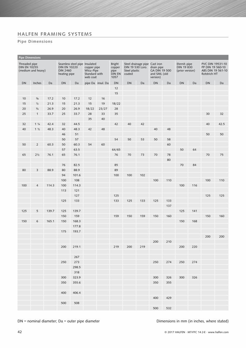
42
Pipe Dimensions
Threaded pipe DIN EN 10255 (medium and heavy)
Seamless steel pipe DIN EN 10220 DIN 2460 heating pipe
Insulated copper pipe Wicu - Pipe Standard with web coat
Bright copper pipe DIN EN 1057
Steel drainage pipe DIN 19 530 Loro. Steel plastic coated
Cast iron drain pipeGA DIN 19 500 and SML (old version)
Eternit - pipe DIN 19 830 (prior version)
PVC DIN 19531-10 PP DIN 19 560-10 ABS DIN 19 561-10 Rotstrich HT
DN Inches Da DN Da pipe Da insul. Da DN DN Da DN Da DN Da DN Da
12
15
10 ⅜ 17.2 10 17.2 12 16
15 ½ 21.3 15 21.3 15 19 18/22
20 ¾ 26.9 20 26.9 18/22 23/27 28
25 1 33.7 25 33.7 28 33 35 30 32
35 40
32 1 ¼ 42.4 32 44.5 42 40 42 40 42.5
40 1 ½ 48.3 40 48.3 42 48 40 48
46 51 50 50
50 57 54 50 53 50 58
50 2 60.3 50 60.3 54 60 60
57 63.5 64/65 50 64
65 2½ 76.1 65 76.1 76 70 73 70 78 70 75
80
76 82.5 85 70 84
80 3 88.9 80 88.9 89
94 101.6 100 100 102
100 108 100 110 100 110
100 4 114.3 100 114.3 100 116
113 121
127 125 125 125
125 133 133 125 133 125 133
137
125 5 139.7 125 139.7 125 141
150 159 159 150 159 150 160 150 160
150 6 165.1 150 168.3 150 168
177.8
175 193.7
200 200
200 210
200 219.1 219 200 219 200 220
267
250 273 250 274 250 274
298.5
318
300 323.9 300 326 300 326
350 355.6 350 355
400 406.4
400 429
500 508
500 532
HALFEN FRAMING SYSTEMSPipe Dimensions
© 2017 HALFEN · MT-FFC 14.2-E · www.halfen.com
DN = nominal diameter; Da = outer pipe diameter Dimensions in mm (in inches, where stated)
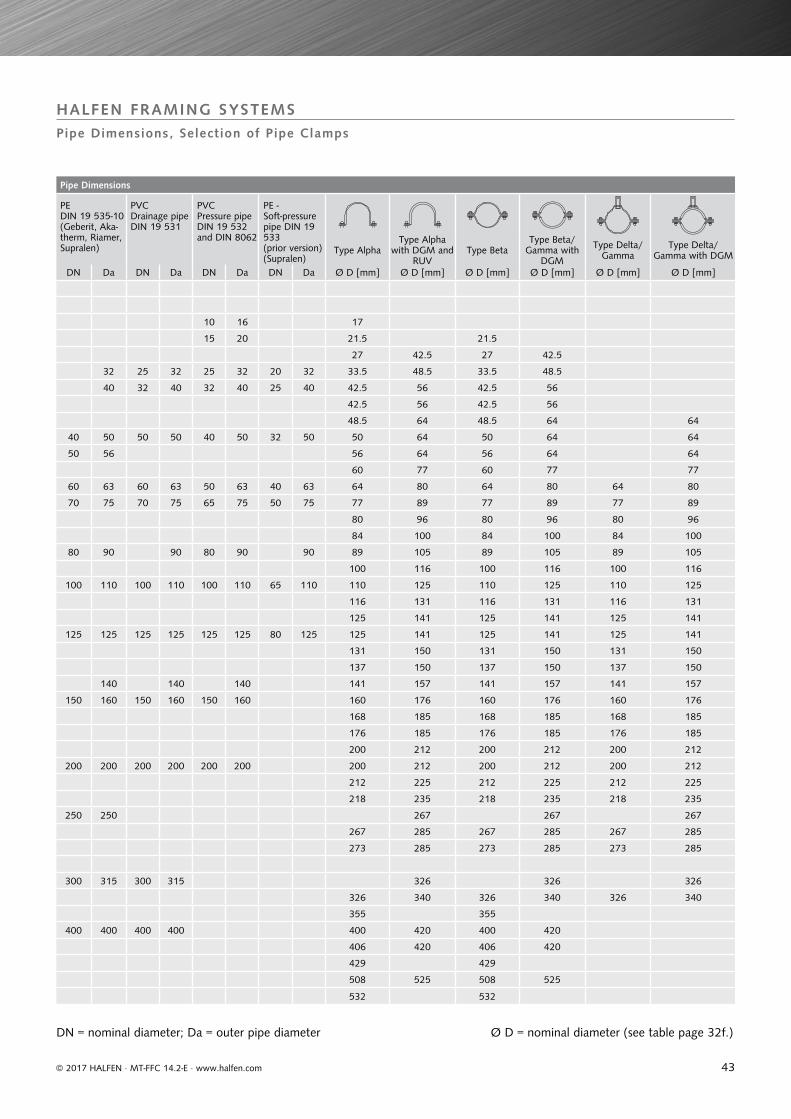
43
Pipe Dimensions
PEDIN 19 535-10 (Geberit, Aka-therm, Riamer, Supralen)
PVC Drainage pipe DIN 19 531
PVC Pressure pipe DIN 19 532 and DIN 8062
PE - Soft-pressure pipe DIN 19 533 (prior version) (Supralen)
Type AlphaType Alpha
with DGM and RUV
Type BetaType Beta/
Gamma with DGM
Type Delta/Gamma
Type Delta/Gamma with DGM
DN Da DN Da DN Da DN Da Ø D [mm] Ø D [mm] Ø D [mm] Ø D [mm] Ø D [mm] Ø D [mm]
10 16 17
15 20 21.5 21.5
27 42.5 27 42.5
32 25 32 25 32 20 32 33.5 48.5 33.5 48.5
40 32 40 32 40 25 40 42.5 56 42.5 56
42.5 56 42.5 56
48.5 64 48.5 64 64
40 50 50 50 40 50 32 50 50 64 50 64 64
50 56 56 64 56 64 64
60 77 60 77 77
60 63 60 63 50 63 40 63 64 80 64 80 64 80
70 75 70 75 65 75 50 75 77 89 77 89 77 89
80 96 80 96 80 96
84 100 84 100 84 100
80 90 90 80 90 90 89 105 89 105 89 105
100 116 100 116 100 116
100 110 100 110 100 110 65 110 110 125 110 125 110 125
116 131 116 131 116 131
125 141 125 141 125 141
125 125 125 125 125 125 80 125 125 141 125 141 125 141
131 150 131 150 131 150
137 150 137 150 137 150
140 140 140 141 157 141 157 141 157
150 160 150 160 150 160 160 176 160 176 160 176
168 185 168 185 168 185
176 185 176 185 176 185
200 212 200 212 200 212
200 200 200 200 200 200 200 212 200 212 200 212
212 225 212 225 212 225
218 235 218 235 218 235
250 250 267 267 267
267 285 267 285 267 285
273 285 273 285 273 285
300 315 300 315 326 326 326
326 340 326 340 326 340
355 355
400 400 400 400 400 420 400 420
406 420 406 420
429 429
508 525 508 525
532 532
HALFEN FRAMING SYSTEMSPipe Dimensions, Selection of Pipe Clamps
© 2017 HALFEN · MT-FFC 14.2-E · www.halfen.com
DN = nominal diameter; Da = outer pipe diameter Ø D = nominal diameter (see table page 32f.)
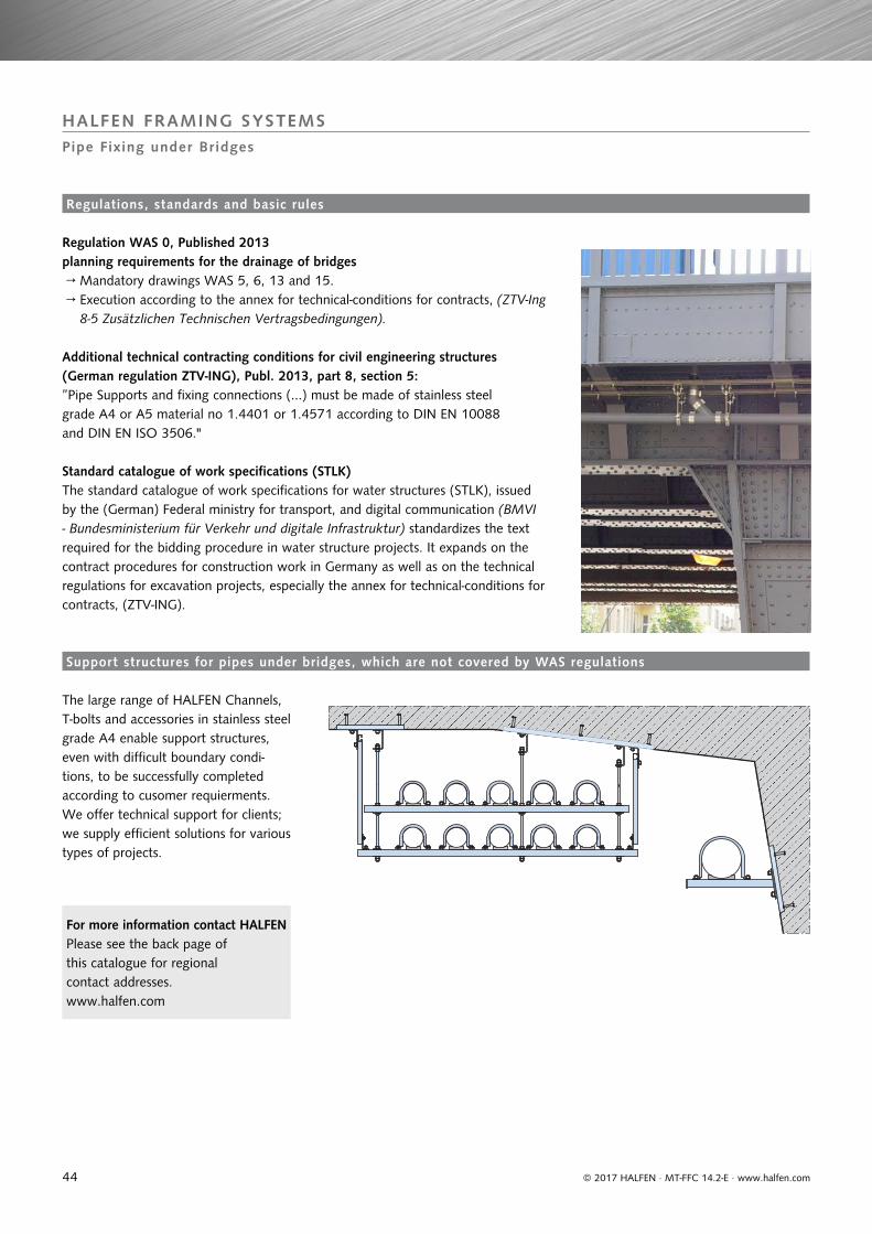
44
HALFEN FRAMING SYSTEMSPipe Fixing under Bridges
© 2017 HALFEN · MT-FFC 14.2-E · www.halfen.com
Regulation WAS 0, Published 2013 planning requirements for the drainage of bridges → Mandatory drawings WAS 5, 6, 13 and 15. → Execution according to the annex for technical-conditions for contracts, (ZTV-Ing
8-5 Zusätzlichen Technischen Vertragsbedingungen).
Additional technical contracting conditions for civil engineering structures (German regulation ZTV-ING), Publ. 2013, part 8, section 5:
Standard catalogue of work specifications (STLK)
”Pipe Supports and fixing connections (...) must be made of stainless steel grade A4 or A5 material no 1.4401 or 1.4571 according to DIN EN 10088 and DIN EN ISO 3506."
The standard catalogue of work specifications for water structures (STLK), issued by the (German) Federal ministry for transport, and digital communication (BMVI - Bundesministerium für Verkehr und digitale Infrastruktur) standardizes the text required for the bidding procedure in water structure projects. It expands on the contract procedures for construction work in Germany as well as on the technical regulations for excavation projects, especially the annex for technical-conditions for contracts, (ZTV-ING).
The large range of HALFEN Channels, T-bolts and accessories in stainless steel grade A4 enable support structures, even with difficult boundary condi-tions, to be successfully completed according to cusomer requierments.We offer technical support for clients; we supply efficient solutions for various types of projects.
Regulations, standards and basic rules
Support structures for pipes under bridges, which are not covered by WAS regulations
For more information contact HALFENPlease see the back page of this catalogue for regionalcontact addresses.www.halfen.com
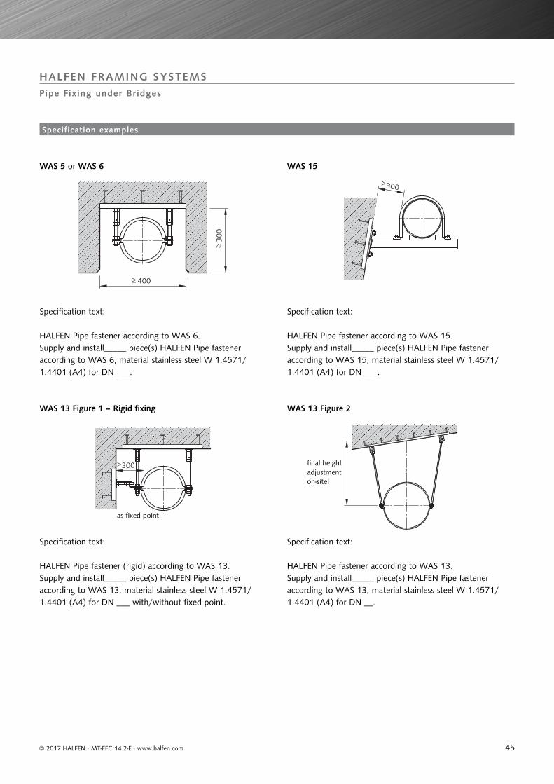
45
HALFEN FRAMING SYSTEMSPipe Fixing under Bridges
300
400
300
300
© 2017 HALFEN · MT-FFC 14.2-E · www.halfen.com
WAS 5 or WAS 6
WAS 13 Figure 1 – Rigid fixing WAS 13 Figure 2
WAS 15
HALFEN Pipe fastener according to WAS 6. Supply and install_____ piece(s) HALFEN Pipe fastener according to WAS 6, material stainless steel W 1.4571/ 1.4401 (A4) for DN ___.
Specification text:
Specification text:
as fixed point
final height adjustment on-site!
Specification text:
Specification text:
HALFEN Pipe fastener according to WAS 15.Supply and install_____ piece(s) HALFEN Pipe fastener according to WAS 15, material stainless steel W 1.4571/ 1.4401 (A4) for DN ___.
HALFEN Pipe fastener (rigid) according to WAS 13.Supply and install_____ piece(s) HALFEN Pipe fastener according to WAS 13, material stainless steel W 1.4571/ 1.4401 (A4) for DN ___ with/without fixed point.
HALFEN Pipe fastener according to WAS 13.Supply and install_____ piece(s) HALFEN Pipe fastener according to WAS 13, material stainless steel W 1.4571/ 1.4401 (A4) for DN __.
Specification examples
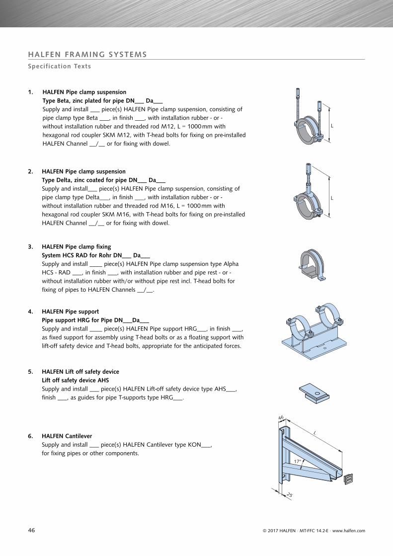
46
HALFEN FRAMING SYSTEMSSpecification Texts
L
L
17°
46
25
L
© 2017 HALFEN · MT-FFC 14.2-E · www.halfen.com
2. HALFEN Pipe clamp suspension Type Delta, zinc coated for pipe DN___ Da___ Supply and install___ piece(s) HALFEN Pipe clamp suspension, consisting of pipe clamp type Delta___, in finish ___, with installation rubber - or - without installation rubber and threaded rod M16, L = 1000 mm with hexagonal rod coupler SKM M16, with T-head bolts for fixing on pre-installed HALFEN Channel __/__ or for fixing with dowel.
3. HALFEN Pipe clamp fixing System HCS RAD for Rohr DN___ Da___ Supply and install ____ piece(s) HALFEN Pipe clamp suspension type Alpha HCS - RAD ___, in finish ___, with installation rubber and pipe rest - or - without installation rubber with/or without pipe rest incl. T-head bolts for fixing of pipes to HALFEN Channels __/__.
4. HALFEN Pipe support Pipe support HRG for Pipe DN___Da___ Supply and install ____ piece(s) HALFEN Pipe support HRG___, in finish ___, as fixed support for assembly using T-head bolts or as a floating support with lift-off safety device and T-head bolts, appropriate for the anticipated forces.
5. HALFEN Lift off safety device Lift off safety device AHS Supply and install ___ piece(s) HALFEN Lift-off safety device type AHS___, finish ___, as guides for pipe T-supports type HRG___.
6. HALFEN Cantilever Supply and install ___ piece(s) HALFEN Cantilever type KON___, for fixing pipes or other components.
1. HALFEN Pipe clamp suspension Type Beta, zinc plated for pipe DN___ Da___
Supply and install ___ piece(s) HALFEN Pipe clamp suspension, consisting of pipe clamp type Beta ___, in finish ___, with installation rubber - or - without installation rubber and threaded rod M12, L = 1000 mm with hexagonal rod coupler SKM M12, with T-head bolts for fixing on pre-installed HALFEN Channel __/__ or for fixing with dowel.
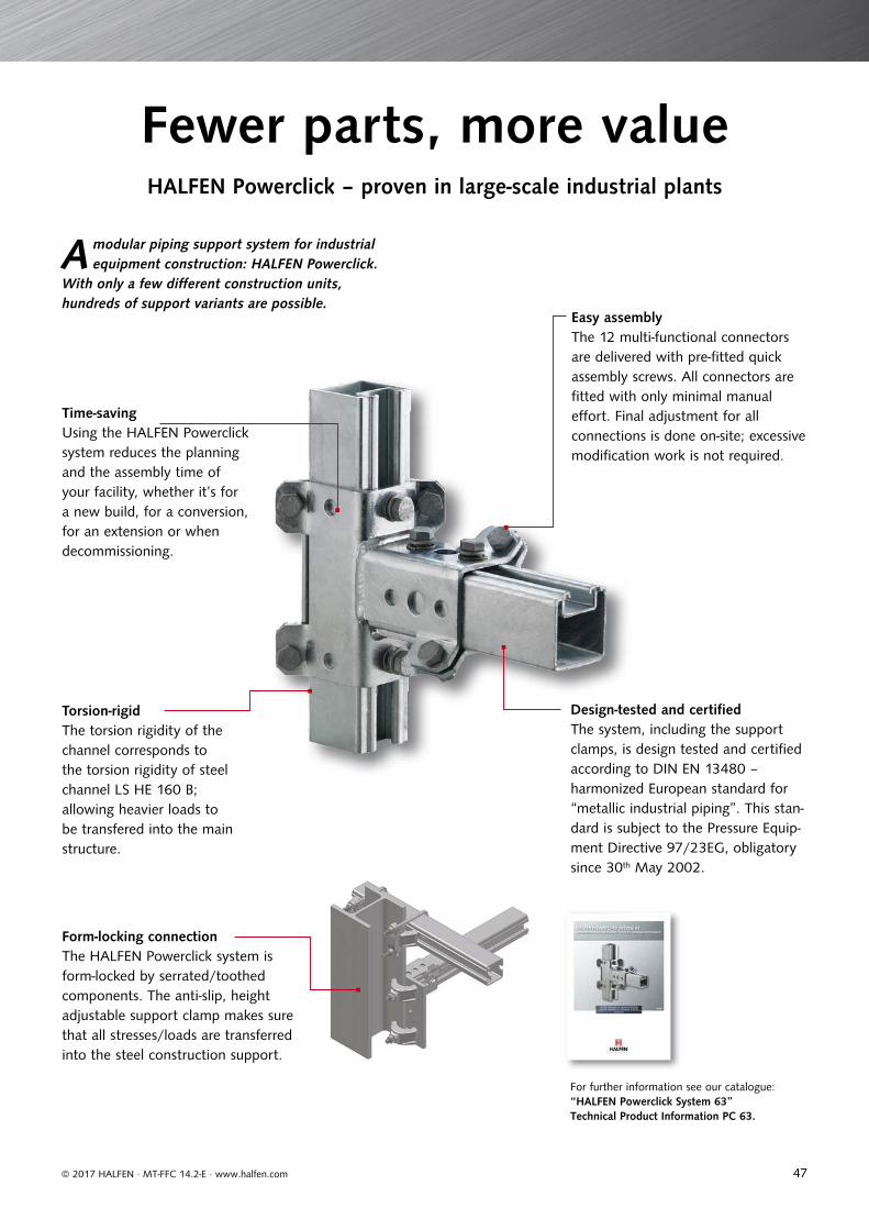
47© 2017 HALFEN · MT-FFC 14.2-E · www.halfen.com
Design-tested and certifi ed The system, including the support clamps, is design tested and certifi ed according to DIN EN 13480 – harmonized European standard for “metallic industrial piping”. This stan-dard is subject to the Pressure Equip-ment Directive 97/23EG, obligatory since 30th May 2002.
Fewer parts, more valueHALFEN Powerclick – proven in large-scale industrial plants
A modular piping support system for industrial equipment construction: HALFEN Powerclick.
With only a few diff erent construction units, hundreds of support variants are possible.
Form-locking connectionThe HALFEN Powerclick system is form-locked by serrated/toothed components. The anti-slip, height adjustable support clamp makes sure that all stresses/loads are transferred into the steel construction support.
Easy assemblyThe 12 multi-functional connectors are delivered with pre-fi tted quick assembly screws. All connectors are fi tted with only minimal manual eff ort. Final adjustment for all connections is done on-site; excessive modifi cation work is not required.
Torsion-rigidThe torsion rigidity of the channel corresponds to the torsion rigidity of steel channel LS HE 160 B;allowing heavier loads to be transfered into the main structure.
Time-saving Using the HALFEN Powerclick system reduces the planning and the assembly time of your facility, whether it’s for a new build, for a conversion, for an extension or when decommissioning.
For further information see our catalogue:“HALFEN Powerclick System 63” Technical Product Information PC 63.
© 2
017
HA
LFEN
Gm
bH, G
erm
any
appl
ies
also
to
copy
ing
in e
xtra
cts.
M -
013
- E -
02/1
7 PD
F 0
4/17
NOTES REGARDING THIS CATALOGUETechnical and design changes reserved. The information in this publication is based on state-of-the-art technology at the time of publication. We reserve the right to make technical and design changes at any time. HALFEN GmbH shall not accept liability for the accuracy of the information in this publication or for any printing errors.
The HALFEN GmbH subsidiaries in Germany, France, the Netherlands, Austria, Poland, Switzerland and the Czech Republic are Quality Management certified according to ISO 9001:2015, Certificate no. 202384-2016-AQ-GER-DAkkS.
HALFEN is represented with sales offices and distributors worldwide. Please contact us: www.halfen.com
Austria HALFEN Gesellschaft m.b.H.Leonard-Bernstein-Str. 101220 Wien
Phone: +43 - 1 - 259 6770 E-Mail: [email protected]: www.halfen.at
Fax: +43 - 1 - 259 - 6770 99
Belgium / Luxembourg HALFEN N.V.Borkelstraat 1312900 Schoten
Phone: +32 - 3 - 658 07 20E-Mail: [email protected]: www.halfen.be
Fax: +32 - 3 - 658 15 33
China HALFEN Construction Accessories Distribution Co.Ltd.Room 601 Tower D, Vantone CentreNo. A6 Chao Yang Men Wai StreetChaoyang District Beijing · P.R. China 100020
Phone: +86 - 10 5907 3200E-Mail: [email protected]: www.halfen.cn
Fax: +86 - 10 5907 3218
Czech Republic HALFEN s.r.o.Business Center ŠafránkovaŠafránkova 1238/1155 00 Praha 5
Phone: +420 - 311 - 690 060E-Mail: [email protected]: www.halfen-deha.cz
Fax: +420 - 235 - 314 308
France HALFEN S.A.S.18, rue Goubet75019 Paris
Phone: +33 - 1 - 445231 00E-Mail: [email protected]: www.halfen.fr
Fax: +33 - 1 - 445231 52
Germany HALFEN Vertriebsgesellschaft mbHLiebigstr. 14 40764 Langenfeld
Phone: +49 - 2173 - 970 - 0E-Mail: [email protected]: www.halfen.de
Fax: +49 - 2173 - 970 225
Italy HALFEN S.r.l. Soc. UnipersonaleVia F.lli Bronzetti N° 2824124 Bergamo
Phone: +39 - 035 - 0760711E-Mail: [email protected]: www.halfen.it
Fax: +39 - 035 - 0760799
Netherlands HALFEN b.v.Oostermaat 37623 CS Borne
Phone: +31 - 74-267 14 49E-Mail: [email protected]: www.halfen.nl
Fax: +31 - 74-267 26 59
Norway HALFEN ASPostboks 20804095 Stavanger
Phone: +47 - 51 82 34 00E-Mail: [email protected]: www.halfen.no
Fax: +47 - 51 82 34 01
Poland HALFEN Sp. z o.o.Ul. Obornicka 28760-691 Poznan
Phone: +48 - 61 - 622 14 14E-Mail: [email protected]: www.halfen.pl
Fax: +48 - 61 - 622 14 15
Spain HALFEN SpainPLAKABETON S.L.Polígono Industrial Santa Ana c/ Ignacio Zuloaga 2028522 Rivas-Vaciamadrid
Phone: +34 916 669 181E-Mail: [email protected]: www.halfen.es
Fax: +34 916 669 661
Sweden Halfen ABVädursgatan 5412 50 Göteborg
Phone: +46 - 31 - 98 58 00E-Mail: [email protected]: www.halfen.se
Fax: +46 - 31 - 98 58 01
Switzerland HALFEN Swiss AGHertistrasse 25 8304 Wallisellen
Phone: +41 - 44 - 849 78 78E-Mail: [email protected]: www.halfen.ch
Fax: +41 - 44 - 849 78 79
United Kingdom /Ireland
HALFEN Ltd.A1/A2 Portland CloseHoughton Regis LU5 5AW
Phone: +44 - 1582 - 47 03 00E-Mail: [email protected]: www.halfen.co.uk
Fax: +44 - 1582 - 47 03 04
United States of America HALFEN USA Inc. PO Box 18687 San Antonio TX 78218
Phone: +1 800.423.91 40E-Mail: [email protected]: www.halfenusa.com
Fax: +1 877.683.4910
For countries not listed HALFEN International
HALFEN International GmbHLiebigstr. 14 40764 Langenfeld / Germany
Phone: +49 - 2173 - 970 - 0 E-Mail: [email protected]: www.halfen.com
Fax: +49 - 2173 - 970 - 849
CONTACT HALFEN WORLDWIDEHALFEN is represented by subsidiaries in the following countries, please contact us!
www.dnvgl.com