Embed Size (px)
Citation preview
622 HALOGENATED FIRE EXTINGUIS HING AGENT SYSTEMS HS-I
Report of Committee on Halogenated Fire Extinguishing Agent Systems
Roll[ H. Jansen, Chairman,
Department of Fire Protection Engineering, Illinois Institute of Technology, Chicago, Illinois 60616
Robert Roos, Secretary. Norris Industries, Fire and Safety Equipment Div., P. O. Box 2750, Newark, N.J. 07114
J. L. Abbott, Factory Mutual Engineering Corporation
George Chamberlain, Federal Aviation Agency
David L. Engibous, The Dow Chemical Company
Charles L. Ford, E. I. duPont de Nemours and Company
S. K. Goodwin, Factory Insurance Associa- tion
G e o r g e J. Grabowsld, Fenwal Incorporated
Norman W. Lemley, U.S. Coast Guard
Alfred J. Miillngton, U.S. Army Tank Automotive Center
William Seofield, Walter Kidde & Co., Inc.
A. Selan, General Fire Extinguisher Corp.
M. R. SuehomEl, Underwriters' Laborato- ries, Inc.
John M. Wolvertun, Department of the Army
R. J. Wright, Underwriters' Laboratories of Canada
Alternates .
M. J. Miller, Factory Mutual Engineering E . E . Williams, Factory Insurance Associa- Corporation (Alternate to J. L. Abbott.) tion (Alternate to S. K. Goodwin.)
ScopE: To develop standards, recommended practices, or manuals on fixed fire ex- tinguishing systems utilizing bromotrifluoromethane and other similar halogenated extin- guishing agents, covering the installation, maintenance, and use of such systems.
This report has been submitted to letter ballot of the Commit- tee which consists of 15 members of whom 13 have voted affirma- tively and 2 ( Geo. Chamberlain and Alfred J. Millington) have not returned ballots as of the date of this report. Mr. Suchomel has objected to the absence of a specific warning on contamination ol loud by discharge of these systems. This omission will be given care]ul consideration at the next meeting of the Committee. Several of the Committee members have made editorial comments whidl will be incorporated into the standard after full Committee consid- eration and prior to the time it is submitted /or official adoption.
The Committee has completed work on a proposed Tentative Standard for Halogenated Fire Extinguishing Agent Systems--Halon 1301. This draft of a major extinguishing system standard, was prepared with only one year of work by the Committee, and we will devote some effort to polishing certain portions of the standard during the forthcoming year. It was the strong feeling of the Com- mittee that we should submit a Tentative Standard for approval at the earliest possible date even though we recognized that certain areas of the standard were not yet technically perfect.
The standard follows the same successful arrangement used
623 IIS--2 H A L O G E N A T E D FIRE E X T I N G U I S H I N G AGENT SYSTEMS
by the Carbon Dioxide and Dry Chemical Committees in the prep- aration of NFPA Standards 12 and 17 respectively. We feel this will make for easier use and adoption. We encourage the study of this proposed Tentative Standard by all concerned and hope that we will get a maximum of feed-back information so that we will be ,Lble to propose a revised text for official adoption at the next NFPA Annual Meeting.
624 INTRODUCTION 12A-5
Proposed Tentative Standard on
Halogenated Fire Extinguishing Agent Sys t ems~ Halon 1301
NFPA No. 12A-T- t968
Introduction
1. Purpose. This Standard is prepared for use and guidance of those charged with the purchasing, designing, installing, testing, in- specting, approving, listing, operating, and maintaining halogenated agent extinguishing systems (Halon 1301), in order that such equipment will function as intended throughout its life.
Pre-engineered systems (packaged systems) consist of system components designed to be installed according to pretested limita- tions as approved or listed by a nationally recognized testing lab- oratory. Pre-engineered systems may incorporate special nozzles, flow rates, methods of application, nozzle placement, pressurization levels, and quantities of agent which may differ from those detailed elsewhere in this Standard since they are designed for very specific hazards. All other requirements of the Standard apply. Pre-engi- neered systems shall be installed to protect hazards within the lim- itations which have been established by the testing laboratories where listed.
2. Scope. This standard contains minimum requirements for halogenated agent fire extinguishing systems. It includes only the necessary essentials to make the Standard workable in the hands of those skilled in this field. Portable halogenated agent extinguishers are covered in NFPA No. 10, Installation of Portable Fire Extin* guishers, and No. 10A, Maintenance and Use of Portable Fire Ex- tinguishers.
Only those skilled in this work are competent to design and install this equipment. It may be necessary for many of those charged with the purchasing, inspecting, testing, approving, operato ing, and maintaining this equipment to consult with an experienced and competent fire protection engineer in order to effectively dis. charge their respective duties.
3. Arrangement. This Standard is arranged as follows: Introduction. Chapter l--General Information and Requirements. Chapter 2--Total Flooding Systems. Chapter 3--Local Application Systems. Appendix---Explanatory.
1 2 A - 6 HALON 1301 SYSTEMS
625
Chapters 1 through 3 constitute the body of the Standard and contain the rules and regulations necessary for properly designing, installing, inspecting, testing, approving, operating, and maintain- ing halogenated agent fire extinguishing systems.
The Appendix contains educational and informative material that will aid in understanding and applying this Standard.
4. Definitions. For purpose of clarification, the following general terms used with special technical meanings in this Standard are de- fined:
APt'ROVED refers to approval by the authority having jurisdic- tion.
A U T H O R I T Y H A V I N G JURISDICTION: The "authority having jurisdiction" is the organization, office, or individual respon- sible for "approving" equipment, an installation, or a procedure.
NOTE: The phrase "authority having jurisdiction" is used in NFPA standards in a broad manner since jurisdictions and "approval" agencies vary as do their responsibilities. Where public safety is. primary, the "authority having jurisdiction" may be a federal, state, local, or other regional department or individual such as a fire chief, fire marshal, chief of a fire prevention bureau, labor department, health department, build- ing official, electrical inspector, or others having statutory authority. For insurance purposes, an insurance inspection department, rating bureau, or other insurance company representative may be the "authority having jurisdiction." In many circumstances the property owner or his delegated agent as- sumes the role of the "authority having jurisdiction"; at government installations, the commanding officer, or a departmental official may be the "authority having jurisdiction."
LISTED refers to the listing for the use intended, of devices and materials that have been examined by and meet the recognized ~tandards of such testing laboratories as the Factory Mutual Engi- neering Corporation, the Underwriters' Laboratories, Inc., and Underwriters' Laboratories of Canada. All equipment shall bear a label or some other identifying mark.
SHALL is intended to indicate requirements.
SHOULD is intended to indicate recommendations or that which is advised but not required.
Other terms used with special technical meaning are defined ~)r explained where they occur in the Standard.
626 GENERAL INFORMATION AND REQUIREMENTS 12A-7
CHAPTER !. GENERAL INFORMATION
AND REQUIREMENTS
1100. General Information.
1110. Scope. Chapter 1 contains general information, and the design and installation requirements for all features that are generally common to all Halon 1301 (bromotrifluoromethane CBrFa) systems.
"1120. Halon 1301. Halon 1301 is a colorless, odorless, electrically nonconductive gas that is an effective medium for ex- tinguishing fires.
1121. According to present knowledge Halon 1301 extin- guishes fires by inhibiting the chemical reaction of fuel and oxygen. The extinguishing effect due to cooling, or dilution of oxygen or fuel vapor concentration, is minor.
1130. Use and Limitations. Halon 1301 fire extinguishing systems are useful within the limits of this Standard in extinguishing fires in specific hazards or equipment, and in occupancies where an electrically nonconductive medium is essential or desirable, where cleanup or other media presents a problem, or where weight vs. extinguishing potential is a factor.
1131. Some of the more important types of hazards and equipment that Halon 1301 systems may satisfactorily protect in- clude:
1. Gaseous and liquid flammable materials.
2. Electrical hazards such as transformers, oil switches and circuit breakers, and rotating equipment.
3. Engines utilizing gasoline and other flammable fuels.
4. Ordinary combustibles such as paper, wood, and textiles.
5. Hazardous solids.
1132. Halon 1301 should not be used to extinguish fires in- volving the following materials:
1. Chemicals containing their own oxygen supply such as cel- lulose nitrate.
2. Reactive metals such as sodium, potassium, magnesium, titanium, zirconium, uranium, and plutonium.
3. Metal hydrides.
12A-8 HALON 1301 SYSTEMS
627
1140, Types of Systems. There are two types of systems recognized in this standard:
Total Flooding Systems. Local Application Systems.
1141. A Total Flooding System consists of a supply of Haion 1301 arranged to discharge into, and fill to the proper con- centration, an enclosed space or enclosure about the hazard.
1142. A Local Application System consists of a supply of Halon 1301 arranged to discharge directly on the burning material.
* 1200. Personnel Safety.
1210. Hazards to Pe~0nnel. The discharge of Halon 1301 may create hazards to personnel-such as oxygen deficiency and toxic decomposition products.
1211. Safety Requirements. in any proposed use of Halon 1301 where there is a possibility that men may be trapped in or enter into atmospheres made hazardous, suitable safeguards shall be provided to ensure prompt evacuation of and to prevent entry into such atmospheres and also to provide means for prompt rescue of any trapped personnel. Such safety items as personnel training, warning signs, discharge alarms, predischarge alarms and breathing apparatus shall be considered.
1220. Electrical Clearances. All system components shall be so located as to maintain standard electrical clearances from live parts. See Appendix A for Table of Clearances.
1300. "Specifications, Plans and Approvals.
1310. Purchasing Specifications. Specifications for Halon 1301 fire extinguishing systems shall be prepared with care under the supervision of a competent engineer and with the advice of the ~uthority having jurisdiction. To ensure a satisfactory system, the following items should be included in the specifications.
1311. The specifications should designate the authority hav- ing jurisdiction and indicate whether plans are required.
1312. The specifications should state that the installation shall conform to this Standard and meet the approval of the author- ity having jurisdiction.
1313. The specifications should include the specific tests that may be required to meet the approval of the authority having juris- diction, and indicate how cost of testing is to be borne.
628 G E N E R A L INFORMATION AND REQUIREMENTS 12A-9
1314. These specifications should require the provision of equipment listed for the use intended.
1320. Plans. Where plans are required, they shall be pre- pared with care under the supervision of a competent engineer and with the advice of the authority having jurisdiction.
1321. These plans shall be drawn to an indicated scale or be suitably dimensioned and shall be made so they can be easily repro- duced.
1322. These plans shall contain sufficient detail to enable the authority having jurisdiction to evaluate the hazard or hazards and to evaluate the effectiveness of the system. The detail on the haz- ards shall include the materials involved in the hazards, the location of the hazards, the enclosure or limits and isolation of the hazards, and the exposures to the hazard.
1323. The detail on the system shall include information and calculations on the amount of Halon 1301; container storage pres- sure; the location and flow rate of each nozzle including equivalent orifice area; the location, size and equivalent lengths of pipe, fittings and hose; and the location and size of the storage facility. Informa- tion shall be submitted pertaining to the location and function of the detection devices, operating devices, auxiliary equipment, and electrical circuitry, if used. Sufficient information shall be indicated to identify properly the apparatus and devices used. Any special features should be adequately explained.
1330. Approval of Plans. Plans and calculations shall be submitted for approval before work starts.
1331. When field conditions necessitate any material change from approved plans, the change must be approved.
1332. When such material changes from approved plans are made, corrected "as installed" plans shall be supplied to the owner and the authority having jurisdiction.
1340. Approval of Installations. The completed system shall be tested by qualified personnel to meet the approval of the au- thority having jurisdiction. These tests shall be adequate to deter- mine that the system has been properly installed and will function as intended. Only listed or approved equipment and devices shall be used in the systems.
1341. Such tests should include a test for tightness up to the selector Valve, and for continuity of piping with free unobstructed flow beyond the selector valve. The labeling of devices with proper designations and instructions shall be checked. Operational tests
12A-10 H A L O N 1301 SYSTEMS
629
~h'ould be conducted on all devices except cylinder valves in multi- ~ylinder systems. Where conditions prevail that make it difficult to determine adequately the system requirements of design, a suitable discharge test or concentration analysis should be made (see 1313).
1400. Operation and Control of Systems.
1410. Methods of Actuation. Systems shall be classified as manual or automatic in accordance with the method of actuation.
1411. A manual system is one which is actuated by a person, although it may have other features that are automatic.
1412. An automatic system is one which is actuated by au- tomatic means. Such systems shall also have means for manual actuation.
1420. Detection of Fires. Fires or conditions likely to pro- duce fire may be detected by visual (human senses) or by auto- matic means.
1421. Reliance on visual detection may be used only with permission of the authority having jurisdiction, except in manually actuated systems where fire or conditions likely to produce fire can be readily detected by such means.
1422. Automatic detection shall be by any listed or ap-
p roved method or device that is capable of detecting and indicating eat, flame, smoke, combustible vapors, or an abnormal condition
in the hazard such as process trouble that is likely to produce fire.
1423. An adequate and reliable source of energy shall be used in detection systems.
1430. AUTOMATIC DETECTION AND OPERATION IS RECOMMENDED.
1440. Operating Devices. Operating devices include Halon 1301 releasing devices or valves, discharge controls, and shutdown equipment, all of which are necessary for successful performance of the system.
1441. Operation shall be by listed or approved mechanical, electrical, or pneumatic means. An adequate and reliable source of energy shall be used.
1442. All devices shall be designed for the service they will encounter and shall not be readily rendered inoperative or suscepti- ble to accidental operation. Devices shall be normally designed to
630 GENERAL INFORMATION AND REQUIREMENTS 12A-I 1
function properly from - 2 0 ~ to 150~ or marked to indicate tem- perature limitations.
1443. All devices shall be located, installed, or suitably pro- tected so that they are not subject to mechanical, chemical, or other damage which would render them inoperative.
1444. The normal manual control for actuation shall be lo- cated so as to be conveniently and easily accessible at all times in- cluding the time of fire. This control shall cause the complete sys- tem to operate in its normal fashion.
1445. All automatically operated valves controlling the re. lease and distribution shall be provided with approved independent means for emergency manual operation. If the means for manual actuation of the system required in 1422 provides approved posio rive operation independent of the automatic actuation, it may be used as an emergency means. The emergency means, preferabl) mechanical, shall be easily accessible and located close to the valve~ controlled. If possib!e, the system should be designed so tirol emergency actuation can be accomplished from one location. TIII~ does not require an emergency manual control on "reserve" con tainers to be connected to the selector valves.
1446. Manua~ controls shall not require a pull of more th~ 40 pounds (force) nor a movement of more than 14 inches to sr cure operation.
1447. Where gas pressure from system supply containers t~ used as a means for releasing remaining containers and the supp!~ consists of three or more containers, not less than two containel~ shall be used for such operation.
1448. All devices for shutting down supplementary equll ~ ment shall be considered integral parts of the system" and shl,,'l function with the system operation.
1449. All manual operating devices shall be identified ;i.~ the hazard they protect.
1450. Supervision. Supervision of automatic systems is ~15 visable where the possible loss because of any delay in actuati~ may be high and/or where the detection or control systems are �9 extensive and complex that they cannot be readily checked by ~" ual or other inspection. When supervision is provided it should ['~ so arranged that there will be immediate indication of failure. 'lL extent and type of supervision shall be approved by the authof~ having jurisdiction.
IZA-12 XALON 1301 SYSTEMS 631
1460. Operating Alarms and Indicators. Alarms and/or indi- ~k~tors may be needed to indicate the operation of a system, hazards f~ personnel, or failure of any supervised device or equipment. ',!lch devices should be of such a type and should be provided in l lch numbers and at such locations as are necessary to accomplish ~tisfactorily their purpose subject to approval of the authority hav- "1~ jurisdiction. They may be audible, visual, or olfactory.
1461. A positive alarm or indicator should be provided to /~,ow that the system has operated.
1462. An-alarm should be provided to indicate the opera- ,,~n of automatic systems in case an immediate personnel response
desired.
1463. Alarms should be provided to give positive warning of discharge where hazard to personnel may exist. Such alarms
.~,ould function to warn against personnel entry into hazardous c leas as long as such hazards exist or until such hazards are prop- ely recognized (see 1200).
1464. Alarms indicating failure of supervised devices or ~uipment shall give prompt and positive indication of any failure '.tl shall be distinctive from alarms indicating operation or hazard- ~a conditions.
500. Halon 1301Supply.
ISl0. Quantifies. The amount of Halon 1301 in the system '~11 be at least sufficient for the largest single hazard protected or ~up of hazards which are to be protected simultaneously.
1511. Where uninterrupted protection is required, the re- lye quantity shall be a s many multiples of these minimum ,~unts as the authority having jurisdiction considers necessary.
1512. Both primary and reserve supplies for fixed storage ' ,11 be permanently connected to the piping and arranged for easy ' ~llgcover, except where the authority having jurisdiction permits ~ ~mconnected reserve.
1520. Quality. The Halon 1301 quality shall comply with ', (iovernment Specification MIL-M- 12218.
|~30. Replenishment. The time needed to obtain Halon II for replenishment to restore systems to operating condition '1 he considered as a major factor in determining the reserve ,i,l~' needed.
i541). Storage Container Arrangement. Storage containers
632 GENERAL INFORMATION AND REQUIREMENTS lZA-I~
and accessories shall be so located and arranged that inspectio,~, testing, recharging and other maintenance is facilitated and inter. ruption to protection is held to a minimum.
1541. Storage containers shall be located as near as possiblr to the hazard or hazards they protect, but they should not be Io.- cated where they will be exposed to a fire or explosion in these hazards.
1542. Storage containers should not be located so as to Ix' subject to severe weather conditions or be subject to mechanic~d0 chemical, or other damage.
1543. When excessive climatic or mechanical exposures are expected, suitable guards or enclosures shall be provided.
"1550. Storage Containers. The Halon 1301 supply shall Ix" stored in containers designed to hold Halon 1301 in liquefied form at atmospheric temperatures.
Containers shall be charged to a filling density between 50 I~ 75 pounds per cubic feet and super-pressurized with dry nitrogen to 600 psig ---+ 5%, or 360 psig ----- 5% total pressure at 70~ Con~ tainers shall be distinctively and permanently marked with the tylx" and quantity of agent contained therein, together with the degree of super-pressurization.
1551. The Halon 1301 containers used in these system~ shall be designed for use at minimum'working pressures of 380 psi 8 or 630 psig at 70~ and shall meet the requirements of a nationally recognized testing laboratory. The containers shall also meet the U.S. Department of Transportation or the Canadian Board of Transport Commissioners* requirements if used as shipping con- tainers. If not a shipping container, it shall be constructed, tested~ and marked in accordance with Section 8 of the ASME Unfired Pressure Vessels Code; independent inspection and certification is recommended.
1552. A reliable means of indication, other than weighing, shall be provided to determine the pressurization level of refillable containers.
*Sec. 78.36 and 78.37 of Title 49, Transportation, Code of Federal Regula. tions. Parts 71-78. Available from the Superintendent of Documents, U.S. Government Printing Office, Washington, D.C. 20401. 601 pages. In Canada the corresponding information is set forth in the "Board of Transport Com. missioners of Canada Regulations Governing the Transportation of Dan. gerous Articles by Rail" available from the Queen's Printer, Ottawa, Ontario, at a cost of $6.00.
01A-14 HALON 1301 SYSTEMS
633
1553. Charged containers shall be tested for tightness before ,3ipment in accordance with an approved procedure. Shipping ,retainers in service shall be hydrostatically retested for continuing
~zrvice at least every 12 years in accordance with the test procedure ~(I apparatus set forth in the regulations of the U.S. Department of ~'ransportation or Board of Transport Commissioners.
1554. When manifolded, containers shall be adequately ~ ~ounted and suitably supported in a rack provided for the purpose f including facilities for convenient individual servicing or content
,~eighings. Automatic means shall be provided to prevent the loss from the manifold if the system is operated when any containers are ~emoved for maintenance.
1555. Each system shall have a permanent nameplate speci- ~y!ng the number, filling weight, and pressurization level of the con- I.uners.
1556. Only interchangeable containers of one selected size ~hall be manifolded within a system to prbvide the required total ~upply.
1557. Storage temperatures shall not exceed 150~ nor be Iess than -20~ unless the system is designed for proper operation with storage temperatures outside of this range (see 3421 for addi- tional limitations on local application systems). External heating or ~ooling may be used to keep the temperature within this range. When special container charges are used, the containers shall be ~ppropriately marked.
1600. Distribution Systems.
1610. Piping. Piping shall be noncombustible and shall with- ~tand the expected temperatures without detrimental deformation. Iron or steel pipe and fittings preferably should be galvanized inside and out. Copper or brass pipe or tubing may be used without addi- tional corrosion protection. Black steel or ductile iron pipe may be used in noncorrosive atmospheres. Special corrosion-resistant ma- terials or coatings may be required in severely corrosive atmos- pheres.
16 l 1. Ordinary cast iron pipe and fittings shall not be used.
1612. Welded joints, screwed or flanged fittings (malleable iron, steel, or ductile iron) should be used. Suitable flared or com- pression type fittings shall be used with copper or brass tubing.
1620. Arrangement and Installation of Piping and Fittings. Piping shall be installed in accordance with good commercial prac-
634 G E N E R A L INFORMATION AND REQUIREMENTS 1 2 A - I ~,
tices. Care shall be taken to avoid possible restrictions due to fo! eign matter or faulty fabrication or improper installation.
1621. The piping system shall be securely supported will~ due allowance for expansion and contraction and shall not be sub ject to mechanical, chemical, or other damage. Where explosiom, are possible, the piping system shall be hung from supports that ~rc least likely to be displaced.
1622. Pipe shall be reamed and cleaned before assembly and after assembly the entire piping system shall be blown out be fore nozzles or discharge devices are installed.
1623. In systems where valve arrangement introduces set' tions of closed piping, such sections shall be equipped with pressurv relief devices or the valves shall be designed to prevent entrapmenl of liquid. Where pressure-operated container valves are used, ~ means shall be provided to vent any container leakage from thf manifold but which will prevent loss of the agent when the system operates.
1624. All pressure relief devices shall be of such design and so located that the discharge therefrom will not injure personnel 0! be otherwise objectionable.
1630. Valves. All valves shall be suitable for the intended use, particularly in regard to flow capacity and operation. The) shall be used only under temperatures and other conditions fo! which they are listed.
1631. Valves shall be protected against mechanical, cbemb cal, or other damage.
1632. Valves shall be rated for equivalent length in terms ot the pipe or tubing sizes with which they will be used. The equivalent length of container valves shall include siphon tube, valve, dis~ charge head and flexible connector.
1640. Discharge Nozz le s . Discharge nozzles shall be listed for the use intended and for discharge characteristics. Thc discharge nozzle consists of the orifice and any associated horn, shield, or baffle.
1641. Discharge orifices shall be of corrosion-resistanl metal.
1642. Discharge nozzles used in local application systems should be so connected and supported that they may not readily be put out of alignment.
1643. Discharge nozzles shall be permanently marked to
l 'aA~16 HALON 1301 SYSTEMS
635
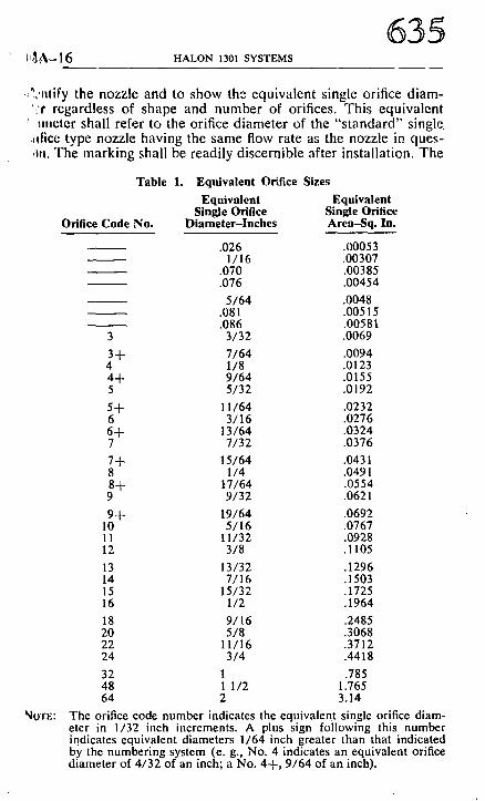
,?,,nlify the nozzle and to show the equivalent single orifice diam- *;r regardless of shape and number of orifices. This equivalent
' mlcter shall refer to the orifice diameter of the "s tandard" single .idlce type nozzle having the same flow rate as the nozzle in ques- ,~n. The marking shall be readily discernible after installation. The
Table 1. Equivalent Orifice Sizes
Orifice Code No.
Equivalent Equivalent Single Orifice Single Orifice
Diameter-Inches Area-Sq. In.
.026 .00053 1/16 .00307
.070 .00385
.076 .00454 5/64 .0048
.081 .00515
.086 .00581 3 3/32 .0069 3+ 7/64 .0094 4 1/8 .0123 4-+- 9/64 .0155 5 5/32 .0192 5+ 11/64 .0232 6 3/16 .0276 6+ 13/64 .0324 7 7/32 .0376 7+ 15/64 .0431 8 1/4 .0491 8-+- 17/64 .0554 9 9/32 .0621 9+ 19/64 .0692
10 5/16 .0767 I1 11/32 .0928 12 3/8 .1105 13 13/32 .1296 14 7/16 .1503 15 15/32 .1725 16 1/2 .1964 18 9/16 .2485 20 5/8 .3068 22 11/16 .3712 24 3/4 .4418
32 1 .785 48 1 1/2 1.765 64 2 3.14
~O'rE: The orifice code number indicates the equivalent single orifice diam- eter in 1/32 inch increments. A plus sign following this number indicates equivalent diameters 1/64 inch greater than that indicated by the numbering system (e. g., No. 4 indicates an equivalent orifice diameter of 4/32 of an inch; a No. 4+, 9/64 of an inch).
636 GENERAL INFORMATION AND REQUIREMENTS 12A-17
"standard" orifice is an orifice having a rounded entry with coefli* cient of discharge not less than 0.98 and flow characteristics :IS given in Table 2. For equivalent orifice diameters, the code given in Table 1 may be used.
1644. Discharge nozzles shall be provided with frangible discs or blow-out caps where clogging, by foreign materials is likely, These devices shall provide an unobstructed opening upon system operation.
I - 0 0 L~
n" W O_
n ' I
n 0 r r
I l l IT
tO O0 b-I n- O-
I 0 0
I 0
1.0,
0.1
0.01 -
0 .001 I_
0.1
F
1 I '
r'---
,/
Z.
_#- 1 _
1.0
H A L O N 1 3 0 1
Q I
I 0 I 0 0 I0(~ .
F L O W - P O U N D S P E R S E C O N D
Fig. 1. Pressure drop vs. flow in steel pipe.
IZA-18 XALON 1301 SYSTEMS s
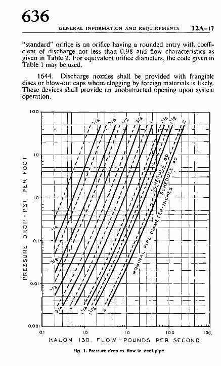
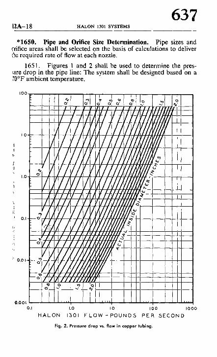
"1650. Pipe and Orifice Size Determination. Pipe sizes and ('rifice areas shall be selected on the basis of calculations to deliver I~e required rate of flow at each nozzle.
1651. Figures 1 and 2 shall be used to determine the pres- ,ure drop in the pipe line: The system shall be designed based on a ?,0~ ambient temperature.
I00
| ,o~ /
o.,i ii}i 0,001 . . . . .
0,1
H A L O N
I / I '~1, lYl, '/g, / I / / ,
I I / I
/ / / /z '///~
,~, ' 1.0
1 3 0 i
I I
o'1 I o o o" I o ' / r ~, i / i / I J,/dLl///~ I i / ] i l t I / l , ' i l l I i f / l , I / I /H/L; / / / I / l lkl '/L/1/1///'/,
I//11It11////~. /YE////////? ,?///!...~...ot l ~ /I,./A/,l//i/~ I /1/IN ~///// I l l
I 0
F 1 0 W - P O U N D 5
l l l l I I I l l l l l l t l l ~ '_/!II!!//11 /lli'llll I '//t'///
i
t O O I 0 0 0
P E R 5 E C O N D
Fig. 2. Pressure drop vs. f low in copper tubing.
638 GENERAL INFORMATION AND REQUIREMENTS 1 2 A - l ~
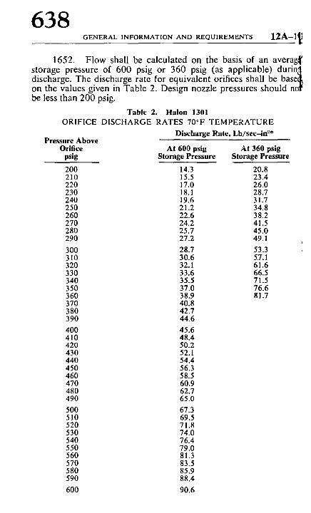
1652. Flow shall be calculated on the basis of an averag~ storage pressure of 600 psig or 360 psig (as applicable) durin~l discharge. The discharge rate for equivalent orifices shall be baset~ on the values given in Table 2. Design nozzle pressures should nr be less than 200 psig.
Table 2. Halon 1301 ORIFICE DISCHARGE RATES 70*F TEMPERATURE
Discharge Rate, Lb/sec-in-"* Pressure Above
Orifice At 600 psig At 360 psig psig Storage Pressure Storage Pressure
200 14.3 210 15.5 220 17.0 230 18.1 240 19.6 250 21.2 260 22.6 270 24.2 280 25.7 290 27.2
300 28.7 310 30.6 320 32.1 330 33.6 340 35.5 350 37.0 360 38.9 370 40.8 380 42.7 390 44.6 400 45.6 410 48.4 420 50.2 430 52.1 440 54.4 450 56.3 460 58.5 470 60.9 480 62.7 490 65.0 500 67.3 510 69.5 520 71.8 530 74.0 540 76.4 550 79.0 560 81.3 570 83.5 580 85.9 590 88.4 600 90.6
20.8 23.4 26.0 28.7 31.7 34.8 38.2 41.5 45.0 49.1
53.3 5.7.1 61.6 66.5 71.5 76.6 81.7
t A - 2 0 HALON 1301 SYSTEMS
639
TOO. Inspection, Maintenance and Instructions.
1710. Inspection and Tests. At least annually, all systems tall be thoroughly inspected and tested for I~/oper operation by a )mpetent inspector. Regular service contracts with the manufac- xer or installing company axe recommended.
1711. The goal of this inspection and testing shall be not aly to ensure that the system is in full operating condition but tail indicate the probable continuance of that condition until the ~xt inspection.
1712. Suitable discharge tests shall be made when inspec- :on indicates their advisability.
1713. The inspection report with recommendations shall be led with the owner.
', 1714. Between the regular service contract inspection or 'zts, the system shall be inspected visually or otherwise by com- jetent personnel, following an approved schedule and procedure.
i' 1715. At least semiannually, the weight and pressure of re- ' liable containers shall be checked. If a container shows a loss in
~t weight of more than 5 percent or a loss in pressure (adjusted )r temperature) of more than 10 percent, it shall be refilled or re- !aced.
1716. Factory charged nonrefillable containers which do not ~ve a means of pressure indication shall be weighed at least semi- anually. If a container shows a loss in net weight of more than 5 ~rcent, it shall be replaced.
1717. The weight and pressure of the container shall be re- .~rded on a tag attached to the container.
t720. Maintenance. These systems shall be maintained in )11 operating condition at all times. Use, impairment, and restora- .on of this protection should be reported promptly to the authority .wing jurisdiction.
1721. Any troubles or impairments shall be corrected at ace by competent personnel.
1730. Instruction. All persons who may be expected to in- .pect, test, maintain, or operate fire extinguishing systems shall be '~oroughly trained and kept thoroughly trained in the functions aey are expected to perform.
640 TOTAL FLOODING SYSTEMS 12A-~
CHAPTER 2. TOTAL FLOODING SYSTEMS
"2100. General Information.
2110. Uses. This type of system may be used where there is fixed enclosure about the hazard that is adequate to enable the rt quired concentration to be built up and maintained for the rt quired period of time to ensure the effective extinguishment of th fire in the specific combustible materials involved.
2111. Total flooding systems provide fire protection withl rooms, vaults, enclosed machines, ovens, containers, storage tank and bins.
2120. General Requirements. Total flooding systems sha' be designed, installed, tested and maintained in accordance wil ~ the applicable requirements in Chapter 1 and with the addition~ requirements set forth in this chapter.
2200. Hazard Specifications.
2210. Types of Fires. Fires which can be extinguished b total flooding methods may be divided into three categoric' namely, (1) surface fires involving flammable liquids or solids; (~ gas fires; and (3) deep-seated fires such as can occur with Class/~ materials subject to spontaneous heating, smoldering and high he~ retention.
2211. Surface fires and gas fires are subject to prompt extin guishment when Halon 1301 is quickly introduced into the enclo sure in sufficient quantity to provide an extinguishing concentra tion for the particular materials involved. NFPA No. 69, Inertin~ for Fire and Explosion Prevention should be referred to when the possibility of flammable concentrations from gas leakage dictate: explosion protection techniques.
2212. For deep-seated fires, the required extinguishing col~ centration shall be maintained for a sufficient period of time to al low the material to cool so that re-ignition will not occur when tht inert atmosphere is dissipated. The hazard should be inspected a, soon as possible thereafter to make certain that extinguishment i, complete.
2220. Enclosure. In the design of total flooding systems, tin characteristics of the enclosure must be considered as follows:
"2221. For all three types of fires, the area of unclosabh openings shall be kept to a minimum. These openings shall be corn pensated for by additional quantities of agent according to th,~ design procedures outlined in the Appendix. The authority havin~
i2A-22 HALON 1301 SYSTEMS
641
:lrisdiction may require tests to assure proper performance as de- !ned by this standard.
2222. To prevent fire from spreading through openings to ,tdjacent hazards or work areas and to make up for leakage of the :~ent, openings shall be compensated for with automatic closures, ~r nozzles or additional agent, and shall be arranged to op- erate simultaneously with system discharge. The agent required by ~ereening nozzles shall be in addition to the normal requirement for C0tal flooding. Where reasonable confinement of agent is imprac- Citable, protection shall be extended to include the adjacent hazards ~r work areas.
2223. For deep-seated fires only, where forced air ventilat- tng systems are involved, they shall be preferably shut down and/or 0osed before or simultaneously with the start of agent discharge; r additional compensating gas shall be provided. Refer to Appen- dix A-2220.
~2300. Halon 1 3 0 1 Requirements for Surface Fires.
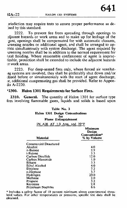
2310 . General. The quantity of Halon 1301 for surface type [ires involving flammable gases, liquids and solids is based upon
Table No. 3 Halon 1301 Design Concentrations
for Flame Extinguishment
IN AIR AT 1.0 Atm. and 70*F
Material
Minimum Design
Concentration* % by Volume
Commercial Denatured Alcohol 4.0 n-Butane 2.9 i-Butane 3.3 Carbon Disulfide 12.0 Carbon Monoxide 1.0 Ethane 3.3 Ethyl Alcohol 4.0 Ethylene 7.2 n-Heptane 3.7 Hydrogen 20.0 Methane 2.0 Propane 3.2 Kerosene 2.8 Petroleum Naphtha 6.6
* Includes a safety factor of 10 percent minimum above experimental thres- hold values. For other temperatures or pressures, specific test data shall be obtained.
642 TOTAL F L O O D I N G SYSTEMS 12A-2.~
normal conditions with the extinguishing system meeting the re quirements specified herein.
2320. Flammable Materials. In the determination of the de sign concentration of Halon 1301, proper consideration shall I~ given to the type and quantity of flammable material involved, th~ conditions under which it normally exists in the hazard, and an} special conditions of the hazard itself. For a particular fuel, twi minimum levels of Halon 1301 concentration may be used: eithe~ is permitted for situations where only flame extinguishment is re quired; the higher level of concentration shall be used where corn plete inerting is required to prevent a subsequent reflash or possi ble explosion.
Appendix A-2300 contains additional guidelines for determin ing the concentration level which should be selected for a p;u ticular hazard.
2321. Flame Extinguishment Data. Table No. 3 gives thi minimum design concentration required to extinguish normal fire,, involving certain flammable gases and liquids at atmospheric pres sure. These values are permitted if it can be shown that a probabl~" explosive atmosphere cannot exist in the hazard as a result of th'. fire. An explosion potential is improbable when:
(a) The quantity of fuel permitted in the enclosmc is less than that required to develop a maximum concentrati0,~ equal to one-half of the lower flammable limit. Additional informll tion is given in Appendix A-2200.
(b) The volatility of the fuel before the fire is to~.~ low to reach the lower flammable limit in air (maximum ambiell~ temperature or fuel temperature does not exceed the closed cul~ flash point temperature), and fire may be expected to burn le~ than 30 seconds before extinguishment.
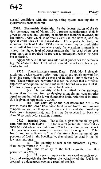
2322. Inerting Data. Table No. 4 gives flammability peal data obtained with Halon 1301 for several materials. These valuc~ shall be used when the conditions of 2321 are not or cannot be me! The concentrations shown are greater than those given in Tabl', No. 3, and are sufficient to "inert" the atmosphere against all pn~ portions of fuel in air. Specifically, they should be used in the h~! lowing situations:
(a) The quantity of fuel in the enclosure is grealc~ than that permitted in 2321 (a).
(b) The volatilfty of the fuel is greater than thI:~ permitted in 2321(b).
(c) The system response is not rapid enough to de tect and extinguish the fire before the volatility of the fuel is h| creased to a dangerous level as a result of the fire.
~2A-24 HALON 1301 SYSTEMS
643 Table No. 4
Halon 1301 Design Concentrations for
Inerting IN AIR AT 1.0 Atm. and 70~
Material
Minimum Design Concentration*
% by Volume Acetone 5.3 Benzene 4.3 i-Butane 8.0 Carbon Disulfide 12.0 Diethyl Ether 6.3 Ethyl Alcohol 4.0 Ethyl acetate 4.6 Ethylene 11.0 Hydrogen 20.0 n-Heptane 8.0 JP-4 6.6 Methane 2.0 i-Pentane 6.3 Propane 6.5
* For other temperatures or pressures, specific test data shall be obtained.
2323. For materials not given in the above tables, the Halon 0301 design concentration shall be obtained by test of flame ex- tinguishing effectiveness plus a 10 percent minimum safety factor :,r by determination of the inerting concentration.
2324. For combinations of fuels the values for the fuel re- quiring the greatest concentration shall be used.
2325. Where gaseous or highly volatile or atomized fuels ~re expected, additional protective measures such as actuation by l)azardous vapor detectors are recomtnended. NFPA Standard ~/o. 69 covering explosion suppression techniques should also be ~onsulted for such situations.
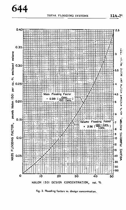
2330. Flooding Factors. Figure 3 gives mass and volume 0,ooding factors for Halon 1301 required to achieve the design con- ,.entration within the enclosure. An allowance is included for nor- ~llal leakage from a "tight" enclosure due to agent expansion. Ad- ~litional quantities of agent shall be provided to compensate for ~mciosable openings or forced ventilation. Appendix A-2220 and ,'~-2431 give further information.
2340. Special Conditions. Additional quantities of Halon !301 shall be provided to compensate for any special conditions ~hat adversely affect the extinguishing efficiency. It shall be the re- sponsibility of the system designer to show that such conditions have been taken into account in the design of a system.
644 TOTAL FLOODING SYSTEMS 12A-2 ' ,
2 o
~D ==, o m
g,
n
:,0
o=,
d o l- t )
t9 Z 13 0 o, It.
O0 u3
0 I0
l i l l l i i : i i J i i , , t , i I I I I ! l l ! l , , , I , , I , . . . . " : , I 1 1 1 1 1 t i I l l L i - ! - i - l - : i I I i l-i-I-t-H-,' ,' l-i- _i_Li_L 4 i , , i I I i 1 7 ~ i l t l I r " ' '
I I ~' ] I i l l l l t l i ,r ~, I . . . . . . . , I , , i i ! i ! ! l ! l , i , i i !
~ 4 - H " l ~ i i ' . i l i II i i i i i i l l H - t - I I l I ; i : ; , ; , ;
, l l i i i i l i , i
" - iiiii',:i
loss Flooding F'actor _ Conc. - 0,;591 ( ~ )
~ 2 1 - + ,~-?- -
i !1~t1!1!
- h - i - t 4 - 1 - 1 - I - i - - ;I-t-I_~.~l-I_~T.l-I-~i_- _
20 30
_! ! l l ~
= Eii -lq- I~
I I I : : i l l
!i ilr i i
!i ;ll i, ill i l l
rl
- I - . + -
_+_+_
4 * - ; /
~"l-- rt--.+--
J Volume FI i = 2 .56
Fig. 3. Flooding factors vs. design concentration.
HALON 1301 DESIGN CONCENTRATIONj vol. % 40 50
( tZA-26 HALON 1301 SYSTEMS
645 ~Z400. Deep-Seated Fires.
2410. General. When Halon 1301 is used for control or ex- nguishment of deep-seated fires, Appendix A-2032 should be con- IItcd before designing a total flooding system for this type of haz-
c;tl.
2420. Considerations. Four factors shall be considered and ~cir effects controlled for optimum extinguishment. These are: 13ent concentration, soaking time, fuel arrangement, and detection t me.
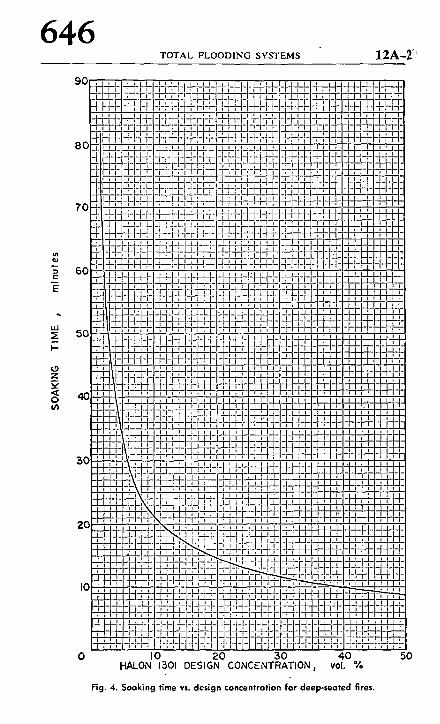
2421. Agent Concentration and Soaking Time. The design ,0ncentration and the soaking time required at that concentration :re given in Figure 4. These values provide a concentration of agent ~hich will slow the combustion rate sufficiently so that the con- I.fined heat can be dissipated to the surroundings within the spe- dried soaking time. To prevent possible re-ignition, the fire site ~hould be inspected prior to reducing the agent concentration to :ssure that extinguishment is complete.
*2422. Fuel Arrangement. The values in Figure 4 are ~alid only for a discontinuous fuel array. In situations in which !he fuel arrangement would tend to prevent heat dissipation, the ~gent concentration and/or soaking time shall be increased.
2423. Detection. Many deep-seated fires can be reduced in ~verity by proper selection of a detection system. A system capable ~ff detecting a fire in its earliest stages is strongly recommended.
2430. Special Conditions.
"2431. Any openings which cannot be closed automatically ~hall require an initial excess or extended discharge in a quantity ~ufficient to maintain the agent concentration above the design level for the entire soaking period.
2432. The cur~,e in Figure 4 shows that the effectiveness in- creases as the agent concentration is increased. Therefore, it is rec- ommended that the highest agent concentration that can be tol- crated from practical considerations be employed.
Z500. Distribution System.
2510. General. The distribution system for applying Halon 1301 to enclosed hazards shall be designed with due consideration for the materials involved, the type of burning expected, and the nature of the enclosure. These factors all may affect the discharge times and rates of application.
646 TOTAL FLOODING SYSTEMS 12A-2",'
uJ
t--
L9 Z
o u~
0 I0 20 30 40 HALON 1301 DESIGN CONCENTRATIONj vol. %
Fig. 4. Soaking time vs. design concentration far deep-seated fires.
50
|2A-28 HALON 1301 SYSTEMS
647 *2520. Rate ol Application. The minimum design rate of ap-
l,~llcation shall be based on the quantity of agent required for the ~sired concentration and the time allotted to achieve the desired oncentration.
2521. The design concentration shall be achieved in 30 c:conds or a shorter period if practicable.
2530. Extended Application Rate. Where leakage is appre- ciable and the design concentration must be obtained quickly and q)aintained for an extended period of time, agent quantities pro- ~ided for leakage compensation may be applied at a reduced rate.
2531. This type of application is particularly suitable to en- 0osed rotating electrical apparatus, such as generators, motors and ~onvertors, and also may be needed for total flooding protection ~)f deep-seated fires.
2532. The design concentration shall be initially obtained within the time limits specified in 2520.
2533. The rate of extended discharge shall be sufficient to maintain the desired concentration for the duration of application.
2540. Piping and Supply. Piping shall be designed in accord- ance with the requirements outlined in Chapter 1 to deliver the re- quired rate of application at each nozzle.
2550. Nozzle Choice and Location. Nozzles used with total Ilooding systems shall be of the type listed for the intended purpose, and shall be located with the geometry of the hazard and enclosure taken into consideration.
2551. The type of nozzles selected, their number, and their placement shall be such that the design concentration will be estab- lished in all parts of the hazard enclosure, and such that the dis- charge will not unduly splash flammable liquids or create dust clouds that might extend the fire, create an explosion, or otherwise adversely affect the contents of the enclosure. Nozzles vary in de- sign and discharge characteristics and shall be selected on the basis of their adequacy for the use intended.
2600. Venting Consideration.
2610. General. Venting of an enclosure may be necessary to relieve pressure build-up due to the discharge of large quantities of Halon 1301. Appropriate pressure relief depends on the injection rate of the Halon 1301 and enclosure strength.
2620. Pressure Relief Venting. Porosity and leakages such as around doors, windows and dampers, though not readily apparent
648 TOTAL FLOODING SYSTEMS 12A-29
or easily calculated, will usually provide sufficient relief for Halon 1301 flooding systems without need for additional venting. Record storage rooms, refrigerated spaces and duct work also generally need no additional venting.
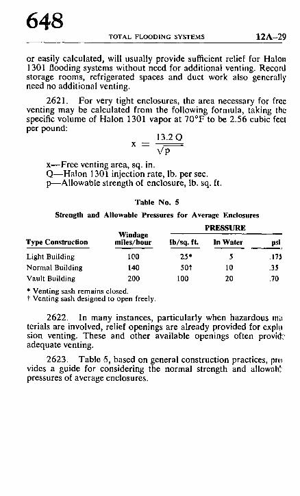
2621. For very tight enclosures, the area necessary for free venting may be calculated from the following formula, taking the specific volume of Halon 1301 vapor at 70~ to be 2.56 cubic feel per pound:
13.2Q X - -
Vp x--Free venting area, sq. in. Q--Halon 1301 injection rate, lb. per see. p---Allowable strength of enclosure, lb. sq. ft.
Table No. 5
Strength and Allowable Pressures for Average Enclosures
PRESSURE Windage
Type Construct ion mi les /hour lb /sq , ft. In Water psi
Light Building 100 25* 5 .175
Normal Building 140 501" 10 .35
Vault Building 200 100 20 .70
* Venting sash remains closed. t Venting sash designed to open freely.
2622. In many instances, particularly when hazardous m~ terials are involved, relief openings are already provided for explo sion venting. These and other available openings often provh|." adequate venting.
2623. Tablo -5, based on general construction practices, pn,~ vides a guide for considering the normal strength and allowah"r pressures of average enclosures.
I 2A-30 HAl .ON 1301 SYSTEMS
649
CH A PTER 3. LOCAL APPLICATION SYSTEMS.
j I00. General Information.
3110. Uses. Local application systems may be used for the extinguishment of surface fires in flammable liquids, gases, and tolids where the hazard is not enclosed or where the enclosure does f~t)t conform to the requirements for total flooding. Where deep- ~cated fires are expected, the requirements of Chapter 2 apply.
3111. Examples of hazards that may be successfully pro- ~'ected by local application systems include dip tanks, quench tanks, q~ray booths, oil filled electric transformers, vapor vents, etc.
3120. General Requirements. Local application systems dlall be designed, installed, tested and maintained in accordance ~vith the applicable requirements of Chapter 1 and with the addi- tional requirements set forth in this chapter.
~200. Hazard Specifications.
3210. Extent of Hazard. The hazard shall be so isolated ~r other hazards or combustibles that fire will not spread outside ~he protected area. The entire hazard shall be protected. The haz- .~r(! shall include all areas that are or may become coated by com- I~ustible liquids or thin solid coatings such as areas subject to ~pillage, leakage, dripping, splashing, or condensation, and all asso- iated materials or equipment such as freshly coated stock, drain
E~ards, hoods, ducts, etc., that might extend fire outside or lead fire , nlo the protected area.
3211. A series of interexposed hazards may be subdivided ~nlo smaller groups or sections with the approval of the authority r~aving jurisdiction. Systems for such hazards shall be designed to rWe immediate independent protection to adjacent groups or sec- ;mls as needed.
3220. Location of Hazard. The hazard may be indoors or /,'3rtly sheltered. If the hazard is-completely out of doors, it is es- :Tntial that the agent discharge be such that winds or strong air cur- ,~'nts do not impair the protection. It shall be the responsibility of ~e system designer to show that such conditions have been taken :lto account in the design of a system.
t300. Halon 1301Requirements.
3310. General. The quantity of agent required for local ap- I lication systems shall be based on liquid discharge only and on the
~|al rate of discharge needed to blanket the area or volume pro-
650 LOCAL A P P L I C A T I O N SYSTEMS 12A-31
tected and the time that the discharge must be maintained to assure complete extinguishment.
331 I. The computed quantity of agent shall be increased by 25 percent to determine nominal container storage capacity since only the liquid portion of the discharge is effective. This increase is not required for the total flooding portion of combined local appli- cation and total flooding systems.
3312. Where long pipelines are involved or where the pip- ing may be exposed to higher than normal temperatures, the sys- tem shall be designed to compensate for liquid vaporized in the piping.
3320. Rate of Discharge. Nozzle discharge rates shall be de- termined as outlined below:
3321. If a part of the hazard is to be protected by total flooding, the discharge rate for the total flooding part shall be com- puted by multiplying the quantity required for total flooding by the factor 0.80 and dividing by the time of the local application dis- charge,
0.80QF To
where RF -- rate of flow for the total flooding portion in pounds per second.
QF "-- total quantity of Halon 1301 for the total flooding portion in pounds.
To ---- liquid discharge time for the local appli- cation portion in seconds.
3322. The minimum design rate (tL3 shall be two times the minimum rate for extinguishment (R,,) independent of time, i.e.,
Ro - - 2 R,.
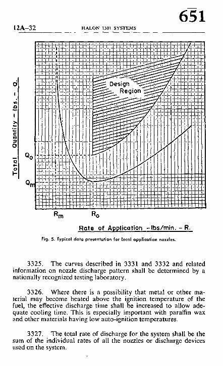
The minimum design quantity (Qo) shall be two times the mini- mum quantity (Q,.) required for extinguishment at any selected design rate. The minimum design time (To) shall be determined by dividing the design quantity (Qo) by the design rate (Ro) (see Figure 5).
3323. The basis for system design for overhead nozzles shall be a family of curves defining the extinguishing parameters of the nozzles at respective heights above the flammable liquid surface in the form shown by.Figure 5.
3324. The basis for system design for tankside nozzles shall be a curve defining the extinguishing parameters of the nozzles in the form shown by Figure 5.
12A-32 HALON 1301 SYSTEMS
R m Ro
Rate of Application - I b s / m i n . - R.
Fig. 5. Typical data presentation for local application nozzles.
3325. The curves described in 3331 and 3332 and related information on nozzle discharge pattern shall be determined by a nationally recognized testing laboratory.
3326. Where there is a possibility that metal or other ma- terial may become heated above the ignition temperature of the fuel, the effective discharge time shall be increased to allow ade- cluate cooling time. This is especially important with paraffin wax and other materials having low auto-ignition temperatures.
3327. The total rate of discharge for the system shall be the sum of the individual rates of all the nozzles or discharge devices used on the system.
652 LOCAL A P P L I C A T I O N SYSTEMS 12A-33
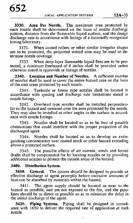
3330. Area Per Nozzle. The maximum area protected by each nozzle shall be determined on the basis of nozzle discharge pattern, distance from the flammable liquid surface, and the design discharge rate in accordance with listings of a nationally recognized testing laboratory.
3331. When coated rollers or other similar irregular shapes are to be protected, the projected wetted area may be used to de- termine nozzle coverage.
3332. When deep layer flammable liquid fires are to be pro- tected, a minimum freeboard of 6 inches shall be provided unlesa otherwise noted in approvals or listings of nozzles.
3340. Location and Number of Nozzles. A sufficient number of nozzles shall be used to cover the entire hazard area on the basis of the unit areas protected by each nozzle.
3341. Tankside or linear type nozzles shall be located in accordance with spacing and discharge rate limitations stated in nozzle listings.
3342. Overhead type nozzles shall be installed perpendicu- lar to the hazard and centered over the area protected by the nozzle. They may also be installed at other angles to the surface in accord- ance with nozzle listings.
3343. Nozzles shall be located so as to be free of possible obstructions that could interfere with the proper projection of the discharged agent.
3344. Nozzles shall be located so as to develop an extin- guishing concentration over coated stock or other hazard extending above a protected surface.
3345. The possible effects of air current, winds and forced drafts shall be compensated for by locating nozzles or by providing additional nozzles to protect the outside areas of the hazard.
3400. Distribution System. 3410. General. The system should be designed to provide an
effective discharge of agent promptly before excessive amounts of heat can be absorbed by materials within the hazard.
3411. The agent supply should be located as near to the hazard as possible, and yet not exposed to the fire, and the pipe- lines should be as direct as possible so as to minimize the delay in the initial discharge of the agent.
3420. Piping Systems. Piping shall be designed in accord- ance with 1650 to deliver the required rate of application at each nozzle.
12A-34 HALON 1301 SYSTEMS
653
3421. Container storage temperatures shall be within a f;mge from -l-32~ to q-150~ unless special methods of compen- ~;iting for changing flow rates are provided.
3430. Discharge Nozzles.
3431. The equivalent orifice size used in each nozzle shall be determined in accordance with 1650 to match the design discharge fate.
3432. Nozzles shall be accurately located and directed in accordance with the system design requirements as covered in 3300.
654 APPENDIX 1 2 A - 3 5
APPENDIX THE FOLLOWING APPENDIX MATERIAL IS PRO-
VIDED TO EXPLAIN THE BASIC PRINCIPLES, AGENT AND EQUIPMENT CHARACTERISTICS, AND MAINTE- NANCE AND INSTALLATION PRACTICES.
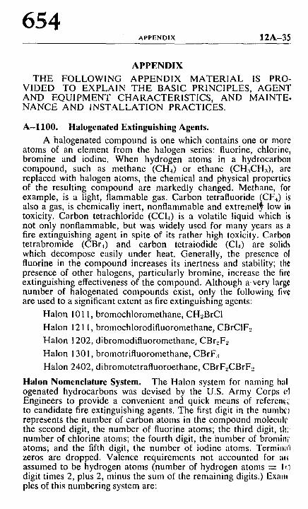
A-1100. Halogenated Extinguishing Agents. A halogenated compound is one which contains one or more
atoms of an element from the halogen series: fluorine, chlorine, bromine and iodine. When hydrogen atoms in a hydrocarbon compound, such as methane (CH4) or ethane (CH:~CH:~), are replaced with halogen atoms, the chemical and physical properties of the resulting compound are markedly changed. Methane, for example, is a light, flammable gas. Carbon tetrafluoride (CF.0 is also a gas, is chemically inert, nonflammable and extremel~ low in toxicity. Carbon tetrachloride (CC14) is a volatile liquid which is not only nonflammable, but was widely used for many years as n fire extinguishing agent in spite of its rather high toxicity. Carbon tetrabromide (CBr4) and carbon tetraiodide (C14) are solids which decompose easily under heat. Generally, the presence ol fluorine in the compound increases its inertness and stability; the presence of other halogens, particularly bromine, increase the fire extinguishing effectiveness of the compound. Although a-very large number of halogenated compounds exist, only the following fivr are used to a significant extent as fire extinguishing agents:
Halon 1011, bromochloromethane, CH...BrCI
Halon 1211, bromochlorodifluoromethane, CBrCIF..
Halon 1202, dibromodifluoromethane, CBr._,F._,
Halon i 301, bromotrifluoromethane, CBrF:~
Halon 2402, dibromotetrafluoroethane, CBrF.,CBrF.,
Halon Nomenclature System. The Halon system for naming h~ll ogenated hydrocarbons was devised by the U.S. Army Corps i,l Engineers to provide a convenient and quick means of referentc to candidate fire extinguishing agents. The first digit in the numbc~ represents the number of carbon atoms in the compound molecult' the second digit, the number of fluorine atoms; the third digit, th', number of chlorine atoms; the fourth digit, the number of bromlni" atoms; and the fifth digit, the number of iodine atoms. Termim~q zeros are dropped. Valence requirements not accounted for al~ assumed to be hydrogen atoms (number of hydrogen atoms -- Ir.~ digit times 2, plus 2, minus the sum of the remaining digits.) Exam pies of this numbering system are:
6 0 0 ': ~ ~'
5 0 0
bJ n-<C
u9 2O0 V~-r
tY 150 (1. - -
n" 0 ~ IOO
(1. <~ 8 0
> 0 6 0
o. Z 0
< ,-g 0
/ /
r
/ ,I 0
- 6 0 - 4 0 - 2 0
/ # "
g,
. I i . r
f
J .
CRITICAL POINT f I Isz.s or, s6o.z ps.o
i / I I I
0 2 0 4 0 6 0 8 0 I 0 0 120 140 160
T E M P E R A T U R E - = F
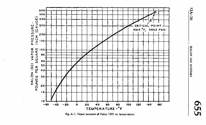
Rg. A-]. Vopor pressure of Halon 1301 vs. temperature.
t J
o'~
O~
U1
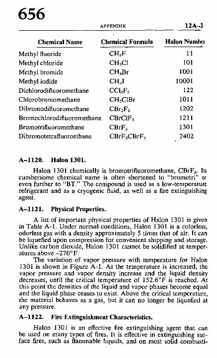
656 APeESDIX 12A-3 :
Chemical Name
Methyl fluoride
Methyl chloride
Methyl bromide
Methyl iodide
Dichlorodifluoromethane
Chlorobromomethane
Dibromodifluoromethane
Bromochlorodifluoromethane
Bromotrifluoromethane
Dibromotetrafluoroethane
Chemical Formula Halon Numlg~
CHaF 11
CH:,C1 101
CH3Br 1001
CHaI 10001
CCI2F~ 122
CH2CIBr 1011
CBr2F2 1202
CBrCIF2 1211
CBrFa 1301
CBrF2CBrFe 2402
A-1120. Halon 1301.
Halon 1301 chemically is bromotrifluoromethane, CBrF3. Its cumbersome chemical name is often shortened to "bromotri" 0r even further to "BT." The compound is used as a low-temperature refrigerant and as a cryogenic fluid, as well as a fire extinguishing agent.
A-1121. Physical Properties.
A list of important physical properties of Halon 1301 is given in Table A-1. Under normal conditions, Halon 1301 is a colorless, odorless gas with a density approximately 5 times that of air. It can be liquefied upon compression for convenient shipping and storage. Unlike carbon dioxide, Halon 1301 cannot be solidified at temper- atures above -270~ �9
The variation of vapor pressure with temperature for Halon 1301 is shown in Figure A-1. As the temperature is increased, the vapor pressure and vapor density increase and the liquid density decreases, until the critical temperature of 152.6~ is reached. At this point the densities of the liquid and vapor phases become equal and the liquid phase ceases to exist. Above the critical temperature, the material behaves as a gas, but it can no longer be liquefied at any pressure.
A-1122. Fire Extinguishment Characteristics.
Halon 1301 is an effective fire extinguishing agent that can be used on many types of fires. It is effective in extinguishing sur- face fires, such as flammable liquids, and on most solid combusti-
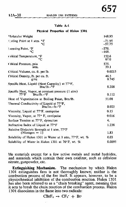
1 ~ A - 3 8 HALON 1301 SYSTEMS
657
Table A-I
Physical Properties of Halon 1301
*-~01ccular Weight IL~illng Point at 1 atm. *F
*C r, ,oozing Point, *F
*C 'dtlcal Temperature, *F
*C t"thical Pressure, psia
atm. (~dtical Volume, cu. ft. per lb. Critical Density, lb. per cu. ft.
g/co Specific Heat, Liquid (Heat Capacity) at 77"F,
Btu/lb.-~ Specific Heat, Vapor, at constant pressure ( 1 arm)
77"F Btu/Ib.-*F Heat of Vaporization at Boiling Point, Btu/lb. Thermal Conductivity of Liquid at 77"F,
Btu/hr.-ft-*F Viscosity, Liquid at 77"F, centipoise Viscosity, Vapor, at 77* F, centipoise Surface Tension at 77"F, dynes/cm Refractive Index of Liquid at 770F Relative Dielectric Strength at 1 atm, 77"F
(Nitrogen = 1) Solubility of Halon 1301 in Water at 1 atm, 77"F, wt. % Solubility of Water in Halon 1301 at 70~ wt. %
148.93 -71.95 -57.75
-270. -168.
152.6 67.0
575. 39.1 0.0215
46.5 0.745
0.208
0.112 51.08
0.025 0.15 0.016 4. 1.238
1.83 0.03 0.0095
ble mater ia ls except for a few active metals and meta l hydrides , and mater ia ls which conta in their own oxidizer , such as cellulose nitrate, gunpowder , etc.
Ext inguishing Mechan i sm. The mechanism by which H a l o n 1301 extinguishes fires is not thoroughly known; nei ther is the combus t ion process of the fire itself. I t appears , however , to be a phys iochemica l inhibi t ion of the combus t ion react ion. H a l o n 1301 has also been referred to as a "chain breaking" agent, meaning that it acts to b r e a k the chain reac t ion of the combus t ion process. H a l o n 1301 dissociates in the flame into two radicals :
CBrFa -~ CF3" + Br"
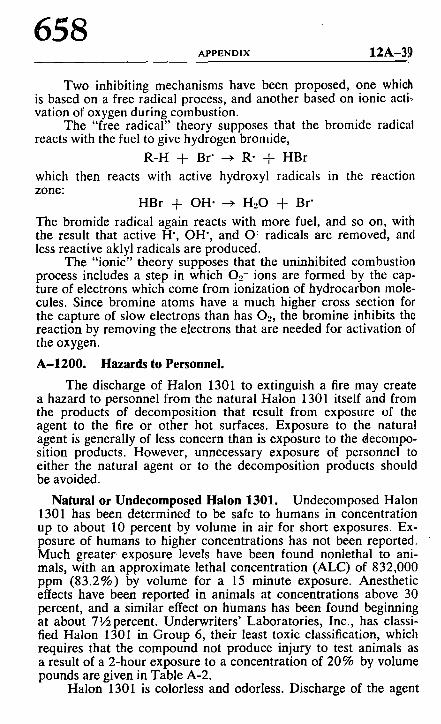
658 A P P E N D I X 12A-39
Two inhibiting mechanisms have been proposed, one which is based on a free radical process, and another based on ionic actio vation of oxygen during combustion.
The "free radical" theory supposes that the bromide radical reacts with the fuel to give hydrogen bromide,
R-H -q- Br" --~ R- -J- HBr
which then reacts with active hydroxyl radicals in the reaction zone:
HBr -t- OH" ~ H20 -I- Br"
The bromide radical again reacts with more fuel, and so on, with the result that active H', OH', and O: radicals are removed, and less reactive aklyl radicals are produced.
The "ionic" theory supposes that the uninhibited combustion process includes a step in which O_~- ions are formed by the cap- ture of electrons which come from ionization of hydrocarbon mole- cules. Since bromine atoms have a much higher cross section for the capture of slow electrons than has O._,, the bromine inhibits the reaction by removing the electrons that are needed for activation of the oxygen.
A - 1 2 0 0 . Hazards to Personnel.
The discharge of Halon 1301 to extinguish a fire may create a hazard to personnel from the natural Halon 1301 itself and from the products of decomposition that result from exposure of the agent to the fire or other hot surfaces. Exposure to the natural agent is generally of less concern than is exposure to the decompo- sition products. However, unnecessary exposure of personnel to either the natural agent or to the decomposition products should be avoided.
Natural or Undecomposed Halon 1301. Undecomposed Halon 1301 has been determined to be safe to humans in concentration up to about 10 percent by volume in air for short exposures. Ex- posure of humans to higher concentrations has not been reported. Much greater exposure levels have been found nonlethal to ani- mals, with an approximate lethal concentration (ALC) of 832,000 ppm (83.2%) by volume for a 15 minute exposure. Anesthetic effects have been reported in animals at concentrations above 30 percent, and a similar effect on humans has been found beginning at about 7�89 Underwriters' Laboratories, Inc., has classi- fied Halon 1301 in Group 6, their least toxic classification, which requires that the compound not produce injury to test animals as a result of a 2-hour exposure to a concentration of 20% by volume pounds are given in Table A-2.
Halon 1301 is colorless and odorless. Discharge of the agent
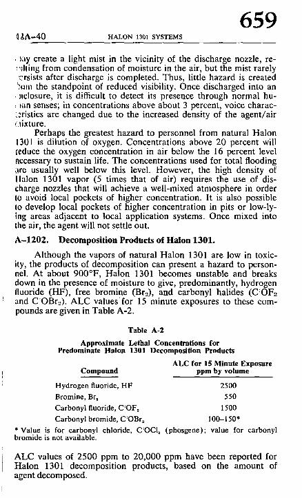
~ A - 4 0 HALON 1301 SYSTEMS
659
t;~y create a light mist in the vicinity of the discharge nozzle, re- :,~lling from condensation of moisture in the air, but the mist rarely ~rsists after discharge is completed. Thus, little hazard is created ~om the standpoint of reduced visibility. Once discharged into an aclosure, it is di~cult to detect its presence through normal hu- ron senses; in concentrations above about 3 percent, voice charac-
~:rlstics are changed due to the increased density of the agent/air f~ixture.
Perhaps the greatest hazard to personnel from natural Halon a301 is dilution of oxygen. Concentrations above 20 percent will seduce the oxygen concentration in air below the 16 percent level accessary to sustain life. The concentrations used for total flooding l)re usually well below this level. However, the high density of Ilalon 1301 vapor (5 times that of air) requires the use of dis- dlarge nozzles that will achieve a well-mixed atmosphere in order to avoid local pockets of higher concentration. It is also possible to develop local pockets of higher concentration in pits or low-ly- ing areas adjacent to local application systems. Once mixed into the air, the agent will not settle out.
A - 1 2 0 2 . Decompos i t ion Products of Ha lon 1301 .
Although the vapors of natural Halon 1301 are low in toxic- ity, the products of decomposition can present a hazard to person- nel. At about 900~ Halon 1301 becomes unstable and breaks down in the presence of moisture to give, predominantly, hydrogen fluoride (I-IF), free bromine (Br2), and carbonyl halides (C:OF.o and C:OBr._,). ALC valuesfor 15 minute exposures to these com- pounds are given in Table A-2.
Table A-2
Approximate Lethal Concentrations for Predominate Halon 1301 Decomposition Products
ALC for 15 Minute Exposure Compound ppm by volume
Hydrogen fluoride, HF 2500 Bromine, Br~ 550 Carbonyl fluoride, C:OF~ 1500 Carbonyl bromide, C:OBr~ 100-150*
* Value is for carbonyl chloride, C:OCI~ (phosgene); value for carbonyl bromide is not available.
ALC values of 2500 ppm to 20,000 ppm have been reported for Halon 1301 decomposition products, based on the amount of agent decomposed.
660 APPEnDiX 12A-41
The decomposition products of Halon 1301 have a charac* teristic sharp, acrid odor, even in minute concentrations of only a few parts per million. This characteristic provides a built-in warn- ing system for the agent, but at the same time creates a noxious, irritating atmosphere for those who must enter the hazard follow- ing the fire.
The amount of Halon 1301 which can be expected to decom- pose in extinguishing a fire depends to a large extent upon the size of the fire, the size of the enclosure, and the rapidity with which the agent is discharged. For example, extinguishment of a 25 square foot heptane fire in a 10,000 cubic foot enclosure within 0.5 seconds produced only 12 ppm HF. A similar test having an extinguishment time of 10 seconds produced an average HF level of 250 ppm over a 9 minute period. Equivalent tests taking up to one minute for extinguishment would probably produce an atmosphere which would be quite hazardous to personnel. From this standpoint, it is advantageous to employ the most rapid detection system possible and to discharge the agent in the minimum possible time.
A-1211. Safety Requirements. The steps and safeguards necessary to prevent injury or death
to personnel in areas whose atmospheres will be made hazardous by the discharge or thermal decomposition of Halon 1301 may include the following:
1. Provision of adequate aisleways and routes of exit and keeping them clear at all times.
2. Provision of the necessary additional and/or emergency lighting and directional signs to ensure quick, safe evacuation.
3. Provision of alarms with such areas that will operate im- mediately upon detection of the fire. For design concentrations of Halon 1301 above 20 percent by volume, the discharge of Halon 1301 and the activation of automatic door closures should be de- layed for sufficient time to evacuate personnel from the area.
4. Provision of only outward swinging self-closing doors at exits from hazardous areas, and, where such doors are latched, provision of panic hardware.
5. Provision of continuous alarms at entrances to such areas until the atmosphere has been restored to normal.
6. Provision of warning and instruction signs at entrances to and inside such areas.
7. Provision for prompt discovery and rescue of persons ren- dered unconscious in such areas. This may be accomplished by hav- ing such areas searched immediately by trained men equipped with proper breathing equipment. Self-contained breathing equipment and personnel trained in its u~e, and in rescue practices, including artificial respiration, should be readily available.
1 2 A - 4 2 HALON 1301 SYSTEMS
661
8. Provision of instruction and drills of all personnel within ~r in the vicinity of such areas, including maintenance or construc-
t!on people who may be brought into the area, to insure their cor- .'ect action when Halon 1 301 protective equipment operates.
9. Provision of means for prompt ventilation of such areas. t~'orced ventilation will often be necessary. Care should be taken to ~ally dissipate hazardous atmospheres and not merely move them t0 another location. Halon 1301 is heavier than air.
10. Provision of such other steps and safeguards that a care- fl, I study of each particular situation indicates are necessary to prevent injury or death.
A-1220. Electrical Clearance.
The clearances in Table A-3 were obtained f rom the National Electrical Code and publications of the National Electrical Manu- |acturers Association (NEMA).
Table A-3
Minimum Clearance of System Components from
Live Electrical Apparatus
Distance Line Voltage (in.) Line Voltage
Distance (in.)
600 orless 1" 92,000 30 2,500 2* 115,000 37 5,000 3* 138,000 44
15,000 6 161,000 52 25,000 8 196,000 63 34,500 12 230,000 76 46,000 15 287,000 98 69,000 23 345,000 120
* For interior dry locations. NO'rE: With the exception of those marked with an asterisk, the clearances
given are for transformers operating at altitudes of 3,300 feet or less. For operation at altitudes in excess of 3,300 feet, the clearance shall be increased at the rate of 1 percent per 330 feet increase in altitude in excess of 3,300 feet.
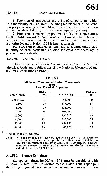
A - 1 5 5 0 . Storage Containers.
Storage containers for Ha lon 1301 must be capable of with- standing the total pressure exerted by the Halon 1301 vapor plus the nitrogen partial pressure, at the maximum temperature con-
662 APPENDIX 12A--43
templated in use. Generally, steel cylinders meeting the U.S. De partment of Transportation requirements will be used to contail~ quantities up to abont 100 pounds Halon 1301, or manifolded cylinders for larger installations.
Specially designed containers, such as spheres, are also used, particularly in high rate discharge systems. For very large systems, bulk storage tanks may be used, provided the design requirement,~ of the ASME Unfired Pressure Vessel Code are followed.
Each container must be equipped with a discharge valve ca- pable of discharging liquid Halon 1301 at the required rate. Con- tainers with top-mounted valves require an internal dip tube ex- tending to the bottom of the cylinder to permit discharge of liquid phase Halon 1301.
? . 2 0 -
210 -
2 0 0
190
180
170
tdo
TEMPERATUREj " F
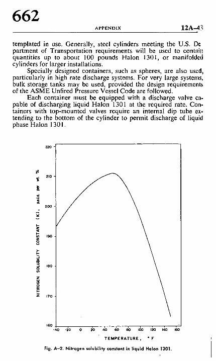
Fig. A-2. Nitrogen solubility constant in liquid Halon 1301.
,~o
~]A-4~ HALON 1301 SYSTEMS
663
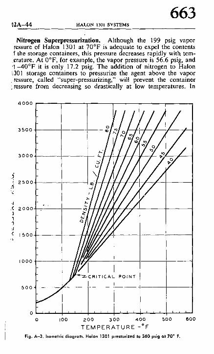
Nitrogen Superpressurization. Although the 199 psig vapor rcssure of Halon 1301 at 70~ is adequate to expel the contents f the storage containers, this pressure decreases rapidly with tem-
.r At 0~ for example, the vapor pressure is 56.6 psig, and ' I - 4 0 ~ it is only 17.2 psig. The addition of nitrogen to Haion l~301 storage containers to pressurize the agent above the vapor L tessure, called "super-pressurizing," will prevent the container i, ressure from decreasing so drastically at low temperatures. In
4 0 0 0
3500
3000
~, 2500 h
4 ,( 2000
I I g
1500
I 0 0 0
500
F L r -
F
0 L I i l ~ I
0 I 00
://, J///, d f :'-
~'-~ C RI TIC A L POINT
1 i 1 1 L I 1 I t 1 i i
200 300 400 500 600
TEMPERATURE -~ Fig. A-3. Isometric diagram. Halon 1301 pressurized to 360 psig at 70 ~ F.
664 APPENDIX 12A-45
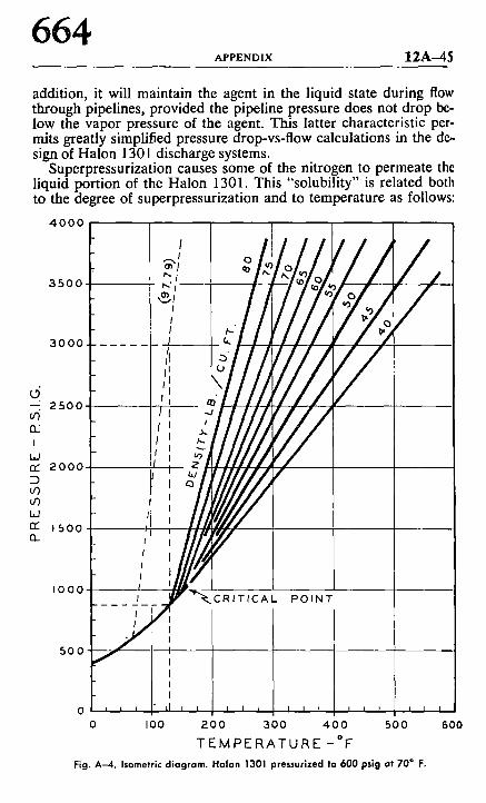
addition, it will maintain the agent in the liquid state during flow through pipelines, provided the pipeline pressure does not drop be- low the vapor pressure of the agent. This latter characteristic per- mits greatly simplified pressure drop-vs-flow calculations in the de- sign of Halon 1301 discharge systems.
Superpressurization causes some of the nitrogen to permeate the liquid portion of the Halon 1301. This "solubility" is related both to the degree of superpressurization and to temperature as follows:
4000
3500
3000
d --. 2 5 0 0 u')
n '
I L,J rr" 2 0 0 0
o3 u3 W r r 1 5 0 0 r,
I 0 0 0
5 0 0
0 0 I 0 0 2 0 0 3 0 0 4 0 0 5 0 0
T E M P E R A T U R E - O F
Fig. A - 4 . Isometric diagram. Halon 1301 pressurized to 600 pslg at 70 ~ F.
600
12A-46 HALON 1301 SYSTEMS
665
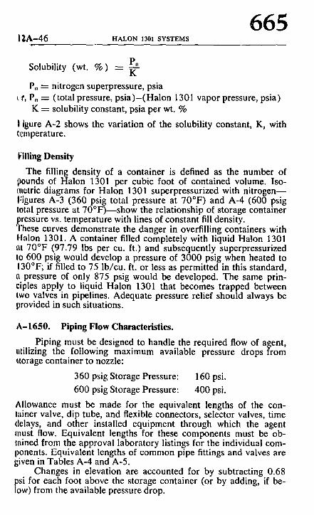
Pn Solubility (wt. % ) -- ~--
I),, -- nitrogen superpressure, psia t.r, P, -- (total pressure, psia)-(Halon 1301 vapor pressure, psia)
K ---- solubility constant, psia per wt. %
i igure A-2 shows the variation of the solubility constant, K, with ~mperature.
f l l l ing Density
The filling density of a container is defined as the number of ~ounds of Halon 1301 per cubic foot of contained volume. Iso- ctletric diagrams for Halon 1301 superpressurized with nitrogen-- I:igures A-3 (360 psig total pressure at 70~ and A-4 (600 psig total pressure at 70~ the relationship of storage container rcssure vs. temperature with lines of constant fill density. hese curves demonstrate the danger in overfilling containers with
Halon 1301. A container filled completely with liquid Halon 1301 at 70~ (97.79 lbs per cu. ft.) and subsequently superpressurized to 600 psig would develop a pressure of 3000 psig when heated to 130~ if filled to 75 lb/cu, ft. or less as permitted in this standard, a pressure of only 875 psig would be developed. The same prin- ciples apply to liquid Halon 1301 that becomes trapped between two valves in pipelines. Adequate pressure relief should always be provided in such situations.
A-1650. Piping Flow Characteristics.
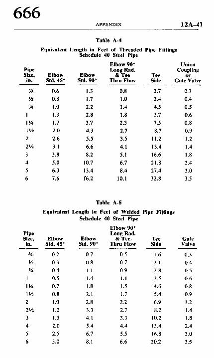
Piping must be designed to handle the required flow of agent, utilizing the following maximum available pressure drops from ~torage container to nozzle:
360 psig Storage Pressure: 160 psi.
600 psig Storage Pressure: 400 psi.
Allowance must be made for the equivalent lengths of the con- tainer valve, dip tube, and flexible connectors, selector valves, time delays, and other installed equipment through which the agent must flow. Equivalent lengths for these components must be ob- tained from the approval laboratory listings for the individual com- ponents. Equivalent lengths of common pipe fittings and valves are given in Tables A-4 and A-5.
Changes in elevation are accounted for by subtracting 0.68 psi for each foot above the storage container (or by adding, if be- low) from the available pressure drop.
666 APPENDIX 12A---47
Table A-4
Equivalent Length in Feet of Threaded Pipe Fittings Schedule 40 Steel Pipe
Elbow 90 ~ Union Pipe Long Rad. Coupling Size, Elbow Elbow & Tee Tee or
in. Std. 45 ~ Std. 90 ~ Thru Flow Side Gate Valve
a/a 0.6 1.3 0.8 2.7 0.3
�89 0.8 i.7 1.0 3.4 0.4
a,~ 1.0 2.2 1.4 4.5 0.5
1 1.3 2.8 1.8 5.7 0.6
1�88 1.7 3.7 2.3 7.5 0.8
11,,5 2.0 4.3 2.7 8.7 0.9
2 2.6 5.5 3.5 11.2 1.2
2 �89 3.1 6.6 4.1 13.4 1.4
3 3.8 8.2 5.1 16.6 1.8
4 5.0 10.7 6.7 21.8 2.4
5 6.3 13.4 8.4 27.4 3.0
6 7.6 1'6.2 10.1 32.8 3.5
Table A-5
Equivalent Length in Feet of Welded Pipe Fittings Schedule 40 Steel Pipe
Elbow 90 ~ Pipe Long Rad. Size, Elbow Elbow & Tee. Tee Gate
in. Std. 45 ~ Std. 90 ~ Thru Flow Side Valve
3/s 0.2 0.7 0.5 1.6 0.3
�89 0.3 0.8 0.7 2.1 0.4
3,4 0.4 1.1 0.9 2.8 0.5
1 0.5 1.4 I.I 3.5 0.6
1�88 0.7 1.8 1.5 4.6 0.8
1 �89 0.8 2.1 1.7 5.4 0.9
2 1.0 2.8 2.2 6.9 1.2
21/5 1.2 3.3 2.7 8.2 1.4
3 1.5 4.1 3.3 10.2 1.8
4 2.0 5.4 4.4 13.4 2.4
5 2.5 6.7 5.5 16.8 3.0
6 3.0 8. I 6.6 20.2 3.5
112A-48 HALON 1301 SYSTEMS
667
~1720. Maintenance.
The entire fire extinguishing system should be completely in- ;~ccted at least annually. More frequent general inspections are , ~commended.
In the annual inspection particular attention should be given
I. Detection and Actuation System. 2. Agent Supply. 3. Piping and Nozzles. 4. Auxiliary Equipment.
I. Detection and Actuation System. A. The detectors should be checked (and cleaned if neces-
sary) to assure that they are free of foreign substances.
B. If the detection system is supervised, the supe/'visory fea- tures should be checked to determine that the detection system is in satisfactory condition. The methods and pro- cedures for this inspection should be in accordance with the manufacturer's recommendations.
C. Automatic actuating controls should be removed from the containers equipped with such controls ("pilot cylinders") and a test made of the detection system by introducing a simulated fire condition at one or more detectors (heat, smoke, etc., as applicable). The actuating controls muzt move to the "discharged" position.
D. All manual operating devices (pull boxes, manual electric switches, etc.) should be operated with the actuating con- trol removed from the supply containers equipped with such controls ("pilot cylinders"). The actuating control must move to the "discharged" position.
E. All actuating controls must be reset and reinstalled after testing.
2. Agent Supply. A. All containers shall be weighed to determine the contents
of the container. Any container showing a loss of more than 5 percent of the marked net contents shall be refilled or replaced.
B. Containers shall be examined for evidence of corrosion or mechanical damage.
C. When required (see paragraph 1552) the pressure within the container shall be checked against the marked pres- sure. If the pressure (corrected for temperature) within
668 APPENDIX 12A-..4',J
the container varies more than 10 percent from tk: marked pressure the container shall be refilled or replaced
D. Container bracketing, supports, etc., should be checke(! to determine that their condition is satisfactory.
3. Piping and Nozzles. A. Piping should be examined for any evidence of corrosion B. P i p e hangers and/or straps should be examined to see tht
the piping is securely supported. C. Nozzles should be checked to determine that the orifir162
are clear and unobstructed. D. Where nozzle seals are provided, they should be checked
for signs of deterioration, and replaced if necessary. E. Nozzles should be checked for proper position and align:
ment.
4. Auxiliary Equipment. A. All auxiliary and supplementary components such a~
svr door and window releases, interconnected valves, damper releases, supplementary alarms, etc., should be manually operated (where possible) to ensure that the) are in proper operating condition.
B. All devices should be returned to normal "standby" con~ dition after testing.
A-2100. General Information on Total Flooding Systems. From a performance viewpoint, a total flooding system is de.
signed to develop a concentration of Halon 1301 that will extin~ guish fires in combustible materials located in an enclosed space. It must also maintain an effective concentration until the maximunl temperature has been reduced below the reignition point.
The concentration of Halon 1301 required will depend on the type of combustible material involved. This has been determined for many surface-type fires, particularly those involving liquids and gases. For deep-seated fires, the critical concentration required fol extinguishment is less definite, and has in general been established by practical test work.
The volume of Halon 1301 required to develop a given con- centration will be greater than the final volume remaining in the enclosure. In most cases, Halon 1301 must be applied in a manner that promotes progressive mixing of the atmosphere. The displaced atmosphere is exhausted freely from the enclosure through small openings or through special vents, as Halon 1301 is injected. Some Halon 1301 is therefore lost with the vented atmosphere. This loss is greater at high concentrations.
t ~A-50 HALON 130t SYSTEMS 669
For the purposes of this standard, it is assumed that the '~lon 1301/air mixture lost in this manner contains the final de- ,~0 concentration of Halon 1301. This represents the worst case im a theoretical standpoint, and provides a built-in safety factor ~compensate for non-ideal discharge arrangements.
The volume of Halon 1301 required to develop a given con- c3tration in the enclosure is given by the following equation:
C X - -
100 - C
where x - - cu. ft. of Halon 1301 injected per cu. ft. enclosed volume
C ---- concentration of Halon 1301, percent by vol.
The specific volume of Halon 1301 vapor at 70~ and 1.0 atm 2.56 cu. ft. per pound. From the preceding equation, the mass
r~lr volume flooding factors may be calculated:
x C F m - - - - 0.391 ( _ (~)
v 100
F , _ v _ 2.56 ( 1 0 0 - C )
where v z specific volume of Halon 1301 vapor, cu. ft. per pound
F m - - mass flooding factor, pounds Halon 1301 injected per cu. ft. enclosed volume
F~ ---- volume flooding factor, cu. ft. enclosed volume per pound Halon 1301
The curve of flooding factor vs. concentration given in Chal> c:r 2, Fig. 3, is based on expansion of Halon 1301 at 70~ For ~,ther design temperatures, the proper flooding factor may be cal- tulated from the above equations, using the proper value of specific volume.
A - 2 2 2 1 . Effects of Venti lat ion.
NOTE: See A-2431 for treatment of Halon 1301 leakage through enclosure openings.
Halon 1301 discharged into a ventilated enclosure for total Ilooding is subject to loss of agent in the effluent ventilating air. A greater amount of agent may be required to develop a given con- cent.ration, and continuous agent discharge is required to maintain the concentration at a given constant.level.
Beginning with an enclosure containing pure air, the Halon 1301 discharge rate required to develop a given concentration of
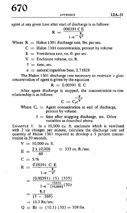
670 APPENDIX 1 2 A - 5 1
agent at any given time after start of discharge is as follows: 000391 C E
R - - E
1 - r - - V r
Where R - - Halon 1301 discharge rate, lbs. per sec.
C ---- Ha lon 1301 concentration, percent by volume
E = Ventilation rate, cu. ft. per sec.
V - - Enclosure volume, cu. ft.
T = time, sec.
e = natural logari thm base, 2 .71828
The Halon 1301 discharge rate necessary to maintain a givefl concentrat ion of agent is given by the equation
R - - 0.00391 E C
After agent discharge is stopped, the concentration-vs-time relationship is as follows:
E - - T
C ---- Coe v
Where Co = Agent concentrat ion at end of discharge, percent by volume.
T - - time after stopping discharge, sec. Other variables as described above.
EXAMPLE 1: In a 10,000 cu. ft. enclosure which is ventilated with 2 air changes per minute, calculate the discharge rate and quantity of Halon 1301 required to develop a 5 percent concen. tration in 30 seconds.
V = 10,000 cu. ft.
2 x 10,000 = 333 cia. ft ./sec. E - -
60
C = 5 . %
0".00391 C E R - -
E 1-e - V r
(0 .00391) (5) (333) _ _ ( 3 3 3 ) ( ~ f ) ~
1-e ( 1 0 , 0 0 0 ) ,, o ~ , ,
~5.5 - - ( 1 - .369)
- - 10.3 lbs/sec.
Q = Rt = ( 1 0 . 3 ) ( 3 0 ) = 3 0 9 1 b s .
0 2 A - 5 2 HALON 1301 SYSTEMS
671
"~AMPLE 2: After achieving a 5 percent concentration of Halon ]01 in the above example, calculate the continuous discharge rate
..~cessary to maintain the agent concentration at 5 percent:
R = .00391 (333) (5)
= 6.5 lb/sec
~-2300. Halon 1301 Requirements for Surface Fires.
Two basic types of extinguishment data have been obtained ;~r Halon 1301:
(1) flame extinguishment data , which determine the agent , oncentration necessary to extinguish a flame of a particular fuel.
(2) inerting data, which determine the minimum agent con- ,r to suppress propagation of a flame front at the "flam- qability peak," or stoichiometric fuel/air composition.
Flame extinguishment data generally relate closest to the con- ~entration actually required in a fire extinguishing system. The ~easurements are often made with pan fires on a large scale, so ~hat realistic conditions exist. The concentration requirements for !arge scale fires have been found to be the same as determined from small-scale pan fires in laboratory apparatus, provided the test conditions do not permit a significant amount of oxygen de- pletion before or during the extinguishment test. Agent concentra- fl0ns obtained by this type of test are characteristically 20 to 50 ~ercent lower than concentrations required for complete inerting.
In inerting measurements, a fuel/air/agent mixture is con- lained in a test chamber, such as an explosion burette, and an ignition source is activated. If the mixture cannot support a flame front, the mixture is considered to be nonflammable. The results may be plotted as shown in Figure A-5.
The normal flammability range which exists when no agent I~ present is shown at the left-hand side of the graph. As Halon 1301 is added to the system, the flammability range is reduced until it finally disappears entirely. The agent concentration at which this occurs is called the "flammability peak" concentration. All fuel-air mixtures containing concentrations of agent equal to or greater than the flammability peak value are nonflammable, hence the term "inert."
The choice between using the flame extinguishing concentration or the inerting concentration for a given fuel depends upon (1) the volatility characteristics of the fuel, (2) the quantity of fuel pres- ent, and (3) the conditions of use in the hazard. Applying Halon 1301 at the flame extinguishment concentration to actual fires will effectively extinguish the fire at no sacrifice in the reliability of the
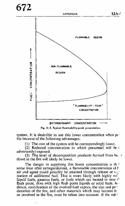
672 A P P E N D I X 12A-~
Z O
I - ,11
I - z bJ U z O r
,_1 laJ
M.
E REGION
NON- FL.t~IMABLE
. \ i �9
" FLAMMABILITY - PEAK "
CONCENTRATION
E X T I N G U I S H A N T CONCENTRATION
Fig. A - 5 . Typica l f l ammab i l l t y -peak presentation.
system. It is desirable to use this lower concentration when IW ble because of the following advantages:
(1) The cost of the system will be correspondingly lower. (2) Reduced concentration to which personnel will be /
advertently) exposed. (3) The level of decomposition products formed from I}lx
down in the fire will likely be lower.
The danger in supplying this lower concentration is Ill '1 some time after extinguishment, a flammable concentration ,11 air and agent could possibly be attained through release or ~,,, ization of additional fuel. This is more likely with highly v,.~ liquid fuels, gaseous fuels, or fuels which are heated to near ~': flash point, than with high flash point liquids or solid fuels, h~ ~ dition, stratification of the evolved fuel vapors, the size and pw" duration of the fire, and other materials which may become h', or involved in the fire, must be taken into account. If the vol::~
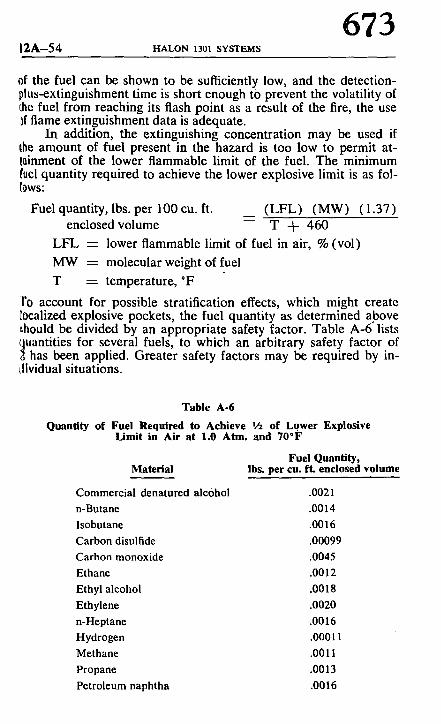
12A-54 l-~d..ON 1301 SYSTF_._MS
673
of the fuel can be shown to be sufficiently low, and the detection- olus-extinguishment time is short enough tO prevent the volatility of 0ae fuel from reaching its flash point as a result of the fire, the use ff flame extinguishment data is adequate.
In addition, the extinguishing concentration may be used if Ihe amount of fuel present in the hazard is too low to permit at- lainment of the lower flammable limit of the fuel. The minimum Iuel quantity required to achieve the lower explosive limit is as fol- lows:
Fuel quantity, lbs. per 100 cu. ft. (LFL) (MW) (1.37) enclosed volume - - T ~ 460
L FL - - lower flammable limit of fuel in air, % (vol)
MW ~ molecular weight of fuel
T ---- temperature, *F
1'o account for possible stratification effects, which might create C0calized explosive pockets, the fuel quantity as determined above ~hould be divided by an appropriate safety factor. Table A-6" lists
~ uantities for several fuels, to which an arbitrary safety factor of has been applied. Greater safety factors may be required by in-
~lividual situations.
Table A-6
Quantity of Fuel Required to Achieve I/2 of Lower Explosive Limit in Air at 1.0 Attn. and 70*F
Fuel Quantity, Material Ibs. per cu. ft. enclosed volume
Commercial denatured alcohol .0021 n-Butane .0014 Isobutane .0016 Carbon disulfide .00099 Carbon monoxide .0045 Ethane .0012 Ethyl alcohol .0018 Ethylene .0020 n-Heptane .0016 Hydrogen .00011 Methane .0011 Propane .0013 Petroleum naphtha .0016
674 APPENDIX 12 A---~ ~',
A-2400. Deep Seated Fires. No firm basis, either theoretical or empirical has as yet bec:~
determined to enable generalized prediction of the requirement fi,*) extinguishment of deep seated fires.
The soaking time required for extinguishment will be depend ent on the concentration used and this relationship will in turn bt dependent on the heat balance of the fuel array.
To form a basis for estimating requirements presupposes soml knowledge of what the fire will be, for example, how deep seatr is it. This can vary widely between fuel ignited on the surface anr fuel which becomes ignited due to internal self-heating. The lengl~ of time that the material burns before suppression is initiated wliJ also bear on the requirements for suppression. The fact that I*~ many cases the fuel cannot be described as a fixed, nonchangi,~, array further complicates the problem.
The questions in system design become: What is the desire~,l end result? What is the required level of confidence and probabilic) that the desired effect will be accomplished?
A-2422. Fuel Arrangement. The rate at which heat may be dissipated from a deep-seated rite
after the oxidation reaction of the fire has been stopped will depenti largely upon the heat transfer characteristics from the fuel bed to the surroundings. Since radiation is an important heat transfeg mechanism at temperatures encountered in a fire, the arrangement of the fuel is an important variable. Figure 4 in Chapter 2 is based on fuel arrays which are discontinuous, i.e., do not contain exten~ sive plane surfaces in close proximity. For continuous arrays, the Halon 1301 concentration/soaking time requirements may be con. siderably greater than indicated.
A-2431. Leakage of Halon 1301 Through Enclosure Openings. NOTE: See A-2220 for effects of forced ventilation. Halon 1301 discharged into an enclosure for total flooding,
will result in an air/agent mixture which has a higher specific grav- ity than the air surrounding the enclosure. Therefore, any opening in the walls of the enclosure will allow the heavier air/agent mix- ture to'flow out of the enclosure, being replaced with lighter outside air flowing into the enclosure through the same opening. The rate at w.hich agent is lost through openings will depend upon the height and width of the opening, the location of the opening in the wall, and the concentration of agent in the enclosure.
Fresh air entering the enclosure will collect toward the top, forming an interface between the air/agent mixture and fresh air. As leakage proceeds, the interface will move toward the bottom 0[ the opening. The space below the interface will contain essentially
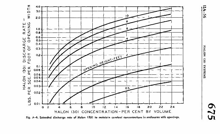
T" 4 . 0 I-- (3 3.0
2 .0 I
u d O
F - - Z < - - hO n" Z 0.8
b.l n 0.6 0 0 0 .5 n- 0.4
< ~ 0.3 I ',9 I-- 0,2
0
s 2 ~. 0,I
cq b.l 0.08
- - n 0.06 z d o, o5 0 hi 0 .04 .._1 u') < 0.03 7- n"
UJ 8.. 0.02
~4 j o.o I
o
/ . / / /
J / / I - / / �9
/ / / . i - / / /
" / / o5
O l I ~ l I I I I
2 4 6 8 I0 12 14 16 18 2 0 22
H A L O N 1301 C O N C E N T R A T I O N - P E R C E N T B Y V O L U M E
2 4
Fig. A-6. Extended discharge rate of Halon 1301 to maintain constant concentrations in enclosures with openings.
O~ - 4
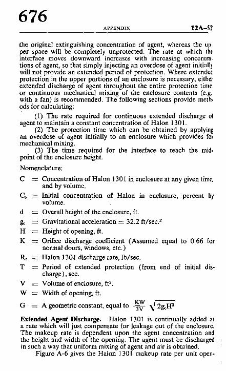
676 APPENDIX 12A-5'~
the original extinguishing concentration of agent, whereas the up per space will be completely unprotected. The rate at which the interface moves downward increases with increasing concentrn~ tions of agent, so that simply injecting an overdose of agent initiall) will not provide an extended period of protection. Where extended protection in the upper portions of an enclosure is necessary, eitheJ extended discharge of agent throughout the entire protection time or continuous mechanical mixing of the enclosure contents (e.g. with a fan) is recommended. The following sections provide meth, ods for calculating:
(1) The rate required for continuous extended discharge 0f agent to maintain a constant concentration of Halon 1301.
(2) The protection time which can be obtained by applyin8 an overdose of agent initially to an enclosure which provides fol mechanical mixing.
(3) The time required for the interface to reach the mid. point of the enclosure height.
Nomenclature:
C --- Concentration of Halon 1301 in enclosure at any given time, and by volume.
Co - - Initial concentration of Halon in enclosure, percent by volume.
d = Overall height of the enclosure, ft.
g~ - - Gravitational acceleration --- 32.2 ft/sec. 2
H = Height of opening, ft.
K - - Orifice discharge coefficient (Assumed equal to 0.66 for normal doors, windows, etc.)
Rf - - Halon 1301 discharge rate, lb/sec.
T - - Period of extended protection (from end of initial dis- charge), see.
V - - Volume of enclosure, ft a.
W - - Width of opening, ft. KW
G - - A geometric constant, equal to -Tv- ~/2g~Ha
Extended Agent Discharge. Halon 1301 is continually added at a rate which will just compensate for leakage out of the enclosure. The makeup rate is dependent upon the agent concentration and the height and width of the opening. The agent must be discharged in such a way that uniform mixing of agent and air is obtained.
Figure A-6 gives the Halon 1301 makeup rate per unit open-
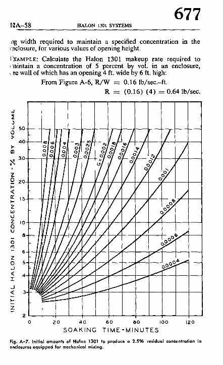
0lA-58 FIALON 1301 SYSTEMS
677
ng width required to maintain a specified concentration in the r:aclosure, for various values of opening height.
(~X^MPLE: Calculate the Halon 1301 makeup rate required to c~aintain a concentration of 5 percent by vol. in an enclosure, < ne wall of which has an opening 4 ft. wide by 6 ft. high:
From Figure A-6, R / W -- 0.16 lb/sec.-ft.
R - - (0.16) (4) - - 0 . 6 4 lb/sec.
,d Ii )
4 0 - ao ~ v - -_o~
O . o o l o', 30
, / Z o 20 1
5,~ II / ,11 ,o I111 I i / / 7 ; ' 1 8
IJll/l Y/"li, , - 6
~ r k / / H A ~ l l " 0 5 J
d ~
Z ,
i
I / ' / /io.o ~ i 1Z__ i ~ / i /
/ I I t I , ' L - -
i ' S / I ' t <>,,~__
i i
0 2 0 4 0 6 0 8 0 I00 12.0
SOAKING T I M E - M I N U T E S
Fig. A'-7. Initial amounts of Halon 1301 to produce a 2.5% residual concentration in enclosures equipped for mechanical mixing.
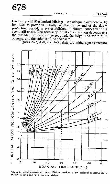
678 A P P E N D I X 1 2 A - b
Enclosure with Mechanical Mixing: An adequate overdose of HI: Ion 1301 is provided initially, so that at the end of the desirr protection period, a prc-cstablishcd minimum concentration ~, agent still exists. The necessary initial concentration depends up0: the extended protection time required, the height and width of th opening, and the volume of the enclosure.
Figures A-7, A-8, and A-9 relate the initial agent concentrt
ILl
5 0
l,!/ / 2O " O~
' /,//W////r �9 : t ,7 - " 7
< I
- - I I -
Z I - - I
2 I
0 2 0 4 0 60 BO I00 120
SOAKING TIME-MINUTES
Fig. A-8. Initial amounts of Halon 1301 to produce a 5% residual concentration h enclosures equipped for mechanical mixing.
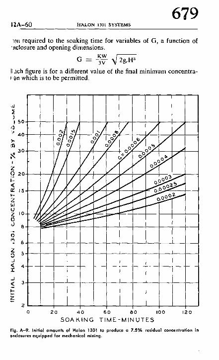
tt2.A-60 H A L O N 1301 SYSTEMS
679
'~m required to the soaking time for variables of G, a function of �9 llclosure and opening dimensions.
G KW ~/ - - 3v 2g"H3
ach figure is for a different value of the final minimum concentra- t' 0n which is to be permitted.
)
///; z
~J
I -
2 0 20 4 0 60 80 I 0 0 120
S O A K I N G T I M E - M I N U T E S
Fig. A-9. Initial amounts of Halon 1301 to produce a 7..5% residual concentration in 0nclosures equipped for mechanical mixing.
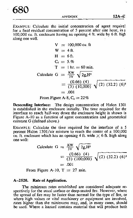
680 APPENDIX 12A-61
EXAMPLE: Calculate the initial concentration of agent requiro.q for a final residual concentration of 5 percent after one hour, in 0 100,000 cu. ft. enclosure having an opening 4 ft. wide by 6 ft. high along one wall.
V = 100,000cu. ft
W --- 4f t .
H = 6 f t .
C~ --- 5.%
T - - l hr. --- 60 min.
Calculate G KW - - 3V 2g~H3
_ (0.66) (4) [ ( 2 ) (32.2) (6) ~
- - ( 3 ) ( 1 0 , 0 0 o )
- - .001
From Figure A-8, Co - - 22%
Descending Interface: The design concentration of Halon 1301 is established in the enclosure initially. The time required for the interface to reach half-way down the enclosure height is shown in Figure A-10 as a function of agent concentration and geometrical constant G (defined above.)
EXAMPLE: Calculate the time required for the interface of a 5 percent Halon 1301/air mixture to reach the center of a 100,000 cu. ft. enclosure which has an opening 4 ft. wide 7( 6 ft. high along one wall:
KW Calculate G --- ~ ~ /2g~H 3
_ (0.66) (4) X/ - - (3) (100,000) __ (2 ) (32.2) (6) a
--- .001
From Figure A-10, T - - 27 rain.
A-2520. Rate of Application.
The minimum rates established are considered adequate re- spectively for the usual surface or deep-seated fire. However, where the spread of fire may be faster than normal for the type of fire, or where high values or vital machinery or equipment are involved, rates higher than the minimums may, and, in many cases, should be used. Where a hazard contains material that will produce both
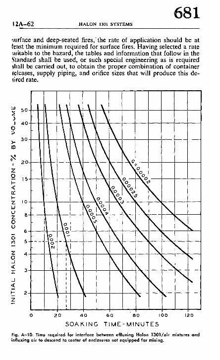
12A-62 HALON 1301 SYSTEMS 681
~urface and deep-seated fires,the rate of application should be at ~cast the minimum required for surface fires. Having selected a rate ~uitable to the hazard, the tables and information that follow in the .~tandard shall be used, or such special engineering as is required ~hall be carried out, to obtain the proper combination of container It:leases, supply piping, and orifice sizes that will produce this de- llred rate.
A 4O
l/X\' ~ ~ \
o_ is . . . . . l
Z I0- - - , ~
oo o \ .
x'\ _j I t N N < l
t
I
2 0 4 0 6 0 8 0 I 0 0 120
S O A K I N G T I M E - M I N U T E S
Fig. A-10. Time required for interface between efffuxlng Halon 1301/air mixtures and inAuxing air to descend to center of enclo~sures not equipped for mixing.