Embed Size (px)
Citation preview
HAL Id: hal-01764553https://hal.archives-ouvertes.fr/hal-01764553
Submitted on 12 Apr 2018
HAL is a multi-disciplinary open accessarchive for the deposit and dissemination of sci-entific research documents, whether they are pub-lished or not. The documents may come fromteaching and research institutions in France orabroad, or from public or private research centers.
L’archive ouverte pluridisciplinaire HAL, estdestinée au dépôt et à la diffusion de documentsscientifiques de niveau recherche, publiés ou non,émanant des établissements d’enseignement et derecherche français ou étrangers, des laboratoirespublics ou privés.
H&HIL: A novel tool to test control strategy withHuman and Hardware In the Loop
Bruno Jeanneret, Daniel Ndiaye, Sylvain Gillet, Rochdi Trigui
To cite this version:Bruno Jeanneret, Daniel Ndiaye, Sylvain Gillet, Rochdi Trigui. H&HIL: A novel tool to test con-trol strategy with Human and Hardware In the Loop. VPPC 2017 (Vehicle Power and PropulsionConference), Dec 2017, BELFORT, France. �hal-01764553�
H&HIL: A novel tool to test control strategy withHuman and Hardware In the Loop
Bruno Jeanneret, Daniel Ndiaye, Sylvain Gillet and Rochdi TriguiIFSTTAR
25 Av. François Mitterrand69675 Bron - France
Email: [email protected]
Abstract—With this work, the authors try to make HILsimulation more realistic with the introduction of the Humandriver in the loop. To succeed in this objective we develop a setof tools to connect easily a wide variety of real or virtual devicestogether : of course the driver but also racing gamer joystick,real engine, virtual drivetrain, virtual driver environment ...
The detailed approach represent a step forward before testingcontrol strategy or new powertrain on a real vehicle. First resultsshowed a good effectiveness and modularity of the tool.
I. INTRODUCTION
The transportation sector is responsible for a wide share ofEnergy consumption and pollutant emission everywhere in theworld. The growth of environmental awareness is today amongthe most constringent drivers that the researchers and themanufacturers have to consider when designing environmentalfriendly solutions for drive trains, including electric, hybridand fuel cell Vehicles. Nevertheless, most of the developmentand the evaluation of the new solutions still follow classicalscheme that includes modeling and testing components anddrivetrain under standard driving cycles or in the best case,using preregistered real world driving cycle [1], [2], [3], [4],[5] and [6]. This methodology of design does not includethe variability of the driving conditions generated by the twomajor factors that are the driver behavior and the infrastructureinfluence (elevation, turns, speed limitation, traffic jam, trafficlights, . . . ).
Moreover, the progress registered in the Intelligent Trans-portation Systems (ITS) makes it possible today to optimizethe actual use of the vehicles (classical, EVs, HEVs) bycapturing instantaneous information about the infrastructure(road profile, road signs), the traffic and also about the weatherconditions. These informations are used for HEV and PHEVsto optimize their energy management and for mono-sourcesvehicles (classical, EV) to give inputs to the ADAS systemsin order to perform a lower consumption and emission (eco-driving concepts for example). The simulation and testingusing standard or preregistered driving cycles is therefore toolimited to take into account all these aspects. The need is thento develop new simulation and testing schemes able to considera more realistic modeling of the vehicle environment and toinclude the driver or its model in the simulation/testing loop.
The methodology presented in this paper is based on aprogressive and modular approach for simulating and testingin a HIL configuration different types of drive trains while
including the vehicle environment models and the driver. Themodularity is developed considering two axes:
• virtual to real : The ability of the developed systemranges from all simulation configuration (SIL) todriver + hardware in the loop simulation (H&HIL)
• multiplatform: The communication protocol betweendifferent systems or models allows easy exchangeof systems and simulation platforms (energetic anddynamic vehicle model, different driving simulatorsconfiguration, Power plant in a HIL configuration,. . . ). The chosen protocol, namely the CAN (ControlArea Network) can also easily be used to addressproperly further steps like vehicle prototype design
In the following sections we will describe the developedconcepts and tools. The last chapter presents two applicationsmade with the tool. A conclusion lists applications that can bedevelopped with the facility.
II. TOOL DESCRIPTION
A. Architecture of the tool
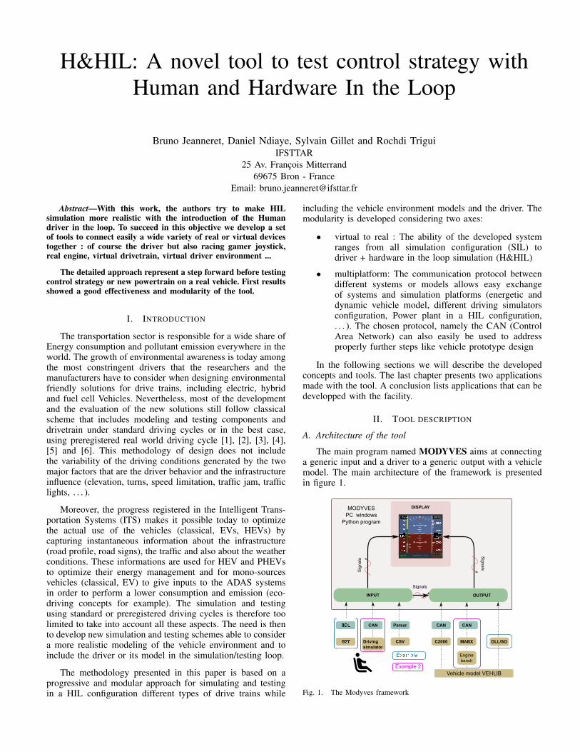
The main program named MODYVES aims at connectinga generic input and a driver to a generic output with a vehiclemodel. The main architecture of the framework is presentedin figure 1.
DISPLAY
INPUT OUTPUT
G27 Driving
simulator
CSV C2000 MABX
CAN CANSDL CAN Parser
Sig
na
ls
Sig
na
ls
Signals
MODYVES
PC windows
Python program
Engine
bench
Example 2
Vehicle model VEHLIB
DLL/SO
Fig. 1. The Modyves framework
Inputs can be choosen among:
• a Gamepad like Logitech G27 Joystick or equivalent.Modyves uses Simple DirectMedia Layer 1 to providelow level access to the device
• IFSTTAR’s driving simulator
• a csv file to replay some experiments
Several kind of outputs consisting of the vehicle model aresupported:
• Texas Instrument C2000 control card
• dSPACE Hardware with Power Hardware In The Looplike engine test bench
• Dynamic Link Library file
B. Communication layer
The CAN protocol is widely used in automotive industry.For this reason, we selected this kind of network for thecommunication of the different pieces of hardware. Easy toimplement, another advantage is that the communication canbe secured by testing the Rx time (Received frame) in a realtime clock.
Two different USB to CAN converter have been integratedin the tool, PEAK 2 module and Systec 3 module.
Both provide device driver (Dynamic Link Library files)and header files to connect to the module and parametrise it,decode received frame and send transmitted ones.
C. Hardware
Two main hardwares have been integrated in our tool,a prototyping hardware commercialised by dSPACE, namelyMicro-autobox (MABX-II), and a low cost 32 bit microcon-troler from Texas Instrument, the C2000 Peripheral Experi-menter kit equipped with a F28335 control card. Both aresupported by The Mathworks with matlab and simulink coderfor dSPACE hardware, and matlab and embedded coder forC2000.
The table I makes a short comparison between hardwares.
F28335 MABX-II (1401/1501)Processor 150 MHz 900 MHz
RAM 68 kB (+256 kB SRAM) 16 MBFlash memory 512 kB 16 MBAnalog input 16 (12 bits) 16 (12 bits)Can network 2 4
Analog output 0 8 (12 bits)PWM 6 4 in, 4 out
Bit I/O 16 DI, 10 DO, 16 shared DIO 34 shared DIO
TABLE I. HARDWARE CHARACTERISTICS
Of course these two devices have not the same perfor-mances and are not suitable for the same kind of application.
One can notice the power of dSPACE board (procesorspeed and size of RAM and Flash), but the major advantage
1https://www.libsdl.org/2http://www.peak-system.com/3http://www.systec-electronic.com/
of the tool is its combinations with a RTI interface andcontrolDesk software that enable to rapidly develop, debugand validate a real time project.
On the other hand, TI C2000 control card is well suitedfor a variety of automotive applications. If offers a goodprocessor speed with a moderate but sufficient Flash memoryto developp and embed a real time application at a moderateprice. Debugging is far more complex than with dSPACEproduct.
D. Software
Modyves is written in python and is cadenced by awindows timer, so depending upon computer characteristicsand computer load, it can deviate from its theorical executionperiod. Nevertheless, when connected to real plant, the onlycritical part running in Modyves is the driver behavior and thecommunication layer.
The IFSTTAR driving simulator is a static driving sim-ulator based on a real Peugeot 308 and a software partnamed SIM2. The cockpit and all commands are unchangedto offer the most realistic driving environments to the driver.An embedded electronic card in the vehicle reads all sensorsvalues placed on the pedals, the gearbox and the steeringwheel. It also controls the force feedback on the steering wheel.The electronic card controls the vehicle dashboard by sendingCAN informations through the OBD connector. SIM2 is theIFSTTAR simulator software, and contains various types ofmodels: vehicle, road, sound, traffic and visual models. Theroad scene is displayed on 5 screens offering up to 180°horizontal Field Of View. The IFSTTAR driving simulatoris used in the field of human factor research, ergonomicsstudies, energy-efficient driving, advanced training and studiesof “Human and Hardware in Loop”( H&HIL).
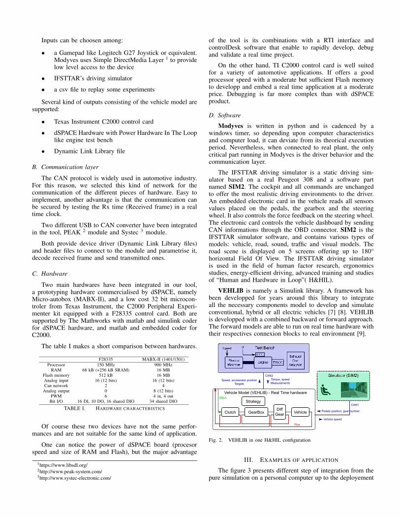
VEHLIB is namely a Simulink library. A framework hasbeen developped for years around this library to integrateall the necessary components model to develop and simulateconventional, hybrid or all electric vehicles [7] [8]. VEHLIBis developped with a combined backward or forward approach.The forward models are able to run on real time hardware withtheir respectives connexion blocks to real environment [9].
Electric
MachineEngine
ECU
TWCC
Exhaust
Gaz
Analyser
Diff
GearClutch GearBox Vehicle
Vehicle Model (VEHLIB) - Real Time hardware
Strategy
Flux
Effort
Vehicle speed
CAN1
Pedals position, gear number
CAN2
Torque, speed
MeasurementsSpeed, accelerator position
Targets
Fig. 2. VEHLIB in one H&HIL configuration
III. EXAMPLES OF APPLICATION
The figure 3 presents different step of integration from thepure simulation on a personal computer up to the deployement
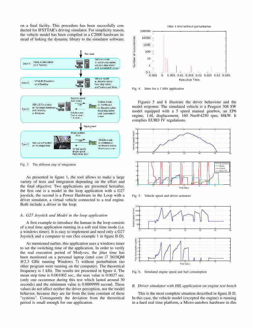
on a final facilty. This procedure has been succesfully con-ducted for IFSTTAR’s driving simulator. For simplicity reason,the vehicle model has been compiled in a C2000 hardware in-stead of linking the dynamic library to the simulator software.
Step 4: VEHLIB Simulation
on the target hdw
Vehicle model
w. continuous
or discrete states
fixed step solver
Fig. 3. The different step of integration
As presented in figure 1, the tool allows to make a largevariety of tests and integration depending on the effort andthe final objective. Two applications are presented hereafter,the first one is a model in the loop application with a G27joystick, the second is a Power Hardware in the Loop with adriver simulator, a virtual vehicle connected to a real engine.Both include a driver in the loop.
A. G27 Joystick and Model in the loop application
A first example to introduce the human in the loop consistsof a real time application running in a soft real time mode (i.e.a windows timer). It is easy to implement and need only a G27Joystick and a computer to run (See example 1 in figure II-D).
As mentioned earlier, this application uses a windows timerto set the switching time of the application. In order to verifythe real execution period of Modyves, the jitter time hasbeen monitored on a personal laptop (intel core i7 [email protected] GHz running Windows 7) without perturbation (noother program were running on the computer). The theoreticalfrequency is 1 kHz. The results are presented in figure 4. Themean step time is 0.001002 sec., the max value is 0.0027 sec.(only one occurence during this test which lasted around 30seconds) and the minimum value is 0.0009999 second. Thesevalues do not affect neither the driver perception, nor the modelbehavior, because they are far from the time constant of these"systems". Consequently the deviation from the theoreticalperiod is small enough for our application.
Fig. 4. Jitter for a 1 kHz application
Figures 5 and 6 illustrate the driver behaviour and themodel response. The simulated vehicle is a Peugeot 308 SWmodel equipped with a 5 speed manual gearbox, an EP6engine, 1.6L displacement, 160 Nm@4250 rpm, 88kW. Itcomplies EURO IV regulations.
0 10 20 30 40 50 600
10
20
30
40
50
Vehic
le s
peed (
km
/h)
0 10 20 30 40 50 600
20
40
60
80
100
Time (sec.)
Accelerator
Brake
Clutch
Gear*10
Fig. 5. Vehicle speed and driver actuators
0 10 20 30 40 50 600
500
1000
1500
2000
2500
Engin
e s
peed (
tr/m
n)
0 10 20 30 40 50 600
0.2
0.4
0.6
0.8
1
1.2
1.4
Fuel C
onsum
ption (
g/s
ec)
Time (sec.)
Fig. 6. Simulated engine speed and fuel consumption
B. Driver simulator with HIL application on engine test bench
This is the most complete situation described in figure II-D.In this case, the vehicle model (excepted the engine) is runningin a hard real time platform, a Micro-autobox hardware in this
particular case. The latter communicates with the engine testbench and exchange some informations with it, namely:
• send accelerator pedal position to the engine androtation speed to the electric generator
• receive actual torque
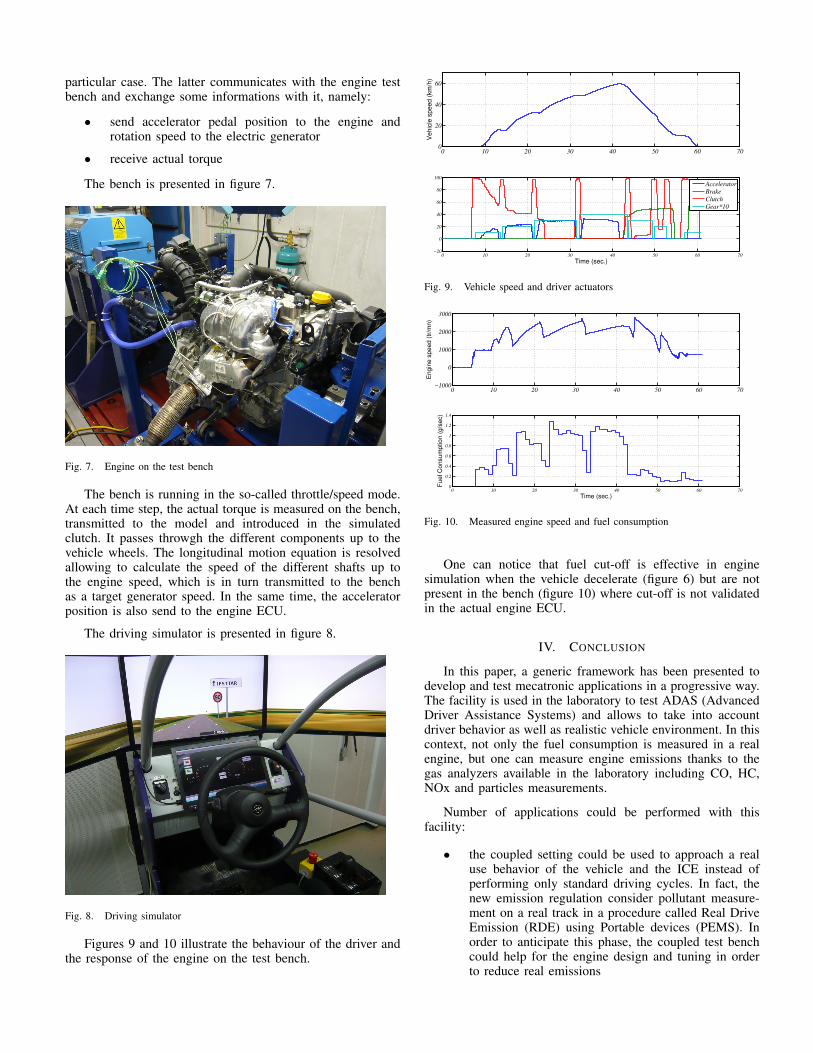
The bench is presented in figure 7.
Fig. 7. Engine on the test bench
The bench is running in the so-called throttle/speed mode.At each time step, the actual torque is measured on the bench,transmitted to the model and introduced in the simulatedclutch. It passes throwgh the different components up to thevehicle wheels. The longitudinal motion equation is resolvedallowing to calculate the speed of the different shafts up tothe engine speed, which is in turn transmitted to the benchas a target generator speed. In the same time, the acceleratorposition is also send to the engine ECU.
The driving simulator is presented in figure 8.
Fig. 8. Driving simulator
Figures 9 and 10 illustrate the behaviour of the driver andthe response of the engine on the test bench.
0 10 20 30 40 50 60 700
20
40
60
Vehic
le s
peed (
km
/h)
0 10 20 30 40 50 60 70−20
0
20
40
60
80
100
Time (sec.)
Accelerator
Brake
Clutch
Gear*10
Fig. 9. Vehicle speed and driver actuators
0 10 20 30 40 50 60 70−1000
0
1000
2000
3000
Engin
e s
peed (
tr/m
n)
0 10 20 30 40 50 60 700
0.2
0.4
0.6
0.8
1
1.2
1.4
Fuel C
onsum
ption (
g/s
ec)
Time (sec.)
Fig. 10. Measured engine speed and fuel consumption
One can notice that fuel cut-off is effective in enginesimulation when the vehicle decelerate (figure 6) but are notpresent in the bench (figure 10) where cut-off is not validatedin the actual engine ECU.
IV. CONCLUSION
In this paper, a generic framework has been presented todevelop and test mecatronic applications in a progressive way.The facility is used in the laboratory to test ADAS (AdvancedDriver Assistance Systems) and allows to take into accountdriver behavior as well as realistic vehicle environment. In thiscontext, not only the fuel consumption is measured in a realengine, but one can measure engine emissions thanks to thegas analyzers available in the laboratory including CO, HC,NOx and particles measurements.
Number of applications could be performed with thisfacility:
• the coupled setting could be used to approach a realuse behavior of the vehicle and the ICE instead ofperforming only standard driving cycles. In fact, thenew emission regulation consider pollutant measure-ment on a real track in a procedure called Real DriveEmission (RDE) using Portable devices (PEMS). Inorder to anticipate this phase, the coupled test benchcould help for the engine design and tuning in orderto reduce real emissions
• the facility could embed ADAS system. They canbe easily implemented and tested on urban, road orhighway context with a human driver in the loop. Forexample, the assistance systems for eco-driving couldbe assessed in terms of near-real fuel consumption andpollutant emission
• the simulator can be a platform to evaluate differentdegrees of driving delegation towards autonomousvehicle. For example, it is easy to simulate manualor automatic gearbox, to test different kind of speedregulator, speed limitation...
• hybrid vehicles can be emulated in the real time modelor they can be introduced in the bench to simulatehybrid vehicle. A clutch can also be physically presentto test all electric mode for a parallel hybrid vehicle.With this kind of application, several energy manage-ment laws can be quickly implemented and tested ina almost real environment
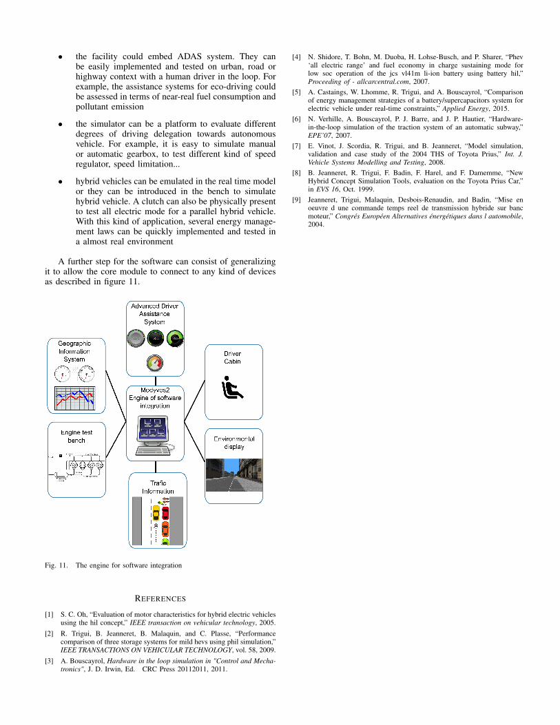
A further step for the software can consist of generalizingit to allow the core module to connect to any kind of devicesas described in figure 11.
Fig. 11. The engine for software integration
REFERENCES
[1] S. C. Oh, “Evaluation of motor characteristics for hybrid electric vehiclesusing the hil concept,” IEEE transaction on vehicular technology, 2005.
[2] R. Trigui, B. Jeanneret, B. Malaquin, and C. Plasse, “Performancecomparison of three storage systems for mild hevs using phil simulation,”IEEE TRANSACTIONS ON VEHICULAR TECHNOLOGY, vol. 58, 2009.
[3] A. Bouscayrol, Hardware in the loop simulation in "Control and Mecha-tronics", J. D. Irwin, Ed. CRC Press 20112011, 2011.
[4] N. Shidore, T. Bohn, M. Duoba, H. Lohse-Busch, and P. Sharer, “Phev‘all electric range’ and fuel economy in charge sustaining mode forlow soc operation of the jcs vl41m li-ion battery using battery hil,”Proceeding of - allcarcentral.com, 2007.
[5] A. Castaings, W. Lhomme, R. Trigui, and A. Bouscayrol, “Comparisonof energy management strategies of a battery/supercapacitors system forelectric vehicle under real-time constraints,” Applied Energy, 2015.
[6] N. Verhille, A. Bouscayrol, P. J. Barre, and J. P. Hautier, “Hardware-in-the-loop simulation of the traction system of an automatic subway,”EPE’07, 2007.
[7] E. Vinot, J. Scordia, R. Trigui, and B. Jeanneret, “Model simulation,validation and case study of the 2004 THS of Toyota Prius,” Int. J.Vehicle Systems Modelling and Testing, 2008.
[8] B. Jeanneret, R. Trigui, F. Badin, F. Harel, and F. Damemme, “NewHybrid Concept Simulation Tools, evaluation on the Toyota Prius Car,”in EVS 16, Oct. 1999.
[9] Jeanneret, Trigui, Malaquin, Desbois-Renaudin, and Badin, “Mise enoeuvre d une commande temps reel de transmission hybride sur bancmoteur,” Congrés Européen Alternatives énergétiques dans l automobile,2004.