Embed Size (px)
Citation preview
SOU500 HANDBOOK 050213
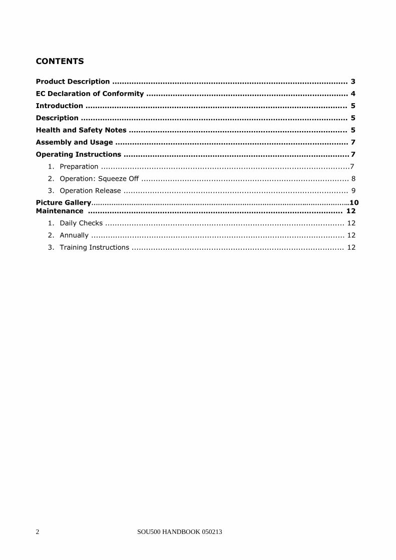
HANDBOOK
Squeeze Off Unit SOU 500
Please refer any queries to:
Hy – Ram Engineering Co Ltd Pelham Street Mansfield
Nottinghamshire NG18 2EY Telephone No: (01623) 422982
Please note all queries should state the type and serial number of the unit.
2 SOU500 HANDBOOK 050213
CONTENTS
Product Description .................................................................................................. 3
EC Declaration of Conformity .................................................................................... 4
Introduction ............................................................................................................. 5
Description ............................................................................................................... 5
Health and Safety Notes ........................................................................................... 5
Assembly and Usage ................................................................................................. 7
Operating Instructions .............................................................................................. 7
1. Preparation .......................................................................................................7
2. Operation: Squeeze Off ...................................................................................... 8
3. Operation Release ............................................................................................. 9
Picture Gallery…………………………………………………………………………………….………………..10
Maintenance .......................................................................................................... 12
1. Daily Checks ................................................................................................... 12
2. Annually ......................................................................................................... 12
3. Training Instructions ........................................................................................ 12
SOU500 HANDBOOK 050213 3
PRODUCT DESCRIPTION
The Hy-Ram SOU500 Squeeze Off Unit has the facility to enable four simultaneous
Squeeze points to be executed. The unique design with dual hydraulic cylinders provides the hydraulic power to squeeze the pipe to the optimum compression,
(squeeze gap set by pipe stop), then the Squeeze and Bottom Beams are very simply
mechanically locked together.
The Detachable Beam incorporating the hydraulic cylinders can be easily disconnected
from the assembly and carried to the desired position for the next squeeze point. The
Detachable beam can now be connected to a second Beam Set and a second squeeze operation can be carried out. With four Beam Sets being supplied in the standard kit,
by repeating the procedure above, four simultaneous squeeze points can be achieved.
Type and Series of machine:
Year of Manufacture:
Serial Number:
Weight:
This unit is intended for Squeezing off PE80 pipes within the Gas industry.
[Please note this is not a ‘Controlled Release’ Squeeze Off Unit] No other uses are considered appropriate for this unit.
To use this unit for other purposes without first consulting Hy – Ram
Engineering Co Ltd could lead to the unit being used for dangerous applications and may cause injury.
The information contained in this manual is to assist with the safe installation, operation, maintenance and repair of the equipment.
This information should be made available to all persons who are required to work with or on the equipment.
If in any doubt as to any aspects of this equipment, the application of this
equipment or the instructions in this handbook, you should contact Hy-Ram Engineering Co Ltd. for clarification or advice.
This machine has been made to a defined specification – additional information specific to this machine is:
_____________________________________________________________________
__________________________________________________________________________________________________________________________________________
_____________________________________________________________________
_____________________________________________________________________
__________________________________________________________________________________________________________________________________________
_____________________________________________________________________
______
4 SOU500 HANDBOOK 050213
EC DECLARATION OF CONFORMITY
We hereby declare that the following machinery complies with the essential health and safety requirements of the Machinery Directive 2006/42/EC enacted in the United
Kingdom by The Supply of Machinery(Safety) Regulations 2008.
Machine description: Squeeze Off Unit
Make: Hy-Ram Type: SOU500
Serial number: ______________ Year of construction: _____________
Manufactured by: Hy-Ram Engineering Co Ltd. Pelham Street
Mansfield
Nottinghamshire NG18 2EY
This machinery has been designed and manufactured in accordance with the following
transposed harmonised European standards.
BS EN ISO 12100:2010 Safety of Machinery - General principles for design. Risk
assessment and risk reduction. BS EN ISO 13857:2008 Safety of Machinery – Safety distances to prevent hazard
zones being reached by upper and lower limbs.
BS EN 349:1993+A1:2008 Safety of Machinery – Minimum gaps to avoid crushing of parts of the human body.
BS EN ISO 4413:2010 Hydraulic Fluid Power – General rules and safety requirements
for systems and their components.
BS EN ISO 4414:2010 Pneumatic Fluid Power – General rules and safety requirements for systems and their components.
A technical construction file for this machinery is retained at the following address:
Pelham Street Mansfield
Nottinghamshire
NG18 2EY
Signed:__________________________
Date:_____________________________
Name:___________________________
Position:__________________________
Being the responsible person appointed by the manufacturer, and employed by
Hy-Ram Engineering Co Ltd.
SOU500 HANDBOOK 050213 5
INTRODUCTION
This manual explains about the machinery and how to use and maintain it. It is intended for
Users and should be made available to all persons who are likely to use the machinery. There are a number of Warning, Caution and Note Statements and these notify you of important points: WARNING: Informs of hazardous conditions which may cause serious bodily harm.
CAUTION: Informs of conditions which may cause damage to equipment. NOTE: Explains additional or helpful information.
A. DESCRIPTION The Hy-Ram SOU500 Squeeze Off Unit has the facility to enable four simultaneous Squeeze points to be executed. The unique design with dual hydraulic cylinders provides the hydraulic power to squeeze the pipe to the optimum compression, (squeeze gap set by pipe stop), then the Top and Bottom Beams are very simply mechanically locked together.
B. HEALTH AND SAFETY NOTES
General
This Squeeze off unit present dangers from trapping parts of the body between the
slow moving parts and from the hydraulic oil should a hose burst. The danger zone is
the immediate area around the Squeeze beam and bottom beam where the PE pipe is
being squeezed off.
WARNING
BEFORE any work is carried out on this unit, the equipment should be isolated
from the electrical supply.
Other hazards are those involving the lifting of the unit and its component parts. There
are handles on the unit that can be used as lifting points for the component parts.
These are designed to lift the component only and not the unit complete. It is not envisaged that the assembled unit can be manually handled without the aid of specific
mechanical assistance.
Component Weights
Hydraulic Cylinders and Top Beam (Qty 1) 230 Kg Squeeze Beam (4 Qty) 73 Kg each
Bottom Beam (4 Qty) 70 Kg each
Guide Rods (8 Qty) 30 Kg each Pins (8 Qty short and 2 Qty long) 13 Kg total
Electrical Power Unit, 110V, 1.1KW 100 Kg
Hydraulic Hoses 15 Kg
Tool Box (inc. Pins and Bolts) 46 Kg Carrying Frame (inc. Power pack) 785 Kg
Carrying Frame (inc. Beams) 942 Kg
bolts 22.5 Kg
6 SOU500 HANDBOOK 050213
Pipe Stop set 400/21 5.5 Kg
Pipe Stop set 400/17.6 6.5 Kg
Pipe Stop set 400/11 10.0 Kg
Pipe Stop set 450/21 6.0 Kg
Pipe Stop set 450/17.6 7.0 Kg
Pipe Stop set 450/11 11.0 Kg
Pipe Stop set 469/21 6.0 Kg
Pipe Stop set 500/26 5.0 Kg
Pipe Stop set 500/21 6.5 Kg
Pipe Stop set 500/17.6 8.0 Kg
Pipe Stop set 500/11 12.0 Kg
This machine is designed to be adjusted and maintained without placing persons at risk.
WARNING
Users are responsible for ensuring compliance with the Noise at Work Regulations.
SOU500 HANDBOOK 050213 7
C. ASSEMBLY AND USAGE
SOU 500 SQUEEZE OFF UNIT
Equipment:
Hydraulic Cylinders and Top Beam (Qty 1)
Squeeze Beam (4 Qty) Bottom Beam (4 Qty)
Guide Rods (8 Qty)
Pins (8 Qty short and 2 Qty long) Electrical Power Unit
Hydraulic Hoses
Tool Box (inc. Pins and Bolts)
Carrying Frame (inc. Power pack) Carrying Frame (inc. Beams)
Various Pipe Stops
NOTE
Dependant on specified requirements, the equipment kit may contain up to 6 x top
beams, 6 x bottom beams and 6 x pairs of stops.
WARNING
These instructions should be followed in sequential order.
OPERATING INSTRUCTIONS
1.0 PREPARATION
1.1 The Hydraulic Rams should always be transported with the Rams closed. This is
to protect the Piston Rods from being damaged.
1.2 Centrally position (1 of 4) Bottom Beams underneath the pipe to be squeezed off
at the desired squeeze off point.
1.3 Load (2 of 8) Guide Bars into the Bottom Beam and lock into position with (2 of 8) Short Pins. Retain Pins with ‘R’ Clips
1.4 Identify the pipe diameter and SDR and position (2 of 8) pipe stops on the Guide Bars.
1.5 Load Squeeze Beam onto the Guide Bars and rest underside of Beam onto top of Pipe.
8 SOU500 HANDBOOK 050213
1.6 Load Top Beam (incorporating Hydraulic Rams) onto the Guide bars and retain
with the 2 Long Pins. Retain Pins with ‘R’ Clips
1.7 Connect Hydraulic Hoses between Electrical Power Unit and Top Beam. WARNING: Ensure Couplings are clean before connecting. It is essential to make
these connections fully tight! There should be no gap between the Nut on the
Female half Coupling and Male half Coupling. THE HYDRAULIC HOSES MUST BE CONNECTED IN PAIRS!
1.8 Connect Power Unit to a suitable 110V / 50Hz supply. The Unit has a 16 Amp plug. The Electric Motor is 110V / 1.1KW. Switch power on.
1.9 Select ‘Neutral’ position on the Valve handle. Start Power Pack.
1.10 Select ‘Squeeze Off’ and extend Hydraulic Rams by approximately 50mm. Then
select ‘Squeeze Off Release’ and Hydraulic rams will retract. REPEAT THIS
SEQUENCE APPROXIMATELY FIVE TIMES IN ORDER TO BLEED THE SYSTEM AND ALIGN HYDRAULICS. WHEN THIS OPERATION HAS BEEN CARRYED OUT
SUFFICIENTLY, IT SHOULD BE NOTED THAT THE RAMS ARE EXTENDING AT THE
SAME RATE (SYCHRONISED).
2.0 OPERATION : SQUEEZE OFF
2.1 WARNING! Ensure the pipe is loaded centrally across the width of the beams.
Select ‘Squeeze Off’ and observe the Hydraulic Rams extending at the same rate
2.2 Observe pipe being squeezed. Squeeze Off will stop when Squeeze Beam
contacts each Pipe Stop simultaneously.
2.3 After ensuring metal-metal contact between Squeeze Beam and Pipe Stops, the
Squeeze Beam is to be mechanically bolted to the Bottom Beam. Leave the
Power Unit running and the leave the Valve position in ‘Squeeze Off’. The ‘Lock Down’ Bolts and Ratchet/Socket are provided in the Tool Box. WARNING:
Selection of the correct length bolt is CRITICAL! The length required varies
dependent on which Pipe Stops are being used. Select a bolt that is sufficiently long to give a minimum thread engagement of 45mm (i.e 1.5 x M30 dia. =
45mm). Tighten to a Torque of 200Nm.???????
2.4 Once Bolts are tight, select ‘Squeeze Off Release’ and observe the Hydraulic Rams retracting.
2.5 Once Hydraulic rams are fully retracted, select ‘Neutral’ position and switch off Power Unit.
2.6 Top Beam assembly should now be detached from the Guide bars by removing the ‘R’ Clips and then the Pins.
2.7 Other Squeeze off operations now be carried out using the same procedure i.e
1.1 – 1.10 and 2.1 – 2.6. NOTE: Procedure 1.11 is not necessary for subsequent Squeezes; it is only necessary upon start-up when the oil is cold.
SOU500 HANDBOOK 050213 9
3.0 OPERATION RELEASE
3.1 To release a squeeze off point, firstly ensure that the Hydraulic Rams are fully
retracted. The top Beam should then be re-loaded onto the Guide Bars as described in 1.3 above.
3.2 Repeat steps 1.6 to 1.10 above in order that the Hydraulic Cylinders extend and re-contact the top of the Squeeze Beam.
3.3 After ensuring that the load is being taken up Hydraulically again on both sides, leave the Power Unit running and the ‘Squeeze off’ position selected. Un-do the
Bolts and remove.
WARNING Never attempt to release a squeeze off until the load is taken up on the
hydraulic cylinders.
3.4 Select the ‘Squeeze Off Release’ position . The Top Beam
will travel upwards, the squeeze off will release and the pipe will begin to re-
round.
3.5 Allow the Rams to fully retract and then select ‘Neutral’ and switch off the Power
Unit.
3.6 The squeeze off release is now completed and other squeeze points
can be released in the same manner repeating steps 3.1 – 3.6.
Note! Before attempting to disconnect couplings from the cylinder, ensure that the
power unit is run for a short time, in the ‘Neutral’ position to discharge the pressure in
the hoses. (A Coupling cannot be disconnected whilst pressure is locked in the hoses).
10 SOU500 HANDBOOK 050213
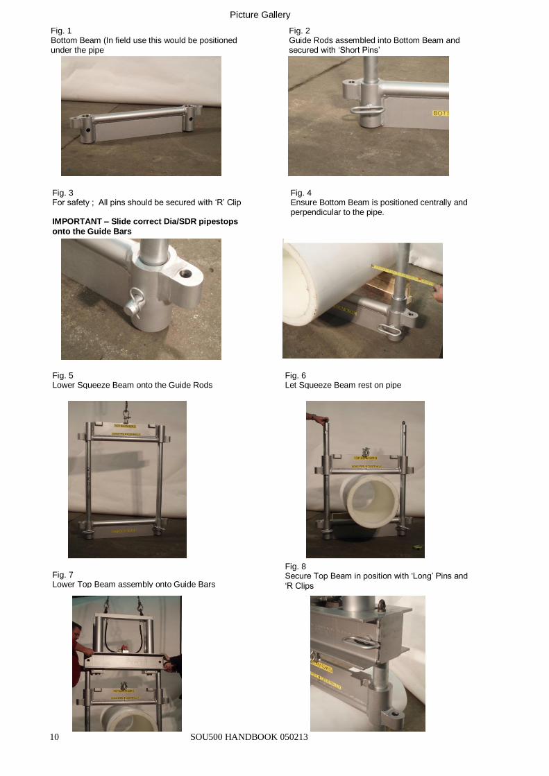
Fig. 3 For safety ; All pins should be secured with ‘R’ Clip IMPORTANT – Slide correct Dia/SDR pipestops
onto the Guide Bars
Fig. 2 Guide Rods assembled into Bottom Beam and secured with ‘Short Pins’
Fig. 1 Bottom Beam (In field use this would be positioned under the pipe
Fig. 5 Lower Squeeze Beam onto the Guide Rods
Fig. 6 Let Squeeze Beam rest on pipe
Fig. 7 Lower Top Beam assembly onto Guide Bars
Fig. 8 Secure Top Beam in position with ‘Long’ Pins and
‘R Clips
Fig. 4 Ensure Bottom Beam is positioned centrally and perpendicular to the pipe.
Picture Gallery
SOU500 HANDBOOK 050213 11
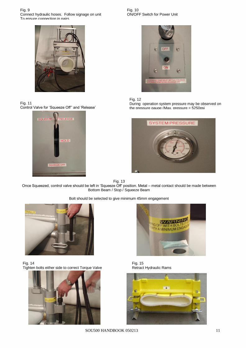
Fig. 9 Connect hydraulic hoses. Follow signage on unit To ensure connection in pairs
Fig. 10 ON/OFF Switch for Power Unit
Fig. 11 Control Valve for ‘Squeeze Off’’ and ‘Release’
Fig. 12 During operation system pressure may be observed on the pressure gauge (Max. pressure = 5250psi
Fig. 13 Once Squeezed, control valve should be left in ‘Squeeze Off’ position. Metal – metal contact should be made between
Bottom Beam / Stop / Squeeze Beam
Bolt should be selected to give minimum 45mm engagement
Fig. 14
Tighten bolts either side to correct Torque Valve
Fig. 15
Retract Hydraulic Rams
12 SOU500 HANDBOOK 050213
MAINTENANCE
There are no internal wearing parts for the user to change.
Faults or problems should be reported to Hy-Ram Engineering Co Ltd stating the Serial Number and the size of the machine. Any alteration will leave the guarantee null and void
DAILY CHECKS
The Oil level
Condition of the hoses
General Condition
ANNUALLY
The complete unit should be returned to the Hy-Ram on an annual basis for
maintenance checks and service work.
TRAINING INSTRUCTIONS
It is not envisaged that this equipment can be used by anyone, only trained operators, familiar with the gas industry should use this equipment.
Users also need to be made aware of the significant noise generated by the power unit and of the need to take appropriate precautions